

Page 1

Errata
Title & Document Type: 300A Harmonic Wave Analyzer
Manual Part Number: N/A
Revision Date: 11/30/1955
HP References in this Manual
This manual may contain references to HP or Hewlett-Packard. Please note that
Hewlett-Packard's former test and measurement, semiconductor products and chemical
analysis businesses are now part of Agilent Technologies. We have made no changes to
this manual copy. The HP XXXX referred to in this document is now the Agilent XXXX.
For example, model number HP8648A is now model number Agilent 8648A.
About this Manual
We’ve added this manual to the Agilent website in an effort to help you support your
product. This manual provides the best information we could find. It may be incomplete
or contain dated information, and the scan quality may not be ideal. If we find a better
copy in the future, we will add it to the Agilent website.
Support for Your Product
Agilent no longer sells or supports this product. You will find any other available product
information on the Agilent Test & Measurement website:
www.tm.agilent.com
Search for the model number of this product, and the resulting product page will guide
you to any available information. Our service centers may be able to perform calibration
if no repair parts are needed, but no other support from Agilent is available
Page 2
t
OPERATING
MANUAL
PLUS
SERVICE
MANUAL
MODEL
300A
HARMONIC
WAVE
ANALYZER
This
isacombined
Operation,
Instruction,
and
Service
Manual
for
all
~
Mode1300A
Harmonic
Wave
Analyzers.
This
manual
contains
complete
operation
and
servicing
instructions
for
the
300A
and
may
be
used
in
place
of
thl~
Instruction
and
Operating
Manual
originally
supplied
with
each
ins
trument.
Copyright
1956
by
Hewlett-Packard
Company
The
information
contained
in
this
booklet
is
intended
for
the
operation
and
main-
tenance
of
Hewlett-Packard
equipment
and
is
not
to
be
used
otherwise
or
reproduced
without
the
written
consent
of
the
Hewlett-
Packard
Company.
HEWLETT-PACKARD
COMPANY
PAGE
MILL
ROAD,
PALO
ALTO,
CALIFORNIA,
U.S.A.
Page 3
II
MODEL
300A
HARMONIC
WAVE
ANALYZER
INSTRUCTION
&
OPERATING
MANUAL
TABLE
OF
CONTENTS
SECTION
I
GENERAL
Page
1-1
1-2
GENERAL
DESCRIPTION
SPECIFICATIONS
• • •
· . . .
· .
· .
· .
III
III
SECTION
II
OPERATING
INSTRUCTIONS
2
-1
23D
VOLT
OPERATION.
·
· ·
·
·
·
·
· · · ·
•
III
2
-2
CONTROLS
&
TERMINALS
· · ·
·
·
· · · · ·
•
IV
2
-3
OPERATION.
. . . .
· ·
·
· · · · · · ·
• •
· · · · ·
IV
2-4
CALIBRATION
ADJUSTMENT
PROCEDURE.
·
·
·
• •
IV
2
-5
MEASUREMENT
PROCEDURE.
· · · · ·
•
·
·
·
IV
2
-6
MEASUREMENT
PRECAUTIONS.
·
· · · · · · · ·
•
V
2-7
SELECTIVITY.
. . .
· · · · · · · · · ·
•
V
SECTION
III
CIRCUIT
DESCRIPTION
3-1
GENERAL
••••
· . . . . . . . . . .. . . . .
SECTION
IV
MAINTENANCE
VI
4-1
CABINET
REMOVAL.
· · · · ·
·
· · ·•· ·
•
·
·
VII
4-2
TUBE
REPLACEMENT.
·
· · · · · · ·
·
·
•
·
•
·
•
·
VII
4-3
LOCAL
OSCILLATOR
AMPLITUDE
ADJUSTMENT.
•
·
VII
4-4
VOLTAGE
REGULATOR
ADJUSTMENT.
· ·
• • •
·
•
·
•
VII
4-5
HUM
BALANCE
ADJUSTMENT.
· ·
•
·
• • • • • • • •
·
VII
4-6
BALANCED
MODULATOR
ADJUSTMENT.
•
· ·
• •
·
VII
4-7
SELECTIVE
AMPLIFIER
ADJUSTMENT
· ·
•
· ·
•
·
VII
SECTION
V
TABLE
OF
REPLACEABLE
PARTS
5-1
GENERAL.
. . . . . . . . . . . . . . . . .. . . . .
VII
THE
ATTACHED
300A-2
SERVICE
MANUAL
HASASEPA-
RATE
INDEX
APPEARING
ON
PAGE
1.
..
Page 4
III
INSTRUCTION
&
OPERATING
MANUAL
SECTION
I
GENERAL
1-1
GENERAL
DESCRIPTION
The
Model
300A
Harmonic
Wave
Analyzer
isaselective
voltmeter
designed
to
measure
the
individual
components
of
complex
waves.
The
selectivity
can
be
varied
by
means
of
selective
amplifiers
to
measure
either
closely
or
widely
spaced
harmonics.
The
instrument
coversthe
audio
spectrum
from
30
to
16,000
cps.
It
has
a
wide
voltage
range
so
that
full
scale
readings
may
be
ob-
tained
from
1
millivolt
to
500
volts
0
The
Model
300A
is
well
adapted
to
the
measurement
of
the
harmonic
distortion
in
audio
frequency
equipment
of
all
kinds,
broadcast
receivers,
transmitters;
to
determine
the
harmonic
components
in
ac
machinery
and
power
systems;
to
the
study
of
induced
voltages
on
telephone
lines;
and
to
measurement
of
hum
components
in
rectifier
circuits.
Other
uses
include
the
study
of
noise
by
integrating
portions
of
the
spectrum
with
the
selectivity
control
adjusted
for
a
wide
pass
band
and
the
checking
of
wave
filter
characteristics
with
maximum
selectivity.
The
Model
300A
is
also
useful
asadevice
to
measure
the
amount
of
cross
or
intermodulation
products
generated
by
the
simultaneous
transmis
sion
of
two
frequencies
by
an
audio
system
or
to
measure
demodulation
ofamodulated
wave
applied
through
an
audio
system.
1
-2
SPECIFICATIONS
Complete
specifications
for
the
cEiJ
Model
300A
Harmonic
Wave
Analyzer
will
be
found
on
page
3
of
the
cEiJ
No.
300A-2
Service
Manual.
SECTION
II
OPERATING
INSTRUCTIONS
2-1
230
VOLT
OPERATION
This
instrument
is
shipped
from
the
factory
with
the
power
transformer
pri-
maries
connected
in
parallel
for
operation
from
115
volts.
If
operation
from
a
power
line
of
230
volts
is
desired,
the
power
transformer
primaries
must
be
connected
in
series
as
shown
by
the
"Transformer
Detail"
on
the
schematic
diagram
in
Fig.
3
on
page
39
of
the
No.
300A-2
Service
Manual.
Some
older
instruments
have
a
power
transformer
with
a
single
primary
wind-
ing
for
operation
from
115
volts
only.
The
1.
25
ampere
slo-blo
fuse
required
for
115
volt
operation
must
be
replaced
by
a
0.6
ampere
slo-blo
fuse
after
changing
primary
connections
from
parallel
to
series
for
operation
from
230
vo.lts.
Page 5
IV
2-2
CONTROLS
AND
TERMINALS
All
controls
and
terminals
are
fully
des
cribed
on
pages
4
and
5
of
the
r5j:;
No.
300A-2
Service
ManuaL
CAUTION
THIS
INSTRUMENT
IS
ACCURATE
AT
AMBIENT
TEMPERATURES
OF
APPROXIMATELY
55
TO
95
DEGREES
FAHRENHEIT.
OTHER
AMBI-
ENT
TEMPERATURES
MAY
NECESSITATE
REALIGNMENT
OF
THE
SELECTIVE
AMPLIFIER
SYSTEM.
2-3
OPERATION
The
operation
of
the
Model
300A
is
divided
into
two
parts.
the
calibration
adjustment
procedure
and
the
measurement
procedure.
2-4
CALIBRATION
ADJUSTMENT
PROCEDURE
This
procedure
will
be
found
under
the
heading
of
CALIBRATION
PROCE-
DURE
starting
on
page
11
of
the
r5j:;
No.
300A-2
Service
Manual.
See
the
important
operating
precautions
given
in
step
26
of
CALIBRA
TION
PROCEDURE
in
the
No.
300A-2
manual.
2-5
MEASUREMENT
PROCEDURE
The
instrument
must
be
calibrated
before
attempting
a
measurement.
In
the
following
procedure,
the
voltage
being
analyzed
has
a
fundamental
frequency
of
80
cps
and
an
amplitude
of
20
volts.
The
frequency
and
amplitude
of
this
hypothetical
voltage
have
been
as
sumed
to
simplify
the
instructions.
Any
voltage
between
1
millivolt
and
500
volts
at
any
frequency
between
30
to
16,
000
cps
could
be
similarly
measured.
A
harmonic
frequency
must
not
be
higher
'than
16.
000
cps
if
the
particular
harmonic
voltage
is
to
be
measured.
a.
Calibrate
the
300A
as
previously
described.
b.
Set
the
METER
MULTIPLIER
control
to
50
(XIOO)
and
the
SET
TO
100
FOR
VOLT
AGE
MEASUREMENT
control
to
100.
c.
Set
the
HALF
BAND
WIDTH
control
to
30.
See
step
26B
on
page
12
of
No.
300A-2
Service
Manual
regarding
the
degree
of
selectivity
neces-
sary
for
measuring
voltages
of
various
frequencies.
d.
Set
the
frequency
dial
to
80
cps
and
peak
the
meter
indication
by
adjust-
ing
the
FINE
TUNING
control.
The
METER
SENSITIVITY
control
should
be
adjusted
to
giveareadable
indication
on
the
millivoltmeter.
The
in-
strument
is
now
tuned
to
measure
the
amplitude
of
the
fundamental
fre-
quency
(80
cps)
with
the
harmonics
excluded.
e.
The
actual
value
of
the
funda'mental
voltage
is
found
by
multiplying
the
millivoltmeter
indication
by
the
multiplying
factor
shown
by
the
position
of
the
METER
MULTIPLIER
control.
J
Page 6
Example:
METER
SE.
SITIVITY
at
500
(5.aon
meter
scale)
full
scale
millivolts.
Meter
pointer
at
2.atherefor
e
meter
actually
indicates
200
millivolts.
200
millivolts
x
100
(meter
multiplier
factor)
is
equal
to
20,
000
millivolts
or
20
volts.
2-5
MEASUREMENT
PROCEDURE
(Contld.)
v
..
£.
Turn
the
frequency
dial
to
160
cps
(second
harmonic
of
80
cps)
and
set
the
METER
SEl
SITIVITY
and
METER
MULTIPLIER
controls
to
obtain
a
read-
able
meter
indication.
Use
the
FINE
TUNING
control
to
peak
the
meter
indication.
The
meter
indication
times
the
meter
multiplying
factor
will
give
the
amplitude
of
the
second
harmonic.
g.
Repeat
step
f.
at
as
many
higher
harmonics
as
desired
until
the
harmonic
voltages
become
too
small
to
measure.
In
some
cases,
the
harmonic
fre-
quency
will
be
higher
than
16,
000
cps
which
will
be
outside
the
range
of
the
300A.
2-6
MEASUREMENT
PRECAUTIONS
The
results
obtained
with
the
300A
will
depend
upon
how
clos~ly
the
operator
follows
a few"
simple
but
very
important
operating
precautions.
These
pre-
cautions
are
given
in
step
26
of
PROCEDURE
FOR
CALIBRATION
on
page
12
of
1$
o.
300.1\-2
Service
Manual.
In
addition,
a
20
KC
filter
should
be
used
between
the
voltage
to
be
measured
and
the
input
terminals
of
the
Model
300A
when
voltages
at
frequencies
of5KC
or
10
KC
are
being
measured.
This
filter
will
prevent
the
fourth
harmonic
of
the
5
KC
volt3.ge
or
the
second
harmonic
of
the
10
KC
voltage
from
entering
the
20
KC
seJ.ective
amplifier
and
causing
erroneous
measur~ments.
2-7
SELEC
TIVITY
When
operati.ng
the
Model
300A,
it
should
be
borne
in
mind
that
the
instrument
isafrequency
selective,
wide
range
voltmeter
whose
selectivity
is
variable.
It
is
necessary
during
operation
to
determine
the
degree
of
selectivity
desired
and
to
adjust
the
instrument
correctly
to
obtain
that
degree
of
selectivity.
Determination
of
the
proper
selectivity
to
use
inaparticular
measurement
should
primarily
be
based
on
the
fact
that
unwanted
voltages
must
be
attenu-
ated
by
the
selectivity
of
the
instrument
to
less
than
one
third
of
the
voltage
under
measurement.
This
attenuation
is,
in
turn,
dependent
upon
the
order
of
separation
of
unwanted
voltages
from
the
desired
voltage,
and
the
relative
magnitudes
of
the
various
voltages
involved.
Instrument
selectivity
is
controlled
by
the
HALF
BAND
WIDTH
control
which
is
calibrated
from
"30"
to
"145".
These
calibrations
indicate
the
frequency
separation
fr~m
the
center
frequency
at
which
the
selectivity
characteristics
of
the
instrument
attenuates
by
40
db
(99%).
Another
way
of
saying
the
same
thing
is
that
the
HALF
BAND
WIDTH
calibra-
tions
indicate
the
minimum
frequency
separation
from
a
100%
voltage
which
will
permit
accurate
measurement
ofa3%
voltage.
It
will
often
be
found
convenient
to
use
only
two
degrees
of
selectivity
as
ob-
tained
by
setting
the
HALF
BAND
WIDTH
control
at
"145"
for
minimum
Page 7
VI
2-7
SELECTIVITY
(Contld.)
selectivity
or
at
"30"
for
maximum
selectivity.
Usemlmmum
selectivity
for
voltages
with
a
fundamental
frequency
higher
than
100
to
300
cps.
Use
maximum
selectivity
for
voltages
withafundamental
frequency
lower
than
100
to
300
cps.
This
system
eliminates
the
necessity
of
determining
whether
an
intermediate
degree
of
selectivity
offers
sufficient
attenuation
for
the
case
at
hand.
Occasionally,
however,
it
is
desirable
to
use
degrees
of
selectivity
which
are
intermediate
between
minimum
and
maximum.
An
example
follows
to
illus-
trate
a
typical
case
of
selectivity
determination.
Refer
to
Fig.
2
on
page
38
of
the
No.
300A-2
Service
Manual
which
shows
the
selectivity
characteristics
of
the
300A
for
the
two
extremes
of
the
HALF
BAND
WIDTH
control.
A
convenient
graph
for
converting
attenuation
in
terms
of
decibels
to
percentage
is
given
in
Fig.
9
on
page
45
of
the
No.
300A-2
Service
ManuaL
The
graphs
of
Figs.
2
and9are
used
to
determine
the
setting
of
the
HALF
BAND
WIDTH
control
as
illustrated
in
the
following:
As
sume
that
it
is
desired
to
measure
the
harmonics
of
an
80
cps
funda-
mental
and
that
harmonics
which
are
0.50/0
or
higher
are,of
interest.
Unwanted
voltages
must
be
attenuated
to
less
than
1/3
of
the
voltage
under
measurement
and
for
this
particular
case
it
would
be
1/3
of
1/20/0
or
1/6
of
10/0.
In
other
words,
when
measuring
the
second
harmonic,
the
funda-
mental
must
be
reduced
to
1/6
of
10/0ofits
value
by
the
300A
selectivity
characteristics.
Referring
to
Fig.
9,
we
see
that
1/6
of
1%
is
equivalent
to
approximately
56
decibels.
Therefore,
the
HALF
BAND
WIDTH
con-
trol
must
be
adjusted
so
that
the
instrument
will
attenuate
by
56
decibels
for
a
frequency
separation
of
80
cps.
Refer
to
Fig.
2
and
sketch
inacurve
similar
to
the
two
curves
shown.
The
new
curve
should
pass
through
the
56
db
point
at
80
cps
off
resonance.
Note
the
point
where
the
new
curve
passes
the
40
db
line.
This
point
has
an
abscissa
of
about
50
cycles
off
resonance.
Therefore,
the
HALF
BAND
WIDTH
control
should
be
set
at
"50"
to
obtain
56
db
attenuation
at
80
cps
off
resonance.
The
instrument
must
then
be
calibrated
using
a
HALF
BAND
WIDTH
setting
of
"50"
instead
of
"30"
in
steps
20
through
23
of
PROCEDURE
FOR
CALIBRATION
on
page
12
of
No.
300A-2
Service
Manual.
See
step
26B
on
the
same
page
for
additional
information.
SECTION
III
CIRCUIT
DESCRIPTION
3-
1
GENERAL
The
circuitry
of
the
rFeJ
Model
300A
Harmonic
Wave
Analyzer
is
discussed
on
pages
8,
9,
10,
and
11
of
the
(/!j)
No.
300A-2
Service
Manual.
•
Page 8
VII
SECTION
IV
MAINTENANCE
4-1
CABINET
REMOVAL
To
remove
the
instrument
from
the
cabinet
it
is
necessary
to
unscrew
the
eight
large
Phillips
head
screws
on
~he
control
panel
and
slide
the
instrument
forward
out
of
the
cabinet.
In
some
older
instruments,
it
may
be
necessary
to
remove
the
wire
connect-
ing
the
bottom
chassis
to
the
metal
plate
in
the
bottom
of
the
cabinet.
This
wire
will
be
found
on
the
rear
of
the
instrument.
4-2
TUBE
REPLACEMENT
Refer
to
page
7
of
Service
Manual
No.
300A-2
for
complete
instructions
on
tube
replacements.
4-3
LOCAL
OSCILLATOR
AMPLITUDE
ADJUSTMENT
This
adjustment
can
be
made
at
any
time
as
directed
in
step
2
of
PRELIMI-
NARYTESTS
&
ADJUSTMENTS
on
page
13
of
No.
300A-2
Service
Manual.
4-4
VOLTAGE
REGULATOR
ADJUSTMENT
The
output
of
the
regulated
power
supply
section
in
the
300A
should
be
checked
from
time
to
time
as
directed
in
step1of
PRELIMINARY
TESTS
&
ADJUST-
MENTS
on
page
13
of
No.
300A-2
Service
Manual.
4-5
HUM
BALANCE
ADJUSTMENT
The
hum
balance
control
R159
is
located
on
the
bottom
deck
of
the
instrument
next
to
the
heater
transformer.
The
procedure
for
adjusting
this
control
is
given
in
FINAL
TEST
step
8
on
page
17
of
No.
300A-2
Service
Manual.
•
4-6
4-7
BALANCED
MODULATOR
ADJUSTMENT
The
procedure
for
adjusting
the
balanced
modulator
to
minimize
harmonic
distortion
is
given
on
page
18
of
No.
300A-2
Service
Manual
in
step
10
under
FINAL
TEST.
SELECTIVE
AMPLIFIER
ADJUSTMENT
The
detailed
procedure
for
adjusting
the
selective
amplifier
system
in
the
300A
is
given
on
pages
14
and
15
of
the
No.
300A-2
Service
Manual.
SECTION
V
TABLE
OF
REPLACEABLE
PARTS
5-1
GENERAL
A
table
of
replaceable
parts
which
is
suitable
for
use
with
all
300A
instruments
is
given
in
the
~
No.
300A-2
Service
Manual.
This
table
begins
on
page
51
of
the
manual.
Page 9
I
•
OPERATION
AND
SERVICE
MANUAL
FOR
MODEL
300A
HARMONIC
WAVE
ANALYZER
300A-2A
This
isacombined
Operation
and
Service
Manual
for
all
c5j;
Model
300A
Harmonic
Wave
Analyzers.
This
manual
contains
complete
operation
and
servicing
in-
structions
for
the
300A
and
may
be
used
in
place
of
the
Instruction
and
Operating
Manual
originally
sup-
plied
with
each
instrument
•
Copyright
1955byHewlett-Packard
Company
The
information
containedinthis
booklet
is
intended
for
the
operation
and
main-
tenanceofHewlett-Packard
equipment
and
is
nottobe
used
otherwiseorreproduced
without
the
written
consentofthe
Hewlett-
Packard
Company.
HEWLETT-PACKARD
COMPANY
275
PAGE
MILL
ROAD,
PALO
ALTO,
CALIFORNIA,
U.S.
A.
300A002
Page 10
,
..
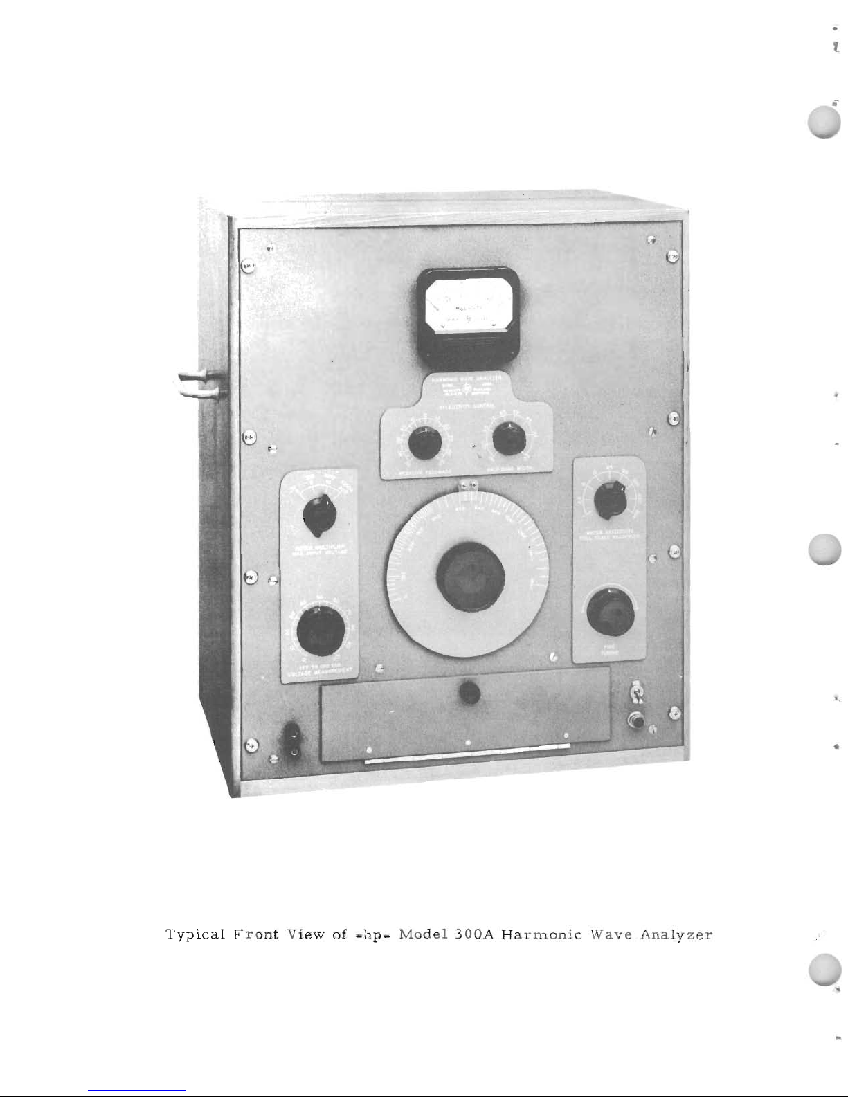
Typical
Front
View
of
-hp-
Model
300A
Harmonic
Wave
Analyzer
'.
Page 11

..
TABLE
OF
CONTENTS
&
INDEX
SPECIFICATIONS.
ACCESSOR'IES
AV
AILAB
LE
CONTROLS
&
TERMINALS.
TUBE
COMPLEMENT
&
TUBE
REPLACEMENTS
1.
PAGE
3
3
4
7
CIRCUIT
DESCRIPTION
General
Input&Phase
Inverter
Circuits.
Modulator
Cir
cuit&Voltage
AInplifier.
Local
Oscillator.
Power
Supply
•
Selective
Amplifier
System.
Voltmeter
Circuit.
CALIBRATION
PROCEDURE
General
Procedure
for
Calibration
.
-'
8
8
9
9
10
10
11
11
11
TEST
PROCEDURE
Instruments
Required
for
Test
Procedure
Preliminary
Tests
&
Adjustments.
1.
Adjustment
of
B+
•
2.
Adjustment
ot:
Local
Oscillator
Injection
Voltage.
3.
Centering
Tuning
Range
of
"F"
Control
•
4.
Check
Os
cillator
Stability
•
S
ele
ctiveAmplifier
Alignment
Heat
Run
Check.
Final
Test
1.
Check&Adjust
Regulated
B+
Voltage.
2.
Check&Adjust
Oscillator
Injection
Voltage
3.
Oscillator
Response
to
Line
Voltage
Change.
4.
Final
Alignment
of
Selective
Amplifier
5.
Adjust
Millivolts
Meter
to
Zero
6.
Centering
Range
of
Control
"C"
7.
Check
for
Carrier
Leakage
•
8.
Check
for
Hum
(Balance
Hum
ControlR159)
•
9.
Check
Resonance
Curves
•
10.Check
Harmonic
Distortion
(Adjust
ControlR117)
11.
Checking
Variable
Selectivity
Contol
12.
Checking
Millivolts
Meter
Tracking.
.13.
Checking
Instrument
Sensitivity
14.
Frequency
Calibration
-
Check&Adjustment
15.
Frequency
Response
Check
16.
Check
Voltage
Calibration.
17.
Checking
Meter
Sensitivity
Control
18.
Checking
Meter
Multiplier
Control
•
19.
Correcting
Unsteady
Millivolts
Meter
Readings
20.
Adding
"CALIBRATION
PROCEDURE"
Labels
21.
Mechanical
Inspection.
22.
Instrument
Bottom
Plate
Replacement.
23.
Completion
of
Final
Test
CIRCUIT
MODIFICATIONS
General
Top
Deck
Modernizing
Procedure.
Parts
Required
for
Complete
Top
Deck
Modernization.
Bottom
Deck
Modification
Procedure
Modification
to
Reduce
Carrier
Leakage.
Power
Supply
Modification
•
Other
Lower
Deck
Modifications
TROUBLE
SHOOTING
General
Trouble
Chart.
13
13
13
13
14
14
14
16
16
16
16
16
16
16
16
16
17
17
18
18
18
18
19
19
20
20
21
21
21
21
21
21
23
23
24
25
25
26
27
29
29
Page 12
2.
TABLE
OF
REPLACEABLE
PARTS
General
..•••.••
Replaceable
Parts
Table
•
List
of
Manufacturers
Code
Letters
for
Replaceable
Parts
Table
;
PAGE
37
38
39
40
41
42
43
44
45
46
47
48
49
51
51
50
..
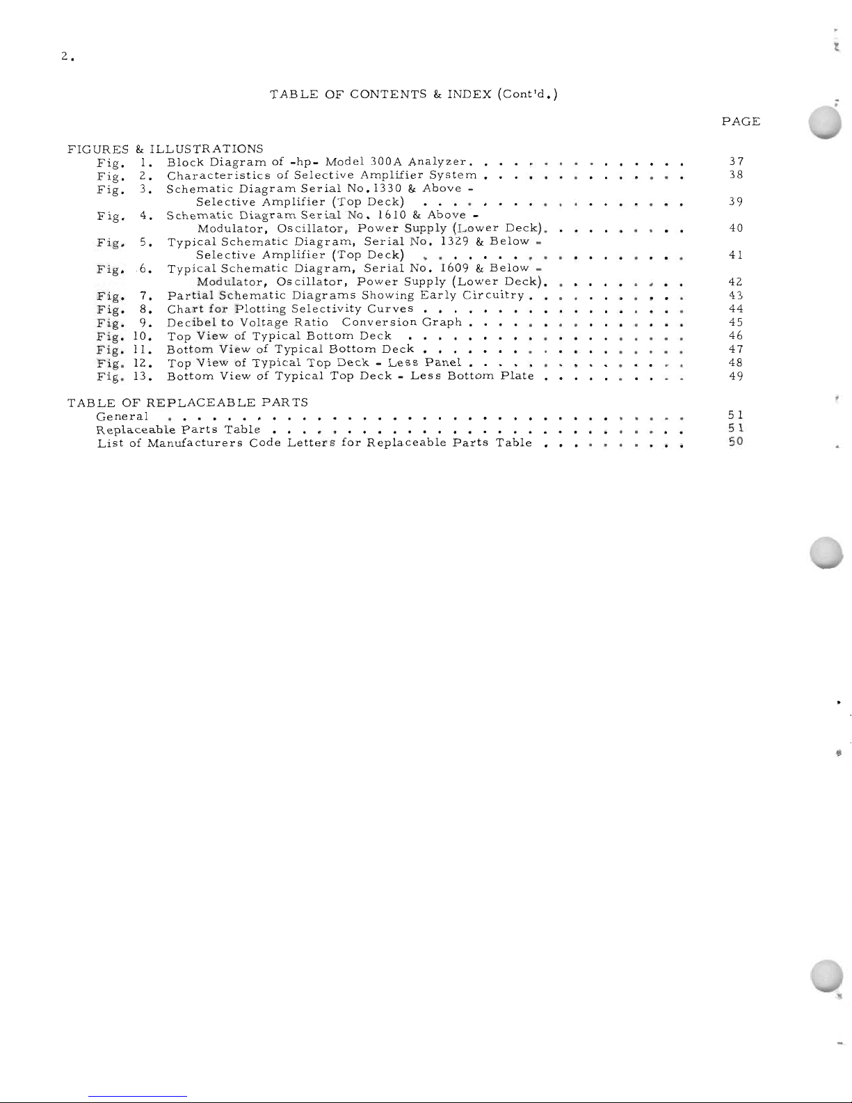
TABLE
OF
CONTENTS
&
INDEX
(Cont'd.)
Fig.
1•
Fig.
2.
Fig.
3.
Fig.
4.
Fig.
5.
Fig.
6.
Fig.
7.
Fig.
8.
Fig.
9.
Fig.
10.
Fig.
11.
Fig.
12.
Fig.
13.
FIGURES
&
ILLUSTRATIONS
Block
Diagram
of
-hp-
Model
300A
Analyzer.
•
Characteristics
of
Selective
Amplifier
System.
Schematic
Diagram
Serial
No.
1330&Above
-
Selective
Amplifier
(Top
Deck)
•••••
Schematic
Diagram
Serial
No.
1610&Above
-
Modulator,
Oscillator,
Power
Supply
(Lower
Deck).
Typical
Schematic
Diagram,
Serial
No.
1329&Below
-
Selective
Amplifier
(Top
Deck)
••••••••••
Typical
Schematic
Diagram,
Serial
No.
1609&Below
-
Modulator,
Oscillator,
Power
Supply
(Lower
Deck).
Partial
Schematic
Diagrams
Showing
Early
Circuitry.
Chart
for
Plotting
Selectivity
Curves
• • .
Decibel
to
Voltage
Ratio
Conversion
Graph
Top
ViewofTypical
Bottom
Deck
• • • •
Bottom
ViewofTypical
Bottom
Deck
• • • •
Top
ViewofTypical
Top
Deck-Less
Panel.
Bottom
ViewofTypical
Top
Deck-Less
Bottom
Plate
.\
\
Page 13
•
3.
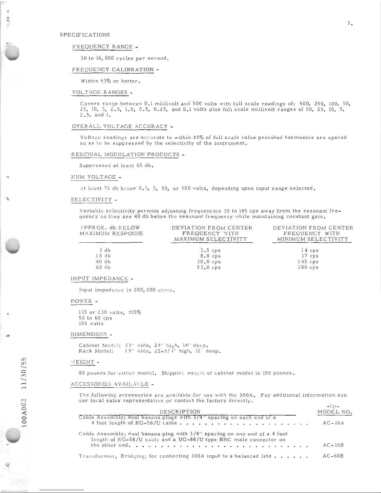
SPECIFICA
TIONS
FREQUENCY
RANGE
-
30to16,000
cycles
per
second.
FREQUENCY
CALIBRATION
-
Within
±3%orbetter.
VOLTAGE
RANGES
-
Covers
range
between
0.1
millivolt
and
500
volts
with
full
scale
readings
of:
500,
250,
100,
50,
25,
10,
5,
2.5,
l.O,
0.5,
0.25,
and
0.1
volts
plus
full
scale
millivolt
ranges
of
50,
25,
10,
5,
2.5,
and
1.
OVERALL
VOLTAGE
ACCURACY
-
Voltage
readings
are
accurate
to
within
±5%offull
scale
value
provided
harmonics
are
spaced
soastobesuppressed
by
the
selectivity
of
the
instrument.
RESIDUAL
MODULATION
PRODUCTS
-
Suppressed
at
least
65
db.
EUM
VOLTAGE
-
l\t
least
73dbbelow
0.5,
:>,
50,
or
500
volts,
depending
upon
input
range
selected.
SELECTIVITY
-
Variable
selectivity
permits
adjusting
frequencies
30to145
cps
away
from
the
resonant
fre-
quency
so
they
are
40dbbelow
th:~
resonant
frequency
while
maintaining
constant
gain.
-\PPROX.
db
BELOW
MAXIMUM
RESPONSE
3
db
10
db
40
db
60
db
INPUT
IMPEDA
TCE -
'DEVIATIO
FROM
CENTER
FREQUENCY
'.'1ITE
MAXIMUM
SELECTIVITY
3.5
cps
8.0
cps
30.0
cps
53.0
cps
DEVIATION
FROM
CENTER
FREQUENCY
WITH
MINIMUM
SELECTIVITY
14
cps
37
cps
145
cps
280
cps
•
Input
impedance
is
200,000
ohms.
POWER
-
115or2.30
volts,
±10%
50to60
cps
105
watts
DIMENSIONS
-
Cabinet
Medel:
Rack
Model:
23"
wide,
24"
high,
14"
deep.
19"
wide,
2.2.-3/1"
high,
12"
deep.
l.1)
l.1)
---
o
<'"'l
---
......
.....
"/EIGHT
-
80
pounds
for
either
model.
Shipping
weight
of
cabinet
model
is
150
pounds.
ACC
ESSOR
IES
,1\
V
IIlLAB
LE
-
The
following
accessories
are
available
for
use
with
the
300A.
For
additional
information
see
our
local
sales
representative
or
contact
the
factory
directly.
l"'J
o
o
«:
o
o
DESCRIPTION
Cable
Assembly;
dual
banana
plugs
wlth
374"
spacmg
on
each
endofa
4
foot
length
of
RG-58/U
cable.
• • • • • • • •
••
•
•••
Cable
Assembly;
dual
banana
plug
with
3/4"
spacing
on
one
endofa 4
foot
length
of
RG-58/U
cilble
andaUG-88/Utype
BNC
male
connector
on
the
other
end.
• • • • • • • • • • • • • • •
Transformer,
Bridging;
for
connecting
300A
inputtoa
balanced
line
-hp-
MODEL
NO.
AC-16A
AC-16B
AC-60B
Page 14
4.
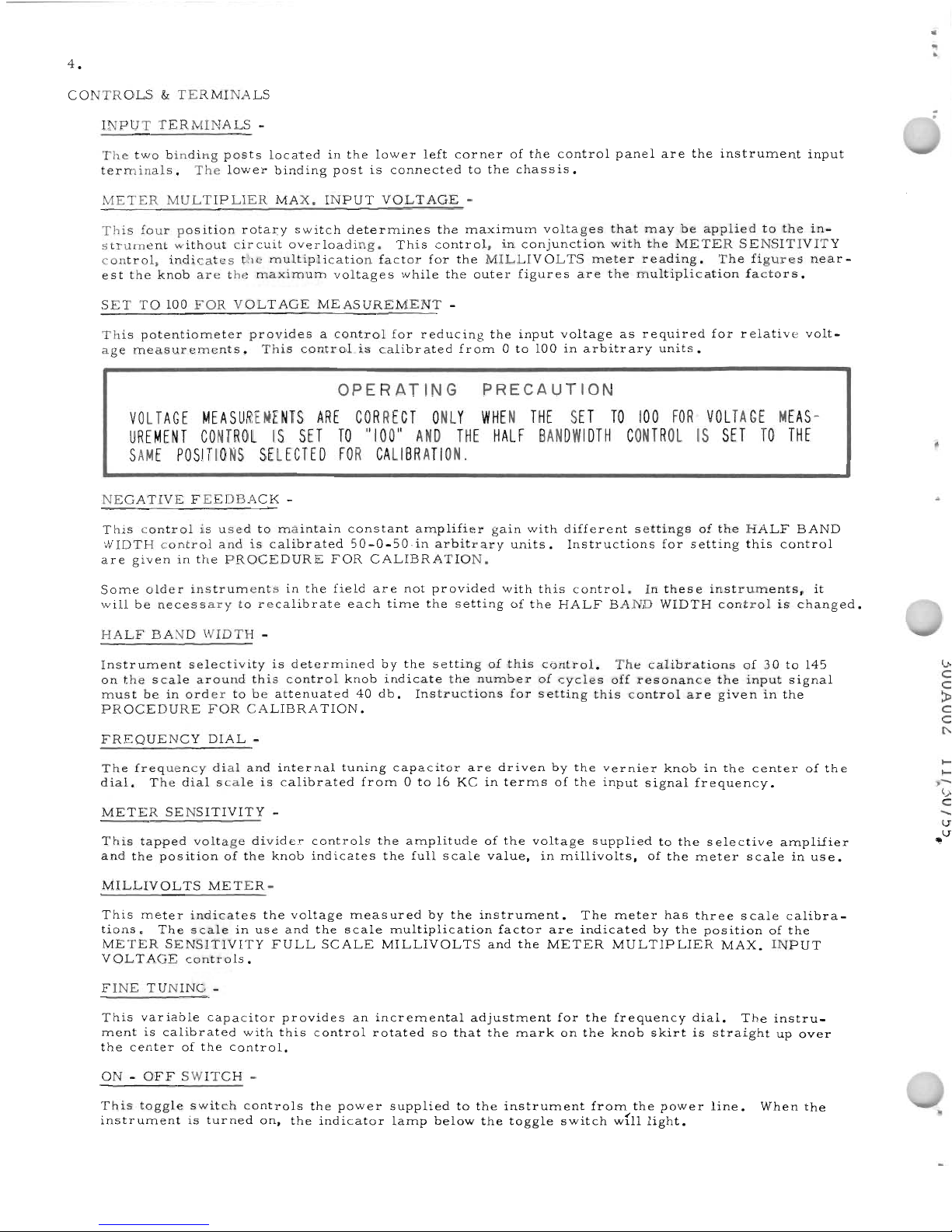
CONTROLS
&
TERMINALS
INPUT
TERMINALS
-
The
two
binding
posts
located
in
the
lower
left
corner
of
the
control
panel
are
the
instrument
input
terminals.
The
lower
binding
post
is
connected
to
the
chassis.
METER
MULTIPLIER
MAX.
INPUT
VOLTAGE
-
This
four
position
rotary
switch
determines
the
maximum
voltages
that
may
be
applied
to
the
in-
strument
without
cir
cuit
overloading.
This
control,
in
conjunction
with
the
METER
SENSITIVITY
control,
indicates
the
multiplication
factor
for
the
MILLIVOLTS
meter
reading.
The
figures
near-
est
the
knob
are
the
maximum
voltages
while
the
outer
figures
are
the
multiplication
factors.
SET
TO
100
FOR
VOLTAGE
MEASUREMENT
-
This
potentiometer
provides
a
control
for
reduCing
the
input
voltage
as
required
for
relative
volt-
age
measurements.
This
control
is
calibrated
from0to
100inarbitrary
units.
OPERATING
PRECAUTION
VOL
TAGE
MEASUREMENTS
ARE
CORRECT
ONLY
WHEN
THE
SET
TO
100
FOR
VOLTAGE
MEAS-
UREMENT
CONTROLISSET
TO
"100"
AND
THE
HALF
BANDWIDTH
CONTROLISSET
TO
THE
SAME
POSITIONS
SELECTED
FOR
CALIBRATION.
NEGATIVE
FEEDBACK
-
This
control
is
used
to
maintain
constant
amplifier
gain
with
different
settings
of
the
HALF
BAND
WIDTH
control
andiscalibrated
50-0-50.in
arbitrary
units.
Instructions
for
setting
this
control
are
given
in
the
PROCEDURE
FOR
CALIBRATION.
Some
older
instruments
in
the
field
are
not
provided
with
this
control.
In
these
instruments,
it
will
be
necessary
to
recalibrate
each
time
the
setting
of
the
HALF
BAND
WIDTH
control
is
changed.
HALF
BAND
WIDTH
-
Instrument
selectivity
is
determined
by
the
setting
of
this
control.
The
calibrations
of30to
145
on
the
scale
around
this
control
knob
indicate
the
number
of
cycles
off
resonance
the
input
signal
must
beinorder
to
be
attenuated
40
db.
Instructions
for
setting
this
control
are
given
in
the
PROCEDURE
FOR
CALIBRATION.
FREQUENCY
DIAL
-
..
;
v;
C
C
>
C
C
r-;
The
frequency
dial
and
internal
tuning
capacitor
are
driven
by
the
vernier
knob
in
the
center
of
the
dial.
The
dial
scale
is
calibrated
from0to16KCinterms
of
the
input
signal
frequency.
METER
SENSITIVITY
-
This
tapped
voltage
divider
controls
the
amplitude
of
the
voltage
supplied
to
the
selective
amplifier
and
the
position
of
the
knob
indicates
the
full
scale
value,
in
millivolts,
of
the
meter
scale
in
use.
MILLIVOLTS
METER-
This
meter
indicates
the
voltage
measured
by
the
instrument.
The
meter
has
three
scale
calibra-
tions.
The
scale
in
use
and
the
scale
multiplication
factor
are
indicated
by
the
position
of
the
METER
SENSITIVITY
FULL
SCALE
MILLIVOLTS
and
the
METER
MULTIPLIER
MAX.
INPUT
VOLTAGE
controls.
FINE
TUNING
-
This
variable
capacitor
provides
an
incremental
adjustment
for
the
frequency
dial.
The
instru-
ment
is
calibrated
with
this
control
rotated
so
that
the
mark
on
the
knob
skirt
is
straight
up
over
the
center
of
the
control.
ON-OFF
SWITCH
-
This
toggle
switch
controls
the
power
supplied
to
the
instrument
from
the
power
line.
When
the
instrument
is
turned
on,
the
indicator
lamp
below
the
toggle
switch
wfll
light.
Page 15
•
U')
U')
-
o
("1"\
-
-
-
N
o
o
~
o
o
("1"\
5.
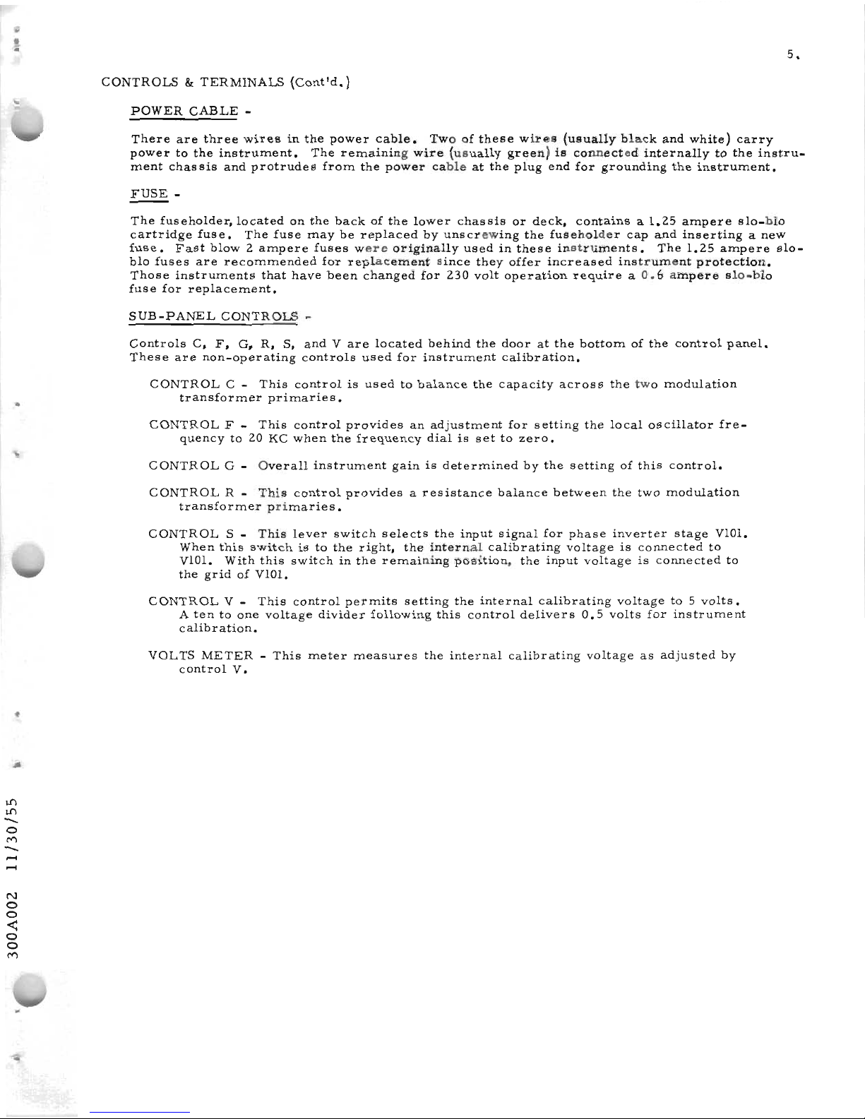
CONTROLS&TERMINALS
(Contld.)
POWER
CABLE
-
There
are
three
wires
in
the
power
cable.
Twoofthese
wires
(usually
black
and
white)
carry
power
to
the
instrument.
The
remaining
wire
(usually
green)
is
connected
internally
to
the
instru-
ment
chassis
and
protrudes
from
the
power
cable
at
the
plug
end
for
grounding
the
instrument.
FUSE
-
The
fuseholder,
located
on
the
backofthe
lower
chas
sis
or
deck,
containsa1.25
ampere
slo-blo
cartridge
fuse.
The
fuse
may
be
replaced
by
unscrewing
the
fuseholder
cap
and
inserting
a
new
fuse.
Fast
blow2ampere
fuses
were
originally
usedinthese
instruments.
The
1.25
ampere
slo-
blo
fuses
are
recommended
for
replacement
since
they
offer
increased
instrument
protection.
Those
instruments
that
have
been
changed
for
230
volt
operation
require
a
0.6
ampere
slo-blo
fuse
for
replacement.
SUB-PANEL
CONTROLS
-
Controls
C,
F,
G.
R,
S,
andVare
located
behind
the
door
at
the
bottom
of
the
control
panel.
These
are
non-operating
controls
used
for
instrument
calibration.
CONTROL
C -
This
control
is
usedtobalance
the
capacity
across
the
two
modulation
transformer
primaries
•
CONTROL
F -
This
control
provides
an
adjustment
for
setting
the
local
oscillator
fre-
quency
to20KC
when
the
frequency
dial
is
settozero.
CONTROL
G -
Overall
instrument
gainisdetermined
by
the
setting
of
this
control.
CONTROL
R -
This
control
provides
a
resistance
balance
between
the
two
modulation
transformer
primaries.
CONTROL
S -
This
lever
switch
selects
the
input
signal
for
phase
inverter
stage
VIOl.
When
this
switch
istothe
right,
the
internal
calibrating
voltage
is
connected
to
VIOl.
With
this
switch
in
the
remaining
position,
the
input
voltage
is
connected
to
the
gridofVIOl.
CONTROL
V -
This
control
permits
setting
the
internal
calibrating
voltage
to5volts.
A
tentoone
voltage
divider
following
this
control
delivers
0.5
volts
for
instrument
calibration.
VOLTS
METER-This
meter
measures
the
internal
calibrating
voltage
as
adjusted
by
control
V.
Page 16

•
..
U1
U1
-
o
C"'\
-
-
-
N
o
o
<
o
o
C"
7.
TUBE
COMPLEMENT
&:
TUBE
REPLACEMENTS
GENERAL
-
Any
tubes
with
RETMA
standard
characteristics
may
be
used
for
replacement
purposes.
However,
as
notedinthe
instructions
that
follow,
useofa
selected
tube
will
improve
instrument
performance
in
some
cases.
The
300Aisa
high
gain
instrument.
Tubes
that
are
microphonic
or
have
relatively
high
heater
to
cathode
leakage
are
not
desirable.
The
tube type
used
for
some
of
the
stages
in
the
300A
have
varied
with
time.
In
some
cases
use
of
a
later
tube
typeisrecommended
but
not
neces
sary.
Ifindoubt,
replace
tubes
with
the
same
type
foundinthe
instrument.
The
number
of
adjustments
required
will
depend
upon
the
tube
replaced.
The
specific
tests
and/or
adjustments
are
given
in
the
chart
that
follows.
This
chart
also
shows
where
the
procedures
for
these
tests
and
adjustments
can
be
foundinthe
TEST
PROCEDURE
section
of
this
manual.
CIRCUIT
ORIGINAL
RECOMMENDED
TESTS,
ADJUSTMENTS,
AND/OR
REFERENCE
TUBE
TYPE
REP
LACEMENT
SPECIAL
NOTES
VI
thru
V8
6SJ7
6SJ7
FINAL
TEST
procedure
steps8and
9.
Low
microphonic
tubes
are
best.
V9
6F8
or
6F8
or
6SN7
Replace
with
same
type
asininstrument.
6SN7
FINAL
TEST
step
3.
VIO
6H6
Aged
6H6
Select
tube
giving
minimum
change
in
zero
setting
between
instrument
on
and
off
with
no
input
signal.
Complete
FINAL
TEST
step
3.
F 101 2
amp
fast
1.
25
amp
Slo-blo
fuse
gives
better
instrument
pro-
blow
or
1.25
slo-blo
tection.
Use
different
fuse
for
230
volt
amp
slo
-blo
operation
as
noted
under
FUSEinthe
for
115
V.
CONTROLS
&:
TERMINALS
section.
operation.
R140
lamp
3
watts,
115
10
watts
FINAL
TEST
step
2.
See
step1of
OTHER
volts
or
230
volts
LOWER
DECK
MODIFICATIONS
under
10
watts,
BOTTOM
DECK
MODIFICATION
PRO-
230
volts
CEDURE
in
CIRCUIT
MODIFICATIONS
section.
VIOl
6SJ7
6SJ7
FINAL
TEST
procedure
steps
3,
6,
8,
&:
10.
Useatube
with
low
microphonics
and
check
fora"hump"
in
the
resonance
V
102
&:
6SJ7
6SJ7
selected
curves
as
directed
in
FINAL
TEST
pro-
V 103
asamatched
cedure
step
9.
pair.
Vl04
6SJ7
6SJ7
FINAL
TEST
step
3.
Check
for
low
microphonics,
hum,
and
60
cps
"hump".
FINAL
TESTstep
9a.
V
105
6J7
6J7
Changing
either
tube
will
not
cause
appre-
ciable
change
in
frequency
oroscillator
inj
ection
voltage.
Check
by
repeating
steps
2,
3,
8,
10,
and14of
FINAL
TEST.
VI06
6F6
6F6
Os
cillator
output
should
be
stable.
Tubes
should
be
non-rnicrophonic.
Page 17
8.
TUBE
COMPLEMENT
lit
TUBE
REPLACEMENTS
(Cont'd.)
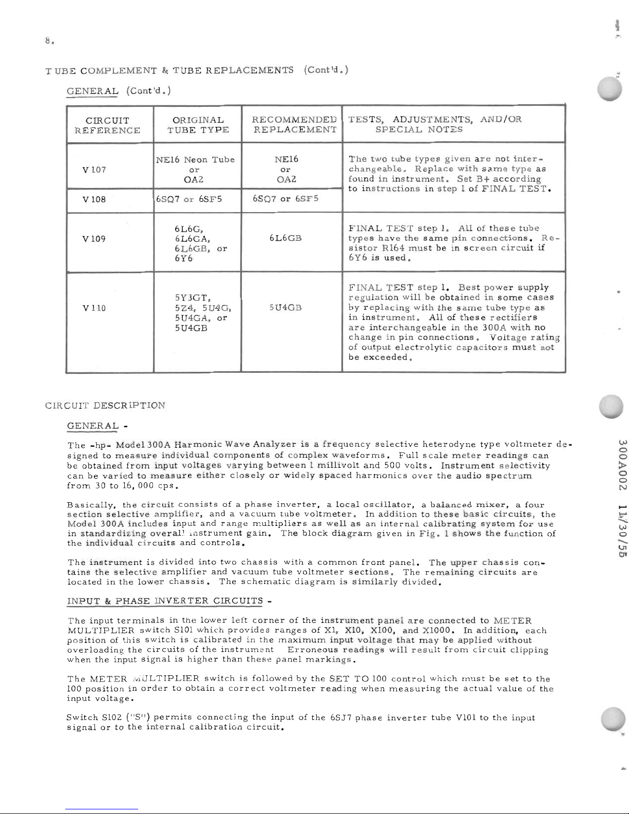
GENERAL
(Cont'd.)
CIRCUIT
ORIGINAL
RECOMMENDED
TESTS,
ADJUSTMENTS,
AND/OR
REFERENCE
TUBE
TYPE
REPLACEMENT
SPECIAL
NOTES
NE16
Neon
Tube
NE16
The
two
tube
types
given
are
not
inter-
V
107
or
or
changeable.
Replace
with
same
type
as
OA2
OA2
foundininstrument.
Set
B+
according
to
instructions
in
step1of
FINAL
TEST.
V
108
6SQ7
or
6SF5
6SQ7
or
6SF5
6L6G,
FINAL
TEST
step
1.
Allofthese
tube
V
109
6L6GA,
6L6GB
types
have
the
same
pin
connections.
Re-
6L6GB,
or
sistor
R164
must
beinscreen
circuit
if
6Y6
6Y6isused.
FINAL
TEST
step
1.
Best
power
supply
5Y3GT,
regulation
will
be
obtained
in
some
cases
VUO
5Z4,
5U4G,
5U4GB
by
replacing
with
the
same
tube
type
as
5U4GA,
or
in
instrument.
Allofthese
rectifiers
5U4GB
are
interchange;;ible
in
the
300A
with
no
change
in
pin
connections.
Voltage
rating
of
output
electrolytic
capacitors
must
not
be
exceeded.
CIRCUIT
DESCRIPTION
GENERAL
-
.
.
The
-hp-
Mode1300A
Harmonic
Wave
Analyzer
isafrequency
selective
heterodyne
type
voltmeter
signed
to
measure
individual
components
of
complex
waveforms.
Full
scale
meter
readings
can
be
obtained
from
input
voltages
varying
between1millivolt
and
500
volts.
Instrument
selectivity
can
be
varied
to
measure
either
closely
or
widely
spaced
harmonics
over
the
audio
spectrum
from
30to16,
000
cps.
Basically,
the
circuit
consists
ofaphase
inverter,
a
local
oscillator,
a
balanced
mixer,
a
four
section
selective
amplifier,
andavacuum
tube
voltmeter.
In
addition
to
these
basic
circuits,
the
Model
300A
includes
input
and
range
multipliers
as
well
as
an
internal
calibrating
system
for
use
in
standardizing
overall
instrument
gain.
The
block
diagram
giveninFig.1shows
the
function
of
the
individual
circuits
and
controls.
The
instrument
is
divided
into
two
chassis
withacommon
front
panel.
The
upper
chassis
con-
tains
the
selective
amplifier
and
vacuum
tube
voltmeter
sections.
The
remalnlng
circuits
are
located
in
the
lower
chassis.
The
schematic
diagram
is
similarly
divided.
INPUT
lit
PHASE
INVERTER
CIRCUITS
-
The
input
terminals
in
the
lower
left
corner
of
the
instrument
panel
are
connected
to
METER
MULTIPLIER
switch
SlOl
which
provides
ranges
of
Xl,
XlO,
XlOO,
and
XlOOO.
In
addition,
each
position
of
this
switch
is
calibrated
in
the
maximum
input
voltage
that
may
be
applied
without
overloading
the
circuits
of
the
instrument.
Erroneous
readings
will
result
from
circuit
clipping
when
the
input
signal
is
higher
than
these
panel
markings.
The
METER
MULTIPLIER
switch
is
followed
by
the
SET
TO
100
control
which
must
be
settothe
100
position
in
order
to
obtainacorr
ect
voltmeter
reading
when
measuring
the
actual
value
of
the
input
voltage.
Switch
5102
("S")
permits
connecting
the
inputofthe
6SJ7
phase
inverter
tube
VIOltothe
input
signal
ortothe
internal
calibration
circuit.
de-
l.U
0
0
~
0
0
N
-
:-
~
l.U
0
-
U1
C11
..
Page 18
lI)
lI)
-
o
l""'I
-
.....
.....
N
o
o
<
o
o
l""'I
9.
CIRCUIT
DESCRIPTION
(Cont'd.)
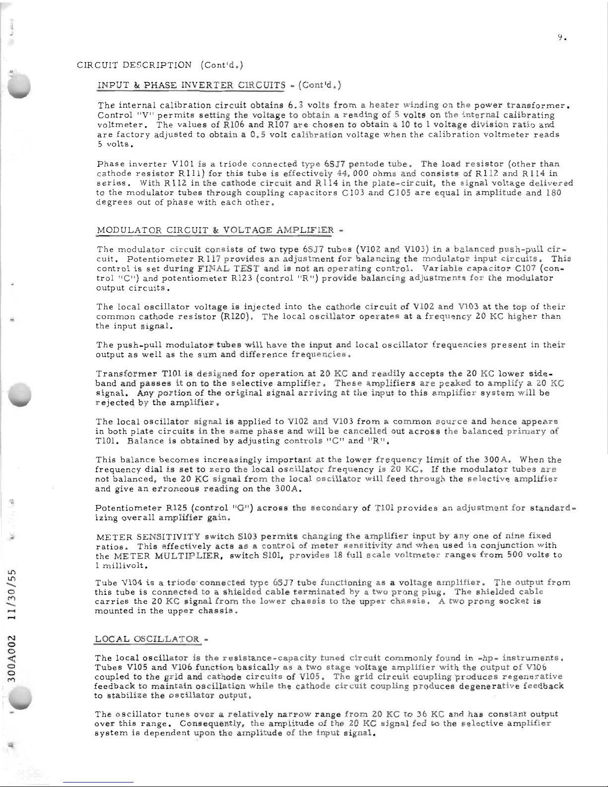
INPUT&PHASE
INVERTER
CIRCUITS-(Cont'd.)
The
internal
calibration
circuit
obtains
6.3
volts
fromaheater
winding
on
the
power
transformer.
Control
"V"
permits
setting
the
voltage
to
obtainareading
of5volts
on
the
internal
calibrating
voltmeter.
The
values
of
Rl06
and
Rl07
are
chosen
to
obtain
a 10to1
voltage
division
ratio
and
are
factory
adjusted
to
obtaina0.5
volt
calibration
voltage
when
the
calibration
voltmeter
reads
5
volts.
Phase
inverter
VIOlisa
triode
connected
type
6SJ7
pentode
tube.
The
load
resistor
(other
than
cathode
resistor
RIll)
for
this
tubeiseffectively
44,000
ohms
and
consists
of
Rl12
and
Rl14
in
serie-s.
With
Rl12
in
the
cathode
circuit
and
Rll4
in
the
plate-circuit,
the
signal
voltage
delivered
to
the
modulator
tubes
through
coupling
capacitors
CI03
and
Cl05
are
equalinamplitude
and
180
degrees
outofphase
with
each
other.
MODULATOR
CIRCUIT
&
VOLTAGE
AMPLIFIER
-
The
modulator
circuit
consists
of
two
type
6SJ7
tubes
(Vl02
and
Vl03)ina
balanced
push-pull
cir-
cuit.
Potentiometer
R 117
providesan
adjustment
for
balancing
the
modulator
input
circuits.
This
control
is
set
during
FINAL
TEST
andisnotanoperating
control.
Variable
capacitor
CI07
(con-
trol
"C")
and
potentiometer
R123
(control
"R")
provide
balancing
adjustments
for
the
modulator
output
circuits.
The
local
oscillator
voltage
is
injected
into
the
cathode
circuit
of
Vl02
and
Vl03atthe
topoftheir
common
cathode
resistor
(R120).
The
local
oscillator
operates
atafrequency
20
KC
higher
than
the
input
signal.
The
push-pull
modulato1l'
tubes
will
have
the
input
and
local
oscillator
frequencies
present
in
their
output
as
well
as
the
sum
and
difference
frequencies.
Transformer
TlOlisdesigned
for
operation
at20KC
and
readily
accepts
the
20
KC
lower
side-
band
and
passes
itonto
the
selective
amplifier.
These
amplifiers
are
peaked
to
amplifya20
KC
signal.
Any
portion
of
the
original
signal
arriving
at
the
inputtothis
amplifier
system
will
be
rejected
by
the
amplifier.
The
local
oscillator
signal
is
applied
to
Vl02
and
Vl03
fromacommon
source
and
hence
appears
in
both
plate
circuits
in
the
same
phase
and
will
be
cancelled
out
across
the
balanced
primary
of
TlOl.
Balance
is
obtained
by
adjusting
controls
"C"
and
"R".
This
balance
becomes
increasingly
important
at
the
lower
frequency
limit
of
the
300A.
When
the
frequency
dial
is
settozero
the
local
oscillator
frequency
is
20
KC.
If
the
modulator
tubes
are
not
balanced,
the
20
KC
signal
from
the
local
oscillator
will
feed
through
the
selective
amplifier
and
give
an
erroneous
reading
on
the
300A.
Potentiometer
R125
(control
"G")
across
the
secondary
of
TlOl
provides
an
adjustment
for
standard-
izing
overall
amplifier
gain.
METER
SENSITIVITY
switch
Sl03
permits
changing
the
amplifier
input
by
anyone
of
nine
fixed
ratios.
This
effectively
acts
asacontrol
of
meter
sensitivity
and
when
used
in
conjunction
with
the
METER
MULTIPLIER,
switch
SlOl,
provides
18
full
scale
voltmeter
ranges
from
500
volts
to
1
millivolt.
Tube
Vl04isa
triode'
connected
type
6SJ7
tube
functioning
asavoltage
amplifier.
The
output
from
this
tube
is
connected
toashielded
cable
terminated
byatwo
prong
plug.
The
shielded
cable
carries
the
20
KC
signal
from
the
lower
chassis
to
the
upper
chassis.
A
two
prong
socket
is
mounted
in
the
upper
chassis
•
LOCAL
OSCILLATOR
-
The
local
oscillator
is
the
resistance-capacity
tuned
circuit
commonly
foundin-hp-
instruments.
Tubes
Vl05
and
Vl06
function
basically
asatwo
stage
voltage
amplifier
with
the
output
of
Vl06
coupled
to
the
grid
and
cathode
circuits
of
Vl05.
The
grid
cir
cuit
coupling
produces
regenerative
feedback
to
maintain
oscillation
while
the
cathode
circuit
coupling
produces
degenerative
feedback
to
stabilize
the
oscillator
output.
The
oscillator
tunes
overarelatively
narrow
range
from
20
KCto36
KC
and
has
constant
output
over
this
range.
Consequently,
the
amplitude
of
the
20
KC
signal
fedtothe
selective
amplifier
system
is
dependent
upon
the
amplitude
of
the
input
signal.
Page 19
10.
CIHCUIT
DESCrnPTlON
(Cont'd.)
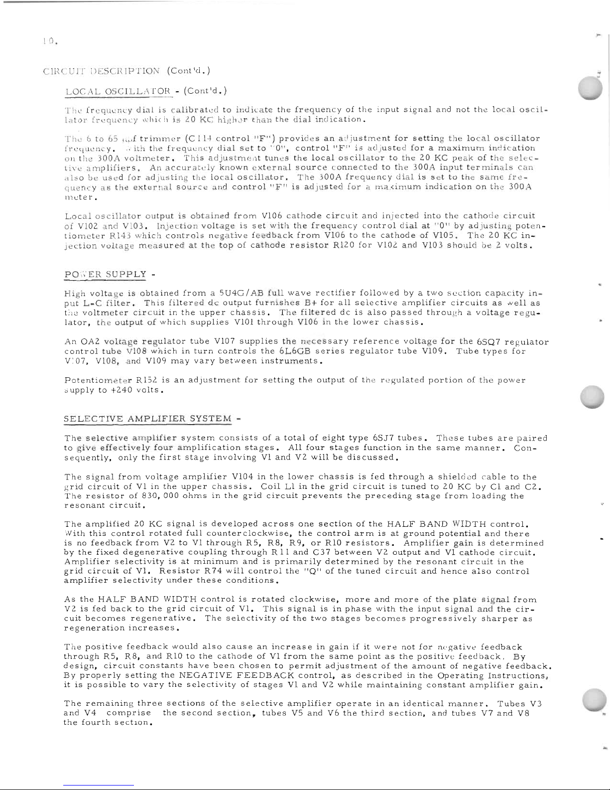
LOCAL
OSCILLATOR
-
(Cont'd.)
The
frequency
dial
is
calibrakd
to
indicate
the
frequency
of
the
input
signal
and
not
the
local
oscil-
lator
frequL'ncy
which
is
lO
KC
high,"r
than
the
dial
indication.
The6to65L,,.,f
trimmer
(C
ll-l
control
"F")
provides
an
acijustment
for
setting
the
local
oscillator
frequency
...
ith
the
frequency
dial
set
to
"0".
control
"F"
is
adjusted
foramaximum
indication
on
the
300A
voltmeter.
This
adjustmr~'1t
tunes
the
local
oscillator
to
the
20
KC
peak
of
the
selec-
tive
amplifiers.
An
accurately
known
external
source
connected
to
the
300A
input
terminals
can
illso
be
used
for
adjusting
the
local
oscillator.
The
300A
frequency
dial
is
set
to
the
same
fre-
quency
as
the
external
source
and
control
"F"
is
adjusted
forama.<:imum
indication
on
the
300A
111eter.
Lo
caloscilla
tor
output
is
obtained
fr
om
VIa6cathodecircuit
and
inj
ected
into
the
cathodecir
cuit
of
VI02
and
VI03.
Injection
voltage
is
set
with
the
frequency
control
dial
at
"a"
by
adjusting
poten-
tiometer
R143
which
controls
negative
feedback
from
VI06tothe
cathode
of
VI05.
The
20
KC
in-
jection
voltage
measured
at
the
top
of
cathode
resistor
Rl20
for
VI02-
and
VI03
should
be2volts.
PO,,'ER
SUPPLY
-
High
voltage
is
obtained
froma5U4G/AB
full
wave
rectifier
followed
byatwo
section
capacity
in-
put
L-C
filter.
This
filtered
dc
output
furnishes
B+
for
all
selective
amplifier
circuits
as
..veIl
as
the
voltmeter
circuit
in
the
upper
chassis.
The
filtered
dcisalso
passed
through
a
voltage
regu-
lator,
the
output
of
which
supplies
VIOl
through
VI06inthe
lower
chassis.
An
OA2
voltage
regulator
tube
VI07
supplies
the
necessary
reference
voltage
for
the
6SQ7
regulator
control
tube
VI08
which
in
turn
controls
the
6L6GB
series
regulator
tube
VI09.
Tube
types
for
VI07, VI08.
and
VI09
may
vary
between
instruments.
Potentiometer
R152isan
adjustment
for
setting
the
output
of
the
regulated
portion
of
the
power
supply
to
+240
volts.
SELECTIVE
AMPLIFIER
SYSTEM
-
The
selective
amplifier
system
consists
ofatotal
of
eight
type
65J7
tubes.
to
give
effectively
four
amplification
stages.
All
four
stages
function
in
the
sequently,
only
the
first
stage
involving
VI
and
V2
will
be
discussed.
These
tubes
are
paired
same
manner.
Con-
The
signal
from
voltage
amplifier
Vl04inthe
lower
chassis
is
fed
through
a
shielded
cable
to
the
grid
circuit
ofVIin
the
upper
chassis.
Coil
LIinthe
grid
circuit
is
tuned
to
20
KC
by
CI
and
C2.
The
resistor
of
830,
000
ohms
in
the
grid
circuit
prevents
the
preceding
stage
from
loading
the
resonant
circuit.
The
amplified
20
KC
signal
is
developed
across
one
section
of
the
HALF
BAND
WIDTH
control.
With
this
control
rotated
full
counterclockwise,
the
control
arm
isatground
potential
and
there
is
no
feedback
from
V2toVI
through
R5, R8,R9,
or
RIO
resistors.
Amplifier
gainisdetermined
by
the
fixed
degenerative
coupling
through
R11and
C37
between
V2
output
and
VI
cathode
circuit.
Amplifier
selectivity
isatminimum
andisprimarily
determined
by
the
resonant
circuit
in
the
grid
circuit
of
VI.
Resistor
R74will
control
the
IIQIIofthe
tuned
circuit
and
hence
also
control
amplifier
selectivity
under
these
conditions.
As
the
HALF
BAND
WIDTH
control
is
rotated
clockwise,
more
and
more
of
the
plate
signal
from
V2isfed
back
to
the
grid
circuit
of
VI.
This
signal
isinphase
with
the
input
signal
and
the
cir-
cuit
becomes
regenerative.
The
selectivity
of
the
two
stages
becomes
progressively
sharper
as
regeneration
increases.
The
positive
feedback
would
also
cause
an
increase
in
gainifit
were
not
for
negative
feedback
through
R5,
R8,
and
RIOtothe
cathode
ofVIfrom
the
same
point
as
the
positive
feedback.
By
design,
circuit
constants
have
been
chosen
to
permit
adjustment
of
the
amount
of
negative
feedback.
By
properly
setting
the
NEGATIVE
FEEDBACK
control,
as
described
in
the
Operating
Instructions,
itispossible
to
vary
the
selectivity
of
stages
VI
and
V2
while
maintaining
constant
amplifier
gain.
The
remaining
three
sections
of
the
selective
amplifier
operate
inanidentical
manner.
Tubes
V3
and
V4
comprise
the
second
section,
tubes
V5
and
V6
the
third
section,
and
tubes
V7
and
V8
the
fourthsectlon.
Page 20
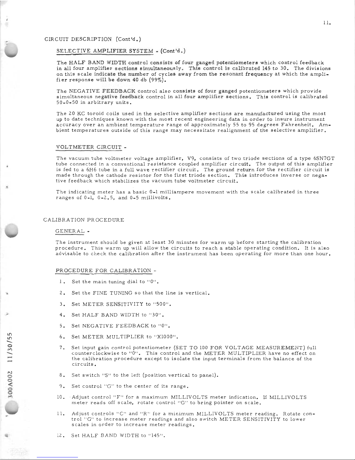
l1"\
l1"\
-
a
r')
-
.....
.....
N
a
a
~
a
a
r')
11.
CIRCUIT
DESCRIPTION
(Cont'd.)
SELECTIVE
AMPLIFIER
SYSTEM-(Cont'd.)
The
HALF
BAND
WIDTH
control
consists
of
four
ganged
potentiometers
which
control
feedback
in
all
four
amplifier
sections
simultaneously.
This
control
is
calibrated
145to30.
The
divisions
on
this
scale
indicate
the
number
of
cycles
away
from
the
resonant
frequency
at
which
the
ampli-
fier
response
will
be
down
40db(99%).
The
NEGATIVE
FEEDBACK
control
also
consists
of
four
ganged
potentiometers
which
provide
simultaneous
negative
feedback
control
in
all
four
amplifier
sections.
This
control
is
calibrated
50-0-50
in
arbitrary
units.
The
20
KC
toroid
coils
used
in
the
selective
amplifier
sections
are
manufactured
using
the
most
uptodate
techniques
known
with
the
most
recent
engineering
data
in
order
to
insure
instrument
accuracy
over
an
ambient
temperature
range
of
approximately
55to95
degrees
Fahrenheit.
Am-
bient
temperatures
outside
of
this
range
may
necessitate
realignment
of
the
selective
amplifier.
VOLTMETER
CIRCUIT
-
The
vacuum
tube
voltmeter
voltage
amplifier,
V9,
consists
of
two
triode
sections
ofatype
6SN7GT
tube
connected
inaconventional
resistance
coupled
amplifier
circuit.
The
output
of
this
amplifier
is
fedtoa
6H6
tube
inafull
wave
rectifier
circuit.
The
ground
return
for
the
rectifier
circuit
is
made
through
the
cathode
resistor
for
the
first
triode
section.
This
introduces
inverse
or
nega-
tive
feedback
which
stabilizes
the
vacuum
tube
voltmeter
circuit.
The
indicating
meter
hasabasic
0-1
milliampere
movement
with
the
scale
calibrated
in
three
ranges
of
0-1,
0-2.5,
and
0-5
millivolts.
CALIBRA
nON
PROCEDURE
GENERAL
-
The
instrument
should
be
given
at
least
30
minutes
for
warm
up
before
starting
the
calibration
procedure.
This
warm
up
will
allow
the
circuits
to
reachastable
operating
condition.
It
is
also
advisable
to
check
the
calibration
after
the
instrument
has
been
operating
for
more
than
one
hour.
PROCEDURE
FOR
CALIBRATION
-
1.
Set
the
main
tuning
dialto"0".
2.
Set
the
FINE
TUNING
so
that
the
line
is
vertical.
3.
Set
METER
SENSITIVITY
to
"SaO".
4.
Set
HALF
BAND
WIDTHto"30".
5.
Set
NEGATIVE
FEEDBACK
to
"0".
6.
Set
METER
MULTIPLIER
to
"XIOOO".
7.
Set
input
gain
control
potentiometer
(SET
TO
100
FOR
VOLTAGE
MEASUREMENT)
full
counterclockwise
to
"a".
This
control
and
the
METER
MULTIPLIER
have
no
effect
on
the
calibration
procedure
except
to
isolate
the
input
terminals
from
the
balance
of
the
circuits.
8.
Set
switch
"S"tothe
left
(position
vertical
to
panel).
9.
Set
control
"G"tothe
center
of
its
range.
10.
-Adjust
control
"F"
foramaximum
MILLIVOLTS
meter
indication.
If
MILLIVOLTS
meter
reads
off
scale,
rotate
control
"G"tobring
pointer
on
scale.
11.
Adjust
controls
"C"
and
"R"
foraminimum
MILLIVOLTS
meter
reading.
Rotate
con-
trol
"G"toincrease
meter
readings
and
also
switch
METER
SENSITIVITY
to
lower
scales
in
order
to
increase
meter
readings.
12.
Set
HALF
BAND
WIDTHto"145".
Page 21
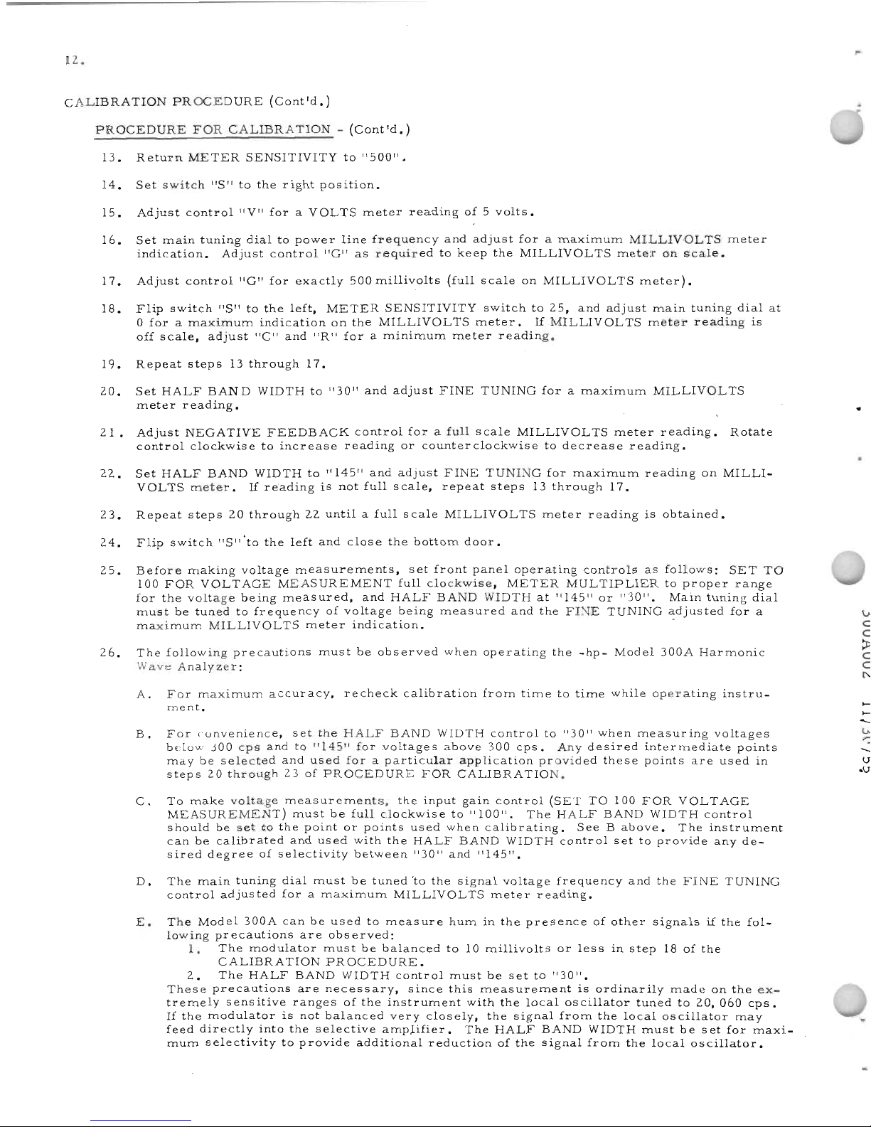
12.
CALIBRATION
PROCEDURE
(Cont'd.)
PROCEDURE
FOR
CALIBRATION
-
(Cont'd.)
13.
Return
METER
SENSITIVITY
to
"500".
14.
Set
switch
"S"tothe
right
position.
15.
Adjust
control
"V"
foraVOLTS
meter
reading
of5volts.
16.
Set
main
tuning
dial
to
power
line
frequency
and
adjust
foramaximum
MILLIVOLTS
meter
indication.
Adjust
control
"G"
as
required
to
keep
the
MILLIVOLTS
meter
on
scale.
17.
Adjust
control
"G"
for
exactly
500
millivolts
(full
scale
on
MILLIVOLTS
meter).
18.
Flip
switch
"S"tothe
left,
METER
SENSITIVITY
switch
to
25,
and
adjust
main
tuning
dial
at
o
foramaximum
indication
on
the
MILLIVOLTS
meter.
If
MILLIVOLTS
meter
reading
is
off
scale,
adjust
"C"
and
"R"
foraminimum
meter
reading.
19.
Repeat
steps
13
through
17.
20.
Set
HALF
BAND
WIDTH
to
"30"
and
adjust
FINE
TUNING
foramaximum
MILLIVOLTS
meter
reading.
21.
Adjust
NEGATIVE
FEEDBACK
control
forafull
scale
MILLIVOLTS
meter
reading.
Rotate
control
clockwise
to
increase
reading
or
counterclockwise
to
decrease
reading.
22.
Set
HALF
BAND
WIDTH
to
"145"
and
adjust
FINE
TUNING
for
maximum
reading
on
MILLI-
VOLTS
meter.
If
reading
is
not
full
scale,
repeat
steps
13
through
17.
23.
Repeat
steps
20
through
22
untilafull
scale
MILLIVOLTS
meter
reading
is
obtained.
24.
Flip
switch
"S,,'to
the
left
and
close
the
bottom
door.
25.
Before
making
voltage
measurements,
set
front
panel
operating
controls
as
follows:
SET
TO
100
FOR
VOLTAGE
MEASUREMENT
full
clockwise,
METER
MULTIPLIER
to
proper
range
for
the
voltage
being
measured,
and
HALF
BAND
WIDTH
at
"145"
or
"30".
Main
tuning
dial
must
be
tuned
to
frequency
of
voltage
being
measured
and
the
FINE
TUNING
adjusted
for
a
maximum
MILLIVOLTS
meter
indication.
-
26.
The
following
precautions
must
be
observed
when
operating
the
-hp-
Model
300A
Harmonic
Wave
Analyzer:
A.
For
maximum
accuracy,
recheck
calibration
from
time
to
time
while
operating
instru-
ment.
B.
For
convenience,
set
the
HALF
BAND
WIDTH
control
to
"30"
when
measuring
voltages
below
300
cps
andto"145"
for
voltages
above
300
cps.
Any
desired
intermediate
points
may
be
selected
and
used
foraparticular
application
provided
these
points
are
used
in
steps
20
through
23ofPROCEDURE
FOR
CALIBRATION.
C.
To
make
voltage
measurements,
the
input
gain
control
(SET
TO
100
FOR
VOLT
AGE
MEASUREMENT)
must
be
full
clockwise
to
"100".
The
HALF
BAND
WIDTH
control
should
be
settothe
point
or
points
used
when
calibrating.
SeeBabove.
The
instrument
can
be
calibrated
and
used
with
the
HALF
BAND
WIDTH
control
set
to
provide
any
de-
sired
degree
of
selectivity
between
"30"
and
"145".
D.
The
main
tuning
dial
must
be
tuned
'to
the
signal
voltage
frequency
and
the
FINE
TUNING
control
adjusted
foramaximum
MILLIVOLTS
meter
reading.
E.
The
Model
300A
can
be
used
to
measure
huminthe
presence
of
other
signals
if
the
fol-
lowing
precautions
are
observed:
1.
The
modulator
must
be
balanced
to
10
millivolts
or
less
in
step
18ofthe
CALIBRATION
PROCEDURE.
2.
The
HALF
BAND
WIDTH
control
must
be
setto"30".
These
precautions
are
necessary,
since
this
measurement
is
ordinarily
made
on
the
ex-
tremely
sensitive
ranges
of
the
instrument
with
the
local
oscillator
tuned
to
20,060
cps.
If
the
modulator
is
not
balanced
very
closely,
the
signal
from
the
local
oscillator
may
feed
directly
into
the
selective
amplifier.
The
HALF
BAND
WIDTH
must
be
set
for
maxi-
mum
selectivity
to
provide
additional
reduction
of
the
signal
from
the
local
oscillator.
VJ
o
o
~
o
o
N
.....
.....
-
VJ
'?
-
\Jl
.,\Jl
Page 22

13.
CALIBRATION
PROCEDURE
(Cont'd.)
PROCEDURE
FOR
CALIBRATION
-
(Co.l.t'd.)
F.
A
20
KC
external
signal
source
operating
near
the
300A
may
radiate
a
signal
directly
into
the
selective
amplifier
of
the
300A
and
produce
an
erroneous
MILLIVOLTS
meter
reading
orabeat.
RANGE
OF
REALIGNMENT
APPROXIMATE
AMBIENT
TEMPERATURE
AMBIENT
TEMPERATURES
MAY
REOUIRE
THIS
INSTRUMENTISACCURATE
WITHIN
THE
55
TO95DEGREES
FAHRENHEIT.
OTHER
OF
THE
SELECTIVE
AMPLIFIER.
TEST
PROCEDURE
INSTRUMENTS
REQUIRED
FOR
TEST
PROCEDURE
-
•
1.
A
constant
frequency
and
voltage
sine
wave
source
delivering
20
KC
with
not
more
than
1%
distortion.
The
-hp-
Model
200CD
''vide
Range
Oscillator
is
recommended.
A
signal
gen-
erator
with
an
output
attenuator
such
as
-hp-
Models
205A,
205AG, 205AH,
or
650A
can
al-
so
be
used
•
2.
A
frequency
measuring
device
such
as
an
-hp-
Model
521,
522,
523,
or
524
Electronic
Counter
is
recommended.
An
-hp-
Model
lOOCor100D
Secondary
Frequency
Standard
used
in
conjunction
with
an
oscilloscope
will
also
serve
the
same
purpose.
3.
A
pure
sine
wave
source
covering
the
approximate
range
from
100to6,300
cps
with
extremely
low
distortion
is
needed.
The
-hp-
Model
206A
Audio
Signal
Generator
followed
byapure
wave'
filter
is
recommended.
4.
Adcvoltmeter
such
as
-hp-
Model
410B.
5.
A
constantly
variable
transformer
for
line
voltage
control.
6.
Anacvoltmeter
such
as
-hp-
Model
330,
400AB,
or
400D.
7.
An
oscilloscope
with
response
upto36
KC.
IMPORTANT
TEST
PROCEDURES
MUSTBEPERFORMEDINTHE
SE~UENCE
GIVEN.
PRELIMINARY
TESTS&ADJUSTMENTS
-
The
instrument
should
be
turned
onatleast
an
hour
before
making
these
adjustments.
Set
the
line
voltage
to
115
volts
for
all
tests
unless
otherwise'instructed.
Unless
otherwise
designated,
refer
to
Figs.
3
and4for
circuit
references.
1.
Set
the
regulated
dc
voltage
at
cathode
pin8of
Vl09
to
240
volts
by
adjusting
control
potentio-
meter
R152.
This
control
will
not
be
found
in
some
older
instruments
anditwill
be
neces-
sary
to
pad
resistor
R50orR5l
shown
in
Fig.
7Ctoadjust
for
240
volts.
The
output
of
the
regulated
supply
should
stay
within
the
limits
of
238
and
242
volts
when
the
line
voltage
is
varied
between
102
al]-d
128
volts.
2.
Set
main
tuning
dial
to
zero
and
engraved
line
on
FINE
TUNING
knobina
vertical
position.
Measure
local
oscillator
injection
voltage
at
cathode
pin5of
Vl02
or
Vl03.
The
20
KC
volt-
age
measured
should
be2volts.
Adjust
potentiometer
R
143
until
a 2
volt
reading
is
obtained
on
the
voltmeter.
If
necessary,
selectacathode
lamp
(R140)tobring
the
oscillator
level
within
the
adjustment
range
ofR143.
Older
instruments
haveafixed
resistor
in
place
of
this
control
and
adjustment
is
made
by
padding
the
value
of
the
fixed
resistor.
Page 23
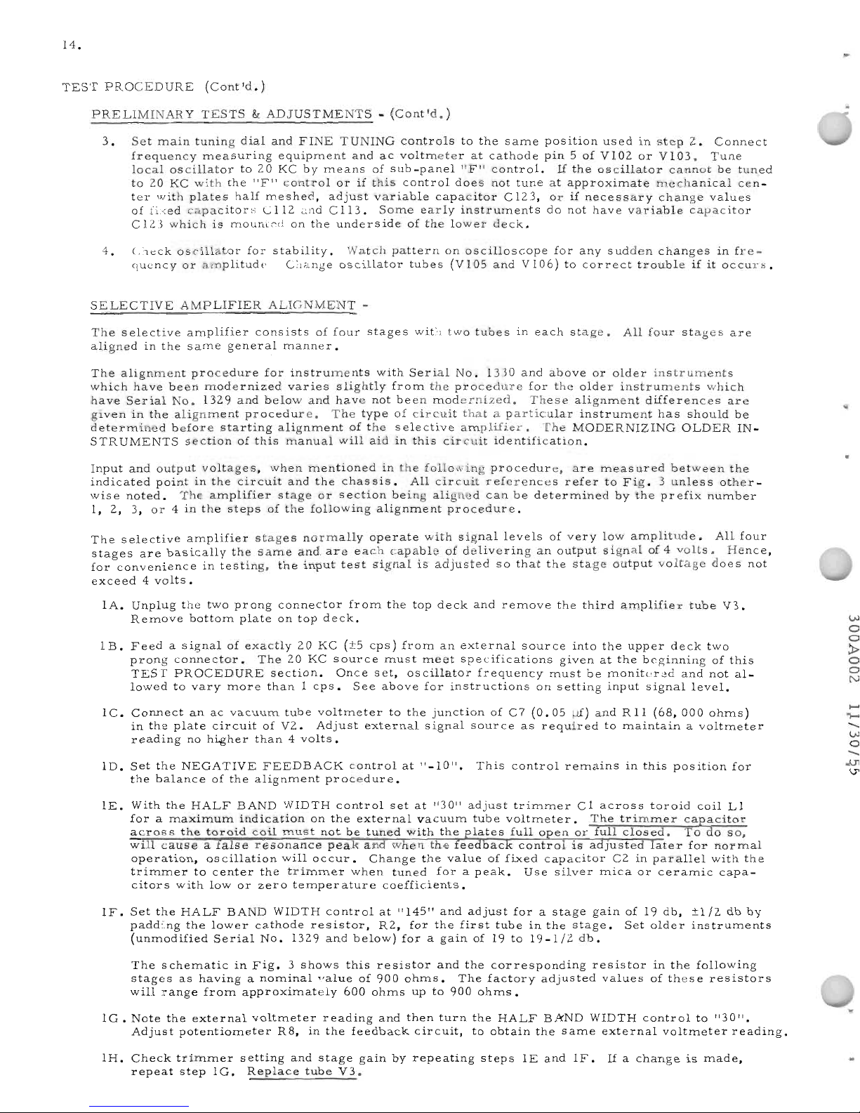
14.
TEST
PROCEDURE
(Cont'd.)
PRELIMINARY
TESTS&ADJUSTMENTS
-
(Cont'd.)
3.
Set
main
tuning
dial
and
FINE
TUNING
controls
to
the
same
position
used
in
step
2.
Connect
frequency
measuring
equipment
and
ac
voltmeter
at
cathode
pin5of
Vl02
or
VI03.
Tune
local
oscillator
to20KC
by
means
of
sub-panel
"F"
control.
If
the
oscillator
cannot
be
tun_ed
to
20
KC
with
the
"F"
control
orifthis
control
does
not
tune
at
approximate
mechanical
cen-
ter
with
plates
half
meshed,
adjust
variable
capacitor
C
123,
orifnecessary
change
values
of
fixed
capacitors
Cl12
and
Cl13.
Some
early
instruments
do
not
have
variable
capacitor
C123
which
is
mounted
on
the
underside
of
the
lower
deck.
4.
Check
oscillator
for
stability.
Watch
pattern
on
oscilloscope
for
any
sudden
changes
in
fre-
quency
or
amplitude.
Change
oscillator
tubes
(Vl05
and
Vl06)
to
correct
trouble
ifitoccurs.
SELECTIVE
AMPLIFIER
ALIGNMENT
-
The
selective
amplifier
consists
of
four
stages
with
two
tubes
in
each
stage.
All
four
stages
are
aligned
in
the
same
general
manner.
The
alignment
procedure
for
instruments
with
Serial
No.
1330
and
above
or
older
instruments
which
have
been
modernized
varies
slightly
from
the
procedure
for
the
older
instruments
which
have
Serial
No.
1329
and
below
and
have
not
been
modernized.
These
alignment
differences
are
given
in
the
alignment
procedure.
The
type
of
circuit
thataparticular
instrument
has
should
be
determined
before
starting
alignment
of
the
selective
amplifier.
The
MODERNIZING
OLDER
IN-
STRUMENTS
section
of
this
manual
will
aidinthis
circuit
identification.
Input
and
output
voltages,
when
mentioned
in
the
following
procedure,
are
measured
between
the
indicated
pointinthe
circuit
and
the
chassis.
All
circuit
references
refer
to
Fig.3unless
other-
wise
noted.
The
amplifier
stage
or
section
being
aligned
can
be
determined
by
theprefix
number
I,
2,
3,
or4in
the
steps
of
the
following
alignment
procedure.
The
selective
amplifier
stages
normally
operate
with
signal
levels
of
very
low
amplitude.
All
four
stages
are
basically
the
same
and
are
each
capable
of
delivering
an
output
signal
of4volts.
Hence,
for
convenience
in
testing,
the
input
test
signal
is
adjusted
so
that
the
stage
output
voltage
does
not
exceed4volts.
lAo
Unplug
the
two
prong
connector
from
the
top
deck
and
remove
the
third
amplifier
tube
V3.
Remove
bottom
plate
on
top
deck.
lB.
Feedasignal
of
exactly
20
KC
(±5
cps)
from
an
external
source
into
the
upper
deck
two
prong
connector.
The
20
KC
source
must
meet
specifications
givenatthe
beginning
of
this
TEST
PROCEDURE
section.
Once
set,
oscillator
frequency
must
be
monitored
and
not
al-
lowed
to
vary
more
than1cps.
See
above
for
instructions
on
setting
input
signal
level.
lC.
Connect
anacvacuum
tube
voltmeter
to
the
junction
of
C7
(0.05
1Ji)
and
Rll
(68,000
ohms)
in
the
plate
circuit
of
V2.
Adjust
external
signal
source
as
required
to
maintain
a
voltmeter
reading
no
higher
than4volts.
lD.
Set
the
NEGATIVE
FEEDBACK
control
at
"-10".
This
control
remains
in
this
position
for
the
balance
of
the
alignment
procedure.
IE.
With
the
HALF
BAND
WIDTH
control
setat"30"
adjust
trimmer
Cl
across
toroid
coil
Ll
foramaximum
indication
on
the
external
vacuum
tube
voltmeter.
The
trimmer
capacitor
across
the
toroid
coil
must
not
be
tuned
with
the
lates
full0enorfull
closed.
To
do
so,
will
cause
a
alse
resonance
peak
an
when
the
ee
ac
control
isaJuste
ater
for
normal
operation,
oscillation
will
occur.
Change
the
value
of
fixed
capacitor
C2inparallel
with
the
trimmer
to
center
the
trimmer
when
tuned
forapeak.
Use
silver
mica
or
ceramic
capa-
citors
with
low
or
zero
temperature
coefficients.
IF.
Set
the
HALF
BAND
WIDTH
control
at
"145"
and
adjust
forastage
gain
of19db,
±1/2
db
by
padding
the
lower
cathode
resistor,
R2,
for
the
first
tube
in
the
stage.
Set
older
instruments
(unmodified
Serial
No.
1329
and
below)
foragain
of19to
19-1/2
db.
The
schematic
in
Fig.
3
shows
this
resistor
and
the
corresponding
resistor
in
the
following
stages
as
havinganominal
value
of
900
ohms.
The
factory
adjusted
values
of
these
resistors
will
range
from
approximately
600
ohms
upto900
ohms.
lG.
Note
the
external
voltmeter
reading
and
then
turn
the
HALF
BAND
WIDTH
control
to
"30".
Adjust
potentiometer
R8,
in
the
feedback
circuit,
to
obtain
the
same
external
voltmeter
reading.
lH.
Check
trimmer
setting
and
stage
gain
by
repeating
steps
IE
and
IF.
Ifachange
is
made,
repeat
step
lG.
Replace
tube
V3.
VJ
o
o
~
o
o
N
......
.......
-
VJ
o
-
JJt
U1
Page 24

N
o
o
~
o
o
l""'l
15.
TEST
PROCEDURE
(Cont'd.)
SELECTIVE
AMPLIFIER
ALIGNMENT
-
(Cont'd.)
2A.
Remove
amplifier
tubes
V2
and
V5.
Disconnect
voltmeter
and
connect
output
from
external
20
KC
source
to
this
same
point
(junction
of
C7
and
Rll)
in
plate
circuit
of
V2.
Reconnect
voltmeter
to
junction
of
C16
(0.05
fli)
and
R29
(68,000
ohms)
in
V4
plate
circuit.
2B.
Repeat
step
IE
except
adjust
trimmer
C9
across
toroid
coil
L2.
Change
the
valueoffixed
capacitor
C 10ifnecessary
to
center
C9
tuning
range.
2C.
Repeat
step
IF
except
adjust
the
valueofcathode
resistor
R20.
Set
older
instruments
(un-
modified
Serial
No.
1329
and
below)
foragainof17-1/2
to18db
instead
of19db,
±1/2
db.
2D.
Repeat
step
IG
except
adjust
potentiometer
R27.
2E.
Check
trimmer
setting
and
stage
gain
by
repeating
steps
2B
and
2C.
1£
a
change
is
made,
repeat
step
2D.
Replace
tubes
V2
and
V5.
3A.
Remove
amplifier
tubes
V4
ana.
V7.
Disconnect
voltmeter
and
connect
output
from
external
20
KC
source
to
this
same
point
(junction
of
Cl6
arid
R29)inthe
plate
circuit
of
V4.
Recon-
nect
voltmeter
to
junction
of
C24
(0.05
fli)
and
R45
(68,000
ohms)
in
V6
plate
circuit.
3B.
Repeat
step
IE
except
adjust
trimmer
C17acrosstoroid
coil
L3.
Change
the
valueoffixed
capacitor
Cl8ifnecessary
to
center
C17
tuning
range.
3C.
Repeat
step
IF
except
adjust
the
value
of
cathode
resistor
R36.
Set
older
instruments
(un-
modified
Serial
No.
1329
and
below)
foragainof17-1/2
to
18dbinstead
of19db,
±1/2
db.
3D.
Repeat
step
IG
except
adjust
potentiometer
R43.
3E.
Check
trimmer
setting
and
stage
gain
by
repeating
steps
3B
and
3C.
1£
a
change
is
made,
repeat
step
3D.
Replace
tubes
V4
and
V7.
4A.
Remove
amplifier
tube
V6.
Disconnect
voltmeter
and
connect
output
from
external
20
KC
source
to
this
same
point
(junction
of
C24
and
R45)inthe
plate
circuit
of
V6.
Reconnect
voltmeter
to
junction
of
C32
(0.05
fli)
and
R60
(68,000
ohms)
in
V8
plate
circuit.
4B.
Repeat
step
IE
except
adjust
trimmer
C25
across
toroid
coil
L4.
Change
the
value
of
fixed
capacitor
C26
if
necessary
to
center
Cl7
tuning
range.
4C.
Repeat
step
IF
except
adjust
the
value
of
cathode
resistor
R52.
Set
older
instruments
(un-
modified
Serial
No.
1329
and
below)
foragain
of19to
19-1/2
db
instead
of19db,
±1/2
db.
4D.
Repeat
step
lG
except
adjust
potentiometer
R58.
4E.
Check
trimmer
setting
and
stage
gain
by
repeating
steps
4B
and
4C.
1£
a
change
is
made,
repeat
step
4D.
Replace
tube
V6.
5.
Replace
bottom
plate
on
top
deck
and
reconnect
plugs
for
two
cables
connecting
top
and
lower
decks.
Turn
instrument
upr
ight.
6.
Balance
the
modulator
as
previously
explained
under
CALIBRATION
PROCEDURE.
Adjust
the
"V"
control
forareading
of5volts
on
the
VOLTS
calibration
meter.
Flip
switch
"S"
to
the
right.
7.
Set
HALF
BAND
WIDTH
control
to
"145",
tune
in
60
cps
and
settoa
reference
point
on
the
MILLIVOLTS
meter
with
the
"G"
control.
8.
Turn
HALF
BAND
WIDTH
control
to
"3D"
and
retune
foramaximum
reading
with
the
FINE
TUNING
control.
9.
Adjust
the
NEGATIVE
FEEDBACK
control
to
obtain
the
same
reference
reading
on
the
MILLI-
VOLTS
meter.
1£
the
NEGATIVE
FEEDBACK
control
is
between
"-15"
and
"+5",
the
selec-
tive
amplifier
is
correctly
aligned.
Repeat
alignment
procedure
until
this
test
can
be
passed.
10.
Place
instrument
in
its
cabinet
and
allow
to
operate
for
several
hours
before
proceding
with
the
HEAT
RUN
CHECK
that
follows.
1£
new
coils
have
been
installed,
instrument
should
be
operated
continually
for
at
least
24
hour
s.
Upto3or4
days
heat
runisre
commended.
Page 25

16.
TESTPR
OCED
URE
(Cont
'd.
)
HEA
T RUNCHECK
-
1.
Allow
instrument
to
operate
for
several
hours.
Check
the
position
of
the
NEGATIVE
FEED-
BACK
control
as
directed
in
steps
6, 7,
8,
and9of
the
SELECTIVE
AMPLIFIER
ALIGNMENT
procedure
and
record
the
control
setting.
2.
Turn
instrument
off
and
letifcool
over
night.
Repeat
last
step
when
instrument
has
been
on
forafew
minutes
and
again
record
the
NEGATIVE
FEEDBACK
control
setting.
3.
Repeat
steps1and2until
the
instrument
is
stabilized
as
indicated
by
the
NEGATIVE
FEED-
BACK
control
not
requiring
excessive
adjustment
between
"hot"
and
"cold"
operating
temper-
atures.
The
adjustment
required
may
drift
outside
the
limits
of
this
control.
In
this
case,
the
ampli-
fier
should
again
be
aligned
and
the
unit
put
on
heat
run.
This
realignment
may
be
required
a
third
time.
If
the
instrument
will
not
stabilize,
it
may
be
necessary
to
replace
one
or
more
of
the
toroid
coils.
The
defective
coil
can,
in
most
cases,
be
located
during
realignment
of
the
selective
amplifier.
Change
the
coil
in
the
amplifier
section
that
requires
excessive
retuning
and
re-
adjustment
of
the
internal
feedback
potentiometer
(R8,
R27, R43,
or
R58).
Once
the
instrument
is
stabilized
it
is
ready
for
the
final
test.
FINAL
TEST
-
1.
Check
regulated
output
voltage
in
power
supply
as
directed
in
the
PRELIMINAR
Y
TESTS
&:
ADJUSTMENTS
section
of
this
manual.
2.
Check
oscillator
voltage
as
directed
in
PRELIMINARY
TESTS
&:
ADJUSTMENTS.
3.
Check
oscillator
stability
and
response
to
line
voltage
change
as
follows:
A.
Applya400
cps,
1/2
volt
signal
to
input
terminals
and
tune
instrument
to
same
frequency
with
HALF
BAND
WIDTH
control
setat"145".
B.
Adjust
MILLIVOLTS
meter
to
full
scale
with
control
"G".
C.
Turn
HALF
BAND
vvIDTH
control
to
"30"
and
repeak
signal
with
FINE
TUNING
control.
Adjust
NEGATIVE
FEEDBACK
control
forafull
scale
MILLIVOLTS
meter
reading.
D.
Turn
the
line
voltage
down
to
105
volts
with
the
variable
transformer.
The
meter
read-
ing
normally
drops
to
half
scale.
When
the
meter
has
stopped
drifting,
retune
with
the
FINE
TUNING
control.
The
meter
should
read
within
15%offull
scale.
A
change
of
greater
than
15%isusually
caused
byaweak
tube.
Tubes
VI05
and
VI06
in
the
local
oscillator,
as
well
as
tubes
V9
and
VIOinthe
meter
circuit
should
be
checked
fir
st.
4.
Repeat
the
SELECTIVE
AMPLIFIER
ALIGNMENT
procedure
asafinal
selective
amplifier
alignment.
5.
With
no
input
to
instrument,
set
frequency
dial
to
midscale
and
the
SET
TO
100
dial
to
zero.
Set
the
mechanical
zero
on
the
MILLIVOLTS
meter
to
zero.
The
instrument
must
beatnor-
mal
operating
temperature
when
this
adjustment
is
made.
6.
Balance
the
modulator
as
explained
in
steps1through
11ofCALIBRA
TION
PROCEDURE.
Check
control
"C"
butterfly
capacitor,
CI07,
to
see
thatitis
meshed
equally
on
both
sides.
An
unbalanced
setting
of
this
capacitor
is
an
indication
that
modulator
tubes
Vl02
or
VI03
are
unbalanced,
modulation
transformer
(T101)isdefective,
or
there
are
other
defective
parts
in
the
modulator
circuit.
Refer
to
the
TROUBLE
SHOOTING
section
of
this
manual.
7.
Check
for
carrier
leakage.
Balance
modulator
with
HALF
BAND
WIDTH
control
at
"145
",
METER
SENSITIVITY
control
at
"500",
and
frequency
dial
at
"0".
Turn
METER
SENSITIV-
1Tyto"25",
rebalance
modulator,
turn
control
back
to
"500",
and
note
MILLIVOLTS
meter
reading.
Carrier
leakage
caused
by
the
20
KC
signal
from
the
local
oscillator
feeding
through
the
power
supply
into
the
top
deck
will
result
inahigher
MILLIVOLTS
meter
reading.
Cor-
rective
steps
are
given
in
the
TROUBLE
SHOOTING
section
of
this
manual.
•
..
....
....
-.
l>'
o
.......
U1
U1
..
Page 26

17.
TEST
PROCEDURE
(Cont1d.)
FINAL
TEST-(Cont'd.)
8.
Check
for
hum
as
follows:
A.
Balance
the
modulator.
B.
Set
METER
SENSITIVITY
control
to
"500"
and
HALF
BAND
WIDTH
control
to
"145".
C.
Set
the
sub-panel
meter
to5volts
with
control
"V".
Flip
lever
switch
"S"tothe
right.
D.
Tune
instrument
at60cps
foramaximum
MILLIVOLTS
meter
reading.
Adjust
control
"G"toobtainafull
scale
MILLIVOLTS
meter
indication.
E.
Turn
HALF
BAND
WIDTH
control
to
"30"
and
retune
instrument
foramaximum
MILLI-
VOLTS
meter
reading.
Adjust
NEGATIVE
FEEDBACK
control
to
obtainafull
scale
MILLIVOLTS
meter
reading.
F.
Flip
lever
switch
"5"tothe
left
(vertical
position)
and
turn
the
METER
SENSITIVITY
switch
to
"1".
G.
Balance
hum
potentiometer
(R159)inlower
deck
foraminimum
MILLIVOLTS
meter
reading.
The
reading
obtained
should
notbemore
than
0.08
millivolts.
H.
Retune
instrument
to
120
cps
and
then
180
cps.
The
MILLIVOLTS
meter
reading
again
should
notbemore
than
0.08
millivolts.
Refer
to
the
TROUBLE
SHOOTING
notes
on
hum
removal.
9.
Check
resonance
curves
as
follows:
A.
Check
resonance
curve
fora60
cps
"hump".
Set
HALF
BAND
WIDTH
control
to
"30";
METER
SENSITIVITY
at
"500";
METER
MULTIPLIER
at
".5";
SET
TO
100at"100";
and
connecta400
cps,
1/2
volt,
external
source
to
the
input
terminals.
Tune
instru-
ment
to
400
cps
and
adjust
control
"G"
forafull
scale
MILLIVOLTS
meter
deflection.
Gradually
shift
the
external
oscillator
frequency
and
switch
the
METER
SENSITIVITY
control
counterclockwise
to
maintain
a
MILLIVOLTS
meter
reading.
The
meter
indication
should
drop
gradually.
When
the
oscillator
is
60
cps
away
from
400
cps,
the
gradual
drop
may
showahesitation
orasmall
rise
whichisan
indication
ofa60
cps
"hump"
in
the
resonance
curve.
The
external
oscillator
must
be
tuned
on
both
sides
of
400
cps
for
this
test.
Refer
to
TROUBLE
SHOOTING
section
of
this
manual
for
methods
of
eliminating
this
"hump".
Plot
the
resonance
curve
on
the
broad
sample
curve
given
in
Fig.
8.
The
plotted
curve
should
fall
within
the
two
outside
lines
of
sample
curve.
Set
instrument
controls
and
connect
external
signal
source
asinstep
9A
except
set
HALF
BAND
WIDTH
control
at
"145".
Peak
instrument
forafull
scale
MILLIVOLTS
meter
reading
at
400
cps.
Set
external
oscillator
to
420,
460,
520,
545,
and
700
cps.
Record
millivolt
reading
obtained
at
each
frequency.
Repeat
this
same
process
after
recording
the
readings
obtained
by
tuning
the
external
oscillator
to
380,
340,
280, 255,
and
100
cps.
If
the
plotted
curves
fall
outside
the
sample
curve
limits,
it
will
be
necessary
to
change
the
value
of
anyone
or
all
four
resistors
R18,
R34,R74,
andR77
across
the
toroid
coils.
Increasing
a
resistor
value
will
sharpen
the
resonance
curves
in
both
broad
("145")
and
sharp("30")
HALF
BAND
WIDTH
control
positions.
Adjustment
of
the
broad
curve
must
be
completed
before
attempting
adjustment
of
the
sharp
tuning
curve.
B.
1.t'l
I."')
-
0
ri'f
-
.
..,.
-
N
0
0
<:
0
0
C.
<""\
The
selective
amplifier
must
be
realigned
after
changing
anyofthese
four
resistors.
D.
Set
HALF
BAND
WIDTH
control
to
"30"
(sharp)
and
plot
resonance
curve,
using
the
pro-
cedure
given
in
step
9B
except
take
readings
at
10,
20,
30,
40,
50,
60,
and
70
cps
above
and
below
400
cps.
Particular
attention
should
be
giventothe
frequencies
of
340
and
460
cpstobe
sure
thata"hump"
does
not
appear
as
explained
in
step
9A.
Page 27

18.
..
TEST
PROCEDURE
(Cont'd.)
FINAL
TEST-(Cont'd.)
9D.
(Cont'd.)
If
the
plotted
curves
fall
outside
the
sample
curve
limits,
it
will
be
necessary
to
change
the
value
of
either
or
both
resistors
R75andR76inthe
feedback
circuits
of
the
two
center
stages.
Decreasing
the
value
of
these
resistors
will
sharpen
the
resonance
curve.
The
selective
amplifier
must
be
realigned
after
changing
either
resistor
values.
Changing
either
or
bothofthese
resistor
values
will
not
affect
the
broad
tuning
curve.
If
the
two
sides
of
the
resonance
curve
are
not
symmetrical,
repeat
this
step
after
very
carefully
peaking
the
instrument
to
400
cps
with
the
MILLIVOLTS
meter.
Refer
to
the
TROUBLE
SHOOTING
section
of
this
manual
if
the
resonance
curve
is
still
not
symmet-
rical.
10.
Check
harmonic
distortion
in
the
300Aasfollows:
A.
Balance
the
modulator,
set
HALF
BAND
WIDTH
control
to
"145",
and
switch
METER
SENSITIVITY
to
"500".
Connect
an
external
signal
source
with
pure
wave
filter
to
input
terminals
and
adjust
to
deliver
a
0.5
volt
signal
at
approximately
1600
cps.
The
external
signal
source
may
have
as
high
as
1.00/0
distortion
provided
a
pure
wave
filter
is
used
between
this
source
and
the
300A
input.
Refer
to
INSTR
UMENTS
REQUIRED
FOR
TEST
PROCEDURE
at
the
beginning
of
this
TEST
PROCEDURE
section.
B.
Peak
the
300Atothe
input
signal
and
adjust
the
MILLIVOLTS
meter
to
full
scale
with
control
"G".
Retune
instrument
to
the
second
harmonic
(32.00
cps)
and
set
METER
SENSITIVITY
switch
to
"1".
C.
Adjust
potentiometer
Rl17
in
the
grid
circuit
of
balanced
modulator
tubes
(Vl02
and
Vl03)
foraminimum
MILLIVOLTS
meter
reading.
Rebalance
the
modulator
and
again
adjust
Rl17
foraminimum
reading.
The
remaining
MILLIVOLTS
meter
reading
should
not
be
more
than
0.2
millivolts.
This
reading
is
an
indication
of
input
signal
distortion
by
the
300A.
Retune
the
300A
to-
the
third
harmonic
(4800
cps)
and
note
the
MILLIVOLTS
meter
read-
ing.
This
reading
should
again
not
be
more
than
0.2
millivolts.
D.
Repeat
steps
lOA
and
lOB
with
external
signal
source
tuned
to
approximately
6300
cps
and
check
second
harmonic
(12,600
cps)
only.
The
MILLIVOLTS
meter
readi~g
obtained
should
notbegreater
than
0.2
millivolts.
11.
Check
HALF
BAND
WIDTH
variable
selectivity
control
as
follows:
A.
Connecta400
cps,
0.5
volt,
sine
wave
signal
to
the
300A
input
terminals.
Tune
instru-
ment
foramaximum
reading
with
HALF
BAND
WIDTH
control
at
"145".
Set
MILLI-
VOLTS
meter
toareference
point
of
".8"
with
control
"G".
The
METER
SENSITIVITY
switch
should
be
on
"500".
B.
Set
HALF
BAND
WIDTH
control
to
"30"
and
repeak
the
instrument
with
the
FINE
TUNING
control.
Adjust
NEGATIVE
FEEDBACK
controlfor
same"
.8"
MILLIVOLTS
meter
ref-
erence
reading.
C.
Turn
the
HALF
BAND
WIDTH
controlfor
a
maximum
reading
on
the
MILLIVOLTS
meter
and
repeakthesignalwith
the
FINE
TUNING
control.
The
resultant
MILLIVOLTS
meter
read-
ing
should
benogr
eater
than"1•0".Ifthe
readingifoff
scale,
refer
to
the
TR
OUB
LE
SHOOTING
section
of
this
manual.
12.
Check
MILLIVOLTS
meter
tracking
as
follows:
A.
Check
mechanical
zero
as
described
in
FINAL
TEST
step
5.
B.
Set
the
300Atoread
voltages
accurately
as
explained
in
steps
26A
and
26B
of
PROCED-
URE
FOR
CALIBRATION.
Introduce
a
400
cps
signai
and
check
MILLIVOLTS
meter
tracking
against
a
meter
with
known
calibration
accuracy.
The
300A
voltmeter
readings
should
be
within
±20/0ofthe
full
scale
reading.
13.
Check
instrument
sensitivity
as
follows:
A.
Set
METER
SENSITIVITY
at
"500",
control
"G"
full
clockwise,
SET
TO
100
control
full
clockwise,
METER
MULTIPLIER
at
".5",
and
HALF
BAND
WIDTH
control
at
"145".
..
Page 28

TEST
PROCEDURE
(Cont'd.)
FINAL
TEST-(Cont'd.)
13.
(Cont'd.)
19.
B.
Connect
400
cps
from
an
external
oscillator
to
input
terminals
and
tune
300A
foramaxi-
mum
MILLIVOLTS
meter
reading.
Adjust
external
os
cillator
forafull
scale
MILLI-
VOLTS
meter
reading.
The
input
signal,
as
measured
at
the
input
terminals
byanac-
curate
external
voltmeter,
will
normally
be
0.25
volt
or
less.
If
external
signal
is
0.5
volt
or
less,
sensitivity
is
satisfactory.
See
TROUBLE
SHOOTING
section
if
input
volt-
ageistoo
high.
14.
Check
main
tuning
dial
frequency
calibration
as
follows:
A.
Set
frequency
dial
at
"0"
and
FINE
TUNING
control
with
knob
indicator
straight
up.
Tune
control
"F"
foramaximum
MILLIVOLTS
meter
reading
which
will
indicate
that
the
in-
ternal
oscillator
frequency
is
20
KC.
Rotor
plates
of
"F"
control
trimmer
should
be
approximately
half
meshed
with
stator
plates
when
tunedto20
KC.
If
they
are
not,
orifinternal
oscillator
cannot
be
tuned
to
20
KC
with
control
"F",
it
will
be
necessary
to
adjust
variable
capacitor
Cl23
(See
Fig.
4).
If
necessary,
the
values
of
fixed
capacitors
Cll2
and
Cll3
may
be
adjusted.
In
older
instruments
having
fixed
capacitors
Cl12
and
Cll3
only,
adjustment
can
be
made
only
by
changing
these
capacitor
values.
When
oscillator
isonfrequency
in
approximate
center
of
tuning
range
for
control
"F",
balance
the
modulator.
Do
not
change
setting
of
control
"F"
or
the
FINE
TUNING
con-
trol
for
remaining
portion
of
this
step.
Check
frequency
dial
calibration
with
an
external
oscillator
andafrequency
standard
or
other
frequency
measuring
device
connected
to
the
300A
input
terminals.
Adjust
main
tuning
dial
foramaximum
MILLIVOLTS
meter
indication
and
note
the
dial
reading.
Re-
peat
this
processacross
the
instrument
frequency
range.
Frequency
dial
calibration
should
be
within
±3%atfrequencies
of
100
cps
or
higher
and
±5%atfrequencies
below
100
cps.
To
correct
poor
frequency
dial
tracking,
pad
Rl38
and
Rl39
precision
resistors
and
re-
adjust
variable
capacitor
Cl23
or
change
fixed
capacitors
CIl2
and
Cll3
to
bring
oscil-
lator
on
frequency.
Series
or
parallel
resistor
pads
may
be
used
depending
upon
the
tracking
error
to
be
corrected.
Increasing
either
or
both
these
resistor
values
will
de-
creaseos
cillator
frequency.
B.
Check
andifnecessary
adjust
oscillator
injection
voltage
at
VI02
and
Vl03
cathodes
as
directed
in
step2of
PRELIMINARY
TESTS&ADJUSTMENTS.
Turn
frequency
dial
from
toptobottom
while
measuring
cathode
injection
voltage
of
Vl02
and
VI03.
Ii
injection
voltage
is
not
constant,
reset
variable
capacitor
C123
and
bring
oscillator
on
frequency
with
control
"F".
If
range
ofC123isnot
wide
enough
or
C
123isnotina
particular
instrument,
change
capacity
ratio
of
fixed
capacitors
C
112
and
Cl13.
Increase
the
capacity
of
one
while
decreasing
the
capacity
of
the
other
an
equal
amount.
The
capacity
change
required
must
be
experimentally
determined.
Oscillator
injection
voltage
may
be
adjusted
foraslight
rise
at
topofdial
to
compensate
instrument
frequency
respons
e.
15.
Check
frequency
response
as
follows:
A.
Set
HALF
BAND
WIDTH
control
to
"145",
connect
external
voltrr.eter
and
audio
signal
generator
to
300A
input
terminals,
and
adjust
for
an
input
of
0.5
voltat100
cps.
Tune
forapeak
MILLIVOLTS
meter
reading
and
adjust
control
"G"
forareference
reading
of
0.9
on
the0to1.0
MILLIVOLTS
meter
scale
with
METER
SENSITIVITY
setto"500".
B.
Tune
generator
and
300Ato1
KC,
10
KC,
and
16
KC
while
maintaining
a
contstant
input
voltage.
External
voltmeter
must
be
flat
over
this
frequency
range.
The
MILLIVOLTS
meter
readings
should
not
vary
from
the
reference
point
by
more
than
±2%offull
scale.
Correct
a
slight
error
by
adjusting
the
internal
oscillator
frequency
response
as
explained
in
step
14B.
To
correct
a
large
error,
see
the
TROUBLE
SHOOTING
section.
Page 29

20.
TEST
PROCEDURE
(Cont'd.)
FINAL
TEST-(Cont'd.)
16.
Check
voltage
calibration
as
follows:
A.
Balance
the
modulator,
set
HALF
BAND
WIDTH
control
to
"145",
set
METER
SENSI-
TIVITY
to
"500",
turn
SET
TO
100
control
full
clockwise,
and
set
METER
MULTIPLIER
control
to
" •
5".
B.
Intro:luce
a
measured
400
cps
voltage
of
exactly
0.5
volt
into
the
300A
input
terminals.
Tune
forapeak
and
set
MILLIVOLTS
meter
to
full
scale
with
"G"
control.
C.
Turn
control
"V"
full
counterclockwise
and
adjust
the
mechanical
zero
of
the
VOLTS
meter.
D.
Flip
switch
"S"tothe
right
and
adjust
control
"V"
forareading
of5volts
on
the
VOLTS
meter.
E.
Tune
instrument
forapeak
MILLIVOLTS
meter
reading
at
60
cps.
00
NOT
CHANGE
THE
"G"
CONTROL
SETTING.
F.
The
MILLIVOLTS
meter
reading
should
be
full
scale.
If
not,
adjust
the
60
cps
signal
forafull
scale
reading
by
padding
either
RI06
orR107inthe
voltage
divider.
Maintain
a
VOLTS
meter
reading
of5volts
with
control
"V"
and
pad
RI06
or
RI07
to
obtain
a
full
scale
MILLIVOLTS
meter
reading.
G.
Recheck
forafull
scale
reading
at
400
cps
asinstepBexcept
do
not
change
the
"G"
control
setting.
H.
Repeat
stepsBthrough
G
untilafull
scale
reading
is
obtained
for
steps
F
andGby
set-
ting
control
"V"
for5volts
and
tuning
forapeak
MILLIVOLTS
meter
reading.
17.
Check
the
METER
SENSITIVITY
control
as
follows:
A.
Set
METER
MULTIPLIER
to
".5",
SET
TO
100
control
full
clockwise,
HALF
BAND
WIDTH
control
to
"145",
and
METER
SENSITIVITY
control
to
"500".
B.
Connect
output
terminals
ofaprecision
attenuator
to
300A
input
terminals.
Use
the
cor-
rect
value
of
attenuator
load
as
specified
by
the
attenuator
manufacturer.
This
load
may
be
connected
across
the
300A
input
terminals.
C.
Couplea400
cps
source
to
the
attenuator
input
and
adjust
both
attenuator
and
source
to
provide
a
0.5
volt
(500
millivolts)
input
signal
to
the
300A.
The
resulting
signal
level
at
the
attenuator
input
must
be
maintained
constant
for
the
balance
of
this
procedure.
D.
Peak
the
300A
foramaximum
MILLIVOLTS
meter
indication
and
set
control
"G"
for
a
full
scale
reading
of
500
millivolts.
DO
NOT
CHANGE
THE
SETTING
OF
CONTROL
"G"
FOR
THE
BALANCE
OF
THIS
TEST.
..
E.
Maintain
a
constant
attenuator
input
level.
Refer
to
the
table
on
the
right.
Adjust
the
attenuator
to
introduce
amount
of
attenua-
tion
given
in
column
one,
set
the
METER
SENSITIVITY
control
to
the
position
given
in
column
two,
and
adjust
the
FINE
TUNING
control
foramaximum
MILLIVOLTS
meter
indication.
In
each
case,
the
resulting
MILLIVOLTS
meter
reading
should
be
with-
in
±2%offull
scale.
This
check
is
accurate
only
when
the
input
level
is
maintained
constant
andaproperly
terminated
precision
attenuator
is
used.
Attenuation
METER
SENSITIVITY
in
db
Control
Setting
0
·
·
·
·
· · ·
500
6
···
·
···
250
14
· · · ···
·
100
20
·
·
·
· · ·
50
26
··· · · · ·
25
34
··· · · · ·
10
40
· · ·
·
· · ·
5
46
·
· ·
· · · ·
2.5
54
· · · ·
·
·
·
1
The
external
audio
oscillator,
ac
voltmeter,
attenuator,
and
300A
should
be
grounded
through
the
input
test
cable
only.
One
side
of
the
audio
oscillator
output
cable
should
be
grounded
to
oscillator
chassis
at
the
output
terminals.
A
ground
loop
may
cause
erroneous
readings
when
measuring
low
ac
voltages.
Page 30

N
o
o
«
o
o
M
21.
TEST
PROCEDURE
(Cont'd.)
FINAL
TEST
-
(Cont'd.)
18.
Check
the
METER
MULTIPLIER
control
as
follows:
A.
Set
METER
MULTIPLIER
to
".5",
SET
TO
100
control
full
clockwise,
HALF
BAND
WIDTH
control
to
"145",
and
METER
SENSITIVITY
control
to
"500".
B.
Apply
exactly
0.5
volt
(500
millivolts)
at
approximately
400
cpstothe
300A
input
ter-
minals.
Peak
the
300A
foramaximum
MILLIVOLTS
meter
indication
and
set
control
"G"
forafull
scale
reading
of
500
millivolts.
DO
NOT
CHANGE
THE
SETTING
OF
CONTROL
"G"
FOR
THE
BALANCE
OF
THIS
TEST.
C.
Set
the
METER
MULTIPLIER
and
METER
SENSITIVITY
controls
to
the
positions
given
in
the
following
chart
and
note
the
MILLIVOLTS
meter
reading
which
should
beasin-
dicated
in
this
same
chart.
Maintainaconstant
input
signal
level.
METER
MULTIPLIER
METER
SENSITIVITY
MILLIVOLTS
Meter
Control
Setting
Control
Setting
Reading
• 5
500
Set
level
to
full
scale
•
5
50
Full
Scale,
±l%.
50
5
Full
Scale,
±l%.
500
1
Half
Scale,
±2%.
19.
In
some
older
instruments,
random
noise
may
causeaslight
erratic
movement
of
the
MILLI-
VOLTS
meter
pointer.
Installation
of
resistor
R73(220
ohms,
±10%,1watt)
and
capacitor
C36
(500~,
15
vdcw,
electrolytic)
in
the
voltmeter
circuit
will
eliminate
this
erratic
move-
ment.
This
network
may
be
added
on
the
top
deck
behind
the
MILLIVOLTS
meter
onatie-
point
installed
for
that
purpose.
These
components,
when
factory
installed,
are
mounted
on
the
underside
of
the
top
deck.
20.
Install
"CALIBRATION
PROCEDURE"
labels
on
the
inside
of
the
sub-panel
doorifthey
are
not
alreaay
there.
These
labels
are
available
asaset
from
the
factory
under
-hp-
Stock
No.
3A-43A.
21.
Give
the
instrument
a
complete
mechanical
inspection.
Check
for
missing
or
loose
screws,
poor
solder
connections,
and
missing
or
loose
shields.
Install
bottom
plates
and
replace
in
cabinet.
22.
The
metal
bottom
plate
was
fastened
to
the
inside
of
the
cabinet
in
some
older
instruments.
Solderaflexible
lead
from
this
platetoa
solder
lugonthe
backofthe
lower
deck.
This
is
necessary
to
reduce
lower
deck
hum
pick
up.
In
later
instruments,
this
plateisfastened
directly
to
the
chassis
bottom.
23.
Replace
ventilating
screen
over
instrument
back.
Turn
instrument
on
and
letitrun
for
a
few
hours.
Check
NEGATIVE
FEEDBACK
control
setting
from
time
to
time
during
this
time.
No
great
change
should
be
required
in
this
setting
as
explained
under
HEAT
RUN
CHECK
in
this
.same
section.
Page 31

,~
LQ
-
o
r"'l
-
-
-
N
o
o
<
o
o
r"'l
23.
CIRCUIT
MODIFICATIONS
GENERAL
-
The
circuit
modifications
that
follow
provide
greater
instrument
stability;
longer
component
life;
ease
of
adjustment,
testing,
and
repair;
and
better
manufacturing
procedures.
Electrical
perfor-
mance
specifications
of
the
Model
300A
have
not
changed
and
an
older
instrument
will
provide
the
same
results
asanew
instrument.
If
an
older
instrument
is
functioning
properly,
there
is
no
rea-
sontomake
any
circuit
modifications.
WARNING
MAJOR
MODIFICATIONS
SHOULDBEATTEMPTED
ONLY
WHEN
THE
NECESSARY
TEST
EOUIPMENT
IS
AVAILABLE
FOR
FINAL
TESTING
AND
ADJUSTMENTOFTHE
MODIFIED
INSTRUMENT.
INSTRUMENT
REOUIREMENTS
FOR
FINAL
TESTING
ARE
GIVENINTHE
TEST
PROCEDURE
SEC-
TION
OF
THIS
MANUAL.
Instruments
with
Serial
No.
1330
and
above
require
no
top
deck
modifications.
Instruments
with
Serial
No.
1610
and
above
require
no
modifications
in
either
the
toporbottom
decks.
The
top
deck
in
instruments
with
Serial
No.
1610
and
above
is
the
same
as
thatininstruments
with
Serial
No.
1330
and
above.
With
certain
exceptions
in
early
instruments
as
noted,
the
modifications
that
follow
will
convert
any
Model
300Asothat
the
top
deck
hasacircuit
equivalent
to
instruments
with
Serial
No.
1330
or
above
and
the
lower
deck
hasacircuit
equivalent
to
instruments
with
Serial
No.
1610orabove.
Components
necessary
for
making
circuit
modifications
are
available
from
Hewlett-packard.
How-
ever,
the
quantity
required
will
vary
depending
upon
the
ageofthe
particular
instrument
involved.
IMPORTANT
SCHEMATIC
NOTICE
ALL
CIRCUIT
REFERENCES
ARE
FOR
SCHEMATIC
DIAGRAMS
GIVENINFIGURES3OR4UN-
LESS
OTHERWISE
NOTED.
TOP
DECK
MODERNIZING
PROCEDURE
-
The
following
circuit
changes
will
convert
top
decks
in
all
instruments
with
Serial
No.
1329orbe-
low
into
the
circuit
giveninFig.
3.
A
complete
listofparts
for
this
modernization
follows
the
last
stepinthis
procedure.
There
are
some
instruments
in
the
field
havingacombination
of
toroid
coils
for
the
first
and
fourth
selective
amplifier
stages
and
solenoid
type
coils
for
the
second
and
third
stages.
These
solenoid
type
coils
are
wound
onaround
bobbin.
Instruments
with
this
coil
combination
usually
have
large
rectangular
shaped
coil
shields.
Such
instruments
should
be
returned
to
the
factory
as
field
mod-
ernization
is
not
practical.
1.
Remove
the
four
toroid
coil
shield
cans.
Install
one
watt,
precision,
carbon
film,
resistor
of
479,
000
ohms
forR74,
R18,
R34,
andR77inparallel
with
Ll,
L2, L3,
and
L4
respec-
tively.
Add
this
resistor
to
all
four
toroid
coils.
Any
other
resistors
found
across'acoil
must
be
removed.
Replace
coil
shields
by
pressing
them
firmly
over
base
on
chassis.
2.
In
some
older
instruments
it
will
be
necessary
to
replace
anyone
or
all
four
toroid
coils.
Drift
will
causealoss
in20KC
selective
amplifier
gain.
It
will
be
necessary
to
advance
the
NEGATIVE
FEEDBACK
control
farther
and
farther
clockwise
to
obtain
sufficient
gain
when
the
HALF
BAND
WIDTH
control
is
setto"30".
Amplifier
alignment
will
be
required
when
the
NEGATIVE
FEEDBACK
control
adjustment
limit
is
reached.
If
the
drift
reoccurs
repeatedly
after
amplifier
alignment,
coil
replacement
is
required.
Refer
to
TROUBLE
SHOOTING
section
andtoHEAT
RUN
CHECK
in
the
TEST
PROCEDURE
section
for
tests
to
determine
if
coil
replacement
is
necessary.
3.
Install
resistors
of
80,000
ohms,
±l%,1watt
(-hp-
Stock
No.
31-80K)
forR10
and
R59inthe
negative
feedback
circuits
for
VI
and
V7
respectively.
Install
resistors
of
56,000
ohms,
±l%,
1
watt
(-hp-
Stock
No.
31-56K)
for
R28
and
R44inthe
negative
feedback
circuits
for
V3
and
V5
respectively.
The
precision
resistors
available
under
the
-hp-
Stock
numbers
given
a-
bove
are
the
only
ones
recommended
for
this
replacement.
4.
Install
-hp-
Stock
No.
24-68K
resistors
(68,000
ohms,
±lO%,1watt,
composition)
for
RIl,
R29,
R45,
and
R60inthe
negative
feedback
networks
for
all
four
stages.
Page 32

2.4.
CIRCUIT
MODIFICATIONS
(Cont'd.)
TOP
DECK
MODERNIZING
PROCEDURE
-
(Cont'd.)
5.
Install
-hp-
Stock
No.
3l-2M
resistors
(2.0
megohms,
±l%,1watt,
carbon
film)
for
R9
and
R57inthe
positive
feedback
circuits
of
VI
and
V7
respectively.
Replace
R4
and
R5l
(shown
in
Fig.5as
being
in
series
with
R9
and
R57)
with
wire
jumpers.
6.
Install
-hp-
Stock
No.
3l-1.63M
resistors
(1.63
megohms,
±l%,1watt,
carbon
film)
for
R26
and
R42inthe
feedback
circuits
for
V3
and
V5
respectively.
Install
-hp-
Stock
No.
23-l50K
resistors
(150,000
ohms,
±lO%, 1/2watt,
composition)
forR75
andR76inseries
with
R26
and
R42
respectively.
These
1/2
watt
resistors
should
be
temporarily
mounted
since
their
value
will
probably
be
changed
during
alignment
of
the
selective
amplifier
system.
7.
ReplaceR1,R17,
R33,
and
R50
with
-hp-
Stock
No.
3l-830K
precision
resistors
(830,
000
ohms,
±l%,1watt,
carbon
film).
These
resistors
are
in
the
grid
circuits
of
VI,
V3,
V5,
and
V7
respectively.
8.
Replace
R3,
R2l,
R37,
and
R53
with
-hp-
Stock
No.
31-5000
precision
resistors
(5000
ohms,
±l%,1watt,
carbon
film).
These
resistors
are
in
the
cathode
circuits
of
VI,
V3,
V5,
and
V7
respectively.
9.
Replace
R2,
R20,
R36,
and
R52inthe
cathode
circuits
of
VI,
V3,
V5,
and
V7
respectively
with
-hp-
Stock
No.
31-900
precision
resistors
(900
ohms,
±l%,1watt,
carbon
film).
Shunt
each
of
these
four
resistors
with
an
-hp-
Stock
No.
24-3900
resistor.
These
shunt
resistors
(3900
ohms,
±lO%,1watt,
composition)
should
be
temporarily
installed
as
their
final
values
are
determined
during
alignment
and
adjustment
of
the
selective
amplifier
stages.
10.
Install
C37, C38, C39,
and
C40
(10
fl~,
±100/0,
500
vdcw,
mica,
-hp-
Stock
No.
14-10)
in
parallel
with
Rll,
R29, R45,
and
R60
respectively.
11.
Replacement
of
NEGATIVE
FEEDBACK
and
HALFBAND
WIDTH
four
gang
control
potentio-
meters
and
their
shielded
connecting
cables
is
recommended
for
complete
modernization.
This
is
particularly
important
in
instruments
with
shielded
cables
that
do
not
have
an
insu-
lating
outer
cover.
12.
In
instruments
with
Serial
No.
1106orbelow,
installR73
resistor
(220
ohms,
±lO%,1watt)
in
series
with
the
MILLIVOLTS
meter
movement.
Connect
C36
(500~,
15
vdcw
electrolytic)
capacitor
in
parallel
with
this
series
combination.
The
circuit
before
this
modification
is
,showninFig.
7A
and
afterwards
in
Figs'.3and
7B.
This
network
is
mounted
on
the
top
deck
behind
the
MILLIVOLTS
meter
onatiepoint
installed
for
this
purpose.
The
addition
of
this
network
minimizes
meter
pointer
unsteadines
s
due
to
random
noise.
These
components
when
factory
installed,
are
mounted
on
the
underside
of
the
top
deck.
PARTSREQUIRED
FOR
COMPLETE
MODERNIZATION
OFATOP
DECK
-
The
exact
number
of
parts
required
will
be
dependent
upon
instrument
age.
Maximum
quantities
are
given
below.
v.
c
c
:x:.
c
c
[\,
DESCRIPTION
Resistors,
Precisionj
fixed,
leads,
±l%,1watt,
900
ohms
••
5000
ohms
56,000
ohms
80,000
ohms
479,000
ohms
830,
000
ohms
1.63
megohms.
2.0
megohms
• •
carbon
fil
m,
axial
QUANTITY
4
4
2
2
4
4
2
2
-hp-
STOCK
NO.
31-900
31-5000
3l-56K
3l-80K
3l-479K
3l-830K
3l-1.63M
3l-2M
....
....
.....
v.
c
.....
lJ
lJ
Resistorj
fixed,
composition,
150,000
ohms,
±lO%,1/2
watt
2
23-l50K
Page 33

25.
CIRCUIT
MODIFICATIONS
(Cont'd.)
PARTS
REQUIRED
FOR
COMPLETE
MODERNIZATION
OFATOP
DECK-(Contrd.)
DESCRIPTION
Resistors;
fixed,
composition,
±lO%,
220
ohms
••
3900
ohms
68,
000
ohms
• • • •
Capacitor;
fixed,
mica,
10
flfli,
±lO%,
500
vdcw
Capacitor;
fixed,
electrolytic,
tubular,
500
1Ji,
15
vdcw
••••••••
watt,
QUANTITY
1
4
4
4
-hp-
STOCK
NO.
24-220
24-3900
24-68K
14-10
18-5
NEGATIVE
FEEDBACK
and
HALF
BAND
WIDTH
control
assemblies
with
shielded
and
insulated
connecting
harness
Toroid
coil
tuned
circuit
assembly;
20
KC
BOTTOM
DECK
MODIFICATION
PROCEDURE
-
4
3A-15
3A-62
U"\
U"\
.....
o
~
........
.....
-
Modifications
that
follow
are
divided
into
separate
procedures
since
it
may
not
be
necessary
or
desirable
to
incorporate
all
modifications
unless
required.
After
some
modifications
have
been
completed,
little
or
no
instrument
adjustment
is
required
while
after
other
modifications
extensive
instrument
adjustments
are
required.
Instrument
age
will
determine
parts
requirements
foraparticular
modification.
All
possible
parts
required
are
identified
by
-hp-
stock
number
as
well
asacomplete
description.
Determine
parts
requirements
by
reading
throughamodification
while
referring
to
i.nstrument
tobechanged.
Parts
required
can
then
be
secured
from
-hp-
oralocal
source.
MODIFICATION
TO
REDUCE
CARRIER
LEAKAGE
-
When
incorporated
in
instruments
with
Serial
No.
1369orbelow,
this
modification
will
pro-
vide
reduced
carrier
leakage.
Step7of
the
FINAL
TEST
procedure
gives
the
method
of
checking
carrier
leakage.
Instruments
with
Serial
No.1370
and
above
had
this
modification
included
dur
ing
manufacture.
This
modification
can
be
incorporated
at
any
time
and
requires
no
special
instrument
adjust-
ments
following
completion.
Any
instruments
withasingle
three
section
capacitor
for
C 12
5,
C126,
and
C127
should
have
this
modification
incorporated
before
or
when
replacement
of
this
electrolytic
is
necessary.
Basically
three
mechanical
changes
are
made
in
the
instrument
wiring
when
incorporating
this
revision.
Coupling
in
the
common
electrolytic
capacitor
for
Cl25,
Cl26,
and
Cl27
is
eliminated
in
older
instruments
by
installing
separate
capacitors.
Leads
carrying
B+
are
eliminated
in
any
cabling
crossing
the
front
of
the
chassis.
Resistor
Rl54
is
moved
to
a
new
mounting
location
to
provide
better
circuit
isolation.
N
o
o
ex:
o
o
:"'l
1•
Chassis
With
a
Sin~le
3
Section
Capacitor
-
Disconnect
all
wires
(usually
five)
connecting
to
poslhve
termma
softhree
sechon
electrolytic
capacitor
for
Cl25,
C126,
and
C127.
Trace
allofthese
wires
through
the
instrument
cabling
and
disconnect
other
endofwire.
Remove
wires
completely
or
clip
them
offatpoint
of
entry
into
cabling.
Chassis
With3Separate
Capacitors
-
Potentiometer
Rl23
(control
"R")
will
have
two
wues
connected
to
ltS
center
termlnaI.
Oneofthese
wires
goes
through
the
cabling
to
screen
grid
pin6of
VI02
and
VI03
as
well
as
transformer
TIOl.
This
wire
must
re-
main
in
the
instrument
as
is.
Trace
the
other
wire
connecting
the
center
terminal
of
Rl23
to
one
endofR154.
Disconnect
both
endsofthis
second
wire
and
remove
completely
or
clip
off
ends
at
point
of
entry
into
cabling.
Locate
the
common
junction
of
power
resistors
Rl48,
Rl49
(both
10,000
ohms),
and
two
wires.
The
other
endofoneofthese
wires
connects
toatie
lug
junction
ofR144,R145,
and
Cl27
near
the
VI05
tube
socket.
The
second
wire
terminates
at
the
cathode
of
series
voltage
regulator
tube
VI09.
Page 34

26.
CIRCUIT
MODIFICATIONS
(Cont'd.)
BOTTOM
DECK
MODIFICATION
PROCEDURE
-
(Cont'd.)
MODIFICATION
TO
REDUCE
CARRIER
LEAKAGE-(Cont'd.)
1.
(Cont'd.)
..
".
If
this
second
wire
enters
step4can
be
eliminated.
ment,
disconnect
and
clip
cabling
across
rear
of
instrument,
it
need
not
be
changed
and
However,
if
this
wire
enters
cabling
across
front
of
instru-
off
both
ends
of
wire
at
point
of
entry
into
cabling.
2.
Add
or
move
capacitors
CI25,
C126,
and
Cll7
so
that
they
are
connected
electrically
as
shown
in
Fig.
4
and
as
described
below.
The
required
tubular
electrolytic
capacitor
(10
~,
450
volts)
is
available
under
-hp-
Stock
No.
18-10.
These
three
capacitor
s
have
their
negative
terminals
connected
toaconvenient
chas
sis
ground
and
their
positive
terminals
connected
as
follows:
C
125-to
tie
point
junction
ofR121,
T 10 1
transformer,
and
screen
grid
pins6for
Vl02
and
Vl03.
C
126-to
tie
point
junction
ofR136and
R 13 7inVI04plate
cir
cuit.
C127-to
tie
point
junction
of
R144
and
R145
in
Vl05
plate
circuit.
Refer
to
Fig.
11
for
approximate
mounting
positions.
It
will
be
necessary
to
add
all
three
of
these
capacitors
to
any
instrument
from
which
a
single
triple
section
electrolytic
capacitor
is
removed
as
directed
in
step
1.
3.
Remove
R154
(15,000
ohms,
±lO%,2watts,
-hp-
Stock
No.
25-l2K)
from
present
mounting
terminals
and
reconnect
as
directed
in
the
procedure
that
follows.
L
ocate
the
junction
ofR144
andR145
which
is
usually
a
terminal
on
one
endofa
dual
tie
lug
strip.
The
opposite
endofthis
tie
lug
strip
may
be
vacant
or
have
other
compo-
nents
and
wires
connected
to
it.
Any
such
connection
to
this
second
terminal
must
be
moved
to
an
electrically
equivalent
point
elsewhere
in
the
instrument.
If
this
is
not
convenient,
mountanew
tie
lug
close
enough
to
provide
a
mounting
terminal
for
one
end
ofR154
when
the
other
endisconnected
to
the
tie
lug
junction
ofR144
andR145.
Mount
R154
between
the
two
tie
lugs
just
identified.
This
connects
one
resistor
end
to
the
junction
of
R144
and
R145
and
the
other
endtoa
vacant
insulated
tie
lug.
Connect
a
wire
between
this
vacant
tie
lug
and
circuit
point
to
which
screen
grids
(pin6)of
Vl02
and
Vl03
are
connected.
4.
Connect
a
wire
between
power
supply
series
regulator
tube
(Vl09)
cathode
and
junction
of
R144,
R145,
and
R154.
This
wire
need
not
be
added
if,
in
step
I,itwas
not
neces-
sary
to
remove
a
wire
connecting
these
two
points
together.
If
in
doubt,
add
this
sec-
ond
wire
as
no
harm
can
be
done
by
doing
so.
POWER
SUPPLY
MODIFICATION
-
The
power
supply
for
all
instruments
is
fundamentally
the
same.
However,
there
have
been
minor
circuit
changes
and
different
tube
types
used
for
power
supply
circuitry
as
shown
by
Figs.
4,
6,
7C,
and
7D.
As
long
asapower
supply
is
functioning
properly
as
determined
by
tests
given
in
the
FINAL
TEST
procedure
section,
there
is
no
need
to
attempt
any
type
of
power
supply
modernization.
Replace
power
supply
tubes
with
the
same
types
found
inaninstrument.
If
the
power
supply
inaparticular
instrument
becomes
erratic
or
fails
repeatedly,
dismantle
the
power
supply
and
rewire
according
to
Fig.
4
schematic
diagram.
Install
new
parts
throughout,
change
tube
sockets
as
required,
andifnecessary
change
the
power
transformer.
The
power
transformer
change
will
beamust
when
modernizing
extremely
old
instruments
havingatype
2A3
tube
for
the
series
regulator
tube.
After
rebuilding
a
power
supply,
complete
steps1and2.of
PRELIMINAR
Y
TESTS
&
ADUST-
MENTS
and
check
harmonic
distortion
as
described
in
step
10ofFINAL
TEST
procedure.
Measure
local
oscillator
frequency
with
main
tuning
dial
at
"0"
and
FINE
TUNING
control
vertical.
The
local
oscillator
should
tune
to20KC
with
control
"F"
in
the
approximate
cen-
ter
of
its
tuning
range.
VJ
a
o
~
o
o
N
'-'
'-'
-
VJ
o
-
(]l
(]l
Page 35

•
It''l
~
o
C"'\
-
.....
.....
N
o
o
<
o
o
C"'\
27.
CIRCUIT
MODIFICATIONS
(Cont'd.)
BOTTOM
DECK
MODIFICATION
PROCEDURE
-
(Cont'd.)
OTHER
LOWER
DECK
MODIFICATIONS
-
The
following
changes
should
be
incorporated
in
instruments
only
when
required
or
applic-
able.
Replacement
of
any
frequency
determining
components
such
as
Cl12,
Cl13,
R138,
or
R139
in
steps2and3will
necessitate
a
complete
frequency
calibration
according
to
step
14
and
15ofFINAL
TEST
procedure
in
this
manual.
1.
This
modification
applies
to
instruments
with
Serial
No.
947
and
below.
Instruments
with
higher
serial
numbers
had
this
component
change
made
during
manufacture.
Replace
the3watt,
115
volt
lamp
(R140)inVI05
cathode
circuit
with
a 10
watt,
230
volt
lamp
available
under
-hp-
Stock
No.
211-29.
Complete
step2of
PRELIMINARY
TESTS
&
ADJUSTMENTS.
Resistor
R143
will
beafixed
resistor
in
instruments
requiring
this
change.
The
series
padding
resistor
value
will
be
from0to
1000
ohms.
If
this
adjust-
ment
range
is
not
adequate
foraparticular
lamp
bulb,
reject
the
bulb
and
tryadifferent
one.
2.
Local
oscillator
frequency
determining
capacitors
Cl12
and
Cll3
should
be
silver
mica
or
ceramic
type
units
with
low
or
zero
temperature
coefficients.
Silver
mica
capacitor
-hp-
Stock
No.
15-27
is
recommended
for
replacement
ofC112
and
Stock
No.
15-90
for
replacement
of
Cl13.
3.
Os
cillator
frequency
stability
can
be
improved
in
some
older
instruments
by
replacing
frequency
determining
resistors
R138
and
Rl39.
If,
inaparticular
instrument,
these
special
precision
resistors
(7000
ohms,
wire
wound)
are
found
to
haveastamped
mark-
ingof"7K",
they
should
be
replaced
with
new
type
-hp-
Stock
No.
3A-26A
which
have
the
same
resistance
but
no
stamped
markings.
These
are
wound
withanew
type
wire
having
an
improved
temperature
coefficient.
Page 36

GENERAL
-
29.
TROUBLE
SHOOTING
CAUSE
AND/OR
REMEDY
TROUBLE
SYMTOM
The
notes
giveninthe
TROUBLE
CHART
that
follow
are
based
on
-hp-
experience.
The
more
common
troubles,
their
symptoms,
and
remedy
are
given.
Itisbeyond
the
scope
of
this
manual
to
include
all
possible
or
obscure
and
rare
troubles.
If
an
instrument
develops
trouble
symptoms
not
covered
by
this
chart,
repair
analysis
will
be
simplified
if
the
CIRCUIT
DESCRIPTION
giveninthis
manual
is
usedtoobtainacomplete
understanding
of
the
instrument
circuitry.
All
circuit
references
refer
to
Figs.3and4unless
otherwise
noted.
Signal,
ac,
or
dc
voltages
when
mentioned
here,
are
measured
between
the
indicated
points
and
the
chassis
unless
specified
otherwise.
Any
tubes
with
standard
RETMA
characteristics
may
be
used
for
tube
replacements
as
explained
in
the
TUBE
COMPLEMENT
&:
TUBE
REPLACEMENTS
section.
Inagreat
number
of
cases,
in-
strument
trouble
can
be
traced
toadefective
tube.
Modulator
tubes
VI02
and
VI03
must
be
se-
lected
for
balance
and
freedom
from
hum,
noise,
and
distortion.
Oscillator
tubes
VI05
and
VI06
or
meter
tubes
V9
and
VIO
occasionally
must
be
selected
for
minimum
effect
with
line
voltage
changes.
TROUBLE
CHAR
T -
Measurement
of
power
supply
dc
current
will,
in
many
cases,
aidinlocalizing
the
cause
of
in-
strument
failure.
The
total
B+
current,
measured
at
the
power
transformer
center
tap,
will
nor-
mally
be
approximately
75
mao
The
upper
deck
B+
current,
measured
on
either
sideofRl57,
will
normally
be
approximately
ZO
mao
Measure
the
combined
plate
and
screen
current
for
the
series
regulator
tube
VI09to
determine
the
regulated
B+
current
delivered
to
the
lower
deck.
This
lower
deck
current
will
normally
be
approximately
55
mao
These
current
figures
are
shown
on
the
schematic
diagram
of
Fig.4at
the
points
of
measurement.
Fuse
FIOI
burned
out.
Rectifier
tube
VIIO
defective.
Nodcvoltage
from
power
Filter
capacitor
s C 119
CIZO
or
CIZI
and
CIZZ
shorted
supply.
Short
circuit
in
power
supply
distribution
system.
Choke
LIOZorLI03
open.
Power
transformer
T I03defective.
Nodcinputtoregulated
supply.
Tubes
VI07,
VIOa.
or
VI09
defective.
NoB+from
regulated
portion
Power
transformer
T 103defective.
of
power
supply.
Capacitor
CIZ7
defective.
Short
circuit
in
regulated
power
supply
dlstribution
system.
Regulated
B+
outputishigh
and
Anyone
or
all
tubes
VI07.
VIOa,
and
VI09
defective.
cannot
be
settoZ40
volts
with
R 15Z
control.
Supply
also
Anyone
of
several
resistors
in
voltage
regulator
cir-
will
not
regulate.
cuit
have
increased
in
value
or
opened
up.
Regulated
B+
outputisnormal
Tube(s)
VI07,
VIOa,
and/or
VI09
defective.
(Z40
volts)
but
power
supply
Defective
rectifier
tube
VIlO.
will
not
regulate
withachange
Power
transformer
TI03
defective.
in
line
voltage.
Electrolytic
capacitors
C
119.
CIZO,
CIZ
1.
CIZZ,
or
CIZ7
defective.
Regulated
B+
outputislow
and
Tube(s)
VI07,
VIOa,
and/or
VI09
defective.
cannot
be
settoZ40
volts
with
Rectiller
tube
VIIO
defective.
Rl5Z
control.
Supply
also
Power
transformer
TI03
defective.
will
not
regulate.
Electrolytic
capacitors
C119.
cno.
CIZI,
CIZZ,
or
Cl27
defective
Capacitor
CIZ4
(0.05
uf)
defective.
Shorted
B+
wirinl:(inlower
deck.
Shorted
tube
anywhere
ln
lower
deck.
Tubeinlower
deck
drawing
excessive
plate
current
due
toadefective
coupling
capacitor.
N
o
o
<
o
o
~
l.t'l
lll'
-
o
~
-
-
-
Page 37

30.
TROUBLE
SHOOTING
(Cont'd.)
TROUBLE
CHART-(Cont'd.)
TROUBLE
SYMPTOM
CAUSE
AND/OR
REMEDY
Tube
VIOS
(617)
or
VI06
(6F6)
defective.
Cathode
lamp(R140)
unscrewed
or
open.
Grid
cap
for
VIOS
disconnected.
Shorted
plates
in
tuning
capacitor
CIII.
Oscillator
dead
when
measured
Trimmer
capacitors
C114,C115,
or
Cl23
shorted.
at
junction
of
R138,
R142,
Capacitors
C
112,
C
113,
C
116,C117,
C1I8,
orC127
andC117.
shorted.
Resistors
R138
or
Rl39
defective.
Capacitors
C116,
orC117
open.
Resistors
R144,
R14S,
R148,
orR149
open.
Failure
of
plate
or
heater
supplies
for
tubes
VIOS
and
VI06.
Nooscillator
voltage
at
cathodes
See
preceding
trouble
symptom.
of
modulator
VI02
and
VI03.
Capacitor
C
lIB
open.
Tube
VI02
or
VI03
shorted.
Excessive
oscillator
voltage
Control
Rl43
or
resistor
Rl42
open.
with
controlR143
not
effective.
Socket
forR140
lamp
shorted.
Lamp
Rl40
resistance
may
be
too
low.
Replace
with
10
watt,
230
volt
lamp.
Os
cillator
output
is
distorted.
Tube
VIOS
(617)
or
VI06
(6F6)
defective.
Resistor
R141
defective.
Incorrect
dc
voltages
on
these
tubes
duetodefective
resistors,
leaky
feedback
capacitor
C
117orcoupling
capacitor
C
116.
Oscillator
operating
at
wrong
Fixed
capacitors
CIl2
or
CIl3
defective.
frequency
for
some
reason
Variable
capacitor
C
114
orC123
disconnected.
other
than
mal-adjustment
Frequency
determining
resistors
Rl3B
or
R139
defec-
of
frequency
determining
tive.
A
drop
of
solder
can
very
easily
short
out
a
components.
section
of
these
wire
wound
resistors.
Defective
tube
anywhere
in
upper
deck.
Defective
meter
movement.
MILLIVOLTS
meter
dead.
Defective
coupling
or
by-pass
capacitors
in
upper
deck.
No
heater
or
B+
voltage
in
upper
deck
duetodefectlve
cable
or
connecting
plug,
Shorted
or
open
signal
cable
from
lower
deck.
Defective
tube
for
anyone
or
all
stages
VIOl
through
VI06.
Transformer
TIOI
defective.
Local
os
cillator
not
functioning.
Defective
coupling
or
by-passcapacitor.
Power
supply
failure.
Control
potentiometer
R 1OBdefective.
Switch
Sl02
defective.
METER
MULTIPLIER
and/or
METER
SENSITIVITY
attenuator
defective,
Defective
tube
in
selective
amplifier.
Low
B+
from
power
supply.
Low
gain
in
selective
Defective
coupling,
feedback,
and/or
by-pass
capacitor
amplifier.
in
amplifier.
Open
10
fJi
decoupling
capacitor
for
CB,
CIS,
C20,
and
lor
C31
which
will
cause
degenerative
feedback.
Tuned
circuits
outofalignment.
Low
gain
in
selective
Tuned
circuits
outofalignment.
amplifier
onlyinthe
sharp
Potentiometers
RB,
R27,
R43,
and
RSBinfeedback
(30)
position.
circuits
are
outofadjustment.
.....
.....
-
w
o
-
U1
U1
Page 38

Potentiometer
s
RB,
R27, R43,
and
R5B
in
feedback
circuits
are
outofadjustment.
Grounded
terminal
on
potentiometer
RB,
R27,
R43,
or
R5B.
Amplifier
gain
too
high
in
Grounded
terminal
on
anyone
section
of
either
of
the
sharp
tuning
(30)
position
two4gang
potentiometers
for
NEGATIVE
FEED-
only.
BACK
and
HALF
BAND
WIDTH
controls.
In
some
older
instruments,
the
top
deck
bottom
plate
did
not
have
an
insulating
strip
and
occasionally
the
control
terminals
short
out
on
the
bottom
plate.
One
or
more
of
the
shielded
cablesto
either
of
the
4
gang
potentiometer
s
may
be
shorted
inte
rnall
y.
This
is
more
likely
to
happen
in
older
cables
having
rubber
insulation.
Poorly
grounded
toroid
coil
shield
cans.
Scrape
paint
or
trim
off
insulating
paper
as
required
to
obtain
a
good
contact
between
can
and
lid.
Improperly
tuned
and
adjusted
amplifier
stage
as
ex-
Top
deck
oscillating.
Oscilla-
plained
in
Alignment
ofSele
ctiveAmplifier
under
tion
usually
more
pronounced
Test
Procedure.
with
HALF
BAND
WIDTH
con-
Potentiometer
RB,
R27,
R43,
and/or
R5B
in
feedback
trol
in
the
sharp
position.
circuit,
outofadjustment.
Component
in
any
feedback
circuit,
open
or
shorted
to
ground.
Capacitors
C37,
C3B,
C39,
and/or
C40
(10
~1Ji),
de-
fective
or
missing.
Shorted
terminal
or
open
section
in4gang
potentiom-
eters
for
NEGATIVE
FEEDBACK
and
HALF
BAND
WIDTH
controls.
One
or
more
of
the
shielded
cables
to
either
of
the
4
gang
potentiometer
s
may
be
shorted
internally.
This
is
more
likely
to
happen
in
older
cables
having
rubber
insulation.
Modulator
tubes
VI02
and
Vl03
must
be
selected
so
thatabalance
canbeobtained
with
controls
"C"
and
"R"
in
the
approximate
center
of
their
tuning
range.
Potentiometer
R
117
should
also
beinthe
approximate
center
of
its
range
for
this
check
and
will
then
have
to
be
readjusted
according
to
instruc-
tions
in
FINAL
TEST
step
10.
Modulator
will
not
balance
according
to
CALIBRATION
If
capacitor
"C"
(CI07)
or
resistor
"R"
(R123)
bal-
PROCEDURE
instructions.
ance
away
off
center,
temporarily
transpose
tubes
VI02
and
VI03
and
note
position
of
controls
when
balanced.
If
control
position
has
shifted
to
the
other
side
of
center,
tubes
VI02
and
VI03
are
at
fault.
If
there
is
no
change
in
control
position,
check
com-
ponents
in
modulator
circuit
other
than
tubesV102
and
VI03.
Modulation
transformer
TIOl
defective.
Open
or
off
value
resistor
forR122orR
124
which
are
normally
10,
000
ohms.
capacItor
C 1U(for
control
"C"
shorted
duetodamaged
plates
or
foreign
conductive
material
between
plates.
Potentlometer
R
123
for
control
"R
",
open.
Potentiometer
R
117
open
or shorted.
Open
or
off
value
resistorfor
Rll6
or
RllB
which
are
normally
B2,
000
ohms.
I.t'l
~
o
~
-
-
-
N
o
o
<
o
o
~
TROUBLE
SHOOTING
(Cont
'd.)
TROUBLE
CHART-(Cont'd.)
TROUBLE
SYMPTOM
CAUSE
AND/OR
REMEDY
31.
Page 39

32.
T R
OUBLESHOOTING
(Cont
'd.)
TROUBLE
CHAR
T -
(Cont'd.)
TROUBLE
SYMPTOM
CAUSE
AND/OR
REMEDY
No60cps
calibrating
signal
with
Resistor
R
106
open.
"S"
lever
switch
(Sl02)
flip-
Defective
"S"
lever
switch
(Sl021.
pedtothe
right
andaVOLTS
Contacts
dirty
in
"S"
lever
switch.
meter
reading
of5volts.
Short
circuit
across
resistor
R
107.
The
60
cps
calibrating
signal
Resistor
RI07
open.
measures
5
volts
instead
of
Short
circuit
across
resistor
RI06.
0.5
volt
on
MILLIVOLTS
meter.
Hum
balance
potentiometer
R
159orground
strap
to
to
this
potentiometer
may
be
open.
By-pass
capacitor
C
109onVI04
cathode
may
be
grounded
to
ground
side
of
peaking
coil
LIO1ortothe
chassis
at
the
tube
socket.
Connect
to
point
providing
mini-
Excessive
carrier
leakage
as
mum
carrier
leakage.
explained
in
FINAL
TEST
Single
ground
wire
from
METER
SENSITIVITY
attenu-
step
7.
ator
maybe
grounded
atV104
tube
socket
or
ground
side
of
LIOl.
Connect
to
point
giving
minimum
carrier
leakage.
Instruments
with
Serial
No.
1369
and
below
should
be
modernized
to
reduce
carrier
leakage
as
given
in
the
CIRCUIT
MODERNIZATIONS
section
of
this
manual.
If
V9
and
VIOinthe
MILLIVOLTS
meter
circuit
are
weak,
the
meter
reading
will
drop
off
when
the
line
voltage
drops.
Select
tubes
for
replacement
that
produce
minimum
change
in
the
meter
reading.
Poor
line
voltage
response
Tubes
for
VIOl,
Vl02,
Vl03,
and/or
Vl04
may
be
weak.
as
explained
in
FINAL
Changes
in
line
voltage
have
little
effect
on
the
selec-
TEST
step
3.
tive
amplifier
stages.
If
tubes
for
VIaS
andV106inthe
oscillator
are
weak,
excessive
oscillator
frequency
change
andaloss
in
injection
voltage
will
result
when
the
line
voltage
is
reduced.
Select
tubes
for
replacement
that
pro-
duce
minimum
change
in
the
MILLIVOLTS
meter
reading.
Loss
of
power
supply
regulation
will
have
the
same
ef-
fect
as
weak
tubes
for
the
oscillator.
Instruments
with
Serial
o.
1329
and
below
should
be
modernized
according
to
the
TOP
DECK
MODERN-
Excessive
drift
of
the
tuned
IZI
G
PROCEDURE
given
in
the
CIRCUIT
MODIFI-
circuits
as
indicated
by
the
CATIONS
section
of
this
manual.
necessity
of
making
re-
Defective
toroid
coil
for
Ll
L2
L3
and/or
L4.
peated
adjustments
of
the
Selective
amplifier
improperly
aligned.
NEGATIVE
FEEDBACK
Replacement
toroid
coil
not
aged
long
enough.
See
control.
HEAT
RUN
CHECK
given
under
TEST
PROCEDURE.
Toroid
coils
will
occasionally
deteriorate
with
age,
particularly
in
older
instruments,
and
become
un-
stable.
It
may
be
necessary
to
replace
anyone
or
all
four
coils.
Excessive
hum
as
determined
Defective
tube
for
anyone
of
VIOI
through
Vl06
in
the
by
FINAL
TEST
step8in
lower
deck
or
any
6SJ7
tube
in
the
selective
ampli-
TEST
PROCEDURE
section
fier.
of
this
manual.
Stray
coupling
between
CI02
(0.5
pi)
in
VIOl
cathode
circuit
and
heater
leads.
Separate
lead
sand
capa-
citor
as
far
as
possible.
Pin1of
some
tube
sockets
are
grounded
to
the
chassis.
Check
these
grounds
forapossible
loose
connection.
Check
all
cable
and
attenuator
ground
connections.
In
some
older
instruments,
the
lower
deck
bottom
plate
was
fas
tened
to
the
ins
ideofthe
cabinet.
Connect
a
flexible
wire
between
this
plate
and
the
bottom
chassis.
•
v.>
~
o
>
o
o
N
......
......
-
v.>
o
-
U1
U1
Page 40

Excessive
hum
as
determined
Defective
power
supply
filter
capacitors.
by
FINAL
TEST
step8in
Check
ground
connections
of
electrolytic
capacitors.
TEST
PROCEDURE
section
Hum
balance
potentiometer
(RI59)
is
not
properly
of
this
manual.
(Cont'd.
)
adjusted.
The
METER
MULTIPLIER
ground
lead
should
be
con-
nected
to
the
ground
sideofthe
input
gain
control
RIOS.
A
second
insulated
wire
from
RIOS
ground
terminal
should
then
run
down
through
the
chas
sis
hole
and
connect
toaground
lug
on
VI02
socket.
Remove
any
panel
ground
connection
at
the
ground
sideofRIOS.
Resonance
curve
has
60
cps
Defective
tubeinVIOl,
VI02,
VI03,
VI04,
VI05,
and/
"hump"
as
determined
by
or
VI06
positions.
A
defective
type
6SJ7
tube
for
FINAL
TEST
step
9A
in
first
two
or
three
tubes
in
the
selective
amplifier
TEST
PROCEDURE
section.
can
also
produce
the
60
cps
"hump".
The
braided
shielding
on
the
cables
connecting
to
the
two
four
gang
potentiometer
sisnot
insulated
in
some
older
instruments.
Ground
loops
resulting
from
this
exposed
shieldin-g
may
causeanonsym-
Resonance
curve
not
sym-
metrical
response
curve.
Replace
complete
as-
metrical.
sembly
consisting
of
controls
with
insulated
cables.
Peaking
coil
LIOI
may
be
open.
Defectivefour
gang
potentiometer
for
NEGATIVE
FEEDBACK
control.
Top
deck
oscillating.
See"
Top
deckoscillating".
in
this
chart.
Anyone
or
all
tubes
VIOl
through
VI06
may
be
de-
fective.
Pin1of
VIOl
tube
socket
may
notbegrounded.
Excessive
harmonic
distortion.
Modulator
tubes
VI02
and
VI03
may
be
mismatched.
See
step
10ofFINAL
TEST
Modulation
transformer
T 101
may
be
unbalanced,
re-
in
TEST
PROCEDURE
sec-
place.
tion.
Potentlometer
R
117
may
be
incorrectly
adjusted.
Re-
fertostep
10ofFINAL
TEST
in
the
TEST
PRO-
CEDURE
section.
Peaking
coil
LIOI
may
be
open.
Leaky
coupling
capacitor
or
open
by-pass
capacitor
in
lower
deck.
Variable
selectivity
will
not
Replace
the
four
gang
potentiometer
which
functions
as
pass
test
giveninstep
11
the
HALF
BAND
WIDTH
control.
Thecontrol
only,
of
FINAL
TEST
in
TEST
oranassembly
which
includes
both
four
gang
po-
PROCEDURE
section.
tentiometers
and
all
shielded
connecting
cables
can
be
obtained
from
the
factory.
Check
and
adjust
mechanical
zero
on
meter.
Excessive
MILLIVOLTS
High
residual
emission
of
type
bHb
tube
used
for
V18.
meter
tracking
error.
Replace
this
tube.
Heater
to
cathode
leakage
in
6SN7GT
tube
used
for
V9.
Replace
tube.
Capacitor
C35
(0.05
JJi)
leaky.
Low
instrument
sensitivity
Low
injection
voltage
from
local
oscillator.
See
as
determined
in
step
13
FINAL
TEST
step
2.
of
FINAL
TEST
in
TEST
Weakor
defective
tubes
for
anyone
or
all
tubes
VIOl
PROCEDURE
section.
through
V104.
Adjust
regulated
B+
voltage.
See
FINAL
TEST
step
1.
De1ectlve
T 10 1
modulation
transformer.
Capacitors
CI03,
C lOS,
and
lor
CliO
may
be
defective.
•
TROUBLE
SHOOTING
(Cont'd.)
TROUBLE
CHART-(Cont'd.)
TROUBLE
SYMPTOM
CAUSE
AND/OR
REMEDY
33.
Page 41

34.
TROUBLE
SHOOTING
(Cont'd.
)
..
TROUBLE
CHART-(Cont'd.)
TROUBLE
SYMPTOM
CAUSE
AND/OR
REMEDY
Low
instrument
sensitivity
Check
all
tubes
for
abnormal
plate,
screen,
grid,
as
determined
in
step
13
cathode,
and
heater
voltages.
of
FINAL
TEST
in
TEST
Defective
attem:.ator
for
METER
MULTIPLIER
or
PROCEDURE
section.
METER
SENSITIVITY
control.
(Cont'd.
)
Tubes
V9
and/or
VlO
defective
or
weak.
Defective
MILLIVOLTS
meter
movement.
Peaking
coil
LlO1may
be
open.
Low
gain
in
selective
amplIfier.
This
is
covered
else-
where
in
this
TROUBLE
CHART.
Main
frequency
dial
off
calibra-
Variable
"F"
control
capacitor
C
114
may
be
disconnected.
tion
as
determined
in
step
Variable
capacitor
C123
may
be
disconnected.
14ofFINAL
TEST
in
TEST
Defective
fixed
capacitors
CIl2
and/or
Cll3.
PROCEDURE
section
of
this
Tubes
VIOS
and/or
VlOt>
defective.
manual.
Wire
wound
frequency
determining
resistor
R138
or
R
139
off
value
duetoshorted
turns.
Look
for
a
drop
of
solder
on
resistor.
Oscillator
output
not
flat
over
the
range
of
the
instru-
ment.
See
step
l4BofFINAL
TEST
in
TEST
PRO-
Poor
frequency
response.
CEDURE
section.
Coupling
capacitors
C101,
C
103.
and/orClOS
defective.
Check
for
defective
component
in
cir
cuits
ahead
of
input
to
modulator
tubes
Vl02
and
VI03.
Operator
failed
to
turn
input
gain
control
(SET
TO
100)
full
clockwise
to
MAX,
ortoset
the
HALF
BAND
WIDTH
control
to
same
position
used
for
calibration.
Operator
failed
to
adjust
to
the
same
refer
ence
level
Voltage
calibration
error.
See
with
the
NEGATIVE
FEEDBACK
control
when
chang-
step
16ofFINAL
TEST
in
in!:!
selectivity.
TEST
PROCEDURE
section.
Defective
VOLTS
meter
movement.
Wirewound
resistors
for
Rl06
and
Rl07
have
changed
value,
opened
up,
or
are
shorted.
Pad
to
proper
ratio
by
connecting
resistor
in
parallel
with
Rl06
orR107.
A
drop
of
solder
can
short
outasection
in
oneofthese
resistors.
Adjust
VOLTS
meter
to
zero
with
instrument
turned
off
or
control
"V"
full
counterclockwise.
Check
for
noise
in
main
and
regulated
power
supplies.
Check
power
supply
electrolytic
capacitors.
tubes
and
resistors.
Check
local
oscillator
forasteady
output
as
directed
Unsteady
MILLIVOLTS
in
step4of
PRELIMINAR
Y
TESTS
&
ADJUSTMENTS
meter
indication.
in
the
TEST
PROCEDURE
section
of
this
manual.
Check
electrolytic
decouplin!:!
capacitors
in
top
deck.
Check
coupling,
feedback,
and
by-passcapacitor
s
ln
both
chassis.
Check
foranoisy
tube
anywhere
in
instrument.
Refer
to
step
12ofTOP
DECK
MODERNIZATION
PRO-
CEDURE
in
the
CIRCUIT
MODIFICATIONS
section
of
this
manual.
A
20
KC
external
signal
source
operating
near
the
300A
may
radiate
a
signal
directly
into
the
selective
ampli-
fier
of
the
300A
and
causeabeat
effect.
Mechanical
zero
set
on
MILLIVOLTS
meter
is
out
of
Residual
MILLIVOLTS
adjustment.
meter
reading.
Residual
emission
or
hum
in
VlO
type
6H6
tube.
Re-
place
with
selected
tube.
Hum
in
V9
tvoe
6SN7
tube.
Top
deck
oscillating.
See
"Top
deck
oscillating"
in
this
same
section.
VJ
~
o
>
o
o
rv
......
......
-...
VJ
o
-...
\.Jl
\.Jl
Page 42

TROUBLE
SHOOTING
(Cont'd.)
TROUBLE
CHART-(Cont'd.)
TROUBLE
SYMPTOM
CAUSE
AND/OR
REMEDY
35.
L{)
L{)
-
o
l""'l
-
.....
.....
N
o
o
<
o
o
l""'l
Residual
MILLIVOLTS
Type
6Y6
tube
for
Vl09
in
power
supply
is
oscillating.
meter
reading.
(Cont'd.)
Install
resistor
R
164inseries
with
the
screen
2rid.
Oscillating
reference
tube
for
Vl07
(OA2
or
neon
bulb)
in
power
supply.
Replace.
Excessive
hum.
See
corrective
steps
given
under
this
heading
elsewhere
in
this
chart.
Leaking
O.
05~coupling
capacitor
for
C35inthe
meter
circuit.
A20KC
external
signal
source
operating
near
the
300A
may
radiate
a
signal
directly
into
the
selective
ampli-
fier
of
the
300A.
Hum
balance
potentiometer,
Heater
lead
or
tube
socket
heater
pin
shorted
to
the
R
159,
smoking
or
bur
ned
chassis.
out.
Microphonics
Microphonic
tube
anywhere
in
instrument.
Modulator,
oscillator
and
output
amplifier
tubes
in
lower
deck
as
well
as
first2or3tubes
in
selective
amplifier
should
be
checked
first.
Cathode
lamp(R140)inoscillator
may
be
microphonic
or
loose
in
socket.
Loose
center
contact
in
lamp
socket
for
R140.
Replace
socket.
Poor
ground
connection
at
negative
terminal
ofanelec-
trolytic
capacitor.
Modulation
transformer
T
101
defective.
Poor
ground
connection
or
solder
joint
anywhere
in
instrument.
Intermittant
short
circuit.
Loose
connection
to
MILLIVOLTS
meter
or
defective
meter
movement.
Defective
resistor
anywhere
in
instrument.
Page 43

300A002
11/10/55
•
..
I MILLIVOLTSI
VTVII
V9.
VIO
~
UNREGULATED
POWER
SUPPLY
VIIO
4
STAGE
20
KC
SELECTIVE
I F
AMPLIFIER
VI,
V2.
V3,
V4
V5,V6.
V7,V8
i
QINEGATIVE FEEDBACK I
" 0 IHALF BANDWIDTH I
\ \
240
VOLT
REGULATED
POWER
SUPPLY
VIOl
VI08
VI09
AMPLI
FIER
VI04
VOLT
METER
RANGE
SI!
TCH
All
REMAINING CIRCUITS
OF
WAVE
ANALYZER
VOLT
METER
GAl
N
CONTROL
BALANCED
MODULATOR
VI02,
Vl03
i
LOCAL
0
SCI
LLATOR
VI05
VI06
10
TO
1
VOLTAGE
DIVIDER
INPUT
GAIN
I.--o.-r-I
PHASE
INVERTER
CONTROL
I - ! I V tOt
VOLTMETER
q
IMETER
MULTIPLIER I
q
~
(CAPACITY
BALANCE
qIMETER SENSITIVITY I
ADJUSTMENT)
\
\
\
\
Q
SET
TO
tOO
FOR
\
o
~
(RESISTANCE BALANCE
\
VOLTAGE
MEASUREMENT
ADJUSTMENT)
\
\
\
\
\
\
\
\
\
q~
\
\
\
\
\
\
\
\
\
\
\
\
\ \
6.3
VAC
~
VOLTAGE
CONTROL
I • ,
FROM
POWER
SUPPLY
I
I
O~
I
/
/
I
00
(METER
(SET
TO
5 VOLTS)
CALIBRATE)
/ /
I I
/ /
/ I
/ 0IFINE TUNING I
OIO-
16KC
I
(COARSE TUNING)
115/230
VAC
50/60
CYCLE
LINE
Fig.
1.
Model
300A
Block
Diagram
loU
--J
.
Page 44

38.
10
20
50
60
70+-0---11"--..,...-_--..,...
......
_-
......
..,...-__.--..,...-"""""---
t400'\, t300'\,
+200'\,
tlOO'\,
20Ke
-IOO'\,
-200'\,
-300'\,
-400'1.
FREQUENCY
Selectivity
Char
acteristics
of
Model
300A
Amplifier
h I-h- '--c--
"
"i
,
In
1
10
I
1"'1
'-)
20
;::
~
......
~
c:::.
~
30
,_L
~
1
""
I
I::::
40
,
~
~
~
.....
~,-
"""
50
-j
,
,
:+
I
I
,
I
,-
t~r1=
If~
l'
T
"
60
--
1='"
-,:.t
-.~!,~
h+
pt
fi~
i
I . .j-.4--,..
,I'"
.~
"-.'1
1
'-1-f:.
---
..
L:;+;;.II
,J[1
If±I,r
,~
;--'''1,d,
It-ri'
!~
.
tt-
I
11'11'1
+-
WJ~
-.~.~;
~;t·
:;1:
~t
".;
11-1...•
~B
$'
it'iltth
h--
~-
..
I~
J~
'W'it
!
70
'
..
";e'
1HHi
--
i;ti
,
t:
m
~t
I,
,
fl
I
•
B
I'"~I
i
1+
if!
tl
1m:;
~~I
t
-,
t
1,1
I;
j
.
[
I,
;+tl
J L
l.N
o
o
::t>
o
o
N
5
10
20
30
50
CYCLES
OFF
RESONANCE
100
200
300
500
Half
Band
Width
Characteristics
of
Model
300A
Amplifier
Fig.
2.
Characteristics
of
Selective
Amplifier
System
Page 45

•
•
"
RI6A, RI6B, RI6C,
R16D
ARE
GANGED
o
(HALF
BAND-WIDTHI
R50
B3DK
8~
u
'"
ii'
C24
.047
u
F
+107
R44-56K
R46
560
C231.047UF
R42-1.63M
@
R43-50K
1
:I~K
!
V6
6SJ7
'"
~
a,
~i8K
~
R47
f}~
470K
R39
lOOK
~
r:,m
r.047UF
R5C -10K
"A(\r-
f---!.92
~
R37
5000
t-
R36*
900
+205
R76
*
150 K
R34*
479K
6~7~
~
R33
S3DK
C17-100
CI6
f)47
'"
UF
~
'"
~
8
1
J
.RBO
cr:
~
830K'
R:ll
'"
~
470K
Ii
ull
CI4
.047UF
~
u
...
:>
.
R3D
560
,.97
R24 I
470K
.--.
R26-1.63 M
R5B-IOK - a
~.
. R
R22BB--56K
~
1(0
50~
0---_
R75·
150 K
'"
1:
8
lOOK
"
<D
R
ii'
1M
Cllf.047W
RI3
5GO
RI2 H RI5
470K
lOOK
-r
C5
R
14
,1j.1F
470K
'C6
.0471lF
2M
RIO
RII
BOK
Clli;
v
6'BK
I
1Qlr==-'+94
~
V2
I
~4
---
6SJ7
~
..
===
.,..40
.001
)-IF
,
.!U
R5A,
R5B.
R5G,
R5D
ARE
GANGED
l
OIN
EGATIVE FEEDBACKJ
R9
R7
lOOK
~
1M
C3
.041\Jf
R2*
900
+/77
RI
+78.5
B3DK
JI
RI9
R35
R49
CB
~IOj.1F
5600
CI5
~10j.1F
4700
C20
.:t
10flF
4700
7
7
,7,
,
•
R72-?
via
+68
(10
SIfI.iU 6H6
+268
C35
+2.62
r,'
(T
L,
.
047
U
F
f~'
f2.8
'"
m
~~1
~2i
cr
N
C31
~IOflF
R59-S0K]
R57-
2M
R5D-IOK
~
- @ R5B-50K
RGO
PRI,-2
PRl-2
r
C38'(
6S'K'
r
rpC!!....+-+
'---'jQi
+//8
•
va
6SJ7+
5
1.5
CAPACITANCE
VALUES GIVEN IN
~F
UNLESS OTHERWISE NOTED.
:'::~G::S
1..32
,..
ELECTRICAL
VALUE
ADJUSTED
AT
THE FACTORY'
R56
AVERAGE VALUE SHOWN. PART MAY BE OMITTED',
470K
R61
1
~
R52 • 560 J..'!7OK
900
C29
C30
.lflF
·t":
31
~
CHASSIS
o I
PANEL
CONTROl I
~
ISCREWDRIVER CONTROLI
NOTES:
!THESE
NOJI:S
ALSO
APPLY
TO
THE SCHEMATIC
OF
MOOEl
300A
MODJLATOR, OSCIlLATOR, 8 POWER SUPPLY SECTIONS.)
CONDITIONS
rs
DC
VOLTAGE
MEASUREMENT:
l.
115f2301I,
6O'\"
POWER
SUPPLY
2.
MEASURED
BETWEEN
INDICATED POINTS 8
CHASSlS
WITH
A VOLTMETER
OF
1Z2
MEGOHMS
INPUT
RESISTANCE.
1.
PANEL CONTROLS SET
AT
ANY POSITION
SLK.-RtclJ
L~~
III
t 8LK-R[D
(FINISH)
TRANSFORMER
DETAIL
THIS CIRCUIT IS
8ASICAlL(
CORR(er,
Bur
SMALL
OlfF[RlNCrS
MAY
(ltlST
fOR
ANY
PAR
TlCULAR INS
THUM(N
I
COMPARISION
"NO
CROSS,
CIi(CI<ING
Will
ENABl(
IOCNflFlCATlON
OF
NLC(SSARY
r..Rrs
r!jJ
MODEL
300A
SELECTIVE AMPLIFIER a
METER
CIRCUITS
(TOP
DECK)
SERIAL 1330 8 ABOVE
FIG.3
~
~
Page 46

..,.
o
PIOI
PI03
~
o
!oFF-oNI
5104
'"
RI63
150
''-''
FIOI
1.25 A
!FUSE!
Jo-
SEE TRANS
r
L
CI26
10JLF
TI03
~
SEE
SCHEMATIC DIAGRAM OF
MOOEL
300A
SELECTIVE
AMP-
UFIER
FOR
NOTES l>TRANS.DETAIL
'1"
~
'ICI09
Il7fLF
RI37
Pl02
,
7
VI05
11106
CI20
4JLF
~:
~:
+~
viae
11109
'----~-1I1
Af±-;;
"~:'
f'
3:
~:
~fi1~Eil'rr-
I.
,~
•
CI22
20"F
RI64
680
R\57-tOK
+300
RI34
10
RI33
10
Rt61B'21
lOOK
20,,1'
CII9
--L
0
4JLF-r
RI56
10K
VI09
6L6GB
+205
RI55
560K
VIOB
6SQ7
~
+150
RI60
II
VI07
r
OK
*
1'0A2
IBMA
4
-
"'ii'
~
6
<
..
":0
---
4
3
RI24
10K
t--
f240
r-------------
I
:R126
:3000
I
IR 127
:1000
I
R
122
~
I
R5'g~
SENSITIVI TV!
10K
0
@)
i
RI29
CliO
R
125
I
300
1000
5000
:
RI30
f-
GIOe
:
100
t80D
I RI31
o
lliI
L101
I
50
S
RI36
30MH I
56
K
I
RI32
30
R
151
47K
RI54
15
K
--
CI24
RI53
.,&047fLF
33K
~
@ 270K
RI52
25K
fl/9
CI25
10fLF
,r
CI27 _
10fLF '
Rl49
~{'48
~"'~I;R
10K
,f/5.8
R
146
'>
RI47
270K
>
B20
~
'OK
L
,...
4
3 .
VI06
6F6
:::'
_4
RI20
680
j--f---f
CI07
SEE
-r2
V 100
NOTE
20
Kc
0
(f]
-"
Clle
,IJLF
CII6
I~?O
RI45
56K
Rl44
82K
RI50
15K
RI41
56K
CIQ4A
20fLF
RII3f
T
~R1I7
15K
e;'
50K
CI048
~IOfLF
t-
o
~R140
lOW
LAMP
CI05
RII9
,IJLF
470K
L---+------J
119
CII5
jV~
FINE
TUNING
!SET
TO
100
FOR
VOLTAGE
MEASUREMENT!
CI03
.I~F
6
RII5
RI14
470K
22K
Rl21
22K
--'\JV\
Rill
100C
RI09
1,8M
--
RI39
7000
C102~
~
I
dJLFl:'OOK,
~
II
TRII2
(0-
22K
I
I
I
RI06
~'
900
SIOIB
,--
I
I
I
I
RI08 :
200K
I
__
.J
Clil
530/SECTION
f84
o
Ir:J
OEi
A-
l£J
b@]
MIOI
5102
B
RI07
RI3B
100
7000
o I
METER
MULTIPLIER]
j~-------------i
SlOIA,S10IB
ARE GANGED
~
NOTE'
LOCAL
OSCILLATOR
VOLTAGE
2
VOLTS
WITH MAIN TUNING
AT
'0'
INPUT
r!jJ
MODEL
300A
MODULATOR,
OSCILLATOR
8
POWER
SUPPLY
(BOTTOM
DECK)
SERIAL
1610 a ABOVE
FIG.4
THIS
C'''CUIT
1$
BASICALLY CORRECT, BUT
SMALL
DIFFERENCES
M1I.Y
EXIST
FOR
ANY
PMHICULAR
INSTRUMENT COMPARISION
AND
CROSS-CHECKING
WILL
ENABLE
I()[NTlFICATIQN
OF
NECESSARY
PARTS
SS/O£/11
200V~O£·
,
..
Page 47

.5UUAUUl
11fjU/':)':>
..
..
R41-
15111
1
R.~~.'~2111
I
*R2S-I5111
RI6A
RI6B.
RI6<:..
RI60
ARE
GANGED
~
oIHALF
~AI'lD-WIDTHI
I
R2!'-.~III
1
RSA, R56, R5c. R50
ARE
GANGf.D
.............
""",
...
RSB-IOK - - d
~56K
i
RSC-IOK
"fV\r-
,i
'i4~5Ot<
~~;:
56K
1
RI3
560
t-
R36
900
+205
R34*
252
K
~~
R37
4700
R33
I/V'v
820K
C17-1OO
~~
~tlltr1d
CI6
Jjf;
8
:i4
a:
R3I
~
rcl4
.D5~
!2
c.>
R30
560
t:
~
R24
470K
~
.....
:-j(;-:KJ
~
+~4
I
C,I
•
===
6SJ7
t-I
---
-«J
.001
W
R23
lOOK
~
CIII.OS~
t--
R20
900
+190
RI8.
252K
~
6SJ7
===
+
.
---
4.15
R21
4700
RI7
C7
..05
IJ
I B20K
PF~
8 CI(j*
~"II~
RI2
H
~'5
470K
lOOK
-r
C5
RI4
.lil
F
470K
:C6
.D5pF
R7
lOOK
~
l-~~
-r
C3
.o5)JF
RI
820K
1I11rn,
C2*
100
~
R211
560
PI
RI9
R35
C8
~'OPF
5600
CIS
~
IO~
4700
o
I_EL
CONTIlOl.!
~
(SCREWDRIVER
CONTIlOl.I
~
CHASSIS
CAPAOTANCE VALUES GrvEN
IN
JJl.LF
"*-E55
OTHERWISE
NOTEO.
K.IOOO
QU.S
"I
MEGOHM
..
ElECTR'lCAL
VALUE
ADJUSTED
AT
THE
FACTORY;
AVERAGE
VAlUE
~.
PAAT
MAY
BE
OMITTED.
NOTES:
lTHESE
NOrrSAlSO
APPLY
TO
THE
SCH[IIIATtC
OF
MODEL
3CX)A
a«XlJLATOR,
OSCIU.ATOA.
a
POWER
SUPflLY
SECTIONS,)
COHOIT!CWS
fS
DC
vOl.TAG£
MEASORDIEHT;
I.
1I!lIZ3OV, 60'\.0 POWER SUPPLY
2. MEASURED BETWEEN
I"OKATEO
POtJrHS
8
CHASSIS
WfTH
" VOLTMETER
OIF
122
MEGOHM'S INPUT
RESlSTMC(.
3.
PANEL
COJrfTRO..S
SET
AT
I114Y
POStTION
START
1'--'
-.-y
V
'"
R72-7
.~
VIO
1\1
+2.68
~~
~~
~
"'~i
8
,:,
~
'"
<D
a:
~
..L
l'70K
"TC29Tc30
.IIJF I
.051JF
R61
560
R55
lOOK
~
1M
'-C27
'":05fJF
RS7-2.2111
R5D-IOK RS9-BOK
~
R5B-50K
R60
C31
~
IOIJF
RS3
4700
t-
R52 •
560
~
",R51-47OK
*
L411~~6
PRI."2
T102,
I TI03
START
(BLACK
I"
I
• c
PAt.
I
~
BLI\.-YEL
c
I(FINISH)
__
(START)BLK.-GR.
~
aUt-GR.
PRl*2
(START)
t
IISV
50-60'\,
BLK:flED1 (FINISH) ,
III
t
BLK.-RED
IFINISH)
TRMSfORMER
cU"'L
rKS
CIRCUIT IS
eASICALLY
CORRECT, SUT SMALL DIFFERENCES
MAY
[XIST
F~
ANY
PARTICULAR IN5TRUMENr CQMPARI5H)N
AND
CROSS-CHECKING WILL
EHABLE 100NTlFlCATlQH
CW
NECESSARY PARTS
TYPICAL
r!jJ
MODEL
300A
SELECTIVE AMPLIFIER a METER
CIRCUITS
(TOP
DECK)
SERIAL
1329
8
BELOW
FIG. 5
~
-
Page 48

PIOI
FlO'
2A
5104
•
NOT£'
11'
...
10-
,-,
\7
EXACT
I/4I..U£
5£L[CTE:O
'OR
C.F\CYIT
AT
'ACTORY
C.IO
Cloes
JOUF
.OOIU'
~<~
~<~
+2..5
on
..,
..
Rn7
'0.
TI02
JiC
IrJlli
~
TI03
-=..
v~
.
~
v
r----
- -
----I
VI04
I
I
6SJ7
I
Rl26
}K
I,I
: RIZ7
,.
,
,
I
,
:
RI28
'00
I
I
,
LIOI
e
: Ftl21
'00
,
)0
:5103
M"
I
I RL!O
'00
I
I
I
,
>0
I
"T'
I
AI'I
I
,
,
I RI32
)0
,
,
,
,
:
RI3J
'0
I
I,I
I
AIJ4
'0
I
I
I
L___
___
__
..I
~r
on
0
..
-
I...
400
1I02
I
6H
:II:
el'2.l
~
S T
,Ou'
I
I
I
.~!
L_
VI09
6L6GA
1
~
on
c,o't
ou
,
1"195
Cl181o.IUF
+2'0
~
o
~
N
•
, ,
0
••
A14.
!~~
"
4701<
'~~('
1
I I I
Z~~
v Z
ClO6A
~
~~J
"~
~
= N
~
N
~
~
~
lour
.
R'IO
RI20
:';)
+.ot-
'0O
..
'00'
~
, .
,-
g
e'o"
20U'
=
51
~
~.
,
~
!:' 0
C
I
Ollo.5Uf:
100
,,-
,
~
..
-
ClOT
U
UF
,
i
I
=
~.,,~=
....0.:..
1 1
+115
L
I
-=
-=
I I
~
tll~
+
240
CII2
·5lOUUf
..
o
g
g
~~~
i~,
rr
I I
$'~~
1
~,
co'-
C1l4
65
UUF
~
I
CIl!UU'
>0'
"="
~
-=-
r----------------t
I
,-----------,
I
I I S
101
" t
I,'
,':
I "
I "
~1
r---=~
i
I
I
~
~
"
(III
80TH
....
".~J1
(
UUFI
~
::J
Q.
Z
RIOt
,
20.2~
I
,
RIO:)
I
1,821(
I'
I
,
I
L
TYPICAL
r!iJ
MODEL
300A
MODULATOR,
OSCILLATOR
8
POWER
SUPPLY
(BOTTOM
DECK)
SERIAL 1609 6 BELOW
FIG. 6
ntIS CIRCUIT IS BASICALLY CORRECT, BUT
SMALL
DIFFERENCES
MAY
[XIST
F~
ANY
PARTICULAR INSTRUh4ENT
CQh4PARISlQN
AND
CROSS-CHEC~IHG
WilL
ENA9l.E IDENTIFICATION
OF
NECESSARY PARTS
SS/O£/II
200VOO£
,
~
Page 49

•
43.
R71
22K
VIO
r-
--+_
.....
-1f
__
---;6H6r--..----,
V9
C35
6SN7-GT •
.05~F
C33
04
-1
.001
.002>tF
>tF
§
"
"
!
0
....
'"
R64
N
'"
1M
'"
....
'"
'"
'"
'"
a:
'"
'"
a:
a:
a:
R65
3000
Bf
"V9
MAYBEA
TYPE
6FB-G~'_.
_-,_
'
. .
z ,
Bf.-
.......
---'
VIO
V9"
C35
6H6
6SN7-GT
2
.05>t
F
C33
C34
-1
.001
.002~F
>tF
§
"
"
!
~
"
'"
N
R64
N
'"
N
....
1M
$
'"
'"
$
;::
a:
a:
'"
a:
a:
a:
R65
3000
Fig.7A.
Early
Amplifier
&
Meter
Circuits
Fig.
7B.
Late
Amplifier
&
Meter
Cir
cuits
REGULATED
B+
OUTPUT
R51
e2K
R50
22K
T5
6L6G
R54
270K
L2
6H
.-
__
.,.-_-,-~
TR
3
~:
~ffjJJ
III
~:
T5
-1'
~
o 10FF-ONI
52
F
125A
IFUSE I
Fig.
7C.
One
of
Earliest
Power
Supplies.
Series
Regulator
Tube
T5
May
BeaType
2A3.
IS'l
Ll"\
-
0
VI09
,V)
6L6GA
-
-
REGULATED
-
e+
OUTPUT
RI55
560K
N
0
RI56
0
10K
~
RI53
0
33K
0
M
RI52
25K
RI51
47K
::
~Rl:±il'lr
~:
VI09
-1'
~
o
IOFF-oNI
5104
F
101
1.25A
IFUSEJ
Fig.
7D.
Later
Power
Supply
Circuit.
Same
Basic
Circuit
as
Fig.
7C
WithaChange
in
Tube
Complement
&
Control
Rl57
Added.
Page 50

44.
-'
.'
';T±fj;,:i,
:if!.;!:.
dl',XU::,:::
!
i:.
:i;! :!:;
',:l/d'!
iT
er;]-
p.~,
",fJ'I;::.! I.' :';!·P:·;.':i
l
",
'1:,
i';'
"i.'.
ft':!I.
i,',
. _
'f.
: :
:,'
j':'
;;::
>:.
Iit/
1/1
-2.0
1111
III
::.,:OF
1.0
I-
+-'
+--+-'
I"
-+++"
f+--+-'
I.-+-
.,...
t--t--H-----t
.
__
/;~I/
/1
,.' "
_+----I.
,I
, I
...
:,
'i
l
' ,
'J1
,_~~
.,,'
.
VIII
•
_4
~.
,
•••
-J::-
-:::..
:.;~:
;i:::..
:':
. ::;.:"
_.
'I 'II
,/ II
/1
'/
+---+-+1
/Htf-
/++--+-+-++++------;/HJf--+--+--+-t-+--+
5.0
(//
/11
/ '1/
:::50
, I
, , ,f ' "
4J-+--+--'+-t---i
f--I-++t.I-t-+-+--+--+--+-+-+-t-1<-fr-+--~. - I0
~
I 0 +-_
!,-c-~::..:...j
8Y
-------
II}
I/IJ/
!;
~'C
c::>
I.
~-~
SYM
80
LS USED:
'---f-il/Lf'
J
I+--+
I . . --'-----+----+--+-+-+-itWH--t-
<.J
+--+--+-+-+---1
f---J--
PLUS
LlF
= X
..
II
'<J"'
VI
::>
-J::1:::
MINUS
L'lF
= 0 J
~
I/
fl
:::j 20
~
'C
+-+-+-+--+-+-++'I--
Q
-+---+--+-I-t----i-20
1----_j...:........~----1rl____'_!--l_+_+_-+-+_t-+++-__I__j/'_H_,I/__I_
~
1/11«
-+-+-+-+-+----1
+-----::c:;:...t--:-:.
==-t-
c....'
'.,..+-'-+-+----1+--+-+-+-+-+-+---+-+
1
+
I'f+-
1_.
<.J
, P 0
t---+---+-+-+-+---;
l'
1111
-t--t-t---t--t-H-tl/+t-'t--
'C-t---t---ir-
i--+--t---J
, ' I!" '
II
Q.
II II
Q}-t-----..,.+--+-+--+-+---t
E-
Jug
r ..
~C;
I • ;
.jl(;'.
'C
r
11/
50
Et,
1±~:TH~F}:.s
:~I;:
I:
/ I r
..
I « /
1/
. :
t=.i:-~t
r
:;..;,
.!.1
'!
1' .
1/
'
.:t-;"""
I--I--f--+-+---l'/.-ff-+-IH-'---+-:-+-.
-,
:
r-:
,-'-.
t-:-+----+:C;Trl,
i.
-
~~-f-r-;·L·".
'I'
III
">
1'1
,:;,':
100
200
T .'
.j
" '..'
."
.i::
100
....
I;"
......
......
-
VJ
o
-
U'l
U'l
!
CPS
FROM
RESONANT
FREQUENCY
Fig.
8.
Chart
for
Plotting
Selectivity
Curves
Page 51

45.
•
1-"',,-4
-=~..:p
1:-
.~
=;
i
"4=
.;=:
f-£
I r t
ZS==E-:t
-{·t'r-
l'
~jil
f-f-l'~
; 1 I r
~-j=,1
U
f-.E
:lJtT£1+
~
~,
Ff':t-
I="!"
~
~F
1-
+ : , I
:;-f-+.!
-
~l?+--=~.+::~-:t~_q-
-f=-t~.t-
i~~=l-;--j~
.;
~
i
F!
f i
:*~
+,:k:S:E j ;-
-f
T ;
r::
-
.+':"~~.-
-E:
==
f-
==i-+
f
j-,
. 1
I~
t t 1
§b'
1'ۤ=.F
'=I--1~'
=j
1
.--
-
1=l:::r:=Er.:i
~
l'
~t=
8
L
1:-
;r.:T!
L~
'==t:::==
~
,
-:;:'E-R-f':~i==l=1='
-'-+-,_
.-,-
=:t:::=.-'"---
l=:-t·
-
-:::-:-+-
P=S' +--t-4
:l-
-+-
+-'-'-f
----:-t'
-r-
-H:-:=
1-""';"
-;-
--:-c:::r.
::+=t=;::±..
.......-- . + L
=!:"
j-
i-+-r
"
~
H
,±1'd-
-+-f-----1
-+--
-1
~
f-l-'->-+--1
,
~
~L.
---+- -+-- 1
.o-.--+---+-+-
i j
-:-
-;
I-
f
~--
-1:
i
~
"·T-'
Ff
--+-o~"
'i
j-ic
"T
IX
j'iI
-:::-l=':--1
~
i
f=I=
=--~
"l--
1 !
j-
0;""=':.
,
~.,"='F
:.-
i~I
...
"F-.
i - - +
.,'
r~;:.."
..±::':;-::::--;.:.-
i. 1
~¥=i:::-
i--=f:i
~
i
+::-r
:-
I I . I
:-
-!'-
i=1=+'-
~
-t~
+-'
~-
T=t::
~=-J
- t
~
~.
c .
--4
:
-+-
-----.
-:...
!----:=:
:
~
~
J.
~
-z-:~
5
I0
-1~j~~~:~(F;~'
~r~:r'
-'ret
8·9.
,-+
~',"
1-"-'"
20
-r+:
j
i
J.
'-;#
j
H-4-
';"'--i
,
~
T,
i
I r
I
f..
:
I
!II
i 1
,
I
I
f
,
,
,
,
I-i
!1
o
10
20
30
40
DECIBELS
50
60
70
Fig.
9.
Graph
for
Converting
Attenuation
In
Decibels
to
Voltage
Ratio
..
Page 52

CI22
MI
CI04
AS
*'"
0"-
.
Fig.
10.
Top
View
of
Typical
Bottom
Deck
and
Back
of
Control
Panel.
Top
Deck
Removed.
•
•
Page 53

300A002
11/30/55
•
•
'._-
,
Fig.
II.
Bottom
View
of
Typical
Bottom
Deck
~
-.I
.
Page 54

,.j:>.
00
.
v
'-'
v
L2
010
Ria
r:J
LI
02
R74
Fig.
12.
Top
View
of
Typical
Top
Deck
With
Shield
Removed
to
Show
Details
of
Torroid
Coil
Assembly.
Top
Deck
Separated
From
Control
Panel.
"
Page 55

•
Fig.
13.
Bottom
View
of
Typical
Top
Deck
With
Control
Panel
and
Bottom
Plate
Removed
•
*"
....0
.
Page 56

LIST
OF
CODE LETTERS
USED
IN
TABLE
OF
REPLACEABLE PARTS
TO
DESIGNATE THE MANUFACTURERS
CODE
CODE
LETTER
MANUFACTURER
ADDRESS
LETTER
MAN
UFACTU
RER
ADDRESS
A
Aerovox
Corp.
New
Bedford,
Moss.
AK
Hommerlund
Mfg.
Co.,
Inc.
New
YorkI,N.
Y.
B
Allen-Bradley
Co.
Milwaukee4,Wis.
AL
Industrial
Condenser
Corp.
Chicago
18,
III.
C
Amperite
Co.
New
York, N.
Y.
AM
Insuline
Corp.ofAmerica
Manchester,N.H.
D Arrow,
Hart&Hegeman
Hartford,
Conn.
AN
Jennings
Radio
Mfg.
Corp.
San
Jose,
Calif.
E
Bussman
Manufacturing
Co.
St. Louis,
Mo.
AO
E.F.Johnson
Co.
Waseca,
Minn.
F
Carborundum
Co.
Niagara
Falls, N.
Y.
AP
Lenz
Electric
Mfg.
Co.
Chicago
47,
III.
G
Centralab
MilwaukeeI,Wis.
AQ
Micro-Switch
Freeport,
III..
H
Cinch-Jones
Mfg.
Co.
Chicago
24,
III.
AR
Mechanical
Industries
Prod.
Co.
Akron8,Ohio
HP
Hewlett-Packard
Co.
Palo
Alto,
Calif.
AS
Model
Eng. &
Mfg.,
Inc.
Huntington,
Ind.
I
Clarostat
Mfg.
Co.
Dover,N.H.
AT
The
Muter
Co.
Chicago5,III.
J
Cornell
Dubilier
Elec.
Co.
South
Plainfield, N.
J.
AU
Ohmite
Mfg.
Ca.
Skokie,
III.
K
Hi-Q
DivisionofAerovox
Olean,N.Y.
AV
Resistance
Products
Ce.
Harrisburg,
Po.
L Erie
Resistor
Corp.
Erie b, Po.
AW
Radio
Condenser
Co.
Camden
3, N.
J.
M
Fed.
Telephone&Radio
Corp.
Clifton,N.J.
AX
Shallcross
Manufacturing
Co.
Collingdale,
Po.
N
General
Electric
Co.
Schenectady
5, N.
Y.
AY
Solar
Manufacturing
Co.
Los
Angeles
58,
Calif.
0
General
Electric
Supply
Corp.
San
Francisco,
Calif.
AZ
Sealectro
Corp.
New
Rochelle,N.Y.
P
Girard-Hopkins
Oakland,
Calif.
BA
Spencer
Thermostat
Attleboro,
Mass.
Q
Industrial
Products
Co.
Danbury,
Conn.
BC
Stevens
Manufacturing
Co.
Mansfield,
Ohio
R
I
nternational
Resistance
Co.
Philadelphia
8, Po.
BD
Torrington
Manufacturing
Co.
Van Nuys,
Calif.
S
Lectrohm
Inc.
Chicago
20,
III.
BE
Vector
Electronic
Co.
Los
Angeles
b5,
Calif.
T
Littlefuse
Inc. Des Plaines,
III.
BF
Weston
Electrical
Inst.
Corp.
Newark
5, N.
J.
U
Maguire
Industries
Inc.
Greenwich,
Conn.
BG
Advance
Electric&Relay
Co.
Burbank,
Calif.
V
Micamold
Radio
Corp.
Brooklyn 37,N.Y.
BH
E.I.DuPont
San
Francisco,
Calif.
W
Oak
Manufacturing
Co.
Chicago
10,
III.
BI
Electron
ics
Tube
Corp.
Philadelphia
18,
Po.
X
P.R.Mallory
Co.,
Inc.
Indianapolis,
Ind.
BJ
Aircraft
Radio
Corp.
Boonton,N.J.
Y
Radio
Corp.ofAmerica
Harrison,N.J.
BK
Allied
Control
Co.,
Inc.
New
York 21,N.Y.
Z
Sangamo
Electric
Co.
Marion,
III.
BL
Augat
Brothers, Inc.
Attleboro,
Mass.
AA
SarkesTarzian
Bloomington.
Ind.
BM
Carter
Radio
Division
Chicago,
III.
BB
Signal
Indicator
Co.
Brooklyn 37, N.
Y.
BN
CBS
Hytron
Radio&Electric
Do nvers,
Mass.
CC
Sprague
Electric
Co.
North
Adams,
Mass.
BO
Chicago
Telephone
Supply
Elkhart, Ind.
DD
Stackpole
Carbon
Co.
St.
Marys,
Pa.
BP
HenryL.Crowley
Co.,
Inc.
West
Orange,N.J.
EE
Sylvania
Electric
Products
Co.
Warren,
Po.
BQ
Curtiss-Wright
Corp.
Carlstadt,N.J.
FF
Western
Electric
Co.
New
York5,N.
Y.
BR
AllenB.DuMont
Labs
Clifton,N.J.
GG
Wilkor
Products,
Inc.
Cleveland,
Ohio
BS
Excel Transformer
Co.
Oakland,
Calif.
HH
Amphenol
Chicago
50,
III.
BT
General
Radio
Co.
Cambridge
39,
Mass.
II
Dial
Light
Co.ofAmerica
Brooklyn 37, N.
Y.
BU
Hughes
Aircraft
Co.
Culver
City,
Calif.
JJ
Leecraft
Manufacturing
Co.
New
York, N.
Y.
BV
International
Rectifier
Corp.
EI
Segundo,
Calif.
KK
Switch
craft,
Inc.
Chicago
22,
III.
BW
James
Knights
Co.
Sandwich,
III.
LL
Gremar
Manufacturing
Co.
Wakefield,
Mass.
BX
Mueller
Electric
Co.
Cleveland,
Ohio
MM
Carad
Corp.
Redwood
City,
Calif.
BY
Precision
Thermometer
& Inst.
Co.
Philadelphia
30, Po.
NN
Electra
Manufacturing
Co.
Kansas
City,
Mo.
BZ
Radio
Essentials Inc.
Mt.
Vernon, N.
Y.
00
Acro
Manufacturing
Co.
Columbus
Ib,
Ohio
CA
Raytheon
Manufacturing
Co.
Newton,
Mass.
PP
Alliance
Manufacturing
Co.
Alliance,
Ohio
CB
Tung-Sol
Lamp
Works, Inc.
Newark
4, N.
J.
QQ
Arco
Electronics, Inc.
New
York 13, N.
Y.
CD
Varian
Associates
Palo
Alto,
Calif.
RR
Astron
Corp.
East
Newark,
N. J.
CE
Victory
Engineering
Corp.
Union, N.
J.
SS
Axel
Brothers
Inc.
Long
Island
City,N.Y.
CF
Weckesser
Co.
Chicago
30,
III.
TT
Belden
Manufacturing
Co.
Chicago
44,
III.
CG
Wilco
Corporation
Indianapolis,
Ind.
UU
Bird
Electronics
Corp.
Cleveland
14,
Ohio
CH
Winchester
Electronics,
Inc.
Santa
Monica,
Calif.
VV
Barber
Colman
Co.
Rockford,
III.
CI
Maleo
Tool & Die
Los
Angeles
42,
Calif.
WW
Bud
Radio
Inc.
Cleveland3,Ohio
C.J
Oxford
Electric
Corp.
Chicago
15,
III.
XX
AllenD.Cardwell
Mfg.
Co.
Pla'r.ville,
Conn.
CK
Co
mloc-Fastener
Corp.
Paramus,N.J.
YY
Cinema
Engineering
Co.
Burbank,
Calif.
CL
GeorgeK.Garrett
Philadelph'a
34, Po.
ZZ
Any
brand
tube
meeting
CM
Union Switch &
Signal
Swissvale, Po.
RETMA
standards.
CN
RodioReceptor
New
York
II,N.Y.
AB
Corning
Glass
Works
Corning,N.Y.
CO
Automatic
& Precision
Mfg.
Co.
Yonkers, N.
Y.
AC
Dale
Products,
Inc.
Columbus,
Neb.
CP
Bassick
Co.
Bridgeport2,Conn.
AD
The
Drake
Mfg.
Co.
Chicago
22,
III.
CQ
Birnbach
Radio
Co.
New
York
13,N.Y.
AE
Eleo
Corp.
Philadelphia
24, Po.
CR
Fischer
Specialties
Cincinnatib,Ohio
AF
Hugh
H. Eby
Co.
Philadelphia
44, Po.
CS
Telefunken
(c/o
MVM,
Inc.l
New
York, N.
Y.
AG
Thomas
A. Edison, Inc.
West
Orange,N.J.
CT
Potter-Brumfield
Co.
Princeton,
Ind.
AH
Fansteel
Metallurgical
Corp.
North
Chicago,
III.
CU
Cannon
Electric
Co.
Los
Angeles,
Calif.
AI
General
Ceramics&Steatite
Corp.
Keasbey,N.J.
CV
Dynoc,
Inc.
Polo
Alto,
Calif.
AJ
The
Gudemon
Co.
Sunnyvale,
Calif.
CW
Good-All
Electric
Mfg.
Co.
Ogallala,
Nebr.
•
Page 57

•
51.
TABLE
OF
REPLACEABLE
PARTS
GENERAL
-
The
following
parts
list
may
be
used
to
determine
replacement
parts
for
all
-hp-
Model
300A
Harmonic
Wave
Analyzers.
To
determine
the
required
replacement
part,
refer
to
the
schematic
diagrams
giveninFig.3and
Fig.
4.
Use
the
circuit
reference
obtained
from
the
schematic
dia-
grams
to
identify
correct
component
in
the
Table
of
Replaceable
Parts.
To
assure
receiving
the
correct
replacement
part,
be
sure
to
include
instrument
Model
and
Serial
numbers
as
well
as
the
-hp-
Stock
Number
and
Description
of
the
desired
part.
Failure
to
include
this
information
may
result
in
delay
duetoa
wrong
part
being
received
or
additional
correspond-
ence
being
required
before
proper
part
identification
is
possible.
The
Model
300A
has
been
manufactured
overaspan
of
several
years
with
no
major
change
in
spec-
ifications
orinbasic
circuitry.
The
components
used,
however,
have
changed.
Different
tube
type,
improved
toroid
coils,
and
other
miscellaneous
components
of
higher
quality
have
been
in-
corporated
whenever
they
became
available.
The
componeJ;lts
given
in
this
parts
list
are
those
used
in
the
latest
instruments.
Some
older
instruments
must
be
completely
modernized
before
these
new
parts
can
be
used.
Re-
fer
to
the
TUBE
COMPLEMENT
&
TUBE
REPLACEMENTS,
CIRCUIT
DESCRIPTION,
and
CIR-
CUIT
MODIFICATIONS
sections
of
this
manual.
Factory
modernization
is
recommended
for
older
instruments
not
covered
under
CIRCUIT
MODIFICATIONS.
Field
modernization
of
these
older
in-
struments
is
not
practical.
It
is
necessary
in
some
instances
to
substitute
parts
in
this
instrument.
These
substitutions
do
not
impair
instrument
performance.
Either
the
substitute
part
or
the
part
specified
in
the
Replace-
able
Parts
Table
may
be
used
for
replacement
purposes.
TABLE
OF
REPLACEABLE
PARTS
CIRCUIT
$ STOCK
REF.
DESCRIPTION,
MFR.
• &
MFR.
DESIGNATION NO.
*
TOP
DECK
Cl
Capacitor:
variable,
air
dielectric,
12-ll
5
100
J.LJ.Lf,
(partofToroid
Coil
Assembly)
All
Star
C2
Capacitor:
Value
selectedatfactory.
4
C3
Capacitor:
fixed,
paper
dielectric
16-15
14
.047
J.Lf,
±1O%,
600 vdcw, 125°C
CC*
C4
Capacitor:
fixed,
paper
dielectric,
16-21 7
.001
J.Lf,
±1O%,
600 vdcw, 125°C
CC*
C5
Capacitor:
fixed,
paper
dielectric,
16-1
9
0.1
J.Lf,
±1O%,
600 vdcw, 125°C
CC*
C6,
7
SameasC3
C8
Capacitor:
fixed,
electrolytic,
18-10
7
10
J.Lf,
±50%, 450 vdcw,
85°C
X*
C9
SameasCl
ClO
SameasC2
*
See"
ListofManufacturers
Code
Letters
For
Replaceable
Parts
Table"
.
*
Total
quantity
usedinthe
instrument.
Page 58

52.
TABLE
OF
REPLACEABLE
PARTS
cmcurr
~
STOCK
REF.
DESCRIPTION,
MFR.
* &
MFR.
DESIGNATION NO. #
TOP
DECK
(CONTINUED)
Cll
Same
as
C3
C12
Same
as
C4
C13
Same
as
C5
C14
Same
as
C3
C15
Same
as
C8
C16
Same
as
C3
C17
Same
as
Cl
C18
Same
as
C2
C19
Same
as
C3
C20
Same
as
C8
C21
Same
as
C4
C22
Same
as
C5
C23,24
Same
as
C3
C25
Same
as
Cl
C26
Same
as
C2
C27
Same
as
C3
C28
Same
as
C4
C29
Same
as
C5
C30
Same
as
C3
C31
Same
as
C8
C32
Same
as
C3
C33
Same
as
C4
C34
Capacitor:
fixed,
paper
dielectric,
16-22 1
.0022
J.1f,
±1O%,
600
vdcw,
125°C
CC*
C35
Same
as
C3
C36
Capacitor:
fixed,
electrolytic,
18-5 1
500
J.1J.1f,
15
vdcw,
85°C
X*
*
See
"LIst
of
Manufacturers
Code
Letters
For
Replaceable
Parts
Table"
.
#
Total
quantity
usedinthe
instrument.
•
Page 59

•
..
TABLE
OF
REPLACEABLE
PARTS
CIRCUIT
~
STOCK
REF.
DESCRIPTION,
MFR.
* &
MFR.
DESIGNATION
NO.
*
TOP
DECK
(CONTINUED)
C37, 38,
Capacitor:
fixed,
mica,
14-10
4
39,40
10
J.1J.1f,
±1O%,
.500 vdcw
v*
Jl
Connector,
female:2contact
H*
125-14 1
Ll,
2, 3, 4
Coil,
part
of
Toroid
Coil
Assembly
(not
separately
replaceable)
Ml
Meter,
indicating:
1 rna
movement
112-4 1
PI
This
circuit
reference
not
assigned
P2
Connector,
male:
4
contact,
125-10
}
cable
type
H*
Rl
Resistor:
fixed,
deposited
carbon,
31-830K
8
830,000
ohms,
±l%, 1 W
NN*
R2
Resistor:
fixed,
deposited
carbon,
31-900
4
900
ohms,
±l%, I W
Electrical
value
adjustedatfactory.
NN*
R3
Resistor:
fixed,
deposited
carbon,
31-5000
4
5000
ohms,
±l%, I W
NN*
R4
This
circuit
reference
deletedinlater
instruments
R5
Resistor:
variable,
composition,
210-23 1
linear
taper,4sections,
10,000
ohms/
sect.
G*
R6
Resistor:
fixed,
composition,
24-1M 6
1
megohm,
±1O%,
1 W
B*
R7
Resistor:
fixed,
composition,
24-100K
11
100,000
ohms,
±1O%,
1 W
B*
R8
Resistor:
variable,
composition,
210-18 5
linear
taper,
50,000
ohms
1*
R9
Resistor:
fixed,
deposited
carbon,
31-2M 2
2
megohms,
±1%,
1 W
NN*
RIO
Resistor:
fixed,
deposited
carbon,
31-80K 2
80,000
ohms,
±1%,
1 W
NN*
RI1
Resistor:
fixed,
composition,
24-68K
4
68,000
ohms,
±10%,
1 W
B*
RI2
Resistor:
fixed,
composition,
23-470K
4
470,000
ohms,
±1O%,
1/2 W
B*
*
See"
LIstofManufacturers
Code
Letters
For
Replaceable
Parts
Table"
.
*
Total
quantity
usedinthe
instrument.
53.
Page 60

54.
TABLE
OF
REPLACEABLE
PARTS
cmcurr
~
STOCK
REF.
DESCRIPTION,
MFR.
* &
MFR.
DESIGNATION
NO.
#
TOP
DECK
(CONTINUED)
Rl3
Resistor:
fixed,
composition,
24-560
4
560
ohms,
±1O%,
I W
B*
Rl4
Resistor:
fixed,
composition,
24-470K
6
470,000
ohms,
±1O%,
I W
B*
Rl5
Same
as
R7
Rl6
Resistor:
variable,
composition,
210-24 I
4
sections,
100,000
ohms/sect.
G*
Rl7
Same
as
Rl
Rl8
Resistor:
fixed,
deposited
carbon,
31-479K
4
479,000
ohms,
±l%, I W
Electrical
value
adjustedatfactory
NN*
Rl9
Resistor:
fixed,
composition,
24-5600
I
5600
ohms,
±1O%,
I W
R20
Same
as
R2
R21
Same
as
R3
R22
Same
as
R6
R23
Same
as
R7
R24
Same
as
Rl2
R25
This
circuit
reference
deleted
in
later
instruments
R26
Resistor:
fixed,
deposited
carbon,
31-1. 63M 2
1.63megohms,
±l%, I W
NN*
R27
Same
as
R8
R28
Resistor:
fixed,
deposited
carbon,
31-56K
2
56,000
ohms,
±l%, 1 W
NN*
R29
Same
as
Rll
R30
SameasR13
R31
Same
as
R14
R32
Saine
as
R7
R33
Same
as
RI
R34
Same
as
Rl8
*
See
"List
of
Manufacturers
Code
Letters
For
Replaceable
Parts
Table"
.
#
T,tal
Quantity
usedinthe
instrument.
..
..
Page 61

•
TABLE
OF
REPLACEABLE
PARTS
CIRCUIT
~
STOCK
REF.
DESCRIPTION,
MFR.
* &
MFR.
DESIGNATION
NO.
#
TOP
DECK
(CONTINUED)
R35
Resistor:
fixed,
composition,
24-4700
2
4700
ohms,
±1O%,
1 W
B*
R36
Same
as
R2
R37
Same
as
R3
R38
Same
as
R6
R39
Same
as
R7
R40
Same
as
Rl2
R4l
This
circuit
reference
deletedinlater
instruments
R42
Same
as
R26
R43
Same
as
R8
R44
Same
as
R28
R45
Same
as
Rll
R46
Same
as
Rl3
R47
SameasRl4
R48
Same
as
R7
R49
Same
as
R35
R50
Same
as
Rl
R5l
This
circuit
reference
deletedinlater
instruments
R52
SameasR2
R53
Same
as
R3
R54
Same
as
R6
R55
Same
as
R7
R56
Same
as
Rl2
R57
Same
as
R9
R58
Same
as
R8
R59
Same
as
RlO
*See
"LIstofManufacturers
Code
Letters
For
Replaceable
Parts
Table"
.
#
Total
quantity
usedinthe
instrument.
55.
Page 62

56.
TABLE
OF
REPLACEABLE
PARTS
cmcurr
~
STOCK
REF.
DESCRIPTION,
MFR.
* &
MFR.
DESIGNATION
NO.
#
TOP
DECK
(CONTINUED)
R60
Same
as
Rll
R61
Same
as
R13
R62
Same
as
R14
R63
Same
as
R7
R64
Same
as
R6
R65
Resistor:
fixed,
wirewound,
26-3000
2
3000
ohms,
±5%, 1 W
R*
R66
Resistor:
fixed,
composition,
24-1000 3
1000
ohms,
±1O%,
1 W
B*
R67
Same
as
R6
R68
Resistor:
fixed,
composition,
24-270K
3
270,000
ohms,
±1O%,
1 W
B*
R69
Resistor:
fixed,
composition,
24-33K
1
33,000
ohms,
±1O%,
1 W
B*
R70,
71
Resistor:
fixed,
composition,
24-22K
4
22,000
ohms,
±1O%,
1 W
B*
R72
Resistor:
fixed,
wire
wound,
26-18 1
7
ohms,
±1O%,
2 W
1*
R73
Resistor:
fixed,
composition
24-220
1
220
ohms,
±1O%,
1 W
B*
R74
Same
as
R18
R75,76
Resistor:
fixed,
composition,
23-150K
2
150,000
ohms,
±1O%,
1/2
W
Electrical
value
adjusted
at
factory
B*
R77
Same
as
Rl8
R78,
79,
Same
as
Rl
Electrical
value
80,81
adjusTedatfactory
VI
thru
Tube,
electron:
68J7
zz*
212
-6SJ7
12
V8
*
See"
LIstofManufacturers
Code
Letters
For
Replaceable
Parts
Table".
#
Total
quantity
usedinthe
instrument.
..
Page 63

•
57.
TABLE
OF
REPLACEABLE
PARTS
CmCUIT
~
STOCK
REF.
DESCRIPTION,
MFR.
*
&
MFR.
DESIGNATION
NO.
41
TOP
DECK
(CONTINUED)
V9
Tube,
electron:
6SN7GT
or
6F8G
212-6SN7G'l
1
(replace
with
same
type
as
found
or
in
instrument.
See
TUBE
COM-
212-6F8G
PLEMENT
&
TUBE
REPLACE-
MENTS
section.)
ZZ*
VlO
Tube,
electron:
6H6
ZZ*
212-6H6 1
MISCELLANEOUS
Toroid
Coil
Assembly:
includes
3A-62
1
toroid
coil,
fixed
capacitor,
resistor,
and
trimmer
capacitor
HP*
BOTTOM
DECK
ClOl
Same
as
C5
C102
Capa.citor:
ii.xed,
paper
dielectric,
16-37
2
.
4'7
11f,
±1O%,
200 vdcw
CC*
C103
Same
as
C5
ClO'l
Capacitor:
fixed,
electrolytic,
18-3lHP
1
3
sections,
10
/If/sect.,
450
vdcw
CC*
CI05
Same
as
C5
CI06
This
circuit
reference
has
been
replaced
by
C125, C126, C127
CI07
Capacitor:
variable,
air
dielectric,
12-13 1
100
/l/lf
XX*
C108
Capacitor:
fixed,
mica,
14-47
1
1800
/l/lf,
±1O%,
500 vdcw
Z*
ClOg
Same
as
C102
ClIO
Same
as
C4
cm
Capacitor:
variable,
air
dielectric,
12-2
1
2
sections,
530
/l/lflsect.
AW*
C1l2
Capacitor:
fixed,
silver
mica,
15-27
1
510
/l/lf,
±5%, 500
vdcw
Electrical
value
adjusted
at
factory
A*
*
See
"List
of
Manufacturers
Code
Letters
For
Replaceable
Parts
Table"
•
#
Total
quantity
used
in
the
instrument.
Page 64

58.
TABLE
OF
REPLACEABLE
PARTS
*
See"
LIstofManufacturers
Code
Letters
For
Replaceable
Parts
Table".
#
Total
quantity
usedinthe
instrument.
.
CIRCUIT
~
STOCK
IJ
REF.
DESCRIPTION,
MFR.
* &
MFR.
DESIGNATION
NO. #
BOTTOM
DECK
(CONTINUED)
C1l3
Capacitor:
fixed,
silver
mica,
15-90
1
.470
fJ.fJ.f, ±5%, 500
vdcw
Electrical
value
adjusted
at
factory
V*
C1l4
Capacitor:
variable,
air
dielectric,
12-34
1
6 - 65
fJ.fJ.f
All
Star
C1l5
Capacitor:
variable}
air
dielectric,
12-33
1
3 -
11
fJ.fJ.f
All
Star
C1l6
Same
as
C4
C1l7,
118
Same
as
C5 .
C1l9, 120
Capacitor:
fixed,
paper
dielectric,
17-10
2
4
fJ.f,
600
vdcw
Z*
•
C12l,
122
Capacitor:
fixed,
electrolytic,
l8-20HP
2
20
fJ.f,
450 vdcw
CC*
C123
Capacitor:
variable,
air
dielectric,
12-11
100
Wf
All
Star
10
C124
Same
as
C3
C125, 126,
Same
as
C8
127
FlOl
Fuse:
1.
25
amp,
"Slo-Blo"
T*
211-58
1
1101
Lamp,
incandescent:
6-8V,
211-47 1
.15amp.,
#47
N*
.
LlOl
Coil,
R.F.:
30
mh
MM*
48-4
1
.
Ll02,
103
Filter,
reactor:
6H@125
rna,
911-4
2
240
ohms
Paeco
MlOl
Meter:
O-lOV,
"AC
calibrate".
This
112-8
1
meter
is
used
for
replacement
in
all
instruments
regardless
of
full
scale
calibration
of
original
meter.
Simpson
PlOl
Connector,
male:
2
contact,
125-22 1
cable
type
H*
P102
Connector,
female:
4
contact,
125-11 1
chassis
mounting
H*
~
•
Page 65

•
•
•
TABLE
OF
REPLACEABLE
PARTS
CIRCUIT
~
STOCK
REF.
DESCRIPTION,
MFR.
* &
MFR.
DESIGNATION
NO.
4#
BOTTOM
DECK
(CONTINUED)
P103
Power
Cable
Elec.
Cords
812-56
1
RlOl, 102,
Re
sis
tor:
part
of
Mete r
Multiplie
r
103,104
Switch
Assembly
Rl05
Resistor:
variable,
wirewound,
210-2
2
linear
taper,
50
ohms,
±lO%
G*
R106,
107
Resistor:
fixed,
wirewound,
precision,
3A-26
2
900
and
100
ohms
Electrical
value
adjustedatfactory
HP*
Rl08
Resistor:
variable,
composition,
210-22
1
200,000
ohms,
±lO%
BO*
Rl09
Resistor:
fixed,
composition,
24-1. 8M
1
1.8megohms,
±1O%,
1 W
B*
RllO
Same
as
R7
Rlll
Same
as
R66
Rl12
Same
as
R70
Rl13
Resistor:
fixed,
composition,
24-15K
2
15,000
ohms,
±lO%,
1W
B*
Rl14
Same
as
R70
Rl15
Same
as
Rl4
Rl16
Resistor:
fixed,
composition,
24-82K
3
82,000
oluns,
±10%,
1 W
B*
Rl17
SameasR8
Rl18
SameasRl16
Rl19
SameasRl4
Rl20
Resistor:
fixed,
composition,
24-680
2
680
ohms,
±lO%,
1 W
B*
Rl21
Same
as
R70
Rl22
Resistor:
fixed,
composition,
24-10K 2
lO,
000
ohms,
±10%,
1W
B*
Rl23
Resistor:
variable,
composition,
210-15 2
linear
taper,
5000
ohms
G*
•
See
"List
of
Manufacturers
Code
Letters
For
Replaceable
Parts
Table"
.
4#
Total
quantity
usedinthe
instrument.
59.
Page 66

60.
TABLE
OF
REPLACEABLE
PARTS
CIRCUIT
If/J
STOCK
REF.
DESCRIPTION,
MFR.
* &
MFR.
DESIGNATION
NO.
#-
BOTTOM
DECK
(CONTINUED)
Rl24
Same
as
Rl22
Rl25
Same
as
R123
Rl26
thru
Resistor:
part
of
Meter
Sensitivity
Rl34
Switch
Assembly
Rl35
Same
as
R66
Rl36
Resistor:
fixed,
composition,
24-56K
4
56, 000
ohms,
±1O%,
1 W
B*
Rl37
Same
as
Rl22
Rl38,
139
Resistor:
fixed,
wirewound,
3A-62A
2
precision,
7000
ohms
HP*
Rl40
Lamp:
10W(see1under
OTHER
211-29
1
LOWER
DECK
MODIFICATIONS in
the
CIRCUIT MODIFICATIONS
section)
N*
Rl41
Same
as
Rl36
Rl42
Same
as
R65
Rl43
Resistor:
variable,
wirewound,
210-5 1
linear
taper,
1000
ohms
G*
Rl44
Same
as
R116
Rl45
Same
as
Rl36
Rl46
Same
as
R68
Rl47
Resistor:
fixed,
composition,
24-820
1
820
ohms,
±1O%,
1 W
B*
Rl48
Resistor:
fixed,
wirewound,
26-10 2
10,
000
ohms,
±1O%,10W S*
Rl49
Resistor:
fixed,
wire
wound,
27-4
1
10,
000
ohms,
±1O%,20W
S*
Rl50
~
Resistor:
fixed,
composition,
25-15K
1
15,
000
ohms,
±1O%,
2 W
B*
Rl51
<.
Same
as
Rl36
Rl52
Resistor:
variable,
composition,
210-11
1
linear
taper,
25, 000
ohms
G*
*
See"
LIstofManufacturers
Code
Letters
For
Replaceable
Parts
Table".
#
Total
quantity
usedinthe
instrument.
..
..
Page 67

cmCUIT
REF.
TABLE
OF
REPLACEABLE
PARTS
I$j;
STOCK
DESCRIPTION,
MFR.*&MFR.
DESIGNATION NO. #
BOTTOM
DECK
(CONTINUED)
61.
Rl53
Resistor:
fixed,
composition,
27, 000
oluns,
±1O%,
1 W
B*
24-27K
1
Rl54
Same
as
Rl13
Rl55
Rl56
Resistor:
fixed,
composition,
560,000
ohms,
±1O%,
1 W
Resistor:
fixed,
composition,
1O,000oluns,
±1O%,
2 W
B*
B*
24-560K
1
25-10K 1
Rl57
Same
as
Rl48
Rl58
Rl59
Rl60,
161
Rl62
Rl63
Resistor:
fixed,
composition,
33
ohms,
±1O%,
1 W
SameasR105
Same
as
R7
Same
as
R68
Resistor:
fixed,
composition,
150
ohms,
±1O%,
2 W
B*
B*
24-33
25-150
1
1
Rl64
Same
as
Rl20
..
S101
S102
Input
Meter
Multiplier
Range
Switch
Assembly
Calibration
Switch
Assembly
SWitch,
calibration:
DPDT,
lever
type
HP*
Hp·
G*
3A-19I
3A-19C
310-156
1
1
1
S103
S104
T101
T102
T103
VlOl, 102,
103,104
Meter
Sensitivity
Switch
Assembly
HP*
Switch,
toggle:
SPST
D*
Transformer,
modulation
HP*
Transformer,
heater
BS*
Transformer,
power
(power
trans-
former
replacement
may
require
instrument
modernization.
See
CmCUIT
MODIFICATIONS
section)
BS·
Same
as
VI
3A-19M
310-11
3A-61
910-65
910-69
1
1
1
1
1
•
•
See"
ListofManufacturers
Code
Letters
For
Replaceable
Parts
Table"
.
#
Total
quantity uSedinthe
instrument.
Page 68

G2.
TABLE
OF
REPLACEABLE
PARTS
CIRCUIT
<Fj;
STOCK
I~
REF.
DESCRIPTION,
MFR.
• &
MFR.
DESIGNATION
NO.
#
BOTTOM
DECK
(CONTINUED)
V105
Tube,
electron:
6J7
ZZ*
2l2-6J7
1
V106
Tube,
electron:
6F6
ZZ*
2l2-6F6
1
Vl07
Tube,
electron:
OA2
ZZ*
2l2-0A2
1
V108
Tube,
electron:
6SQ7
ZZ*
2l2-6SQ7
1
V109
Tube,
electron:
6L6GB
ZZ*
2l2-6L6G
IS
1
V110
Tube,
electron:
5U4GA/B
ZZ*
2l2-5U4GA/
1
B
4
MISCELLANEOUS
.
Binding
Post
Assembly:
black
HP*
AC-lOC
1
Binding
Post
Assembly:
red
HP*
AC-lOD
1
Coupler,
insulated
HP*
M-25
1
Capacitor:
assembly:
tuning,
3A-7
1
·~O
complete
HP*
Dial,
blank:
7"
diameter
HP*
3A-40
1
Drive,
planetary:
Natl.
Co.
149-11
1
Fuseholder
T*
140-16
1
Half bandwidth
control
HP*
3A-l5
B 1
•
Indicator,
dial
HP*
M-25
1
..
Indicator
Lamp
Assembly
11*
145-2
1
Insulator,
standoff:
1"x3/8"
AI*
34-1
I
Knob:
for
control
panel
door
HP*
G-74C
1
Knob:
engraved
R
HP*
G-74AG
1
Knob:
engraved
C
HP*
G-74AH
I
Knob:
engraved
F
HP*
G-74AJ
I
Knob:
engraved
G
HP*
G-74AK
I
Knob:
engraved
V
HP*
G-74AL
1
•
Knob:
engravedS(for
lever
switch)
HP*
G-74AM 1
*
See"
LIstofManufacturers
Code
Letters
For
Replaceable
Parts
Table".
#
Total
quantity
usedinthe
instrument.
Page 69

"
•
TABLE
OF
REPLACEABLE
PARTS
CIRCUIT
cFjJ
STOCK
REF.
DESCRIPTION, MFR. * &MFR. DESIGNATION
NO.
#
MISCELLANEOUS (CONTINUED)
Knob:
METER
MULTIPLIER,
G-74N
2
METER
SENSITIVITY
HP*
Knob:
VOLTAGE
MEASUREMENT,
G-74S
2
FINE
TUNING
HP*
Knob:
tuning,
basic
diameter,
G-74Z
1
2
-3
ft±"
HP*
Knob:
NEGA TIVE
FEEDBACK,
G-74K
2
HALF BAND WIDTH
HP*
LampholC:er:
(for
R40)
A.D*
145-15
1
Label
Set:
"Calibrating
Procedure"
712-271
1
&
"Op~rating
Preca
tions"
HP*
Negative
feedback
control
assembly
HP*
3A-15A 1
Washer,
spring
HP*
3A-50
1
*
See"
ListofManufacturers Code
Letters
For
Replaceable
Parts
Table" .
# Total auantitv
used
in the instrument.
63.
Page 70

SALES
AND
SERVICE OFFICES
IN
THE
U.S.
AND
CANADA
HEWLETT
~
PACKARD
•
..
•
ALABAMA
Huntsville,
35801
Hewlell-Packard
Southern
Sales
Division
Holiday
Office
Ctr.,
Suite
18
(205)
881-4591
TWX:
510-579-2204
ARIZONA
Scottsdale,
85251
Hewlell-Packard
Neely
Sales
Division
3009
No.
Scollsdale
Rd.
(6021
945-7601
TWX:
602-949-0111
Tucson,
85716
Hewlell-Packard
Neely
Sales
Division
232
So.
Tucson
Blvd.
(602)
623-2564
TWX:
602-792-2759
CALIFORNIA
Los
Angeles
Area
Hewlell-Packard
Neely
Sales
Division
3939
Lankershim
Blvd.
North
Hollywood
91604
(213)
877-1282
and
766-3811
TWX:
910-499-2170
Sacramento,
95821
Hewlett·Packard
Neely
Sales
Division
2591
Carlsbad
Ave.
(916)
482-1463
TWX:
916-444-8683
San
Diego,
92106
Hewlell·Packard
Neely
Sales
Division
1055
Shafter
Street
(714)
223-8103
TWX-714·276-4263
San
Francisco
Area
Hewlell-Packard
Neely
Sales
Division
501
Laurel
Street
San
Carlos
94071
(415)
591-7661
TWX:
910·376-4390
COLORADO
Englewood,
80110
Hewlell·Packard
Lahana
Sales
Division
7965
East
Prentice
(303)
771-3455
TWX,
303-771-3056
CONNECTICUT
Middletown,
06458
Hewlett-Packard
Yewell
Sales
Division
589
Saybrook
Rd.
(203)
346-6611
TWX:
203-346·7433
FLORIDA
Miami,
33125
Hewlett·Packard
Florida
Sales
Division
2907
Northwest
7th
SI.
(305)
635-6461
Orlando,
32803
Hewlell·Packard
Florida
Sales
Division
621
Commonwealth
Ave.
(305)
425-5541
TWX:
305-275·1234
St.
Petersburg,
33708
Hewlett-Packard
Florida
Sales
Division
41O·150th
Ave_,
Madeira
Beach
(813)
391-0211
TWX,
813-391-0666
GEORGIA
Atlanta,
30305
Hewlell·Packard
Southern
Sales
Division
3110
Maple
Drive,
N.
E.
(404)
233-1141
TWX:
810-751·3283
ILLINOIS
Chicago,
60645
Hewlell-Packard
Crossley
Sales
Division
2501
West
Peterson
-Ave.
(312)
275-1600
TWX:
910-221-0277
INDIANA
Indianapolis,
46205
Hewlell-Packard
Crossley
Sales
Division
3919
Meadows
Dr.
(317)
546·4891
TWX:
317·635·4300
KENTUCKY
Louisville,
40218
Hewlett·Packard
Southern
Sales
Division
Suite4,3411
Bardstown
Rd.
(5021
459-414D
TWX:
810-535-3128
MARYLAND
Baltimore,
21207
Hewlell·Packard
Horman
Sales
Division
6660
Security
Blvd.
(301l
944·5400
Washington,D.C.
Area
Hewlett-Packard
Horman
Sales
Division
941
Rollins
Avenue
Rockville
20852
(301l
427-7560
TWX:
710-828-9684
MASSACHUSETTS
Boston
Area
Hewlell·Packard
Yewell
Sales
Division
Middlesex
Turnpike
Burlington
01804
(617)
272-9000
TWX,
710-332·0382
MICHIGAN
Detroit,
48235
Hewlell-Packard
Crossley
Sales
Division
14425
West
Eight
Mile
Road
(313)
342-5700
TWX:
313-342-0702
MINNESOTA
St.
Paul,
55114
Hewlett·Packard
Crossley
Sales
Division
842
Raymond
Avenue
(612)
646-7881
TWX:
612·551·0055
MISSOURI
Kansas
City,
64131
Harris·Hanson
Company
7916
Paseo
Street
(816)
444-9494
TWX:
816-556·2423
SI.
Louis,
63144
Harris·Hanson
Company
2814
South
Brentwood
Blvd.
(314)
647-4350
TWX,
314-962·3933
NEW JERSEY
Asbury
Park
Area
Hewlell·Packard
Robinson
Sales
Division
Shrewsbury
(201l
747-1060
Englewood,
07631
Hewlell-Packard
RMC
Sales
Division
391
Grand
Avenue
(201l
567-3933
NEW MEXICO
Albuquerque,
87108
Hewlell·Packard
Neely
Sales
Division
6501
Lomas
Blvd.,N.E.
(505)
255-5586
TWX:
505·243-8314
Las
Cruces,
88001
Hewlett·Packard
Neely
Sales
Division
114S.Water
Street
(505)
526-2486
TWX,
505·524-2671
NEW YORK
New
York,
10021
Hewlell-Packard
RMC
Sales
Division
236
East
75th
Street
(212)
879-2023
TWX,
710-581·4376
Rochester,
14625
Hewlell-Packard
Syracuse
Sales
Division
800
Linden
Avenue
(716)
381-4120
TWX,
716·221-1514
Poughkeepsie,
12601
Hewlett·Packard
Syracuse
Sales
Division
82
Washington
SI.
(914)
454-7330
TWX,
914-452-7425
Syracuse,
13211
Hewlett·Packard
Syracuse
Sales
Division
Pickard
Bldg.,E.Molloy
Rd.
(315)
454-2486
TWX:
315-477-1375
NORTH CAROLINA
High
Point,
27262
Hewlell-Packard
Southern
Sales
Division
1923N.Main
Street
(919)
882-6873
TWX,
510·926-1516
OHIO
Cleveland,
44129
Hewlell-Packard
Crossley
Sales
Division
5579
Pearl
Road
(216)
884·9209
TWX,
216·888-0715
Dayton,
45409
Hewlell·Packard
Crossley
Sales
Division
1250W.Dorothy
Lane
(513)
299·3594
TWX,
513·944-0090
PENNSYLVANIA
Camp
Hill
Hewlell-Packard
Robinson
Sales
Division
(717)
737-6791
Philadelphia
Area
Hewlell-Packard
Robinson
Sales
Division
144
Elizabeth
Street
West
Conshohocken
19428
(2151
248-1600
and
828-6200
TWX,
215-828-3847
Pillsburgh
Area
Hewlell-Packard
Crossley
Sales
Division
2545
Moss
Side
Blvd.
Monroeville
15146
(412)
271-5227
TWX:710-797
-3650
TEXAS
Oallas,
75209
Hewlell-Packard
Southwest
Sales
Division
P.O.
Box
7166,
3605
Inwood
Rd.
(214)
357-1881
and
332-6667
TWX:
910-861-4081
Houston,
77027
Hewlell-Packard
Southwest
Sales
Division
P.O.
Box
22813,
4242
Richmond
Ave
.
(713)667·2407
TWX,
713·571-1353
UTAH
Salt
Lake
City,
84115
Hewlett-Packard
Lahana
Sales
Division
1482
Major
SI.
(801l
486·8166
TWX:
801-521-2604
VIRGINIA
Richmond,
23230
Hewlett-Packard
Southern
Sales
Division
2112
Spencer
Road
(703)
282-5451
TWX:
703-282-9986
WASHINGTON
Seattle
Area
Hewlell-Packard
Neely
Sales
Division
11656
N.E.8th
SI.
Bellevue
98004
(206)
GL4-3971
TWX,
910-443-2303
CANADA
Montreal,
Quebec
Hewlett-Packard
(Canada)
Ltd.
8270
Mayrand
Street
(514)
735·2273
TWX:
610-421-3484
Ottawa,
Ontario
Hewlett-Packard
(Canada)
Ltd.
1762
Carling
Avenue
(613)
722-4223
TWX,
610·562-1952
Toronto,
Ontario
Hewlett-Packard
(Canada)
Ltd.
1415
Lawrence
Avenue,
West
(416)
249-9196
TWX,
610-492-2382
1-65
Page 71

INTERNATIONAL SALES AND SERVICE OFFICES
..
ARGENTINA
MauricioA.Saurez
Telecommunicaciones
Carlos
Calvo
224,
Buenos
Aires
Tel:
30-6312
AUSTRALIA
Sample
ElectroniCs
(Vic,)
Pty
ltd.
9·11
Cremorne
Street
RichmondE.1.
Victoria
Tel:
42·4757(3lines)
Sample
Electronics
(N.S.W')
Pty.
ltd.
4
Grose
Street,
Glebe,
Sydney
New
South
Wales
Tel:
69-6338(6lines)
AUSTRIA
Unilabor
G.m.b.H.
Rummelhardtgasse
6/3
Vienna
Tel:
426.181
BELGIUM
Hewlett·Packard
Benelux
SA
20-24
RuedeI'Hopital,
Brussels
Tel:
11.22.20
BRAZIL
Ciental
ImportacaoEComercio
ltda.
Rua
Cons.
Crispiniano,
69,
8.0And.,
Conj.
81,
Sao
Paulo
Tel:
32-4332
CANADA
Hewlett·Packard
(Canada)
ltd.
8270
Mayrand
Street
Montreal,
Quebec
(514)
735-2273
Hewlett-Packard
(Canada)
ltd.
1762
Carling
Avenue
Ottawa,
Ontario
(613)
722-8162
Hewlett-Packard
(Canada)
ltd.
1415
Lawrence
Avenue
W.
Toronto,
Ontario
(416)
249-9196
CHILE
Hector
Calcagni
Casilla
13942
Santiago
Tel:
6.42.26
DENMARK
Tage
Olsen
A/S
Ronnegade
1
Copenhagen
~
Tel:
29.48.00
FINLAND
INTO
0 Y
P.O.Box
153
Meritullinkatu
11,
Helsinki
Tel:
66.39.09
and
35.125
FRANCE
Hewlett·Packard
France
150
Boulevard
Massena
Paris
13e
Tel:
707.97.19
GERMANY
Hewlett-Packard
V.m.b.H.
Steindamm
35,
Hamburg
Tel:
24.05.51
Hewlett·Packard
V.m.b.H.
Kurhessenstrasse
95
FrankfurtamMain
Tel:
52.00.36
Hewlett-Packard
V.m.b.H.
Reginfriedstrasse
13
Munich
9
Tel:
49.51.21
22
Hewlett-Packard
Vm.b.H.
Technisches
Buro
Herrenbergerstrasse
110
703
Biiblingen,
Wurttemberg
Tel:
6971
GREECE
K.
Karayannis
Klaftmonos
Square,
Athens
124
Tel:
230.301(5lines)
INDIA
The
Scientific
Instrument
Company,
Ld.
6,
Tej
Bahadur
Sapru
Road,
Allahabad
I
Tel:
2451
The
Scientific
Instrument
Company,
Ld.
240,
Dr.
Dadabhai
Naoroji
Road,
Bombay
I
Tel:
26·2642
The
Scientific
Instrument
Company,
Ld.
11,
Esplanade
East,
Calcutta
I
Tel:
23·4129
The
Scientific
Instrument
Company,
Ld.
30,
Mount
Road,
Madras
2
Tel:
86339
The
Scientific
Instrument
Company,
Ld.
B-7,
Ajmeri
Gate
Extn.,
New
Delhi
I
Tel:
271053
IRAN
Telecom
ltd.
P.O.Box
1812,
Tehran
Tel:
43850,
48111
ISRAEL
Electronics&Engineering
Ltd.
16
Kremenetski
St.,
Tel
Aviv
Tel:
35021(3lines)
ITALY
Hewlett-Packard
Italiana
S.p.A.
Viale
Lunigiana
46,
Milan
Tel:
69.15.84/5
6
Hewlett-Packard
Italiana
S.p.A.
Piazza
Marconi,
25
Roma-Eur
Tel:
59.25.44/5
JAPAN
Yokogawa-Hewlett-Packard
ltd.
2270
Ishikawa-cho
Hachioji,
Tokyo
Tel:
Hachioji
0426-3-1231
(19
lines)
Yokogawa-Hewlett-Packard
Ltd.
No.3,
6-chome,
Aoyama-Kitamachi
Akasaka,
Minato-ku,
Tokyo
Tel:
403-0073,
403-0074,
403-0075
Yokogawa·Hewlett-Packard
Ltd.
No.8,
Umeda,
Kita-ku,
Osaka
City
Tel:
361-3084,
341-2095
Yokogawa·Hewlett-Packard
ltd.
No.4,
3-chome,
Himeikedori,
Chigusa·ku,
Nagoya
City
Tel:
75·8545
KOREA
American
Trading
Company,
Korea,
ltd.
112·35
Sokong-Dong
SeoulP.O.
Box
1103
Seoul
Tel:
3-7049,
3-7613
NETHERLANDS
Hewlett-Packard
Benelux
N.V.
23
Burg
Roellstraat,
Amsterdam
W.
Tel:
(o20l
13.28.98
and
13.54.99
NEW ZEALAND
Sample
Electronics
(N.
Z,)
Ltd.
8
Matipo
Street
Onehunga
S.E.5,
Auckland
Tel:
565-361
NORWAY
Morgenstierne&Co.
AlS
Ingeniprfirma
6
Wessels
Gate,
Oslo
Tel:2016
35
PORTUGAL
Telectra
Rua
RodrigodaFonseca
103
P.O.Box
2531
Lisbon
1
Tel:
68 6072and686073and
686074
PUERTO RICO & VIRGIN ISLANDS
San
Juan
Electronics,
Inc.
150
PoncedeLeon,
Stop
3
P.O.Box
5167
Pta.deTierra
Sta.,
San
Juan
00906
Tel:
722-3342,
724-4406
SPAIN
ATAIO,
Ingenieros
A.
Aguilera,
NO.8,
Madrid
15
Tel:
223.27.42,
223.41.71,
and
224.84.97
SOUTH AFRICA
F.H.Flanter&Co.
(Pty,),
Ltd.
Rosella
House
Buitencingle
Street,
Cape
Town
Tel:
3-3817
SWEDEN
H-P
Instrument
AB
Centralvagen
28,
Solna
Centrum
Tel:
08·83.08.30
and
10-83.08.30
SWITZERLAND
Max
Pual
Frey
Wankdorffeldstrasse
66,
Bern
Tel:
(031)
42.00.78
TAIWAN (FORMOSA)
Hwa
Sheng
Electronic
Co.,
ltd.
21
Nanking
West
Road,
Taipei
Tel:
4·6076,
4·5936
TURKEY
TELEKOM
Engineering
Bureau
P.O.
Box
376-Galata,
Istanbul
Tel:
49.40.40
UNITED
KINGDOM
Hewlett-Packard
ltd.
Dallas
Road
Bedford,
England
Tel:
Bedford
68052
VENEZUELA
Citec,C.A.
Edit.
Arisan-Of
#4
Avda.
FranciscodeMiranda·Chacaito
Apartado
del
Este
10.837,
Caracas
Tel:
71.88.05
YUGOSLAVIA
Belram
SA
83
Av.
des
Mimosas
Brussels
15,
Belgium
Tel:
35.29.58
...
•
IN
EUROPE
Hewlett-Packard,S.A.
54
Route
des
Acacias
Geneva,
Switzerland
Telephone:
(022)
42.81.50
Telex:
2.24.86
Cable:
HEWPACKSA
1-65
For
Sales
and
Service AssistanceinAreas
IN
LATIN AMERICA
Hewlett-Packard
Inter-Americas
1501
Page
Mill
Road
Palo
Alto,
California
94304,
U.S.A.
Telephone:
(415)
326-7000
TWX:
910·373-1267
Telex:
033811
Cable:
HEWPACK
Not listed Contact:
ELSEWHERE
Hewlett-Packard
International
Marketing
Department
1501
Page
Mill
Road
Palo
Alto,
California
94304,
U.S.A.
Telephone:
(415)
326-7000
TWX·
910-373-1267
Telex:
033811
Cable:
HEWPACK
Page 72

SALES AND SERVICE OFFICES
IN
THE
U.S. AND CANADA
HEWLETT
ili
PACKARD
•
•
ALABAMA
Huntsville,
35801
Hewlett-Packard
Southern
Sales
Division
Holiday
Office
Ctr..Suite
18
(205)
881-4591
TWX:
510-579-2204
ARIZONA
Scottsdale,
85251
Hewlett-Packard
Neely
Sales
Division
3009
No.
Scottsdale
Rd.
(602)
945-7601
TWX:
602-949-0111
Tucson,
85716
Hewlett-Packard
Neely
Sales
Division
232
So.
Tucson
Blvd.
(602)
623-2564
TWX:
602-792-2759
CALIFORNIA
Los
Angeles
Area
Hewlett-Packard
Neely
Sales
Division
3939
Lankershim
Blvd.
North
Hollywood
91604
(213)
877-1282
and
766·3811
TWX:
910·499·2170
Sacramento,
95821
Hewlett-Packard
Neely
Sales
Division
2591
Carlsbad
Ave.
(916)
482-1463
TWX:
916444·8683
San
Diego,
92106
Hewlett-Packard
Neely
Sales
Division
1055
Shafter
Street
(714)
223·8103
TWX·714-2764263
San
Francisco
Area
Hewlett-Packard
Neely
Sales
Division
501
Laurel
Street
San
Carlos
94071
(415)
591·7661
TWX:
910-376·4390
COLORAOO
Englewood,
80110
Hewlett-Packard
Lahana
Sales
Division
7965
East
Prentice
(303)
771-3455
TWX:
303-771·3056
CONNECTICUT
Middletown,
06458
Hewlett·Packard
Yewell
Sales
Division
589
Saybrook
Rd.
(203)
346-6611
TWX:
203·346·7433
FLORIDA
Miami,
33125
Hewlett-Packard
Florida
Sales
Division
2907
Northwest
7th
St.
(305)
635-6461
Orlando,
32803
Hewlett-Packard
Florida
Sales
Division
621
Commonwealth
Ave.
(305)
425·5541
TWX:
305·275-1234
SI.
Petersburg,
33708
Hewlett-Packard
Florida
Sales
Division
41O·150th
Ave.,
Madeira
Beach
(813)
391·0211
TWX:
813-391·0666
GEORGIA
Atlanta,
30305
Hewlett-Packard
Southern
Sales
Division
3110
Maple
Drive,
N.
E.
(404)
233·1141
TWX:
81D-751·3283
ILLINOIS
Chicago,
60645
Hewlett·Packard
Crossley
Sales
Division
2501
West
Peterson
-Ave.
(312)
275·1600
TWX:
910·221·0277
INDIANA
Indianapolis,
46205
Hewlett-Packard
Crossley
Sales
Division
3919
Meadows
Dr.
(317)
5464891
TWX:
317·635·4300
KENTUCKY
Louisville,
40218
Hewlett·Packard
Southern
Sales
Division
Suite4.3411
Bardstown
Rd.
(502)
459-4140
TWX:
810-535-3128
MARYLAND
Baltimore,
21207
Hewlett-Packard
Horman
Sales
Division
6660
Security
Blvd.
(301)
944-5400
Washington,D.C.
Area
Hewlett-Packard
Horman
Sales
Division
941
Rollins
Avenue
Rockville
20852
(301)
427-7560
TWX:710-828-9684
MASSACHUSETTS
Boston
Area
Hewlett-Packard
Yewell
Sales
Division
Middlesex
Turnpike
Burlington
01804
(6J7)
272-9000
TWX,
710-332-0382
MICHIGAN
Detroit,
48235
Hewlett-Packard
Crossley
Sales
Division
14425
West
Eight
Mile
Road
(313)
342-5700
TWX:
313-342-0702
MINNESOTA
SI.
Paul,
55114
Hewlett-Packard
Crossley
Sales
Division
842
Raymond
Avenue
(612)
646-7881
TWX:
612-551-0055
MISSOURI
Kansas
City,
64131
Harris-Hanson
Company
7916
Paseo
Street
(816)
444-9494
TWX:
816·556-2423
SI.
Louis,
63144
Harris-Hanson
Company
£814
South
Brentwood
Blvd.
(314)
647-4350
TWX:
314-962-3933
NEW JERSEY
Asbury
Park
Area
Hewlett-Packard
Robinson
Sales
Division
Shrewsbury
(20U
747-1060
Englewood,
07631
Hewlett-Packard
RMC
Sales
Division
391
Grand
Avenue
(201)
567-3933
NEW MEXICO
Albuquerque,
87108
Hewlett-Packard
Neely
Sales
Division
6501
Lomas
Blvd.,
N.
E.
(505)
255-5586
TWX:
505-243-8314
Las
Cruces,
88001
Hewlett·Packard
Neely
Sales
Division
114S_Water
Street
(505)
526-2486
TWX:
505-524-2671
NEW YORK
New
York,
10021
Hewlett-Packard
RMC
Sales
Division
236
East
75th
Street
(212)
879-2023
TWX,
710-581-4376
Rochester,
14625
Hewlett-Packard
Syracuse
Sales
Division
800
Linden
Avenue
(716)
381-4120
TWX,
716-221-1514
Poughkeepsie,
12601
Hewlett-Packard
Syracuse
Sales
Division
82
Washington
SI.
(914)
454-7330
TWX:
914452-7425
Syracuse,
13211
Hewlett-Packard
Syracuse
Sales
Division
Pickard
Bldg.,E.Molloy
Rd.
(315)
454-2486
TWX,
315-477-1375
NORTH CAROLINA
High
Point,
27262
Hewlett-Packard
Southern
Sales
Division
1923N.Main
Street
(919)
882-6873
TWX,
510-926-1516
OHIO
Cleveland,
44129
Hewlett-Packard
Crossley
Sales
Division
5579
Pearl
Road
(216)
884-9209
TWX,
216-888-0715
Dayton,
45409
Hewlett-Packard
Crossley
Sales
Division
1250W.Dorothy
Lane
(513)
299-3594
TWX,
513-944-0090
PENNSYLVANIA
Camp
Hill
Hewlett-Packard
Robinson
Sales
Division
(717)
737-6791
Philadelphia
Area
Hewlett-Packard
Robinson
Sales
Division
144
Elizabeth
Street
West
Conshohocken
19428
(215)
248-1600
and
828-6200
TWX:
215-828-3847
Pittsburgh
Area
Hewlett-Packard
Crossley
Sales
Division
2545
Moss
Side
Blvd.
Monroeville
15146
(412)
271-5227
TWX:
710-797-3650
TEXAS
Dallas,
75209
Hewlett-Packard
Southwest
Sales
Division
P.O.
Box
7166,
3605
Inwood
Rd.
(214)
357-1881
and
332-6667
TWX,
910-861-4081
Houston,
77027
Hewlett-Packard
Southwest
Sales
Division
P.O.
Box
22813,
4242
Richmond
Ave.
(713)
667-2407
TWX,
713-571-1353
UTAH
Salt
Lake
City,
84115
Hewlett-Packard
Lahana
Sales
Division
1482
Major
SI.
(80I)486-8166
TWX:
801-521-2604
VIRGINIA
Richmond,
23230
Hewlett-Packard
Southern
Sales
Division
2112
Spencer
Road
(703)
282-5451
TWX:
703-282-9986
WASHINGTON
Seattle
Area
Hewlett-Packard
Neely
Sales
Division
11656
N.E.8th
SI.
Bellevue
98004
(206)
GL4-3971
TWX:
910443-2303
CANADA
Montreal,
Quebec
Hewlett-Packard
(Canada)
Ltd.
8270
Mayrand
Street
(514)
735-2273
TWX,
61D-421-3484
Ottawa,
Ontario
Hewlett-Packard
(Canada)
Ltd.
1762
Carling
Avenue
(613)
7224223
TWX,
610-562-1952
Toronto,
Ontario
Hewlett-Packard
(Canada)
Ltd_
1415
Lawrence
Avenue,
West
(416)
249-9196
TWX:
610492-2382
1-65
Page 73

INTERNATIONAL SALES AND SERVICE OFFICES
•
ARGENTINA
MauricioA.Saurez
Telecommunicaciones
Carlos
Calvo
224,
Buenos
Aires
Tel:
30-6312
AUSTRALIA
Sample
Electronics
(Vic.l
Pty.
ltd.
9-11
Cremorne
Street
RichmondE.I,
Victoria
Tel:
42-4757(3lines)
Sample
Electronics
(N.S.W.l
Pty.
ltd.
4
Grose
Street,
Glebe,
Sydney
New
South
Wales
Tel:
69·6338(6lines)
AUSTRIA
Unilabor
G.m.b.H.
Rummelhardtgasse
6/3
Vienna
Tel:
426.181
BELGIUM
Hewlett·Packard
Benelux
SA
20-24
RuedeI'Hopital,
Brussels
Tel:
11.22.20
BRAZIL
Ciental
ImportacaoEComercio
ltda.
Rua
Cons.
Crispiniano,
69,
8.0And.,
Conj.
81,
Sao
Paulo
Tel:
32-4332
CANADA
Hewlett-Packard
(Canada)
ltd.
8270
Mayrand
Street
Montreal,
Quebec
(514)
735-2273
Hewlett-Packard
(Canada)
ltd.
1762
Carling
Avenue
Ottawa,
Ontario
(613)
722-8162
Hewlett-Packard
(Canada)
ltd.
1415
lawrence
Avenue
W.
Toronto,
Ontario
(416)
249-9196
CHILE
Hector
Calcagni
Casilla
13942
Santiago
Tel:
6.42.26
DENMARK
Tage
Olsen
A/S
Ronnegade
1
Copenhagen
~
Tel:
29.48.00
FINLAND
INTO
0 Y
P.O.Box
153
Meritullinkatu
11,
Helsinki
Tel:
66.39.09
and
35.125
FRANCE
Hewlett-Packard
France
150
Boulevard
Massena
Paris
13e
Tel:
707.97.19
GERMANY
Hewlett-Packard
V.m.b.H.
Steindamm
35,
Hamburg
Tel:
24.05.51
Hewlett-Packard
V.m.b.H.
Kurhessenstrasse
95
FrankfurtamMain
Tel:
52.00.36
Hewlett-Packard
V.m.b.H.
Reginfriedstrasse
13
Munich
9
Tel:
49.51.21/22
Hewlett-Packard
Vm.b.H.
Technisches
Bura
Herrenbergerstrasse
110
703
Boblingen,
Wurttemberg
Tel:
6971
GREECE
K.
Karayannis
Klaftmonos
Square,
Athens
124
Tel:
230.30I(5
lines)
INDIA
The
Scientific
Instrument
Company,
ld.
6,
Tej
Bahadur
Sapru
Road,
Allahabad
1
Tel:
2451
The
Scientific
Instrument
Company,
ld.
240,
Dr.
Dadabhai
Naoroji
Road,
Bombay
1
Tel:
26·2642
The
Scientific
Instrument
Company,
ld.
11,
Esplanade
East,
Calcutta
1
Tel:
23·4129
The
Scientific
Instrument
Company,
ld.
30,
Mount
Road,
Madras
2
Tel:
86339
The
Scientific
Instrument
Company,
ld.
B-7,
Ajmeri
Gate
Extn.,
New
Delhi
1
Tel:
271053
IRAN
Telecom
ltd.
P.O.Box
1812,
Tehran
Tel:
43850,
48111
ISRAEL
Electronics&Engineering
ltd.
16
Kremenetski
St.,
Tel
Aviv
Tel:
35021(3lines)
ITALY
Hewlett-Packard
Italiana
S.p.A.
Viale
lunigiana
46,MiIan
Tel:
69.15.84/5/6
Hewlett-Packard
Italiana
S.p.A.
Piaua
Marconi,
25
Roma-Eur
Tel:
59.25.44/5
JAPAN
Yokogawa·Hewlett-Packard
ltd.
2270
Ishikawa-cho
Hachioji,
Tokyo
Tel:
Hachioji
0426-3-1231
(J9
lines)
Yokogawa·Hewlett-Packard
ltd.
No.3,
6·chome,
Aoyama-Kitamachi
Akasaka,
Minato·ku,
Tokyo
Tel:
403-0073,
403-0074,
403-0075
Yokogawa-Hewlett-Packard
ltd.
No.8,
Umeda,
Kita-ku,
Osaka
City
Tel:
361·3084,
341-2095
Yokogawa·Hewlett-Packard
ltd.
No.4,
3-chome,
Himeikedori,
Chigusa-ku,
Nagoya
City
Tel:
75-8545
KOREA
American
Trading
Company,
Korea,
ltd.
112·35Sokong-Dong
SeoulP.O.
Box
1103
Seoul
Tel:
3-7049,
3-7613
NETHERLANDS
Hewlett·Packard
Benelux
N.V.
23
Burg
Roellstraat,
Amsterdam
W.
Tel:
(o20l
13.28.98
and
13.54.99
NEW ZEALAND
Sample
Electronics
(N.
Z.l
ltd.
8
Matipo
Street
Onehunga
S.E.5,
Auckland
Tel:
565-361
NORWAY
Morgenstierne&Co.
AlS
Ingenj~rfirma
6
Wessels
Gate,
Oslo
Tel:201635
PORTUGAL
Telectra
Rua
RodrigodaFonseca
103
P.O.Box
2531
lisbon 1
Tel:
686072
and686073and6860
74
PUERTO RICO & VIRGIN ISLANDS
San
Juan
Electronics,
Inc.
150
Poncedeleon,
Stop
3
P.O.Box
5167
Pta.deTierra
Sta.,
San
Juan
00906
Tel:
722-3342,
724-4406
SPAIN
ATAIO,
Ingenieros
A.
Aguilera,
No.8,
Madrid
15
Tel:
223.27.42,
223.41.71,
and
224.84.97
SOUTH AFRICA
F.H.Flanter&Co.
(Pty.),
ltd.
Rosella
House
Buitencingle
Street,
Cape
Town
Tel:
3-3817
SWEDEN
H-P
Instrument
AB
Centralvagen
28,
Solna
Centrum
Tel:
08-83.08.30
and
10·83.08.30
SWITZERLAND
Max
Pual
Frey
Wankdorffeldstrasse
66,
Bern
Tel:
(031)
42.00.78
TAIWAN (FORMOSA)
Hwa
Sheng
Electronic
Co.,
ltd.
21
Nanking
West
Road,
Taipei
Tel:
4·6076,
4-5936
TURKEY
TElEKOM
Engineering
Bureau
P.O.
Box
376--Gal~ta,
Istanbul
Tel:
49.40.40
UNITED
KINGDOM
Hewlett-Packard
ltd.
Dallas
Road
Bedford,
England
Tel:
Bedford
68052
VENEZUELA
Citec,C.A.
Edit.
Arisan·Of
#4
Avda.
FranciscodeMiranda·Chacaito
Apartado
del
Este
10.837,
Caracas
Tel:
71.88.05
YUGOSLAVIA
Belram
SA
83
Av.
des
Mimosas
Brussels
15,
Belgium
Tel:
35.29.58
•
IN
EUROPE
Hewlett·Packard,S.A.
54
Route
des
Acacias
Geneva,
Switzerland
Telephone:
(022)
42.81.50
Telex:
2.24.86
Cable:
HEWPACKSA
1-65
For
Sales
and
Service AssistanceinAreas
IN
LATIN AMERICA
Hewlett-Packard
Inter-Americas
1501
Page
Mill
Road
Palo
Alto,
California
94304,
U.S.A.
Telephone:
(415)
326-7000
TWX:
910-373-1267
Telex:
033811
Cable:
HEWPACK
Not Listed Contact:
ELSEWHERE
Hewlett-Packard
International
Marketing
Department
1501
Page
Mill
Road
Palo
Alto,
California
94304,
U.S.A.
Telephone:
(415)
326-7000
TWX·
910·373-1267
Telex:
033811
Cable:
HEWPACK
Page 74

•
•
HEWLETT",
PACKARD
CERTIFICATION
The
Hewlett-Packard Company certifies
that
this instrument was
thoroughly tested and inspected and found to meet its published
specifications when
it
was shipped from
the
factory.
The
Hewlett-
PackardCompany further certifies
that
itscalibration measurements
are traceable to the
U.
S. National Bureau ofStandards to the
extent
allowed by theBureau's calibration facility.
WARRANTY
AND
ASSISTANCE
All
Hewlett-Packard
products
are
warranted
against
defects
in
materials
and
workmanship.
This
warranty
applies for oneyearfrom
the
date
ofdelivery,or,inthe
caseof certainmajor componentslisted
in
the
operating manual, for
the
specified period.
We
will repair
or
replace products which provetobe defective during
the
warranty
period.
No
other
warranty
is expressed or implied.
We
are
not
liable
for consequential damages.
For
any
assistance contact your nearest Hewlett-Packard Sales
and
Service
Office.
Addresses
are
proviaedatthe
back of this manual.
 Loading...