

Page 1

AGFA Drystar 4500 Plug & Play
Installation manual
DECLARATION OF CONFORMITY
XXXXXX XXXX XXXXXX
XXXXXX XXXX XXXXXX
XXXXXX XXXX XXXXXX
XXXXXX XXXX XXXXXX
XXXXXX XXXX XXXXXX
XXXXXX XXXX XXXXXX
XXXXXX XXXX XXXXXX
XXXXXX XXXX XXXXXX
XXXXXX XXXX XXXXXX
XXXXXX XXXX XXXXXX
XXXXXX XXXX XXXXXX
XXXXXX XXXX XXXXXX
Agfa Medical
Agfa Medical
English Edition
R
Dr
ference manual
e
Dryst
ar4500
500
4
ar
yst
User manual
Page 2

The device must only be operated according to its specifications and its intended use. Any operation not
corresponding to the specifications or intended use may result in hazards, which in turn may lead to serious
injuries or fatal accidents (for example electric shock). AGFA positively will not assume any liability in these
cases.
The device must only be installed and put into operation under the specified conditions.
For more information about safety, security and use, refer to the Drystar 4500 Reference and User manual.
For more information on Agfa products and Agfa HealthCare products, please visit www.agfa.com, your Point of Knowledge.
© Agfa-Gevaert N.V. 2005.
No parts of this document may be reproduced, copied, adapted or transmitted in any form or by any means without the written permission of
Agfa-Gevaert N.V.
Agfa-Gevaert N.V. makes no warrantie s or representation, expressed or impli ed, with respect to the accuracy, completeness or usefulnes s of the
information contained in this document and specifically disclaims warranties of suitability for any particular purpose. Agfa-Gevaert N.V. shall
under no circumstances be liable for any damage arising from the use or inability to use any information, apparatus, method or process disclosed
in this document.
Agfa-Gevaert N.V. reserves the right to make changes to this document without prior notice.
Agfa-Gevaert N.V., Septestraat 27, B-2640 Mortsel, Belgium.
Drystar 4500 is a t rademark of Agfa-Gevaert N.V., Belgium.
Agfa and the Agfa-Rhombus are trademarks of Agfa-Gevaert AG, Germany.
2/18
2805F EN 20050128
Page 3
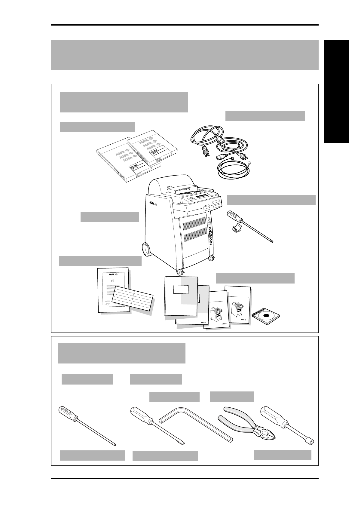
1
Contents of the packages
1 Contents of the packages.
Two film packs
Drystar 4500
A
Set of cables
Unpacking
Phillips screwdriver
Set of documents
DECLARATION OF CONFORMITY
XXXXXX XXXX XXXXXX
XXXXXX XXXX XXXXXX
XXXXXX XXXX XXXXXX
XXXXXX XXXX XXXXXX
XXXXXX XXXX XXXXXX
XXXXXX XXXX XXXXXX
XXXXXX XXXX XXXXXX
XXXXXX XXXX XXXXXX
XXXXXX XXXX XXXXXX
XXXXXX XXXX XXXXXX
XXXXXX XXXX XXXXXX
XXXXXX XXXX XXXXXX
2 Required tools.
Included Not included
Agfa Medical
Agfa Medical
6 mm Allen key
500
4
ar
yst
Dr
ference manual
e
R
Wire cutter
Set of manuals
Drystar4500
User manual
Philips screwdriver
2805F EN 200501282805F EN 20050128
Standard screwdriver
7 mm hex key
3/18
Page 4
A
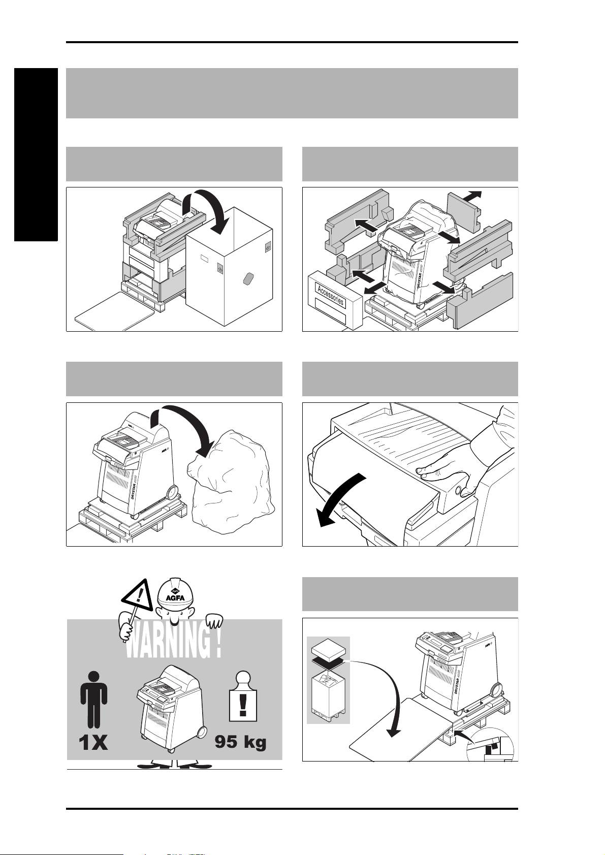
2
Remove the packing materials
1 Remove the cardboard box.
Unpacking
3 Remove the plastic bag.
Accessories
2 Remove the foam blocks.
FRONT SIDE
4 Remove the front panel protection.
4/18
5 Create a descending slope.
2805F EN 20050128
Page 5

3
Unscrew the fixations
A
1 Take 6 mm Allen key.
2 Remove eight screws and two fixation
bars.
1
2
3
4
MOBILE / SEISMIC INSTALLATION ONLY:
reuse the fixation bars and screws to secure
the printer at its final location.
2
1
3
2
Unpacking
MOBILE INSTALL ATION
If the printer is to be installed on a van,
continue unpacking as described and refer
to the illustration when securing the printer
to the van floor.
3 Unlock the wheel brakes.
1
2
4 Pull the printer down the slope and
relock the wheel brakes.
1
2
1
2805F EN 200501282805F EN 20050128
5/18
Page 6
A
Unpacking
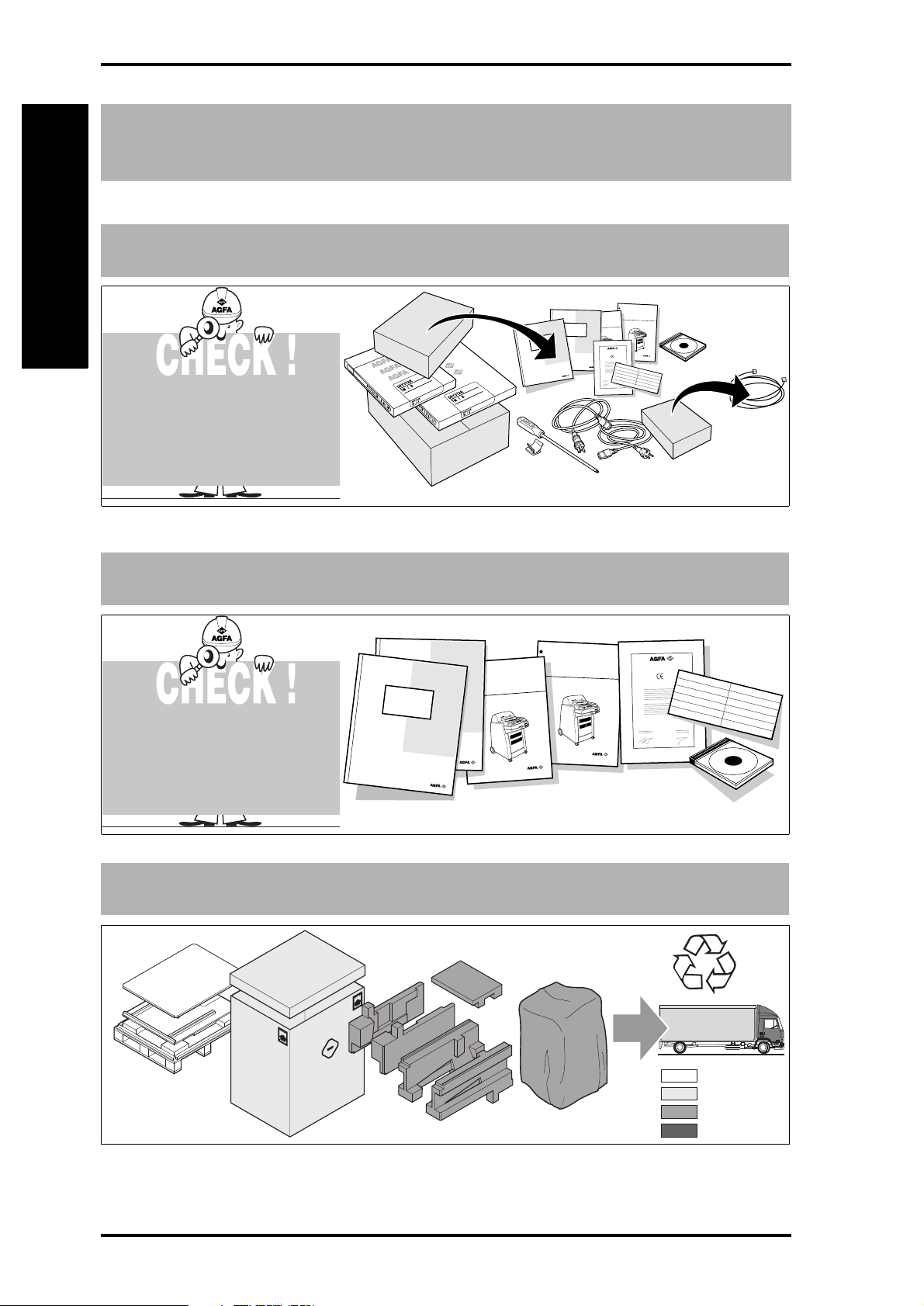
4
Unpack the accessories
1 Check all accessories.
Refer to the Packing slip for
a complete list of
accessories.
2 Check all documents.
D
r
y
s
t
a
r
4
5
0
0
U
s
e
r
m
a
n
u
a
l
R
e
l
e
a
s
e
2
.
0
0
0
45
r
a
t
s
y
r
D
l
a
u
n
a
m
e
c
n
e
r
e
f
e
R
r
e
gh
i
h
r
o
x
.
1
e
s
a
le
e
R
Y
T
I
M
R
O
F
N
O
C
F
O
N
O
I
T
A
R
A
L
C
E
D
A
g
f
a
M
e
d
i
c
a
l
X
X
X
X
X
X
X
X
X
X
X
X
X
X
X
X
X
X
X
X
X
X
X
X
X
X
X
X
X
X
X
X
X
X
X
X
X
X
X
X
X
X
X
X
X
X
l
a
ic
d
e
M
fa
g
A
X
X
X
X
X
X
X
X
X
X
X
X
X
X
X
X
X
X
X
X
X
X
X
X
X
X
X
X
X
X
X
X
X
X
X
X
X
X
X
X
X
X
X
X
X
X
X
X
X
X
X
X
X
X
X
X
X
X
X
X
X
X
X
X
X
X
X
X
X
X
X
X
X
X
X
X
X
X
X
X
X
X
X
X
X
X
X
X
X
X
X
X
X
X
X
X
X
X
X
X
X
X
X
X
X
X
X
X
X
X
X
X
X
X
X
X
X
X
X
X
X
X
X
X
X
X
X
X
X
X
X
X
X
X
X
X
X
X
X
X
X
X
X
X
X
X
Refer to the Packing slip for
a complete list
of documents.
3 Return the packing materials.
I
N
S
T
I
F
P
I
P
R
E
P
R
C
IN
E
T
D
G
C
O
H
N
A
T
S
E
N
O
T
CC
S
U
R
E
D
M
E
D
I
8
I
A
0
0
R
5
E
2
C
7
O
9
V
4
E
9
R
7
Y
U
;
.
S
I
N
.
C
P
D
A
T
A
.
L
N
L
O
A
.
S
;
4
T
,
4
X
3
8
,
7
2
0
5
6
L
l
l
e
d
o
M
/
l
e
d
o
M
R
D
r
y
s
t
a
r
4
5
0
0
U
s
e
r
m
a
n
u
a
0
0
45
r
a
t
s
y
r
D
l
a
u
n
a
m
e
c
n
e
r
e
f
e
R
A
g
f
a
M
e
d
i
c
a
l
A
g
f
a
M
e
d
ic
a
l
R
S
T
D
D
N
E
E
E
T
R
R
N
F
CU
O
I
C
C
O
T
C
S
E
A
P
H
S
N
G
I
N
I
P
P
I
T
X
T
;
S
0
A
2
L
7
L
,
8
A
3
D
4
,
4
C
N
.
I
O
;
N
Y
.
R
T
E
A
V
P
O
.
C
S
.
E
U
R
7
A
I
9
4
D
9
E
7
M
2
5
0
0
8
I
l
D
X
X
X
X
X
X
X
X
X
X
X
X
X
X
X
X
X
X
X
X
X
X
X
X
X
X
X
X
X
X
X
X
X
X
X
X
X
X
X
X
X
X
X
X
X
X
X
X
X
X
X
X
X
X
X
X
X
X
X
X
X
X
X
X
X
X
X
X
X
X
X
X
X
X
X
X
X
X
X
X
X
X
X
X
X
X
X
X
X
X
X
X
X
X
X
X
X
X
X
X
X
X
X
X
X
X
X
X
X
X
X
X
X
X
X
X
X
X
X
X
X
X
X
X
X
X
X
X
X
X
X
X
X
X
X
X
X
X
X
X
X
X
X
X
X
X
X
X
X
X
X
X
X
X
X
X
X
X
X
X
X
X
X
X
X
X
X
X
X
X
X
X
X
X
X
X
X
X
X
X
X
X
X
X
X
X
X
X
X
X
X
X
Y
T
I
M
R
O
F
N
O
C
F
O
N
O
I
T
A
R
A
L
C
E
Wood
Paper
Plastic
Metals
6/18
2805F EN 20050128
Page 7

5
f f
Environment specifications
B
1 Environment requirements.
◆ Ventilated room ,
◆ away from direct sunlight,
◆ away from sources of dust, humidity, heat and
cold,
◆ room temperature between 15°C (50°F) and
30°C (86°F),
◆ relative humidity between 20% and 75% non-
condensing.
4 Space requirements.
2 Power requirements.
◆ The AC outlet must have either o
specifications:
◆ 100-120 V, 60 Hz, 16/15 A,
or
◆ 200-240 V, 50 Hz, 16/15 A.
ollowing
3 Network requirements.
◆ Ethernet/connectors:
RJ45 twisted pair for 10/100Base-TX;Serial
RS232 connection,
◆ Network protocols (TCP/IP services):
FTP, Telnet, HTTP, SNMP, SMTP, LPD, Helios.
Installation
2805F EN 200501282805F EN 20050128
6
0
0
m
m
±
2
4
"
1
0
0
m
m
±
4
"
6
0
0
m
m
±
2
4
"
m
m
0
0
"
6
4
2
±
Space required for normal useSpace required for servicing and installation
m
m
0
0
"
6
4
2
±
m
m
0
0
"
6
4
2
±
7/18
Page 8

B
6
Remove the transport protection blocks
Installation
1 Open the upper input tray
and the top cover.
2
3
3 Close the upper tray and the top cover.
2
2 Remove the protection foam.
1
1
4 Open the lower input tray.
2
5 Remove the protection foam.
1
6 Close the lower input tray.
8/18
2805F EN 20050128
Page 9

7
Remove the protection straps
B
1 Open both input trays and the top cover.
4
2
1
3 Cut the two upper red straps.
3
2 Take wire cutter.
Installation
4 Cut the two lower red straps.
5 Open the film input assembly.
2805F EN 200501282805F EN 20050128
6 Cut the red strap, and close the input
trays and the top cover.
9/18
Page 10

B
8
Remove the side covers
Installation
1 Open the front cover.
3 Take standard screwdriver.
2 Remove the two adhesive straps and
close the front cover.
4 Unlock the quarter turn fastener.
10 /18
5 Push two pins upwards and remove the
right side cover.
2
1
1
6 Remove the left side cover.
3
2
1
2
2805F EN 20050128
Page 11

9
Install blocking plate and belt
B
1 Take 7 mm hex key.
3 On the left, pull the belt [1] over the
pulley [2].
2
1
2 On the right, loosen and refasten the
red blocking plate.
Installation
4 Slowly turn the pulley by hand to assist
the belt.
Turn the pulley only slowly to assist the
mounting of the belt.
If the printer will not be used for a
prolonged time (at least four weeks), it is
recommended to remove the belt during this
period.
2805F EN 200501282805F EN 20050128
11/18
Page 12

B
Installation
10
Reinstall the side covers
1 Install the Phillips screwdriver for
future use.
1
2
When reinstalling the side covers, take into
account the positioning pins at the bottom
and the top.
2 Reinstall the right side cover on the
bottom positioning pins.
4 Reinstall the left side cover.
1
3 Lift the top pins into their positioning
holes.
1
2
2
5 Refasten both quarter turn fasteners
and close the top cover.
12/18
2
2
2805F EN 20050128
Page 13

11
Connect the cables
B
1 Select the power cable.
3 Connect the power cable.
2 Locate the mains connector.
Installation
4 Mount the strain relief.
5 Locate the network connector and
connect the network cable.
2805F EN 200501282805F EN 20050128
6 Move the printer to its final destination
and lock the wheel.
13/18
Page 14

C
Loading films
12
The films delivered with the printer are
Load 8x10” test films in the upper tray and
10x12” test films in the lower tray.
Load film in the upper input tray
intended for test purposes only.
1 Open the upper input tray.
2 Open the 8x10” film pack.
B
0
9
8
Check
the icons
on the
film bag
before
loading films.
2
4 Close the upper input tray (verify that
film is under the retainers).
3 Place the film pack in the tray.
This side down
5 Place the correct film sticker.
14 /18
2805F EN 20050128
Page 15

13
Load film in the lower input tray
C
1 Open the tray and push the partition
clips down (for film size 10x12”).
3 Place the film pack in the tray (with
perforated protective sheet down).
This side down
6 Open the film pack.
B
2
9
8
Check
the icons
on the
film bag
before loading
films.
2
4 Close the lower input tray (verify that
film is under the retainers).
Loading films
5 Place the correct film sticker.
2805F EN 200501282805F EN 20050128
6 Note: for film size 8x10”, lift the
partition clips before loading the film.
15/18
Page 16

D
14
Startup Drystar 4500
1 Press the POWER button.
POWER
Startup
STOP
POWER
2 Wait until the READY status is
displayed.
POWER
STOP
3 Press the lower left corner to open the
keypad cover.
16 /18
2805F EN 20050128
Page 17

15
Configure network settings
E
The printer is configured with the
following APIPA addresses:
Printer IP address: 169.254.10.10
Subnet mask: 255.255.0.0
1 Select and initiate the printer
installation wizard.
1x
6x
1x
1x
1. Press the Key-operator key.
2. Press the Down key six times.
3. Press the Confirm key.
4. Press the Down key once to select
‘Printer install. wizard’.
5. Press the Confirm key.
6. Follow the instructions
Ask your network manager
the following information:
Printer IP address:
Netmask:
Router IP address:
Called AE_Title:
2 Select and initiate printer calibration.
1x
5x
1x
1. Press the Key-operator key.
2. Press the Down key five times to
select ‘Calibration’.
3. Press the Confirm key.
4. Follow the instructions
Network
1x
3 Your Drystar 4500 is ready for use!
2805F EN 200501282805F EN 20050128
17 /18
Page 18

18/18
2805F EN 20050128
 Loading...