

Page 1
DR Software Console, DR Tube
Head Display
User Manual
0389B EN 20180702 1241
Page 2

| DR Software Console, DR Tube Head Display | Contents
ii
Contents
Legal Notice ..........................................................................4
Introduction to this Manual ................................................... 5
Scope of this Manual ..................................................6
Warnings, Cautions, Instructions and Notes ...............7
Disclaimer ................................................................. 8
Introduction to the DR Software Console ............................... 9
Operation Controls .................................................. 10
Image Preview Window ........................................... 12
Tools Window .......................................................... 13
System Documentation ............................................ 14
Labels ...................................................................... 15
System messages ......................................................16
Message types .............................................. 17
Getting started .....................................................................18
Starting the Software Console ..................................19
Starting the Tube Head Display ................................ 19
Stopping the Software Console ................................ 19
Stopping the Tube Head Display ...............................19
Operation ............................................................................ 20
Device Status Frame .................................................21
Preparation ..................................................23
X-Ray On ..................................................... 24
Ready For Exposure Status ...........................25
X-Ray Tube .................................................. 26
Modality Position .........................................27
DR Detector Switch ......................................28
Filter Status ................................................. 29
Grid Status .................................................. 30
Unknown status ........................................... 31
Positioning Controls ................................................ 32
Source image distance (SID) ........................33
X-ray tube angle ...........................................34
X-ray tube stand tracks table height ............. 35
X-ray tube stand tracks wall stand height ..... 36
Generator Controls .................................................. 37
Radiographic Parameters .............................39
Focal Spot Indicator .....................................40
X-Ray Tube Load .......................................... 41
Automatic Exposure Control (AEC) ..............42
DAP Value ....................................................45
Heat Units ....................................................46
Radiographic Working Modes .................................. 47
One Point Mode (1P) ................................... 48
Two Point Mode (2P) ................................... 49
Three Point Mode (3P) ................................ 50
0389B EN 20180702 1241
Page 3

DR Software Console, DR Tube Head Display | Contents | iii
Problem solving ....................................................... 51
Radiographic Parameter Limits .................... 52
Tube head display shows only Agfa logo .......53
Emergency stop button ................................ 54
0389B EN 20180702 1241
Page 4

4 | DR Software Console, DR Tube Head Display | Legal Notice
Legal Notice
0413
Agfa NV, Septestraat 27, B-2640 Mortsel - Belgium
For more information on Agfa products, please visit www.agfa.com.
Agfa and the Agfa rhombus are trademarks of Agfa-Gevaert N.V., Belgium or
its affiliates. DX-D is a trademark of Agfa NV, Belgium or one of its affiliates.
All other trademarks are held by their respective owners and are used in an
editorial fashion with no intention of infringement.
Agfa NV makes no warranties or representation, expressed or implied, with
respect to the accuracy, completeness or usefulness of the information
contained in this document and specifically disclaims warranties of suitability
for any particular purpose. Products and services may not be available for
your local area. Please contact your local sales representative for availability
information. Agfa NV diligently strives to provide as accurate information as
possible, but shall not be responsible for any typographical error. Agfa NV
shall under no circumstances be liable for any damage arising from the use or
inability to use any information, apparatus, method or process disclosed in
this document. Agfa NV reserves the right to make changes to this document
without prior notice. The original version of this document is in English.
Copyright 2018 Agfa NV
All rights reserved.
Published by Agfa NV
B-2640 Mortsel - Belgium.
No part of this document may be reproduced, copied, adapted or transmitted
in any form or by any means without the written permission of Agfa NV
0389B EN 20180702 1241
Page 5

DR Software Console, DR Tube Head Display | Introduction to this Manual | 5
Introduction to this Manual
Topics:
• Scope of this Manual
• Warnings, Cautions, Instructions and Notes
• Disclaimer
0389B EN 20180702 1241
Page 6

6 | DR Software Console, DR Tube Head Display | Introduction to this Manual
Scope of this Manual
This manual contains the information for safe and effective use of the DR
software console and the DR Tube Head Display.
The software is part of a General Radiography X-ray imaging system.
0389B EN 20180702 1241
Page 7

DR Software Console, DR Tube Head Display | Introduction to this Manual | 7
Warnings, Cautions, Instructions and Notes
The following samples show how warnings, cautions, instructions and notes
appear in this document. The text explains their intended use.
Warning: Warnings are directions which, if they are not
followed, can cause fatal or serious injuries to a user,
engineer, patient or any other person or can lead to a
mistreatment.
Caution: Cautions are directions which, if they are not followed,
can cause damage to the equipment described in this manual or
any other equipment or goods and can cause environmental
pollution.
Instruction: This sign is typically used in combination with the
warning sign when providing a specific instruction. If it is followed
exactly, it should avoid the subject of the warning.
Note: Notes provide advice and highlight unusual points. A note is
not intended as an instruction.
0389B EN 20180702 1241
Page 8

8 | DR Software Console, DR Tube Head Display | Introduction to this Manual
Disclaimer
Agfa assumes no liability for use of this document if any unauthorized
changes to the content or format have been made.
Every care has been taken to ensure the accuracy of the information in this
document. However, Agfa assumes no responsibility or liability for errors,
inaccuracies or omissions that may appear in this document. To improve
reliability, function or design Agfa reserves the right to change the product
without further notice. This manual is provided without warranty of any kind,
implied or expressed, including, but not limited to, the implied warranties of
merchantability and fitness for a particular purpose.
Note: In the United States, Federal law restricts this device to sale
by or on the order of a physician.
0389B EN 20180702 1241
Page 9

DR Software Console, DR Tube Head Display | Introduction to the DR Software Console | 9
Introduction to the DR Software Console
Topics:
• Operation Controls
• Image Preview Window
• Tools Window
• System Documentation
• Labels
• System messages
0389B EN 20180702 1241
Page 10
1
2
3
4
5
6
7
9
2
8
6
4
10
11
| DR Software Console, DR Tube Head Display | Introduction to the DR Software Console
10
Operation Controls
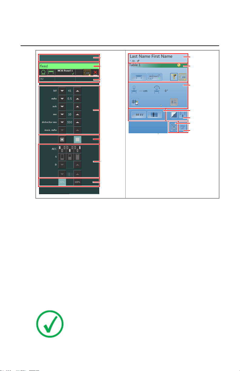
Figure 1: Operation controls
1. Title frame
2. Device status frame
3. Heat units and DAP value
4. Radiographic parameters
5. Focal spot indicator
6. AEC buttons
7. X-ray tube load
8. Positioning controls
9. Patient information
10. Toggle image preview button
11. Tools button
The graphical user interface consists of several panes and toolbars.
Related Links
0389B EN 20180702 1241
Note: The contents of the graphical user interface depends on the
configuration of the X-ray system. The screenshots in this chapter
are examples.
Page 11

DR Software Console, DR Tube Head Display | Introduction to the DR Software Console | 11
Operation on page 20
0389B EN 20180702 1241
Page 12

12 | DR Software Console, DR Tube Head Display | Introduction to the DR Software Console
Image Preview Window
After an exposure, the acquired image is displayed on the tube head display.
To return to the controls, push the display anywhere.
To disable image preview, toggle the Image preview button.
0389B EN 20180702 1241
Page 13

DR Software Console, DR Tube Head Display | Introduction to the DR Software Console | 13
Tools Window
To switch to the tools window on the tube head display, push the Tools button.
The tools window contains a button that temporarily disables the tube head
display to clean the screen during operation.
0389B EN 20180702 1241
Page 14

14 | DR Software Console, DR Tube Head Display | Introduction to the DR Software Console
System Documentation
Refer to the user manual of the DR system for general safety instructions,
system information and instructions for performing a basic workflow.
0389B EN 20180702 1241
Page 15

Agfa NV
DR Software Console, DR Tube Head Display | Introduction to the DR Software Console | 15
Labels
NX has an About box, showing information on version and release of NX and
other software on the NX workstation. To consult the About box, click About
NX... in the Tools section of the Main Menu.
Figure 2: Example of the NX About box
0389B EN 20180702 1241
Page 16

OK
2
1
3
1
3
2
16 | DR Software Console, DR Tube Head Display | Introduction to the DR Software Console
System messages
The system can display messages to the user on the screen. Messages are
displayed on the Software Console and on the Tube head display.
• Device status frame
A message icon is displayed in the device status frame. Click the right half
of the device status frame to display the message frame. To hide the
message frame, click anywhere in the display.
The message frame on the Software Console displays active messages on
top and a history list of messages below. The message frame on the Tube
head display displays active messages only.
• Dialog box
A dialog box is displayed in the middle of the screen. The dialog box can
contain a title, a status description, an instruction for the user and a
button.
Message frame
1.
Dialog box
2.
Device status frame
3.
Figure 3: Messages
Related Links
Tube head display shows only Agfa logo on page 53
0389B EN 20180702 1241
Page 17
DR Software Console, DR Tube Head Display | Introduction to the DR Software Console | 17
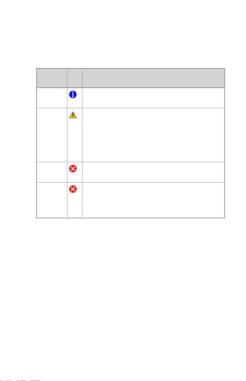
Message types
There are different types of messages. The icon in the device status frame
shows the message type.
Type of
message
Information
Warning
Error
Blocking
error
Messages that require no user response disappear automatically.
Warning or error messages may instruct to contact the Agfa service
organization if the problem repeats, but by following the instructions in the
message, the user can restore the operation of the system.
Icon User response
Information messages help to understand the workflow
status and do not affect safety or efficiency.
Warning messages indicate a difference between the actual status of the system and the status expected based
on the configuration.
Check the message frame for warnings and read the messages carefully. If there's a dialog box, click the button in
the dialog box to continue operation.
A dialog box is displayed. Read the message carefully.
Click the button in the dialog box to continue operation.
A dialog box is displayed. Read the message carefully. It
provides instructions to resolve the problem. Operation is
blocked until the problem is resolved. The dialog box is
closed automatically when the problem is resolved.
0389B EN 20180702 1241
Page 18

18 | DR Software Console, DR Tube Head Display | Getting started
Getting started
Topics:
• Starting the Software Console
• Starting the Tube Head Display
• Stopping the Software Console
• Stopping the Tube Head Display
0389B EN 20180702 1241
Page 19

DR Software Console, DR Tube Head Display | Getting started | 19
Starting the Software Console
The software console software is started automatically when the NX
workstation is switched on.
Starting the Tube Head Display
The tube head display is started automatically when the DR modality is
switched on and becomes operational when the NX workstation is switched
on.
Stopping the Software Console
The software console is stopped automatically when the NX workstation is
switched off.
Stopping the Tube Head Display
The tube head display is stopped automatically when the DR modality is
switched off.
0389B EN 20180702 1241
Page 20

20 | DR Software Console, DR Tube Head Display | Operation
Operation
Topics:
• Device Status Frame
• Positioning Controls
• Generator Controls
• Radiographic Working Modes
• Problem solving
0389B EN 20180702 1241
Page 21

1
2
4
5
6
7 8
3
3
6
7
8
5
DR Software Console, DR Tube Head Display | Operation | 21
Device Status Frame
Figure 4: Device status frame
1. Preparation
2. X-Ray On
3. Ready for Exposure Status
4. X-Ray Tube
5. Modality Position
6. DR Detector Switch
7. Filter Status
8. Grid Status
Topics:
• Preparation
• X-Ray On
• Ready For Exposure Status
• X-Ray Tube
• Modality Position
• DR Detector Switch
• Filter Status
0389B EN 20180702 1241
Page 22

22 | DR Software Console, DR Tube Head Display | Operation
• Grid Status
• Unknown status
0389B EN 20180702 1241
Page 23

DR Software Console, DR Tube Head Display | Operation | 23
Preparation
Table 1: Preparation
Icon Description
The X-ray tube is prepared.
The examination room door is open.
Press the handswitch halfway (“Prep” position) to prepare the X-ray tube for
exposure. The indicator will light up when the X-ray tube is prepared and
there are no interlock failures or system faults.
After pressing this push-button, the following functions are activated:
• Anode rotation.
• Filament current switches from stand-by to the selected mA.
0389B EN 20180702 1241
Page 24

24 | DR Software Console, DR Tube Head Display | Operation
X-Ray On
Figure 5: X-ray on
After pressing the handswitch completely, the X-ray exposure is made. The
indicator on the console will light up.
0389B EN 20180702 1241
Page 25

DR Software Console, DR Tube Head Display | Operation | 25
Ready For Exposure Status
Table 2: Exposure ready
Color Description
Green
Exposure ready. Indicates that the selected technique is properly set
and there are no interlock failures or system faults.
Red
Exposure not ready.
Check the message frame for more information. It is not possible to
perform an exposure due to an error.
The status will turn to green when problem is solved.
Gray
Exposure not ready.
No examination defined.
0389B EN 20180702 1241
Page 26

26 | DR Software Console, DR Tube Head Display | Operation
X-Ray Tube
An icon indicates whether the X-ray system is ready for taking the exposure.
Table 3: Exposure ready
Icon Description
The color of the icon reflects the ready for exposure status.
If multiple tubes can be used, the number of the tube is displayed in the icon.
To select another tube, click the drop-down arrow and select the tube from the
list.
Related Links
Ready For Exposure Status on page 25
0389B EN 20180702 1241
Page 27

DR Software Console, DR Tube Head Display | Operation | 27
Modality Position
The modality position is automatically selected, based on the selected
exposure.
To modify the position on the modality where the exposure will be made, click
the drop-down arrow and select the modality position from the list.
Table 4: Modality Position
Icon
The type and configuration of the X-ray system defines which modality
positions are available.
The available workstations depend on the modality type and configuration.
Description
The image is planned for the radiographic table.
The image is planned for the radiographic wall stand.
The image is planned as a free exposure.
A manual X-ray exposure can be made. No image will be acquired on the NX workstation.
Status icon on Tube Head Display
Table 5: Icon on buttons and status indicators on the tube head display to show
the status of the highlighted component
Icon Description
Error
Warning
0389B EN 20180702 1241
Page 28

?
28 | DR Software Console, DR Tube Head Display | Operation
DR Detector Switch
The DR Detector Switch shows which DR Detector is active and shows its
status. The DR Detector Switch can be used to activate another DR Detector.
The DR Detector Switch can also be used to switch to CR for making an
exposure on a cassette.
Topics:
• DR Detector Status
• DR Detector Status on Tube Head Display
DR Detector Status
Battery status icon
Meaning Full Medium Low Empty
Connection status icon (wifi/
wired)
Meaning Good Low Bad Wired DR Detector
DR detector
status icon
Meaning Ready Initializing expo-
DR Detector Status on Tube Head Display
DR detector status
icon
Meaning Ready Initializing ex-
0389B EN 20180702 1241
(blinking)
sure
posure
Error Sleep One DR detector
must be selected
Error
One DR detector
must be selected
Page 29

DR Software Console, DR Tube Head Display | Operation | 29
Filter Status
On systems with automatic filtering, the filter is automatically set, based on
the selected exposure.
The filter setting can be modified on the software console or on the collimator.
• on the software console, click the filter status drop-down arrow and select
the filter from the list.
• on the collimator, use the filter button
Table 6: Collimator with automatic filter
(no icon)
Table 7: Collimator with manual filter
(no icon)
No filter is used.
A filter is used. Material and thickness of the filter are specified.
No filter is required.
A filter is required. Insert the filter manually.
0389B EN 20180702 1241
Page 30

30 | DR Software Console, DR Tube Head Display | Operation
Grid Status
Table 8: Grid status - automatically detected
(no icon) No grid is required.
The correct grid type is inserted.
The correct grid type is not inserted.
A grid is inserted, but no grid is required.
The SID does not correspond to the inserted grid.
The grid is inserted wrongly.
The grid type is displayed inside the icon.
Table 9: Grid status - not automatically detected
(no icon) No grid is required.
0389B EN 20180702 1241
A grid is required.
Page 31

?
DR Software Console, DR Tube Head Display | Operation | 31
Unknown status
If a status is unknown, a question mark icon is displayed:
Figure 6: Unknown status
Depending on the component for which the unknown status is displayed, an
action is required on the component or on the software to provide the system
with the missing information.
E.g. to solve the unknown detector status, one DR detector must be selected.
0389B EN 20180702 1241
Page 32

Last name, first name
*June 10, 1 960, 081 54711 032,
Chest PA
1 1 3 cm 21 5°
0.1 mm Cu
1 mm Al
Detector table
1
3
2
32 | DR Software Console, DR Tube Head Display | Operation
Positioning Controls
Source image distance (SID)
1.
Tube angle
2.
Tracking
3.
Figure 7: Positioning controls
Topics:
• Source image distance (SID)
• X-ray tube angle
• X-ray tube stand tracks table height
• X-ray tube stand tracks wall stand height
0389B EN 20180702 1241
Page 33

DR Software Console, DR Tube Head Display | Operation | 33
Source image distance (SID)
The icon and reading of the SID depends on the position of the X-ray system.
Table 10: Source image distance (SID)
Icon Value X-ray system position
reading of SID using the bucky of the radiographic table
reading of SID using the bucky of the radiographic wall
stand
(no icon)
or
Related Links
X-ray tube stand tracks table height on page 35
X-ray tube stand tracks wall stand height on page 36
(no value) free exposure
--- cm the X-ray tube is not pointing to the selected DR detector
0389B EN 20180702 1241
Page 34

34 | DR Software Console, DR Tube Head Display | Operation
X-ray tube angle
The icon and reading of the X-ray tube angle depends on the position of the Xray system.
Table 11: X-ray tube angle
Icon Value X-ray system position
reading of tube angle using the bucky of the radiographic table
reading of tube angle using the bucky of the radiographic wall
stand
reading of tube angle free exposure
0389B EN 20180702 1241
Page 35

DR Software Console, DR Tube Head Display | Operation | 35
X-ray tube stand tracks table height
To keep constant SID while adjusting table height:
1. Set the required SID by adjusting the position of the X-ray tube stand.
The distance between the X-ray tube head and the table top must not be
less than 50 cm.
2. On the tube head display, press the position tracking button.
Figure 8: Table position tracking disabled and enabled
The button is highlighted.
3. Adjust the table height.
The X-ray tube stand is moving up or down accordingly.
Note: The movement of the X-ray tube stand has a small delay
compared to the movement of the table. The movement of the Xray tube is automatically stopped if the distance between the Xray tube head and the table would become too small (SID lower
than 45 cm).
Related Links
Emergency stop button on page 54
0389B EN 20180702 1241
Page 36

36 | DR Software Console, DR Tube Head Display | Operation
X-ray tube stand tracks wall stand height
To keep constant position of the tube head unit relative to wall stand bucky
while adjusting wall stand height:
1. Set the required position of the X-ray tube stand.
The distance between the X-ray tube head and the table top must not be
less than 15 cm.
Position the X-ray tube head and the table top such that they do not collide
when the X-ray tube stand moves up or down.
2. On the tube head display, press the position tracking button.
WARNING:
Do not use position tracking while the patient is lying on the
table.
Figure 9: Wall stand position tracking disabled and enabled
The button is highlighted.
3. Adjust the wall stand height.
The X-ray tube stand is moving up or down accordingly.
Related Links
Emergency stop button on page 54
0389B EN 20180702 1241
Note: The movement of the X-ray tube is automatically stopped
if the distance between the X-ray tube head and the table top
would become too small (less than 10 cm).
Page 37

Generator Controls
1
2
3
4
5
Last name, first name
*June 10, 1 960, 081 54711 032,
Chest PA
1 1 3 cm 21 5°
90 kV
+2
0.1 mm Cu
1 mm Al
Detector table
2
4
Last name, first name
*June 10, 1 960, 081 54711 032,
Chest PA
1 1 3 cm 21 5°
0.1 mm Cu
1 mm Al
Detector table
90 kV
DR Software Console, DR Tube Head Display | Operation | 37
1.
2.
3.
4.
5.
Figure 10: Operation controls
To change a value, use the UP and DOWN arrows. On the tube head display,
touch the button to display the arrows. The values increase or decrease step by
step each time the corresponding button is touched, and change faster when
either of them is touched continuously. On the tube head display, touch
elsewhere to hide the arrows.
Figure 11: UP and DOWN arrows on tube head display
Topics:
• Radiographic Parameters
• Focal Spot Indicator
Heat units and DAP value
Radiographic parameters
Focal spot indicator
AEC buttons
X-ray tube load
0389B EN 20180702 1241
Page 38

38 | DR Software Console, DR Tube Head Display | Operation
• X-Ray Tube Load
• Automatic Exposure Control (AEC)
• DAP Value
• Heat Units
0389B EN 20180702 1241
Page 39

DR Software Console, DR Tube Head Display | Operation | 39
Radiographic Parameters
You can set up following radiographic parameters:
• kV: shows the radiographic kV value (X-ray tube voltage) selected for the
exposure.
• mAs can show:
• The radiographic mAs value selected for the exposure.
• When an exposure is made, it shows the actual mAs at the end of the
exposure.
• mA: shows the radiographic mA value (current) selected for the exposure.
• ms can show:
• The time value (in milliseconds) selected for the exposure.
• When an exposure is made, it shows the actual time at the end of the
exposure.
• Detector ms shows the integration time of the DR detector. When
operating the DR detector, the calculated exposure time (ms) or manual
overrides can never exceed the integration time (detector ms) of the DR
detector.
• Max mAs shows the maximum allowed mAs value for exposures using
AEC. The highest allowed setting for max mAs depends on the mA setting
and the detector ms setting. Not available in Free Exposure mode using DR
or Free Exposure mode using CR.
When using AEC, the exposure is terminated by the detector ms or max mAs
settings, even if the target dose is not reached.
Related Links
Radiographic Parameter Limits on page 52
One Point Mode (1P) on page 48
Two Point Mode (2P) on page 49
Three Point Mode (3P) on page 50
0389B EN 20180702 1241
Page 40

40 | DR Software Console, DR Tube Head Display | Operation
Focal Spot Indicator
A focal spot indicator shows the selected focal spot of the X-ray tube: “Small”
or “Large”.
Table 12: Focal Spot Indicator
Small
Large
You can change the focal spot by touching this indicator. It keeps kV and
constant mAs, whenever it is possible. The mA value available is set according
to maximum power, instantaneous power, space charge, etc.
When a focal spot is selected, it sets the highest mA value available for the
selected focal spot and the respective exposure time in order to keep constant
mAs, whenever the mA value does not exceed the maximum tube power and
the exposure time value does not exceed the maximum integration time of the
DR detector or the maximum exposure time of the generator.
0389B EN 20180702 1241
Page 41

DR Software Console, DR Tube Head Display | Operation | 41
X-Ray Tube Load
80% As a way to increase the tube life cycle, the power percentage
of the tube is reduced to a 80% by default.
100% If a specific technique requires 100% of the X-ray tube power,
touch the 100% button.
Depending on the status of the heat units, the system may limit the X-ray tube
load, even when the X-ray tube load is set to 100%.
0389B EN 20180702 1241
Page 42

| DR Software Console, DR Tube Head Display | Operation
42
Automatic Exposure Control (AEC)
Automatic Exposure Control (AEC) produces consistent detector dose
regardless of the radiographic technique selected and of the patient size. The
AEC module comprises the controls for the selection of the exposure detector
fields (ion chamber), S-value and density compensation.
To activate AEC mode, touch any of the three AEC field buttons.
To deactivate AEC mode, touch all the selected AEC field buttons until none of
them is selected.
Related Links
One Point Mode (1P) on page 48
Topics:
• Field Selection
• S-value
• Density
• Patient Size
• AEC dose failure
Field Selection
Each button indicates its related physical location of the selected field in the
AEC exposure detector, and you may select or deselect it by touching it.
Any combination of fields can be selected and the color of the buttons changes
(highlighted) when active. The exposure is ended if any of the selected fields
measures the AEC cut-off dose.
Table 13: Automatic filter
S-value
Each of these buttons allows adjustment of the AEC cut-off dose (low dose,
middle dose and high dose: depending on configuration at installation time).
Each time a button is selected (highlighted), the others are automatically
deselected.
0389B EN 20180702 1241
Left field
Middle field
Right field
Page 43

DR Software Console, DR Tube Head Display | Operation |
Table 14: Automatic filter
S
low dose
middle dose
high dose
Density
These buttons are used to adjust the AEC cut-off dose (and patient entrance
dose accordingly).
Density can be increased and decreased in a range of -4 to +4. Each step is a
change of one exposure step. An exposure step is a change of approximately
-20% or +25% in dose. When disabled, the density range number appears in
black.
Table 15: Dose variation compared to reference dose
43
(D)
Dose
-4 0.41
-3 0.51
-2 0.64
-1 0.80
0 1 (reference dose)
+1 1.25
+2 1.56
+3 1.95
+4 2.44
Patient Size
The size of the patient is classified in five categories: Extra Small, Small,
Medium, Large and Extra Large.
Touch the UP or DOWN arrows to select the desired patient size.
0389B EN 20180702 1241
Page 44

44 | DR Software Console, DR Tube Head Display | Operation
Table 16: kV variation over patient size
Patient size kV
Extra Small normal kV * 0.9
Small normal kV * 0.95
Medium normal kV
Large normal kV * 1.05
Extra Large normal kV * 1.1
AEC dose failure
The AEC dose failure safety device terminates the X-ray exposure when no
radiation is detected in the ion chamber or when the selected parameters
(short backup time/mAs) are not appropriate for an exposure with AEC.
0389B EN 20180702 1241
Page 45

DR Software Console, DR Tube Head Display | Operation | 45
DAP Value
The DAP value shows the radiation value of the last exposure. The radiation
measure is read as DAP value (Dose Area Product) in cGy*cm2 (for example:
DAP 12.22).
A new exposure resets the DAP value.
0389B EN 20180702 1241
Page 46

46 | DR Software Console, DR Tube Head Display | Operation
Heat Units
The status of the heat units is displayed below the X-ray icon.
During exposures, the heat units are calculated and totalled. The heat units
display shows the percentage of the thermal capacity of the X-ray tube that is
used. For example, a display of “HU 0” would indicate that all the heat units
capacity of the X-ray tube remains. A display of "HU 100" would indicate that
maximum heat capacity of the X-ray tube is reached and no exposures can be
made until the tube has cooled down.
0389B EN 20180702 1241
Page 47

DR Software Console, DR Tube Head Display | Operation | 47
Radiographic Working Modes
You can select following radiographic working modes according to the
parameters to be controlled and the degree of automation:
• One Point Mode (1P), by selecting kV. The exposure is controlled by AEC.
• Two Point Mode (2P), by selecting kV and mAs. AEC is disabled.
• Three Point Mode (3P), by selecting kV, mA and exposure time
independently. AEC is disabled.
Topics:
• One Point Mode (1P)
• Two Point Mode (2P)
• Three Point Mode (3P)
0389B EN 20180702 1241
Page 48

48 | DR Software Console, DR Tube Head Display | Operation
One Point Mode (1P)
By selecting one of the AEC field buttons, the one point mode is activated.
The value of kV, mA, max ms, max mAs, the setting of focal spot, density, Svalue, patient size and the selected AEC fields can be adjusted.
The value for mAs and ms is not available.
For accurate AEC operation it may be needed to lower the mA value in order
to obtain longer exposure times. The smallest exposure step is 1 ms.
Disabling all AEC fields will switch to two point mode.
After exposure all values reflect the settings actually used by the generator.
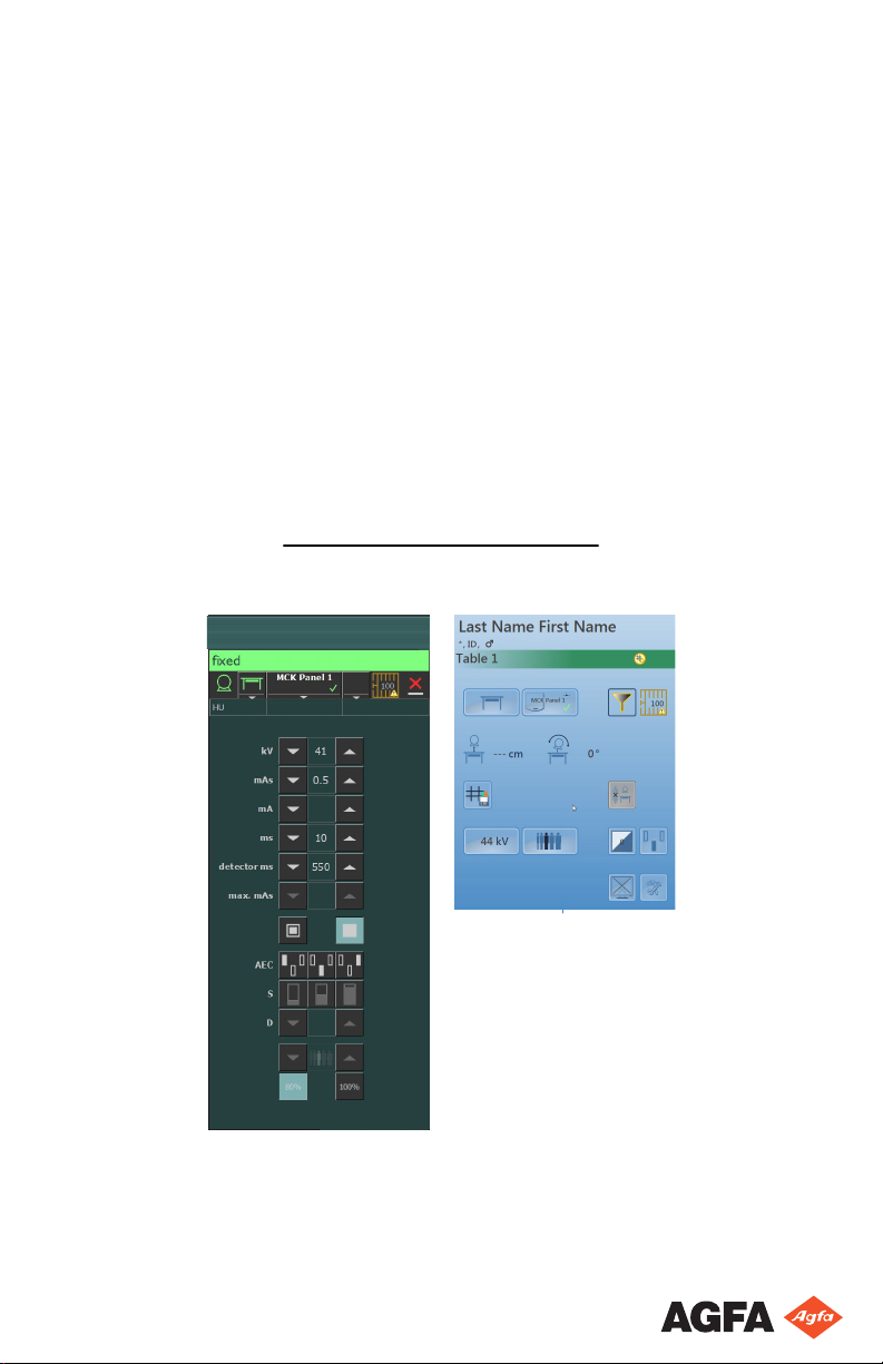
Figure 12: 1P working mode
Related Links
Automatic Exposure Control (AEC) on page 42
One Point Mode on Tube Head Display
Figure 13: 1P working mode
0389B EN 20180702 1241
Page 49

DR Software Console, DR Tube Head Display | Operation | 49
Two Point Mode (2P)
The value of kV, mAs, max ms, the setting of focal spot and X-ray tube load can
be adjusted.
The value of mA and ms are adjusted automatically to keep the mAs value
constant, within the boundaries of generator or X-ray tube limitations.
The setting of density, S-value and patient size is not available.
By selecting one of the AEC field buttons, the one point mode is activated.
By adjusting the value of mA or ms, the three point mode is activated.
After exposure all values reflect the settings actually used by the generator.
Figure 14: 2P working mode
Related Links
Radiographic Parameters on page 39
Two Point Mode and Three Point Mode on Tube Head Display
Figure 15: 2P and 3P working mode
0389B EN 20180702 1241
Page 50

50 | DR Software Console, DR Tube Head Display | Operation
Three Point Mode (3P)
The value of kV, mA and ms can be adjusted. The other values are adjusted
automatically to keep the mAs value constant.
Figure 16: 3P working mode
Two Point Mode and Three Point Mode on Tube Head Display
Figure 17: 2P and 3P working mode
0389B EN 20180702 1241
Page 51

DR Software Console, DR Tube Head Display | Operation | 51
Problem solving
Topics:
• Radiographic Parameter Limits
• Tube head display shows only Agfa logo
• Emergency stop button
0389B EN 20180702 1241
Page 52

52 | DR Software Console, DR Tube Head Display | Operation
Radiographic Parameter Limits
Switching between small focus and large focus may have a delay of a few
seconds to enable the filament to warm up before switching.
The settings of kV and mAs or of mA and ms are defined by an algorithm. The
highest mA setting is used for which the kV can be reached by the system and
the exposure time is not lower than 1 ms or the mAs value is not lower than
0.5 mAs. When the kV setting is changed, the value of mA and ms are adjusted
automatically to keep the mAs value constant, within the boundaries of
generator or X-ray tube limitations.
If the radiographic parameters limits are reached, a value of a radiographic
parameter cannot be increased or decreased, or another value can be
automatically adjusted:
• Radiographic Parameters Limit. A maximum or minimum radiographic
parameter limit is reached. The value cannot be increased or decreased.
• Generator Power Limit. The generator power limit (kV x mA) is reached.
The value of the selected parameter cannot be increased. When increasing
the value of the other parameter, the value of the first parameter will
automatically be decreased to keep the mAs value constant.
• Space Charge. The space charge limit in the selected X-ray tube is reached
by changing the kV or mA values. An information message is displayed.
• Instantaneous Power. The instantaneous power limit of the X-ray tube
(ratings limit or the X-ray tube is momentarily overheated) is reached by
selecting some technique. An information message is displayed.
0389B EN 20180702 1241
Page 53

DR Software Console, DR Tube Head Display | Operation | 53
Tube head display shows only Agfa logo
Details The tube head display shows only the Agfa logo.
Cause The tube head display has no connection to the NX
workstation.
Brief Solution Restart the NX workstation.
0389B EN 20180702 1241
Page 54

54 | DR Software Console, DR Tube Head Display | Operation
Emergency stop button
Figure 18: Emergency stop button
If a system malfunction causes an emergency situation involving the patient,
operating personnel or any system component, activate the emergency stop on
the radiographic table. All motor driven movements will be stopped.
To allow motorized movements again, turn the cap of the emergency switch in
clockwise direction (default position).
Warning: The emergency stop button does not switch off the
voltage in the X-ray system.
0389B EN 20180702 1241
 Loading...