

Page 1
DR 400
5520/100
5520/200
User Manual
3231A EN 20150710 1114
Page 2

| DR 400 | Contents
2
Contents
Legal Notice ..........................................................................5
Introduction .......................................................................... 6
Introduction to this Manual ....................................... 7
Scope of this Manual ......................................8
Warnings, Cautions, Instructions and Notes ....
9
Disclaimer ................................................... 10
Introduction to DR 400 ............................................10
Intended Use ............................................... 11
Intended User .............................................. 12
Configuration .............................................. 13
Equipment Classification ............................. 16
Options and Accessories ...............................17
Operation Controls ...................................... 18
System Documentation ................................27
Training .......................................................28
Product Complaints ..................................... 29
Compatibility ...............................................30
Compliance ................................................. 31
Connectivity ................................................ 33
Installation .................................................. 34
Radiation Protection ....................................35
Labels .......................................................... 40
Cleaning and Disinfecting ............................ 46
Patient data security .................................... 49
Maintenance ................................................50
Environmental protection ............................ 53
Safety Directions ..........................................54
Getting started .....................................................................58
Starting the System ..................................................59
Basic workflow using the DR Detector ......................60
Step 1: retrieve the patient info ....................61
Step 2: select the exposure ...........................62
Step 3: prepare the exposure ........................63
Step 4: check the exposure settings .............. 64
Step 5: execute the exposure ........................65
Step 6: perform a quality control ..................66
Basic workflow using a CR cassette .......................... 67
Step 1: retrieve the patient info ....................68
Step 2: select the exposure ...........................69
Step 3: prepare the exposure ........................70
Step 4: check the exposure settings .............. 71
Step 5: execute the exposure ........................72
Step 6: repeat steps 2 to 5 for the next
subexposures ...............................................73
3231A EN 20150710 1114
Page 3

DR 400 | Contents |
Step 7: digitize the image .............................74
Step 8: perform a quality control ..................75
X-Ray System Positioning ........................................ 76
RAD Table Exposures ...................................77
Oblique Exposures ....................................... 78
Lateral Exposures ........................................ 79
RAD Wall Stand Exposures .......................... 80
Guidelines for Pediatric Applications ....................... 81
Stopping the System ................................................ 83
Operation ............................................................................ 84
Tube head display ....................................................85
RAD Table and X-Ray Tube Stand ............................ 86
Positioning the X-Ray Tube Stand ................ 88
Positioning the RAD Table ........................... 91
Positioning the Bucky .................................. 93
RAD Table Accessories .................................94
RAD Wall Stand .......................................................96
Positioning the RAD Wall Stand ...................98
RAD Wall Stand Accessories .......................101
Bucky .................................................................... 104
Bucky configuration ...................................106
Rotating the bucky .....................................109
Loading of the bucky in the RAD Table .......110
Loading of the bucky in the RAD Wall Stand ....
111
Unloading of the bucky in the RAD Table ... 112
Unloading of the bucky in the RAD Wall Stand .
113
Centering and collimating ..........................114
Orientation of DX-D 10C, DX-D 10G in the bucky
........................................................................116
Grids ......................................................................118
Grid focal distance color indication ............119
Grid detection ............................................120
Storage box for DR Detector and grids ................... 121
Automatic Exposure Control (AEC) ........................122
Manual Collimator .................................................123
Dose Area Product Meter (DAP) .................123
Automatic Collimator ............................................ 125
Semi-automatic collimation mode ............. 127
Manual collimation mode .......................... 128
Dose Area Product Meter (DAP) .................129
Effect of SID on patient dose .................................. 130
X-Ray Generator Console .......................................131
Starting and stopping the generator ...........132
X-ray tube start-up modes ..........................133
X-ray generator messages and warning signals .
134
Exposure parameters ................................. 139
Problem solving .................................................................142
3
3231A EN 20150710 1114
Page 4

4 | DR 400 | Contents
System messages ................................................... 143
Restoring connection between generator and NX after
generator failure ....................................................145
Automatic collimation always too wide or too narrow ..
146
Empty Bucky Failure, Double Exposure Failure ...... 147
NX does not connect to the generator due to ID tablet ..
148
No table movement ................................................149
DR Detector is Exceeding the Maximum Working
Temperature ..........................................................150
DR Detector must be Recalibrated ..........................151
Technical Data ...................................................................152
DR 400 Technical Data .......................................... 153
Environmental conditions ..........................154
Generator Technical Data ...................................... 155
RAD Table and X-Ray Tube Stand Technical Data .. 157
Movement ranges ...................................... 158
RAD Wall Stand Technical Data ............................. 160
X-Ray Tube Technical Data .................................... 162
Bucky Unit Technical Data ..................................... 164
Automatic Exposure Control (AEC) Technical Data ....
166
Ralco R221 Collimator Technical Data ...................167
Ralco R225 ACS Collimator Technical Data ........... 168
Dose Area Product Meter (DAP) Technical Data .....169
DX-D Fixed DR Detector Technical Data .................170
Portable DR Detector Technical Data ..................... 172
NX Workstation Technical Data ............................. 173
DR Generator Sync Box Technical Data ..................174
Remarks for HF-emission and immunity ............................ 175
Remarks for HF-emission and immunity ................ 176
Essential performance ........................................... 182
Cables, transducers and accessories ....................... 183
For type 5520/200 only ............................. 185
Optional .................................................... 185
Stray Radiation ..................................................................186
3231A EN 20150710 1114
Page 5

DR 400 | Legal Notice | 5
Legal Notice
0413
Agfa HealthCare NV, Septestraat 27, B-2640 Mortsel - Belgium
For more information on Agfa products and Agfa HealthCare products, please
visit www.agfa.com.
Agfa and the Agfa rhombus are trademarks of Agfa-Gevaert N.V., Belgium or
its affiliates. DR 400 is a trademark of Agfa HealthCare N.V., Belgium or one
of its affiliates. All other trademarks are held by their respective owners and
are used in an editorial fashion with no intention of infringement.
Agfa HealthCare N.V. makes no warranties or representation, expressed or
implied, with respect to the accuracy, completeness or usefulness of the
information contained in this document and specifically disclaims warranties
of suitability for any particular purpose. Products and services may not be
available for your local area. Please contact your local sales representative for
availability information. Agfa HealthCare N.V. diligently strives to provide as
accurate information as possible, but shall not be responsible for any
typographical error. Agfa HealthCare N.V. shall under no circumstances be
liable for any damage arising from the use or inability to use any information,
apparatus, method or process disclosed in this document. Agfa HealthCare
N.V. reserves the right to make changes to this document without prior notice.
The original version of this document is in English.
Copyright 2015 Agfa HealthCare N.V
All rights reserved.
Published by Agfa HealthCare N.V.
B-2640 Mortsel - Belgium.
No part of this document may be reproduced, copied, adapted or transmitted
in any form or by any means without the written permission of Agfa
HealthCare N.V.
3231A EN 20150710 1114
Page 6

6 | DR 400 | Introduction
Introduction
Topics:
• Introduction to this Manual
• Introduction to DR 400
3231A EN 20150710 1114
Page 7

Introduction to this Manual
Topics:
• Scope of this Manual
• Warnings, Cautions, Instructions and Notes
• Disclaimer
DR 400 | Introduction | 7
3231A EN 20150710 1114
Page 8

8 | DR 400 | Introduction
Scope of this Manual
This User Manual describes the features of the DR 400 System, an integrated
X-Ray imaging system. It explains how the different components of the DR
400 System work together.
3231A EN 20150710 1114
Page 9

DR 400 | Introduction | 9
Warnings, Cautions, Instructions and Notes
The following samples show how warnings, cautions, instructions and notes
appear in this document. The text explains their intended use.
Warning: Warnings are directions which, if they are not
followed, can cause fatal or serious injuries to a user,
engineer, patient or any other person or can lead to a
mistreatment.
Caution: Cautions are directions which, if they are not followed,
can cause damage to the equipment described in this manual or
any other equipment or goods and can cause environmental
pollution.
Instruction: This sign is typically used in combination with the
warning sign when providing a specific instruction. If it is followed
exactly, it should avoid the subject of the warning.
Note: Notes provide advice and highlight unusual points. A note is
not intended as an instruction.
3231A EN 20150710 1114
Page 10

| DR 400 | Introduction
10
Disclaimer
Agfa assumes no liability for use of this document if any unauthorized changes
to the content or format have been made.
Every care has been taken to ensure the accuracy of the information in this
document. However, Agfa assumes no responsibility or liability for errors,
inaccuracies or omissions that may appear in this document. To improve
reliability, function or design Agfa reserves the right to change the product
without further notice. This manual is provided without warranty of any kind,
implied or expressed, including, but not limited to, the implied warranties of
merchantability and fitness for a particular purpose.
Caution: In the United States, Federal law restricts this device to
sale by or on the order of a physician.
Introduction to DR 400
Topics:
• Intended Use
• Intended User
• Configuration
• Equipment Classification
• Options and Accessories
• Operation Controls
• System Documentation
• Training
• Product Complaints
• Compatibility
• Compliance
• Connectivity
• Installation
• Radiation Protection
• Labels
• Cleaning and Disinfecting
• Patient data security
• Maintenance
• Environmental protection
• Safety Directions
3231A EN 20150710 1114
Page 11

DR 400 | Introduction | 11
Intended Use
• The DR 400 system is a General Radiography X-ray imaging system used
in hospitals, clinics and medical practices by physicists, radiographers and
radiologists to make, process and view static X-ray radiographic images of
the skeleton (including skull, spinal column and extremities), chest,
abdomen and other body parts on adult or pediatric patients.
• Applications can be performed with the patient in the sitting, standing or
lying position.
• This device is not intended for mammography applications.
3231A EN 20150710 1114
Page 12

12 | DR 400 | Introduction
Intended User
This manual has been written for trained users of Agfa products and trained
diagnostic X–Ray clinical personnel who have received proper training.
Users are those persons who actually handle the equipment and those who
have authority over the equipment.
Before attempting to work with this equipment, the user must read,
understand, note and strictly observe all warnings, cautions and safety
markings on the equipment.
3231A EN 20150710 1114
Page 13

DR 400 | Introduction |
Configuration
DR 400 is a configurable DR (Direct Radiography X-ray system) or CR
(Computed Radiography) X-ray system.
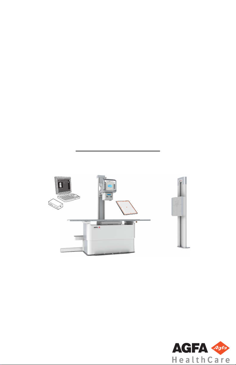
The complete DR 400 consists of the following components:
• RAD Table with an integrated DX-D Fixed DR Detector or with a bucky. In
the bucky a DR Detector or a CR cassette can be inserted.
• RAD Wall Stand with an integrated DX-D Fixed DR Detector or with a
bucky. In the bucky a DR Detector or a CR cassette can be inserted.
• X-ray tube stand mounted on the RAD Table
• X-ray generator integrated in the RAD Table
• X-ray generator console
• X-ray tube with manual or automatic collimator
• NX image processing software on the NX workstation
• DR Generator Sync Box (depending on the configuration)
• Automatic Exposure Control (AEC)
• Dose Area Product Meter (DAP, optional)
Depending on the configuration the following components are also available:
• Portable DR Detector
DR 400 can be used in combination with:
13
• DX-G
• DX-M
• CR 30-X (5175/2XX)
• CR 30-Xm
• CR 10-X
• CR 12-X
• CR 15-X
DR 400 has three main configurations:
1. DR configuration with X-ray exposure parameter control on the NX
workstation.
2. CR configuration with X-ray exposure parameter control on the NX
workstation.
3. Mixed DR and CR configuration with X-ray exposure parameter control on
the NX workstation.
X-ray parameters are controlled using the Software Console on the NX
workstation.
The Software Console is available on the NX workstation, to synchronize the
X-ray exposure parameters between the NX application and the generator.
Other configurable features include:
• Tube head display with controls for X-ray exposure parameters
3231A EN 20150710 1114
Page 14
2
3
6
4
5
1
| DR 400 | Introduction
14
• Position tracking for keeping constand SID on table and wall stand
• Bucky with automatic cassette size sensing (ACSS) and automatic
collimator
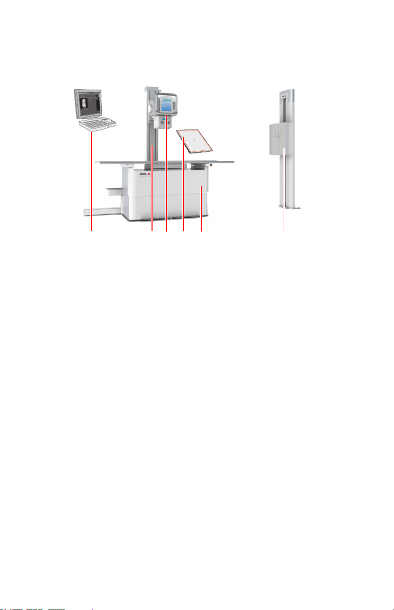
NX workstation
1.
X-ray tube stand mounted on RAD Table
2.
X-ray tube with collimator and tube head display
3.
Portable DR Detector
4.
RAD Table with integrated generator
5.
RAD Wall Stand
6.
Figure 1: DR 400 configuration for DR
Topics:
• Applied Parts
Applied Parts
Applied Parts refer to parts of the medical electrical equipment that in normal
use necessarily comes into physical contact with the patient for the equipment
to perform its function. This system includes the following Applied Parts:
Topics:
• RAD Table
• RAD Wall Stand
• DR Detector
RAD Table
• Table top of the RAD Table
• Patient hand grips (optional)
• Lateral cassette holder (optional)
3231A EN 20150710 1114
Page 15

• Mattress (optional)
• Compression belt (optional)
RAD Wall Stand
• Front panel of the RAD Wall Stand
• Overhead arm support (optional)
• Patient hand grips (optional)
DR Detector
• DR Detector
DR 400 | Introduction | 15
3231A EN 20150710 1114
Page 16

16 | DR 400 | Introduction
Equipment Classification
Per EN/IEC 60601-1:2005, EN/IEC 60601-2-54:2009, this device is classified
as following:
Table 1: Equipment classification
Class I equipment Equipment in which protection against electric
Type B equipment A Type B piece of equipment is one that provides a
Water ingress IP10
Cleaning See section on cleaning and disinfecting.
shock does not rely on basic insulation only, but
includes a fixed connection to mains power with
protective earth conductor.
particular degree of protection against electric
shock particularly regarding allowable leakage
current and reliability of the protective earth
protection.
This device does not have protection against
ingress of water.
Disinfection See section on cleaning and disinfecting.
Flammable anesthetics This device is not suitable for use in the presence of
Operation Continuous operation.
Related Links
Cleaning and Disinfecting on page 46
3231A EN 20150710 1114
a flammable anesthetic mixture with air, or in
presence of a flammable anesthetic mixture with
oxygen or nitrous oxide.
Page 17

DR 400 | Introduction | 17
Options and Accessories
The system is delivered with a set of labels. When using multiple DR
Detectors, on the labels a nickname is written to identify the DR Detector. An
identical label is attached to the bucky of the X-ray system to identify the
dedicated workspace of each DR Detector.
For information on options and accessories of the DR Detector, refer to the
user manual of the DR Detector.
Related Links
RAD Table Accessories on page 94
RAD Wall Stand Accessories on page 101
3231A EN 20150710 1114
Page 18
18 | DR 400 | Introduction
Operation Controls
Topics:
• RAD Table
• RAD Wall Stand
• Control Panel of the X-Ray Tube Stand
• NX Application on the NX Workstation
• Software Console
• DR Detector Switch
• X-ray generator mini console
• Manual collimator
• Automatic collimator
• DR Detector
• Emergency stop button
• Emergency shutdown power switch
RAD Table
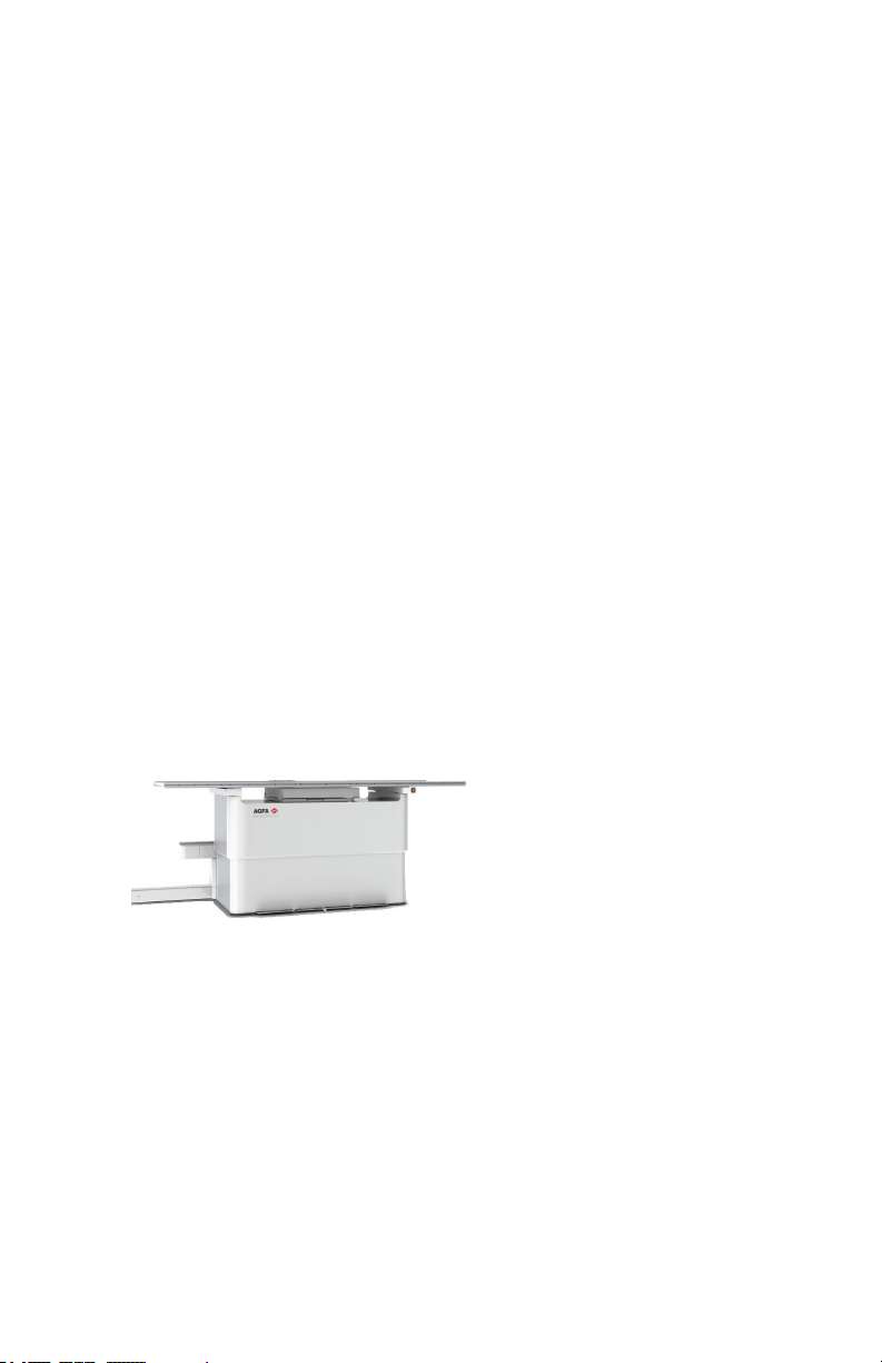
The RAD Table is used for positioning of the patient lying or sitting over the
detector or the cassette in the bucky for exposure.
The RAD Table supports the patient and the detector or the cassette for free
exposure.
Figure 2: RAD Table
Related Links
RAD Table and X-Ray Tube Stand
RAD Wall Stand
The RAD Wall Stand is used for positioning of patients standing upright or
sitting towards the bucky for exposure.
3231A EN 20150710 1114
Page 19
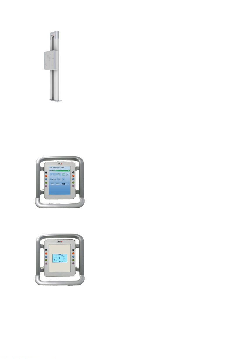
Figure 3: RAD Wall Stand with vertical bucky
Related Links
RAD Wall Stand on page 96
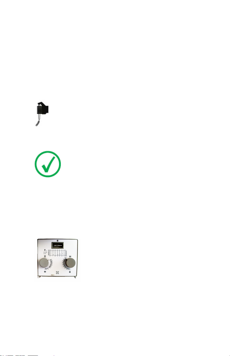
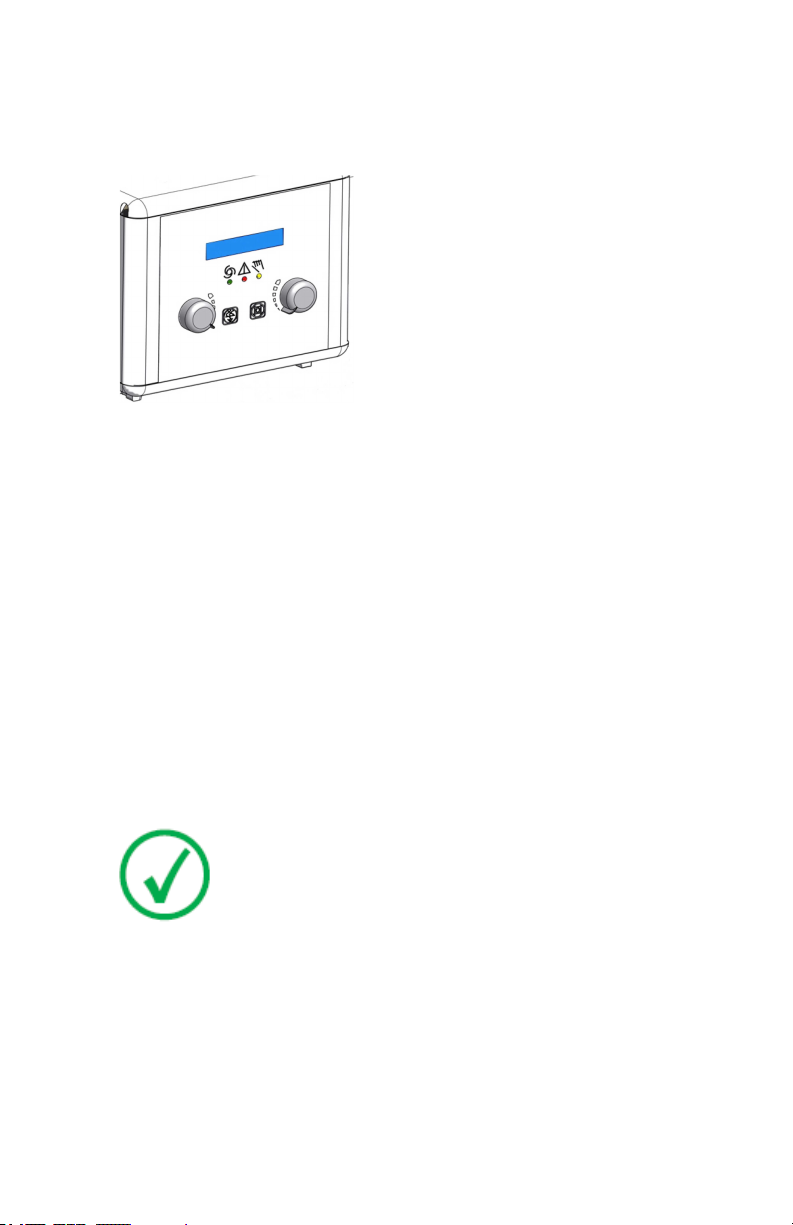
Control Panel of the X-Ray Tube Stand
DR 400 | Introduction | 19
Figure 4: Control Panel of the X-Ray Tube Stand with tube head display
(controls for X-ray tube position and for X-ray exposure parameters)
Figure 5: Control Panel of the X-Ray Tube Stand with X-ray tube angle
display
Related Links
RAD Table and X-Ray Tube Stand on page 86
3231A EN 20150710 1114
Page 20

Last name, first name
*June 10, 1960, 08154711032,
Chest PA
113 cm 35°
114 kV
+2
0.1 mm Cu
1 mm Al
Detector table
| DR 400 | Introduction
20
Tube head display
The tube head display can be used to control X-ray exposure parameters. It
displays the system status.
Figure 6: Example of the tube head display
Related Links
Tube head display on page 85
NX Application on the NX Workstation
The NX application is used to define patient information, select exposures and
process images.
Figure 7: the NX application
Software Console
The Software Console is available to support X-ray exposure parameter
control on the NX workstation. It is displayed on the NX workstation next to
the NX application.
The Software Console is used to control the X-ray exposure settings.
The Software Console contains the DR Detector Switch.
3231A EN 20150710 1114
Page 21
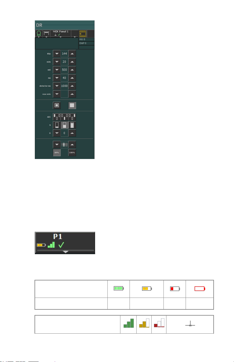
Figure 8: Software Console
DR 400 | Introduction | 21
DR Detector Switch
The DR Detector Switch is available in the device status frame of the Software
Console.
The DR Detector Switch shows which DR Detector is active and shows its
status. The DR Detector Switch can be used to activate another DR Detector.
The DR Detector Switch can be switched to CR, depending on the
configuration.
Figure 9: DR Detector Switch
DR Detector Status
Battery status icon
Meaning Full Medium Low Empty
Connection status icon (wifi/
wired)
3231A EN 20150710 1114
Page 22

?
4 6
1 32
5
8
7
22 | DR 400 | Introduction
DR detector
status icon
Meaning Good Low Bad Wired DR Detector
(blinking)
Meaning Ready Initializing
exposure
Error Sleep One DR detector
X-ray generator mini console
The X-ray generator mini console is available in the operator room.
Power ON button
1.
Power ON indicator
2.
Power OFF button
3.
Press and hold to prepare for exposure
4.
Prepare ready indicator
5.
Press and hold to start the exposure
6.
Radiation indicator
7.
Exposure button
8.
Figure 10: X-ray generator mini console
must be selected
Exposure button
Preparing for exposure
Press the exposure button down to the first pressure point and hold it for
approximately 0.5 s to 2 s.
3231A EN 20150710 1114
Page 23
DR 400 | Introduction |
The X-ray tube is prepared for performing an exposure.
Starting the exposure
Before starting the exposure:
1. Check if the exposure settings displayed on the console are suitable for the
exposure.
2. Check the Ready for Exposure status.
Press the exposure button down fully and keep it pressed until the exposure
has ended.
The radiation indicator on the control console lights up and a signal sounds to
indicate the exposure.
Note: Letting the exposure button go ends the exposure
immediately and the exposure can be underexposed.
23
Manual collimator
The collimator sets the exposure field and displays it by means of a light field.
The collimator provides X-ray filtering using the integrated filters or by
inserting a filter in the rails.
A DAP meter (Dose Area Product Meter) can be mounted on the collimator by
inserting it in the rails.
Figure 11: Collimator
Related Links
Ralco R221 Collimator Technical Data on page 167
Automatic collimator
The collimator sets the exposure field and displays it by means of a light field.
3231A EN 20150710 1114
Page 24
24 | DR 400 | Introduction
The collimator provides X-ray filtering using the integrated filters or by
inserting a filter in the rails.
An integrated DAP meter (Dose Area Product Meter) in the collimator is
available as an option.
Figure 12: Collimator
Related Links
Automatic Collimator on page 125
Automatic Cassette Size Sensing on page 114
Ralco R225 ACS Collimator Technical Data on page 168
DR Detector
When performing an exposure, keep in mind the following detector
orientation aids:
1. Tube side
2. Patient orientation marker
For an overview of the operation controls of the DR Detector, refer to the user
manual of the DR Detector.
The DR Detector may come in contact with the patient.
3231A EN 20150710 1114
Note: DR Detectors that operate wireless contain an RF
transmitter. For detailed information, refer to the DR Detector
User Manual.
Page 25

DR 400 | Introduction | 25
Emergency stop button
Figure 13: Emergency stop button
If a system malfunction causes an emergency situation involving the patient,
operating personnel or any system component, activate the emergency stop
on the RAD Table. All motor driven movements will be stopped.
Motor driven movements:
• RAD Table
• RAD Wall Stand
• X-ray tube stand
To allow motorized movements again, turn the cap of the emergency switch in
clockwise direction (default position).
Warning: The emergency stop button does not switch off the
voltage in the X-ray system.
Emergency shutdown power switch
Use the emergency shutdown power switch, if a dangerous situation cannot
be eliminated by pressing the emergency stop button.
Warning: Use the emergency shutdown power switch in
case of danger to patients, operators, third parties, or one of
the units. The entire system will be shut down and the
power supply will be disconnected.
The emergency shutdown power switch for the room is typically located on
the wall and easy to access, often close to the power off switch of the X-ray
system. It is installed and labeled by customer.
3231A EN 20150710 1114
Page 26

26 | DR 400 | Introduction
Warning: It must be ensured that the emergency switches
are always freely accessible.
3231A EN 20150710 1114
Page 27

DR 400 | Introduction | 27
System Documentation
The DR 400 user documentation consists of
• DR 400 User Documentation CD (digital media)
• NX User Documentation CD (digital media)
The DR 400 User Documentation CD contains:
• DR 400 User Manual (this document)
• DX-D Software Console, DR Tube Head Display User Manual, document
0389
• User manuals for the supported DR Detectors
• DX-D DR Detector Calibration Key User manual, document 0134
Other documentation available on the DR 400 User Documentation CD:
• DAP Datasheet
• X-ray Tube Documentation
• Collimator Datasheet
• AEC Datasheet
• X-ray Generator User Manual
• Test Report for IEC60601-1-3
• Test Report for DIN6868-150
3231A EN 20150710 1114
Page 28

28 | DR 400 | Introduction
Training
The user must have received adequate training on the safe and effective use of
the system before attempting to work with it. Training requirements may vary
from country to country. The user must make sure that training is received in
accordance with local laws or regulations that have the force of law. Your
local Agfa or dealer representative can provide further information on
training.
The user must note the following information in the system documentation:
• Intended Use.
• Intended User.
• Safety Directions.
3231A EN 20150710 1114
Page 29

DR 400 | Introduction | 29
Product Complaints
Any health care professional (for example a customer or a user) who has any
complaints or has experienced any dissatisfaction with the quality, durability,
reliability, safety, effectiveness, or performance of this product must notify
Agfa.
If the device malfunctions and may have caused or contributed to a serious
injury, Agfa must be notified immediately by telephone, fax or written
correspondence to the following address:
Agfa Service Support - local support addresses and phone numbers are listed
on www.agfa.com
Agfa - Septestraat 27, 2640 Mortsel, Belgium
Agfa - Fax +32 3 444 7094
3231A EN 20150710 1114
Page 30

30 | DR 400 | Introduction
Compatibility
The system must only be used in combination with other equipment or
components if these are expressly recognized by Agfa as compatible. A list of
such equipment and components is available from Agfa service on request.
Changes or additions to the equipment must only be carried out by persons
authorized to do so by Agfa. Such changes must comply with best engineering
practice and all applicable laws and regulations that have the force of law
within the jurisdiction of the hospital.
3231A EN 20150710 1114
Page 31

Compliance
The system is compliant with specific directives and standards.
Topics:
• General
• Safety
• Electromagnetic Compatibility
• X-Ray Safety
• X-Ray Accuracy
• Environmental Compliance
• Biocompatibility
General
• The product has been designed in accordance with the MEDDEV
Guidelines relating to the application of Medical Devices and have been
tested as part of the conformity assessment procedures required by
93/42/EEC Medical Device Directive (European Council Directive
93/42/EEC on Medical Devices).
• ISO 13485:2003 + Cor. 1:2009
• ISO 14971:2009
DR 400 | Introduction |
31
Safety
• IEC 60601-1: 2005
• IEC 60601-1-6:2006, EN 60601-1-6:2007
• CSA C22.2 60601-1:2008
• AAMI ES 60601-1:2005
Electromagnetic Compatibility
• IEC 60601-1-2:2007, EN 60601-1-2:2007
Topics:
• For USA
• For Canada
For USA
This equipment has been tested and found to comply with the limits for a
Class A digital device, pursuant to part 15 of the FCC Rules. These limits are
designed to provide reasonable protection against harmful interference when
the equipment is operated in a commercial environment. This equipment
generates, uses, and can radiate radio frequency energy and, if not installed
and used in accordance with the installation manual, may cause harmful
3231A EN 20150710 1114
Page 32

32 | DR 400 | Introduction
interference to radio communications. Operation of this equipment in a
residential area is likely to cause harmful interference in which case the user
will be required to correct the interference at his own expense. If required,
contact your local service organization.
For Canada
This class A digital apparatus meets all requirements of the Canadian
Interference-Causing Equipment Regulations.
X-Ray Safety
• IEC 60601-1-3:2008
• IEC 60601-2-54:2009
• IEC 60601-2-28:2010
For USA
The system conforms to DHHS radiation Standards of 21CFR subchapter J as
of the date of manufacture.
X-Ray Accuracy
The system fulfills the X-ray radiation accuracy according EN IEC 60601-2-54
with a variation of max. 0.05 (5%).
Environmental Compliance
• European Council Directive 1907/2006 (REACH)
• European Council Directive 2011/65/EU (RoHS 2)
• European Council Directive 2012/19/EU (WEEE)
Biocompatibility
• EN ISO 10993-1:2009
3231A EN 20150710 1114
Page 33

DR 400 | Introduction | 33
Connectivity
The NX workstation is connected to the X-ray system to exchange X-ray
exposure parameters.
The NX workstation requires a 100 Mbit ethernet network to exchange
information with a number of other devices.
The NX workstation communicates with other devices in the hospital network
using one of the following protocols:
• DICOM
• IHE
The NX workstation can be connected to a RIS system (input scheduling), a
PACS system (output image/data management) and to a hardcopy device
(output image).
Note: The connections between the components of the system are
separate from the hospital network and should not be disconnected
or modified.
3231A EN 20150710 1114
Page 34

34 | DR 400 | Introduction
Installation
Installation and configuration is performed by an Agfa trained and authorized
service engineer. Contact your local support organization for more
information.
On a configuration with multiple DR Detectors of the same type, it is required
to apply labeling to the DR Detector containing a unique nickname for each
DR Detector. The nicknames must be configured on the NX Workstation. The
DR Detector Switch shows which DR Detector is active and shows its status, by
means of the nickname of the DR Detector.
An identical label is attached to the bucky of the X-ray system to identify the
dedicated workspace of each DR Detector.
HF-emission and immunity
The HF-emission and immunity can be influenced by connected data cables
depending on length and the manner of installation.
A specific installation environment may require special measures to put the
system into operation according to the remarks for HF-emission and
immunity.
Related Links
Cables, transducers and accessories
3231A EN 20150710 1114
Page 35

DR 400 | Introduction |
Radiation Protection
X-ray radiation can cause serious damage to the health, therefore observe
great care and ensure that protection against X-ray exposure is always
applied.
Some of the effects of X-ray radiation are cumulative and may extend over a
period of time. Therefore the X-ray operator should avoid exposure by X-ray
radiation at all times.
Objects in the path of the X-ray beam may produce scattered radiation. The
intensity depends on the energy and intensity of the X-ray exposure and the
material of the object. Protective measures have to be taken to prevent
exposure through scattered radiation.
Protective measures include:
• structural configuration of the X-ray room (e.g. lead shielded rooms)
• radiation protection for the operators (e.g. personal radiation dosimeters,
lead aprons, keep maximum distance from X-ray source, regular training,
etc.)
• protection of patients against unnecessary radiation (e.g. limitation of Xray field by collimation, lead shielding, lead aprons, etc.)
Topics:
35
• Monitoring of Personnel
• Protected area and significant zones of occupancy
Monitoring of Personnel
The monitoring checks the amount of X-ray radiation the personnel has been
exposed to. It determines safety of the operators and it helps checking if safety
measures of the X-ray environment are adequate. Inadequate or improper
protection can lead to serious damage to the health.
To measure radiation, personal radiation dosimeters are typically used. They
are worn on the body at all times during working in an environment where Xray radiation is applied. They provide an indication for the amount of
radiation the operator was exposed to.
Protected area and significant zones of occupancy
If the operator or staff does not need to be close to the patient during the
exposure, the operator and staff use the protected area to control the
following functions:
• selection of mode of operation
• selection of exposure settings (X-ray loading factors)
• actuation of the exposure button
• other necessary controls for the operator during exposure
3231A EN 20150710 1114
Page 36

1
4
3
2
36 | DR 400 | Introduction
X-ray room
1.
Patient environment
2.
Workstation
3.
Operator room: protected area
4.
Figure 14: Protected area and significant zones of occupancy
Warning: The radiation protection has to be applied to the
patient.
If operator or staff needs to be close to the patient during normal use (e.g.
some pediatric examinations or types of examinations for which the patient
requires assistance), the significant zone of occupancy applies for operator
and staff.
Warning: The radiation protection has to be applied to the
patient and to the operator.
Related Links
Radiation Protection on page 35
Topics:
• Significant zones of occupancy at the RAD Table
• Significant zones of occupancy at the RAD Wall Stand
3231A EN 20150710 1114
Page 37

Significant zones of occupancy at the RAD Table
S
SID 100 cm
S3
S4
S5
S
50 cm
4
2
3
1
2
5
2
1
6
8
7
DR 400 | Introduction |
37
X-ray tube
1.
Focal spot label [—]
2.
Significant zone of occupancy.
3.
Minimum area 60x60 cm.
Minimum height above the floor 200 cm.
Dose meter
4.
DR Detector or cassette
5.
Significant zone of occupancy at the left side of the RAD Table
6.
Significant zone of occupancy in front of the RAD Table
7.
Significant zone of occupancy at the right side of the RAD Table
8.
Figure 15: Significant zones of occupancy at the RAD Table
Related Links
3231A EN 20150710 1114
Page 38

140 cm
SID115 cm
Phantom
S1
S2
S
S
50 cm
1
2
3
4
2
5
6
7
2
1
8
9
38 | DR 400 | Introduction
Radiation Protection on page 35
Stray Radiation on page 186
Significant zones of occupancy at the RAD Wall Stand
X-ray tube
1.
Focal spot label [—]
2.
Significant zone of occupancy.
3.
Minimum area 60x60 cm.
Minimum height above the floor 200 cm.
Dose meter
4.
Protective device
5.
Wall
6.
DR Detector or cassette
7.
Significant zone of occupancy at the right side of the RAD Table
8.
3231A EN 20150710 1114
Page 39

Significant zone of occupancy at the left side of the RAD Table
9.
Figure 16: Significant zones of occupancy at the RAD Wall Stand
Warning: The radiation protection has to be applied for the
patient and for the operator.
Related Links
Radiation Protection on page 35
Stray Radiation on page 186
DR 400 | Introduction | 39
3231A EN 20150710 1114
Page 40

| DR 400 | Introduction
40
Labels
Mark Meaning
Label Meaning
This mark shows compliance of the equipment with Directive
93/42/EEC (for European Union).
This mark indicates that this is a Type B Equipment
Serial number
Manufacturer
Date of manufacture
Dangerous voltage
Ionizing radiation
Gaseous disinfectant.
If a disinfectant is used that can form an explosive gaseous
mixture, they must have evaporated and the system must be
aerated before it is switched on again.
Pinch Points.
Risk of stumbling.
Further labels are listed and explained in the relevant modules of the System
Documentation.
Topics:
• Warning labels on the RAD Table
3231A EN 20150710 1114
Page 41

• Warning labels on the RAD Wall Stand
• Type label
• DR Detector identification label
• Additional Labeling of the RAD Table
• Additional Labeling of the RAD Wall Stand
• Labeling of the bucky
• Labeling of the DR Generator Sync Box
Warning labels on the RAD Table
DR 400 | Introduction | 41
Figure 17: Warning labels on the RAD Table
Warning labels on the RAD Wall Stand
Figure 18: Warning labels on the RAD Wall Stand
3231A EN 20150710 1114
Page 42

1
42 | DR 400 | Introduction
Type label
Mark Meaning
(Sample of subtype 5520/100)
Type label positioned on the
lower left hand side of the X-ray
tube stand.
The type label information for
each combination of X-ray tube
and X-ray generator is available
in the technical data.
Note: The CE sign and
safety signs are only
valid at time of product
release.
This mark indicates that this is a
Type B Equipment
Related Links
DR 400 Technical Data on page 153
DR Detector identification label
Label Meaning
3231A EN 20150710 1114
The 21 CFR Subchapter J label is
positioned close to the type label.
Writable label to identify and dedicate a DR Detector to an Xray system bucky.
Page 43

Additional Labeling of the RAD Table
5521/210
Type label on the lower left hand side of the
X-ray tube stand.
The type label information for each
combination of X-ray tube and X-ray
generator is available in the technical data.
(sample of subtype 5521/210)
DR 400 | Introduction | 43
(sample of subtype 5521/410)
This mark indicates that this is a Type B
Equipment
The RAD table is designed for a maximum
patient load of 320 kg.
Related Links
RAD Table and X-Ray Tube Stand Technical Data on page 157
Additional Labeling of the RAD Wall Stand
Type label on the lower right hand side of the
RAD Wall Stand stand
The type label information for each
combination of X-ray tube and X-ray
generator is available in the technical data.
3231A EN 20150710 1114
Page 44

10kg
44 | DR 400 | Introduction
(Sample of subtype
5522/100)
Related Links
RAD Wall Stand Technical Data on page 160
Labeling of the bucky
This mark indicates that this is a Type B
Equipment
Functional earth
The bucky can be tilted to horizontal
position. Do not use the bucky as a seat.
A pinch point label is located on top of the
tilting extension.
The type label is located on the rear cover
of the bucky or on the bucky drawer below
the rotating platform.
The type label information for each bucky
model is available in the technical data.
(Sample of subtype 5523/100)
3231A EN 20150710 1114
Class II equipment.
Pinch Points.
The label is positioned on the lateral cover
of the bucky or on the rotating platform.
Maximum load capacity is 10 kg on the
bucky drawer when it is pulled out. Do not
lean or sit on the bucky.
The label is positioned on the lateral cover
of the bucky or on the rotating platform.
Read the instructions in the user manual.
The label is positioned on the lateral cover
of the bucky or on the rotating platform.
Page 45

Compliance with China RoHS SJ/
T11364-2006. Indication of the
Environment Friendly Use Period (EFUP)
as the period (years) during which the
hazardous substances do not leak or mutate
under normal use.
The label is located on the rear cover of the
bucky or on the bucky drawer below the
rotating platform.
Related Links
Bucky Unit Technical Data on page 164
Labeling of the DR Generator Sync Box
The type label is located on the DR Generator
Sync Box
Functional earth
DR 400 | Introduction | 45
Medical equipotential
3231A EN 20150710 1114
Page 46

46 | DR 400 | Introduction
Cleaning and Disinfecting
All appropriate policies and procedures should be followed to avoid
contamination of the staff, patients and equipment. All existing universal
precautions should be extended to avoid potential contaminations and to
avoid patients coming into (close) contact with the device. The user is
responsible for selecting a disinfection procedure.
Topics:
• Cleaning
• Disinfecting
• Disinfecting safety directions
• Approved disinfectants
Cleaning
To clean the exterior of the equipment:
1. Stop the system
2. Wipe the exterior of the system with a cloth slightly moistened with a
neutral detergent.
Warning: When the equipment is going to be cleaned, be
sure to turn off the main power of the system. Never use
anhydrous or high solvency alcohols, benzine, thinner or
any other flammable cleaning agent. Otherwise, it may
result in fire or electric shock.
Caution: Make sure no liquid gets in the device.
3231A EN 20150710 1114
Caution: Clean the equipment with only a little moisture. Do
not spray disinfectants or detergents directly on the
equipment. Do not pour liquid directly on the equipment.
Caution: Do not use solvents such as anhydrous or high
solvency alcohols, thinner or benzine. Do not use any
corrosive, dissolving or abrasive cleaning or polishing
detergents. Doing so may damage the surface of the
equipment. Using unsuitable cleaning agents or methods can
damage the property when surface becomes dull and brittle.
Page 47

DR 400 | Introduction |
Note: Do not open the equipment for cleaning. No
components inside the device require cleaning by the user.
3. Start up the system.
Cleaning the tube head display during operation
To clean the tube head displayed during operation
1. Press the tools button
Figure 19: Tools button
2. Press the cleaning button
Figure 20: Cleaning button
A black screen hides the screen and shows a number counting down.
3. Clean the display.
The operation is not affected.
4. The display can be used again after the countdown has finished.
47
Disinfecting
To disinfect the device, use only disinfectants and disinfection methods that
are approved by Agfa and that correspond to the national regulation and
guidelines as well as explosion protection. If you plan to use other
disinfectants, approval of Agfa is needed before use, as most disinfectants can
damage the device. UV disinfection is also not allowed.
Perform the procedure following the instructions for use, the disposal
instructions and the safety instructions of the selected disinfectants and tools
and of the hospital.
Disinfecting safety directions
Warning: Using a disinfectant that can form an explosive or
flammable gas mixtures is hazard to life and health because
of explosion risk. Switch the equipment off before
disinfecting. Allow the gas mixture to evaporate before
switching the x-ray system back on.
To disinfect the device:
• Do not use any corrosive, soluble or gaseous disinfectants.
• Use of spray disinfection can cause malfunctions due to ingress of the
disinfectant into the equipment. Disinfect all parts of the unit, including
3231A EN 20150710 1114
Page 48

48 | DR 400 | Introduction
the accessories and connection cables by just wiping them. Switch off the
system and cover the cooled system carefully before performing a room
disinfection using nebuliser.
• Using unsuitable disinfectants can cause discoloration and damage of the
surface of the equipment.
Approved disinfectants
Refer to the Agfa website for specifications on the disinfectants that have been
found compatible with the cover material of the device and can be used on the
outer surface of the device.
http://www.agfahealthcare.com/global/en/main/products_services/
product-info/technology/disinfectants_dx_d_systems.jsp
3231A EN 20150710 1114
Page 49

DR 400 | Introduction | 49
Patient data security
The user must ensure that the patients’ legal requirements are met and that
the security of the patient data is guarded.
The user must define who can access patient data in which situations.
The user must have a strategy available on what to do with patient data in
case of a disaster.
3231A EN 20150710 1114
Page 50

50 | DR 400 | Introduction
Maintenance
Always consult the Agfa Service documentation and an AGFA trained and
authorized Service engineer for complete maintenance schedules.
Topics:
• Maintenance
• Maintenance of the RAD Table, RAD Wall Stand and X-Ray Tube Stand
Maintenance
Always consult the Agfa Service documentation and an Agfa trained and
authorized Service engineer for complete maintenance schedules.
Maintenance of the DR Detector
The DR Detector requires regular calibration. Calibration instructions are
described in the DX-D DR Detector Calibration Key User Manual (doc 0134).
Maintenance of the RAD Table, RAD Wall Stand and X-Ray Tube Stand
The X-ray unit and all components require regular maintenance to ensure the
equipment is safe and reliable for operation.
Warning: Operation in unsafe condition includes the risk of
radiological exposure and injury of the patient and/or the
operator. The customer is responsible to ensure the faultfree condition of the equipment.
3231A EN 20150710 1114
Warning: Improper, irregular or lack of maintenance of the
equipment can lead to injuries to persons (e.g. by radiation
hazard) and property damage as a result of malfunctions
and defects of the equipment.
Warning: Wear of equipment due to excessively long
intervals between service may lead to personal injury and
property damage due to worn and unsafe parts.
Warning: Incorrect or defective spare parts may adversely
affect the safety of the system and lead to damages,
malfunctions or total failure. Use only original spare parts
provided by the manufacturer.
Warning: Improper changes, additions, maintenance or
repair of the system can lead to personal injury and damage
to the equipment. Safety is only guaranteed when changes,
Page 51

DR 400 | Introduction | 51
additions, maintenance or repairs are carried out by an Agfa
certified field service engineer.
Table 2: Lifetime and maintenance
Lifetime
Expected lifetime for the X-ray unit 10 years
Periodic maintenance
The equipment shall have a technical maintenance to
maintain fault-free operation and ensure safety for
patient and operator.
All steel cables of X-ray tube stand and RAD Wall Stand
shall be checked
All steel cables of X-ray tube stand and RAD Wall Stand
shall be exchanged to maintain fault-free operation and
ensure safety for patient and operator
Maintenance by the user
Check constant smooth movements Daily
Check ease of movements Daily
Check secure release and locking of brakes Daily
Check functioning of operating controls Daily
Check markers and warning signs Daily
Warm-up of X-ray tube Daily
Check all electric cables and connections for damage or
broken cables.
Caution: In case of functional defects or other deviations from
normal operation behavior the unit has to be switched off
immediately and the service to be informed. The equipment
must only be put back into operation when the fault has been
repaired.
Caution: The use of spare parts from third party suppliers can
affect the safety of the equipment. If components fail, use only
original spare parts.
Every 12 months
Every 12 months
Every 36 months
Weekly
3231A EN 20150710 1114
Page 52

52 | DR 400 | Introduction
Warming-up of X-ray tube
The X-ray tube needs to be warmed-up before making X-ray exposures at the
start of each day and when the X-ray tube has not been in use for more than an
hour. This extends the X-ray tube lifetime.
To warm-up the X-ray tube
1. Close the collimator blades fully
2. Select 70 kV, 100 mAs, 200 mA and 500 ms exposure settings
3. Ensure that no one will be exposed
4. Make a total of three exposures, 15 seconds apart
This procedure is used for a typical X-ray tube. Consult the X-ray tube
manufacturer instructions for the actual X-ray tube in use and comply with the
instructions if there is conflict with this procedure.
3231A EN 20150710 1114
Page 53

DR 400 | Introduction | 53
Environmental protection
Figure 21: WEEE symbol
Figure 22: Battery symbol
WEEE end user notice
The directive on Waste Electrical and Electronic Equipment (WEEE) aims to
prevent the generation of electric and electronic waste and to promote the
reuse, recycling and other forms of recovery. It therefore requires the
collection of WEEE, recovery and reuse or recycling.
Due to the implementation into national law, specific requirements can be
different within the European Member States. The WEEE symbol on the
products, and/or accompanying documents means that used electrical and
electronic products should not be treated as, or mixed with general household
waste For more detailed information about take-back and recycling of this
product please contact your local service organization and/or dealer. By
ensuring this product is disposed of correctly, you will help prevent potential
negative consequences for the environment and human health, which could
otherwise be caused by inappropriate waste handling of this product. The
recycling of materials will help to conserve natural resources.
Battery notice
The battery symbol on the products, and/or accompanying documents means
that the used batteries should not be treated as, or mixed with general
household waste. The battery symbol on batteries or its packaging may be
used in combination with a chemical symbol. In cases where a chemical
symbol is available it indicates the presence of respective chemical substances.
If your equipment or replaced spare parts contain batteries or accumulators
please dispose of them separately according to local regulations.
For battery replacements please contact your local sales organization.
3231A EN 20150710 1114
Page 54

54 | DR 400 | Introduction
Safety Directions
Topics:
• General Safety Directions
• Safety Directions for the X-Ray System
• Safety Directions for the RAD Table
General Safety Directions
Warning: Strictly observe all warnings, cautions, notes and
safety markings within this document and on the product.
Warning: Safety is only guaranteed when an Agfa certified
field service engineer has installed the product.
Warning: The product must only be installed using released
components and in released configurations.
3231A EN 20150710 1114
Warning: To avoid risk of electric shock, this equipment
must only be connected to a supply mains with protective
earth.
Warning: All Agfa medical products must be used by trained
and qualified personnel.
Warning: Ionizing radiation can lead to radiation injuries if
handled incorrectly. When radiation is applied, the required
protective measures must be complied with.
Warning: The operator and end-user must take precautions
to protect themselves against dangerous X-ray exposure
when using the DR Detector in the X-ray beam path of an Xray source.
Warning: The DR Detector is not intended to be used as a
primary barrier to X-rays. The user is responsible for
ensuring the safety of the operator, bystanders, and the
subjects being radiographed.
Page 55

Warning: Operating the equipment when it is faulty
includes the risk of radiological exposure and injury to the
patient and to the operator. Operate the equipment only in
safe and fault-free conditions.
Safety Directions for the X-Ray System
Warning: Avoid unnecessary dose by checking before
exposure if the DR Detector Switch displays the name of the
DR Detector that is being used and if the status of the DR
Detector is ready for exposure.
Warning: Avoid unnecessary dose by checking the
workstation selection on the X-ray generator console before
exposing. In a configuration with a DR Detector configured
on a virtual port, the DR Detector will not be triggered if a
free exposure is selected on the Generator console and yet
the exposure will be allowed.
Warning: Repeated exposures to a patient with high doses
can lead to deterministic effects. Therefore exposure
settings shall be selected carefully and in accordance to the
patient and the object to expose and balanced in such a way
that patient dose is as low as possible while image quality is
usable for diagnosis.
Warning: Even if the generator is switched off, parts on the
inside of the generator cabinet and connected controls are
still powered! Ensure that only trained service personnel
open the generator cabinet and the housing of connected
devices! Improper handling may cause a lethal hazard!
Caution: When operating the DR detector, the calculated
exposure time (ms) or manual overrides should never exceed
the maximum exposure time (Max ms) specified as integration
time of the DR detector.
DR 400 | Introduction | 55
Caution: Damaged grid. Reduced image quality. Please handle
the grids with special care.
Caution: When inserting the scattered radiation grids, it is
essential that the grid corresponds to the intended sourceimage-distance (SID) to which the grid is focussed. Because of
the focussing of the grids, the tube unit must be centered onto
the bucky.
3231A EN 20150710 1114
Page 56

56 | DR 400 | Introduction
Caution: Excessive ambient temperature may impact
performance of DR Detectors and cause permanent damage to
the equipment. If ambient temperature and humidity is outside
the range specified in the technical data, do not operate the
system or use air conditioning. Warranty will be void if it is
obvious that operating conditions are not met.
Caution: To avoid images being lost due to a power failure, the
workstation and the digitizer have to be connected to an
uninterruptable power supply (UPS) or an institutional standby
generator.
Caution: Install the NX workstation and CR digitizer at a
minimum (safe) distance of 2 m from the X-Ray System
components or provide a wall or window to separate both
systems.
Safety Directions for the RAD Table
Warning: The system is not intended for operation in
explosion-prone areas. Such an operation is hazardous to
life and health because of explosion risk. Please note the
applicable regulations on formation of explosive gas
mixtures when cleaning and using in combination with
patients.
Warning: Unauthorized manipulation or opening of the
equipment housing may lead to personal injuries and to
property damage. Take all necessary precautions with
respect to the applicable level of safety.
3231A EN 20150710 1114
Warning: The system is installed with components that emit
radiation or can be triggered to emit radiation. Ionizing
radiation can result in radiation damage or injury if not
handled properly.
Warning: Portable and mobile HF communication devices
may affect medical electrical equipment.
Caution: Using soft covers, sheets, mattresses, etc. may lead to
visual image artifacts. If such shall be used, make sure that they
are x-ray transparent and do not influence image quality.
Page 57

DR 400 | Introduction | 57
Caution: Make sure that the patient hand grips are securely
mounted.
3231A EN 20150710 1114
Page 58

58 | DR 400 | Getting started
Getting started
Topics:
• Starting the System
• Basic workflow using the DR Detector
• Basic workflow using a CR cassette
• X-Ray System Positioning
• Guidelines for Pediatric Applications
• Stopping the System
3231A EN 20150710 1114
Page 59

DR 400 | Getting started | 59
Starting the System
To start the system:
Note: Allow the DR Detector to warm up before the system is used
for clinical purposes. The warming-up time starts as soon as the DR
Detector has been powered on and the NX workstation is running.
To check if a warming-up time is required, refer to the DR Detector
User Manual.
1. Switch on the electrical room switch.
Check that the emergency shutdown power switch for the system and the
emergency stop button for the RAD Table is not activated.
2. Press the Power ON button on the X-ray generator control box to switch on
the system.
3. Start the NX workstation.
The NX application and the software console are available on the NX
workstation.
For detailed information about starting up NX, refer to the NX User
Manual, document 4420.
4. Switch on the DR Generator Sync (if applicable).
5. In a configuration with a wireless DR Detector, power on the DR Detector:
• attach a fully charged battery pack to the DR Detector.
• turn on the DR Detector.
• if needed, register the DR Detector to the NX workstation.
For detailed information about starting up the DR Detector, refer to the
DR Detector User Manual.
6. Switch on the control unit for the DR Detector.
3231A EN 20150710 1114
Page 60

60 | DR 400 | Getting started
Basic workflow using the DR Detector
Topics:
• Step 1: retrieve the patient info
• Step 2: select the exposure
• Step 3: prepare the exposure
• Step 4: check the exposure settings
• Step 5: execute the exposure
• Step 6: perform a quality control
3231A EN 20150710 1114
Page 61

DR 400 | Getting started | 61
Step 1: retrieve the patient info
At the NX workstation:
1. When a new patient comes in, define the patient info for the exam.
2. Start the exam.
3231A EN 20150710 1114
Page 62

62 | DR 400 | Getting started
Step 2: select the exposure
In the operator room:
At the NX workstation, select the thumbnail for the exposure in the Image
Overview pane of the Examination window.
The default X-Ray exposure parameters for the selected exposure are sent
to the modality and displayed on the Software Console.
The selected DR Detector is activated.
The RAD Table or RAD Wall Stand lights up in blue, indicating the
selected modality position.
The DR Detector Switch shows which DR Detector is active and shows its
status.
• Red (flashing): starting up
• Green (constant): ready for exposure
3231A EN 20150710 1114
Page 63

DR 400 | Getting started | 63
Step 3: prepare the exposure
In the examination room:
1. Position the DR Detector.
When using the bucky, check that the identification labels on the DR
Detector and on the bucky match. Do not use a DR Detector that is
dedicated to another bucky.
2. Position the patient.
Apply radiation protective measures for the patient if needed.
3. Check if the X-Ray system position is suitable for the exposure.
4. Position the X-Ray tube with respect to the DR Detector and the patient.
5. Set the correct distance between DR Detector and X-Ray tube.
6. Switch on the light on the collimator. Adapt collimation if required.
Take care that the collimated area is not larger than the detector.
Warning: Monitor the patient position (hands, feet, fingers,
etc.) with special care to avoid injury to the patient caused
by unit movements. Patient hands must be kept away from
mobile components of the unit. Intravenous tubing,
catheters and other patient connected lines should be
routed away from moving equipment.
3231A EN 20150710 1114
Page 64

64 | DR 400 | Getting started
Step 4: check the exposure settings
Related Links
DR Detector Switch on page 21
On the NX application:
1. Check if the DR Detector Switch displays the name of the DR Detector
that's being used
2. If a wrong DR Detector is displayed, select the right DR Detector by
clicking the drop down arrow on the DR Detector Switch.
3. Check if the status of the DR Detector is ready for exposure.
On a DR Detector that has a status indicator:
Check if the status of the DR Detector is ready for exposure. If the status is
not ready for exposure, the DR Detector cannot be used for making an
exposure.
In the operator room on the Software Console:
1. Check if the exposure settings displayed on the console are suitable for the
exposure.
2. Check the Ready for Exposure status.
3231A EN 20150710 1114
Page 65

Step 5: execute the exposure
In the operator room:
Press the exposure button to execute the exposure.
Instruction: Make sure the generator is ready for exposure
before you press the exposure button.
Warning: During exposure ionizing radiation is emitted
by the X-ray system. To indicate the presence of ionizing
radiation, the radiation indicator on the control console
lights up.
Warning: Do not select another thumbnail until the
preview image is visible in the active thumbnail.
In the operator room at the NX workstation:
• While the acquisition is ongoing, the thumbnail status indicator is
flashing green. The image is acquired from the DR detector and
displayed in the thumbnail.
• The actual X-Ray exposure parameters are sent back from the
generator to the NX workstation and are shown in the Image Detail
pane.
• If collimation is applied, the image is automatically cropped at the
collimation borders.
DR 400 | Getting started | 65
3231A EN 20150710 1114
Page 66

66 | DR 400 | Getting started
Step 6: perform a quality control
At the NX workstation:
1. Select the image on which quality control is to be performed.
2. Prepare the image for diagnosis by using e.g. L/R markers or annotations.
3. If the image is OK, send the image to a hardcopy printer and/or PACS
(Picture Archiving and Communication System).
3231A EN 20150710 1114
Page 67

Basic workflow using a CR cassette
Note: Using an ID Tablet to identify cassettes before the exposure
will break the communication of X-ray parameters between the NX
workstation and the X-ray generator console. It is advised to
identify cassettes after the exposure, as described in this workflow.
Topics:
• Step 1: retrieve the patient info
• Step 2: select the exposure
• Step 3: prepare the exposure
• Step 4: check the exposure settings
• Step 5: execute the exposure
• Step 6: repeat steps 2 to 5 for the next subexposures
• Step 7: digitize the image
• Step 8: perform a quality control
DR 400 | Getting started | 67
3231A EN 20150710 1114
Page 68

68 | DR 400 | Getting started
Step 1: retrieve the patient info
At the NX workstation:
1. When a new patient comes in, define the patient info for the exam.
2. Start the exam.
3231A EN 20150710 1114
Page 69

DR 400 | Getting started | 69
Step 2: select the exposure
In the operator room at the NX workstation:
1. Select the thumbnail for the exposure in the Image Overview pane of the
Examination window.
2. Select CR in the Detector Switch.
3. Select the Modality Position (RAD Table, RAD Wall Stand, Free exposure)
in the Software Console.
The default X-Ray exposure parameters for the selected exposure are sent
to the modality and displayed on the software console.
The RAD Table or RAD Wall Stand lights up in blue, indicating the
selected modality position.
4. Select the subexposure if more than one image is required for the same
cassette.
If an image thumbnail is configured for multiple exposures on a single
cassette, another set of thumbnails is shown in the image detail pane. Now
you have to select one of these thumbnails to send the proper default XRay exposure parameters to the modality for each exposure.
Note: When working in a PACS environment, the preferred
workflow is to have only one image per cassette. This is needed
for optimal use of hanging protocols. However, in particular
cases (e.g. printing sites) it is supported to make more than one
exposure per cassette.
3231A EN 20150710 1114
Page 70

70 | DR 400 | Getting started
Step 3: prepare the exposure
In the examination room:
1. Position the cassette.
2. Position the patient.
Apply radiation protective measures for the patient if needed.
3. Check if the X-Ray system position is suitable for the exposure.
4. Position the X-Ray tube with respect to the cassette and the patient.
5. Set the correct distance between cassette and X-Ray tube.
6. Switch on the light on the collimator. Adapt collimation if required.
Take care that the collimated area is not larger than the cassette.
Note: For a free exposure, partial lead covering of the
cassette may be required if multiple images are taken on one
cassette.
Note: For a bucky exposure, always insert an unexposed
cassette in the bucky.
3231A EN 20150710 1114
Warning: Monitor the patient position (hands, feet, fingers,
etc.) with special care to avoid injury to the patient caused
by unit movements. Patient hands must be kept away from
mobile components of the unit. Intravenous tubing,
catheters and other patient connected lines should be
routed away from moving equipment.
Page 71

DR 400 | Getting started | 71
Step 4: check the exposure settings
In the operator room on the Software Console:
1. Check if the exposure settings displayed on the console are suitable for the
exposure.
2. Check the Ready for Exposure status.
3231A EN 20150710 1114
Page 72

72 | DR 400 | Getting started
Step 5: execute the exposure
In the operator room:
Press the exposure button to execute the exposure.
Warning: During exposure ionizing radiation is emitted by
the X-ray system. To indicate the presence of ionizing
radiation, the radiation indicator on the control console
lights up.
• The actual X-Ray exposure parameters are sent back from the generator to
the NX workstation and are shown in the Image Detail pane.
• The actual X-Ray exposure parameters and the Exposure Index (EI) value
on the NX workstation can be used to monitor the performance of the
Automatic Exposure Control of the X-Ray system.
• A green OK mark appears on all thumbnails for which the exposures are
made and for which exposure settings are sent back to the NX workstation.
3231A EN 20150710 1114
Page 73

DR 400 | Getting started | 73
Step 6: repeat steps 2 to 5 for the next subexposures
3231A EN 20150710 1114
Page 74

74 | DR 400 | Getting started
Step 7: digitize the image
In the examination room:
Take the exposed cassette.
In the operator room:
1. Insert the cassette in the digitizer.
2. Click ID in the examination window of NX.
The image will appear in the image overview pane of the examination
window.
Note: You can also use an ID Tablet to identify the cassette
and digitize it using any digitizer.
3231A EN 20150710 1114
Page 75

DR 400 | Getting started | 75
Step 8: perform a quality control
In the operator room at the NX workstation:
1. Select the image on which quality control is to be performed.
2. Prepare the image for diagnosis by using e.g. L/R markers or annotations.
3. If the image is OK, send the image to a hardcopy printer and/or PACS
(Picture Archiving and Communication System).
3231A EN 20150710 1114
Page 76

76 | DR 400 | Getting started
X-Ray System Positioning
Topics:
• RAD Table Exposures
• Oblique Exposures
• Lateral Exposures
• RAD Wall Stand Exposures
3231A EN 20150710 1114
Page 77

DR 400 | Getting started | 77
RAD Table Exposures
1. Position the patient on the RAD table.
2. Position the X-ray tube stand with the X-ray tube over the patient.
The bucky is automatically aligned to the X-ray tube by mechanical
coupling.
3. Center the examined body part over the bucky using the floating table top.
Figure 23: RAD Table Exposures
3231A EN 20150710 1114
Page 78

78 | DR 400 | Getting started
Oblique Exposures
1. Position the patient on the RAD Table.
2. Move the X-ray tube stand out of the coupling range of the bucky.
3. Position the bucky under the patient.
4. Set the required angle of the X-ray tube.
5. Adjust the position of the X-ray tube stand to align the X-ray exposure field
to the center of the bucky using the collimator light and the bucky markers
for orientation.
Figure 24: Oblique Exposures
3231A EN 20150710 1114
Page 79

DR 400 | Getting started | 79
Lateral Exposures
1. Unlock the X-ray tube arm and rotate 90° around.
2. Rotate the X-Ray tube 90° around.
Check the angle on the angle display.
3. Mount the lateral cassette holder on the side rail of the tabletop. Fix it
using the two lower screws. Take care to lift the holders slightly up when
moving it, to protect the tabletop from scratching.
4. Insert a cassette or a DR detector. Fix it using the upper screw.
5. Position the patient on the table between the X-ray tube and the lateral
cassette holder. Adjust the lateral cassette holder to position the cassette
as close as possible to the patient. Fix the position using the middle screw.
Figure 25: Lateral Exposures
3231A EN 20150710 1114
Page 80

80 | DR 400 | Getting started
RAD Wall Stand Exposures
1. Adjust the height of the bucky on the RAD Wall Stand.
2. Position the patient in front of the RAD Wall Stand.
3. Move the table top away from the RAD Wall Stand.
4. Rotate the X-ray tube 90° to face the RAD Wall Stand.
Check the angle on the angle display.
5. Move the X-ray tube stand towards the RAD Wall Stand.
6. Adjust the height of the X-ray tube to center the X-ray exposure field on
the bucky using the collimator light.
Figure 26: RAD Wall Stand Exposures
3231A EN 20150710 1114
Page 81

DR 400 | Getting started |
Guidelines for Pediatric Applications
Caution: Children are more radiosensitive than adults. Adopting
the Image Gently campaign guidelines and reducing dose for
radiographic procedures while maintaining acceptable clinical
image quality will benefit patients.
Please review the following link and reduce pediatric technique factors
accordingly: http://www.pedrad.org/associations/5364/ig/
As a general rule, next recommendations shall be observed in pediatrics:
• X-Ray Generator must have short exposures times.
• ΑΕC must be used carefully, preferably use manual technique setting,
applying lower doses.
• If possible, use high kVp techniques.
Positioning the pediatric patient: Pediatric patients are not as likely as adults
to understand the need to remain still during the procedure. Therefore it
makes sense to provide aids to maintaining stable positioning. It is strongly
recommended the use of immobilizing devices such as bean bags and restraint
systems (foam wedges, adhesive tapes, etc.) to avoid the need of repeating
exposures due to the movement of the pediatric patients. Whenever possible
use techniques based on the lowest exposure times.
Shielding: We recommend you provide extra shielding of radiosensitive
organs or tissues such as eyes, gonads and thyroid glands. Applying a correct
collimation will help to protect the patient against excessive radiation as well.
Please review the following scientific literature regarding pediatric
radiosensitivity: GROSSMAN, Herman. “Radiation Protection in Diagnostic
Radiography of Children”. Pediatric Radiology, Vol. 51, (No. 1): 141--144,
January, 1973:
http://pediatrics.aappublications.org/cgi/reprint/51/1/141.
Technique factors: You should take steps to reduce technique factors to the
lowest possible levels consistent with good image acquisition.
For example if your adult abdomen settings are: 70--85 kVp, 200--400 mA,
15--80 mAs, consider starting at 65--75 kVp, 100--160 mA, 2.5--10 mAs for a
pediatric patient. Whenever possible use high kVp techniques and large SID
(Source Image Distance).
Summary:
81
• Image only when there is a clear medical benefit.
• Image only the indicated area.
• Use the lowest amount of radiation for adequate imaging based on size of
the child (reducing tube output -- kVp and mAs).
• Try to use always short exposure times, large SID values and immobilizing
devices.
3231A EN 20150710 1114
Page 82

82 | DR 400 | Getting started
• Avoid multiple scans and use alternative diagnostic studies (such as
ultrasound or MRI) when possible.
3231A EN 20150710 1114
Page 83

DR 400 | Getting started | 83
Stopping the System
To stop the system:
1. Stop the NX workstation.
NX can be stopped in two ways, either by logging out of Windows or
without logging out of Windows.
For detailed information on stopping NX, refer to the NX User Manual,
document 4420.
Note: Stopping the NX workstation does not stop the DR
Detector. If the power of the DR Detector remains on, no
warming-up time will be needed after starting the NX
workstation.
2. Press the Power OFF button on the X-ray generator control box to switch
off the generator.
3. In a configuration with a wireless DR Detector, power off the DR Detector:
• turn off the DR Detector.
• remove the battery pack.
4. Switch off the DR Generator Sync.
Note: If the DR Detector is powered down, a warming-up may be
required on the next start-up.
3231A EN 20150710 1114
Page 84

84 | DR 400 | Operation
Operation
Topics:
• Tube head display
• RAD Table and X-Ray Tube Stand
• RAD Wall Stand
• Bucky
• Grids
• Storage box for DR Detector and grids
• Automatic Exposure Control (AEC)
• Manual Collimator
• Automatic Collimator
• Effect of SID on patient dose
• X-Ray Generator Console
3231A EN 20150710 1114
Page 85

Tube head display
Last name, first name
*June 10, 1960, 08154711032,
Chest PA
113 cm 35°
114 kV
+2
0.1 mm Cu
1 mm Al
Detector table
1
2
3
4
5
6
7
8
9
11
12
Patient information
1.
Status bar with exam type
2.
Modality position
3.
DR Detector Switch
4.
Grid status
5.
Filter status
6.
Source Image Distance (SID)
7.
X-ray tube angle
8.
Position tracking status
9.
Radiographic parameters
10.
Image preview
11.
Tools
12.
DR 400 | Operation | 85
Figure 27: Example of the tube head display
For detailed information, refer to the DR Software Console and Tube Head
Display User Manual (document 0389).
3231A EN 20150710 1114
Page 86

1 2 753 64
8
9
10
11
86 | DR 400 | Operation
RAD Table and X-Ray Tube Stand
The RAD Table with integrated X-ray tube stand allows X-ray examinations
from head to foot of lying or sitting patients.
The tube stand has two variants, depending on the side where the tube stand
rail is protruding:
• Left hand version
• Right hand version
The table has two variants:
• table with fixed height
• elevating table with adjustable height
The table has a floating table top.
The table has blue LED in the table foot that is lit when the RAD Table is
selected as active workstation.
Rail system
1.
X-ray tube stand with SID ruler
2.
Bucky
3.
Tabletop movement pedals,
3231A EN 20150710 1114
4.
Blue LED indicator light for active workstation
Table covers with standard exposure height marker
5.
Emergency stop button
6.
Tabletop
7.
Collimator
8.
X-ray tube arm
9.
X-ray tube
10.
Page 87

2 31
2 31
DR 400 | Operation | 87
Control panel of the X-ray tube stand
11.
Figure 28: RAD Table with integrated X-ray tube stand, example of left hand
version
Movement control buttons
1.
Tube head display
2.
Handle with integrated release button for omni direction movement.
3.
Figure 29: Control panel of the X-ray tube stand
Depending on the configuration, an extra control button for omni direction
movement is available on the lower side of the handle.
Movement control buttons
1.
X-ray tube angle display
2.
Handle
3.
Figure 30: Control panel of the X-ray tube stand
Topics:
• Positioning the X-Ray Tube Stand
• Positioning the RAD Table
• Positioning the Bucky
• RAD Table Accessories
3231A EN 20150710 1114
Page 88

110
115
120
105
100
95
88 | DR 400 | Operation
Positioning the X-Ray Tube Stand
The operation controls of the X-ray tube stand are located at the control panel.
The X-ray tube stand must be positioned by the operator manually.
To release the brake for the selected movement direction or rotation, press
and hold the button and move the X-ray tube stand.
To stop the movement and activate the brake, release the button.
Table 3: Movement controls
Omni direction movement (longitudinal, vertical and alpha
rotation)
Transversal axis movement (back & front).
A marker on the X-ray tube arm indicates the center position.
Vertical axis movement (up & down)
A ruler on the X-ray tube stand indicates the SID when the
RAD Table is positioned on the standard exposure height.
The lower edge of the X-ray tube arm mounting is used for
reference.
3231A EN 20150710 1114
Longitudinal axis movement (right & left)
Alpha axis rotation (Angle of the X-ray tube)
Beta axis rotation (swivel of the X-ray tube arm around the
tube stand axis)
Page 89

DR 400 | Operation |
Rotation of the collimator around the axis of the X-ray beam
The standard position of the X-ray tube arm is indicated by markers. When the
tube arm is in standard position it is centered in transversal direction on the
bucky.
Note: To avoid shock and damage, move the column with
normal speed and slow down when reaching the mechanical
end stops.
Caution: If a grinding noise is heard during vertical movement
of the X-ray tube arm or RAD Wall Stand, the steel cables inside
the tube stand or wall stand could be broken. Do not operate the
unit any further and try to avoid hard vibration or knocks of any
kind. Please contact service.
Caution: Rotation may be limited by cables. Avoid strain on the
cables during rotation.
89
Related Links
Movement ranges on page 158
Ralco R221 Collimator Technical Data on page 167
Ralco R225 ACS Collimator Technical Data on page 168
Positioning the Bucky on page 93
Topics:
• Stop positions
• Collision indicator
Stop positions
The system includes stop positions.
• On the longitudinal axis movement, to position the X-ray tube in regularly
used exposure distances to the RAD Wall Stand, e.g. 150 cm and 180 cm.
• On the vertical axis movement, to position the X-ray tube stand in
regularly used exposure distances to the RAD Table, e.g. 115 cm.
The preferred positions of the stops are defined during installation.
3231A EN 20150710 1114
Page 90

90 | DR 400 | Operation
The vertical stop on the tube stand is always active. The two transversal stops
are active when the X-ray tube is rotated towards the wall stand (90°+/- 10°).
To enter a stop position, move the X-ray tube stand or the X-ray tube arm in
longitudinal or vertical direction. The movement is stopped when the stop
position is reached. Moving too fast may cause the X-ray tube stand to skip the
stop position.
To leave a stop position, release and press again the according movement
control button.
Collision indicator
Systems with motorized movement have a collision indicator. The collision
indicator avoids collision of the X-ray tube head with the table.
The collision indicator will give a signal in following situations:
• The X-ray tube head is moved manually close than 30 cm to the table top
when performing an examination using the table.
• The X-ray tube head is moved manually closer than 15 cm to the table top
when performing an examination using the wall stand and the X-ray tube
head is rotated toward the wall stand.
The brake is activated and a single beep indicates the collision warning.
To further adjust the position, release the brake button and press it again.
Related Links
X-ray tube stand tracks wall stand height on page 99
3231A EN 20150710 1114
Page 91

DR 400 | Operation | 91
Positioning the RAD Table
There are two versions of the RAD table:
• Fixed height RAD Table with a height of 70 cm
• Elevating RAD Table with adjustable height from 55 cm to 90 cm
The movements of the RAD table are controlled by foot pedals mounted at
front side of the table.
Warning: Maintain visual contact with the patient while
moving the equipment close to the patient in order to detect
hazardous situations (e.g. collisions) early and to avoid
them.
Warning: Make sure that no persons or objects are within
the movement area of the system where they can collide
with moving parts of the system.
Positioning the floating tabletop
To release the brake for moving the floating tabletop, double click and hold
the foot pedal. The tabletop can be moved in longitudinal and transversal
direction manually.
To stop movement and activate the brake, release the foot pedal.
Table 4: Movement controls
Foot pedal to release the brake for the floating table top.
Note: When the equipment is switched off, the tabletop can be
moved freely. Pay extra attention when a patient needs to get
off from the table.
The RAD table is designed for a maximum patient load of 320 kg.
Adjusting height
To adjust the height, double click and hold the foot pedal.
Table 5: Movement controls
Foot pedal to lower table height (minimum 55 cm).
3231A EN 20150710 1114
Page 92

92 | DR 400 | Operation
When minimum or maximum position of the table is reached, the movement
is stopped automatically.
When the standard exposure height (70 cm) is reached, the movement is
stopped automatically. To continue the movement, release the foot pedal and
double click it again.
Markers on both sides of the table covers indicate the standard exposure
height position.
Figure 31: Standard exposure height
Foot pedal to raise table height (maximum 90 cm).
Related Links
Collision protection on page 94
Collision indicator on page 90
Emergency stop button on page 25
X-ray tube stand tracks table height
To keep constant SID while adjusting table height:
1. Set the required SID by adjusting the position of the X-ray tube stand.
The distance between the X-ray tube head and the table top must not be
less than 50 cm.
2. On the tube head display, press the position tracking button.
Figure 32: Table position tracking disabled and enabled
The button is highlighted.
3. Adjust the table height.
The X-ray tube stand is moving up or down accordingly.
Note: The movement of the X-ray tube stand has a small delay
compared to the movement of the table. The movement of the
X-ray tube is automatically stopped if the distance between the
X-ray tube head and the table would become too small (SID
lower than 45 cm).
3231A EN 20150710 1114
Page 93

DR 400 | Operation | 93
Positioning the Bucky
The bucky center position is automatically aligned to the position of the X-ray
tube stand. The mechanical coupling between the bucky and the X-ray tube
stand is active within the travel range of the bucky.
The bucky can be positioned independently from the X-ray tube stand, e.g. for
oblique X-ray exposures.
To position the bucky independently from the X-ray tube stand:
1. Move the X-ray tube stand on the longitudinal axis outside the travel range
of the bucky.
The mechanical coupling is released.
2. Press and hold the bucky lock switch.
Figure 33: Bucky lock switch
The lock for the bucky movement is released.
3. Move the bucky in longitudinal direction.
4. Release the bucky lock switch.
The position is locked.
3231A EN 20150710 1114
Page 94

1
| DR 400 | Operation
94
RAD Table Accessories
Caution: Using wrong accessories that cannot be properly
attached to the system can lead to hazardous situations and
injury. Use only original accessories provided by the
manufacturer.
Topics:
• Mounting the patient hand grips
• Collision protection
• Other RAD Table accessories
Mounting the patient hand grips
The pair of patient hand grips are used to stabilize the patient and give a
feeling of security. Using the hand grips will avoid the patient grasping the
table edges which could cause a risk to pinch fingers.
To mount a hand grip:
1. Slide the hand grip in the rails of the tabletop.
2. Tighten the hand screw to lock the hand grip in position.
Hand screw
1.
Figure 34: Hand grip
Collision protection
Collision protection is only available on the elevating RAD Table.
The collision protection accessories are mounted on the frame of the RAD
Table. They protect the tabletop from damage when colliding with objects
below.
When the collision protection stops downward movement of the RAD table,
raise the table height and remove the object before lowering the table again.
3231A EN 20150710 1114
Note: The hand grips are not intended to support the weight of
the patient.
Page 95

Note: The collision protection is influenced by the patient
1
weight. Take special care when moving the RAD Table with a
patient lying on.
Figure 35: Location of the collision protection accessories
Other RAD Table accessories
On request further accessories for the RAD table are available:
• Mattress
The mattress fits the tabletop (220 cm x 80 cm) and is X-ray translucent.
• Lateral cassette holder
The lateral cassette holder supports a cassette or detector in lateral
position and is attached to the tabletop.
DR 400 | Operation | 95
Figure 36: Lateral cassette holder
• Compression belt
The compression belt provides additional fixation for the patient on the
table. It can be adjusted to patient thickness.
Figure 37: Compression belt
3231A EN 20150710 1114
Page 96

1
6
8
7
5
2
3
4
| DR 400 | Operation
96
RAD Wall Stand
The RAD Wall Stand allows vertical X-ray exposures of patients standing or
sitting in front of the RAD Wall Stand.
The wall stand has two variants:
• wall stand with vertical bucky, supporting vertical movement (up and
down)
• wall stand with tilting bucky, supporting vertical movement (up and
down) and tilting of the bucky
The bucky has two variants, depending on the orientation for loading a
detector or cassette:
• Right hand side loading
• Left hand side loading
The wall stand bucky is height adjustable in a large range.
The wall stand has blue LED in the top that is lit when the RAD Wall Stand is
selected as active workstation.
3231A EN 20150710 1114
Wall Stand column
1.
Active workstation indicator
2.
Bucky
3.
Button to switch on the collimator light
4.
Front panel
5.
Page 97

Vertical movement handle (both sides)
6.
Tilting extension
7.
Tilting handle
8.
Figure 38: RAD Wall Stand, vertical version and vertical tilting version
Caution: The format indications on the front panel show the
format of the cassette or detector. Take into account that the
actual area for imaging is smaller than indicated. The image of
the exposed object is slightly magnified because there is a
distance between the front panel and the cassette or detector.
The sensitive area of the cassette or detector may be slightly
smaller than the indicated area. Check the technical data of the
cassette or detector for exact values.
Topics:
• Positioning the RAD Wall Stand
• RAD Wall Stand Accessories
DR 400 | Operation | 97
3231A EN 20150710 1114
Page 98

1
2 3
98 | DR 400 | Operation
Positioning the RAD Wall Stand
Vertical movement handle with brake switch
1.
Tilting angle scale
2.
Tilting handle
3.
Figure 39: Positioning controls
Warning: Maintain visual contact with the patient while
moving the equipment close to the patient in order to detect
hazardous situations (e.g. collisions) early and to avoid
them.
Vertical movement
To release the brake for vertical movement, press the switch that is integrated
at the upper side of the handle located at the left and right side of the RAD
Wall Stand. The bucky can be moved up and down.
To stop movement and lock the bucky into position, release the switch.
3231A EN 20150710 1114
Warning: Make sure that no persons or objects are within
the movement area of the system where they can collide
with moving parts of the system.
Warning: Be careful not to squeeze your finger or hand.
Keep your hands at the handles while positioning the
system.
Page 99

DR 400 | Operation |
Caution: The maximum load for the bucky movement in vertical
direction is 20 kg. The bucky may slip downward when applying
excessive load.
Note: Do not move the bucky with excessive force to the end
stop positions.
99
Tilting
To tilt the bucky, press and hold the button on the tilting handle and move the
bucky. The scale for the angle is visible at the mounting point of the bucky.
To lock the bucky into position, release the button on the tilting handle.
Note: The bucky can be tilted to horizontal position. Do not use
the bucky as a seat.
X-ray tube stand tracks wall stand height
To keep constant position of the tube head unit relative to wall stand bucky
while adjusting wall stand height:
1. Set the required position of the X-ray tube stand.
The distance between the X-ray tube head and the table top must not be
less than 15 cm.
Position the X-ray tube head and the table top such that they do not collide
when the X-ray tube stand moves up or down.
2. On the tube head display, press the position tracking button.
Warning: Do not use position tracking while the patient
is lying on the table.
Figure 40: Wall stand position tracking disabled and enabled
The button is highlighted.
3. Adjust the wall stand height.
3231A EN 20150710 1114
Page 100

100 | DR 400 | Operation
The X-ray tube stand is moving up or down accordingly.
Related Links
Collision indicator on page 90
Emergency stop button on page 25
Note: The movement of the X-ray tube is automatically stopped
if the distance between the X-ray tube head and the table top
would become too small (less than 10 cm).
3231A EN 20150710 1114
 Loading...