


Aircraft Operation Manual
Piper Cheyenne I, IA, II, IIXL
PA31T
Piper Cheyenne
I, IA, II and IIXL
Add-On for Microsoft Flight Simulator X
The manual, documentation, video images, software, and all the related materials are copyrighted and can not be copied, photocopied, translated or reduced to any electronic medium or machine legible form, neither completely nor in part, without the previous written consent of AEROSOFT. THE SOFTWARE IS FURNISHED «AS IS» AND IT DOES NOT COME FURNISHED WITH ANY GUARANTEE IMPLICIT OR EXPRESS. THE AUTHOR DECLINES EVERY RESPONSIBILITY FOR CONTINGENT MALFUNCTIONS, DECELERATION, AND ANY DRAWBACK THAT SHOULD ARISE, USING THIS SOFTWARE.
Copyright © 2006 AEROSOFT All rights reserved.
Microsoft Windows, Windows® 95, Windows® 98, Windows ME, Windows® NT, Windows® 2000, Windows XP and Flight Simulator are either registered trademarks or trademarks of Microsoft Corporation in the United States and/or other Countries. All trademarks and brand names are trademarks or registered trademarks of the respective owners. Copyrights are serious stuff. If you find any pirated copies of this software please notify us at info@aerosoft.com We will make sure reports of copyrights violations are rewarded.
Aerosoft GmbH
Lindberghring 12
D-33142 Büren, Germany
www.aerosoft.com
For flight simulation use only |
Page 3 |

Aircraft Operation Manual
Piper Cheyenne I, IA, II, IIXL
TABLE OF CONTENTS
TABLE OF CONTENTS............................................................................................... |
4 |
INTRODUCTION........................................................................................................ |
5 |
CONFIGURATION...................................................................................................... |
7 |
BASICS OF OPERATION.......................................................................................... |
11 |
FREQUENTLY ASKED QUESTIONS (FAQ)............................................................... |
14 |
GENERAL DATA...................................................................................................... |
15 |
Abbrevations and Terminology..................................................................... |
17 |
INSTRUMENT PANELS............................................................................................ |
22 |
INSTRUMENT PANELS - Views........................................................................ |
23 |
INSTRUMENT PANELS - Panel navigation by clickspots:............................... |
27 |
INSTRUMENT PANELS - Overview.................................................................. |
29 |
Primary Instruments - Pilot panel.................................................................. |
35 |
Engine instruments........................................................................................ |
39 |
Secondary instruments - Pilot panel.............................................................. |
40 |
Cockpit Instruments - Copilot panel.............................................................. |
42 |
Environmental Controls - Copilot.................................................................. |
46 |
AUTOMATED FLIGHT............................................................................................. |
50 |
BENDIX-KING AVIONICS SUITE (RADIOS).............................................................. |
64 |
TRIMBLE 2000 APPROACH PLUS GPS.................................................................... |
77 |
PRESSURIZATION SYSTEM..................................................................................... |
82 |
TCAS (with digital VSI only).................................................................................. |
85 |
Flight Tutorial......................................................................................................... |
88 |
Page 4 |
For flight simulation use only |

Aircraft Operation Manual
Piper Cheyenne I, IA, II, IIXL
INTRODUCTION
Thank you for purchasing the Piper Cheyenne by Digital Aviation and Aerosoft. We hope that you will have as much fun with it as we had while creating it. For many years, the Cheyenne series of business aircraft was one of the most successful for Piper. It started in the mid sixties, when Piper decided to redesign its pressurized model „Navajo” to accommodate propeller turbines as propulsion.
On August 29th 1969 the prototype took off for his maiden flight, but it took almost another five years until the first production aircraft went into service. The control surfaces and flight controls had to be reworked several times, because the higher speeds were a strain to the cell. Furthermore, a flooding of Pipers production facility in Lock Haven delayed deliveries.
On October 22nd 1973, the maiden flight of the first production aircraft Piper
Cheyenne PA31T took place – powered by two Pratt&Whitney PT6A-28s engines, developing 620hp each. When Piper expanded the family in 1978 with a decreased variant (PT6A-11, 500hp), they renamed the initial aircraft in „Cheyenne II” and the new variant became “Cheyenne I”. Improvements like more power, redesigned cowlings and a new interior lead to the „Cheyenne IA”. In addition to that, Piper stretched the Cheyenne II and built in a fourth cabin window. Equipped with PT6A-135s (750hp) engines and an increased MTOW by 180kg/400lb
– this variant became the „Cheyenne IIXL”. In total, 823 Cheyennes had been built, 526 Cheyenne and Cheyenne II, 215 Cheyenne I and IA, and 82 IIXL, when the production was discontinued in the mid eighties. Even twenty years later, the PA31T models have an excellent reputation for being spacious, uncomplicated and reliable aircraft and therefore enjoy great popularity.
Our add-on features all four mentioned variants, each in three liveries from different countries. All models possess a highly detailed 2D-panel with various view options, a completely functional 3D cockpit with virtual cabin, two different sound sets and of course a true to the original model with many ground objects, like Ground Power Unit, towing equipment, chock blocks and pylons. The in-
For flight simulation use only |
Page 5 |

Aircraft Operation Manual
Piper Cheyenne I, IA, II, IIXL
strumentation is an exact rendition of its real counterparts, based on the „Silver Crown Plus” avionics suite by Bendix-King. Autopilot is either the KFC250 or the KFC300 by Bendix-King, depending on the model you choose. The pressurization controllers are models by Dukes and Garret. A configuration program is provided to help with individual settings.
And now we wish you many pleasant hours with our Piper Cheyenne Add-On for the Microsoft Flight Simulator.
Page 6 |
For flight simulation use only |
Aircraft Operation Manual
Piper Cheyenne I, IA, II, IIXL
CONFIGURATION
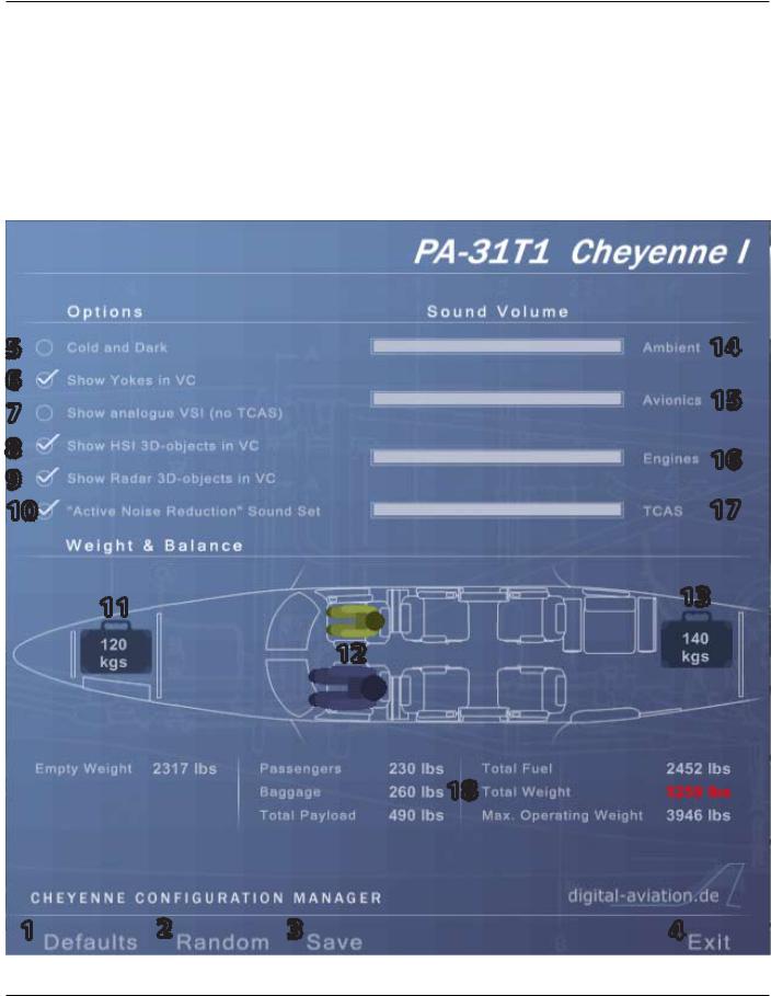
The Piper Cheyenne can be fully configured using the supplied configuration manager. The configuration manager is opened from inside the aircraft by using the key combination SHIFT-7:
5 |
14 |
|
6 |
15 |
|
7 |
||
|
||
8 |
16 |
|
9 |
||
17 |
||
10 |
11 |
13 |
|
12
18
1 |
2 |
3 |
4 |
For flight simulation use only |
Page 7 |

Aircraft Operation Manual
Piper Cheyenne I, IA, II, IIXL
Saving your settings
Your configuration settings may be either saved to disk using the SAVE button
(3) or applied to the currently loaded aircraft only, using the button EXIT (4). When using the SAVE option, the aircraft CFG file of the selected aircraft will be also updated, to pertain the changes for the next time you start Microsoft Flight Simulator. Using the button DEFAULT all configuration options are reverted to their default values, while RANDOM (2) creates a random aircraft loading.
Options
The OPTIONS section in the upper left part of the configuration manager offers some advanced configuration options:
5:Cold and Dark
Loads the aircraft in a „cold & dark” configuration next time. All systems are off, and you may work through the complete startup procedure.
6:Show yoke in VC
Selecting this option displays the yoke in the virtual cockpit also. You may want to deselect this option to get easier access to some switches near the yoke.
7:Show analogue VSI (no TCAS)
Selecting this option displays an analogue vertical speed indicator instead of the default digital one. In this case no TCAS is available.
8:Show HSI 3D objects in VC
Deselecting this option displays the HSI as a 2D object instead of a 3D object in the virtual cockpit. This may increase performance on low-end systems. Also, it may be necessary when adding a third-party HSI instead of the supllied one.
9:Show Radar 3D objects in VC
Deselecting this option displays the radar as a 2D object instead of a 3D object in the virtual cockpit. This is necessary if you want to add a third-party weather radar at this place.
10:„Active Noise Reduction” (ANR) Sound Set
When using the ANR sound set, the internal engine sound is greatly muffled, as the pilot would hear it while wearing Active Noise Reduction (ANR) head-
Page 8 |
For flight simulation use only |

Aircraft Operation Manual
Piper Cheyenne I, IA, II, IIXL
phones. Almost all pilots wear these or similar headphones today in order to protect their hearing and ease communication over the radios. It is very rare to see these aircraft flown without the pilot and passengers wearing headphones.
NOTE: After changing the sound set the aircraft needs to be manually reloaded.
Weight and Balance
The Weight and Balance section (11-13) offers the possibility to individually configure the loading and seating of the aircraft. The forward and aft baggage compartments may be loaded in steps of 10 lbs., and different crew members and passengers may be placed in any available seat:
Children: 60 lbs.
Women: 135 lbs.
Men: 170 lbs.
Please note that for the pilot and copilot seats, only men or women may be selected.
A detailed weights listing (18) is displayed just below the load editor. If the loading is within limits, the TOTAL WEIGHT value is displayed in green. Overweights are displayed in red.
Sounds volume
For flight simulation use only |
Page 9 |

Aircraft Operation Manual
Piper Cheyenne I, IA, II, IIXL
Four sliders are available to individually configure different portions of the sound set:
14:Ambient sounds volume
Adjusts the volume level for click sounds and other background noises
15:Avionics sounds volume
Sets the volume level for aural alerts and warnings
16:Engines sounds volume
Configures the volume level of the engine startup
17:TCAS
Adjusts the volume level for the TCAS TA and RA sounds
Page 10 |
For flight simulation use only |
Aircraft Operation Manual
Piper Cheyenne I, IA, II, IIXL
BASICS OF OPERATION
Panel operation
Microsoft Flight Simulator traditionally depends heavily upon mouse actions to operate buttons, switches and knobs. Sometimes, click spots may not be 100% intuitive, or the result of your action may depend upon clicking with the left or right mouse button at the correct location. When familiarizing yourself with the panel, it is suggested that you turn on „tool tips”. These tips will then appear when you hold your cursor over the various click spots, and the tips will describe what each click spot is for. Tool tips can be activated under the FS menu under Options / Settings / General.
The Piper Cheyenne uses a consistent, standardized approach to operate the different controls in the aircraft panels. Following is an overview about these methods to interact with the controls in the 2D and 3D panels:
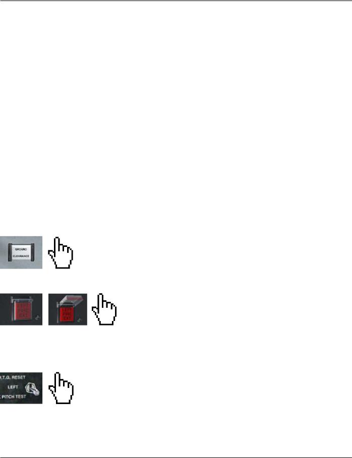
Push buttons: Left or right-click to operate these buttons on/off.
Guarded buttons: Guarded buttons require two steps: First, right-click to open or close the guard covering the control. Second, left-click to operate the button underneath. The cursor will show a solid hand.
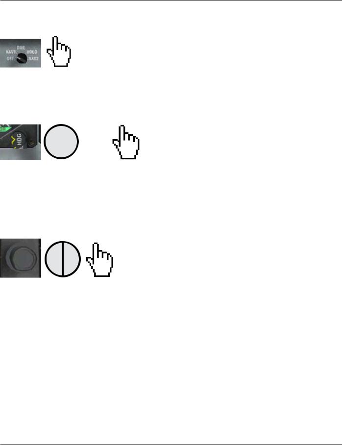
Multi-position switches: Multi-position switches have more than one position, and may be turned left/down or up/right. Left-click to move the switch to the left or down, and right-click of right/up movement.
For flight simulation use only |
Page 11 |
Aircraft Operation Manual
Piper Cheyenne I, IA, II, IIXL
NOTE: You can always use your mouse wheel to operate a multi-position switch.
Knobs with one level: Knobs are rotated left/right, or may be rotated completely around. Left-click to rotate the knob to the left, and right-click to rotate the knob to the right anywhere in the click spot. The cursor will be an unfilled hand.

 +
+  +
+
Some knobs also allow rotating them in larger steps. One example is the heading bug, which may be rotated in steps of 1 or 10 degrees left or right. In this case the cursor changes to a hand with „+” or „-” in it. When the cursor shows a „-”, the knob will rotate to the left, while a „+” will rotate it to the right. Left-clicks will rotate in low increments, while right-clicks will rotate in high increments.
hi lo |
+ |
|
Knobs with two levels: Some instruments contain knobs with an inner and an outer ring. In this case, the click area is further divided into a left and a right part. Clicks in the left half of the click spot rotate the outer knob, while the right half adjusts the inner knob. Note that the operation rules for one-level knobs still apply.
NOTE: You can always use your mouse wheel to rotate a knob.
Page 12 |
For flight simulation use only |
Aircraft Operation Manual
Piper Cheyenne I, IA, II, IIXL
Aircraft model operation
Several hotkeys are available to operate animated parts of the external model and the virtual cabin. Plase note that you need to assign keystrokes to some of these functions in order to execute the animation. Keystrokes can be assigned via the „Assignments” menu option in the OPTIONS => ASSIGNMENTS menu in MS Flight Simulator.
Main passenger door: |
SHIFT-E (Standard key for doors in Flight Simulator) |
Front baggage door: |
Wings fold/unfold |
Aft baggage door: |
Tail hook extend/retract |
Desks in virtual cabin: |
Click on a desk to fold/unfold it |
External objects: |
Chocks, external power unit, tow bar etc. will |
|
appear when the following conditions are met: |
|
• parking brake set |
|
• Prop controls: STOP |
|
• Engines OFF |
For flight simulation use only |
Page 13 |

Aircraft Operation Manual
Piper Cheyenne I, IA, II, IIXL
FREQUENTLY ASKED QUESTIONS (FAQ)
VOR/GPS Switch operation:
As soon as the NAV1 radio is tuned to a valid ILS frequency, the VOR/GPS switch changes to VOR and the autopilot to NAV ARM mode. If a valid ILS frequency is in range, the autopilot will follow it´s localizer beam. Valid ILS frequencies are between 108.10 and 111.95 and the decimal part starts with an odd digit: 108.10, 108.15, 108.30, 108.35, 108.50, ..., 108.95, 109.10, 109.15, ..., 111.95
Engine Start
You need to follow the engine start procedure as described (see PDF on your CDROM). CTRL-E will not work.
Panel and cabin lights (virtual cabin)
Due to limitations in Microsoft Flight Simulator, the panel instruments light and the virtual cabin light are tied together. They can´t be operated independently.
Autopilot and flight director operation
Activation of the autopilot requires the flight director to be active. Always check that you have turned on the flight director before activating the autopilot.
Trimble GPS airports, navaids and waypoints selection
Display of available airports, navaids and waypoints in the GPS is restricted to a 2000nm radius around your aircraft position.
Trimble GPS keyboard entry mode
If keyboard commands don´t seem to work at all, make sure SCROLL LOCK is switched off, because all keyboard inputs will be intercepted by the GPS as long as SCROLL LOCK IS ON.
Cold & Dark state
After loading in cold & dark state, wait some time for all engine instruments to show zero before you begin any startup procedures. We strongly suggest loading the Cheyenne from the default „Trike over Friday Harbour” situation every time!
Page 14 |
For flight simulation use only |

Aircraft Operation Manual
Piper Cheyenne I, IA, II, IIXL
GENERAL DATA
Power plants
|
Cheyenne I |
|
Cheyenne IA |
|
Cheyenne II |
Cheyenne IIXL |
Number of engines |
|
|
|
2 |
|
|
Manufacturer |
|
|
Pratt & Whitney (UACL) |
|
||
Model number |
PT6A-11s |
|
|
PT6A-28s |
PT6A-135s |
|
Rated Horsepower |
500 PS |
|
|
620 PS |
||
Propeller Speed |
2200 rpm |
|
|
2200 rpm |
1900 rpm |
|
Dry weight |
|
|
317 lbs. |
|
|
323 lbs. |
Propeller
|
Cheyenne I |
Cheyenne IA |
|
Cheyenne II |
Cheyenne IIXL |
Number of propellers |
|
2 |
|
|
|
Manufacturer |
|
Hartzell |
|
|
|
Blade Model |
T-10173-B-8 |
T-10173-K-8 |
|
T-10173-HB-8 |
T-10178-B-8R |
|
|
|
|
T-10173-B-8 |
|
Number of Blades |
|
3 |
|
|
|
|
|
|
|
|
|
Diameter (Inch) |
|
93 inch |
|
|
|
Propeller Type |
Hydraulically operated, constant speed, full feathering, reversible |
||||
Fuel
|
Cheyenne I |
Cheyenne IA |
|
Cheyenne II |
Cheyenne IIXL |
Capacity |
|
308 gal. |
|
|
|
without tip tanks |
|
|
|
||
with tip tanks |
|
374 gal. |
|
|
|
Usable fuel |
|
|
|
|
|
without tip tanks |
|
300 gal. |
|
|
|
with Tip Tanks |
|
366 gal. |
|
|
|
Fuel grade |
|
Jet A |
|
|
|
For flight simulation use only |
Page 15 |

Aircraft Operation Manual
Piper Cheyenne I, IA, II, IIXL
Weights
|
Cheyenne I |
Cheyenne IA |
Cheyenne II |
Cheyenne IIXL |
Ramp Weight |
8750 lbs. |
9050 lbs. |
9540 lbs. |
|
Standard Empty Weight |
5110 lbs. |
4976 lbs. |
5874 lbs. |
|
Maximum Useful Load |
3640 lbs. |
4074 lbs. |
4053 lbs. |
|
Max. Takoff Weight |
8700 lbs. |
9000 lbs. |
9474 lbs. |
|
Max. Landing Weight |
8700 lbs. |
9000 lbs. |
||
Max. Zero Fuel Weight |
|
7200 lbs. |
|
7600 lbs. |
Max. Weight in forward bag- |
|
300 lbs. |
|
|
gage compartment |
|
|
||
|
|
|
|
|
Max. Weight in aft baggage |
|
200 lbs. |
|
|
compartment |
|
|
||
|
|
|
|
|
Page 16 |
For flight simulation use only |

Aircraft Operation Manual
Piper Cheyenne I, IA, II, IIXL
Abbrevations and Terminology
(a) General Airspeed Terminology
CAS
KCAS GS
IAS
KIAS M
TAS
VA
VFE
Calibrated Airspeed means the indicated speed of an aircraft, corrected for position and instrument error. Calibrated Airspeed is equal to true airspeed in standard atmosphere at sea level.
Calibrated Airspeed expressed in „Knots“.
Ground Speed is the speed of an airplane relative to the ground.
Indicated Airspeed is the speed of an aircraft as shown on the airspeed indicator when corrected for instrument error. IAS values published in this manual assume zero instrument error.
Indicated Airspeed, expressed in „Knots“.
Mach Speed (Mach Number) is the ratio of true airspeed to the speed of sound.
True Airspeed is the airspeed of an airplane relative to undisturbed air which is the CAS corrected for altitude, temperature and compressibility.
Maneuvering Speed is the maximum speed at which application of full available aerodynamic control will not overstress the airplane.
Maximum Flap Extended Speed is the highest speed permissible with wing flaps in a prescribed, extended position.
For flight simulation use only |
Page 17 |

Aircraft Operation Manual
Piper Cheyenne I, IA, II, IIXL
VLE
VLO
VMCA
Vmo/Mmo
VNO
VS
VSO
VSSE
VX
VY
Maximum Landing Gear Extended Speedis the maximum speed at which an aircraft can be safely flown with the landing gear extended.
Maximum Landing Gear Operating Speed is the maximum speed at which the landing gear can be safely extended or retracted.
Air Minimum Control Speed is the minimum flight speed at which the airplane is directionally controllable as determined in accordance with Federal Aviation Regulations.
Maximum Operating Speed is the speed limit that may not be deliberately exceeded in normal flight operations. V is expressed in Knots and M in mach number
Maximum Structural Cruising Speed is the speed that should not be exceeded except in smooth air and then only with caution.
Stall Speed or the minimum steady flight speed at which the airplane is controllable.
Stall Speed or the minimum steady flight speed at which the airplane is controllable in landing configuration.
Intentional One Engine Inoperative Speed is the minimum speed selected by the manufacturer for intentionally rendering one engine inoperative in flight for pilot training.
Best Angle of Climb Speed is the airspeed which delivers the greatest gain of altitude in the shortest possible horizontal distance..
Best Rate of Climb Speed is the airspeed which delivers the greatest gain in altitude in the shortest possible time.
Page 18 |
For flight simulation use only |

Aircraft Operation Manual
Piper Cheyenne I, IA, II, IIXL
(b) Meteorological Terminology
ISA |
International Standard Atmosphere in which: |
|
|
(1) |
The air is a dry perfect gas; |
|
(2) |
The temperature at sea level is 15°C (59°F) |
|
(3) |
The pressure at sea level is 29.92 inches (1013.2 mb). |
|
(4) |
The temperature gradient from sea level to the altitude |
|
at which the temperature is -56.5°C (-69.7°F) is -0.00198°C |
|
|
(-0.003564°F) per foot and zero above that altitude. |
|
OAT |
Outside Air Temperature is the free air static temperature ob- |
|
|
tained either from in flight temperature indications or ground |
|
|
meteorological sources, adjusted for instrument error and |
|
|
compressibility effects. |
|
IPA |
Indicated Pressure Altitude is the number actually read from |
|
|
an altimeter when the barometric subscale has been set to |
|
|
29.92 inches of mercury (1013.2 millibars). |
|
SP |
Station Pressure is the actual atmospheric pressure at field ele- |
|
|
vation. |
|
Wind |
The wind velocities recorded as variables on the charts of this |
|
|
manual are to be understood as the headwind or tailwind |
|
|
components of the reported winds. |
|
(c) Power Terminology
Takeoff Power Maximum power permissible during takeoff.
Maximum ConMaximum power permissible continuously during takeoff,
tinuous Power |
one engine inoperative and emergency operations only. |
Maximum |
Maximum power permissible during climb (Maximum normal |
Climb Power |
operating power). |
For flight simulation use only |
Page 19 |

Aircraft Operation Manual
Piper Cheyenne I, IA, II, IIXL
Maximum |
Maximum power permissible during cruise (Maximum normal |
Cruise Power |
operating power). |
Maximum Nor- |
Maximum power permissible continuously during all normal |
mal Operating |
operations. |
Power |
|
(d) Engine Controls and Instruments |
|
Power Control |
The lever which modulates engine power from reverse thrust |
Lever |
through takeoff power. |
Propeller Con- |
The lever which requests a propeller governor to maintain |
trol Lever |
propeller rpm at a selected value or feathers a propeller |
Condition |
The lever which controls fuel flow to an engine. |
Lever |
|
Beta Range |
The region where the propeller blade angle is between the |
|
fine pitch stop and the maximum reverse pitch setting. |
ITT Gauge |
Inter-Turbine Temperature Gauge - indicates temperature im- |
|
mediately upstream of the free turbine vanes. |
Propeller RPM |
Indicates propeller speed in rpm. |
Engine Torque- |
Indicates shaft output torque in lb-ft. |
meter |
|
(e) Airplane performance and Flight Planning Terminology
Climb Gradient The demonstrated ratio of the change in height during a portion of a climb, to the horizontal distance traversed in the same time interval.
Page 20 |
For flight simulation use only |

|
Aircraft Operation Manual |
|
Piper Cheyenne I, IA, II, IIXL |
|
|
Demonstrated |
The demonstrated crosswind velocity is the velocity of the |
Crosswind |
crosswind component for which adequate control of the air- |
Velocity |
plane during takeoff and landing was actually demonstrated |
|
during certification tests. |
Accelerate-STOP The distance required to accelerate an airplane to a specific
Distance speed and, assuming failure of an engine at the instant of that speed is attained, to bring the airplane to a stop.
MEA |
Minimum en route IFR altitude |
Route Segment |
A part of a route. Each end of that part is identified by |
(1)a geographical location
or
(2)a point at which a definite radio fix can be established.
(f)Weight and Balance Terminology
Usable Fuel |
Fuel available for flight planning. |
Unusable Fuel |
Fuel remaining after a run out test has been completed in ac- |
|
cordance with governmental regulations. |
Standard Empty |
Weight of a standard airplane including unusable fuel, full |
Weight |
operating fluids and full oil. |
Basic Empty |
Standard empty weight plus operational equipment. |
Weight |
|
Payload |
Weight of occupants, cargo and baggage. |
Useful Load |
Difference between takeoff weight, or ramp weight if appli- |
|
cable, and basic empty weight. |
For flight simulation use only |
Page 21 |

Aircraft Operation Manual
Piper Cheyenne I, IA, II, IIXL
INSTRUMENT PANELS
Panel views ............................................................................................................. |
23 |
Panel navigation by clickspots ............................................................................... |
27 |
Instrument Panels - Overview ............................................................................... |
29 |
Primary instruments - Pilot panel ......................................................................... |
35 |
Engine Instruments ................................................................................................ |
39 |
Secondary instruments - Pilot panel ..................................................................... |
40 |
Cockpit instruments - Copilot panel ..................................................................... |
42 |
Environmental controls - Copilot ........................................................................... |
46 |
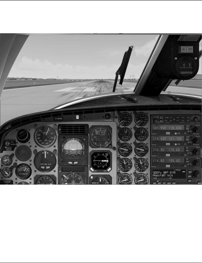
The Piper Cheyenne offers two ways to access the cockpit: A classic 2D cockpit view, and a 3D virtual cockpit view. By default, Microsoft Flightsimulator X will load the aircraft in 3D virtual cockpit view.
In classic 2D panel view, 5 different instrument panels are provided: Normal view, approach view, landing view, IFR view, VFR view and copilot view. In addition, Microsoft Flightsimulator X provides a Mini-panel view and a view mode where no panel is displayed. Cycling through this view is achieved using the W (forward) and SHIFT-W (backward) keys. Please note that it is not possible to use a joystick´s coolie hat to access the panel views in 2D mode.
Page 22 |
For flight simulation use only |
Aircraft Operation Manual
Piper Cheyenne I, IA, II, IIXL
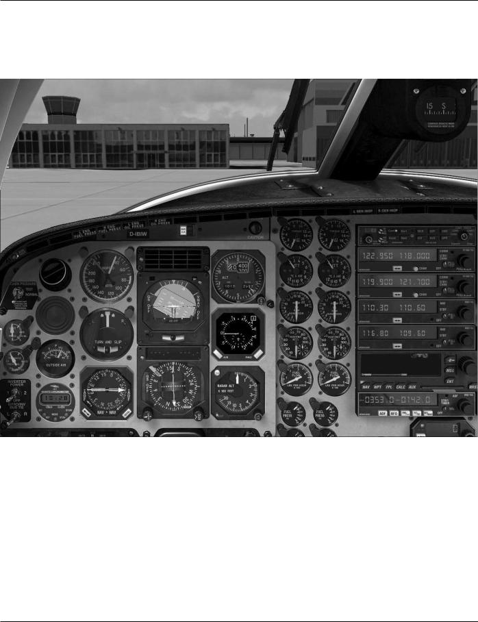
INSTRUMENT PANELS - Views
Normal view:
For flight simulation use only |
Page 23 |
Aircraft Operation Manual
Piper Cheyenne I, IA, II, IIXL
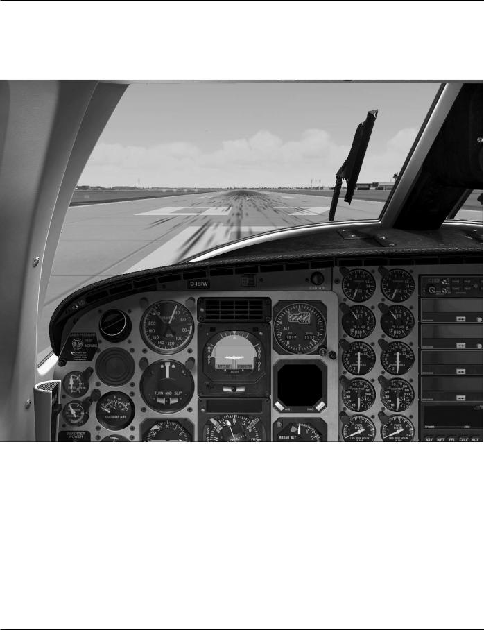
IFR view:
Page 24 |
For flight simulation use only |
Aircraft Operation Manual
Piper Cheyenne I, IA, II, IIXL
Approach/Landing view:
For flight simulation use only |
Page 25 |
Aircraft Operation Manual
Piper Cheyenne I, IA, II, IIXL
VFR view:
Page 26 |
For flight simulation use only |
Aircraft Operation Manual
Piper Cheyenne I, IA, II, IIXL
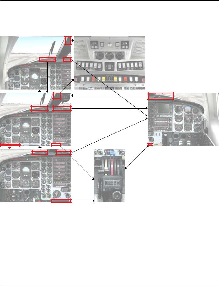
INSTRUMENT PANELS - Panel navigation by clickspots:
From the 2D cocpit, several sub-panels or view options may be selected by hidden clickspots and hotkeys. In summary, the following views and sub-panels are
available: |
|
• Normal view - Captain |
• Normal view - Copilot |
• IFR view - Captain |
• ADI/HSI zoomed - Captain |
• Landing view - Captain |
• Yoke visible |
• VFR view - Captain |
• Fuel selectors |
• Overhead-Panel |
• Kneeboard |
• Center pedestal |
• Map view |
• Radios |
• Microsoft ATC window |
For flight simulation use only |
Page 27 |

Aircraft Operation Manual
Piper Cheyenne I, IA, II, IIXL
In addition to these clickspots, panel view may also be selected by hotkeys:
• SHIFT-2: Overhead panel |
• SHIFT-6: Right radio stack |
• SHIFT-3: Center pedestal |
• SHIFT-7: Configuration screen |
• SHIFT-4: Fuel crossfeed panel |
• SHIFT-8: Autopilot zoom |
• SHIFT-5: ADI/HSI zoom |
• SHIFT-9: VOR2 & Alt preselect |
Sub-panels can be closed by clicking in the upper-right corner of the background bitmap.
The following additional hidden clickspots are available:
•ADI: Zooms the ADI and HSI
•Trimble GPS glass display: opens the map view window
•Area between radio stack and Glareshield: Displays the right radio stack
•Registration plate: Opens the kneeboard
•Fuel Flow gauges: Fuel selector window
•Microphone (Copilot view): Microsoft Flight Simulator ATC window
•Yoke shaft: Displays or hides the yoke
•Altitude preselector: Display the NAV2 gauge
Page 28 |
For flight simulation use only |

Aircraft Operation Manual
Piper Cheyenne I, IA, II, IIXL
INSTRUMENT PANELS - Overview
Pilot Panel
|
|
40 |
39 |
38 |
15 |
23 |
|
41 |
|
|
|
||||
|
|
37 |
|
16 |
24 |
|
|
|
|
6 |
3 |
|
|||
|
|
|
|
||||
11 |
|
|
|
|
|
||
42 |
|
1 |
|
17 |
|
|
|
|
|
|
25 |
|
|||
12 |
|
|
|
|
|
||
|
7 |
|
4 |
|
|
||
|
|
18 |
|
|
|||
13 |
9 |
|
|
|
|
|
|
|
|
|
19 |
26 |
|
||
|
|
8 |
2 |
5 |
|
|
|
14 |
10 |
|
27 |
|
|||
|
|
|
20 |
|
|||
|
|
|
|
|
28 |
||
|
|
|
|
|
21 |
||
|
|
|
34 |
|
|
|
|
|
|
|
35 |
|
29 |
|
|
|
|
31 |
|
22 |
30 |
||
|
|
|
|
||||
|
|
32 33 32 |
36 |
43 |
|
|
|
|
|
|
|
|
|
|
|
1: Attitude Direction Indicator |
15: Engine Torque |
|
29: KM551 VOR Indicator |
|
|||
2: Horizontal Situation Indicator |
16: ITT Gauge |
|
|
30: Flap Control & Position |
|
||
3: Altimeter |
|
17: Propeller RPM |
|
31: Pressurization Controller |
|||
4: Vertical Speed Indicator & TCAS |
18: Gas Generator RPM |
|
32: H.T.G. Switches |
|
|||
5: Radar Altimeter |
|
19: Fuel Flow |
|
|
33: Parking Brake |
|
|
6: True Airspeed Indicator |
20: Fuel Pressure |
|
34: Yoke shaft (click toggles yoke) |
||||
7: Turn & Bank Indicator |
21: Oil Pressure |
|
35: Gear Lever & Indicators |
|
|||
8: KNI 582 RMI |
|
22: Oil Temperature |
|
36: Oxygen Control |
|
||
9: OAT Indicator |
|
23: KMA 28 Audio Panel |
|
37: KAP 285 Mode Annunciator |
|||
10: Clock |
|
|
24: KY 196A COM1/2 Radios |
|
38: Master Caution Light |
|
|
11: Cabin Pressure Test Switch |
25: KN 53 NAV1/2 Radios |
|
39: Nav/GPS Switch |
|
|||
12: Gyro Pressure |
|
26: Trimble 2000 GPS |
|
40: Annunciator Display |
|
||
13: Pneumatic Pressure |
27: KR 87 ADF Radio 1 |
|
41: Annunciator Test Switch |
||||
14: Inverter & Bus Tie Switches |
28: KAS 297 Altitude Preselector |
42: SAS system (Cheyenne II only) |
|||||
|
|
|
|
|
|
43: Propeller Synchronizer |
|
For flight simulation use only |
Page 29 |
Aircraft Operation Manual
Piper Cheyenne I, IA, II, IIXL
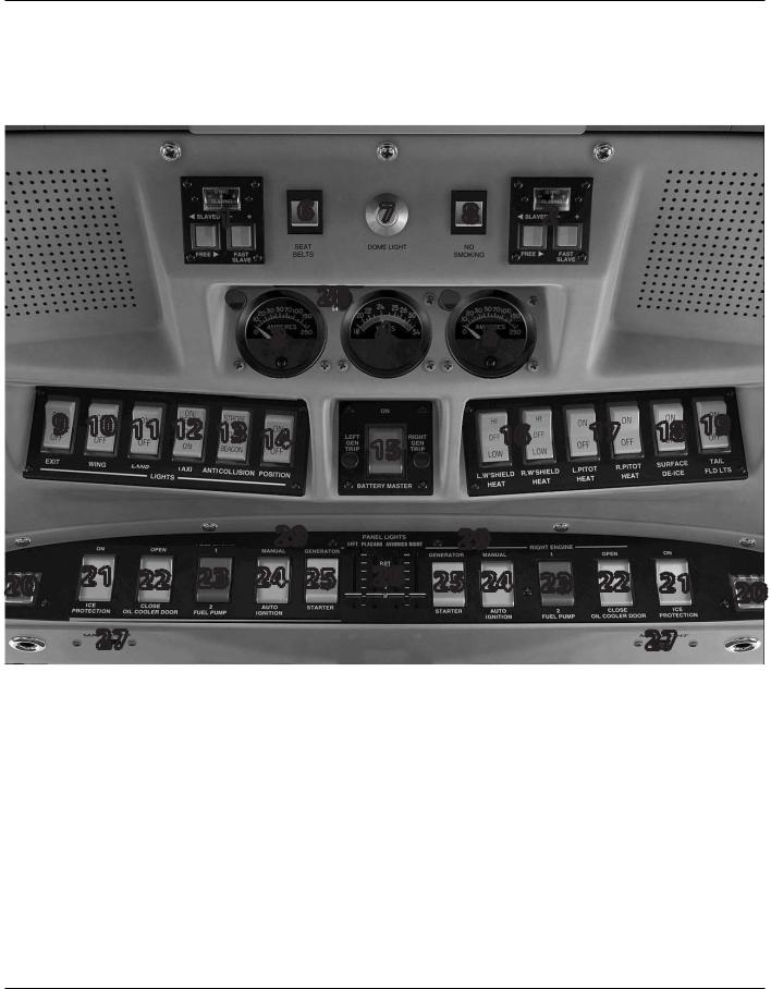
Overhead-Panel (Cheyenne I, IA and II)
|
|
|
1 |
|
6 |
7 |
8 |
|
2 |
|
|
|
|
|
|
|
|
28 |
|
|
|
|
|
|
|
|
|
|
|
3 |
|
4 |
|
5 |
|
|
|
|
9 |
10 11 12 13 14 |
|
15 |
|
16 |
17 |
18 19 |
|
||||
|
|
|
|
|
|
|
|
|
|
|
|
|
|
|
|
|
29 |
|
29 |
|
|
|
|
||
20 |
21 |
22 |
23 |
24 |
25 |
26 |
25 24 |
23 |
22 |
21 |
20 |
|
|
27 |
|
|
|
|
|
|
|
|
|
27 |
|
1: Left gyro controls |
|
15: Battery Master Switch |
|
connect external power from the |
||||||||
2: Right gyro controls |
|
16: Windshield Heat Switches |
|
external/auxiliary power unit (APU) |
||||||||
3: Left Generator Ammeter |
|
17: Pitot Heat Switches |
|
|
29: Starter Disengage Buttons |
|
||||||
4: Voltmeter |
|
|
18: Surface Deice Switch |
|
(Cheyenne IA only) |
|
||||||
5: Right Generator Ammeter |
19: Tail Floodlights Switch |
|
|
|
|
|
||||||
6: Seat Belts Switch |
|
|
20: Fire Extinguishers |
|
|
|
|
|
|
|||
7: Dome Light |
|
|
21: Deicing System Switches |
|
|
|
|
|
||||
8: No Smoking Switch |
|
22: Oil Cooler Door Switches |
|
|
|
|
|
|||||
9: Exit Lights Switch |
|
23: Fuel Pump Switches |
|
|
|
|
|
|
||||
10: Wing Lights Switch |
|
24: Ignition Switches |
|
|
|
|
|
|
||||
11: Landing Lights Switch |
|
25: Engine Starters and Generators |
|
|
|
|
||||||
12: Taxi Lights Switch |
|
26: Panel Light Switches |
|
|
|
|
|
|
||||
13: Anti-Collision Lights Switch |
27: Map Light Switches |
|
|
|
|
|
|
|||||
14: Position Lights Switch |
|
28: ELT Switch. Connect or dis- |
|
|
|
|
|
|||||
Page 30 |
For flight simulation use only |
 Loading...