


AIRBUS A320/A321
Volume 4
Systems Guide
Version 01-03-001
RECORD OF REVISIONS
revision n° |
Issue date |
Release |
Description |
|
|
|
|
001 |
Oct 30, 2104 |
1.00 |
completion |
|
|
|
|
|
|
|
|
|
|
|
|
|
|
|
|
|
|
|
|
|
|
|
|
|
|
|
|
|
|
|
|
|
|
|
|
|
|
|
|
|
|
|
|
|
|
|
|
|
|
|
|
|
|
|
|
|
|
|
|
|
|
|
|
|
|
|
|
|
|
|
|
|
|
|
|
|
|
|
|
|
|
|
|

Aerosoft |
|
SYSTEMS |
Vol |
04-03-2 |
Airbus A320/A321 |
|
Systems guide |
4 |
28 October 2014 |
CONTENTS |
|
|
|
|
INTRODUCTION ........................................................................................................................................................... |
|
|
5 |
|
AIRCRAFT GENERAL ..................................................................................................................................................... |
|
|
5 |
|
AIR CONDITIONING & PNEUMATICS ........................................................................................................................... |
|
|
5 |
|
PRESSURIZATION..................................................................................................................................................... |
|
|
7 |
|
VENTILATION........................................................................................................................................................... |
|
|
8 |
|
APU .............................................................................................................................................................................. |
|
|
8 |
|
GENERAL.................................................................................................................................................................. |
|
|
8 |
|
SYSTEM COMPONENTS ........................................................................................................................................... |
|
|
8 |
|
AIR BLEED SYSTEM .................................................................................................................................................. |
|
|
8 |
|
CONTROLS AND DISPLAYS....................................................................................................................................... |
|
|
8 |
|
AUTOFLIGHT ................................................................................................................................................................ |
|
|
9 |
|
OVERVIEW............................................................................................................................................................... |
|
|
9 |
|
PILOT INTERFACES................................................................................................................................................... |
|
|
9 |
|
FLIGHT CONTROL UNIT ....................................................................................................................................... |
|
|
9 |
|
MULTIFUNCTION CONTROL AND DISPLAY UNIT............................................................................................... |
|
10 |
||
SIDESTICK CONTROLLER.................................................................................................................................... |
|
|
10 |
|
THRUST LEVERS................................................................................................................................................. |
|
|
11 |
|
FLIGHT PHASES...................................................................................................................................................... |
|
|
11 |
|
PERFORMANCE...................................................................................................................................................... |
|
|
11 |
|
AUTOPILOTS .......................................................................................................................................................... |
|
|
12 |
|
ENGAGEMENT................................................................................................................................................... |
|
|
12 |
|
DISENGAGEMENT ............................................................................................................................................. |
|
|
12 |
|
AUTOPILOT & SPEED BRAKES ........................................................................................................................... |
|
|
12 |
|
AUTOTHRUST ........................................................................................................................................................ |
|
|
12 |
|
AUTOTHRUST ARMING STATUS........................................................................................................................ |
|
|
13 |
|
AUTOTHRUST ACTIVE STATUS .......................................................................................................................... |
|
|
13 |
|
AUTOTHRUST DEACTIVATION........................................................................................................................... |
|
|
13 |
|
AUTOTHRUST MODES....................................................................................................................................... |
|
|
13 |
|
AUTOTHRUST/FLIGHT DIRECTOR/AUTOPILOT.................................................................................................. |
|
13 |
||
ALPHA FLOOR.................................................................................................................................................... |
|
|
14 |
|
FLIGHT AUGMENTATION COMPUTERS ................................................................................................................. |
|
|
14 |
|
FLIGHT ENVELOPE ............................................................................................................................................. |
|
|
14 |
|
WINDSHEAR ...................................................................................................................................................... |
|
|
14 |
|
LOW ENERGY WARNING ................................................................................................................................... |
|
|
14 |
|
FLIGHT GUIDANCE................................................................................................................................................. |
|
|
14 |
|
LATERAL GUIDANCE MODES ................................................................................................................................. |
|
|
15 |
|
SELECTED HEADING (OR TRACK) MODE ........................................................................................................... |
|
|
15 |
|
MANAGED NAVIGATION MODE........................................................................................................................ |
|
|
15 |
|
LOCALIZER LATERAL MODE............................................................................................................................... |
|
|
15 |
|
VERTICAL MODES .................................................................................................................................................. |
|
|
16 |
|
CLIMB................................................................................................................................................................ |
|
|
16 |
|
OPEN CLIMB...................................................................................................................................................... |
|
|
17 |
|
DESCENT................................................................................................................................................................ |
|
|
17 |
|
OPEN DESCENT ................................................................................................................................................. |
|
|
19 |
|
ALTITUDE ACQUIRE........................................................................................................................................... |
|
|
19 |
|
ALTITUDE HOLD ................................................................................................................................................ |
|
|
19 |
|
VERTICAL SPEED – FLIGHT PATH ANGLE ........................................................................................................... |
|
|
20 |
|
COMMON MODES................................................................................................................................................. |
|
|
21 |
|
TAKE OFF: SRS ................................................................................................................................................... |
|
|
21 |
|
TAKE OFF: RUNWAY.......................................................................................................................................... |
|
|
21 |
|
APPROACH: ILS APPROACH............................................................................................................................... |
|
|
22 |
|
APPROACH: NON ILS APPROACH ...................................................................................................................... |
|
|
23 |
|
GO AROUND...................................................................................................................................................... |
|
|
24 |
|
MANAGES MODE VERSUS SELECTED MODE ......................................................................................................... |
|
|
25 |
|
MANAGED SPEED.............................................................................................................................................. |
|
|
25 |
|
Aerosoft |
|
SYSTEMS |
Vol |
04-03-3 |
Airbus A320/A321 |
|
Systems guide |
4 |
28 October 2014 |
SELECTED SPEED ............................................................................................................................................... |
|
|
25 |
|
MANAGED LATERAL GUIDANCE........................................................................................................................ |
|
|
26 |
|
SELECTED LATERAL GUIDANCE HEADING OR TRACK ........................................................................................ |
|
26 |
||
MANAGED CLIMB.............................................................................................................................................. |
|
|
27 |
|
OPEN CLIMB...................................................................................................................................................... |
|
|
27 |
|
SELECTED CLIMB ............................................................................................................................................... |
|
|
28 |
|
MANAGED DESCENT ......................................................................................................................................... |
|
|
28 |
|
OPEN DESCENT ................................................................................................................................................. |
|
|
29 |
|
SELECTED DESCENT........................................................................................................................................... |
|
|
29 |
|
VERTICAL GUIDANCE LEVEL OFF ....................................................................................................................... |
|
|
30 |
|
COMMUNICATIONS ................................................................................................................................................... |
|
|
31 |
|
COMMUNICATION RADIOS ................................................................................................................................... |
|
|
31 |
|
AUDIO MANAGEMENT SYSTEM ............................................................................................................................ |
|
|
32 |
|
DOORS AND WINDOWS............................................................................................................................................. |
|
|
32 |
|
ELECTRICAL ................................................................................................................................................................ |
|
|
33 |
|
GENERAL ........................................................................................................................................................... |
|
|
33 |
|
AC GENERATION ............................................................................................................................................... |
|
|
33 |
|
AC BUSES........................................................................................................................................................... |
|
|
33 |
|
DC GENERATION ............................................................................................................................................... |
|
|
33 |
|
PRIORITY LOGIC................................................................................................................................................. |
|
|
34 |
|
GROUND POWER .............................................................................................................................................. |
|
|
34 |
|
ECAM ELEC SYSTEM DISPLAYS .......................................................................................................................... |
|
|
34 |
|
ELEC OVERHEAD PANEL .................................................................................................................................... |
|
|
35 |
|
EQUIPMENT............................................................................................................................................................... |
|
|
36 |
|
FLIGHT CONTROLS ..................................................................................................................................................... |
|
|
36 |
|
GENERAL................................................................................................................................................................ |
|
|
36 |
|
COCKPIT CONTROLS .............................................................................................................................................. |
|
|
36 |
|
COMPUTERS .......................................................................................................................................................... |
|
|
36 |
|
PITCH CONTROL .................................................................................................................................................... |
|
|
37 |
|
ROLL CONTROL...................................................................................................................................................... |
|
|
37 |
|
YAW CONTROL ...................................................................................................................................................... |
|
|
37 |
|
FLARE MODE ......................................................................................................................................................... |
|
|
37 |
|
SPEED BRAKES AND GROUND SPOILER CONTROL ................................................................................................ |
|
37 |
||
OVERHEAD PANEL CONTROLS............................................................................................................................... |
|
|
37 |
|
ECAM F/CTL & WHEEL PAGE ................................................................................................................................. |
|
|
38 |
|
PROTECTIONS........................................................................................................................................................ |
|
|
38 |
|
FLAPS AND SLATS .................................................................................................................................................. |
|
|
39 |
|
FLIGHT INSTRUMENTS ............................................................................................................................................... |
|
|
40 |
|
ELECTRONIC FLIGHT INSTRUMENT SYSTEM.......................................................................................................... |
|
|
40 |
|
EFIS CONTROL PANEL........................................................................................................................................ |
|
|
41 |
|
ELECTRONIC CENTRALIZED AIRCRAFT MONITOR.................................................................................................. |
|
41 |
||
ECAM CONTROL PANEL .................................................................................................................................... |
|
|
42 |
|
STANDBY COMPASS .............................................................................................................................................. |
|
|
42 |
|
STANDBY HORIZON ............................................................................................................................................... |
|
|
42 |
|
DDRMI ................................................................................................................................................................... |
|
|
42 |
|
CLOCK .................................................................................................................................................................... |
|
|
42 |
|
VOR/DME RECEIVERS ............................................................................................................................................ |
|
|
43 |
|
FLIGHT MODE ANNUNCIATOR .............................................................................................................................. |
|
|
43 |
|
AUTO THRUST OPERATIONS ANNUNCIATIONS ................................................................................................ |
|
43 |
||
AP/FD VERTICAL MODE ANNUNCIATIONS........................................................................................................ |
|
|
44 |
|
AP/FD A/THR ENGAGEMENT ANNUNCIATIONS ............................................................................................... |
|
44 |
||
APROACH CAPABILITIES ANNUNCIATIONS ....................................................................................................... |
|
|
45 |
|
APPROACH CAPABILITIES ANNUNCIATIONS ..................................................................................................... |
|
|
45 |
|
FUEL ........................................................................................................................................................................... |
|
|
47 |
|
GENERAL ........................................................................................................................................................... |
|
|
47 |
|
TANKS................................................................................................................................................................ |
|
|
47 |
|
ENGINE FEED..................................................................................................................................................... |
|
|
47 |
|
Aerosoft |
|
SYSTEMS |
Vol |
04-03-4 |
Airbus A320/A321 |
|
Systems guide |
4 |
28 October 2014 |
FUEL FEED SEQUENCE....................................................................................................................................... |
|
|
47 |
|
CENTRE FUEL TANK TRANSFER ......................................................................................................................... |
|
|
48 |
|
OVERHEAD PANEL............................................................................................................................................. |
|
|
48 |
|
ECAM FUEL SYSTEM DISPLAY............................................................................................................................ |
|
|
49 |
|
HYDRAULIC SYSTEM................................................................................................................................................... |
|
|
50 |
|
GENERAL................................................................................................................................................................ |
|
|
50 |
|
ECAM HYD PAGE ................................................................................................................................................... |
|
|
50 |
|
HYD OVERHEAD PANEL ......................................................................................................................................... |
|
|
50 |
|
ICE AND RAIN PROTECTION ....................................................................................................................................... |
|
|
51 |
|
WING ANTI-ICE PROTECTION SYSTEM .................................................................................................................. |
|
|
51 |
|
PROBE / WINDOW ANTI-ICE PROTECTION SYSTEM .............................................................................................. |
|
51 |
||
ENGINE ANTI-ICE PROTECTION SYSTEM................................................................................................................ |
|
|
52 |
|
RAIN REMOVAL ..................................................................................................................................................... |
|
|
52 |
|
LANDING GEAR AND BRAKES..................................................................................................................................... |
|
|
52 |
|
GENERAL................................................................................................................................................................ |
|
|
52 |
|
NOSEWHEEL STEERING ......................................................................................................................................... |
|
|
53 |
|
MAIN WHEEL BRAKES............................................................................................................................................ |
|
|
53 |
|
ANTI-SKID .............................................................................................................................................................. |
|
|
53 |
|
AUTOBRAKES......................................................................................................................................................... |
|
|
53 |
|
BRAKE-FAN ............................................................................................................................................................ |
|
|
53 |
|
LANDING GEAR LEVER AND INDICATOR PANEL .................................................................................................... |
|
|
53 |
|
ECAM WHEEL PAGE............................................................................................................................................... |
|
|
53 |
|
ACCU-PRESS/BRAKE GAUGE.................................................................................................................................. |
|
|
54 |
|
PARKING BRAKE .................................................................................................................................................... |
|
|
54 |
|
LIGHTING ................................................................................................................................................................... |
|
|
54 |
|
COCKPIT LIGHTING ................................................................................................................................................ |
|
|
54 |
|
EXTERNAL LIGHTS.................................................................................................................................................. |
|
|
54 |
|
MASTER CAUTION, MASTER WARNING & AUTOLAND WARNING ............................................................................ |
|
55 |
||
NAVIGATION .............................................................................................................................................................. |
|
|
55 |
|
ADIRS..................................................................................................................................................................... |
|
|
55 |
|
RADIO NAVIGATION .............................................................................................................................................. |
|
|
55 |
|
NAVIGATION RADIOS........................................................................................................................................ |
|
|
56 |
|
GPWS..................................................................................................................................................................... |
|
|
56 |
|
RUNWAY AWARENESS AND ADVISORY SYSTEM ................................................................................................... |
|
56 |
||
RADIO ALTIMETER / TCAS ..................................................................................................................................... |
|
|
57 |
|
POWER PLANT ........................................................................................................................................................... |
|
|
58 |
|
FADEC .................................................................................................................................................................... |
|
|
58 |
|
THRUST CONTROL SYSTEM ................................................................................................................................... |
|
|
58 |
|
THRUST LEVERS ..................................................................................................................................................... |
|
|
58 |
|
MANUAL MODE..................................................................................................................................................... |
|
|
59 |
|
RADIO NAVIGATION................................................................................................................................................... |
|
|
59 |
|
NAVAID SELECTION ON MCDU PAGES .................................................................................................................. |
|
|
59 |
|
AUTOTUNE VOR .................................................................................................................................................... |
|
|
59 |
|
AUTOTUNE ADF/DME ........................................................................................................................................... |
|
|
59 |
|
AUTOTUNE ILS....................................................................................................................................................... |
|
|
59 |
|
SEATBELT/NO SMOKING............................................................................................................................................ |
|
|
60 |
|
WEATHER RADAR ...................................................................................................................................................... |
|
|
60 |
|
AUTO MULTISCAN MODE...................................................................................................................................... |
|
|
60 |
|
MAN MULTISCAN MODE....................................................................................................................................... |
|
|
60 |
|
CONTROLS ............................................................................................................................................................. |
|
|
63 |
|
WEATHER RADAR DISPLAY.................................................................................................................................... |
|
|
63 |
|
OPERATION ........................................................................................................................................................... |
|
|
63 |
|
GLOSSARY .................................................................................................................................................................. |
|
|
65 |
|
Aerosoft |
SYSTEMS |
Vol |
04-03-5 |
Airbus A320/A321 |
Systems guide |
4 |
28 October 2014 |
INTRODUCTION
It is very easy to find actual manuals for the A320 range of aircraft on the internet. For obvious reasons we cannot include them but even a quick source will lead you to a treasure-trove of information. Start your search with ‘A320 FCOM’ to find complete operation manuals. Almost all you find in there is applicable to this product.
AIRCRAFT GENERAL
The Airbus A320 family includes the A318, A319, A320, and A321, all medium range, subsonic narrow body civil aviation aircraft. Powered by two high-powered by-pass turbofan engines they seat up to 220 passengers.
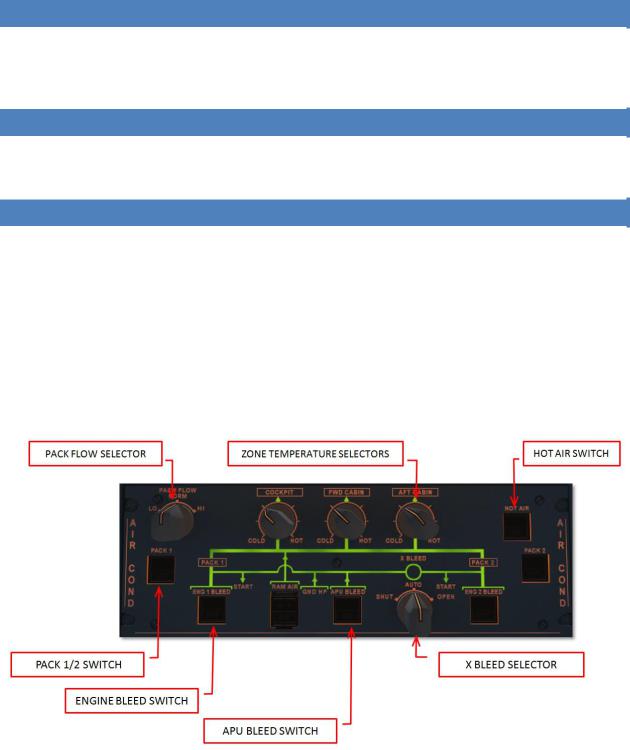
AIR CONDITIONING & PNEUMATICS
The air conditioning system is fully automatic and provides continuous renewal of conditioned air in three zones: COCKPIT, FWD CABIN and AFT CABIN. Temperatures in these three zones can be regulated independently. The air is supplied via the pneumatic systems using:
two pack flow control valves
two packs
the mixing unit that combines air from the packs and the cabin
The cold air from the PACKs is mixed with the hot bleed air (taken from the engines or APU) by a mixing unit that is controlled by the zone regulator.
All control is done via the AIR COND panel on the overhead panel.
Zone temperature control selectors o COLD = 18 °C
o CENTER = 24 °C o HOT = 30° C
HOT AIR pb switch
o ON: hot air pressure is regulated
Aerosoft |
SYSTEMS |
Vol |
04-03-6 |
Airbus A320/A321 |
Systems guide |
4 |
28 October 2014 |
oOFF: valve closes + trim air valve closes and cabin temperature will drop to external temperature
oFAULT: (plus ECAM caution) when duct temperature is above 80°C, resets when temperature is below 70°C
PACK pb switch
oON: pack flow control is automatically controlled (note the pack flow valve is closed during
certain conditions like engine start etc.) o OFF: pack flow control valves close
oFAULT: (plus ECAM caution) when valve position does not match the selected position
PACK FLOW
oLO: to be used with little or no passengers
o NORM: to be used with (near to) maximum amount of passengers
oHI: to be used to clear smoke or contaminants or in extreme temperatures (only available if both engines are running)
ENG x BLEED pb
oON
o OFF o FAULT
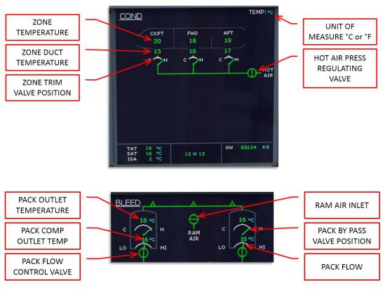
Feedback on the air conditioning system is given on the ECAM COND page and on the ECAM BLEED page.

|
|
Aerosoft |
SYSTEMS |
Vol |
04-03-7 |
|
|
Airbus A320/A321 |
Systems guide |
4 |
28 October 2014 |
|
|
|
|
|
|
PRESSURIZATION
Under normal operation conditions the complete pressurization is fully automatic. The system consists of:
two Cabin Pressure Controllers
outflow valve
control panel
two safety valves
In automatic operation pressurization is divided in 6 different modes
Ground: before take-off and 1 minute after landing the outflow valve is fully open to equalize pressure with outside pressure.
Take-off: just before take-off the system prepresurizes the cabin to avoid a sudden pressure increase
Climb: cabin altitude is decreased to cruise level using input from vertical speed and other sensors
Cruise: cabin pressure is maintained
Descent: cabin altitude is increased to cruise level using input from vertical speed and other sensors
Abort: in case of an aborted take-off the system will prevent the triggered climb mode from starting to decrease the pressure.

|
|
Aerosoft |
SYSTEMS |
Vol |
04-03-8 |
|
|
Airbus A320/A321 |
Systems guide |
4 |
28 October 2014 |
|
|
|
|
|
|
VENTILATION
The ventilation of avionics is controlled by the Avionics Equipment Ventilation Controller (AEVC). It provides cooling of the avionics compartments using two fans, a heat exchanger that uses the outside skin of the aircraft to cool the air and an inlet and outlet valve. Only the automated mode is simulated and you can see the ventilation valve position on the CAB PRESS ECAM page. Battery, galley and toilet ventilation is provided by fans that draws air from the cabin and vents it overboard via a vent in the aircraft skin.
Do note that the AEVC is very loud and other sounds from the aircraft systems that are heard on other aircraft types are not heard on the Airbus A320 series.
APU
GENERAL
The Auxiliary Power Unit provides:
Bleed air for engine starting
Bleed air for air conditioning
Electrical power for all the buses
The APU can be used on the ground and in flight with the following limitations:
100% generator load up to 25,000 feet
Full pneumatic and hydraulic pressure up to 20,000 feet
Can be started using the battery up to 25,000 feet.
SYSTEM COMPONENTS
The APU consists of a gas turbine engine with an APU computer that manages the system. The air intake uses a electrically operated inlet flap and the exhaust vents in the tail cone. The electrical starter will start the engine when the inlet flap is fully opened. The fuel is taken from the left wing tank using a separate fuel pump.
AIR BLEED SYSTEM
Bleed air from the APU is selectable from the overhead panel and has priority over main engine bleed air as long as the APU BLEED pb is ON. The bleed air can start engines and provide the air condition system.
CONTROLS AND DISPLAYS
The APU ECAM page displays the parameters of the APU. For the gas turbine engine N (in %) and EGT (in °C) are available. The APU generator shows load (in %), voltage (in V) and frequency (in HZ) plus the connection to the bus (arrow when connected, nothing when not connected). Bleed air shows pressure (in PSI) plus the position of the valve (open or closed). All system messages are shown in green while within correct parameters, or amber when outside correct parameters.
The APU MASTER SW pb on the overhead APU panel is pressed (ON will show) to power up the APU computer, the fuel pump is activated and the air inlet is opened. When ON is shown the APU is ready to start.
The APU START pb starts the APU. When pressed it will show ON and the APU computer will command and control the startup. Aircraft batteries must be selected ON, even when the engine generators are online. When
Aerosoft |
SYSTEMS |
Vol |
04-03-9 |
Airbus A320/A321 |
Systems guide |
4 |
28 October 2014 |
the APU is running and bleed air and electrical power are available a green AVAIL will show and the ON will not be shown. Note the APU needs a 3 minute cool down period after it has shut down.
On the ELEC panel the APU GEN pb will be dark when the APU generator is ON, and when pressed it will show OFF as the APU generator is taken of line. When there is any problem an amber FAULT will show and the ECAM will show more information.
On the AIR COND panel the APU BLEED pb will show ON when APU N speed is sufficient. When pushed the pb will be dark and the bleed air valve will close. When there is any problem an amber FAULT will show and the ECAM will show more information.
AUTOFLIGHT
OVERVIEW
The following components are used by the pilot to interact with the autoflight system:
Flight Control Unit (FCU)
Multifunction Control and Display Units (MCDUs)
Sidesticks
Thrust levers
Primary Flight Display (PFD)
Navigation Display (ND)
The autoflight system is part of the Flight Management System (FMS). The FMS (including autopilots and autothrust system) is made up by two Flight Management Guidance Computers (FMGCs) and two Flight Augmentation Computers (FACs).
FACs |
|
FLIGHT MANAGEMENT |
|
FMS |
FLIGHT GUIDANCE |
||
FMGCs |
|||
|
FLIGHT AUGMENTATION |
||
|
|
Flight Management provides navigation, performance optimization and display management.
Flight Guidance provides autopilot commands (sent to the flight control computers), flight director commands (sent to the PFD) and thrust commands (sent to the autothrust systems).
Flight Augmentation provides flight envelope calculations, turn coordination and yaw damping.
PILOT INTERFACES
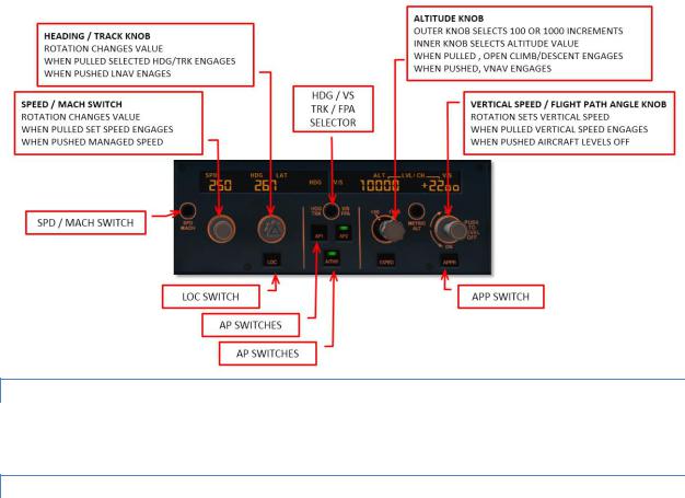
FLIGHT CONTROL UNIT
The FCU is located in the center of the glareshield and four knobs provide control for:
Airspeed
Heading (or track) or navigation modes
Climb or descent modes and/or
Vertical speed (or flight path angle)
Aerosoft |
SYSTEMS |
Vol |
04-03-10 |
Airbus A320/A321 |
Systems guide |
4 |
28 October 2014 |
There are two modes possible for airspeed, heading and vertical speed. Switching between modes is done by pulling (right click) the knob.
Selected Functions
oIn selected mode the pilot controls speed and lateral/vertical navigation. After pulling the knob the pilot can rotate the knob to set the desired value. When the knob is pushed (left click) the current value for that function is inserted.
Managed Functions
oIn managed mode the displays are dashed (note the FCU altitude windows is never dashed) and the control of speed and lateral/vertical navigation is managed by the FMS.
MULTIFUNCTION CONTROL AND DISPLAY UNIT
The MCDUs is the primary interface between pilot and FMS (and in our simulation it is also used to access some simulation functions.
SIDESTICK CONTROLLER
The sidestick controllers are used to fly the aircraft manually. Any strong input with these will deactivate the autopilot.
Aerosoft |
SYSTEMS |
Vol |
04-03-11 |
Airbus A320/A321 |
Systems guide |
4 |
28 October 2014 |
THRUST LEVERS
The thrust levers are used to manually control thrust or to select the desired autothrust mode. With both engines operating the autothrust range is between the idle and the FLX/MCT detents. With autothrust active the position of the thrust lever determines the maximum thrust level.
Normally the thrust levers are positioned in the climb (CL) detent at the thrust reduction altitude after takeoff and left there until the landing flare.
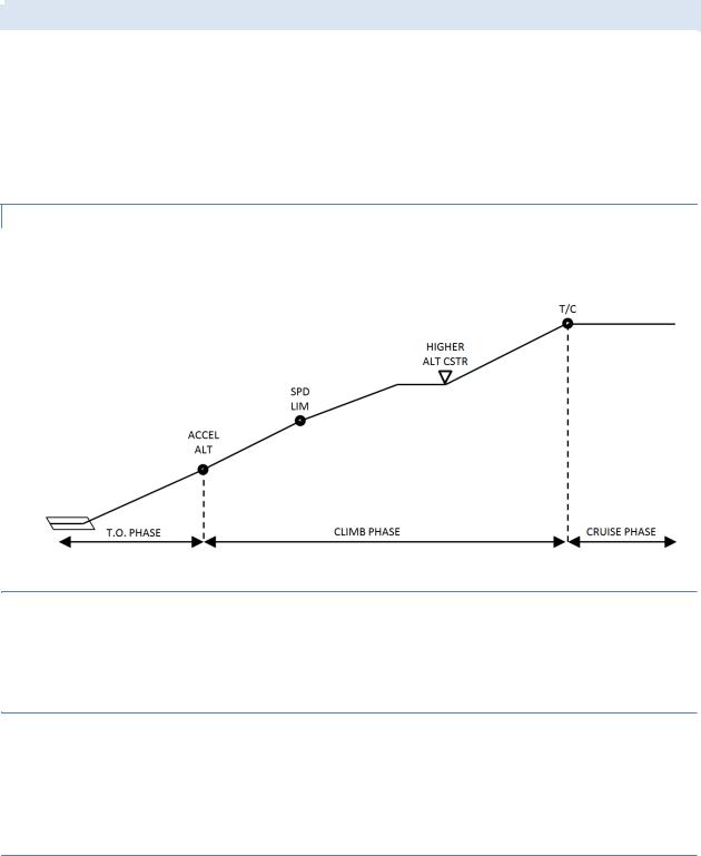
FLIGHT PHASES
The FMGC divides the complete flight into phases that normally will automatically switch to the next phase when certain conditions are met.
|
|
Flight Phase |
Optimum Speed Profile |
Switching conditions to next phase |
|
|
Preflight |
- |
SRS take off mode engaged + |
|
|
N1 > 85% or Ground Speed > 90 kts |
||
|
|
|
|
|
|
|
Take Off |
V2 followed by V2 +10 |
At ACC ALT (or manually) |
|
|
Climb |
ECON CLB SPD/MACH |
At reaching Cruise Flight Level |
|
|
Cruise |
ECON CRZ MACH |
At reaching ToD |
|
|
Descent |
ECON DES MACH/SPD |
Overflying Decel waypoint with NAV (or LOC/LOC*) engaged |
|
|
Manually activating APPR phase |
||
|
|
|
|
|
|
|
|
|
To Go Around: thrust levers to TOGA |
|
|
Approach |
VAPP (GS Min) |
To Done: automatic 30 seconds after landing |
|
|
|
|
To Climb: inserting new CRZ FL |
|
|
Go Around |
VAPP or Current Speed |
To Approach: manually select APPR phase |
|
|
To Climb: manually select CLMB phase |
||
|
|
|
|
|
|
|
Done |
|
At depressing INIT or PERF to Preflight |
|
|
|
|
|
PERFORMANCE
The FMGC will minimize the flight cost through speed optimization. Depending on the Cost Index setting it will compute optimal targets for the following items:
Take off, approach and go around speed are calculated as a function of the TOW and performance model. Note that V1, V2 and Vr have to be manually entered (in our aircraft these speeds are calculated but can be overwritten.
CLB and DES speeds are computed as a function of the GW, Cost Index, environment (temperature, wind) and Cruise level. The speeds are NOT recalculated when the mode is active.
Cruise Mach is computed as the optimal speed and is updated continuously update to the current weather condition and F-PLN modifications.
Optimum Flight Level is calculated assuming a 5 minute minimum cruise flight. It is continuously update in flight.

|
|
Aerosoft |
SYSTEMS |
Vol |
04-03-12 |
|
|
Airbus A320/A321 |
Systems guide |
4 |
28 October 2014 |
|
|
|
|
|
|
AUTOPILOTS
ENGAGEMENT
The autopilot (two identical systems) are engaged by the AP1 and AP2 pb on the FCU. When engaged a green bar will show on the pb and the appropriate FMA annunciation is displayed. When a flight director is on when the autopilot is engaged, the autopilot engages in appropriate mode (OP CLMB and NAV) otherwise it will engage in the default guidance modes (HDG and V/S or TRK-FPA).
Either autopilot can be engaged seconds after takeoff.
DISENGAGEMENT
Disengage the autopilot by depressing the AP1 or AP1 button.
The autopilot is automatically disengaged by moving the side stick (or rudder pedals) a certain amount. This will trigger a master warning.
The autopilot is automatically disengaged when the throttles are set above FLX/MCT on ground.
The autopilot is automatically disengaged when a normal law is exceeded or pitch or bank angle are excessive.
The autopilot is automatically disengaged during a non-precision approach when the aircraft reaches MDA minus 50 feet .
AUTOPILOT & SPEED BRAKES
With the autopilot engaged the speed brakes are limited to ½ deflection. When autopilot is engaged with speed brakes extended beyond ½ they will retract to ½. Note this will cause a sudden pitch up.
AUTOTHRUST
The autothrust system reduces workload for the pilot, provides additional comfort for the passengers and reduces fuel use. Two main modes are included:
Fixed Thrust Modes
oUses constant thrust; airspeed is controlled with pitch. Normally used for level changes when no specific vertical speed is required.
Variable Thrust Modes
oIn variable thrust mode the airspeed remains constant by changing the amount of thrust. Normally used for level flight or when a certain airspeed is required during level change.

Aerosoft |
SYSTEMS |
Vol |
04-03-13 |
Airbus A320/A321 |
Systems guide |
4 |
28 October 2014 |
AUTOTHRUST ARMING STATUS
When autothrust is OFF the thrust is controlled manually and corresponds to the position of the trust levers. When autothrust is ARMED and the thrust levers are moved into the A/THR active the autothrust status changes to ACTIVE. The status is shown on the FMA (blue indicates armed mode and white indicates active mode). Autothrust is automatically armed during takeoff when thrust levers are in the TOGA or FLX detent.
AUTOTHRUST ACTIVE STATUS
The autothrust system controls thrust only in active status. Both fixed (MCT, CLB, IDLE, THR) and variable thrust (SPEED, MACH) modes are available in active status.
AUTOTHRUST DEACTIVATION
The autothrust system can be disabled by depressing the FCU A/THR pb or by retarding the throttles to the idle detent. A single chime and a short amber master caution illumination alerts the pilot.
AUTOTHRUST MODES
 FIXED THRUST MODES
TOGO: Provides fixed maximum thrust and is only available when autothrust status is armed.
FLX: Flex thrust is used for reduced thrust takeoffs. Thrust is calculated using the assumed temperature as set in the MCDU.
MCT: Provides Maximum Continuous Thrust at the current ambient conditions.
CLB: Provides fixed thrust equal to the climb thrust rating at current ambient conditions.
IDLE: Provides fixed idle thrust.
Only available in active autothrust status. Note the thrust levers can be anywhere in the autothrust range!
THR: When the thrust is not TOGA, FLX, MCT or CLB the fixed thrust is called THR.
 VARIABLE THRUST MODES
SPEED: The autothrust system will provide variable thrust to maintain a set speed or a managed speed in level flight or when the aircraft follows a programmed flight path. Only available when autothrust is active.
MACH: Identical to speed mode but not available at low altitudes. The speed mode is automatically switched to Mach mode (and vice versa) at a preset altitude.
AUTOTHRUST/FLIGHT DIRECTOR/AUTOPILOT
The vertical guidance modes use pitch to maintain a target speed or a specific vertical path. If vertical guidance modes are used to control a target speed, autothrust uses a fixed thrust mode. If vertical guidance modes are

Aerosoft |
SYSTEMS |
Vol |
04-03-14 |
Airbus A320/A321 |
Systems guide |
4 |
28 October 2014 |
used to control a specific vertical path, autothrust uses variable thrust to maintain target speed. When manually flown in fixed autothrust mode the flight director’s pitch command bar indicates the pitch needed to fly the desired speed.
ALPHA FLOOR
The alpha floor protection assists the pilot in recovering from dangerous low speed and high angle of attack by automatically setting TOGA thrust when:
Excessive angle of attack (alpha)
Excessive high nose up attitude
Windshear is detected
When the alpha floor conditions are no longer detected the autothrust system will stay in TOGA lock until the pilot disables auto throttle. It is recommended the pilot moves the throttle to the TOGA detent before depressing the FCU A/THR pb to avoid a power surge. After that the pilot can pull the throttle to the CL indent and engage the autothrust.
FLIGHT AUGMENTATION COMPUTERS
The FACs handle:
Yaw damping and turn coordination
Rudder trim
Flight envelope and maneuvering speed computations
Alpha floor protection
Windshear detection
Low energy detection
FLIGHT ENVELOPE
Many different speeds are calculated by the FACs are used by the autoflight system. These speeds include the minimum safe speed, maximum speed and never exceed speed. They also calculate the alpha floor speed. Most of these speeds are shown on the PFD airspeed indicator.
WINDSHEAR
The FACs will try to detect windshear and will warn the pilot of this dangerous condition. Windshear detection is only active below 1300 feet AGL in configuration 1 or greater. When detected the flight director will show an optimal pitch attitude and the aural warning “WINDSHEAR” will be heard.
LOW ENERGY WARNING
Between 2000 and 100 feet AGL the FACs will detect a low energy state (based on airspeed, descent angle and angle of attack) and will warn the pilot with an aural “SPEED SPEED SPEED” warning. Normally this warning will precede an alpha floor condition.
FLIGHT GUIDANCE

Aerosoft |
SYSTEMS |
Vol |
04-03-15 |
Airbus A320/A321 |
Systems guide |
4 |
28 October 2014 |
Flight guidance is provided for speed control, lateral navigation and (limited in this project) vertical navigation. There are two types:
Selected Guidance: In this mode the aircraft will fly on autopilot using the settings on the FCU. You switch from managed mode to selected mode by pulling (right mouse click) the SPD, HDG and ALT knobs.
Managed Guidance: In this mode the airspeed is calculated by the FMS and differs per flight phase. The FMS also provides managed lateral and vertical flight plan guidance following the flight plan that has been inserted in the MCDU. The FCU will show dashes in managed guidance. You switch from selected guidance to managed mode by pushing (left mouse click) the SPD, HDG or ALT knobs.
Please note the FCU altitude window will never be dashed.
When the autopilot is engaged or the flight director is activated the Flight Mode Annunciator (FMA) (at the top of the PFD) will also display the activated settings.
LATERAL GUIDANCE MODES
The lateral guidance modes keep the aircraft course to its destination.
SELECTED HEADING (OR TRACK) MODE
The heading (or track) mode will guide the aircraft on a heading (HDG) or track (TRK) and is the default lateral mode. The pilot activates it by pulling (right mouse click) the HDG button on the FCU. A digital display of the heading (track) will be shown on the FCU and HDG will be displayed on the FMA. Note this mode cannot be activated when LAND mode is activated.
If the knob is turned to the desired HDG (TRK) and pulled the aircraft will make the shortest turn to the selected HDG (TRK)
If the HDG knob is pulled but not turned the current HDG (TRK) is selected.
If the HDG knob is pulled first and turned the aircraft will turn in the direction of the turn.
If the HDG knob is turned but not pulled the selected value is cleared after a period that depends on the flight mode.
MANAGED NAVIGATION MODE
When a flight plan is available and activated the managed nav mode will guide the aircraft along the path stored in the FMS. It is activated by the pilot by pushing (left mouse click) the FCU HDG knob. The display will show dashes and the FMA will display NAV.
LOCALIZER LATERAL MODE
When the FCU LOC pb is pushed the loc lateral guidance mode is armed and the FGS will only use the localizer signal for lateral guidance. In the FMA LOC will be displayed and the LOC pb will illuminate. It can be used to intercept and track a localizer while maintaining a selected altitude. Note that a ILS frequency must be tuned and TAKEOFF and GO-AROUND mode are not selected. To disarm press the LOC pb again.
|
|
Aerosoft |
SYSTEMS |
Vol |
04-03-16 |
|
|
Airbus A320/A321 |
Systems guide |
4 |
28 October 2014 |
|
|
|
|
|
|
VERTICAL MODES
The vertical guidance modes will make the aircraft change altitude. To leave a FCU selected altitude a dual action sequence is needed:
Turn the ALT selector to set the new altitude
Pull the ALT selector to select OPEN CLB/DES mode or Push the ALT selector to engage CLB/DES mode or
Select a target V/S and pull the V/S selector knob to engage V/S mode
CLIMB
CLB mode manages the vertical guidance towards the FCU selected altitude taking altitude and speed constraints into account.
 ARMING CONDITIONS
On ground or when TAKE OFF or GA modea are engaged as long as no other vertical modes are selected.
In flight when lateral NAV mode is engaged, FCU selected altitude is higher than aircraft altitude or when aircraft meets a ALT CSTR
 DISARMING CONDITIONS
Engagement of any other vertical mode
FCU selected mode lower then aircraft altitude
Switching to DES or APP phase
Loss of vertical flight path validity or loss of ANV mode
 ENGAGEMENT CONDITIONS
Aircraft more than 5 seconds in flight
FCU selected altitude above current altitude
Not in descent or approach mode
NAV mode engaged
Not in G/S mode
CLB mode is automatically selected when

Aerosoft |
SYSTEMS |
Vol |
04-03-17 |
Airbus A320/A321 |
Systems guide |
4 |
28 October 2014 |
o ACC ALT is reached
oALT CSTR is reached with CLB mode armed
CLB mode can be manually selected by pushing the ALT selector knob.
 DISENGAGEMENT CONDITIONS
NAV mode lost or disengaged
Selecting another vertical mode
Setting a lower altitude in FCU than current altitude
 GUIDANCE
In standard CLB mode the engine stay at max climb thrust, the speed will be the one calculated by the FMGS and pitch will vary to keep that speed.
OPEN CLIMB
 ENGAGEMENT CONDITIONS
The aircraft must be in flight more than 5 seconds
LAND mode is not engaged
FCU selected altitude is higher than current altitude OPEN CLIMB is engaged by:
Pulling the ALT selector knob
Acceleration altitude reached with armed CLM mode and NAV not engaged
When an overspeed condition is detected (the aircraft will pitch up to loose speed)
 DISENGAGEMENT CONDITIONS
Selecting any other vertical mode
Selecting a lower altitude then the current altitude
 GUIDANCE
In OPEN CLB the target Speed / Mach is kept by varying the pitch, thrust is managed by the A / THR or manually, speed target can be selected or managed. All ALT CSTR are ignored in OPEN CLB.
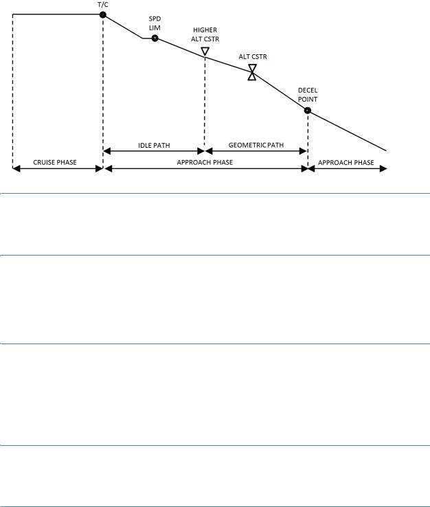
DESCENT
DES mode provides vertical guidance following a computed descent profile between Top of Descent to the Deceleration point. It uses the data in the F-PLN and the available WIND data. It is divided into three sections:
Repressurization segment (ignored in our simulation)
Idle Path segment where the engines are at idle and AP / FD controls SPD
Geometric path when the AP / FD controls vertical path and the A /THR controls the SPD
Aerosoft |
SYSTEMS |
Vol |
04-03-18 |
Airbus A320/A321 |
Systems guide |
4 |
28 October 2014 |
 ARMING CONDITIONS
FCU selected altitude is below current altitude
TAKE OFF, GO AROUND or LAND mode is not engaged
 DISARMING CONDITIONS
Selecting any other vertical mode
FCU selected altitude is above current altitude
Loss of NAV, LOC or vertical path validity
Selecting GO AROUND mode
 ENGAGEMENT CONDITIONS
FCU selected level is below current altitude
NAV, LOC* or LOC is active
TAKE OFF, GO AROUND, LAND, FINAL not active
DES mode is engaged automatically when an altitude constraint is met with DES mode armed.
DES mode is manually engaged by pushing the ALT selector knob
 DISENGAGEMENT CONDITIONS
Engagement of any other vertical mode
Selecting a FCU altitude above current altitude
 GUIDANCE
In DES mode the aircraft is guided along the DES PATH. The SPD target can be selected or managed (with the speed to vary around the calculated optimal nominal descent speed. SPD CSTR is taken into account in the speed profile.
If the aircraft is above the DES PATH it will pitch down until the upper limit of the MANAGED SPD RANGE is reached. That speed will be kept and the aircraft will differentiate from the DES PATH. Extending ½ speed brakes will allow the aircraft to get back on the calculated path.
If the aircraft is below the DES PATH the aircraft will maintain the target speed until the DES PATH is reached.

Aerosoft |
SYSTEMS |
Vol |
04-03-19 |
Airbus A320/A321 |
Systems guide |
4 |
28 October 2014 |
OPEN DESCENT
In selected descend mode the autothrust system will be set to idle and the set speed will be kept using pitch. This mode is not useful for final approaches.
 ENGAGEMENT CONDITIONS
The aircraft must be in flight more than 5 seconds
LAND mode is not engaged
FCU selected altitude is lower than current altitude
OPEN DESCENT is engaged by pulling the ALT selector knob
 DISENGAGEMENT CONDITIONS
Selecting any other vertical mode
Selecting a higher altitude then the current altitude
 GUIDANCE
In OPEN DES the target Speed / Mach is maintained by pitch controls and thrust is maintained by the A / THR or manually by the pilot. Speed target can be selected or managed.
ALTITUDE ACQUIRE
ALT* will guide the aircraft to the FCU selected altitude, ALT CST* guides the aircraft to an altitude constraint. Once the set altitude is reached the ALTITUDE HOLD (ALT or ALT CST) mode will engage.
 GUIDANCE
In the ALT* and ALT CST* mode the vertical speed is managed to reduce vertical speed to ensure a smooth capture of the set FCU altitude.
ALTITUDE HOLD
ALT mode will keep the aircraft at a set altitude. The altitude can be a FCU set altitude (with ALT engaged) or an altitude constraint.
 ARMING CONDITIONS
ALT mode is automatically armed when the aircraft climbs or descents to a target altitude.

Aerosoft |
SYSTEMS |
Vol |
04-03-20 |
Airbus A320/A321 |
Systems guide |
4 |
28 October 2014 |
 ENGAGEMENT CONDITIONS
ALT or ALT CST is automatically engaged when the aircraft is 20 feet from the target altitude.
 DISENGAGEMENT CONDITIONS
ALT or ALT CST is disengaged when any other vertical mode is selected.
 GUIDANCE
The level kept is the level memorized at engagement of the mode.
VERTICAL SPEED – FLIGHT PATH ANGLE
V/S–FPA is a selected mode, it captures and keeps the vertical speed or the flight path displayed in the V/S – FPA FCU window.
 ENGAGEMENT CONDITIONS
V/S-FPA is automatically selected:
5 seconds after liftoff with no other vertical mode selected
Loss of G/S, G/S*, FINAL, LOC. LOC*, NAV (with DES engaged)
Automatic reversions V/S-FPA is manually selected by:
V/S-FPA selection knob pulled
V/S-FPA selection knob pushed (will engage an immediate level off and set VS=0)
AP engagement with no other vertical mode set
Selection of an different altitude (at least 250 ft from current altitude) in ALT*
Selection of an higher altitude in DES or OP DES
Selection of an lower altitude in CLB or OP CLB
 DISENGAGEMENT CONDITIONS
Engagement of other vertical mode
o Manually by pulling altitude selection knob or performing a go around o Automatically by reaching FCU altitude or G/S* engagement
 GUIDANCE
FMGS pitch mode will guide the aircraft to the target V/S (FPA). A/THR mode is SPD or MACH.
V/S-FPA guidance has priority over speed guidance and when reaching the limit of the flight envelope will change to OPEN mode.
|
|
Aerosoft |
SYSTEMS |
Vol |
04-03-21 |
|
|
Airbus A320/A321 |
Systems guide |
4 |
28 October 2014 |
|
|
|
|
|
|
COMMON MODES
COMMON modes are combinations of vertical and lateral modes.
COMMON MODE |
VERTICAL |
LATERAL |
TAKE OFF |
Mode: Pitch Take off |
Mode: Runway LOC or Runway Track |
|
FMA: SRS |
FMA: RWY or RWY TRK |
ILS APPROACH |
Mode: G/S* or G/S |
Mode: LOC* or LOC |
|
FMA: LAND or FLARE or ROLL OUT |
FMA: LAND or FLARE or ROLL OUT |
NON ILS APPROACH |
Mode: Final Descent |
Mode: Nav |
|
FMA: FINAL |
FMA: APP NAV |
GO AROUND |
Mode: Pitch Go Around |
Mode: Go Around track |
|
FMA: SRS |
FMA: GA TRACK |
TAKE OFF: SRS
This mode is available during take off and the first 5 seconds of flight. In SRS mode the aircraft will follow pitch guidance at speeds defines by the speed reference guidance law.
 ENGAGEMENT CONDITIONS
V2 is inserted in MCDU
Slats are extended
 DISENGAGEMENT CONDITIONS
Manually by engaging any other vertical mode
Automatically at acceleration altitude
 GUIDANCE
The aircraft will keep V2 + 10 knots
An attitude protection will prevent a too high nose up during take off
Flight path angle of minimum climb rate of 120 ft/min
TAKE OFF: RUNWAY
The RUNWAY mode will provide lateral guidance during take off and immediately thereafter using the LOC signal (when it is available. The RUNWAY TRK mode will provide lateral guidance on an extended runway center line.
 ENGAGEMENT CONDITIONS
SRS engagement conditions
LOC signal received
Aircraft heading within 20 degrees of runway heading
 Loading...