

Page 1
[ADD APPLICABLE BRAND HERE]
SPLIT - TYPE
P/No.:
Page 2
CONTENTS
SAFETY PRECAUTIONS
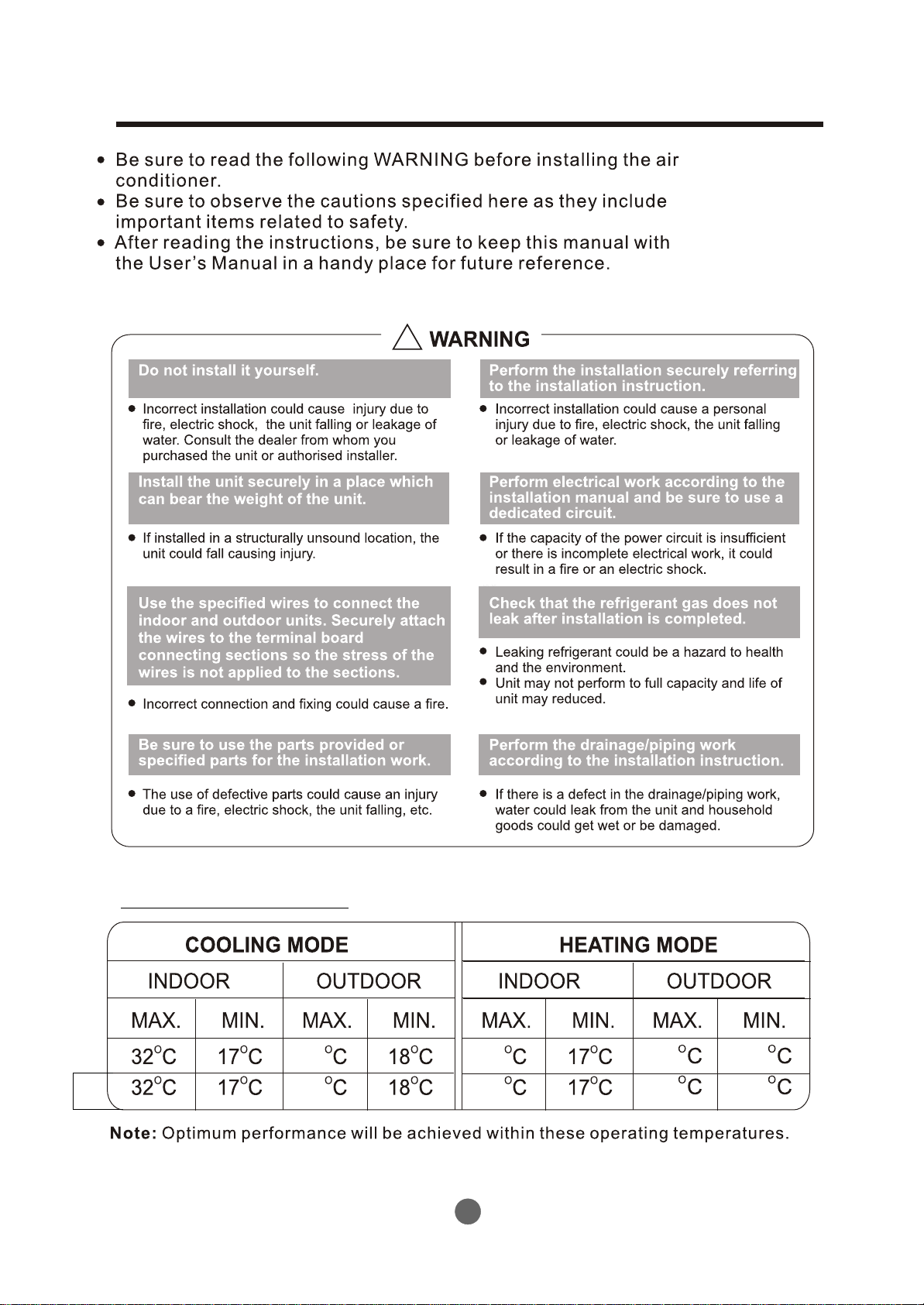
Warning .........................................................................................................................................
Operating temperature ..................................................................................................................
BEFORE INSTALLATION
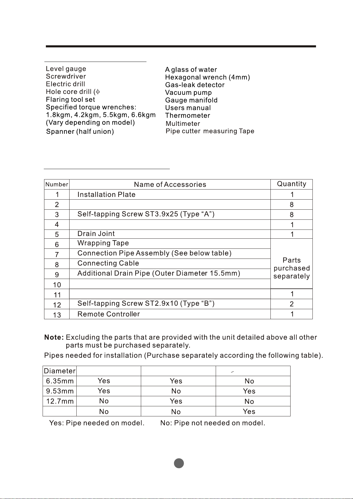
Tools needed for installation .......................................................................................................
Items required for installing the unit ..............................................................................................
Typical installation...........................................................................................................................
INSTALLATION
Installation .....................................................................................................................................
REFRIGERANT PIPE CONNECTION
Refrigerant pipe connection ........................................................................................................
ELECTRICAL WORK
Connecting the cable to the indoor unit ......................................................................................
Connecting the cable to the outdoor unit ....................................................................................
CHECKING THE DRAINAGE AND FORMING THE PIPING
Checking the drainage ................................................................................................................
Forming the piping ......................................................................................................................
2
2
3
3
4
5
10
17
18
19
19
AIR PURGING
Air purging ...................................................................................................................................
Safety and leakage check ...........................................................................................................
TEST RUNNING
Test running ...............................................................................................................................
Read This Manual
Inside you will find many helpful hints on how to install and test the air conditioner properly.
CAUTION
!
Contact an authorised service technician for repair or maintenance of this unit.
Contact an authorised installer for installation of this unit.
The air conditioner is not intended for use by young children or infirmed persons without supervision.
Young children should be supervised to ensure that they do not play with the air conditioner.
If the power cord is to be replaced, replacement work shall be performed by authorised personnel only.
Installation work must be performed in accordance with the national wiring Standards by authorised
personnel only.
Take care not to catch fingers on the fan when adjusting vertical louvres.
may use R22, R407C or
This air conditioner R410A refrigerant (Confirmed before installation)
IMPORTANNT NOTES
20
22
22
1
Page 3
SAFETY PRECAUTIONS
!
OPERATING TEMPERATURE
T3
43
54
2
30
30
24
24
-5
-7
Page 4
BEFORE INSTALLATION
Tools needed for installation
65mm or 95mm)
Items required for installing the unit
Clip Anchor
Seal (See page 10 for details)
(See page 10 for details)
Insulation materials
Cable Tie (5~10)
7,000 &9,000Btu/h model
12,000 &18,000Btu/h model
>21,000Btu/h model
16.0mm
3
Page 5
BEFORE INSTALLATION
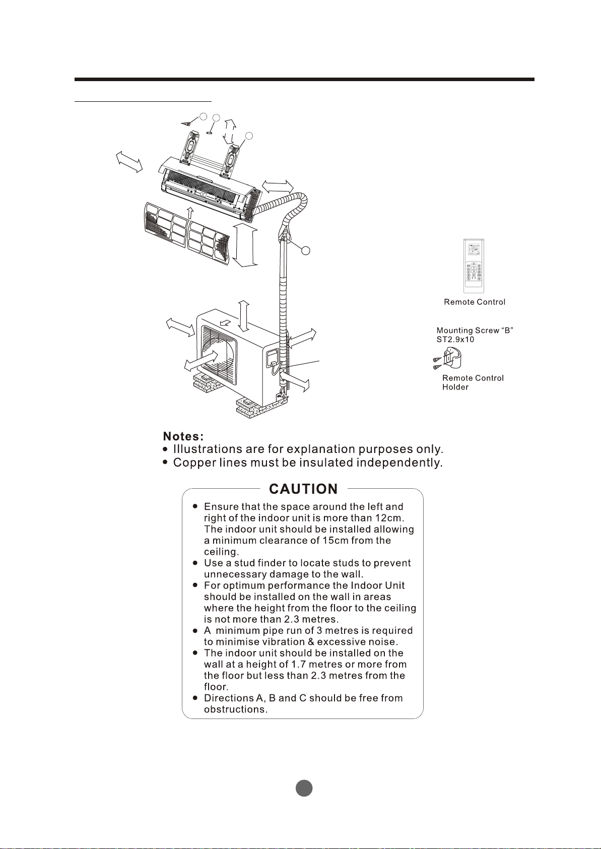
Typical installation
Self-tapping Screw A
12cm
abo
ve
A
10cm abov
B
e
100cm above
3
Air Filter
2
Air Outlet
Clip Anchor
15cm above
Installation Plate
1
12cm above
m
7
.
.3m
1
2
n
an
ha
h
t
t
ess
L
Mole
ve
bo
a
0cm
6
Connecting
6
pipe Assembly
e
abov
20cm
Loop the
connective
60cm
cable.
above
C
(If applicable)
4
Page 6
INSTALLATION
Installation
Read completely then follow step by step.
Indoor unit
Fig.1
Outdoor unit
Rooftop installatiom
2
2
Fig.2
5
Page 7
INSTALLATION
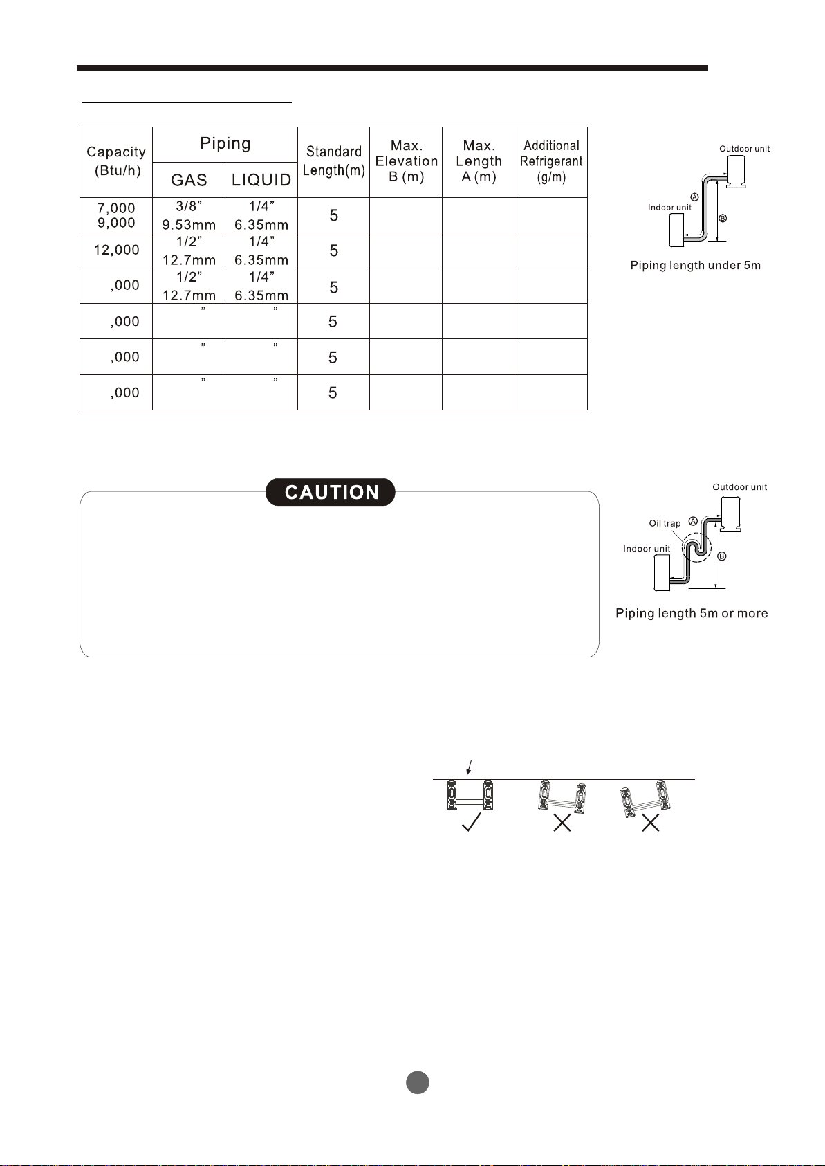
Piping length elevation
8
8
18
21 40
24
30 40
5/8
16.0mm
5/8
16.0mm
5/8
16.0mm
3/8
9.53mm
3/8
9.53mm
3/8
9.53mm
8
10 25
10
10
20
20
20
25
25
15
15
15
40
Capacity is based on standard length and maximum allowance
length is on the basis of reliability.
Oil trap should be installed every 5~7 metres.
When the connecting pipe is longer than 5 metres, additional
refrigerant should be added into the unit according to the
above table through the service port on the “LO” valve on
outdoor unit.
Fig.3
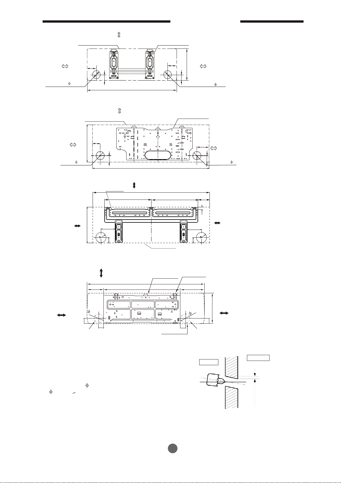
Indoor unit installation
1. Fit the Installation Plate
1). Fit the installation plate horizontally
on structural parts of the wall with
spaces around the installation plate.
2). If the wall is made of brick, concrete or
the like, drill eight (8) 5mm diameter holes
in the wall. Insert Clip anchor for appropriate
mounting screws.
3). Fit the installation plate on the wall with eight
(8) type “A” screws.
Note:
Fit the Installation Plate and drill holes in the wall according to the wall structure and corresponding
mounting points on the installation plate.
(Dimensions are in “mm” unless otherwise stated)
Correct orientation
of Installation Plate
Fig.4
6
Page 8
INSTALLATION
120mm or more
to wall
Left rear side
refrigerant
pipe hole 65
120mm or more
to wall
Left rear side
refrigerant
pipe hole 65
150mm or more to ceiling
Indoor unit outline
45
40
A
Indoor size:A*B=710*250 or 790*265
150mm or more to ceiling
Indoor unit outline
45
B
45
A
Indoor size:A*B=850*305
Hooked Part
150mm or more from the ceiling
A
380
Installation plate
90
40
Installation plate
380
B
Right rear side
refrigerant
pipe hole 65
120mm or more
to wall
120mm or more
to wall
90
Right rear side
refrigerant
45
pipe hole 65
67
Fig’s 5
120mm or more
from the wall
B
130
65
0
5
Indoor Unit Outline
Indoor size:A*B=998*322
Above 150 from
the ceiling
Hooked Part
A
178
815
Above 120 from
the wall
95
55
Pipe hole
58
Indo
Indoor size:A*B=1250*325
2. Drill a hole in the wall
1. Determine hole positions according to
the diagram detailed in Fig.5. Drill
one (1) hole ( 65mm <998*322 or
95mm >1250*325) slanting slightly
to outdoor side.
2. Always use wall hole conduit when
drilling metal grid, metal plate or the like.
22
120mm or more
from the wall
130
65
0
5
Hooker Part
257
Above 120 from
B
55
ip
e ho
Indoor
the wall
le
Wall
Outdoor
5-7mm
95
55
or
u
ni
t o
utlin
P
e
Fig.6
7
Page 9

INSTALLATION
3. Connecting Pipe and Drainage Installation
1. Run the drain hose sloping downward. Do not install the drain hose as illustrated below.
Do not block water flow with a rise.
Do not put the end of the
drain hose into water.
Fig.7
2. When connecting an extension drain hose, insulate the connecting part of the extension
drain hose with a shield pipe, do not let the drain hose become slack.
Connecting pipe
1. For the left-hand and right-hand piping, remove the pipe cover from the side panel.
2. For the rear-right-hand and rear-left-hand piping, install the piping as shown. Bend the
connecting pipe to be laid at a height of 43mm or less from the wall.
3. Fix the end of the connecting pipe. (Refer to Tightening Connection in REFRIGERANT
PIPING CONNECTION)
Right-hand piping
Side Part cover
Left-hand piping
Rear-right piping
Rear-left piping
Indoor unit outline
.
.
.
.
.
.
.
.
.
.
.
.
.
.
.
.
.
.
.
.
.
.
.
.
.
.
.
.
.
.
.
.
.
.
.
.
.
.
.
.
.
.
.
.
.
.
.
.
.
.
.
.
.
.
.
.
.
.
.
.
.
.
.
.
.
.
.
.
.
.
.
.
.
.
.
.
.
.
.
.
.
.
.
.
.
.
.
.
.
.
.
.
Fig.9
.
.
.
.
.
.
.
.
.
.
.
.
.
.
.
.
.
.
.
.
.
.
.
Connecting pipe
.
.
.
.
.
.
.
.
.
.
.
.
.
.
.
.
.
.
.
.
.
.
.
.
.
.
Fig.8
43
.
.
.
.
.
.
.
.
.
.
.
.
.
.
.
4. Indoor unit installation
1. Pass the piping through the hole in the wall.
2. Put the upper claw at the back of the indoor unit on
the upper hook of the installation plate, move the
indoor unit from side to side to see that it is securely
hooked.
3. Piping can easily be made by lifting the indoor unit
with a cushioning material between the indoor unit
and the wall. Remove cushioning material after finish
piping.
4. Push the lower part of the indoor unit up on the wall,
Then move the indoor unit from side to side, up and
down to check if it is hooked securely.
8
Upper Hook
Lower Hook
Cushioning
material
Fig.10
Page 10

INSTALLATION
5. Piping and wrapping
Bundle the tubing, connecting cable, and
drain hose with tape securely and
evenly as shown in Fig.11.
Because the condensed water from rear
Indoor unit
Connecting
cable
of the indoor unit is gathered in ponding
box and is piped out of room. Do not put
anything else in this box.
Drain hose
Fig.11
CAUTION
Connect the indoor unit first, then the outdoor unit.
Do not allow the piping to be exposed out from the back of the indoor unit.
Be careful not to let the drain hose become slack.
Heat insulate the connecting piping.
Be sure that the drain hose is located at the lowest side of the bundle. Locating
at the upper side can cause drain pan to overflow inside the unit.
Never cross connect or inter wind the power wire with any other wiring.
Run the drain hose sloped downward to drain out the condensed water smoothly.
Outdoor unit installation
Ponding box
Pipe room
Connecting
pipe
Wrapping belt
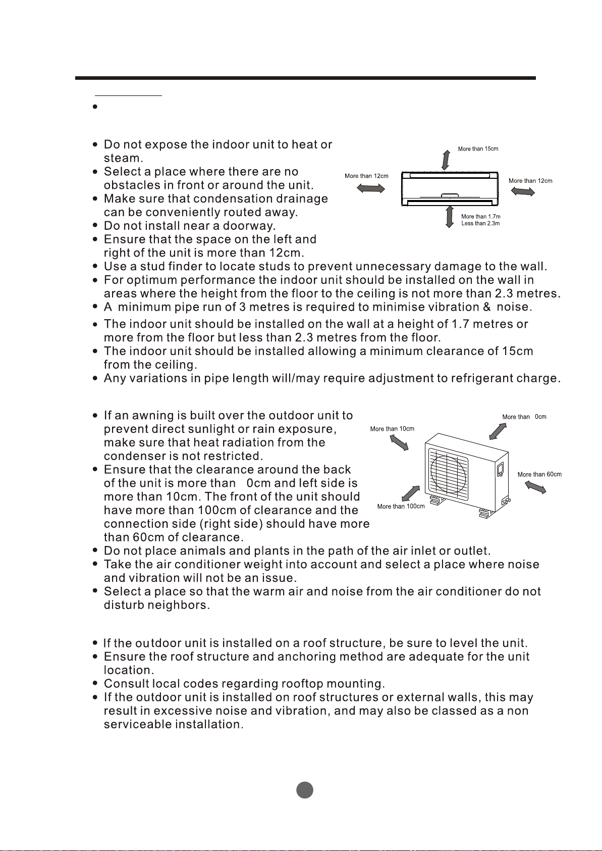
Outdoor unit installation precautions
Install the outdoor unit on a rigid base to prevent noise and vibration.
Select the air outlet direction so that discharged air is not blocked.
In the case where the installation location is exposed to strong winds,
make sure the fan operates properly by putting the unit lengthwise along the wall
or by using a shield to minimise wind exposure.
Especially in windy areas, install the unit to minimise exposure to wind.
For suspended installations, the installation bracket should follow with technique
requirement in the installation bracket diagram. The installation wall should be solid
brick, concrete or of same construction,
or reinforced to minimise movement or vibration.
The connection between the wall bracket and the
air conditioner should be firm, stable and reliable.
Ensure there lare no obstacles which block
Strong
wind
flow air.
Fig.12
9
Page 11

REFRIGERANT PIPE CONNECTION
Securing of outdoor unit
Anchor the outdoor unit with
a bolt and nut 10 or 8 tightly
and horizontally on a concrete
or rigid mount.
Outdoor unit dimension
Mounting dimensions
Air inlet
A
Air inlet
mm(WxHxD)
700x535x235
685x430x260
780x540x250
760x590x285
845x695x335
895x860x330
A(mm) B(mm)
458 250
460 276
549 276
530 290
560 335
590 333
Drain joint installation
If a drain elbow is used, the unit should be placed
on a stand which is taller than 3cm.
If the unit is used in an area where temperature
falls below 0 C for 2 or 3 days in succession, it
O
is recommended not to use a drain elbow, as the
drain water may freeze and the fan will not rotate.
Fit the seal into the drain elbow, then insert
the drain joint into the base pan hole of the
outdoor unit, rotate 90 to secure. Connect
the drain joint with an extension drain hose
(Locally purchased), in instances where you
need to drain condensed water away from the unit.
B
Air outlet
Fig.13
Seal
Drain joint
Base pan hole of
outdoor unit
Seal
Drain pipe
Fig.14
Refrigerant pipe connection
1. Flaring work
Main cause for refrigerant leakage
is due to defects in the flaring work.
Carry out correct flaring work
using the following procedure:
A: Cut the pipes and the cable.
1. Use the piping kit accessory (if applicable) or pipes
purchased locally.
2. Measure the distance between the indoor and the outdoor unit.
3. Cut the pipes a little longer than the measured distance.
4. Cut the cable 1.5m longer than the pipe length.
B: Burr removal
1. Completely remove all burrs from the cut
cross section of pipe/tube.
2. Face the end of the copper pipe/tube in a
downward direction as you remove burrs in
order to avoid burrs dropping into the tubing.
90 C
Face down
Oblique
Roughness
Fig.15
Pipe
Fig.16
Burr
Reamer
10
Page 12

REFRIGERANT PIPE CONNECTION
C: Putting flare nut on
Remove flare nuts attached to indoor and
outdoor unit, then put them on pipe/tube
having completed burr removal (Note: It is not
possible to put them on after flaring work).
D: Flaring work
Carry out flaring work using flaring tool as
shown below.
Firmly hold copper pipe in a die according
to the dimension shown in the table below.
Outer diam.
(mm)
6.35 (1/4”) 1.3
9.53 (3/8”)
12.7 (1/2”)
16.0 (5/8”)
A(mm)
Max.
Min.
0.7
1.6 1.0
1.8
1.8
2.4
1.0
1.0
2.2
Tightening Connection
Copper tube
Bar
"A"
Copper pipe
Clamp handle
Flare nut
Fig.17
Handle
Bar
Yoke
Cone
Red arrow mark
Fig.18
Align the center of the pipes.
Sufficiently tighten the flare
nut with fingers, and then tighten
it with a spanner and torque wrench
as shown.
Caution
Excessive torque can break nut
depending on installation conditions.
Indoor unit tubing Flare nut Pipings
Fig.19
Outer
diam.
6.35 (1/4”)
9.53 (3/8”)
12.7 (1/2”)
16.0 (5/8”)
Tightening
torque (kg.m)
1.6
3.0
5.0
7.5
Additional tightening
torque (kg.m)
2.0
3.5
5.5
8.0
11
Page 13

REFRIGERANT PIPE CONNECTION
E:
Check
Smooth all round
Even length
all round
Connetion of pipes - Indoor
Improper flaring
Tubing retainer
For Rear Right Piping
:
:
12
Rear right
Connecting cable
Front
Rear left
Drain hose
Piping
Page 14

REFRIGERANT PIPE CONNECTION
:
Insert the piping, drain hose and the
:
connecting cable into the piping hole.
:
:
Tubing retainer
Connecting
cable
:
13
Page 15

REFRIGERANT PIPE CONNECTION
:
For Rear Left Piping
:
:
:
Tubing retainer
14
Page 16

REFRIGERANT PIPE CONNECTION
:
:
:
:
15
Page 17

REFRIGERANT PIPE CONNECTION
:
:
:
.
Tubing retainer
Connecting
cable
Connection of pipes - outdoor
:
:
7.5
8
16
Page 18

ELECTRICAL WORK
Connect the cable to the indoor unit
Terminal block of indoor unit
1 2(N) S
To outdoor unit
7000Btu/h model
9000Btu/h model
12000Btu/h model
18000Btu/h model
24000Btu/h model
1
0
m
m
all models according to diagram
L N S
Cord clamp
To outdoor unit
30000Btu/h model
Front Panel
The supply voltage must be consistent with
the rate voltage of the air conditioner.
Connect the cable to the indoor unit
Electrical box
cover
NOTE: Before performing any electrical work, turn off the main power to the system.
7,000Btu/h
9,000Btu/h
12,000Btu/h
18,000Btu/h
21,000Btu/h
24,000Btu/h
30,000Btu/h
6
10A
16A
16A
16A
20A
1.0
1.5
1.5
1.5
2.5
Code wire
40m
m
17
Page 19

ELECTRICAL WORK
Connect the cable to the outdoor unit
:
:
:
:
7
Wire connector of outdoor unit
N
S
L
40m
1
0
m
m
m
Wire -holding board
18
Page 20

CHECKING THE DRAINAGE AND FORMING THE PIPING
Checking the drainage
:
.
:
:
Forming the piping
:
:
B
Water
leakage
Do not
raise
Water
leakage
Accumulated
drain water
Air
Water
leakage
Tip of drain hose
dipped in water
Ditch
Downward
slope
Less than
50mm gap
19
Page 21

AIR PURGING
:
C
Air purging
Air and moisture in the refrigerant system have undesirable effects as indicated below:
Pressure in the system rises.
Operating current rises.
Cooling or heating efficiency drops.
Moisture in the refrigerant circuit may freeze and block capillary tubing.
Water may lead to corrosion of parts in the refrigeration system.
Therefore, the indoor unit and tubing between the indoor and outdoor unit must be
leak tested and evacuated to remove any noncondensables and moisture from the
system.
Air purging with vacuum pump
Preparation
Check that each tube (both liquid and gas side tubes) between the indoor and
outdoor units have been properly connected and all wiring for the test run has
been completed. Remove the service valve caps from both the gas and the liquid
side on the outdoor unit. Note that both the liquid and the gas side service valves
on the outdoor unit are kept closed at this stage.
Pipe length and refrigerant amount:
Connecting
pipe length
Less than 5m
More than 5m
Air purging
method
Use vacuum
pump.
Use vacuum
pump.
Additional amount of refrigerant to be charged
6.35(Liquid side)
R22: (Pipe length-5) x 30g/m
R410A: (Pipe length-5) x 20g/m
9.52(Liquid side)
R22: (Pipe length-5) x 60g/m
R410A: (Pipe length-5) x 40g/m
20
Page 22

AIR PURGING
When relocate the unit to another place, perform evacuation using vacuum pump.
Make sure the refrigerant added into the air conditioner is in liquid form in any case.
(Not applicable to units that use freon R22 )
Caution in handling the packed valve
Open the valve stem until it hits against the stopper. Do not try to open it further.
Securely tighten the valve stem cap with a spanner or the like.
Valve stem cap tightening torque (See Tightening torque table on page 16 ).
Flare nut
Stopper
Cap
Valve stem
Fig.23
Outdoor
unit
Packed valve
A
B
Refrigerant
Gas side
Liquid side
Fig.22
Indoor
unit
C
D
Valve body
Half union
When Using the Vacuum Pump
(For method of using a manifold valve, refer to its operation manual.)
1. Completely tighten the flare nuts, A, B, C, D, connect the manifold valve charge
hose to a charge port of the low-pressure valve on the gas pipe side.
2. Connect the charge hose connection to the vacuum pump.
3. Fully open the handle Lo of the manifold valve.
4. Operate the vacuum pump to evacuate. After starting evacuation, slightly loose the
flare nut of the Lo valve on the gas pipe side and check that the air is entering
(Operation noise of the vacuum pump changes and a compound meter indicates
0 instead of minus)
5. After the evacuation is complete, fully close the
handle Lo of the manifold valve and stop the
operation of the vacuum pump.
Make evacuation for 15 minutes or more and
check that the compound meter indicates
-76cmHg (-1 x 10 Pa).
6. Turn the stem of the packed valve B about 45
5
o
Compound meter
-76cmHg
Handle Lo
Charge hose
Manifold valve
Pressure gauge
Handle Hi
Charge hose
Vacuum pump
counterclockwise for 6~7 seconds after the gas
coming out, then tighten the flare nut again. Make
sure the pressure display in the pressure indicator
is a little higher than the atmosphere pressure.
Low pressure valve
Fig.24
7. Remove the charge hose from the Low pressure charge hose.
8. Fully open the packed valve stems B and A.
9. Securely tighten the cap of the packed valve.
21
Page 23

TEST RUNNING
Safety and leakage check
Electrical safety check
Perform the electric safe check after completing installation:
1. Grounding work
After finishing grounding work, measure the grounding resistance by visual detection and
grounding resistance tester.
2. Electrical leakage check (performing during test running)
During test operation after finishing installation, the service person can use the electroprobe
and multimeter to perform the electrical leakage check. Turn off the unit immediately if
leakage happens. Check and find out the solution ways till the unit operate properly.
Gas leak check
1. Soap water method:
Apply a soap water or a liquid neutral detergent
on the indoor unit connection or outdoor unit
connections by a soft brush to check for leakage
of the connecting points of th piping. If bubbles
come out, the pipes have leakage.
Leak detector
2.
Use the leak detector to check for leakage.
CAUTION
Indoor unit
check point
Cover
Outdoor unit
check point
C
D
A
B
A: Lo packed valve B: Hi packed valve
C and D are ends of indoor unit connection.
Fig.25
Test running
Perform test operation after completing gas leak check at the flare nut connections and
electrical safety check.
Check that all tubing and wiring have been properly connected.
Check that the gas and liquid side service valves are fully open.
Connect the power, press the ON/OFF button on the remote controller to turn the unit on.
Use the MODE button to select COOL, HEAT, AUTO and FAN to check if all the functions
work well.
When the ambient temperature is too low (lower than 17 C), the unit cannot be controlled by
the remote controller to run at cooling mode, manual operation can be taken. Manual
operation is used only when the remote controller is disable or maintenance is necessary.
Hold the panel sides and lift the panel up to an angle until it remains fixed is a clicking
sound.
Press the Manual control button to select the AUTO or COOL, the unit will operate under
Forced AUTO or COOL mode (see User Manual for details).
The test operation should last about 30 minutes.
O
Manual control
button
AUTO/COOL
22
Page 24

TEST RUNNING
23
 Loading...