

Page 1
Website: www.mideaaircon.com
Service manual
CAUTION
- BEFORE SERVICING THE UNIT, READ THE SAFETY
- PRECAUTIONS IN THIS MANUAL.
- ONLY FOR AUTHORIZED SERVICE PERSONNEL.
MODELS:
EL-KF20GW/N2Y-A(B) EL-KFR20GW/N2Y-A(B) EL-KF26GW/N2Y-A(B) EL-KFR26GW/N2Y-A(B)
EL-KF36GW/N2Y-A(B) EL-KFR36GW/N2Y-A(B) EL-KF50GW/N2Y-A(B) EL-KFR50GW/N2Y-A(B)
EL-KF61GW/N2Y-A(B) EL-KFR61GW/N2Y-A(B) EL-KF70GW/N2Y-A(B) EL-KFR70GW/N2Y-A(B)
EL-KFR20GW/N1Y-A(B) EL-KFR26GW/N1Y-A(B) EL-KFR36GW/N1Y-A(B)
EL-KF20GW/Y-A(B) EL-KFR20GW/Y-A(B) EL-KF26GW/Y-A(B) EL-KFR26GW/Y-A(B)
EL-KF32GW/Y-A(B) EL-KFR32GW/Y-A(B) EL-KF36GW/Y-A(B) EL-KFR36GW/Y-A(B)
EL-KF50GW/Y-A(B) EL-KFR50GW/Y-A(B) EL-KF61GW/Y-A(B) EL-KFR61GW/Y-A(B)
EL-KF70GW/Y-A(B) EL-KFR70GW/Y-A(B) EL-KF90GW/Y-A(B) EL-KFR90GW/Y-A(B)
EL-KF90GW/SY-A(B) EL-KFR90GW/SY-A(B) AU-KF61GW/Y-A(B) AU-KFR61GW/Y-A(B)
AU-KF70GW/Y-A(B) AU-KFR70GW/Y-A(B) AU-KF85GW/Y-A(B) AU-KFR85GW/Y-A(B)
EL1-KF20GW/Y-A(B) EL1-KFR20GW/Y-A(B) EL1-KF26GW/Y-A(B) EL1-KFR26GW/Y-A(B)
EL1-KF32GW/Y-A(B) EL1-KFR32GW/Y-A(B) EL1-KF20GW/N2Y-A(B) EL1-KFR20GW/N2Y-A(B)
EL1-KF26GW/N2Y-A(B) EL1-KFR26GW/N2Y-A(B) EL1-KF35GW/N2Y-A(B) EL1-KFR35GW/N2Y-A(B)
EL-KT3F53GW/Y-T2 EL-KT3F53GW/Y-T1 EL-KT3FR53GW/Y-T1
EL-KT3F70GW/Y-T2 EL-KT3F70GW/Y-T1 EL-KT3FR70GW/Y-T1
SEL-KF20GW/Y-A(B) SEL-KFR20GW/Y-A(B) SEL-KF26GW/Y-A(B) SEL-KFR26GW/Y-A(B)
SEL-KF32GW/Y-A(B) SEL-KFR32GW/Y-A(B) SEL-KF53GW/Y-A(B) SEL-KFR53GW/Y-A(B)
SEL-KF61GW/Y-A(B) SEL-KFR61GW/Y-A(B) SEL-KF70GW/Y-A(B) SEL-KFR70GW/Y-A(B)
SEL1-KF26GW/Y-A(B) SEL1-KFR26GW/Y-A(B) SEL1-KF36GW/Y-A(B) SEL1-KFR36GW/Y-A(B)
0
Page 2

GD Midea Refrigerant Equipment Co. Ltd Service manual for Electrolux split Series
CONTENTS
1. PREFACE
1.1 SAFETY PRECAUTIONS........................................................................................................................1
1.2 INSULATION RESISTANCE TEST.........................................................................................................1
1.3 FEATURES...............................................................................................................................................2
1.4 CONTROL LOCATIONS.............................................................................................................................2
1.5 OUTSIDE DIMENSIONS............................................................................................................................3
2. INSTALLATION
2.1 TOOLS NEEDED FOR INSTALLATION....................................................................................................5
2.2 ITEMS REQUIRED FOR INSTALLING THE UNIT........................................ ............................................5
2.3 INSTALLATION OF INDOOR UNIT AND OUTDOOR UNIT ................................................................... ..6
2.4 FLARING WORK AND CONNECTION OF PIPING.................................................... ...............................8
2.5 CONNECTING THE CABLE BETWEEN INDOOR UNIT AND OUTDOOR UNIT……………..................12
2.6 CHECKING THE DRAINAGE AND FORMING THE PIPING ................................................ ....... ... ....... . .14
2.7 AIR PURGING.......................................... .................................................. ...............................................15
2.8 TEST RUNNING ............................................. ...................... ...................... ..............................................17
3. TROUBLE SHOOTING GUIDE
3.1 Refrigeration Cycle Diagram..................................... ................................................................................19
3.2 TROUBLE SHOOTING GUIDE..................................................................................................................20
4. WIRING DIAGRAM
4.1 Wiring diagram for indoor units……..........................................................................................................26
4.2 Wiring diagram for outdoor units...............................................................................................................32
5. EXPLODED VIEWS…………………………………………...........................................................................40
6 SPECIFICATIONS........................................................................................................................................40
7 SPARE PARTS LIST……………………………………………………..………….……………………………..40
8 MODEL CHECK LIST……………………………………………………………………………………………….40
1. PREFACE
This SERVICE MANUAL provides various servicing information, including the mechanical and electrical parts,
etc. This room air conditioner was manufactured and assembled under a strict quality control system.
The refrigerant is charged at the factory. Be sure to read the safety precautions prior to servicing the unit.
1.1 SAFETY PRECAUTIONS
1. When servicing the unit, set the POWER SWITCH to OFF and unplug the power cord.
2. Inspect the service cord for damage or wear.
If a short circuit is found, replace all parts which have been overheated or damaged by the short circuit.
3. After servicing the unit, make an insulation resistance test to protect the customer from being exposed to
shock hazards.
1.2 INSULATION RESISTANCE TEST
1. Unplug the power cord and connect a jumper lead between the two (2) live pins.
2. The grounding conductor (yellow/green) is to be open.
3. Measure the resistance value with an ohm meter between the jumped lead and each exposed metallic part
on the equipment at all the positions (except OFF) of the ROTARY SWITCH or POWER SWITCH.
4. The value should be over 1MΩ.
1
Page 3
1.3 FEATURES
Error self diagnosis function.
Anti-icing function at cooling mode.
Anti-cold air function at heating mode.
Auto-defrosting and heating recovering function
at heating mode.
Outdoor unit overload current protection.
Temperature protection of the outdoor
compressor top.
Restart protection for the compressor.
24 hours on/off mode time setting.
Protection against over-load or too-low current
input through alternating current.
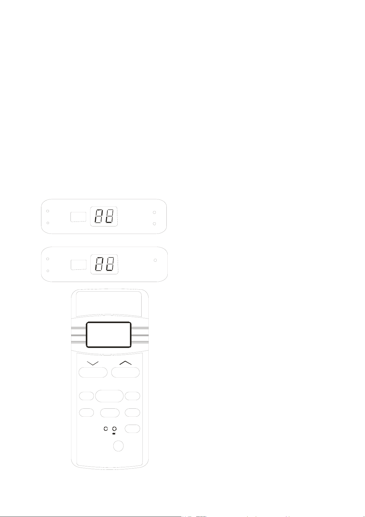
1.4 CONTROL LOCATIONS
For reverse cycle models:
R
M
E
I
T
℃
O
T
A
U
R
E
W
O
P
T
S
O
R
F
E
D
For cooling only models:
R
E
M
I
T
℃
O
T
A
U
AUTO
COOL
DRY
HEAT
TEMP
MODE ON/OFF
SWING ECONOM Y
RESET
R
DIGITAL DISPLAY
LOCK
TIME R
CANCEL
FAN
O
P
FAN
HIGH
MED
LOW
R
E
W
LED lamp:
POWER
AUTO
TIMER
DEFROST
Remote controller:
LCD display
Mode button: Select the operation mode, AUTO,
COOL, DRY, HEAT (Reverse cycle
models only) and F AN.
Fan speed button: Select the Fan speed, AUTO,
LOW, MED, HIGH.
ON/OFF button: Press this button to operation
the unit, again to stop.
Temperature setting up button: Press this
button to increase temperature
setting or adjust the TIMER in a
clockwise direction.
Temperature setting down button: Press this
button to decrease temperature
setting or adjust the TIMER in a
counter-clockwise direction.
Swing button: Press this button to activate the
auto swing, again to stop.
Economy button: Push this button to set the
economical operation mode.
Timer button: Press this button to set TIMER
ON and/or TIMER OFF.
Cancel button: Press this button to cancel
TIMER ON and TIMER OFF.
Lock button: Press this button to lock all button
except this button.
Reset button: Press this button to reset all
settings to original.
Digital display button: Press this button to
activate/eliminate the digital
temperature display on the indoor
unit.
2
Page 4
GD Midea Refrigerant Equipment Co. Ltd Service manual for Electrolux split Series
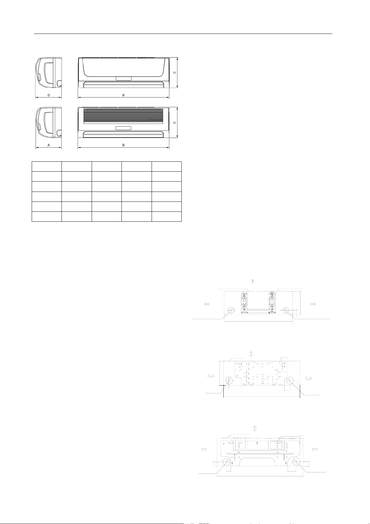
1.5 OUTSIDE DIMENSIONS
1.5.1 Indoor units:
A: width (mm) B: Depth (mm) C: Height (mm)
Unit A(mm) B(mm) C(mm) D(mm)
Size A 210 750 250 214
Size B 213 815 282 217
Size C 228 1000 298 232
Size D 240 1080 330 245
Size E 230 1250 325 230
Model list:
Size A indoor units:
EL-KF20GW/N2Y-A(B) EL-KFR20GW/N2Y-A(B)
EL-KF26GW/N2Y-A(B) EL-KFR26GW/N2Y-A(B)
EL-KFR20GW/N1Y-A(B) EL-KFR26GW/N1Y-A(B)
EL-KF20GW/Y-A(B) EL-KFR20GW/Y-A(B)
EL-KF26GW/Y-A(B) EL-KFR26GW/Y-A(B)
EL-KF32GW/Y-A(B) EL-KFR32GW/Y-A(B)
EL1-KF20GW/Y-A(B) EL1-KFR20GW/Y-A(B)
EL1-KF26GW/Y-A(B) EL1-KFR26GW/Y-A(B)
EL1-KF32GW/Y-A(B) EL1-KFR32GW/Y-A(B)
EL1-KF20GW/N2Y-A(B) EL1-KFR20GW/N2Y-A(B)
EL1-KF26GW/N2Y-A(B) EL1-KFR26GW/N2Y-A(B)
SEL-KF20GW/Y-A(B) SEL-KFR20GW/Y-A(B)
SEL-KF26GW/Y-A(B) SEL-KFR26GW/Y-A(B)
SEL-KF32GW/Y-A(B) SEL-KFR32GW/Y-A(B)
SEL1-KF26GW/Y-A(B) SEL1-KFR26GW/Y-A(B)
Size B indoor units:
EL-KF36GW/N2Y-A(B) EL-KFR36GW/N2Y-A(B)
EL-KFR36GW/N1Y-A(B)
EL-KF36GW/Y-A(B) EL-KFR36GW/Y-A(B)
EL1-KF35GW/N2Y-A(B) EL1-KFR35GW/N2Y-A(B)
SEL1-KF36GW/Y-A(B) SEL1-KFR36GW/Y-A(B)
Size C indoor units:
EL-KF50GW/N2Y-A(B) EL-KFR50GW/N2Y-A(B)
EL-KF50GW/Y-A(B) EL-KFR50GW/Y-A(B)
EL-KT3F53GW/Y-T2
EL-KT3F53GW/Y-T1 EL-KT3FR53GW/Y-T1
SEL-KF53GW/Y-A(B) SEL-KFR53GW/Y-A(B)
Size D indoor units:
EL-KF61GW/N2Y-A(B) EL-KFR61GW/N2Y-A(B)
EL-KF70GW/N2Y-A(B) EL-KFR70GW/N2Y-A(B)
EL-KF61GW/Y-A(B) EL-KFR61GW/Y-A(B)
EL-KF70GW/Y-A(B) EL-KFR70GW/Y-A(B)
AU-KF61GW/Y-A(B) AU-KFR61GW/Y-A(B)
AU-KF70GW/Y-A(B) AU-KFR70GW/Y-A(B)
EL-KT3F70GW/Y-T2
EL-KT3F70GW/Y-T1 EL-KT3FR70GW/Y-T1
SEL-KF61GW/Y-A(B) SEL-KFR61GW/Y-A(B)
SEL-KF70GW/Y-A(B) SEL-KFR70GW/Y-A(B)
Size E indoor units:
EL-KF90GW/Y-A(B) EL-KFR90GW/Y-A(B)
EL-KF90GW/SY-A(B) EL-KFR90GW/SY-A(B)
AU-KF85GW/Y-A(B) AU-KFR85GW/Y-A(B)
1.5.2 Installation plate
For Size A indoor unit:
120mm or m ore
to wal l
Left refrigerant
pipe ho le D65
Indoor unit outline
150mm or more to ceiling
750
Installation plate
45
250
Right refrigerant
pipe hole D65
For Size B indoor unit:
120mm or more
to wal l
Left refrigerant
pipe hole D65
Indoor unit outline
150mm or more to ceiling
280
815
Installation plate
50
50
Right refriger ant
pipe hole D 6 5
For Size C indoor unit:
150mm or more to the ceiling
Installation plate
1000
49
120mm or more
to the wal l
50
90
3
120mm or more
to the wa ll
Left pipe
hole D65
Indoor unit outl ine
50
55
120mm or more
to wall
120mm o r more
to wal l
Rig h t pi pe
hole D 65
Page 5
GD Midea Refrigerant Equipment Co. Ltd Service manual for Electrolux split Series
For Size D indoor unit:
Hooked Part
432
120mm o r more to
the wall
58
50
Left Pipe
hol e D95
115
465
For Size E indoor unit:
Ho oke d Par t
178
120mm or more
to the wall
55
Left pipe
hole D95
58
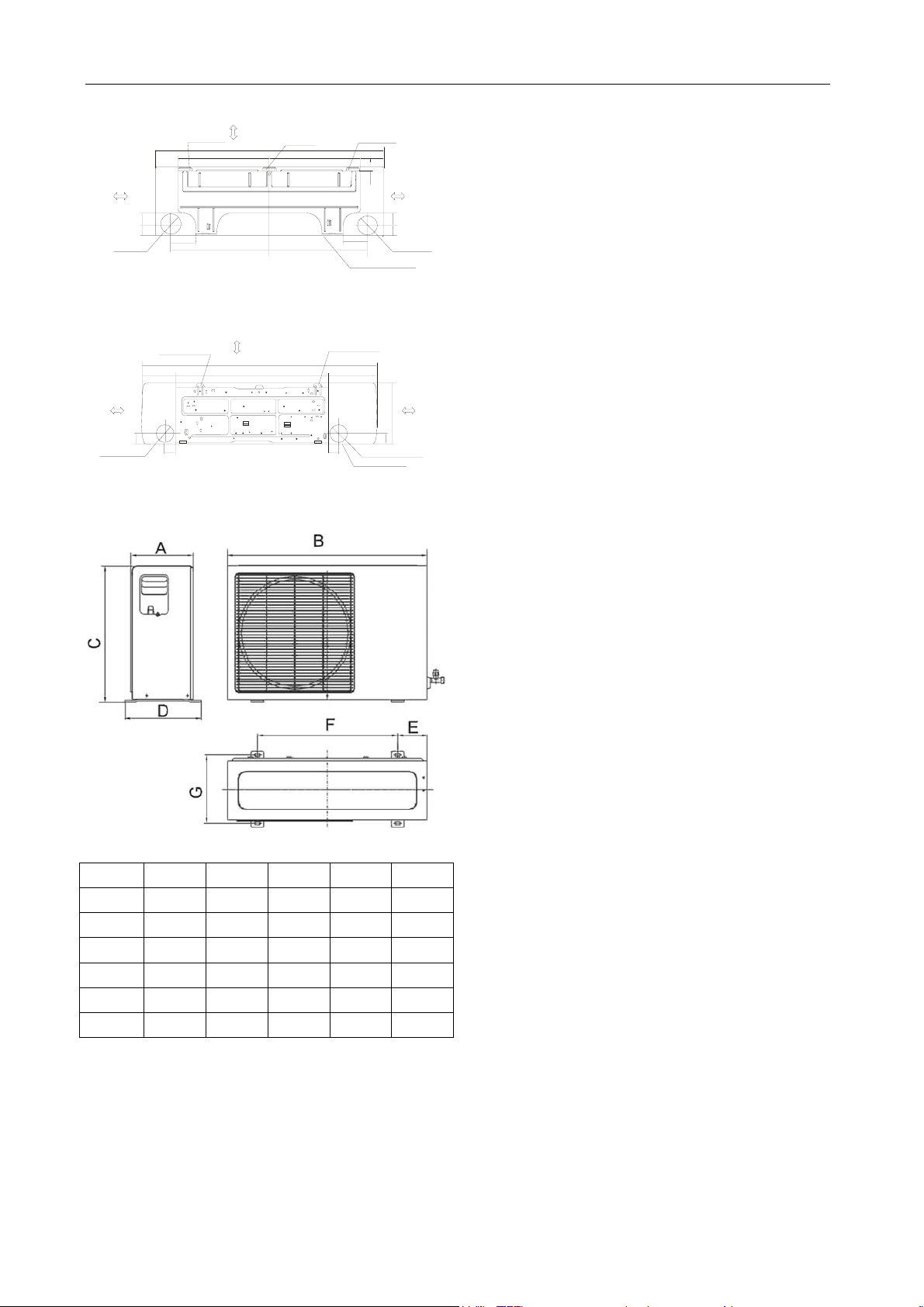
1.5.3 Outdoor units:
150 or more to the ceiling
Hooked Part
1080
150mm or mo re to the ceiling
1250
815
Hooked Part
432
465
Hooker Part
55
108
22
115
Indoor Unit Outline
257
R
g
i
h
t
I
n
d
o
o
r
u
n
120mm or more to
the wall
5850
Rig h t p ipe
hole D95
120mm or more
to the wa l l
325
55
p
i
p
e
h
o
e
D
9
l
5
t
o
e
u
l
t
n
i
i
EL1-KF20GW/Y-A(B) EL1-KFR20GW/Y-A(B)
EL1-KF26GW/Y-A(B) EL1-KFR26GW/Y-A(B)
EL1-KF20GW/N2Y-A(B) EL1-KFR20GW/N2Y-A(B)
EL1-KF26GW/N2Y-A(B) EL1-KFR26GW/N2Y-A(B)
SEL-KF20GW/Y-A(B) SEL-KFR20GW/Y-A(B)
SEL-KF26GW/Y-A(B) SEL-KFR26GW/Y-A(B)
Size G outdoor units:
EL-KFR26GW/N1Y-A(B) EL-KFR36GW/N1Y-A(B)
EL-KF32GW/Y-A(B) EL-KFR32GW/Y-A(B)
EL-KF36GW/Y-A(B) EL-KFR36GW/Y-A(B)
EL1-KF32GW/Y-A(B) EL1-KFR32GW/Y-A(B)
EL1-KF35GW/N2Y-A(B) EL1-KFR35GW/N2Y-A(B)
SEL-KF32GW/Y-A(B) SEL-KFR32GW/Y-A(B)
SEL1-KF26GW/Y-A(B) SEL1-KFR26GW/Y-A(B)
Size H outdoor units:
EL-KF36GW/N2Y-A(B) EL-KFR36GW/N2Y-A(B)
SEL1-KF36GW/Y-A(B) SEL1-KFR36GW/Y-A(B)
Size I outdoor units:
EL-KF50GW/N2Y-A(B) EL-KFR50GW/N2Y-A(B)
EL-KF61GW/N2Y-A(B) EL-KFR61GW/N2Y-A(B)
EL-KF70GW/N2Y-A(B) EL-KFR70GW/N2Y-A(B)
EL-KF50GW/Y-A(B) EL-KFR50GW/Y-A(B)
EL-KF61GW/Y-A(B) EL-KFR61GW/Y-A(B)
EL-KF70GW/Y-A(B) EL-KFR70GW/Y-A(B)
AU-KF61GW/Y-A(B) AU-KFR61GW/Y-A(B)
AU-KF70GW/Y-A(B) AU-KFR70GW/Y-A(B)
EL-KT3F53GW/Y-T2
EL-KT3F53GW/Y-T1 EL-KT3FR53GW/Y-T1
EL-KT3F70GW/Y-T1 EL-KT3FR70GW/Y-T1
SEL-KF53GW/Y-A(B) SEL-KFR53GW/Y-A(B)
SEL-KF61GW/Y-A(B) SEL-KFR61GW/Y-A(B)
A: Depth (mm) B: Width (mm) C: Height (mm)
Unit Size F Size G Size H Size I Size J
A(mm) 235 250 285 335 330
B(mm) 700 780 760 845 895
C(mm) 535 540 590 695 860
D(mm) 275 298 315 360 355
E(mm) 120 114.5 110 140 141.3
F(mm) 458 549 530 560 589.6
Size F outdoor units:
EL-KF20GW/N2Y-A(B) EL-KFR20GW/N2Y-A(B)
EL-KF26GW/N2Y-A(B) EL-KFR26GW/N2Y-A(B)
EL-KFR20GW/N1Y-A(B)
EL-KF20GW/Y-A(B) EL-KFR20GW/Y-A(B)
EL-KF26GW/Y-A(B) EL-KFR26GW/Y-A(B)
SEL-KF70GW/Y-A(B) SEL-KFR70GW/Y-A(B)
Size J outdoor units:
EL-KF90GW/Y-A(B) EL-KFR90GW/Y-A(B)
EL-KF90GW/SY-A(B) EL-KFR90GW/SY-A(B)
AU-KF85GW/Y-A(B) AU-KFR85GW/Y-A(B)
EL-KT3F70GW/Y-T2
4
Page 6
GD Midea Refrigerant Equipment Co. Ltd Service manual for Electrolux split Series
2 INSTALLATION
2.1 TOOLS NEEDED FOR INSTALLATION
Level gauge
Screwdriver
Electric drill
Hole core drill ( φ85mm or φ115mm depending
on Model)
Flaring tool set
Specified torque wrenches: 1.8kgm, 4.2kgm,
5.5kgm, 6.6kgm (Vary depending on model
No.)
Spanner (half union)
A glass of water
Hexagonal wrench (4mm)
Gas-leak detector
Vacuum pump
Gauge manifold
User’s manual
Thermometer
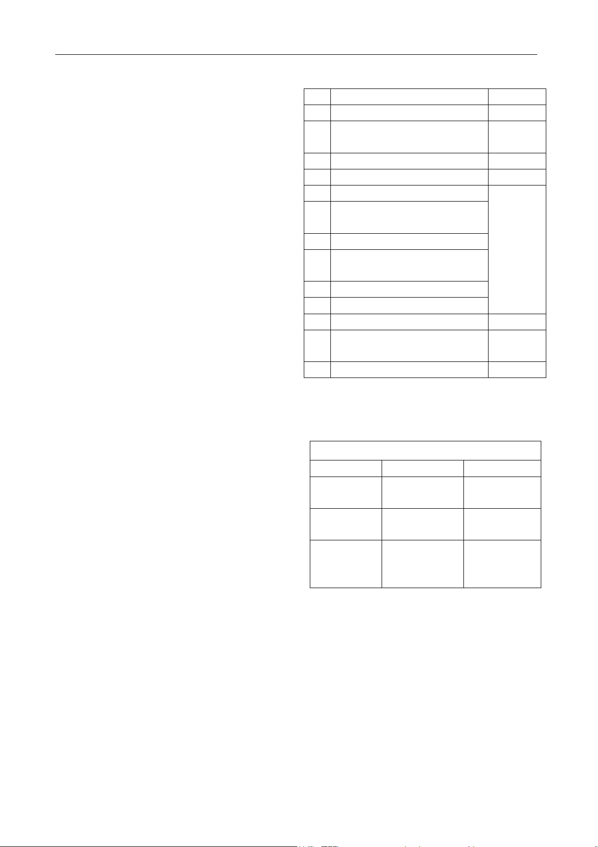
2.2 ITEMS REQUIRED FOR INSTALLING THE
UNIT
No. Name of Accessories Quantity
1 Installation Plate 1
2 Self-tapping Screw ST3.9x25
8
(Type “A”)
3 Plastic Expansion Sheath 8
4 Drain Joint 1
5 Wrapping Tape
6 Connection Pipe Assembly
(Detail in below table)
7 Connecting Cable
8 Additional Drain Pipe (Outer
Parts
purchased
separately
Diameter15.5mm)
9 Insulation Materials
10 Cable Tie (5~10)
11 Remote Control Holder 1
12 Self-tapping Screw ST2.9x10
2
(Type “B”)
13 Remote Control 1
Note: Excluding the parts that are provided with
the unit detailed above all other parts must be
purchased separately.
Connection Pipe Assembly
model Liquid side pipe Gas side pipe
7,000Btu/h
9,000Btu/h
12,000Btu/h
18,000Btu/h
21,000Btu/h
24,000Btu/h
6.35mm
1/4”
6.35mm
1/4”
9.53mm
3/8”
9.53mm
3/8”
12.7mm
1/2”
16mm
5/8”
30,000Btu/h
NOTE: For pipes used on R410A system, the
wall thickness of the pipes should be
no less than 0.7mm. Otherwise, the
pipes may be broken when using.
5
Page 7
GD Midea Refrigerant Equipment Co. Ltd Service manual for Electrolux split Series
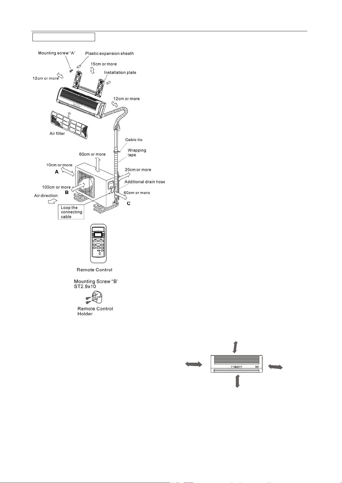
Typical installation
CAUTIONS:
1. Ensure that the space around the left and
right of the indoor unit is more than 12cm.
2. The indoor unit should be installed allowing a
minimum clearance of 15cm from the ceiling.
3. Use a stud finder to locate studs to prevent
unnecessary damage to the wall.
4. For optimum performance the Indoor Unit
should be installed on the wall in areas where
the height from the floor to the ceiling is not
more than 2.3 meters.
5. A minimum pipe run of 3 meters is required to
minimize vibration & excessive noise.
6. The indoor unit should be installed on the wall
at a height of 1.7 meters or more from the
floor but less than 2.3 meters from the floor.
7. Directions A, B and C should be free from
obstructions.
2.3 INSTALLATION OF INDOOR UNIT AND
OUTDOOR
2.3.1 Indoor unit
● Do not expose the indoor unit to heat or
steam.
● Select a place where there are no obstacles in
front or around the unit.
● Make sure that condensation drainage can be
conveniently routed away.
● Do not install near a doorway.
● Ensure that the space on the left and right of
the unit is more than 12cm.
● Use a stud finder to locate studs to prevent
unnecessary damage to the wall.
● For optimum performance the indoor unit
should be installed on the wall in areas where the
height from the floor to the ceiling is not more than
2.3 meters.
● A minimum pipe run of 3 meters is required to
minimize vibration & excessive noise.
● The indoor unit should be installed on the wall
at a height of 1.7 meters or more from the floor but
less than 2.3 meters from the floor.
● The indoor unit should be installed allowing a
minimum clearance of 15cm from the ceiling.
● Any variations in pipe length will/may require
adjustment to refrigerant charge (Refer to item
2.3.3).
m
c
5
1
n
a
h
t
r
e
Mo
More than 12cm
M
o
s
e
L
r
e
t
h
a
s
n
t
a
h
More than 12cm
n
.
1
m
7
.
2
m
3
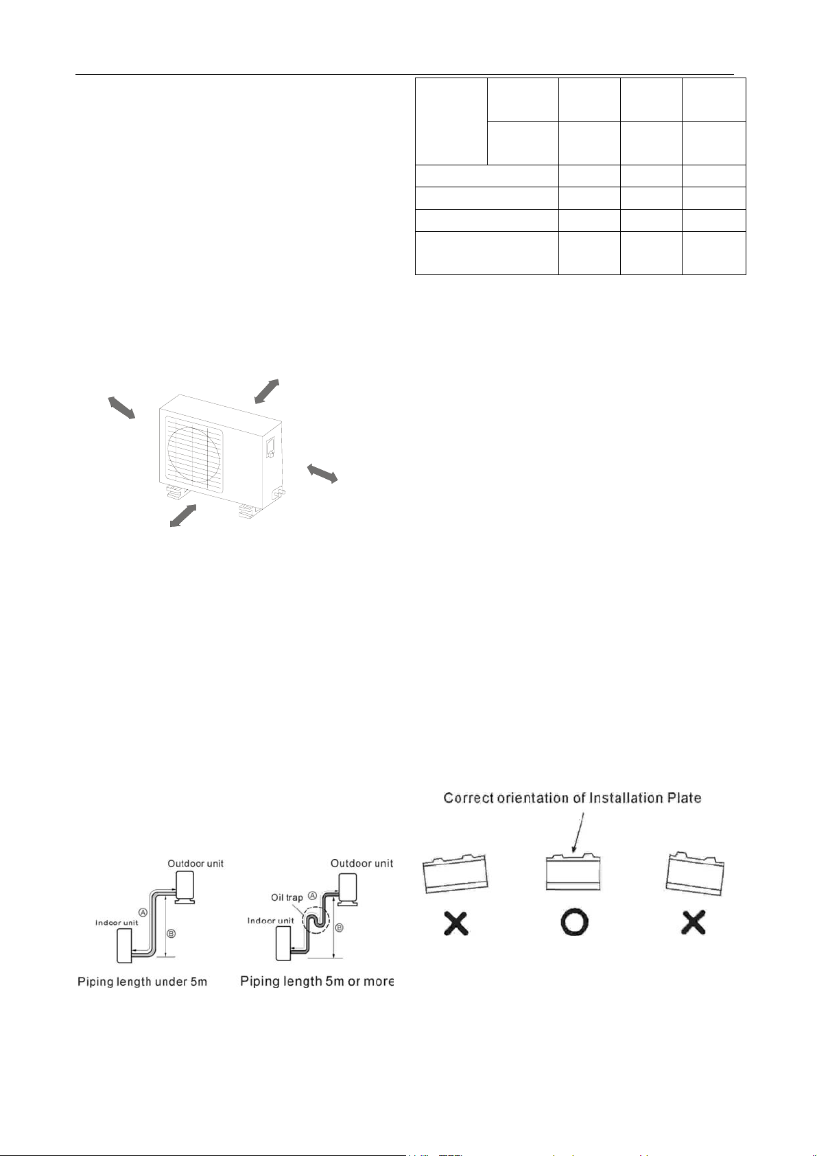
2.3.2 Outdoor unit
● If an awning is built over the outdoor unit to
prevent direct sunlight or rain exposure, make
sure that heat radiation from the condenser is not
restricted.
6
Page 8
GD Midea Refrigerant Equipment Co. Ltd Service manual for Electrolux split Series
2
0
● Ensure that the clearance around the back of
the unit is more than 20cm and left side is more
than 10cm.
● The front of the unit should have more than
100cm of clearance and the connection side (right
side) should have more than 60cm of clearance.
● Do not place animals and plants in the path of
the air inlet or outlet.
● Take the air conditioner weight into account
and select a place where noise and vibration will
not be an issue.
● Select a place so that the warm air and noise
from the air conditioner do not disturb neighbors.
m
c
n
h
a
t
e
r
Mo
m
0
c
1
n
h
a
t
e
r
Mo
GAS
Piping
LIQUID
3/8”
9.53mm
1/4”
6.35mm
Standard Length(m) 5 5 5
Max. Elevation B (m) 5 5 5
Max. Length A (m) 10 10 10
Additional
Refrigerant (g/m)
30 30 65
Cautions:
● Capacity is based on standard length and
maximum allowance length is on the basis of
reliability.
● Oil trap should be installed every 5~7 meters.
● When the connecting pipe is longer than 5
1/2”
12.7mm
1/4”
6.35mm
5/8”
16.0mm
3/8”
9.53mm
meters, Additional refrigerant should be added
into the unit according to the above table through
Mo
the service port on the “LO” valve on outdoor unit.
c
m
0
6
n
a
h
t
e
r
2.3.4 Fitting the installation plate
Fit the Installation Plate and drill holes in the wall
M
Rooftop installation:
● If the outdoor unit is installed on a roof
structure, be sure to level the unit.
● Ensure the roof structure and anchoring
method are adequate for the unit location.
● Consult local codes regarding to rooftop
mounting.
● If the outdoor unit is installed on roof
structures or external walls, this may result in
excessive noise and vibration, and may also be
according to the wall structure and corresponding
mounting points on the installation plate.
1. Fit the installation plate horizontally on
structural parts of the wall with spaces around the
installation plate (Detailed on page 3 as
applicable).
2. If the wall is made of brick, concrete or the like,
drill eight (8) 5mm diameter holes in the wall.
Insert Plastic Expansion Sheath for appropriate
mounting screws.
3. Fit the installation plate on the wall with eight (8)
type “A” screws.
m
0
c
0
1
t
h
an
e
r
o
classed as a non serviceable installation.
2.3.3 Piping length and elevation
2.3.5 Drill a hole in the wall
1. Determine hole positions according to the
diagram detailed on page 3 as applicable. Drill
one (1) hole (φ85mm for those models need
φ65mm pipe hole or φ115mm for models need
φ95mm pipe hole) slanting slightly to outdoor
7
Page 9
GD Midea Refrigerant Equipment Co. Ltd Service manual for Electrolux split Series
side.
2. Always use wall hole
conduit when drilling
metal grid, metal plate
or the like.
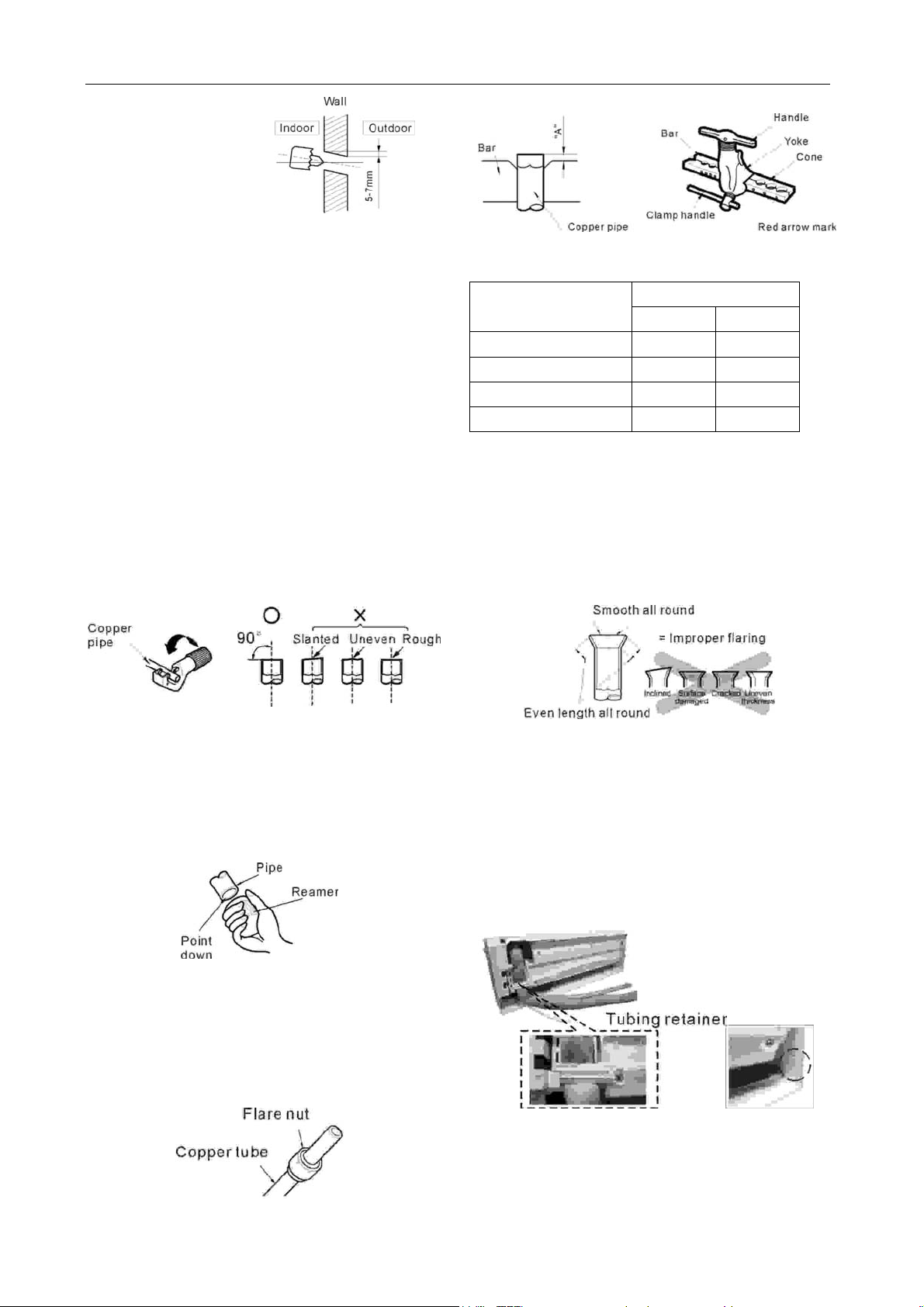
2.4 FLARING WORK AND CONNECTION OF
PIPING
The main cause for gas leakage is due to defects
in flaring work. Carry out correct flaring work using
the following procedure.
2.4.1 Flaring work
2.4.1.1 Cut the pipes and the cable.
● Use the piping kit accessory (if applicable) or
the pipes purchased locally.
● Measure the distance between the indoor and
the outdoor unit.
● Cut the pipes a little longer than measured
distance.
● Cut the cable 1.5m longer than the pipe
length.
2.4.1.4 Flaring work
● Carry out flaring work using flaring tool as
shown below.
Out diameter
“A” (mm)
Max. Min.
1/4” (6.35mm) 1.3 0.7
3/8” (9.53mm) 1.6 1.0
1/2” (12.7mm) 1.8 1.0
5/8” (16.0mm) 2.4 1.8
Hold copper pipe firmly in a die according to the
dimension shown in the table above.
2.4.1.5 Check
● Compare the flared work with the adjacent
diagram.
● If flare is found to be defective, cut off the
flared section and do flaring work again.
2.4.1.2 Burrs removal
● Completely remove all burrs from the cut cross
section of pipe/tube.
● Place the end of the copper tube/pipe in a
downward direction as you remove burrs in order
to avoid dropping burrs into the tubing.
2.4.1.3 Putting flare nut on
● Remove flare nuts attached to indoor and
outdoor unit, then put them on pipe/tube having
completed burr removal.
(Note: It is not possible to put them on after flaring
work.)
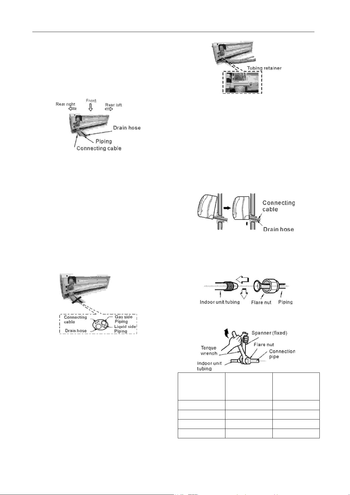
2.4.2 Connection of pipes - Indoor
● Prepare the indoor unit’s pipi ng and drain ho se
for installation through the wall.
● Remove the tubing retainer (see illustration
right) and pull the tubing and drain hose away
from chassis (If required). For some models thi s is
not needed.
Replace the tubing retainer in its original position.
CAUTION
When installing the indoor unit, be sure to remove
the relevant sections where required (see
8
Page 10
GD Midea Refrigerant Equipment Co. Ltd Service manual for Electrolux split Series
adjacent diagram for example). This will allow
piping and cable routing to be completed without
damaging the unit.
2.4.2.1 For rear right piping
Note: When viewed from the front of the indoor
unit.
2.4.2.1.1 Route the indoor tubing and the drain
hose in the direction of rear right.
2.4.2.1.2 Insert the connecting cable into the
indoor unit from the outdoor unit through the
piping hole.
● Do not connect the cable to the indoor unit.
● Make a small loop with the cable for easy
connection later.
2.4.2.1.3 Tape the tubing, drain hose and the
connecting cable. Be sure that the drain hose is
located at the lowest side of the bundle. Locating
at the upper side can cause drain pan to overflow
inside the unit.
2.4.2.1.6 Locating the indoor unit
● Hook the indoor unit onto the upper portion of
the installation plate (Engage the hooks of the
installation plate into the openings at the rear
top of the indoor unit). Ensure that the hooks are
properly seated on the installation plate by moving
the indoor unit left and right.
● Press the lower left and right sides of the unit
against the installation plate until the hooks
engage into their slots (clicking sound).
2.4.2.1.7 Connecting the piping to the indoor unit
and the drain hose to drain pipe.
● Align the centre of the piping and sufficiently
tighten the flare nut by hand.
Note: If the drain hose is routed inside the room,
insulate the hose with an insulation material so
that dripping from "sweating" (condensation) will
not damage furniture or floors.
*Foamed polyethylene or equivalent is
recommended.
2.4.2.1.4 Insert the piping, drain hose and the
connecting cable into the piping hole.
2.4.2.1.5 Set the piping and the drain hose to the
back of the chassis with the tubing holder.
● Set the tubing retainer into position and tighten
screw.
● Tighten the flare nut with a wrench, in
accordance with the following table.
Outside
Diameter
1/4” (6.35mm) 1.6 2.0
3/8” (9.53mm) 3.0 3.5
1/2” (12.7mm) 5.0 5.5
5/8” (16.0mm) 7.5 8.5
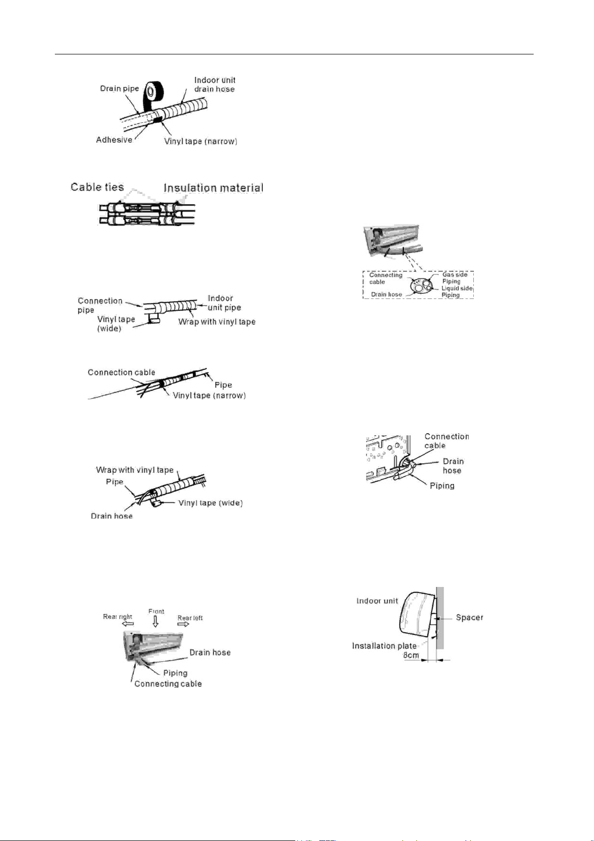
● When extending the drain hose of the indoor
unit, install the drain pipe extension as shown in
9
Tightening
Torque
(Kg.m)
Additional
Tightening
Torque (Kg.m)
Page 11
GD Midea Refrigerant Equipment Co. Ltd Service manual for Electrolux split Series
adjacent diagram.
2.4.2.1.8 Wrap the insulation material around the
connecting portion.
● Overlap the connection pipe heat insulation
and the indoor unit pipe heat insulation material.
Bind them together with vinyl tape so that there is
no gap.
● Wrap the area which accommodates the rear
piping housing section with vinyl tape.
● Bundle the piping and drain hose together by
wrapping them with vinyl tape over the range
within which they fit into the rear piping housing
section.
indoor unit from the outdoor unit through the
piping hole.
● Do not connect the cable to the indoor unit.
● Make a small loop with the cable for easy
connection later.
2.4.2.2.3 Tape the drain hose and the connecting
cable. Be sure that the drain hose is located at the
lowest side of the bundle. Locating at the upper
side can cause drain pan to overflow inside the
unit.
Note: If the drain hose is routed inside the room,
insulate the hose with an insulation material so
that dripping from "sweating" (condensation) will
not damage furniture or floors.
*Foamed polyethylene or equivalent is
recommended.
2.4.2.2.4 Insert the piping, drain hose and the
connecting cable into the piping hole.
2.4.2.2 For rear left piping
Note: When viewed from the front of the indoor
unit.
2.4.2.2.1 Route the indoor tubing and the drain
hose to the required piping hole position in the
direction of left.
2.4.2.2.2 Insert the connecting cable into the
2.4.2.2.5 Indoor unit installation
● Hang the indoor unit from the hooks at the top
of the installation plate.
● Insert a spacer between the indoor unit and
the installation plate to separate the bottom of the
indoor unit from the wall.
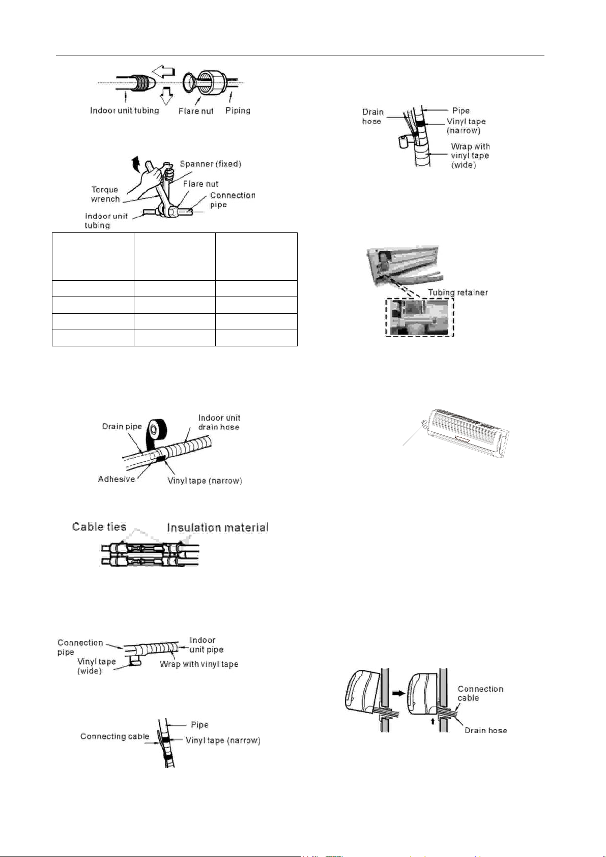
2.4.2.2.6 Connecting the piping to the indoor unit
and the drain hose to drain pipe.
● Align the centre of the piping and sufficiently
tighten the flare nut by hand.
10
Page 12
GD Midea Refrigerant Equipment Co. Ltd Service manual for Electrolux split Series
wrapping them with vinyl tape over the range
within which they fit into the rear piping
housing section.
● Tighten the flare nut with a wrench, in
accordance with the following table.
2.4.2.2.8 Set the piping and the drain hose to the
back of the chassis with the tubing holder.
● Set the tubing retainer into position and
Outside
Diameter
1/4” (6.35mm) 1.6 2.0
3/8” (9.53mm) 3.0 3.5
1/2” (12.7mm) 5.0 5.5
5/8” (16.0mm) 7.5 8.5
Tightening
Torque
(Kg.m)
Additional
Tightening
Torque (Kg.m)
● When extending the drain hose of the indoor
unit, install the drain pipe extension as shown in
adjacent diagram.
tighten screw.
2.4.2.2.9 Reroute the piping and the drain hose
across the back of the chassis, for rear left side
external passage.
2.4.2.2.7 Wrap the insulation material around the
piping connections.
● Overlap the connection pipe heat insulation
and the indoor unit pipe heat insulation
material. Bind them together with vinyl tape
so that there is no gap.
● Wrap the area which accommodates the rear
piping housing section with vinyl tape.
Piping for passage
th r ough piping hole
2.4.2.2.10 Locating the indoor unit
● Remove the spacer.
● Hook the indoor unit onto the upper portion of
the installation plate.
(Engage the two hooks of the installation plate
into the openings at the rear top of the indoor unit.)
● Ensure that the hooks are properly seated on
the installation plate by moving the indoor unit left
and right.
● Press the lower left and right sides of the unit
against the installation plate until the hooks
engage into their slots (clicking sound).
● Bundle the piping and drain hose together by
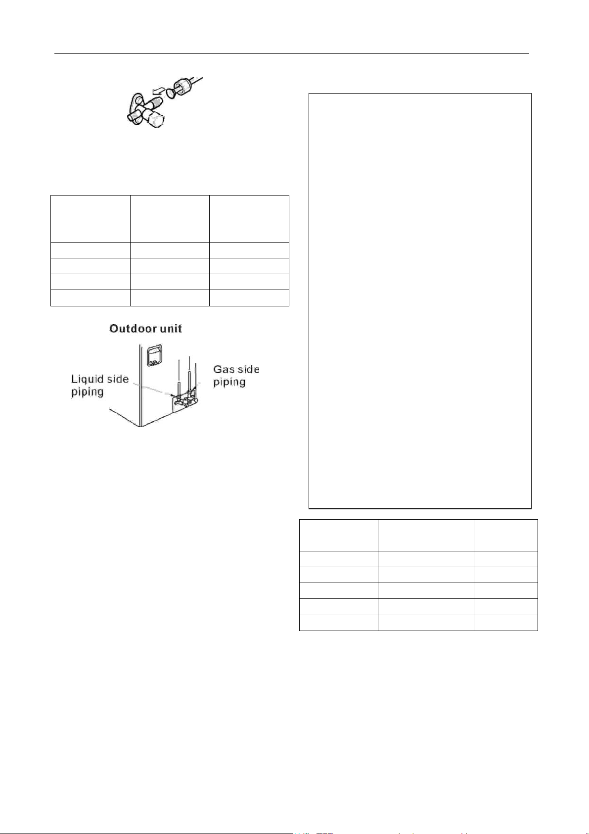
2.4.3 Connection of pipes - outdoor
2.4.3.1 Align the centre of the piping and
11
Page 13
GD Midea Refrigerant Equipment Co. Ltd Service manual for Electrolux split Series
sufficiently tighten the flare nut by hand.
2.4.3.2 Finally, tighten the flare nut with torque
wrench until the wrench clicks.
● Tighten the flare nut with a wrench, in
accordance with the following table.
Outside
Diameter
1/4” (6.35mm) 1.6 2.0
3/8” (9.53mm) 3.0 3.5
1/2” (12.7mm) 5.0 5.5
5/8” (16.0mm) 7.5 8.5
Tightening
Torque
(Kg.m)
Additional
Tightening
Torque (Kg.m)
2.5 CONNECTING THE CABLE BETWEEN
INDOOR UNIT AND OUTDOOR UNIT
CAUTION
Ensure that all electrical work complies with
relevant Stan dards and Supply Authority
Service Rules.
An individual branch Circuit Breaker/Fuse must
be used with this Air Conditioner. See the
table following for electrical requirements.
Notes:
● Power Source and Power Cord
specifications must comply with requirements
following.
● Circuit Breaker or Fuse specified in this
manual must be installed in the power supply
circuit.
● For your safety and protection, this unit is
earthed through the power cord plug when
plugged into a matching wall receptacle.
● Do not connect two power cords together to
supply power to the air conditioner.
● Do not extend the power cable conductors
by cutting.
● Power supply should be in the range of
90%~110% of rated voltage.
● Refer to the attached Electrical Connection
Diagram located on the panel of the outdoor
unit to connect the wire.
Max. current
(A)
<=8 10 >=1.0
>8 & <=12.5 16 >=1.5
>12.5 & <=16 20 >=2.5
>16 & <=25 32 >=4.0
>25 & <=32 40 >=6.0
Max. current (A): Detail in SPECIFICATIONS list.
Note: To be used as a guide only.
2.5.1 Connect the cable to the indoor unit
● Connect the cable to the indoor unit by
connecting the wires to the terminals on the
control box individually according to the outdoor
unit connection. (Refer to Wiring diagram.)
(Ensure that the color of the wires of the outdoor
unit and the terminal number are the same as
12
Circuit Breaker /
Fuse Rating (A)
Wire Size
2
)
(mm
Page 14

GD Midea Refrigerant Equipment Co. Ltd Service manual for Electrolux split Series
those of the indoor unit.)
1. Lift the front panel up and remove the
window cover from the indoor unit by
loosening the screw.
2. Connect wires to the Indoor Unit terminals
from the Outdoor Unit as identified by their
colors.
3. Secure the cable with the cord clamp.
4. Wrap wires (conductors) that were not
connected with insulating tape so that they do
not touch any electrical or metal parts.
Notes:
Wrong wire connection may cause some
electrical parts to malfunction.
The length of the power supply cord should
be at least 1.8m measured from the power
supply cord entry of the cabinet to the middle
of the live pin of the plug.
2.5.2 Connect the cable to the outdoor unit
2.5.2.1 Remove the control cover from the unit by
loosening the screw. Connect the wires to the
terminals on the control board individually.
2.5.2.2 Secure the cable onto the control board
with the cord clamp.
2.5.2.3 Re-fix the control cover to the original
position with the screw.
2.5.2.4 Use a recognized circuit breaker (Refer to
table on page 11.) between the power source and
the unit. An isolation device to adequately
disconnect all supply lines must be fitted.
CAUTIONS:
After confirming the above conditions, prepare the
wiring as follows:
1) Never fail to have an individual power circuit
specifically for the air conditioner. As for the
method of wiring, be guided by the circuit
diagram posted on the inside of control cover.
2) The screws which fasten the wirin g in the
casing of electrical fittings may come loose
from vibrations to which the unit is subjected
during the course of transportation. Check
them and make sure that they are all tightly
fastened. If they are loose, it could cause
burn-out of the wires.
3) Specification of power source.
4) Confirm that electrical capacity of the
installation is sufficient.
5) Ensure that the starting voltage is maintained
at more than 90 percent of the rated voltage
marked on the name plate.
6) Confirm that the cable thickness is as
specified in the power source specification.
Particularly note the relation between cable
length and thickness. (Refer to page 11.)
7) Always install a Residual Current Device
(RCD) in wet or moist area.
8) The following may be caused by voltage drop.
Vibration of a contactor, which will damage
the contact point, fuse blowing, disturbance of
the normal function of the overload.
9) The means for disconnection from a power
supply shall be incorporated in the fixed
wiring and have an air gap contact separation
of at least 3mm in each active (phase)
conductor.
If a power plug is not to be used, provide a Circuit
Breaker/Fuse between power source and the unit
as shown in adjacent diagram.
13
Page 15

GD Midea Refrigerant Equipment Co. Ltd Service manual for Electrolux split Series
2.6 CHECKING THE DRAINAGE AND
FORMING THE PIPE
2.6.1 Checking the drainage
2.6.1.1 To remove the front panel from the indoor
unit.
● Pull the lower left and right sides of the grille
toward you and lift it up.
2.6.1.2 To check the drainage.
● Pour a glass of water on the evaporator.
● Ensure the water flows through the drain hose
of the indoor unit without any leakage and goes
out the drain exit.
2.6.1.3 Drain piping
● The drain hose should point downward for
easy drain flow.
● Do not make drain piping similar to diagrams
shown below.
2.6.2 Form the piping
2.6.2.1 Form the piping by wrapping the
connecting portion of the indoor unit with
insulation material and secure it with narrow vinyl
tape and wide vinyl tape.
● If you want to connect an additional drain hose,
the end of the drain outlet should be routed above
the ground. Secure the drain hose appropriately.
2.6.2.2 In cases where the outdoor unit is installed
below the indoor unit perform the following.
● Tape the piping, drain hose and connecting
cable from down to up.
● Secure the tapped piping along the exterior
wall using saddle or equivalent.
2.6.2.3 In cases where the outdoor unit is installed
above the indoor unit perform the following.
Tape the piping and connecting cable from down
to up.
Secure the taped piping along the exterior wall.
Form a trap to prevent water entering the room.
Fix the piping onto the wall by saddle or
equivalent.
14
Page 16

GD Midea Refrigerant Equipment Co. Ltd Service manual for Electrolux split Series
2.7 AIR PURGING
2.7.1 Air purging
Air and moisture remaining in the refrigerant
system have undesirable effects as indicated
below.
● Pressure in the system rises.
● Operating current rises.
● Cooling (or heating if applicable) efficiency
drops.
● Moisture in the refrigerant circuit may freeze
and block capillary tubing.
● Water may lead to corrosion of parts in the
refrigeration system.
Therefore, the indoor unit and tubing between the
indoor and outdoor unit must be leak tested and
evacuated to remove any non-condensable
substance and moisture from the system.
2.7.2 Air purging with vacuum pump
2.7.2.1 Preparation
● Check that each tube (both liquid and gas side
tubes) between the indoor and outdoor units have
been properly connected and all wiring for the test
run has been completed. Remove the service
valve caps from both the gas and the liquid side
on the outdoor unit. Note that both the liquid and
the gas side service valves on the outdoor unit are
kept closed at this stage.
2.7.2.2 Leak test
● Connect the manifold set (with pressure
gauges) and dry nitrogen gas cylinder to this
service port with charge hoses.
CAUTION
Be sure to use a manifold set for air purging. If it
is not available, use a stop valve for this
purpose. The "Hi" knob of the manifold valve
must always be kept closed.
● Pressurizes the system to no more than 1MPa
(Approx. 145psi) with dry nitrogen gas and close
the cylinder valve when the gauge reading
reaches 1MPa (Approx. 145psi). Next, test for
leaks with liquid soap.
Ou tdoor unit
Ma nifold set
Pressure
gauge
Lo Hi
CAUTION
To avoid nitrogen entering the refrigerant
system in a liquid state, the top of the cylinder
must be higher than its bottom then you
pressurise the system. Usually, the cylinder is
used in a vertical standing position.
● Do a leak test of all joints of the tubing (both
indoor and outdoor) and both gas and liquid side
service valves. Bubbles indicate a leak. Be sure to
wipe off the soap with a clean cloth.
● After the system is found to be free of leaks,
relieve the nitrogen pressure by loosening the
charge hose connector at the nitrogen
cylinder. When the system pressure is
reduced to normal, disconnect the hose from
the cylinder.
Gas leak check
1. Apply a soap water or a liquid neutral detergent
Indoor unit
Charge hose
Nitrogen gas
cyli nder (in vertical
standing position)
15
Page 17

GD Midea Refrigerant Equipment Co. Ltd Service manual for Electrolux split Series
on the indoor unit connection or outdoor unit
Indoor unit
connections using a soft brush to check for
leakage of the connecting points of the piping.
2. If bubbles come out, the pipes have leakage.
Note:
A: Lo stop valve
Outdoor unit
B: Hi stop valve
C and D: connections to the indoor unit.
Manifold set
Pressure
gauge
2.7.2.3 Evacuation
● Connect the charge hose end described in the
preceding steps to the vacuum pump to evacuate
the tubing and indoor unit. Confirm the "LO" knob
of the manifold set is open. Then run the vacuum
pump. The operation time for evacuation varies
with tubing length and capacity of the pump. The
following table is a guide for evacuation times.
Times are dependent on tubing length and pump
capacity.
Pipe Length (L)
<5m
5~10m
Air Purge
Method
Use Vacuum
Pump
Use Vacuum
Pump
Timer required
(min)
25
30
● When the desired vacuum is reached, close
the "LO" knob of the manifold set and stop the
vacuum pump.
Open
Vacu um p u mp
Close
2.7.2.4 Finishing the job
● With a service valve wrench, turn the valve
stem of liquid side valve counter-clockwise to fully
open the valve.
● Turn the valve stem of gas side valve
counter-clockwise to fully open the valve.
● Loosen the charge hose connected to the gas
side service port slightly to release the pressure,
then remove the hose.
● Replace the valve cap on the gas side service
port and fasten the cap securely.
● This process is very important to prevent
leakage from the system.
● Replace the valve caps at both gas and liquid
side service valves and fasten them tightly.
● This completes air purging with a vacuum
pump. The air conditioner is now ready to test run.
16
Page 18

GD Midea Refrigerant Equipment Co. Ltd Service manual for Electrolux split Series
2.8 TEST RUNNING
1. Check that all tubing and wiring have been
properly connected.
2. Check that the gas and liquid side service
valves are fully open.
2.8.1 Settlement of outdoor unit
● Anchor the outdoor unit with a bolt and nut
(φ10mm) tightly and horizontally on a concrete or
rigid mount.
● When installing on a wall, roof or rooftop,
anchor the mounting base securely.
● In the case when the vibration of the unit is
conveyed to the connecting pipes, secure the unit
with an anti-vibration mount.
if the system is not going to be used for a long
period.
2.8.3 Operating the unit with the switch on the
indoor unit
1. Open and lift the front panel up to angle until it
remains fixed with a clicking sound.
2. Press the AUTO/COOL button twice (For Size
A and Size B indoor units) or COOL button once
(For Size C indoor units) or Manual button twice
(For Size D and Size E indoor units), the unit will
work on test mode for cooling (Refer to page 3).
2.8.2 Prepare remote control
Notes:
● There are two methods to test the unit using
either the remote control or using the switch on
the indoor unit.
● It is recommended that you test the unit using
the switch on the indoor unit.
To use the remote control for test running, operate
as per the following instruction.
To use the switch on the indoor unit for test
running, skip the following instructions and move
to item “2.8.3”.
Prepare remote control
The remote control uses two alkaline dry cell
batteries (2 X AAA 1.5Volt).
(1) Slide the cover of the battery compartment (on
the rear of the remote control) off.
(2) Insert new batteries, making sure that the (+)
and (-) of battery are installed correctly.
(3) Slide the battery compartment cover back on.
NOTES:
● Always use 2 x AAA (1.5Volt) batteries. Do not
use rechargeable batteries.
● Remove the batteries from the remote control
Note:
Cooling test mode running can only continue for
30 minutes. After this time it will automatically
change into AUTO mode with setting temperature
o
C.
at 24
If using the Remote Control for test running, set it
in COOL mode (Refer to User Manual). The unit
will not change into AUTO mode automatically. If
the ambient temperature is too low, the unit
cannot perform test running on COOL mode.
2.8.4 Evaluation of performance
Operate unit for 15~20 minutes, then check the
system refrigerant charge:
1. Measure the pressure of the gas side service
valve.
2. Measure the temperature of the intake and
discharge of air.
17
Page 19

GD Midea Refrigerant Equipment Co. Ltd Service manual for Electrolux split Series
PUMP DOWN
This is performed when the unit is to be relocated
or the refrigerant circuit is serviced.
Pump Down means collecting all refrigerant in the
outdoor unit without loss of refrigerant gas.
CAUTION:
Be sure to perform Pump Down procedure with
the unit in cooling mode.
Pump Down Procedure
1. Connect a low-pressure gauge manifold hose
to the charge port on the gas side service valve.
3. Ensure the difference between the intake
temperature and the discharge is more than 8
4. For reference: the gas side pressure of
optimum condition is as detailed (Cooling).
Outside ambient
TEMP.
35oC(95oF)
NOTE:
If the actual pressure is higher than shown, the
system is most likely overcharged, and charge
should be reduced.
If the actual pressure is lower than shown, the
system is most likely undercharged, and charge
should be added.
The air conditioner is now ready for use.
The pressure of the
gas side service valve
4~5kg/cm
(400~490KPa)
o
2
C.
2. Open the gas side service valve halfway and
purge the air from the manifold hose using the
refrigerant gas.
3. Close the liquid side service valve (all the way
in).
4. Turn on the unit's operating switch and start the
cooling operation.
5. When the low-pressure gauge reading
2
becomes 1 to 0.5kg/cm
the gas side valve stem and then quickly turn off
the unit.
At this time Pump Down has been completed and
all refrigerant gas will have been collected in the
outdoor unit.
(100~50kPa), fully close
18
Page 20

3 TROUBLESHOOTING GUIDE
3.1 REFRIGERATION CYCLE DIAGRAM
For Reverse Cycle Type
For Cooling Only Type
19
Page 21

3.2 TROUBLESHOOTING GUIDE
In general, possible trouble is classified in three kinds. One is called Starting Failure which is caused
from an electrical defect, another is ineffective Air Con ditioning caused by a defect in the refrigeration circuit
and improper application, and the other is called the Structure Damage.
ROOM AIRCONDITIONER VOLT AGE LIMITS:
MODELS NAMEPLATE RATING MINIMUM MAXIMUM
FOR SINGLE-PHASE
POWER MODELS
FOR THREE-PHASE
POWER MODELS
Phase voltage 380~420V
Single phase 220~240V
220~240V 196V 253V
338V
196V
445V
253V
ROOM AIRCONDITIONER TEMPERATURE OPERATION LIMITS:
Cooling operation
Outdoor unit air temp.℃ DB
45
40
DRY COOLING
35
30
25
20
Indoor air temp. ℃ DB 10 15 20 25 30 35 40
Note: The chart is the result from the continuous operation under constant air temperature conditions.
However, exclude s the initial pull-down stage.
Heating operation
Indoor air temp. ℃ DB
30
25
20
15
10
Outdoor unit air temp.℃ DB -5 5 15 25
Note : The chart is the result from the continuous operation under constant air temperature conditions.
However, exclude s the initial pull-down stage.
20
Page 22

GD Midea Refrigerant Equipment Co. Ltd Service manual for Electrolux split Series
The following tables will help to find where error happened (LED on indoo r unit):
For models adopting electrical function (part I) (cooling only models):
Failure phenomenon
Indoor fan speed has been out of control for
over 1 minute
Indoor room temp. or evaporator sensor is
open circuit or short circuit
Over current protection of the compressor
occurs 4 times
Operation
lamp
☆
☆
X
EEPROM error On
No over-zero signal
☆ ☆
Timer
lamp
X
On
☆
☆
For models adopting electrical function (part I) (reverse cycle models):
Failure phenomenon
Over current protection of the compressor
occurs 4 times
Indoor fan speed has been out of control for
over 1 minute
No over-zero signal
Temp. sensor on indoor evaporator is open
circuit or short circuit
Indoor room temp. sensor is open circuit or
short circuit
Operation
lamp
☆
X
☆ ☆ ☆
X X
X
EEPROM error On
Timer
Defrosting
lamp
X
☆ ☆
☆
☆
lamp
☆
☆
X
X
For models adopting electrical function (part II):
Failure phenomenon
Over current protection of the compressor
occurs 4 times
Indoor room temp. sensor is open circuit or
short circuit
Temp. sensor on indoor evaporator is open
circuit or short circuit
Operation
lamp
☆ ☆ ☆ ☆
X
☆
Timer
lamp
☆
Defrosting
lamp
Auto lamp
X X
X X X
Temp. sensor on outdoor condenser is open
circuit or short circuit (without for cooling only
X X
☆
X
models)
Outdoor unit protects(out door temp sensor,
phase order etc)
EEPROM error
Indoor unit communication err X X X
X X
☆ ☆
☆ ☆
X X
☆
r Extinguish ☆ Flash at 5Hz
21
Page 23

GD Midea Refrigerant Equipment Co. Ltd Service manual for Electrolux split Series
Cu rrent pr ot ec ti on
(LED in dicates)
Check the indoor
air filter.
Check the outdoor
condenser.
Check speed
of in door
motor.
Check speed
of outdoor
motor.
Recycle the
refrigerant
and recharge.
Does indoor heat-
Yes
exchanger frosted?
Does the outdoor
temp over 48 C ?
Check the overcurre nt protector of
compressor.
Check the soft
starter mould.
Replace the
main PCB board.
Replace the
compressor.
No
No
Check t he po s i tion
and wiring of temp
sensor (all of the m).
Yes
Yes
o
Does it occur in
Cool mode?
It is norma l under
that ambient temp .
Replace the reverse
valve.
If wrong, the unit will
result in current
protection, not temp.
No
Does outdoor heat exchanger frosted?
Yes
Does the indoor
temp low than 10 C?
Check the solenoid
coil of reverse valve.
Check the soft
start er mould.
Check the overcur rent pr otec tor of
compressor.
Replace the
main PCB board.
Recycle the refrigerant and rech arge.
No
No
Yes
Check the
dra i nage
sys tem of
outdoor unit.
o
The unit does not
operat e
Perform
the rela te d
inst ructions.
Replace the
disp lay board .
Yes
Do th e LED lamps
indicates ERR?
Is there beep from
the unit when using
remoter?
Yes
Does the uni t run in
Forced Cool mode?
Check th e soft
starter
No
Ye s
No
Ye s
Does the power LED
light after turning
the switch on?
Check the battery
No
of the r emot er.
Che ck the display
board .
Replace the main
PCB board.
22
No
Check the electrical
source.
Check the power
suppl ier.
Check wiring.
Does the voltage
between input
No
terminates o f
transformer is
corre ct?
Does the voltage
between outp ut
terminates o f
transformer is
corre ct?
No
Does the po w er
tran sfer to the
disp lay board ?
Yes
Yes
No
Yes
Replace the
display board .
Replace the
transformer.
Page 24

GD Midea Refrigerant Equipment Co. Ltd Service manual for Electrolux split Series
Abnormal n oise
from the indoor unit
Check the
swing motor.
Check the
swing louver.
Yes
Chec k t he
motor.
Chec k t he
fan blade.
Che ck the
motor
supporter.
Does it happen with
auto swing?
No
Check the fan
motor .
Check the cross flow
fan.
Replace the b ear.
Yes
Do the fan blade rub
with the shroud?
Chec k the fixing nuts
of outdoor unit.
Yes No
Does it happen in
Fan Only mode?
Abnor mal noise
from the outdoor
unit
Yes
Does it happen in
Cool mode?
No
Check the capillary.
Check the
compressor.
Does i t just happen
in the beginning of
cool in g or heat ing
mode?
No
Check the input
and output pip e .
Recycle the refrigerant and rec harge.
No
Recycle the refrig erant and recharge.
PROBLEM CAUSE REMEDY
Yes
It is because
of the heat
rub between
plas ti cs parts.
It is normal.
Not operating
Indoor abnormal
noise.
Outdoor
abnormal noise.
Remote control
failure.
Power failure Check the power cord.
Wiring failure Check the wiring. Replace the terminates or wires if failure.
Transformer failure Check the input and the output on transformer. Replace if failure.
Indoor PCB failure Replace after checked failure.
Cross flow fan failure Replace the fan if cracked, out of balance, or partially missing.
Loose screws Tighten them.
Worn bearings Repl ace after checked failure.
Motor failure
Replace the motor if knocking sounds continue when running or loose,
or the motor hums or noise appears to be internal while running.
Fan blade failure Replace the fan blade if cracked, out of balance, or partially missing.
Loose screws Tighten them.
Motor failure
Replace the motor if knocking sounds continue when running or loose,
or the motor hums or noise appears to be internal while running.
Compressor failure Replace the compressor if sounds coming from inner of the compressor.
Copper tubing
Remove the cabinet and carefully rearrange tubing not to contact
cabinet, compressor.
Display board or
indoor PCB failure Replace the display board. If it is still false, replace the PCB.
Battery failure
Remote control failure
Check the voltage of battery. Replace batteries if the voltage is lower
than 2.3V.
Normally, the remote control is not easy to damage. If the above two
methods are not effectual, replace the remote control.
23
Page 25

GD Midea Refrigerant Equipment Co. Ltd Service manual for Electrolux split Series
PROBLEM CAUSE REMEDY
Insufficient
cooling or
heating.
Outdoor transformer
failure
Indoor PCB failure Replace the PCB if the photon coupling on indoor PCB is failure.
Indoor PCB failure Replace after checked failure.
Replace if failure.
Compressor
protection
Open or short
circuit of outdoor
temperature
sensor
Room temp or
evap temp
sensor open or
short circuit
Over load or too
low voltage
protection
Lack of refrigerant
Soft starter module
failure
Overcurrent protector
failure
Outdoor PCB failure Replace after checked failure.
Temperature sensor
failure
Connector failure or
loose
Outdoor PCB failure Replace after checked failure.
Temperature sensor
failure
Connector failure or
loose
Indoor PCB failure Replace after checked failure.
Soft starter module
failure
Power failure Wait if checked the power voltage is really too low.
Check leakage. Recycle the refrigerant. Correct and recharge if there is
any leakage in the refrigerant system.
Check the module and the capacitor connected to the module. Replace
if failure.
Check the resistance of compressor overcurrent protector. Replace if
failure.
Replace after checked failure.
Repair or replace the sensor.
Replace after checked failure.
Repair or replace the sensor.
Check the module and the capacitor connected to the module. Replace
if failure.
Fan speed
beyond control
Zero-crossing
error
No display on
indoor unit.
No cooling or
heating.
Wiring failure Correct if indoor fan motor wiring is loose.
Indoor fan motor
failure
Indoor PCB failure Replace after checked failure.
Indoor PCB failure Replace after checked failure.
LED failure Replace the display if checked failure.
Remote control shut
the display
No power Check the voltage. Call an electrician if not within the limit.
Wiring Check the terminals. Repair and correct if loose.
Temperature s etting Check and adjust the temperature setting.
Mode setting Check and adjust the mode setting.
Soft starter module
failure
Reverse valve
solenoid coil
Reverse valve
Check the input of fan motor. Replace if failure.
Push the button to turn the display on.
Check the module and the capacitor connected to the module. Replace
if failure.
Check the reverse valve solenoid coil. Replace the coil if short, open or
damaged.
If the reverse valve is blocked, the heating mode will not perform.
Replace the reverse valve after checking the reason.
24
Page 26

GD Midea Refrigerant Equipment Co. Ltd Service manual for Electrolux split Series
PROBLEM CAUSE REMEDY
Air filter Clean or replace if restricted.
Insufficient
cooling or
heating.
Unit undersized
Condenser and
Evaporator
Room structure
Air flow
Sunlight Add a awning if the outdoor unit is exposed t o the sunlight.
Outdoor fan motor
indoor fan motor
Less refrigerant
Capillary tube
Compressor
Determine if the unit is properly sized for the area to be cooled or
heated.
Clean or replace if restricted.
Take proper m easures to make the door and windows sealed well if gap
is found.
Clean or remove if any barrier is found to block the inlet/outlet wind flow
of the unit.
Check the fan capacitor on outdoor power control board and replace the
board if not within +/-10% of manufacturer's rating. Replace the motor if
the speed is not within +/-10% of manufacturer's rating but not because
of the capacitor.
For electrical function 2.3 models. Check the fan capacitor in indoor
electric box (for some models, the capacitor is on main PCB.) and
replace the capacitor (or main PCB) if not within +/-10% of
manufacturer's rating.
Replace the motor if the speed is not within +/-10% of manufacturer's
rating but not because of the capacitor.
Check the tubes for reasons of leakage. Recycle the refrigerant, correct
the leakage points and recharge.
Regulate the flow if capillary tube is blocked. Make the evaporating
temperature appropriate if the evaporator is frosted.
The inlet and outlet valve of the compressor is damaged, making the low
pressure connected with the high pressure. The refrigerating system is
difficult to produce high pressure and low pressure. Replace the
compressor after checking for the reason.
Water drops from
indoor unit
Zero-crossing
error
Heat sources Reduce if over loaded.
Water drainage failure Check the drainage pipe and repair if failure.
The indoor unit is
incorrect installed
Drainage pipe
blocked
The humidity in room
is too high
Wiring failure Check wiring. Correct if wrong wiring or loosen.
Wire EMC
Outdoor PCB failure Replace if the LED is not on.
Correct the installation if not correct.
Correct it.
It's normal if the humidity in the room is over 85%.
Check wiring. Correct if the commucication wire is not shielded wire or
twisted with other wires.
25
Page 27

GD Midea Refrigerant Equipment Co. Ltd Service manual for Electrolux split Series
4 WIRING DIAGRAM
4.1 WIRING DIAGRAM FOR INDOOR UNITS
4.1.1 For models:
EL-KF20GW/N2Y-A(B) EL-KF26GW/N2Y-A(B)
EL-KF20GW/Y-A(B) EL-KF26GW/Y-A(B) EL-KF32GW/Y-A(B)
EL1-KF20GW/Y-A(B) EL1-KF26GW/Y-A(B) EL1-KF32GW/Y-A(B)
EL1-KF20GW/N2Y-A(B) EL1-KF26GW/N2Y-A(B)
R
O
T
O
M
P
E
T
R
O
T
O
M
R
O
O
D
N
P
W
O
R
E
P
U
S
L
P
Y
BR OW N
Y/ G
BL UE
BL AC K
I
321
351
321
351
CN 6 CN 4 CN12 CN2
CN 11
RE D
Y
A
L
E
R
R
O
S
S
E
R
P
M
O
C
S
12
12345
5
1
N
C
34
31
SENSOR
RO OM T EM P ER AT UR E
PIPE TEMPERATURE
5
212121
CN 1
13
1
3
SENSOR
21
CN 3
8 7 6 5 4 3 21
CN5
DISPLAY BOARD
JX1
Y/ G
1 2 (N) 3 4
TR AN SFOR MER
INDOOR UNIT
TO OUTDOOR UNI T
4.1.2 For models:
EL-KFR20GW/N2Y-A(B) EL-KFR26GW/N2Y-A(B) EL-KFR36GW/N2Y-A(B)
EL-KFR20GW/Y-A(B) EL-KFR26GW/Y-A(B) EL-KFR32GW/Y-A(B) EL-KFR36GW/Y-A(B)
EL-KFR20GW/N1Y-A(B) EL-KFR26GW/N1Y-A(B) EL-KFR36GW/N1Y-A(B)
EL1-KFR20GW/Y-A(B) EL1-KFR26GW/Y-A(B) EL1-KFR32GW/Y-A(B) EL1-KFR20GW/N2Y-A(B)
EL1-KFR26GW/N2Y-A(B) EL1-KFR35GW/N2Y-A(B) SEL1-KFR26GW/Y-A(B) SEL1-KFR36GW/Y-A(B)
T
P
S
E
M
T
O
R
N
I
O
R
D
M
O
T
R
O
P
O
E
W
R
U
S
P
L
P
Y
BR OW N
Y/ G
BL UE
BL AC K
O
C
O
321
351
321
35
1
CN 6
CN4CN12CN2
CN 11
P
M
R
E
Y
L
B
RE D
E
S
S
R
R
O
L
Y
E
A
L
W
L
O
E
U
CN13_
1
2
CN13_
O
SENSOR
ROO M TEMPERATURE
PIPE TEMPERATURE
5
12
34
2345
1
31
C
1
5
N
21
2
1
CN 1
13
13
21
2
CN 3
CN 5
SENSOR
1
8 7 6 5 4 3 21
DIS PL A Y B OARD
Y/ G
1
34
2(N)
JX 1
IN DO OR UNI T
TO O UT DOOR U NIT
TR AN SFOR ME R
26
Page 28

GD Midea Refrigerant Equipment Co. Ltd Service manual for Electrolux split Series
4.1.3 For models:
EL-KF36GW/N2Y-A(B) EL-KF36GW/Y-A(B) SEL1-KF36GW/Y-A EL1-KF35GW/N2Y-A(B)
S
T
E
P
T
R
O
M
O
R
O
M
O
O
O
T
R
D
N
O
P
W
E
R
U
S
P
P
Y
L
BR OW N
Y/ G
BL UE
BL AC K
I
351
35
1
CN 6 CN 4
CN 11
32
1
321
RED
12
2345
1
34
5
CN 12
21
2
1
CN 2
SENSOR
ROOM TEMPERATURE
21
2
1
CN3
PIPE TEMPERATURE
SENSOR
8 7 6 5 4 3 21
CN1
13
13
CN5
DISPLAY BOARD
12(N)3 4
JX 1
R
S
E
Y
E
R
O
S
R
A
L
P
C
M
O
Y/ G
5
1
N
C
31
TRANSFORMER
IN DO OR U NI T
TO O UT DO OR U NI T
4.1.4 For models:
EL-KF50GW/N2Y-A(B) EL-KF50GW/Y-A(B) EL-KT3F53GW/Y-T1 EL-KT3F53GW/Y-T2
D
I
O
R
M
T
R
O
O
O
N
P
W
O
E
R
S
U
P
P
L
Y
Y/G
BR OW N
BLUE
BLACK
LOUVE R MOTOR 1
1
351
35
1
CN11
M
C
E
S
R
S
O
P
O
CN 6
R
12 345
RED
L
Y
E
A
R
2
CN12
34
LOUVER MOTOR 2
5
321
321
CN4
5
1
N
C
31
ROOM TEMPERATURE
2
1
21
CN2 CN 3
CN1
13
13
SENSOR
2
21
CN5
1
8 7 6 5 4 3 21
P IPE TEMPERA TURE
SENSOR
DISPLAY BOARD
JX1
1
2(N)
34
Y/G
INDOO R UNIT
TO OUTD OOR UNIT
TR AN SF OR ME R
27
Page 29

GD Midea Refrigerant Equipment Co. Ltd Service manual for Electrolux split Series
4.1.5 For models:
EL-KFR50GW/N2Y-A(B) EL-KFR50GW/Y-A EL-KT3FR53GW/Y-T1
O
O
R
D
N
M
I
R
O
T
O
P
O
W
E
R
S
U
P
P
L
Y
Y/G
BROWN
BLUE
BLACK
LOU VE R M OTOR 1
12
35
1
35
1
CN11
M
P
R
C
E
O
S
W
O
L
Y
E
L
E
U
L
B
CN6
S
O
R
CN13_
12 345
RED
R
E
L
A
Y
2
CN13_
34
CN12
1
LO UV ER M OTOR 2
321
5
321
CN4
C
N
1
5
31
SENSOR
ROOM TEMPERATURE
212121
CN2
CN5
CN1
13
13
21
CN3
PI PE TEMPERATURE
SENSOR
8 7 6 5 4 3 21
DISPLAY BOARD
T RAN SF OR ME R
JX1
Y/G
1
34
2(N )
IND OOR UNIT
TO OUTDOOR UNIT
4.1.6 For models:
EL-KF61GW/N2Y-A(B) EL-KFR61GW/N2Y-A(B) EL-KF70GW/N2Y-A(B) EL-KFR70GW/N2Y-A(B)
EL-KF61GW/Y-A(B) EL-KFR61GW/Y-A(B) EL-KF70GW/Y-A(B) EL-KFR70GW/Y-A(B)
AU-KF61GW/Y-A(B) AU-KFR61GW/Y-A(B) AU-KF70GW/Y-A(B) AU-KFR70GW/Y-A(B)
SEL-KF61GW/Y-A(B) SEL-KFR61GW/Y-A(B) SEL-KF70GW/Y-A(B) SEL-KFR70GW/Y-A(B)
EL-KT3F70GW/Y-T1 EL-KT3FR70GW/Y-T1 EL-KT3F70GW/Y-T2
WIRING DIAGRAM
(INDOOR UNIT)
CO DE
PART NAME
UN IT 1
MAIN CONTROL PCB
UN IT 2
DISPLAY PCB
FA N1
INDOOR FAN
CA P1
FAN CAPACITOR
SW IN G
SWING MOTOR
TR AN S1
Y/G
TRANSFORMER
RT 1
ROOM TEMPERATURE SENSOR
RT 2
PIPE TEMPERATURE SENSOR
XT 1
5-WAY TERMINAL
CN 1- CN11
PCB SOCKETS
XP 2, XS2
CONNECTORS
RT1
RT2
UNIT2
XS2
XP2
CN9
CN7
CN8
XT1
TO OUTDOOR UNIT
RED
1
BLUE
2(N)
UNIT1
Y/G
WHITE
S
TRANS1
CN1
CN3
FUSE 3.15A/250V
CN11
SWING SWING
FAN1
CN5
CN2
6
CN
M
~
CAP1
28
Page 30

GD Midea Refrigerant Equipment Co. Ltd Service manual for Electrolux split Series
4.1.7 For models:
EL-KF90GW/Y-A(B) EL-KFR90GW/Y-A(B) EL-KF90GW/SY-A(B) EL-KFR90GW/SY-A(B)
AU-KF85GW/Y-A(B) AU-KF85GW/Y-A(B)
TRANS 1
WIRING D IAGRAM
(INDOOR UNIT)
XS2
RT1
RT2
UNIT2
XP2
CN9
CN7
CN8
XT1
BROWN
1
BLUE
2(N)
WHITE
S
UNIT1
P1
CN11
Y/G
SWI NG SWING
CN1
P3
FUSE 3.15A/250V
TO O UTDO OR U NIT
4.1.8 For models:
SEL-KF20GW/Y-A SEL-KF26GW/Y-A SEL-KF32GW/Y-A
P2
FAN1
Y/G
CN5
CN4
CN3
N
C
M
~
CODE
P ART N AM E
UNIT1
MA IN CONT RO L PCB
UNIT2
6
BROWN
BLACK
DI SP LAY P CB
FAN1
IN DO OR FA N
SWING
SW IN G MOT OR
TRANS1
TR AN SFORM ER
RT1
RO OM TEMP ER ATURE S ENSOR
RT2
PI PE TEMP ER ATURE S ENSOR
XT1
5- WA Y TER MI NAL
CN1-CN11
PC B SOCKE TS
XP2,XS2
CO NN ECTOR S
R
O
M
E
T
O
T
P
S
O
T
R
R
O
M
O
O
I
D
P
O
W
E
S
R
U
P
L
P
Y
BLACK
GRE EN
WHI TE
A
L
K
C
B
1
34
2(N)
JX 1
N
SENSOR
ROOM TEMPERATURE
P IPE TEM PE RATURE
12
C
N
34
12 345
5
1
31
5
TRANSFORMER
212121
CN2 CN3
CN1
13
3
1
CN5
CN11
O
321
32
L
R
A
E
Y
R
1
CN4 CN1 2
RED
351
351
CN6
S
R
P
M
C
S
E
O
Y/G
SEN SO R
21
8 7 6 5 4 3 2 1
DISPLAY BOARD
INDO OR UNI T
TO O UT DOOR U NIT
29
Page 31

GD Midea Refrigerant Equipment Co. Ltd Service manual for Electrolux split Series
4.1.9 For models:
SEL-KFR20GW/Y-A(B) SEL-KFR26GW/Y-A(B) SEL-KFR32GW/Y-A(B)
R
O
O
M
T
T
P
S
CN15
E
12
34
12345
31
SENSOR
ROOM TEMPERATURE
P IP E T EM P ER AT U RE
5
2
1
21
CN1
13
13
2
21
CN3
CN5
S EN S OR
1
8 7 6 5 4 3 21
DISPLAY BOARD
M
T
R
O
R
O
D
O
N
O
P
W
O
R
E
S
P
U
P
L
Y
BL AC K
GREE N
WHI T E
BLACK
I
CN11
S
O
32 1
32 1
CN4 CN12 CN2
RED
A
L
Y
E
R
R
O
W
1
2
CN 13 _
C N13_
35
1
351
CN 6
S
E
R
P
M
O
C
E
L
Y
L
L
E
B
U
12(N)3 4
JX1
Y/ G
TRANSFOR ME R
INDOO R U NIT
TO OUTDOOR UNIT
4.1.10 For models:
SEL-KF53GW/Y-A(B)
N
I
D
T
M
O
O
O
R
O
R
O
P
E
W
R
S
U
P
P
Y
L
GREEN
BLAC K
WHITE
BLAC K
LOUVER MOTOR 1
12
351
351
CN 6
CN 1 1
P
O
S
O
M
R
C
S
R
E
123
RED
L
R
E
A
Y
34
CN 1 2
LO UVER MOTOR 2
5
321
5
321
4
CN4
N
1
C
5
31
ROOM TEMPERATURE
21
2
1
CN2
CN 1
13
13
SENSOR
21
2
CN 3
CN 5
1
8 7 6 5 4 3 21
PIPE TE MPERA TURE
SE NSOR
DISPLAY BOARD
JX1
Y/G
1
34
2(N )
TR ANSFORME R
INDOOR UNIT
TO OUTDOOR UNIT
30
Page 32

GD Midea Refrigerant Equipment Co. Ltd Service manual for Electrolux split Series
4.1.11 For models:
SEL-KFR53GW/Y-A(B)
R
O
N
O
O
D
I
O
T
M
R
P
O
W
E
R
S
P
U
L
P
Y
GREEN
BLA CK
WHITE
BLACK
LOUV ER MO TOR 1
12
351
1
CN11
S
R
M
E
P
O
C
Y
W
L
E
O
L
B
E
L
U
5
3
CN6
O
R
R
S
C N13_
1
RED
A
Y
L
E
2
CN13_
34
2345
CN12
1
LO UVER MOTOR 2
5
32
1
32
1
CN4
1
C
5
N
31
SENSOR
ROOM TEMPERATURE
212121
21
CN2
CN3
CN5
CN1
13
13
8 7 6 5 4 3 21
PIP E TEM PERAT URE
SEN SOR
DISPLAY BOARD
TRA NS FO RM ER
JX1
1
2(N)
Y/G
34
INDOOR UNIT
TO OUTDOOR UNIT
4.1.12 For models:
SEL1-KF26GW/Y-A(B)
O
T
O
R
T
E
S
M
P
O
T
M
R
D
O
I
O
O
R
P
O
W
R
E
S
U
P
P
L
Y
BR O WN
Y/ G
BLUE
BL ACK
N
12
1
34
2345
5
1
1
CN 6 CN4 CN12 CN2
35
CN 11
321
RE D
321
35
SENSOR
ROOM TEMPERATURE
PIPE TEMPERATURE
2
2
CN 3
SENSOR
1
1
8 7 6 5 4 3 21
2
1
2
1
JX 1
12(N) 3 4
R
M
P
C
O
R
S
E
E
L
O
R
S
Y/ G
IN DO OR U NI T
TO O UT DO OR UNI T
CN 1
13
13
CN5
DISPLAY BOARD
A
Y
1
5
C
N
31
TRANSFORMER
31
Page 33

GD Midea Refrigerant Equipment Co. Ltd Service manual for Electrolux split Series
4.2 WIRING DIAGRAM FOR OUTDOOR UNITS
4.2.1 For models:
EL-KF20GW/N2Y-A(B) EL-KF26GW/N2Y-A(B) EL-KF36GW/N2Y-A(B)
EL-KF20GW/Y-A(B) EL-KF26GW/Y-A(B) EL-KF32GW/Y-A(B) EL-KF36GW/Y-A(B)
EL1-KF20GW/Y-A(B) EL1-KF26GW/Y-A(B) EL1-KF32GW/Y-A(B)
EL1-KF20GW/N2Y-A(B) EL1-KF26GW/N2Y-A(B) EL1-KF35GW/N2Y-A(B)
SEL-KF20GW/Y-A(B) SEL-KF26GW/Y-A(B) SEL-KF32GW/Y-A(B)
SEL1-KF26GW/Y-A(B) SEL1-KF36GW/Y-A(B)
4.2.2 For models:
EL-KFR20GW/N2Y-A(B) EL-KFR26GW/N2Y-A(B) EL-KFR36GW/N2Y-A(B)
EL-KFR20GW/N1Y-A(B) EL-KFR26GW/N1Y-A(B) EL-KFR36GW/N1Y-A(B)
EL-KFR20GW/Y-A(B) EL-KFR26GW/Y-A(B) EL-KFR32GW/Y-A(B) EL-KFR36GW/Y-A(B)
EL1-KFR20GW/Y-A(B) EL1-KFR26GW/Y-A(B) EL1-KFR32GW/Y-A(B)
EL1-KFR20GW/N2Y-A(B) EL1-KFR26GW/N2Y-A(B) EL1-KFR35GW/N2Y-A(B)
SEL-KFR20GW/Y-A(B) SEL-KFR26GW/Y-A(B) SEL-KFR32GW/Y-A(B)
SEL1-KFR26GW/Y-A(B) SEL1-KFR36GW/Y-A(B)
32
Page 34

GD Midea Refrigerant Equipment Co. Ltd Service manual for Electrolux split Series
4.2.3 For models:
EL-KF50GW/N2Y-A(B) EL-KF50GW/Y-A(B) EL-KT3F53GW/Y-T2 EL-KT3F53GW/Y-T1
SEL-KF53GW/Y-A(B)
INDOOR UNIT
OUTDOOR UNIT
Y&G
OVERLOAD
RELAY
COMPRESSOR
Y/G
RED
C
S
BLUE
R
WHITE
BLACK
COMPRESSOR
CAPACITOR
BLACK
FAN
MOTOR
BLACK
RED
BLUE
FAN
CAPACITOR
4.2.4 For models:
EL-KFR50GW/N2Y-A(B) EL-KFR50GW/Y-A(B) EL-KT3FR53GW/Y-T1 SEL-KFR53GW/Y-A(B)
INDOOR UNIT
OUTDOOR UNIT
RED
BLUE
BLUE
4-WAY
BLACK
Y&G
OVERLOAD
RELAY
BLACK
COMPRESSOR
C
BLUE
BLACK
FAN
MOTOR
RED
R
Y/G
S
WHITE
BLUE
COMPRESSOR
CAPACITOR
FAN
CAPACITOR
33
Page 35

GD Midea Refrigerant Equipment Co. Ltd Service manual for Electrolux split Series
4.2.5 For models:
EL-KF61GW/N2Y-A(B) EL-KF70GW/N2Y-A(B) EL-KF61GW/Y-A(B) EL-KF70GW/Y-A(B)
SEL-KF61GW/Y-A SEL-KF70GW/Y-A EL-KT3F70GW/Y-T1 EL-KT3F70GW/Y-T2
FAN2
CAP2
TR A NS 1
CN 1
CN 8
CN 6
FUSE 3.15A/250 V
M
RED
BLUE
12
RED
UNIT 1
CN 3
CN 4
BLACK
CN 5
RED
RED
CT
BLACK
Y/G
RE D
KM1
RE D
RED
RE D
CS
BLACK
COMP
R
BLUE
12
XT2
BLACK
BL A C K
RED
RED
WHITE
CAP1
BLACK
XT1
Y/ G
1
2(N)
TO I NDO OR U NI T PO WER S UPPL Y
LN
S
WHITE
Y/G
WIRING DIAGRAM
(OUTDOOR UNIT)
CODE
UNIT 1
COMP
CAP1
FAN2
CAP2
XT1
XT2
KM1
CT
TRAN S1
CN1- CN11
PART NAME
OUTDOOR CONTROL PCB
COMPRESSOR
COMPRESSOR CAPACITOR
OUTDOOR FAN
OUTDOOR FAN CAPACITOR
5-WAY TERMINAL
MIDDLE TERMINAL
AC CONTACTOR
CURRENT INDUCTOR
TRANSFORMER
PCB SOCKETS
4.2.6 For models:
EL-KFR61GW/N2Y-A(B) EL-KFR70GW/N2Y-A(B) EL-KFR61GW/Y-A(B) EL-KFR70GW/Y-A(B)
SEL-KFR61GW/Y-A SEL-KFR70GW/Y-A EL-KT3FR70GW/Y-T1
FAN2
CAP2
TRANS1
CN1
CN 11
CN9
CN8
CN6
FUSE 3.15A/ 250V
M
RED
BLUE
12
RED
UNIT 1
CN 3
CN 4
CN 2
BLACK
BLUE
RT3 XP1
CN 5
BLACK
RED
VALVE
XS1
CT
KM1
RED
RED
RE D
CS
RE D
BLUE
BLACK
COM P
R
BLUE
BLACK
XT2
BLACK
BLACK
RED
RED
WHITE
12
BLACK
XT1
Y/G
1
2(N)
TO I NDO OR UNI T PO WER S UPPL Y
S
LN
WHITE
Y/G
CAP1
Y/ G
WIRING DIAGRAM
(O UTDOOR UNI T)
CO D E
UN I T1
CO M P
CA P 1
FA N 2
CA P 2
XT 1
XT 2
VA L VE
XP 1 ,XS 1
RT 3
KM 1
CT
TR A NS1
CN 1 -CN 1 1
PART NAME
OUTDOOR CONTROL PCB
COMPRESSOR
COMPRESSOR CAPACITOR
OUTDOOR FAN
OUTDOOR FAN CAPACITOR
5-WAY TERMINAL
MIDDLE TERMINAL
REVERSING VALVE
CONNECTORS
PIPE TEMPERATURE SENSOR
AC CONTACTOR
CURRENT INDUCTOR
TRANSFORMER
PCB SOCKETS
34
Page 36

GD Midea Refrigerant Equipment Co. Ltd Service manual for Electrolux split Series
4.2.7 For models:
EL-KF90GW/Y-A(B)
FAN2
BLUE
CAP3
TRANS1
CN1
CN8
UNIT1
CN6
FUSE 3 .15A 25 0V
M
~
1 2
CN12
CN3
C N4
BLACK
RED
CN5
R ED
RED
CT
BLACK
RED
KM2
WHITE
WHITE
BROWN
BROWN
BLACK
XT3
BLACK
RED
XT2
BLACK
RED
W HI TE
1
S
2(N)
TO INDOOR UNIT
CAP2
KM1
RED
BLACK
POWER SUPPL Y
BLACK
1 2
RS
BLACK
RED
RED
BLACK
BLACK
RE D
N L
1 2
C
CO MP
Y&G
XT1
R
CAP1
WHITE
S
Y&G
Y&G
WIRING DIAGRAM
(OUTDOOR UNIT)
CODE
UNIT1
FAN2
COMP
CAP1
CAP2
CAP3
XT1
XT2,XT3
KM1
KM2
CT
TRANS1
RS RELEASE RESISTANCE
PART NAME
OUTDOOR CONTROL P CB
OUTDOOR FAN
COMPRESSOR
COMPRESSOR RUN CAPACITOR
COMPRESS OR START CAPA CITOR
OUTDOOR FAN CAPACITOR
8-WAY TERMINAL
MIDDLE TE RMINAL
A C CONTACTOR
START REL AY
CURRENT INDUCTOR
TRANSFORMER
4.2.8 For models:
EL-KFR90GW/Y-A(B)
BLUE
VALVE
BLUE
CAP3
BLUE
CN1
CN11
CN9
CN8
CN6
FUSE 3.15 A 2 5 0 V
FAN2
M
~
RED
1 2
TRANS1
CN12
CN2
UNIT1
CN3
C N4
BLACK
R E D
CN5
CT
BL AC K
RED
RT3
XP1
XS1
RED
WHITE
BROWN
BROWN
BLACK
BLACK
RED
1
KM2
XT2
BLACK
WHITE
2(N)
XT3
WHITE
RED
S
CAP2
1 2 1 2
RS
RED
KM1
RED RED
BLACK
N L
RED
BLACK
BLACK
BLACK
BLACK
C
COMP
Y&G
XT1
R
CAP1
S
Y&G
WHITE
Y&G
WIRING DIAGRAM
(OUTDOOR UNIT)
CODE
UNIT1
FAN2
COMP
CAP1
CAP2
CAP3
XT1
XT2,XT3
VALVE REVERSING VALVE
XP1,XS1 CONNECTOR
RT3
KM1
KM2
CT
TRANS1
RS RELEASE RESISTANCE
PART NAME
OUTDOOR C ONTROL PCB
OUTDOOR F AN
COMPRESSOR
COMPRESSOR RUN CAPACITOR
COMPRESSOR START CAPACITOR
OUTDOOR F AN CAPACITOR
8-WAY TERMINAL
MIDDLE TE RMINAL
PIPE TEMPERATURE SENSOR
AC CONTAC TOR
START REL AY
CURRENT I NDUCTOR
TRANSFORMER
TO INDOOR UNIT
POWER SUPPLY
35
Page 37

GD Midea Refrigerant Equipment Co. Ltd Service manual for Electrolux split Series
4.2.9 For models:
EL-KF90GW/SY-A(B)
BLUE
CAP3
TRANS1
CN1
CN8
CN3
CN6
FUSE 3.1 5A 250V
FAN2
M
~
1 2
UNIT1
CN14
RED
RED
R E D
BLACK
CT
W HI TE
BLACK
BLUE
WHITE
RED
XT4
RED 1 2
WHITE
3
BLUE
5
XT3
RED RED
XT2
2(N)
1
KM1
4
6
BLA CK
BLACK
BLACK
Y&G Y&G
S
U(T1)
RED
B LU E
WHITE
A
COMP
B
V(T2)
W(T3)
N
C
Y&G
XT1
WIRING DIA GRAM
(OUTDO OR U NIT)
CODE
UNIT1
FAN2
COMP
CAP3
XT1
XT2
XT3,XT4
KM1
CT
TRANS1
PA R T NA M E
OU TDOOR CO NTR OL PCB
OUTDOOR FAN
COMPRESSOR
OUTDOOR FAN CAPACITOR
4-WAY TE RMINAL
3-WAY TE RMINAL
MIDDLE TERMINAL
AC CONTACTOR
CURRENT INDUCTOR
TRANSFORMER
RED
T O INDO OR UNI T POWER SUPPLY
4.2.10 For models:
EL-KFR90GW/SY-A(B)
VALVE
BLUE
C A P 3
TRANS1
C N1
CN11
C N9
C N8
CN 6
FU SE 3 .15A 250V
BL UE
UNIT1
C N3
FAN2
M
~
1 2
R ED
BLUE
R E D
CN14
RED
CN2
BLACK
XS 1
XP1
CT
WHITE
BLACK
BLUE
WHITE
RED
BLA CK
RT3
KM1
R ED
4
6
BLAC K
XT3
B LACK
Y&G Y&G
S
XT 4
RED 1 2
WHITE
3
B LUE
5
RED RED
BLACK
XT2
2(N)
1
TO INDO OR UNIT POWER SUPPLY
U(T1 )
B LUE
A
WHITE
COMP
B
V( T2)
W(T 3)
C
N
Y&G
XT1
WIRING DIAGRAM
(OUTDO OR UNIT)
CODE
UNIT1
FAN2
COMP
CAP3
XT1
XT2
XT3,XT4
VALVE
XP1,XS1
RT3
KM1
CT
TRANS1
PAR T NAME
OUT DOOR C ONTROL PCB
OUTDOOR FAN
COMPRESSOR
OUT DOOR F AN CAPA CITOR
4-WAY TERMINAL
3-WAY TERMINAL
MID DLE TERMINAL
REV ERSING VALVE
CON NECTOR
PIPE TEMPERATURE SENSOR
AC CONTACTOR
CUR RENT I NDUCTOR
TRANSFORMER
36
Page 38

GD Midea Refrigerant Equipment Co. Ltd Service manual for Electrolux split Series
4.2.11 For models:
AU-KF61GW/Y-A(B)
FAN2
CAP2
RED
M
BLACK
BLUE
2
1
RED
RED
KM1
RED
RED
CS
COMP
W HITE
WIRING DIAGRAM
(OUTDOOR UNIT)
Y/G
TRANS1
R
CN 1
CN 8
UNIT 1
CN 6
FU SE 3.1 5A/250V
CN 3
CN 4
RED
BLUE
CT
RED
XT 2
GR EE N
RED
SOFT
STARTER
BL A CK
BLAC K
BLACK
RED
RED
W HITE
CAP1
GRAY
GRAY
CAP3
YELLOW
YELLOW
2
112
RS
BLACK
CN 5
RED
Y/G
1
2(N)
TO I NDO OR UNI T PO WER S UPPL Y
LN
S
XT 1
Y/G
P AR T NA ME
CO DE
OU TD OOR CO NT RO L PC B
UN IT 1
CO MP RE SS OR
CO MP
CO MP RESS OR R UN C AP ACIT OR
CA P1
OU TD OOR FA N CA PA CI TOR
CA P2
CO MP RESS OR S TA RT C APAC ITOR
CA P3
FA N2
OU TD OO R FA N
5- WA Y TE RM IN AL
XT 1
MI DD LE T ER MI NA L
XT 2
AC C ON TA CT OR
KM 1
CU RR EN T IN DU CT OR
CT
TR AN SF OR ME R
TR AN S1
PC B SO CK ET S
CN 1- CN11
RE LE ASE RE SI ST AN CE
RS
4.2.12 For models:
AU-KFR61GW/Y-A(B)
FAN2
RED
CAP2
TR ANS 1
CN 1
CN 11
CN 9
CN 8
CN 6
FUSE 3.15A /250V
M
BLUE
12
RED
CN 2
UNIT 1
CN 3
CN 4
BLACK
BLUE
RT3
CN 5
XP 1
BLACK
RED
VA L V E
XS1
CT
KM1
RED
RED
RED
RED
CS
COMP
BLU E
R
BLUE
GR EEN
RED
XT2
RED
RED
RED
WHITE
Y/ G
1
2(N)
S
TO INDO OR UNI T PO WER S UPP L Y
SOF T
STA RTER
BLACK
BL A C K
BLACK
LN
XT1
WHITE
Y/G
CA P1
GRAY
GRAY
CAP3
Y/G
YELLOW
YELLOW
112
WIRING DIAGRAM
(OUTDOOR UNIT)
CO DE
P AR T NA ME
UN IT 1
OU TD OO R CO NT R OL PC B
CO MP
CO MP RE SS OR
CA P1
CO MP RE SS OR R U N C AP ACIT OR
CA P2
2
RS
OU TD OO R FA N C AP A CI TOR
CA P3
CO MP RE SS OR S T AR T C APAC IT OR
FA N2
OU TD OO R FA N
XT 1
5- WA Y TE RM IN A L
XT 2
MI DD LE T ER MI N AL
VA LV E
RE VE RS IN G VA L VE
XP 1, XS 1
CO NN EC TO RS
RT 3
PI PE T EM PE RA T UR E S ENSO R
KM 1
AC C ON TA CT OR
CT
CU RR EN T IN DU C TO R
TR AN S1
TR AN SF OR ME R
CN 1- CN 11
PC B SO CK ET S
RS
RE LE AS E RE SI S TA N CE
37
Page 39

GD Midea Refrigerant Equipment Co. Ltd Service manual for Electrolux split Series
4.2.13 For models:
AU-KF70GW/Y-A(B)
FAN2
CAP2
RED
M
BLACK
BLUE
2
1
RED
RED
KM1
RED
RED
CS
COMP
WH ITE
WIRING DIAGRAM
(OUTDOOR UNIT)
Y/G
TRANS1
R
CN 1
CN 8
UNIT 1
CN 6
FU SE 3. 15 A/2 50 V
CN 3
CN 4
RED
B LUE
GREEN
RED
XT2
RED
CT
BLACK
CN 5
RED
Y/G
1
TO I NDO OR UNI T PO WER S UPPL Y
WHITE
2(N)
RED
RED
S
SOFT
STARTER
BLACK
BL A C K
BLACK
XT 1
LN
CAP1
GRAY
GRAY
CAP4
CAP3
Y/ G
YELLOW
YE LLOW
12
WHITE
112
RS
2
WHIT E
CO DE
P AR T NA ME
UN IT 1
OUTD OO R CO NT ROL PC B
CO MP
COMP RE SSOR
CA P1
COMP RE SSOR R UN C AP ACITOR
CA P2
OUTD OO R FA N CAPA CI TOR
CA P3 , 4
COMP RE SSOR S TART C APACIT OR
CAP
OUTD OO R FA N
FA N2
XT 1
5-WA Y TERM IN AL
XT 2
MIDD LE TER MI NAL
KM 1
AC C ON TACT OR
CT
CURR EN T IN DU CTOR
T R AN S1
TRAN SF ORME R
C N 1- CN 1 1
PCB SO CKET S
RS
RELE AS E RE SI STAN CE
4.2.14 For models:
AU-KFR70GW/Y-A(B)
FAN2
RED
CAP2
TR A NS 1
CN 1
CN 11
CN 9
CN 8
CN 6
FUSE 3.15A/250V
M
2
1
RED
UNIT 1
CN 3
CN 4
BLUE
CN 2
BLACK
BLUE
RT3 XP1
CN 5
BLACK
RED
VALVE
XS1
CT
KM1
RED
RED
RE D
RED
CS
COMP
BLUE
R
BLUE
GREEN
RED
XT 2
RED
RED
RED
WHITE
Y/ G
1
2(N)
S
TO INDO O R UNIT PO WE R S UPPL Y
SOFT
STARTER
BLACK
BL ACK
BL A C K
LN
XT1
WH ITE
Y/G
CAP 1
GRAY
GRAY
CAP4
CA P 3
Y/G
YELLOW
YELLOW
W HITE
WIR ING DIAGRA M
(O UTDO OR UNIT)
CO DE
P AR T NAME
UN IT 1
O UTD OO R CONTR OL PC B
CO MP
C OMP RE SS OR
CA P1
C OMP RE SS OR RU N C AP AC IT OR
O UTD OO R FAN C APA CI TO R
WHITE
CA P2
C OMP RE SS OR ST ART C AP AC ITO R
CA P3 ,CAP 4
FA N2
O UTD OO R FAN
5 -WA Y TE RMINA L
XT 1
M IDD LE T ERMIN AL
XT 2
R EVE RS IN G VAL VE
VA LV E
C ONN EC TO RS
XP 1, XS1
P IPE T EM PERAT URE S EN SO R
RT 3
A C C ON TA CTOR
KM 1
C URR EN T INDUC TOR
CT
T RAN SF OR MER
TR AN S1
P CB SO CK ETS
CN 1- CN11
R ELE AS E RESIS TAN CE
RS
122
12
1
RS
38
Page 40

GD Midea Refrigerant Equipment Co. Ltd Service manual for Electrolux split Series
4.2.15 For models:
AU-KF85GW/Y-A(B)
4.2.15 For models:
AU-KFR85GW/Y-A(B)
39
Page 41

GD Midea Refrigerant Equipment Co. Ltd Service manual for Electrolux split Series
5 EXPLODED VIEWS
(See attached files.)
6 REPLACEMENT PARTS LIST
(See attached files.)
7 SPECIFICATIONS
(See attached files.)
40
Page 42

GD Midea Refrigerant Equipment Co. Ltd Service manual for Electrolux split Series
8 MODEL CHECK LIST
Midea model Elux model Midea model Elux model
EL-KF20GW/N2Y-A(B) MSE-07CRN2 EL-KFR20GW/N2Y-A(B) MSE-07HRN2
EL-KF26GW/N2Y-A(B) MSE-09CRN2 EL-KFR26GW/N2Y-A(B) MSE-09HRN2
EL-KF36GW/N2Y-A(B) MSE-12CRN2 EL-KFR36GW/N2Y-A(B) MSE-12HRN2
EL-KF50GW/N2Y-A(B) MSE-18CRN2 EL-KFR50GW/N2Y-A(B) MSE-18HRN2
EL-KF61GW/N2Y-A(B) MSE-21CRN2 EL-KFR61GW/N2Y-A(B) MSE-21HRN2
EL-KF70GW/N2Y-A(B) MSE-24CRN2 EL-KFR70GW/N2Y-A(B) MSE-24HRN2
EL-KFR20GW/N1Y-A(B) MSE1-07HRN1 EL-KFR26GW/N1Y-A(B) MSE1-09HRN1
EL-KFR36GW/N1Y-A(B) MSE1-12HRN1
EL-KF20GW/Y-A(B) MSE-07CR EL-KFR20GW/Y-A(B) MSE-07HR
EL-KF26GW/Y-A(B) MSE-09CR EL-KFR26GW/Y-A(B) MSE-09HR
EL-KF32GW/Y-A(B) MSE-12CR-1 EL-KFR32GW/Y-A(B) MSE-12HR-1
EL-KF36GW/Y-A(B) MSE-12CR-2 EL-KFR36GW/Y-A(B) MSE-12HR-2
EL-KF50GW/Y-A(B) MSE-18CR EL-KFR50GW/Y-A(B) MSE-18HR
EL-KF61GW/Y-A(B) MSE-21CR EL-KFR61GW/Y-A(B) MSE-21HR
EL-KF70GW/Y-A(B) MSE-24CR EL-KFR70GW/Y-A(B) MSE-24HR
EL-KF90GW/Y-A(B) MSE-30CR EL-KFR90GW/Y-A(B) MSE-30HR
EL-KF90GW/SY-A(B) MSE-30CRS EL-KFR90GW/SY-A(B) MSE-30HRS
AU-KF61GW/Y-A(B) MSE-21CR-AU AU-KFR61GW/Y-A(B) MSE-21HR-AU
AU-KF70GW/Y-A(B) MSE-24CR-AU AU-KFR70GW/Y-A(B) MSE-24HR-AU
AU-KF85GW/Y-A(B) MSE-30CR-AU AU-KFR85GW/Y-A(B) MSE-30HR-AU
EL1-KF20GW/Y-A(B) MSE1-07CR EL1-KFR20GW/Y-A(B) MSE1-07HR
EL1-KF26GW/Y-A(B) MSE1-09CR EL1-KFR26GW/Y-A(B) MSE1-09HR
EL1-KF32GW/Y-A(B) MSE1-12CR EL1-KFR32GW/Y-A(B) MSE1-12HR
EL1-KF20GW/N2Y-A(B) MSE1-07CRN2 EL1-KFR20GW/N2Y-A(B) MSE1-07HRN2
EL1-KF26GW/N2Y-A(B) MSE1-09CRN2 EL1-KFR26GW/N2Y-A(B) MSE1-09HRN2
EL1-KF35GW/N2Y-A(B) MSE1-12CRN2 EL1-KFR35GW/N2Y-A(B) MSE1-12HRN2
EL-KT3F53GW/Y-T2 MSE1-18CR-T2 EL-KT3F70GW/Y-T2 MSE1-24CR-T2
EL-KT3F53GW/Y-T1 MSE1-18CR-T1 EL-KT3FR53GW/Y-T1 MSE1-18HR-T1
EL-KT3F70GW/Y-T1 MSE1-24CR-T1 EL-KT3FR70GW/Y-T1 MSE1-24HR-T1
SEL-KF20GW/Y-A(B) MSE1-07CR-S SEL-KFR20GW/Y-A(B) MSE1-07HR-S
SEL-KF26GW/Y-A(B) MSE1-09CR-S SEL-KFR26GW/Y-A(B) MSE1-09HR-S
SEL-KF32GW/Y-A(B) MSE1-12CR-S SEL-KFR32GW/Y-A(B) MSE1-12HR-S
SEL-KF53GW/Y-A(B) MSE1-18CR-S SEL-KFR53GW/Y-A(B) MSE1-18HR-S
SEL-KF61GW/Y-A(B) MSE1-21CR-S SEL-KFR61GW/Y-A(B) MSE1-21HR-S
SEL-KF70GW/Y-A(B) MSE1-24CR-S SEL-KFR70GW/Y-A(B) MSE1-24HR-S
SEL1-KF26GW/Y-A(B) MSE1-09CR-S1 SEL1-KFR26GW/Y-A(B) MSE1-09HR-S1
SEL1-KF36GW/Y-A(B) MSE1-12CR-S1 SEL1-KFR36GW/Y-A(B) MSE1-12HR-S1
41
 Loading...