

AEG-Electrolux EXS12HS2WI, EXS09HS2WE, EXS12HS2WE, EXS18HS2WE, EXS18HS2WI User Manual
[ADD APPLICABLE BRAND HERE]
SPLIT - TYPE
P/No.:
CONTENTS
SAFETY PRECAUTIONS
Warning .........................................................................................................................................
Operating temperature ..................................................................................................................
BEFORE INSTALLATION
Tools needed for installation .......................................................................................................
Items required for installing the unit ..............................................................................................
Typical installation...........................................................................................................................
INSTALLATION
Installation .....................................................................................................................................
REFRIGERANT PIPE CONNECTION
Refrigerant pipe connection ........................................................................................................
ELECTRICAL WORK
Connecting the cable to the indoor unit ......................................................................................
Connecting the cable to the outdoor unit ....................................................................................
CHECKING THE DRAINAGE AND FORMING THE PIPING
Checking the drainage ................................................................................................................
Forming the piping ......................................................................................................................
2
2
3
3
4
5
10
17
18
19
19
AIR PURGING
Air purging ...................................................................................................................................
Safety and leakage check ...........................................................................................................
TEST RUNNING
Test running ...............................................................................................................................
Read This Manual
Inside you will find many helpful hints on how to install and test the air conditioner properly.
CAUTION
!
Contact an authorised service technician for repair or maintenance of this unit.
Contact an authorised installer for installation of this unit.
The air conditioner is not intended for use by young children or infirmed persons without supervision.
Young children should be supervised to ensure that they do not play with the air conditioner.
If the power cord is to be replaced, replacement work shall be performed by authorised personnel only.
Installation work must be performed in accordance with the national wiring Standards by authorised
personnel only.
Take care not to catch fingers on the fan when adjusting vertical louvres.
may use R22, R407C or
This air conditioner R410A refrigerant (Confirmed before installation)
IMPORTANNT NOTES
20
22
22
1
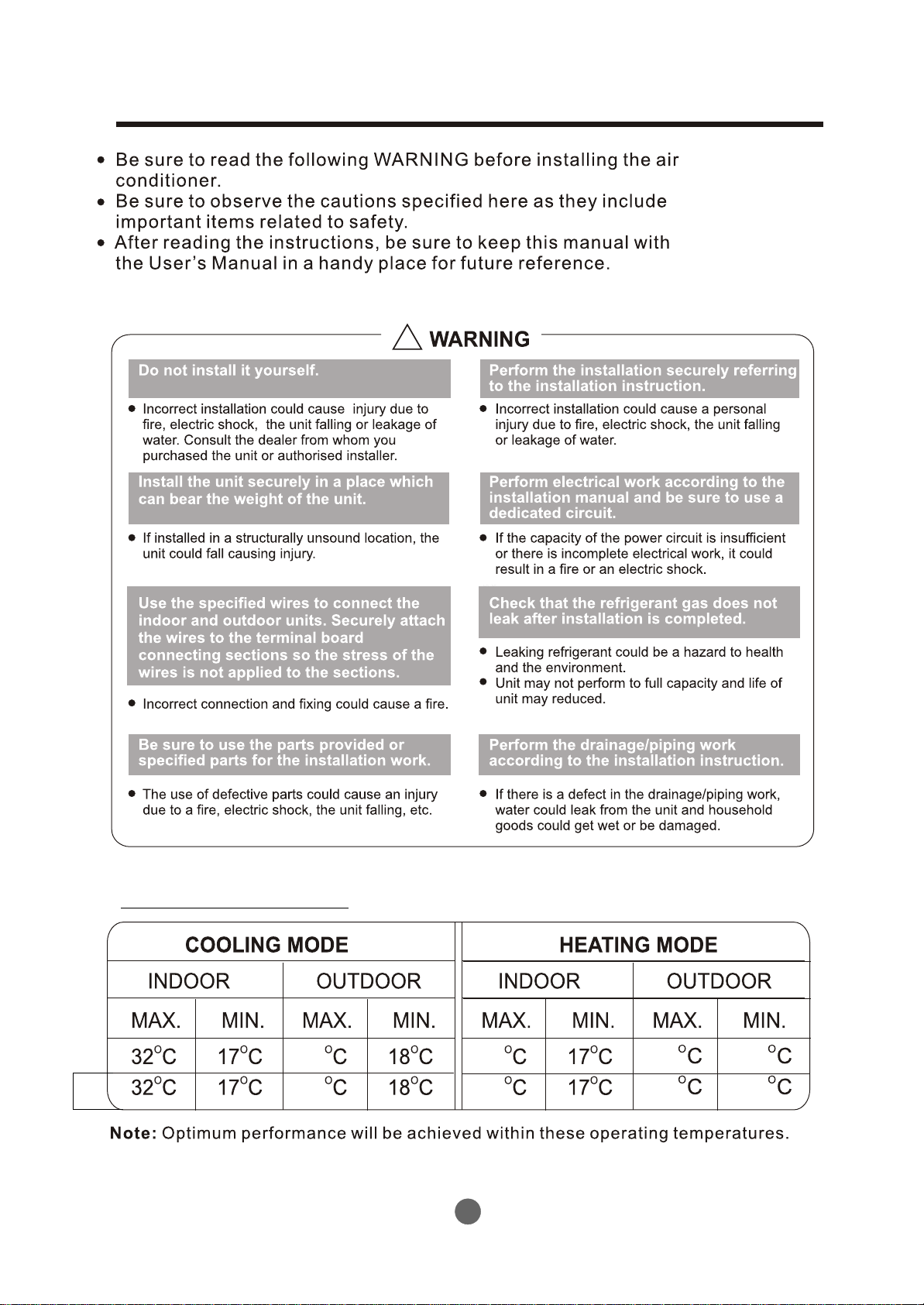
SAFETY PRECAUTIONS
!
OPERATING TEMPERATURE
T3
43
54
2
30
30
24
24
-5
-7
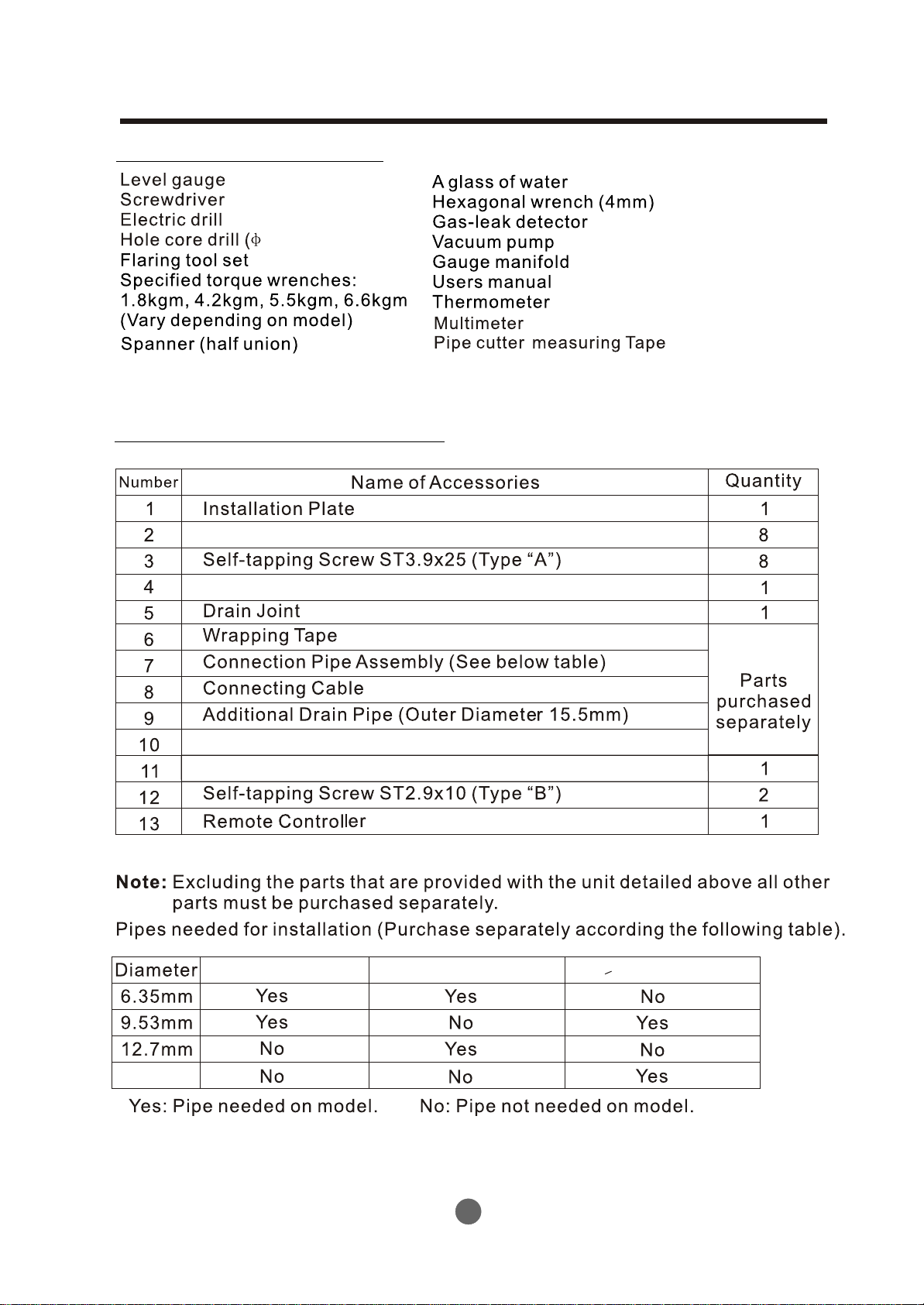
BEFORE INSTALLATION
Tools needed for installation
65mm or 95mm)
Items required for installing the unit
Clip Anchor
Seal (See page 10 for details)
(See page 10 for details)
Insulation materials
Cable Tie (5~10)
7,000 &9,000Btu/h model
12,000 &18,000Btu/h model
>21,000Btu/h model
16.0mm
3
BEFORE INSTALLATION
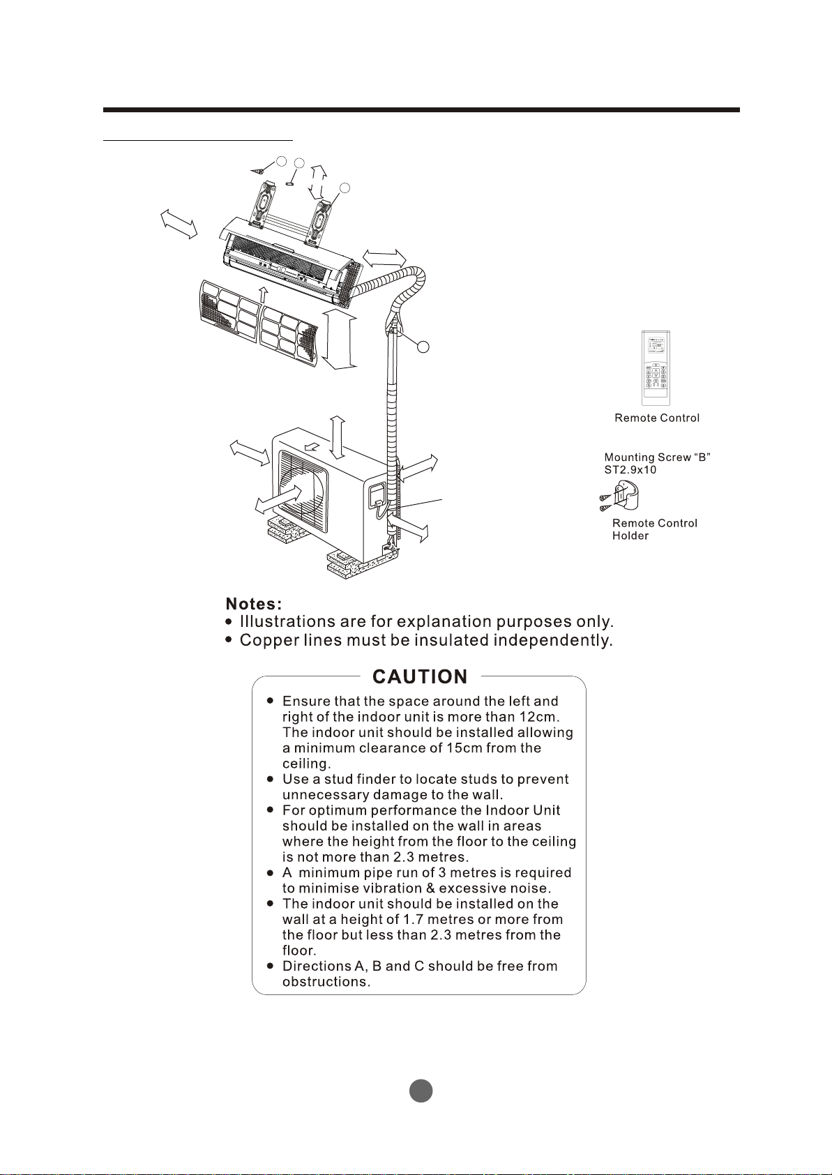
Typical installation
Self-tapping Screw A
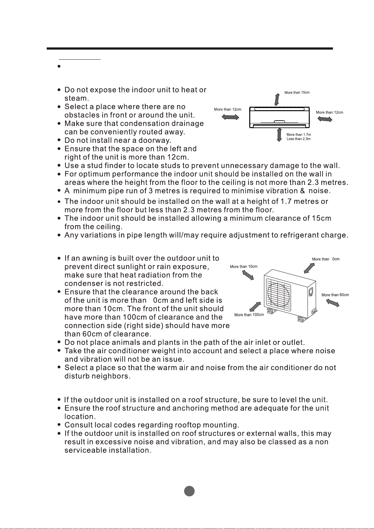
12cm
abo
ve
A
10cm abov
B
e
100cm above
3
Air Filter
2
Air Outlet
Clip Anchor
15cm above
Installation Plate
1
12cm above
m
7
.
.3m
1
2
n
an
ha
h
t
t
ess
L
Mole
ve
bo
a
0cm
6
Connecting
6
pipe Assembly
e
abov
20cm
Loop the
connective
60cm
cable.
above
C
(If applicable)
4
INSTALLATION
Installation
Read completely then follow step by step.
Indoor unit
Fig.1
Outdoor unit
Rooftop installatiom
2
2
Fig.2
5
INSTALLATION
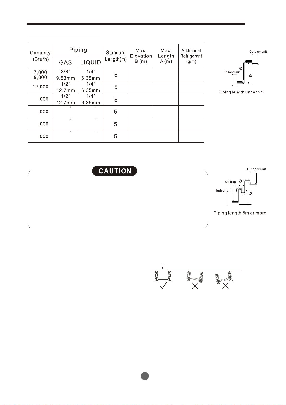
Piping length elevation
8
8
18
21 40
24
30 40
5/8
16.0mm
5/8
16.0mm
5/8
16.0mm
3/8
9.53mm
3/8
9.53mm
3/8
9.53mm
8
10 25
10
10
20
20
20
25
25
15
15
15
40
Capacity is based on standard length and maximum allowance
length is on the basis of reliability.
Oil trap should be installed every 5~7 metres.
When the connecting pipe is longer than 5 metres, additional
refrigerant should be added into the unit according to the
above table through the service port on the “LO” valve on
outdoor unit.
Fig.3
Indoor unit installation
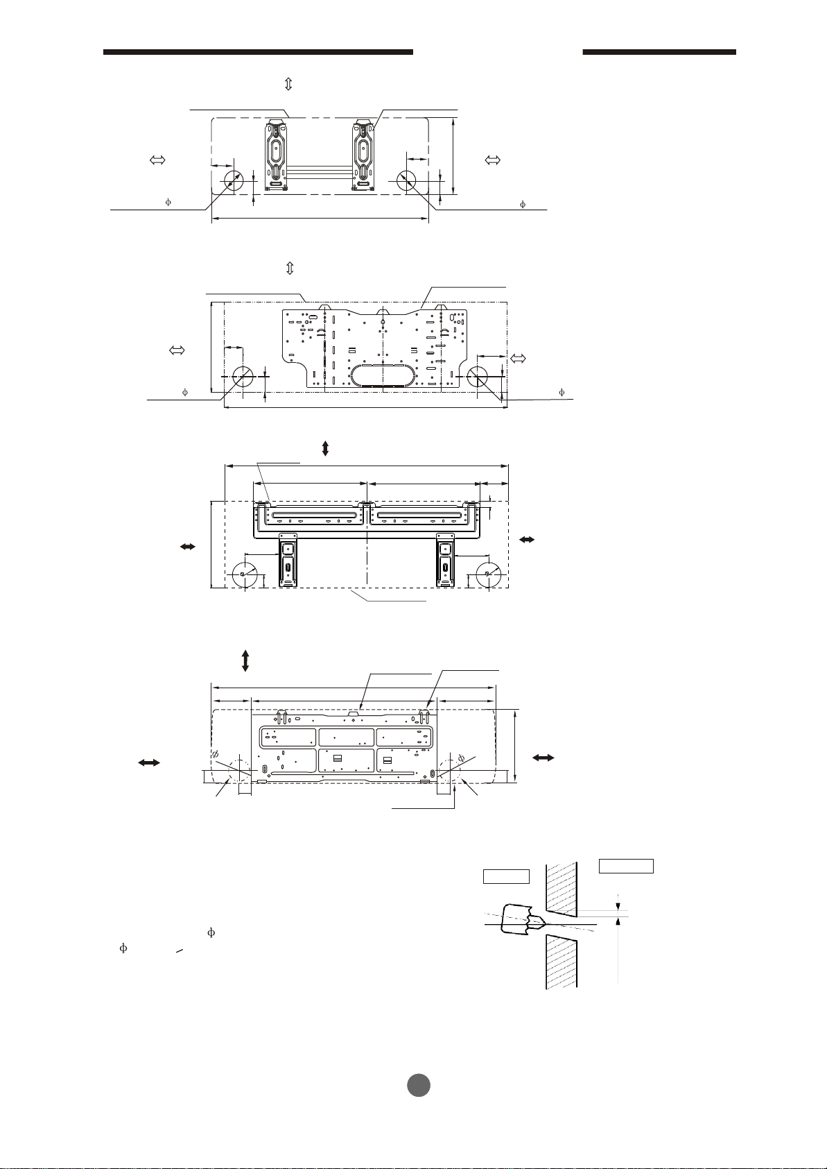
1. Fit the Installation Plate
1). Fit the installation plate horizontally
on structural parts of the wall with
spaces around the installation plate.
2). If the wall is made of brick, concrete or
the like, drill eight (8) 5mm diameter holes
in the wall. Insert Clip anchor for appropriate
mounting screws.
3). Fit the installation plate on the wall with eight
(8) type “A” screws.
Note:
Fit the Installation Plate and drill holes in the wall according to the wall structure and corresponding
mounting points on the installation plate.
(Dimensions are in “mm” unless otherwise stated)
Correct orientation
of Installation Plate
Fig.4
6
INSTALLATION
120mm or more
to wall
Left rear side
refrigerant
pipe hole 65
120mm or more
to wall
Left rear side
refrigerant
pipe hole 65
150mm or more to ceiling
Indoor unit outline
45
40
A
Indoor size:A*B=710*250 or 790*265
150mm or more to ceiling
Indoor unit outline
45
B
45
A
Indoor size:A*B=850*305
Hooked Part
150mm or more from the ceiling
A
380
Installation plate
90
40
Installation plate
380
B
Right rear side
refrigerant
pipe hole 65
120mm or more
to wall
120mm or more
to wall
90
Right rear side
refrigerant
45
pipe hole 65
67
Fig’s 5
120mm or more
from the wall
B
130
65
0
5
Indoor Unit Outline
Indoor size:A*B=998*322
Above 150 from
the ceiling
Hooked Part
A
178
815
Above 120 from
the wall
95
55
Pipe hole
58
Indo
Indoor size:A*B=1250*325
2. Drill a hole in the wall
1. Determine hole positions according to
the diagram detailed in Fig.5. Drill
one (1) hole ( 65mm <998*322 or
95mm >1250*325) slanting slightly
to outdoor side.
2. Always use wall hole conduit when
drilling metal grid, metal plate or the like.
22
120mm or more
from the wall
130
65
0
5
Hooker Part
257
Above 120 from
B
55
ip
e ho
Indoor
the wall
le
Wall
Outdoor
5-7mm
95
55
or
u
ni
t o
utlin
P
e
Fig.6
7
 Loading...