

AEG-Electrolux ESER21PSAMB, ESCR21PSAMB, EXS24HE2WI, EXS09HC7, EXS12HC1WE User Manual
...
Website: www.mideaaircon.com
Service manual
CAUTION
- BEFORE SERVICING THE UNIT, READ THE SAFETY
- PRECAUTIONS IN THIS MANUAL.
- ONLY FOR AUTHORIZED SERVICE PERSONNEL.
MODELS:
EL-KF20GW/N2Y-A(B) EL-KFR20GW/N2Y-A(B) EL-KF26GW/N2Y-A(B) EL-KFR26GW/N2Y-A(B)
EL-KF36GW/N2Y-A(B) EL-KFR36GW/N2Y-A(B) EL-KF50GW/N2Y-A(B) EL-KFR50GW/N2Y-A(B)
EL-KF61GW/N2Y-A(B) EL-KFR61GW/N2Y-A(B) EL-KF70GW/N2Y-A(B) EL-KFR70GW/N2Y-A(B)
EL-KFR20GW/N1Y-A(B) EL-KFR26GW/N1Y-A(B) EL-KFR36GW/N1Y-A(B)
EL-KF20GW/Y-A(B) EL-KFR20GW/Y-A(B) EL-KF26GW/Y-A(B) EL-KFR26GW/Y-A(B)
EL-KF32GW/Y-A(B) EL-KFR32GW/Y-A(B) EL-KF36GW/Y-A(B) EL-KFR36GW/Y-A(B)
EL-KF50GW/Y-A(B) EL-KFR50GW/Y-A(B) EL-KF61GW/Y-A(B) EL-KFR61GW/Y-A(B)
EL-KF70GW/Y-A(B) EL-KFR70GW/Y-A(B) EL-KF90GW/Y-A(B) EL-KFR90GW/Y-A(B)
EL-KF90GW/SY-A(B) EL-KFR90GW/SY-A(B) AU-KF61GW/Y-A(B) AU-KFR61GW/Y-A(B)
AU-KF70GW/Y-A(B) AU-KFR70GW/Y-A(B) AU-KF85GW/Y-A(B) AU-KFR85GW/Y-A(B)
EL1-KF20GW/Y-A(B) EL1-KFR20GW/Y-A(B) EL1-KF26GW/Y-A(B) EL1-KFR26GW/Y-A(B)
EL1-KF32GW/Y-A(B) EL1-KFR32GW/Y-A(B) EL1-KF20GW/N2Y-A(B) EL1-KFR20GW/N2Y-A(B)
EL1-KF26GW/N2Y-A(B) EL1-KFR26GW/N2Y-A(B) EL1-KF35GW/N2Y-A(B) EL1-KFR35GW/N2Y-A(B)
EL-KT3F53GW/Y-T2 EL-KT3F53GW/Y-T1 EL-KT3FR53GW/Y-T1
EL-KT3F70GW/Y-T2 EL-KT3F70GW/Y-T1 EL-KT3FR70GW/Y-T1
SEL-KF20GW/Y-A(B) SEL-KFR20GW/Y-A(B) SEL-KF26GW/Y-A(B) SEL-KFR26GW/Y-A(B)
SEL-KF32GW/Y-A(B) SEL-KFR32GW/Y-A(B) SEL-KF53GW/Y-A(B) SEL-KFR53GW/Y-A(B)
SEL-KF61GW/Y-A(B) SEL-KFR61GW/Y-A(B) SEL-KF70GW/Y-A(B) SEL-KFR70GW/Y-A(B)
SEL1-KF26GW/Y-A(B) SEL1-KFR26GW/Y-A(B) SEL1-KF36GW/Y-A(B) SEL1-KFR36GW/Y-A(B)
0

GD Midea Refrigerant Equipment Co. Ltd Service manual for Electrolux split Series
CONTENTS
1. PREFACE
1.1 SAFETY PRECAUTIONS........................................................................................................................1
1.2 INSULATION RESISTANCE TEST.........................................................................................................1
1.3 FEATURES...............................................................................................................................................2
1.4 CONTROL LOCATIONS.............................................................................................................................2
1.5 OUTSIDE DIMENSIONS............................................................................................................................3
2. INSTALLATION
2.1 TOOLS NEEDED FOR INSTALLATION....................................................................................................5
2.2 ITEMS REQUIRED FOR INSTALLING THE UNIT........................................ ............................................5
2.3 INSTALLATION OF INDOOR UNIT AND OUTDOOR UNIT ................................................................... ..6
2.4 FLARING WORK AND CONNECTION OF PIPING.................................................... ...............................8
2.5 CONNECTING THE CABLE BETWEEN INDOOR UNIT AND OUTDOOR UNIT……………..................12
2.6 CHECKING THE DRAINAGE AND FORMING THE PIPING ................................................ ....... ... ....... . .14
2.7 AIR PURGING.......................................... .................................................. ...............................................15
2.8 TEST RUNNING ............................................. ...................... ...................... ..............................................17
3. TROUBLE SHOOTING GUIDE
3.1 Refrigeration Cycle Diagram..................................... ................................................................................19
3.2 TROUBLE SHOOTING GUIDE..................................................................................................................20
4. WIRING DIAGRAM
4.1 Wiring diagram for indoor units……..........................................................................................................26
4.2 Wiring diagram for outdoor units...............................................................................................................32
5. EXPLODED VIEWS…………………………………………...........................................................................40
6 SPECIFICATIONS........................................................................................................................................40
7 SPARE PARTS LIST……………………………………………………..………….……………………………..40
8 MODEL CHECK LIST……………………………………………………………………………………………….40
1. PREFACE
This SERVICE MANUAL provides various servicing information, including the mechanical and electrical parts,
etc. This room air conditioner was manufactured and assembled under a strict quality control system.
The refrigerant is charged at the factory. Be sure to read the safety precautions prior to servicing the unit.
1.1 SAFETY PRECAUTIONS
1. When servicing the unit, set the POWER SWITCH to OFF and unplug the power cord.
2. Inspect the service cord for damage or wear.
If a short circuit is found, replace all parts which have been overheated or damaged by the short circuit.
3. After servicing the unit, make an insulation resistance test to protect the customer from being exposed to
shock hazards.
1.2 INSULATION RESISTANCE TEST
1. Unplug the power cord and connect a jumper lead between the two (2) live pins.
2. The grounding conductor (yellow/green) is to be open.
3. Measure the resistance value with an ohm meter between the jumped lead and each exposed metallic part
on the equipment at all the positions (except OFF) of the ROTARY SWITCH or POWER SWITCH.
4. The value should be over 1MΩ.
1
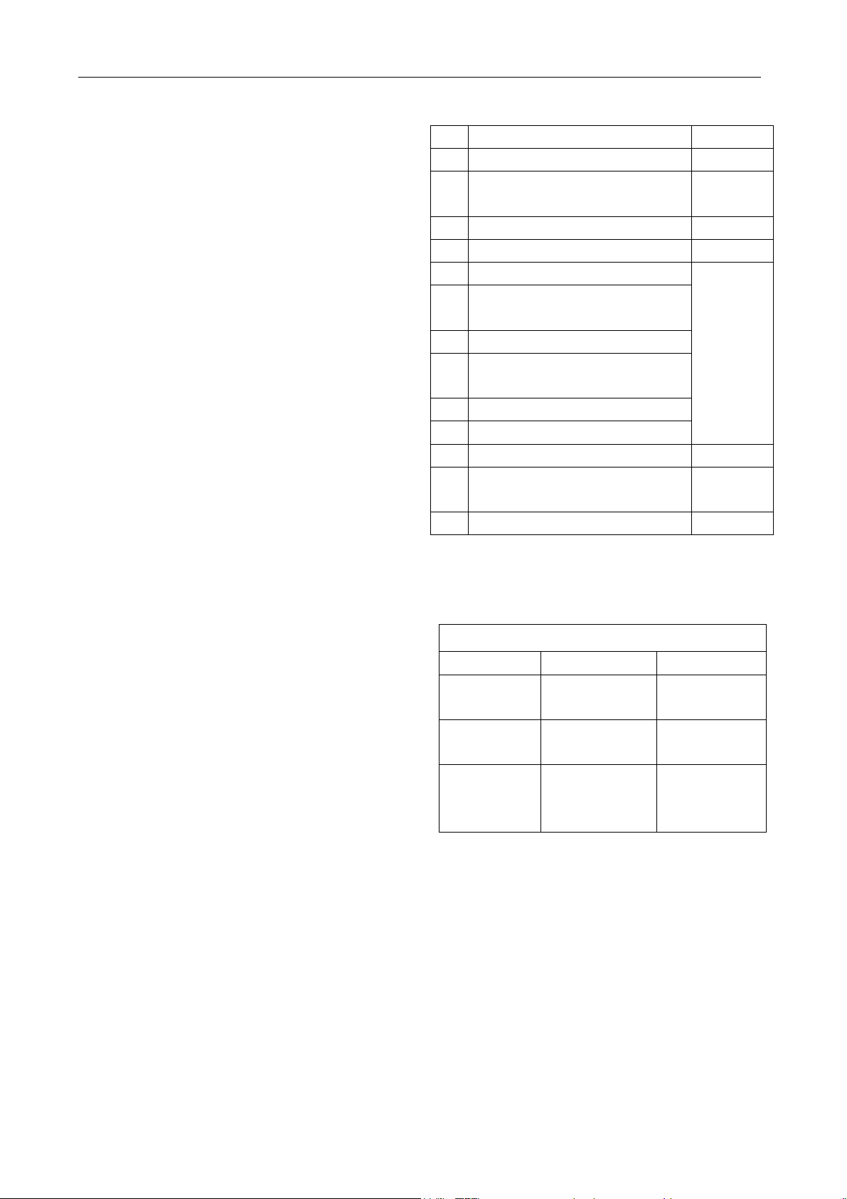
1.3 FEATURES
Error self diagnosis function.
Anti-icing function at cooling mode.
Anti-cold air function at heating mode.
Auto-defrosting and heating recovering function
at heating mode.
Outdoor unit overload current protection.
Temperature protection of the outdoor
compressor top.
Restart protection for the compressor.
24 hours on/off mode time setting.
Protection against over-load or too-low current
input through alternating current.
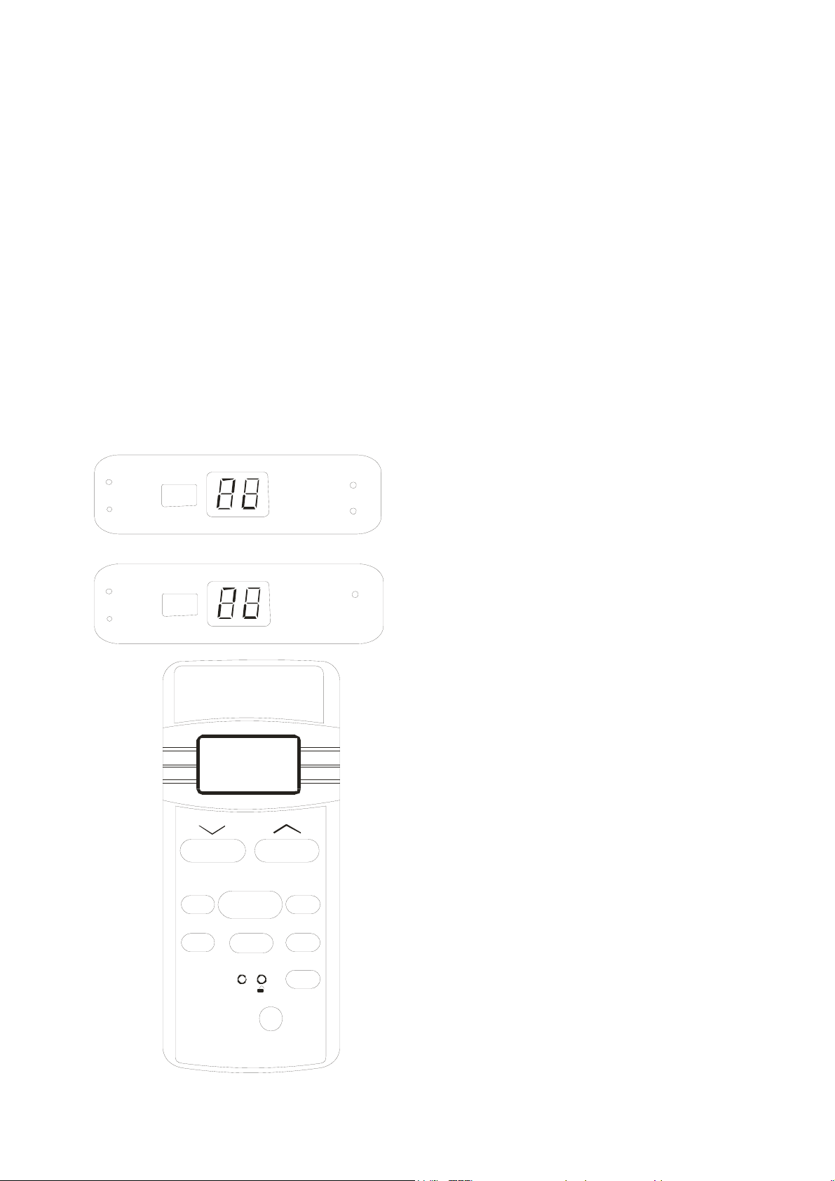
1.4 CONTROL LOCATIONS
For reverse cycle models:
R
M
E
I
T
℃
O
T
A
U
R
E
W
O
P
T
S
O
R
F
E
D
For cooling only models:
R
E
M
I
T
℃
O
T
A
U
AUTO
COOL
DRY
HEAT
TEMP
MODE ON/OFF
SWING ECONOM Y
RESET
R
DIGITAL DISPLAY
LOCK
TIME R
CANCEL
FAN
O
P
FAN
HIGH
MED
LOW
R
E
W
LED lamp:
POWER
AUTO
TIMER
DEFROST
Remote controller:
LCD display
Mode button: Select the operation mode, AUTO,
COOL, DRY, HEAT (Reverse cycle
models only) and F AN.
Fan speed button: Select the Fan speed, AUTO,
LOW, MED, HIGH.
ON/OFF button: Press this button to operation
the unit, again to stop.
Temperature setting up button: Press this
button to increase temperature
setting or adjust the TIMER in a
clockwise direction.
Temperature setting down button: Press this
button to decrease temperature
setting or adjust the TIMER in a
counter-clockwise direction.
Swing button: Press this button to activate the
auto swing, again to stop.
Economy button: Push this button to set the
economical operation mode.
Timer button: Press this button to set TIMER
ON and/or TIMER OFF.
Cancel button: Press this button to cancel
TIMER ON and TIMER OFF.
Lock button: Press this button to lock all button
except this button.
Reset button: Press this button to reset all
settings to original.
Digital display button: Press this button to
activate/eliminate the digital
temperature display on the indoor
unit.
2
GD Midea Refrigerant Equipment Co. Ltd Service manual for Electrolux split Series
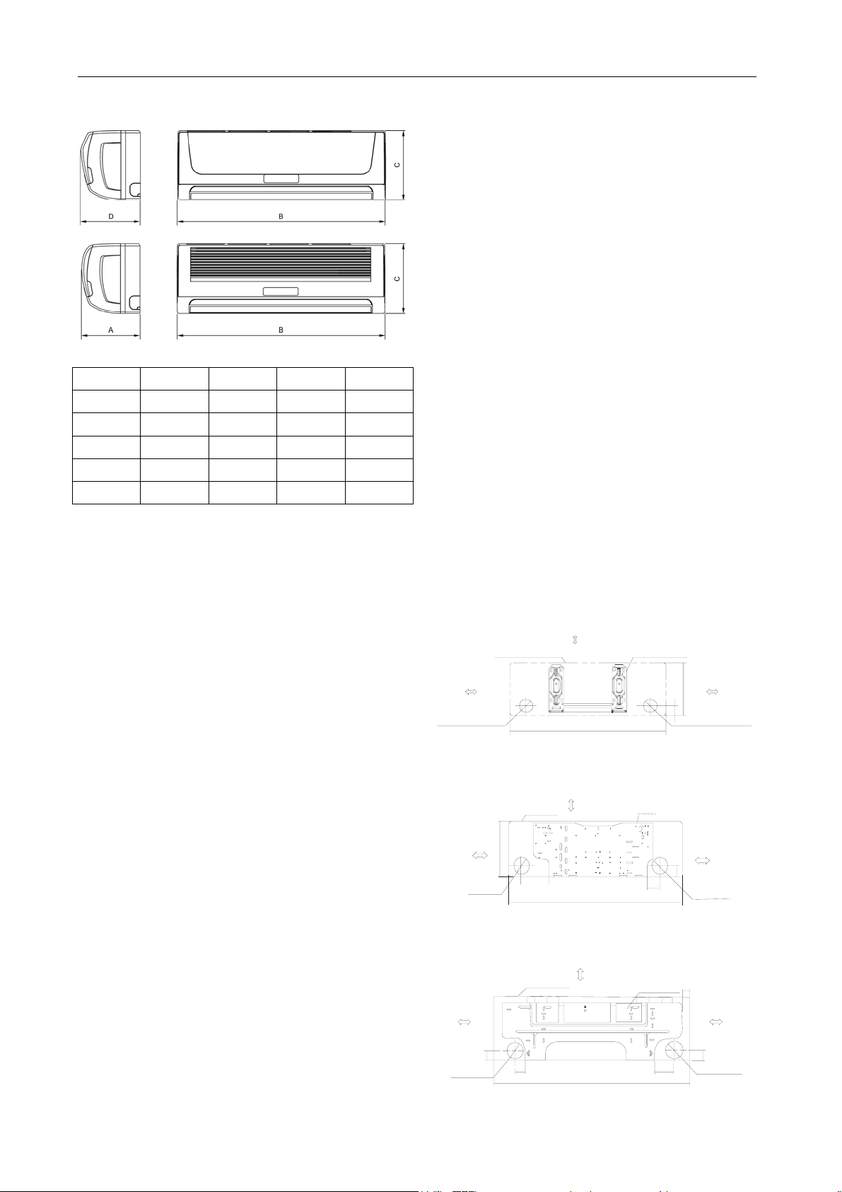
1.5 OUTSIDE DIMENSIONS
1.5.1 Indoor units:
A: width (mm) B: Depth (mm) C: Height (mm)
Unit A(mm) B(mm) C(mm) D(mm)
Size A 210 750 250 214
Size B 213 815 282 217
Size C 228 1000 298 232
Size D 240 1080 330 245
Size E 230 1250 325 230
Model list:
Size A indoor units:
EL-KF20GW/N2Y-A(B) EL-KFR20GW/N2Y-A(B)
EL-KF26GW/N2Y-A(B) EL-KFR26GW/N2Y-A(B)
EL-KFR20GW/N1Y-A(B) EL-KFR26GW/N1Y-A(B)
EL-KF20GW/Y-A(B) EL-KFR20GW/Y-A(B)
EL-KF26GW/Y-A(B) EL-KFR26GW/Y-A(B)
EL-KF32GW/Y-A(B) EL-KFR32GW/Y-A(B)
EL1-KF20GW/Y-A(B) EL1-KFR20GW/Y-A(B)
EL1-KF26GW/Y-A(B) EL1-KFR26GW/Y-A(B)
EL1-KF32GW/Y-A(B) EL1-KFR32GW/Y-A(B)
EL1-KF20GW/N2Y-A(B) EL1-KFR20GW/N2Y-A(B)
EL1-KF26GW/N2Y-A(B) EL1-KFR26GW/N2Y-A(B)
SEL-KF20GW/Y-A(B) SEL-KFR20GW/Y-A(B)
SEL-KF26GW/Y-A(B) SEL-KFR26GW/Y-A(B)
SEL-KF32GW/Y-A(B) SEL-KFR32GW/Y-A(B)
SEL1-KF26GW/Y-A(B) SEL1-KFR26GW/Y-A(B)
Size B indoor units:
EL-KF36GW/N2Y-A(B) EL-KFR36GW/N2Y-A(B)
EL-KFR36GW/N1Y-A(B)
EL-KF36GW/Y-A(B) EL-KFR36GW/Y-A(B)
EL1-KF35GW/N2Y-A(B) EL1-KFR35GW/N2Y-A(B)
SEL1-KF36GW/Y-A(B) SEL1-KFR36GW/Y-A(B)
Size C indoor units:
EL-KF50GW/N2Y-A(B) EL-KFR50GW/N2Y-A(B)
EL-KF50GW/Y-A(B) EL-KFR50GW/Y-A(B)
EL-KT3F53GW/Y-T2
EL-KT3F53GW/Y-T1 EL-KT3FR53GW/Y-T1
SEL-KF53GW/Y-A(B) SEL-KFR53GW/Y-A(B)
Size D indoor units:
EL-KF61GW/N2Y-A(B) EL-KFR61GW/N2Y-A(B)
EL-KF70GW/N2Y-A(B) EL-KFR70GW/N2Y-A(B)
EL-KF61GW/Y-A(B) EL-KFR61GW/Y-A(B)
EL-KF70GW/Y-A(B) EL-KFR70GW/Y-A(B)
AU-KF61GW/Y-A(B) AU-KFR61GW/Y-A(B)
AU-KF70GW/Y-A(B) AU-KFR70GW/Y-A(B)
EL-KT3F70GW/Y-T2
EL-KT3F70GW/Y-T1 EL-KT3FR70GW/Y-T1
SEL-KF61GW/Y-A(B) SEL-KFR61GW/Y-A(B)
SEL-KF70GW/Y-A(B) SEL-KFR70GW/Y-A(B)
Size E indoor units:
EL-KF90GW/Y-A(B) EL-KFR90GW/Y-A(B)
EL-KF90GW/SY-A(B) EL-KFR90GW/SY-A(B)
AU-KF85GW/Y-A(B) AU-KFR85GW/Y-A(B)
1.5.2 Installation plate
For Size A indoor unit:
120mm or m ore
to wal l
Left refrigerant
pipe ho le D65
Indoor unit outline
150mm or more to ceiling
750
Installation plate
45
250
Right refrigerant
pipe hole D65
For Size B indoor unit:
120mm or more
to wal l
Left refrigerant
pipe hole D65
Indoor unit outline
150mm or more to ceiling
280
815
Installation plate
50
50
Right refriger ant
pipe hole D 6 5
For Size C indoor unit:
150mm or more to the ceiling
Installation plate
1000
49
120mm or more
to the wal l
50
90
3
120mm or more
to the wa ll
Left pipe
hole D65
Indoor unit outl ine
50
55
120mm or more
to wall
120mm o r more
to wal l
Rig h t pi pe
hole D 65
GD Midea Refrigerant Equipment Co. Ltd Service manual for Electrolux split Series
For Size D indoor unit:
Hooked Part
432
120mm o r more to
the wall
58
50
Left Pipe
hol e D95
115
465
For Size E indoor unit:
Ho oke d Par t
178
120mm or more
to the wall
55
Left pipe
hole D95
58
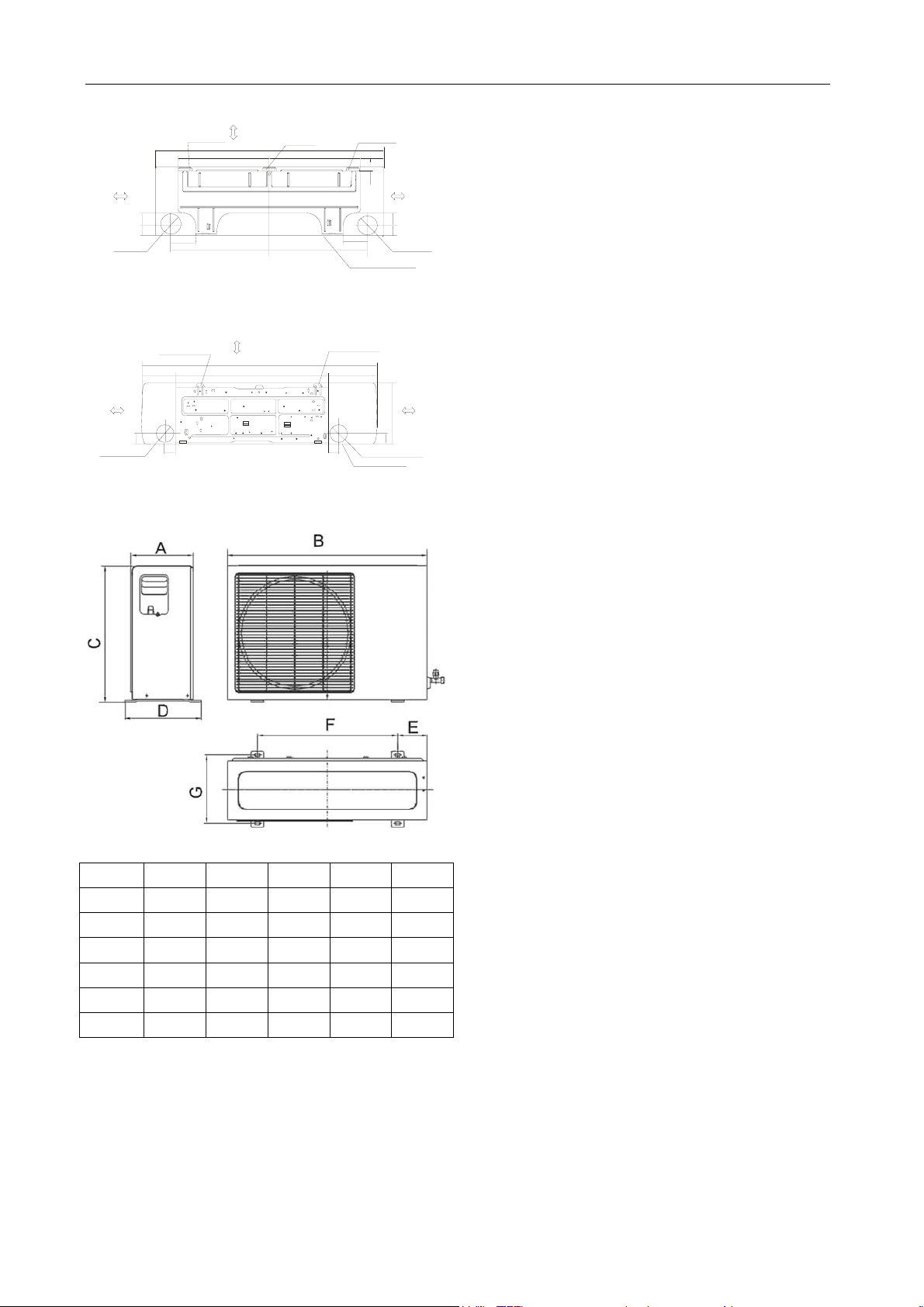
1.5.3 Outdoor units:
150 or more to the ceiling
Hooked Part
1080
150mm or mo re to the ceiling
1250
815
Hooked Part
432
465
Hooker Part
55
108
22
115
Indoor Unit Outline
257
R
g
i
h
t
I
n
d
o
o
r
u
n
120mm or more to
the wall
5850
Rig h t p ipe
hole D95
120mm or more
to the wa l l
325
55
p
i
p
e
h
o
e
D
9
l
5
t
o
e
u
l
t
n
i
i
EL1-KF20GW/Y-A(B) EL1-KFR20GW/Y-A(B)
EL1-KF26GW/Y-A(B) EL1-KFR26GW/Y-A(B)
EL1-KF20GW/N2Y-A(B) EL1-KFR20GW/N2Y-A(B)
EL1-KF26GW/N2Y-A(B) EL1-KFR26GW/N2Y-A(B)
SEL-KF20GW/Y-A(B) SEL-KFR20GW/Y-A(B)
SEL-KF26GW/Y-A(B) SEL-KFR26GW/Y-A(B)
Size G outdoor units:
EL-KFR26GW/N1Y-A(B) EL-KFR36GW/N1Y-A(B)
EL-KF32GW/Y-A(B) EL-KFR32GW/Y-A(B)
EL-KF36GW/Y-A(B) EL-KFR36GW/Y-A(B)
EL1-KF32GW/Y-A(B) EL1-KFR32GW/Y-A(B)
EL1-KF35GW/N2Y-A(B) EL1-KFR35GW/N2Y-A(B)
SEL-KF32GW/Y-A(B) SEL-KFR32GW/Y-A(B)
SEL1-KF26GW/Y-A(B) SEL1-KFR26GW/Y-A(B)
Size H outdoor units:
EL-KF36GW/N2Y-A(B) EL-KFR36GW/N2Y-A(B)
SEL1-KF36GW/Y-A(B) SEL1-KFR36GW/Y-A(B)
Size I outdoor units:
EL-KF50GW/N2Y-A(B) EL-KFR50GW/N2Y-A(B)
EL-KF61GW/N2Y-A(B) EL-KFR61GW/N2Y-A(B)
EL-KF70GW/N2Y-A(B) EL-KFR70GW/N2Y-A(B)
EL-KF50GW/Y-A(B) EL-KFR50GW/Y-A(B)
EL-KF61GW/Y-A(B) EL-KFR61GW/Y-A(B)
EL-KF70GW/Y-A(B) EL-KFR70GW/Y-A(B)
AU-KF61GW/Y-A(B) AU-KFR61GW/Y-A(B)
AU-KF70GW/Y-A(B) AU-KFR70GW/Y-A(B)
EL-KT3F53GW/Y-T2
EL-KT3F53GW/Y-T1 EL-KT3FR53GW/Y-T1
EL-KT3F70GW/Y-T1 EL-KT3FR70GW/Y-T1
SEL-KF53GW/Y-A(B) SEL-KFR53GW/Y-A(B)
SEL-KF61GW/Y-A(B) SEL-KFR61GW/Y-A(B)
A: Depth (mm) B: Width (mm) C: Height (mm)
Unit Size F Size G Size H Size I Size J
A(mm) 235 250 285 335 330
B(mm) 700 780 760 845 895
C(mm) 535 540 590 695 860
D(mm) 275 298 315 360 355
E(mm) 120 114.5 110 140 141.3
F(mm) 458 549 530 560 589.6
Size F outdoor units:
EL-KF20GW/N2Y-A(B) EL-KFR20GW/N2Y-A(B)
EL-KF26GW/N2Y-A(B) EL-KFR26GW/N2Y-A(B)
EL-KFR20GW/N1Y-A(B)
EL-KF20GW/Y-A(B) EL-KFR20GW/Y-A(B)
EL-KF26GW/Y-A(B) EL-KFR26GW/Y-A(B)
SEL-KF70GW/Y-A(B) SEL-KFR70GW/Y-A(B)
Size J outdoor units:
EL-KF90GW/Y-A(B) EL-KFR90GW/Y-A(B)
EL-KF90GW/SY-A(B) EL-KFR90GW/SY-A(B)
AU-KF85GW/Y-A(B) AU-KFR85GW/Y-A(B)
EL-KT3F70GW/Y-T2
4
GD Midea Refrigerant Equipment Co. Ltd Service manual for Electrolux split Series
2 INSTALLATION
2.1 TOOLS NEEDED FOR INSTALLATION
Level gauge
Screwdriver
Electric drill
Hole core drill ( φ85mm or φ115mm depending
on Model)
Flaring tool set
Specified torque wrenches: 1.8kgm, 4.2kgm,
5.5kgm, 6.6kgm (Vary depending on model
No.)
Spanner (half union)
A glass of water
Hexagonal wrench (4mm)
Gas-leak detector
Vacuum pump
Gauge manifold
User’s manual
Thermometer
2.2 ITEMS REQUIRED FOR INSTALLING THE
UNIT
No. Name of Accessories Quantity
1 Installation Plate 1
2 Self-tapping Screw ST3.9x25
8
(Type “A”)
3 Plastic Expansion Sheath 8
4 Drain Joint 1
5 Wrapping Tape
6 Connection Pipe Assembly
(Detail in below table)
7 Connecting Cable
8 Additional Drain Pipe (Outer
Parts
purchased
separately
Diameter15.5mm)
9 Insulation Materials
10 Cable Tie (5~10)
11 Remote Control Holder 1
12 Self-tapping Screw ST2.9x10
2
(Type “B”)
13 Remote Control 1
Note: Excluding the parts that are provided with
the unit detailed above all other parts must be
purchased separately.
Connection Pipe Assembly
model Liquid side pipe Gas side pipe
7,000Btu/h
9,000Btu/h
12,000Btu/h
18,000Btu/h
21,000Btu/h
24,000Btu/h
6.35mm
1/4”
6.35mm
1/4”
9.53mm
3/8”
9.53mm
3/8”
12.7mm
1/2”
16mm
5/8”
30,000Btu/h
NOTE: For pipes used on R410A system, the
wall thickness of the pipes should be
no less than 0.7mm. Otherwise, the
pipes may be broken when using.
5
GD Midea Refrigerant Equipment Co. Ltd Service manual for Electrolux split Series
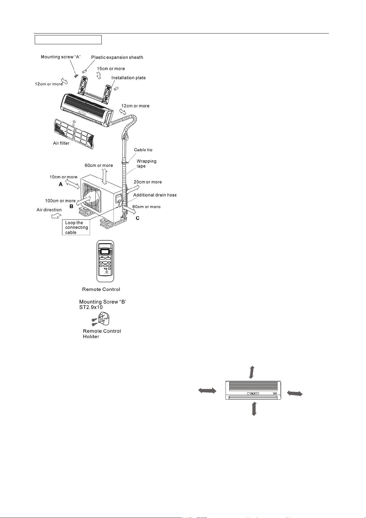
Typical installation
CAUTIONS:
1. Ensure that the space around the left and
right of the indoor unit is more than 12cm.
2. The indoor unit should be installed allowing a
minimum clearance of 15cm from the ceiling.
3. Use a stud finder to locate studs to prevent
unnecessary damage to the wall.
4. For optimum performance the Indoor Unit
should be installed on the wall in areas where
the height from the floor to the ceiling is not
more than 2.3 meters.
5. A minimum pipe run of 3 meters is required to
minimize vibration & excessive noise.
6. The indoor unit should be installed on the wall
at a height of 1.7 meters or more from the
floor but less than 2.3 meters from the floor.
7. Directions A, B and C should be free from
obstructions.
2.3 INSTALLATION OF INDOOR UNIT AND
OUTDOOR
2.3.1 Indoor unit
● Do not expose the indoor unit to heat or
steam.
● Select a place where there are no obstacles in
front or around the unit.
● Make sure that condensation drainage can be
conveniently routed away.
● Do not install near a doorway.
● Ensure that the space on the left and right of
the unit is more than 12cm.
● Use a stud finder to locate studs to prevent
unnecessary damage to the wall.
● For optimum performance the indoor unit
should be installed on the wall in areas where the
height from the floor to the ceiling is not more than
2.3 meters.
● A minimum pipe run of 3 meters is required to
minimize vibration & excessive noise.
● The indoor unit should be installed on the wall
at a height of 1.7 meters or more from the floor but
less than 2.3 meters from the floor.
● The indoor unit should be installed allowing a
minimum clearance of 15cm from the ceiling.
● Any variations in pipe length will/may require
adjustment to refrigerant charge (Refer to item
2.3.3).
m
c
5
1
n
a
h
t
r
e
Mo
More than 12cm
M
o
s
e
L
r
e
t
h
a
s
n
t
a
h
More than 12cm
n
.
1
m
7
.
2
m
3
2.3.2 Outdoor unit
● If an awning is built over the outdoor unit to
prevent direct sunlight or rain exposure, make
sure that heat radiation from the condenser is not
restricted.
6
GD Midea Refrigerant Equipment Co. Ltd Service manual for Electrolux split Series
2
0
● Ensure that the clearance around the back of
the unit is more than 20cm and left side is more
than 10cm.
● The front of the unit should have more than
100cm of clearance and the connection side (right
side) should have more than 60cm of clearance.
● Do not place animals and plants in the path of
the air inlet or outlet.
● Take the air conditioner weight into account
and select a place where noise and vibration will
not be an issue.
● Select a place so that the warm air and noise
from the air conditioner do not disturb neighbors.
m
c
n
h
a
t
e
r
Mo
m
0
c
1
n
h
a
t
e
r
Mo
GAS
Piping
LIQUID
3/8”
9.53mm
1/4”
6.35mm
Standard Length(m) 5 5 5
Max. Elevation B (m) 5 5 5
Max. Length A (m) 10 10 10
Additional
Refrigerant (g/m)
30 30 65
Cautions:
● Capacity is based on standard length and
maximum allowance length is on the basis of
reliability.
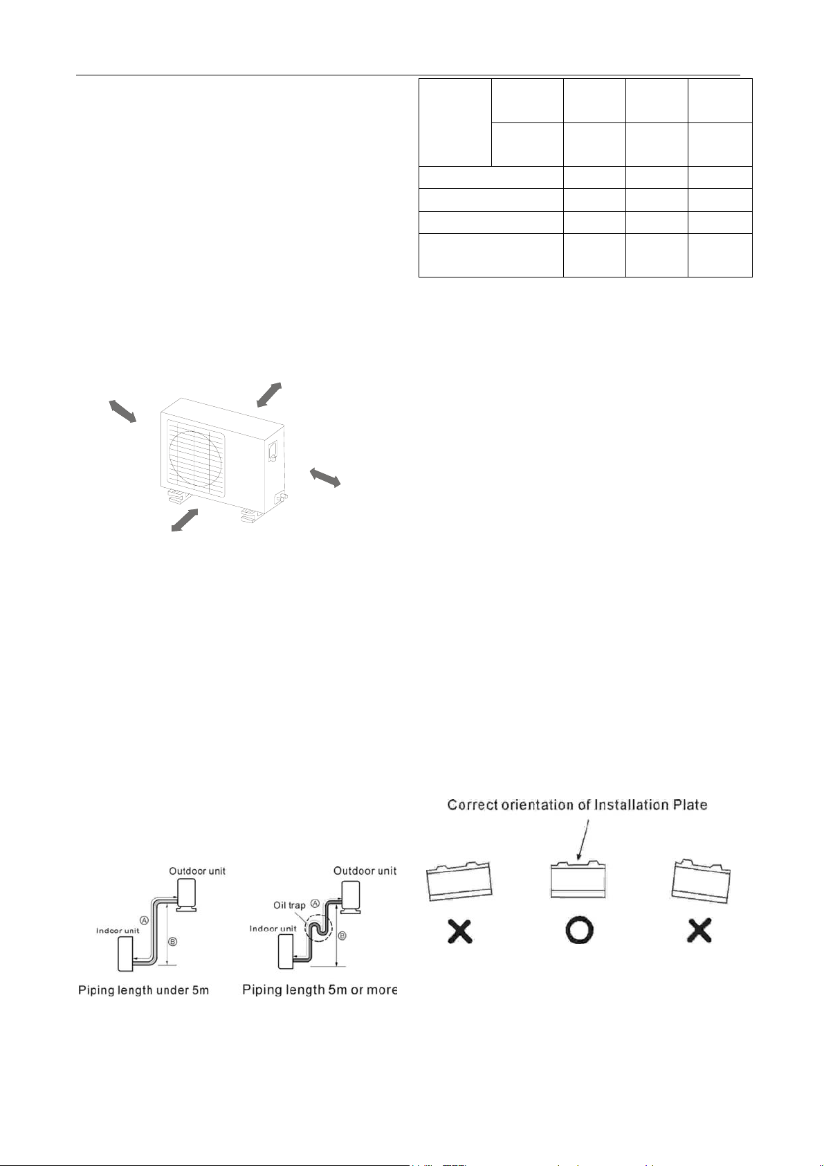
● Oil trap should be installed every 5~7 meters.
● When the connecting pipe is longer than 5
1/2”
12.7mm
1/4”
6.35mm
5/8”
16.0mm
3/8”
9.53mm
meters, Additional refrigerant should be added
into the unit according to the above table through
Mo
the service port on the “LO” valve on outdoor unit.
c
m
0
6
n
a
h
t
e
r
2.3.4 Fitting the installation plate
Fit the Installation Plate and drill holes in the wall
M
Rooftop installation:
● If the outdoor unit is installed on a roof
structure, be sure to level the unit.
● Ensure the roof structure and anchoring
method are adequate for the unit location.
● Consult local codes regarding to rooftop
mounting.
● If the outdoor unit is installed on roof
structures or external walls, this may result in
excessive noise and vibration, and may also be
according to the wall structure and corresponding
mounting points on the installation plate.
1. Fit the installation plate horizontally on
structural parts of the wall with spaces around the
installation plate (Detailed on page 3 as
applicable).
2. If the wall is made of brick, concrete or the like,
drill eight (8) 5mm diameter holes in the wall.
Insert Plastic Expansion Sheath for appropriate
mounting screws.
3. Fit the installation plate on the wall with eight (8)
type “A” screws.
m
0
c
0
1
t
h
an
e
r
o
classed as a non serviceable installation.
2.3.3 Piping length and elevation
2.3.5 Drill a hole in the wall
1. Determine hole positions according to the
diagram detailed on page 3 as applicable. Drill
one (1) hole (φ85mm for those models need
φ65mm pipe hole or φ115mm for models need
φ95mm pipe hole) slanting slightly to outdoor
7
GD Midea Refrigerant Equipment Co. Ltd Service manual for Electrolux split Series
side.
2. Always use wall hole
conduit when drilling
metal grid, metal plate
or the like.
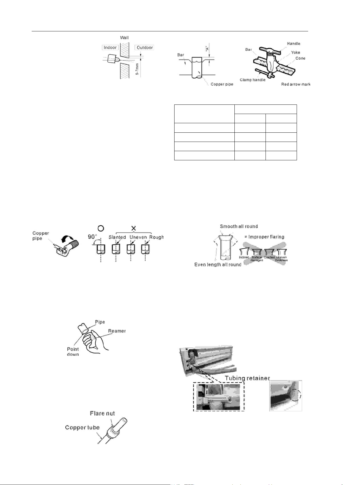
2.4 FLARING WORK AND CONNECTION OF
PIPING
The main cause for gas leakage is due to defects
in flaring work. Carry out correct flaring work using
the following procedure.
2.4.1 Flaring work
2.4.1.1 Cut the pipes and the cable.
● Use the piping kit accessory (if applicable) or
the pipes purchased locally.
● Measure the distance between the indoor and
the outdoor unit.
● Cut the pipes a little longer than measured
distance.
● Cut the cable 1.5m longer than the pipe
length.
2.4.1.4 Flaring work
● Carry out flaring work using flaring tool as
shown below.
Out diameter
“A” (mm)
Max. Min.
1/4” (6.35mm) 1.3 0.7
3/8” (9.53mm) 1.6 1.0
1/2” (12.7mm) 1.8 1.0
5/8” (16.0mm) 2.4 1.8
Hold copper pipe firmly in a die according to the
dimension shown in the table above.
2.4.1.5 Check
● Compare the flared work with the adjacent
diagram.
● If flare is found to be defective, cut off the
flared section and do flaring work again.
2.4.1.2 Burrs removal
● Completely remove all burrs from the cut cross
section of pipe/tube.
● Place the end of the copper tube/pipe in a
downward direction as you remove burrs in order
to avoid dropping burrs into the tubing.
2.4.1.3 Putting flare nut on
● Remove flare nuts attached to indoor and
outdoor unit, then put them on pipe/tube having
completed burr removal.
(Note: It is not possible to put them on after flaring
work.)
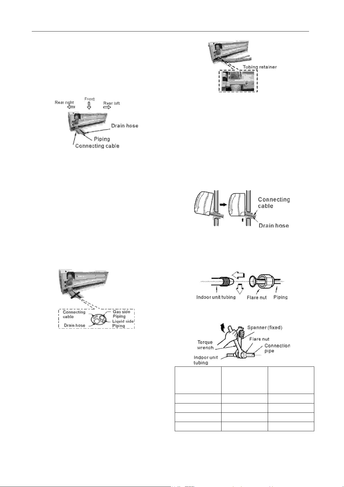
2.4.2 Connection of pipes - Indoor
● Prepare the indoor unit’s pipi ng and drain ho se
for installation through the wall.
● Remove the tubing retainer (see illustration
right) and pull the tubing and drain hose away
from chassis (If required). For some models thi s is
not needed.
Replace the tubing retainer in its original position.
CAUTION
When installing the indoor unit, be sure to remove
the relevant sections where required (see
8
GD Midea Refrigerant Equipment Co. Ltd Service manual for Electrolux split Series
adjacent diagram for example). This will allow
piping and cable routing to be completed without
damaging the unit.
2.4.2.1 For rear right piping
Note: When viewed from the front of the indoor
unit.
2.4.2.1.1 Route the indoor tubing and the drain
hose in the direction of rear right.
2.4.2.1.2 Insert the connecting cable into the
indoor unit from the outdoor unit through the
piping hole.
● Do not connect the cable to the indoor unit.
● Make a small loop with the cable for easy
connection later.
2.4.2.1.3 Tape the tubing, drain hose and the
connecting cable. Be sure that the drain hose is
located at the lowest side of the bundle. Locating
at the upper side can cause drain pan to overflow
inside the unit.
2.4.2.1.6 Locating the indoor unit
● Hook the indoor unit onto the upper portion of
the installation plate (Engage the hooks of the
installation plate into the openings at the rear
top of the indoor unit). Ensure that the hooks are
properly seated on the installation plate by moving
the indoor unit left and right.
● Press the lower left and right sides of the unit
against the installation plate until the hooks
engage into their slots (clicking sound).
2.4.2.1.7 Connecting the piping to the indoor unit
and the drain hose to drain pipe.
● Align the centre of the piping and sufficiently
tighten the flare nut by hand.
Note: If the drain hose is routed inside the room,
insulate the hose with an insulation material so
that dripping from "sweating" (condensation) will
not damage furniture or floors.
*Foamed polyethylene or equivalent is
recommended.
2.4.2.1.4 Insert the piping, drain hose and the
connecting cable into the piping hole.
2.4.2.1.5 Set the piping and the drain hose to the
back of the chassis with the tubing holder.
● Set the tubing retainer into position and tighten
screw.
● Tighten the flare nut with a wrench, in
accordance with the following table.
Outside
Diameter
1/4” (6.35mm) 1.6 2.0
3/8” (9.53mm) 3.0 3.5
1/2” (12.7mm) 5.0 5.5
5/8” (16.0mm) 7.5 8.5
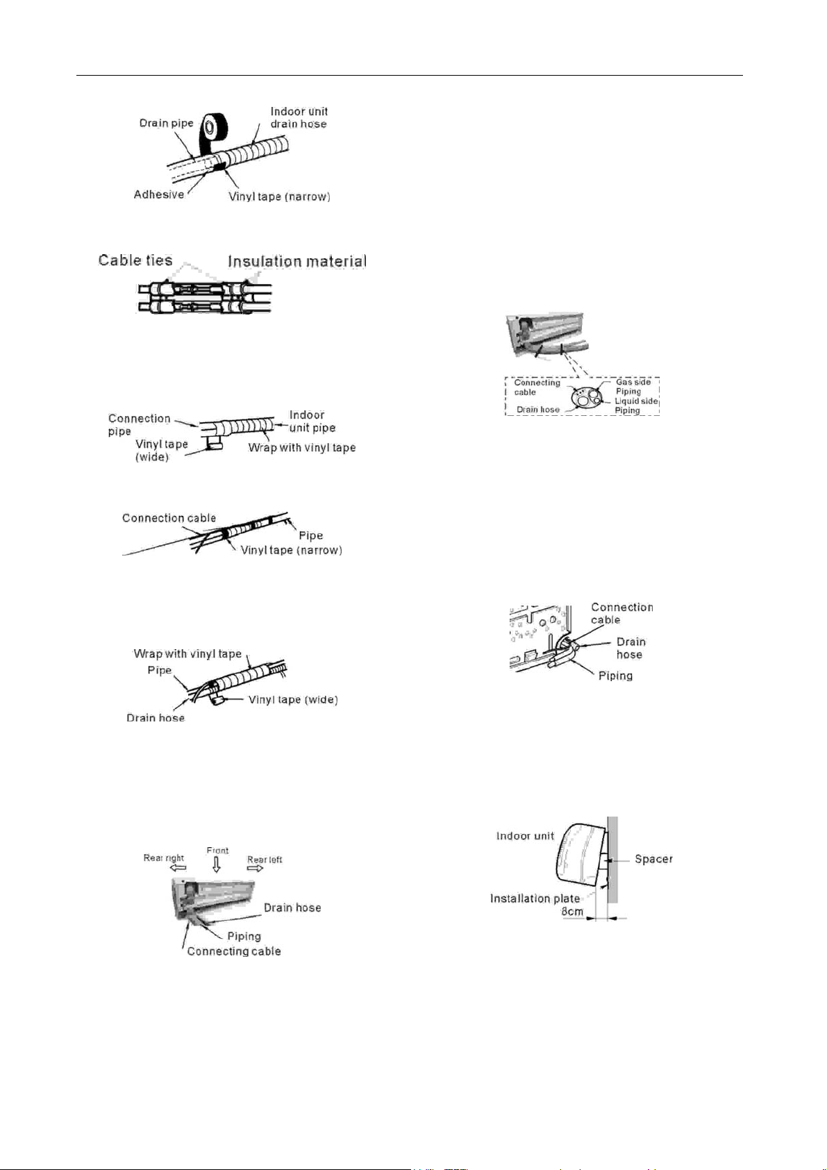
● When extending the drain hose of the indoor
unit, install the drain pipe extension as shown in
9
Tightening
Torque
(Kg.m)
Additional
Tightening
Torque (Kg.m)
GD Midea Refrigerant Equipment Co. Ltd Service manual for Electrolux split Series
adjacent diagram.
2.4.2.1.8 Wrap the insulation material around the
connecting portion.
● Overlap the connection pipe heat insulation
and the indoor unit pipe heat insulation material.
Bind them together with vinyl tape so that there is
no gap.
● Wrap the area which accommodates the rear
piping housing section with vinyl tape.
● Bundle the piping and drain hose together by
wrapping them with vinyl tape over the range
within which they fit into the rear piping housing
section.
indoor unit from the outdoor unit through the
piping hole.
● Do not connect the cable to the indoor unit.
● Make a small loop with the cable for easy
connection later.
2.4.2.2.3 Tape the drain hose and the connecting
cable. Be sure that the drain hose is located at the
lowest side of the bundle. Locating at the upper
side can cause drain pan to overflow inside the
unit.
Note: If the drain hose is routed inside the room,
insulate the hose with an insulation material so
that dripping from "sweating" (condensation) will
not damage furniture or floors.
*Foamed polyethylene or equivalent is
recommended.
2.4.2.2.4 Insert the piping, drain hose and the
connecting cable into the piping hole.
2.4.2.2 For rear left piping
Note: When viewed from the front of the indoor
unit.
2.4.2.2.1 Route the indoor tubing and the drain
hose to the required piping hole position in the
direction of left.
2.4.2.2.2 Insert the connecting cable into the
2.4.2.2.5 Indoor unit installation
● Hang the indoor unit from the hooks at the top
of the installation plate.
● Insert a spacer between the indoor unit and
the installation plate to separate the bottom of the
indoor unit from the wall.
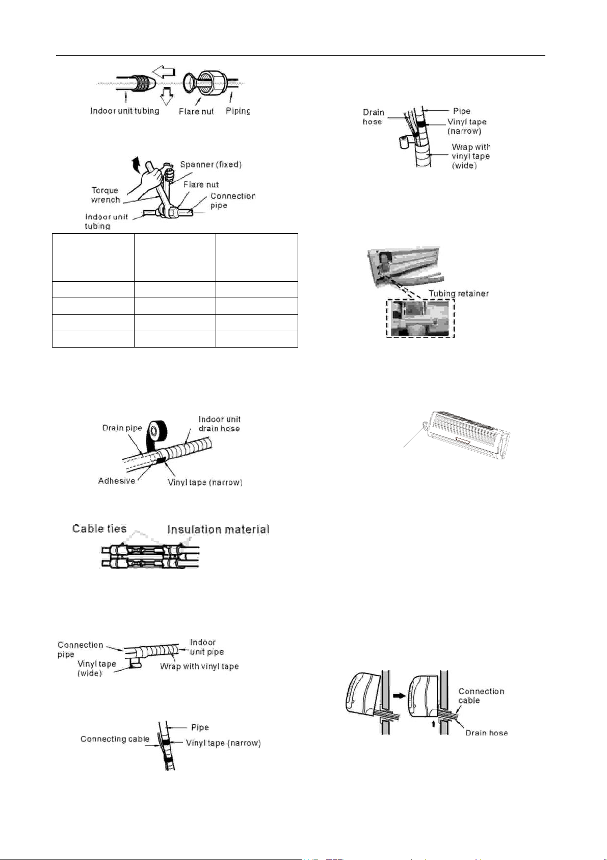
2.4.2.2.6 Connecting the piping to the indoor unit
and the drain hose to drain pipe.
● Align the centre of the piping and sufficiently
tighten the flare nut by hand.
10
GD Midea Refrigerant Equipment Co. Ltd Service manual for Electrolux split Series
wrapping them with vinyl tape over the range
within which they fit into the rear piping
housing section.
● Tighten the flare nut with a wrench, in
accordance with the following table.
2.4.2.2.8 Set the piping and the drain hose to the
back of the chassis with the tubing holder.
● Set the tubing retainer into position and
Outside
Diameter
1/4” (6.35mm) 1.6 2.0
3/8” (9.53mm) 3.0 3.5
1/2” (12.7mm) 5.0 5.5
5/8” (16.0mm) 7.5 8.5
Tightening
Torque
(Kg.m)
Additional
Tightening
Torque (Kg.m)
● When extending the drain hose of the indoor
unit, install the drain pipe extension as shown in
adjacent diagram.
tighten screw.
2.4.2.2.9 Reroute the piping and the drain hose
across the back of the chassis, for rear left side
external passage.
2.4.2.2.7 Wrap the insulation material around the
piping connections.
● Overlap the connection pipe heat insulation
and the indoor unit pipe heat insulation
material. Bind them together with vinyl tape
so that there is no gap.
● Wrap the area which accommodates the rear
piping housing section with vinyl tape.
Piping for passage
th r ough piping hole
2.4.2.2.10 Locating the indoor unit
● Remove the spacer.
● Hook the indoor unit onto the upper portion of
the installation plate.
(Engage the two hooks of the installation plate
into the openings at the rear top of the indoor unit.)
● Ensure that the hooks are properly seated on
the installation plate by moving the indoor unit left
and right.
● Press the lower left and right sides of the unit
against the installation plate until the hooks
engage into their slots (clicking sound).
● Bundle the piping and drain hose together by
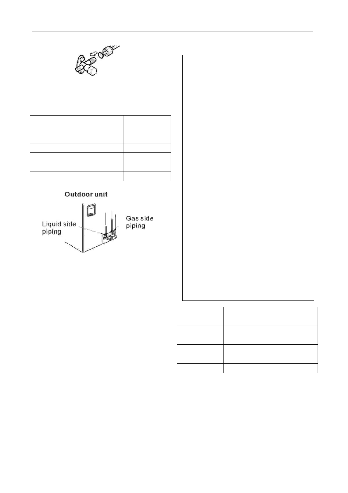
2.4.3 Connection of pipes - outdoor
2.4.3.1 Align the centre of the piping and
11
GD Midea Refrigerant Equipment Co. Ltd Service manual for Electrolux split Series
sufficiently tighten the flare nut by hand.
2.4.3.2 Finally, tighten the flare nut with torque
wrench until the wrench clicks.
● Tighten the flare nut with a wrench, in
accordance with the following table.
Outside
Diameter
1/4” (6.35mm) 1.6 2.0
3/8” (9.53mm) 3.0 3.5
1/2” (12.7mm) 5.0 5.5
5/8” (16.0mm) 7.5 8.5
Tightening
Torque
(Kg.m)
Additional
Tightening
Torque (Kg.m)
2.5 CONNECTING THE CABLE BETWEEN
INDOOR UNIT AND OUTDOOR UNIT
CAUTION
Ensure that all electrical work complies with
relevant Stan dards and Supply Authority
Service Rules.
An individual branch Circuit Breaker/Fuse must
be used with this Air Conditioner. See the
table following for electrical requirements.
Notes:
● Power Source and Power Cord
specifications must comply with requirements
following.
● Circuit Breaker or Fuse specified in this
manual must be installed in the power supply
circuit.
● For your safety and protection, this unit is
earthed through the power cord plug when
plugged into a matching wall receptacle.
● Do not connect two power cords together to
supply power to the air conditioner.
● Do not extend the power cable conductors
by cutting.
● Power supply should be in the range of
90%~110% of rated voltage.
● Refer to the attached Electrical Connection
Diagram located on the panel of the outdoor
unit to connect the wire.
Max. current
(A)
<=8 10 >=1.0
>8 & <=12.5 16 >=1.5
>12.5 & <=16 20 >=2.5
>16 & <=25 32 >=4.0
>25 & <=32 40 >=6.0
Max. current (A): Detail in SPECIFICATIONS list.
Note: To be used as a guide only.
2.5.1 Connect the cable to the indoor unit
● Connect the cable to the indoor unit by
connecting the wires to the terminals on the
control box individually according to the outdoor
unit connection. (Refer to Wiring diagram.)
(Ensure that the color of the wires of the outdoor
unit and the terminal number are the same as
12
Circuit Breaker /
Fuse Rating (A)
Wire Size
2
)
(mm
 Loading...