

AEG-Electrolux ES3CR27PSGMB, EU7705C, EXM21HC7, EXM18HC7, EXM27HC7 User Manual
...
GD Midea Refrigeration Equipment Co. Ltd
MULTI SPLIT TYPE, HEAT PUMP AIR CONDITIONERS
Technical service manual 2005
R407C multi Series
Indoor Models
[A SERIES] [B SERIES]
EL-KFR26G/TN2Y-A EL-KFR26G/TN2Y-B
EL-KFR36G/TN2Y-A EL-KFR36G/TN2Y-B
Outdoor Models
M2OA-18HRN2 M2OA-21HRN2
M3OA-27HRN2 M3OA-30HRN2
Multi SERIES
Page 1 of 33

1. Features
2. Specification
3. Dimensions
4. Refrigeration cycle diagram
5. Operation limits
6. Wiring diagram
7. Troubleshooting
8. Electronic function
9. Exploded view parts
10. Characteristic of temp. sensor
Page 2 of 33

1.Features
1.1 Compact design
1.2 High efficiency and quiet operation
1.3 Unitary outdoor unit design
Page 3 of 33
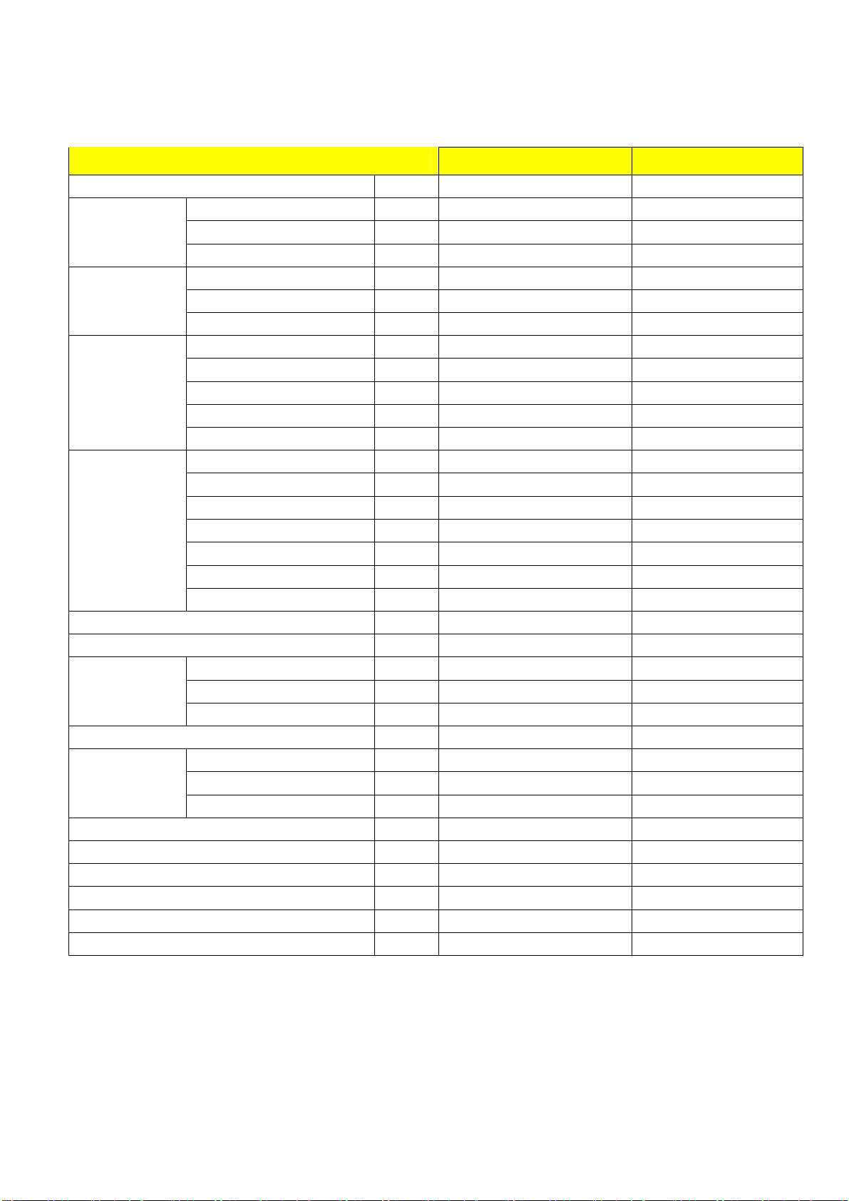
2 Specification
2.1 Indoor unit
Model EL-KFR26G/TN2Y-A(B) EL-KFR36G/TN2Y-A(B)
Power supply Ph-V-Hz 1, 220-240V~,50Hz 1, 220-240V~,50Hz
Capacity Btu/h 9000 12000
Cooling
Heating
Indoor fan motor
Indoor coil
Indoor air flow (Hi/Mi/Lo) m3/h 500/460/410 680/520/420
Indoor noise level (Hi/Mi/Lo) dB(A) 40.5/37.4/34.6 42.0/35.0/30.0
Indoor unit
Design pressure(Hi/Lo) MPa 2.8/1.2 2.8/1.2
Refrigerant piping
Connection wiring No No
Plug type 10A 16A
Thermostat type Electronic control Electronic control
Operation temp
Ambient temp
Application area m2 14-21 18-26
Input W 36.5 51.5
Rated current A 0.17 0.24
Capacity Btu/h 10000 13000
Input W 36.5 51.5
Rated current A 0.17 0.24
Model RPG13H RPG20D
Brand Welling WELLING
Input W 36.5 51.5
Capacitor uF 1.2 1.5
Speed(hi/mi/lo) r/min 1180/1080/1000 1250/1000/800
a.Number of rows 2 2
b.Tube pitch(a)x row pitch(b) mm 21x13.37 21×13.37
c.Fin spacing mm 1.3 1.3
d.Fin type (code) Hydrophilic aluminium Hydr0philiC aluminium
e.Tube outside dia.and type mm
f.Coil length x height x width mm 578X252X26.74 635×315×27.34
g.Number of circuits 2 2
Dimension (W*H*D) mm 750×250×214(210) 815x282x217
Packing (W*H*D) mm 837X340X295 915x360x295
Net/Gross weight Kg 9/11 10.5kg/12kg
Liquid side/ Gas side mm
Max. refrigerant pipe length m 10 10
Max. difference in level m 5 5
φ7 INNEGROOVE TUBE φ7, innergroove tube
Ф6.35/Ф9.53 Ф6.35/Ф12.7
℃
℃
17-30 17-30
18-45 18-45
Page 4 of 33
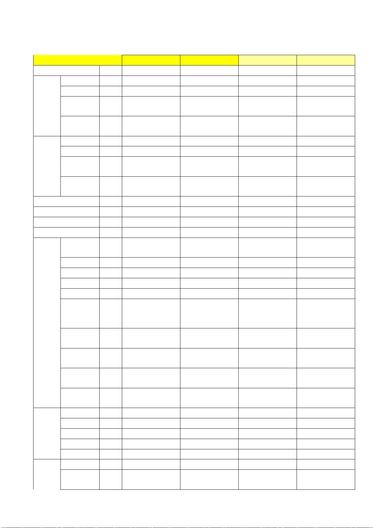
2.2 Outdoor unit
Model M2OA-18HRN2 M2OA-21HRN2 M3OA-27HRN2 M3OA-30HRN2
Power supply
Capacity Btu/h 9000X2 9000+12000 9000x3 9000x2+12000
Input W 1050X2 960+1100 1050X3 1800+1300
Cooling
Rated
current
EER
Capacity Btu/h 10600X2 10000+13000 10600x3 13000+20000
Input W 1080X2 960+1140 1080X3 1750+1300
Heating
Rated
current
COP
Moisture Removal L/h 1.0x2 1.0+1.2 1.0x3 1.0x2 +1.2
Max. input consumption W 1330X2 1500+1900 1330X3 2200+1800
Max. current A 6.0X2 7.0+8.0 10.0 +8.2 10.0 +8.2
Starting current A 19.8 19.8+30 40+30 40+30
Model PG180X1C-4DZ3X2
Type ROTARY Rotary Rotary Rotary
Brand GD TOSHIBA GD TOSHIBA GD Toshiba GD Toshiba
Capacity Btu/h 10800X2 10800+13650 18080; 13650 18080; 13650
Input W 1000X2 1000+1310 1760; 1310 1760; 1310
Rated
Compre
ssor
current(RLA
)
Locked rotor
Amp(LRA)
Thermal
protector
Capacitor uF 25X2 25+35
Refrigerant
oil
Model
Outdoor
fan
motor
Brand WeiLing WeiLing Welling Welling
Input W 154 154 107Wx2 107Wx2
Capacitor uF
Speed r/min
Outdoor
coil
a.Number of rows
b.Tube pitch(a)x
row pitch(b)
Ph-V-Hz
1Ph,220-240V,50Hz 1Ph,220-240V,50Hz 1Ph,220-240V,50Hz 1Ph,220-240V,50Hz
A 4.6X2 5+6 4.6X3 8.2+5.8
Btu/w
.h
8.6 8.8 8.5, 8.9, 8.5,
A 4.8X2 5+6 4.8X3 8.2+5.8
Btu/w
.h
9.8 9.6
PG180X1C-4DZ3+P
G225X2C-4FT
PG295X2CS-4KU1;
PG225X2C-4FT
9.6 10.2/ 9.6
PG295X2CS-4KU1;
PG225X2C-4FT
A 4.4X2 4.4+6.1 8.5; 6.1 8.5; 6.1
A 24X2 24+31 44, 31 44, 31
UP3QE0591-T61X2
UP3QE0591-T61+U
P3RE0591-T56
Internal Internal
35uF/440VAC;
35uF/440VAC
35uF/440VAC;
35uF/440VAC
ml 400X2 400+ 480 750; 480 750; 480
YDK50-4G1 YDK50-4G1
4uFx2 4uFx2
1150 1150
2 2
25.4x22 25.4x22
mm
YDK69-6 YDK69-6
4 4
900/670 900/670
2 2
25.4X22 25.4X22
Page 5 of 33
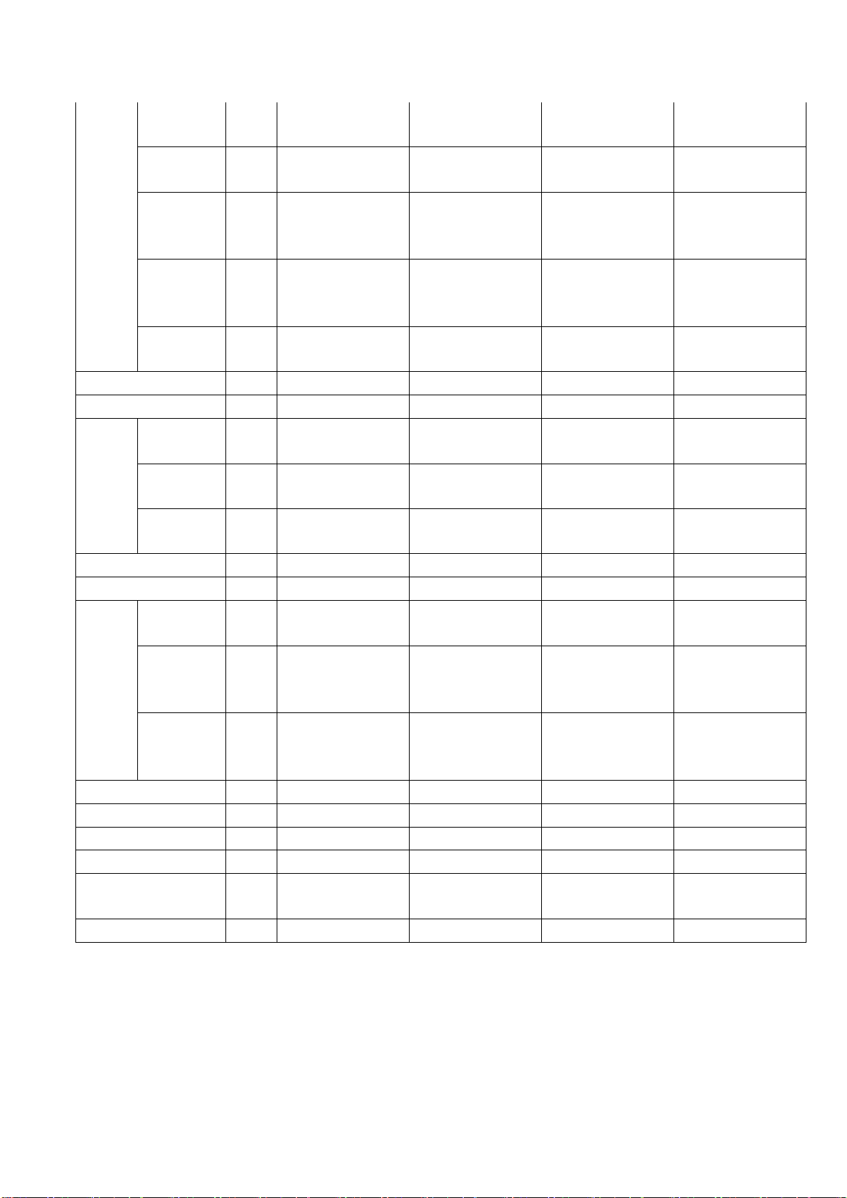
c.Fin
spacing
d.Fin type
(code)
e.Tube
outside
dia.and type
f.Coil length
x height x
width
g.Number of
circuits
Outdoor air flow m3/h
Outdoor noise level dB(A)
Dimension(
W*H*D)
Outdoor
unit
Refrigerant type g R407C/800X2 R407C/750+1000 R407C/ 1470+820 R407C/ 1470+820
Design pressure(Hi/Lo) MPa 2.8/1.2 2.8/1.2 2.6 2.6
Refriger
ant
piping
Connection wiring No No No No
Plug type No NO No No
Thermostat type Electronic control Electronic control Electronic control Electronic control
Operation temp
Ambient temp
Application area m2 (14-21)x2 14-21; 18-26 (14-21)x3 (14-21)x2,16-24
Packing
(W*H*D)
Net/Gross
weight
Liquid side/
Gas side
Max.
refrigerant
pipe length
Max.
difference in
level
mm
mm
mm
mm
mm
Kg
mm(in
ch)
m 10 10 10 (each unit) 10 (each unit)
m 5 5 5 (each unit) 5 (each unit)
℃
℃
1.7 1.7
HYDROPHILIC
ALUMINIUM
Ф9.53
INNERGROOVE
TUBE
810X610X44 810X610X44
12 12
1900 2070
58 58 60 62
895X345X655 895X345X655
1050X470X720 1050X470X720
73/77 60/65 90/94 90/94
Ф6.35/Ф9.53
17-30 17-30 17~30 17~30
18~45(cooling);
-7~30(heating)
HYDROPHILIC
ALUMINIUM
Ф9.53
INNERGROOVE
TUBE
Ф6.35/Ф9.53; Ф
6.35/Ф12.7
18~45(cooling);
-7~30(heating)
Ф9.53, Innergroove
1.5 1.5
Hydrophilic
aluminium
tube
813X812X44 813X812X44
5(A System);4(B
System)
1450x2 1450x2
860X830X330 860X830X330
983X915X425 983X915X425
Ф6.35/Ф9.53;Ф
6.35/Ф12.7
18~45(cooling);
-7~30(heating)
Hydrophilic
aluminium
Ф9.53, Innergroove
tube
5(A System);4(B
System)
Ф6.35/Ф9.53
18~45(cooling);
-7~30(heating)
Page 6 of 33
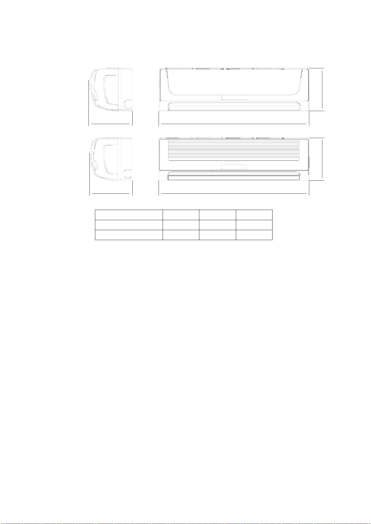
3.Dimensions
3.1 Indoor unit
Pan el A
Pan el B
C
D B
C
A B
A B C
EL-KFR26G/TN2Y-A(B)
EL-KFR36G/TN2Y-A(B)
214 750 250
217 815 282
Page 7 of 33
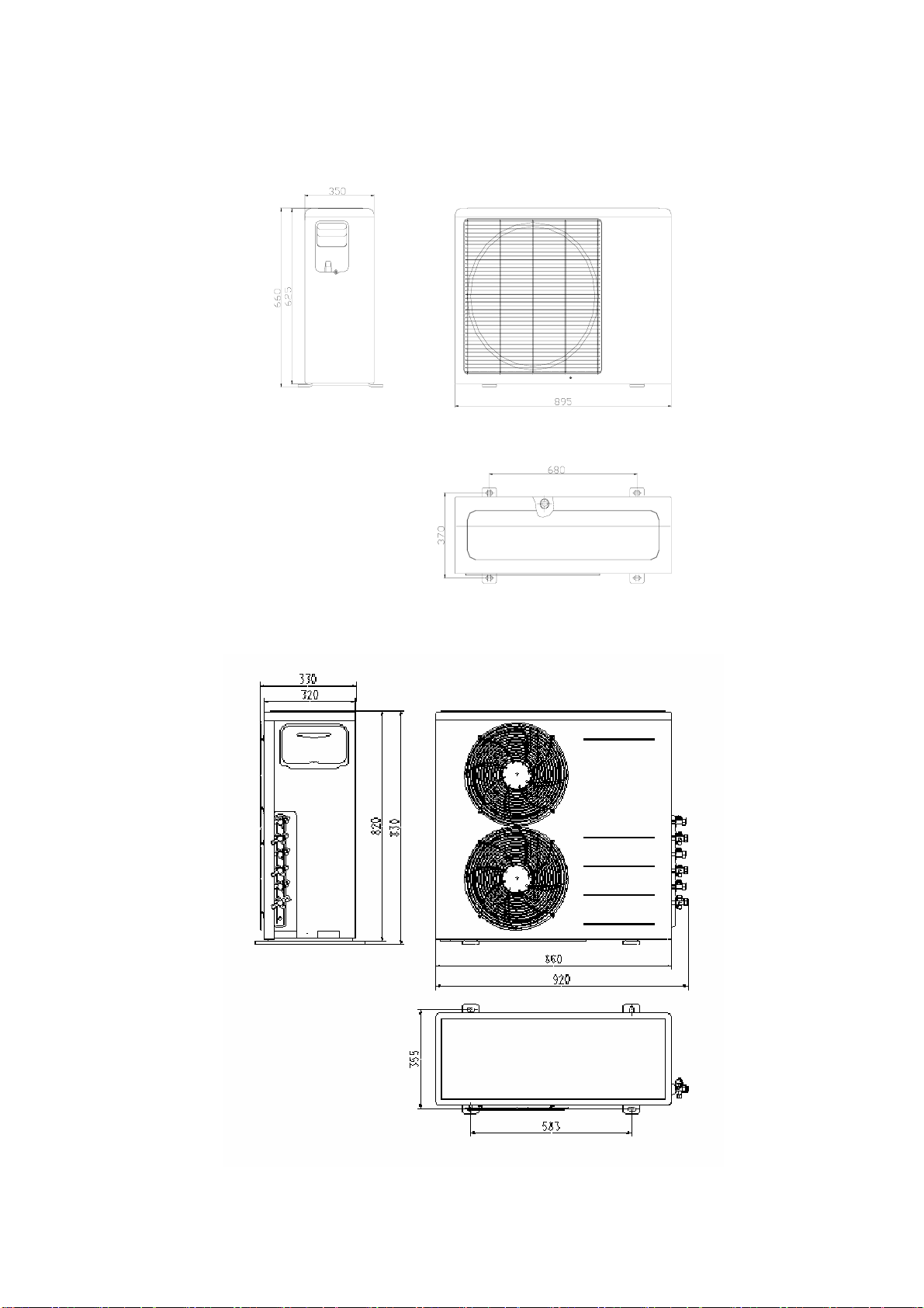
3.2 Outdoor unit
Outdoor unit 18K/21K
Outdoor unit 27K/30K
Page 8 of 33
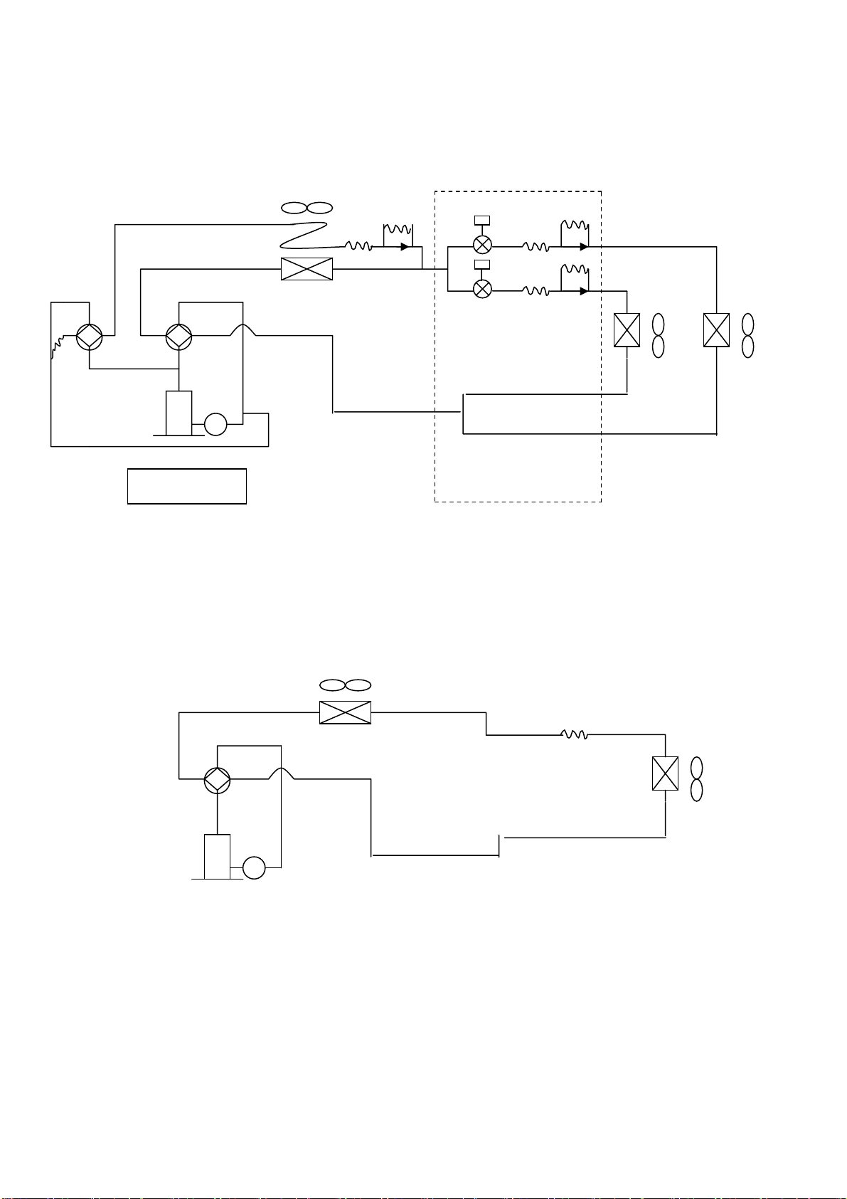
4.Refrigeration cycle diagram
“1 drive 3 system” is made up of one “1 drive 1 system” and one “1 drive 2 system”.
SV2
SV1
PMV1
PMV2
2#
1# T2
T1
Compressor
refrigeration distributor
1 drive 2 system
SV1:Primary four-way valve SV2:Secondary four-way valve PMV1,PMV2:Electronic expansive valve
T1,T2:Indoor pipe temperature sensor
Condenser
Four-way valve
Evaporator
Compressor
1 drive 1 system
Notice:For 1 drives 2 system, there are two individual refrigerant circuit and two compressors, but for the 1drive 2
system in the 1 drive three system, there is only one refrigerant circuit and only one compressor.
Page 9 of 33
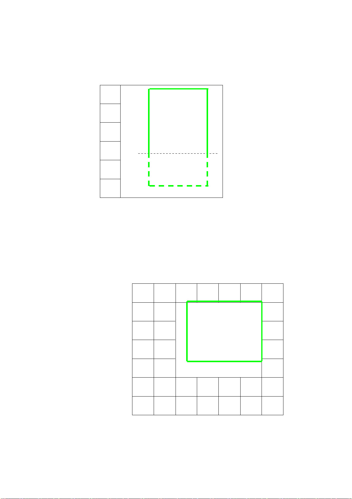
5.Operation limits
5.1Cooling operation
Outdoor unit air temp.℃ DB
45
17
-7
Indoor air temp.
Note: 1.The chart is the result from the continuous operation under constant air temperature
Condition. However, excludes the initial pull-down stage.
2.The operation range below the dashed is the result added the low ambient kit.
5.2Heating operation
COOLING
0 17 32
℃ DB
Indoor air temp. ℃ DB
30
25
20
15
10
5
Note : The chart is the result from the continuous operation under constant air
temperature conditions. However, excludes the initial pull-down stage.
-5 5 15 25
Outdoor unit air temp.
℃ DB
Page 10 of 33
 Loading...