


Section 61221002L2-5B
Issue 2, August 2003
CLEI Code: SLL5R3DG_ _
ADTRAN® AHDSL2 Asynchronous H2TU-C Line Card for
Alcatel Litespan® Channel Bank Assemblies Using Narrowband Pairs
Installation and Maintenance Practice
CONTENTS |
|
||
1. |
General ......................................................................... |
1 |
|
2. |
Applications ................................................................. |
3 |
|
3. |
Installation .................................................................... |
3 |
|
4. |
Deployment Guidelines ............................................... |
8 |
|
5. |
Maintenance ................................................................. |
9 |
|
6. |
Troubleshooting Procedures ...................................... |
10 |
|
7. |
Product Specifications ............................................... |
10 |
|
8. |
Warranty and Customer Service ................................ |
10 |
|
Appendix A. HDSL2 Loopbacks .................................. |
A-1 |
||
Appendix B. TL1 H2TU-C Tutorial .............................. |
B-1 |
||
Appendix C. Metallic Test Access Unit (MTAU) |
|
||
|
|
Testing Capabilities .................................. |
C-1 |
FIGURES |
|
||
Figure 1. ADTRAN H2TU-C for Litespan .................... |
1 |
||
Figure 2. H2TU-C Span Powering Diagram .................. |
3 |
||
Figure 3. |
Deployment from a Litespan |
|
|
|
|
Channel Bank .................................................. |
3 |
Figure 4. |
Deployment Guidelines .................................. |
8 |
|
Figure C-1. SPLIT Mode ................................................ |
C-1 |
||
Figure C-2. MON Mode ................................................. |
C-2 |
||
TABLES |
|
|
|
Table 1. |
LED Indicators ................................................ |
2 |
|
Table 2. |
Compliance Codes .......................................... |
4 |
|
Table 3. |
Administration Commands ............................. |
5 |
|
Table 4. |
Cross-Connect Commands.............................. |
5 |
|
Table 5. |
Maintenance Commands ................................. |
5 |
|
Table 6. HDSL Provisioning Commands ..................... |
6 |
||
Table 7. |
T1 Provisioning Commands ........................... |
6 |
|
Table 8. |
Testing Commands ......................................... |
7 |
|
Table 9. |
Worksheet PW-1 Factors ................................ |
8 |
|
Table 10. |
Power Parameters ............................................ |
8 |
|
Table 11. HDSL2 Loss Values........................................ |
9 |
||
Table 12. Loop Insertion Loss Data ................................ |
9 |
||
Table 13. |
Troubleshooting Guide ................................. |
10 |
|
Table 14. ADTRAN H2TU-C Specifications ............... |
11 |
||
Table A-1. In-Band Addressable Loopback |
|
||
|
|
Codes .................................................. |
A-2, A-3 |
1. GENERAL
The ADTRAN asynchronous Litespan HDSL2 Transceiver Unit for the Central Office (H2TU-C) P/N 1221002L2, is a DS1 interface unit that provides full T1 service over 2-wire interface facilities. The Litespan H2TU-C combines ADTRAN HDSL2 technology and Litespan technology to provide an HDSL2 interface to a Litespan system. ADTRAN’s
H TUC
1221002L2 NB
DSL
STAT
RLOS
HLOS
HCRC
ARM
LBK
B8ZS
AHDSL2
Figure 1. ADTRAN H2TU-C for Litespan
Litespan H2TU-C is certified by Alcatel® to safely operate in Litespan 2000, 2012 and Starspan systems. The unit is licensed under the Asynchronous High-bit-rate Digital Subscriber Line 2-wire T1 Interface Unit H2TU-C channel unit type. Figure 1 is an illustration of the ADTRAN H2TU-C.
Revision History
This is the second release of this document. Additional footnotes have been added to Tables 6, 7, and A-1.
Features
•Lightning and power cross-protection, static discharge immunity, and local power bus fusing for line card safety and protection
•1.552 kbps HDSL2 transmission over a single pair
•Front panel status LEDs
•Performance monitoring and alarm reporting
•Low power consumption
•Span powering for the H2TU-R
•Corrosion-preventive sealing current over a single twisted copper pair
•Troubleshooting functionality
61221002L2-5B |
Trademarks: Any brand names and product names included in this document are |
1 |
|
trademarks, registered trademarks, or trade names of their respective holders. |
|

Table 1 lists and defines the H2TU-C Front Panel LED indicators.
Each ADTRAN Litespan H2TU-C line card provides a 1.552 kbps data transport over one unconditioned CSA copper pair. These CSA loops can range up to 12 kft of 24-AWG twisted pair wire.
The Litespan H2TU-C can be used in Litespan 2000, Litespan 2012, and Litespan ONU channel bank assembly (CBA) systems containing Litespan system software versions of 11.0.0 or higher. Each H2TU-C works with the following multiple list versions of the HDSL2 unit remote end (H2TU-R):
Part Number |
Description |
|
|
|
|
1222024L6 |
T200 H2TU-R, Local Power |
|
1223024L9 |
T200 H2TU-R, Local Power |
|
1221026L6 |
T200 H2TU-R MON |
|
1222026L6 |
T200 H2TU-R MON |
|
1222026L9 |
T200 H2TU-R Q |
|
1223026L9 |
T200 H2TU-R Q |
|
122x024L7 |
T200 H2TU-R, Local Power |
|
122x026L1 |
T200 H2TU-R |
|
122x026L5 |
T200 H2TU-R B |
|
122x026L7 |
T200 H2TU-R S |
|
(where x = 1, 2 or 3) |
|
|
The H2TU-C can be deployed in circuits consisting of one H2TU-C and one H2TU-R. Lightning and power cross-protection is provided at each twisted pair interface of the ADTRAN H2TU-C line card. Local power bus fusing is also used to protect the Litespan channel bank backplane, Litespan bank power supplies, and neighboring Litespan line cards in the event of catastrophic line card failure.
The Litespan H2TU-C uses a DC-to-DC converter to derive span powering voltage from the Litespan
–48 VDC switched battery supply.
Simplex current of 30 mA of current may be coupled onto the HDSL2 loop span to power the H2TU-R (see
Figure 2).
NOTE
Depending on the type of H2TU-R used in the circuit, different provisioning options will be available.
|
|
Table 1. LED Indicators |
|
|
|
|
|
LED |
Indication |
Description |
|
|
|
|
|
|
Off |
Indicates loss of power to H2TU-C |
|
STAT |
Green |
Normal operation; H2TU-C is in sync with the H2TU-R |
|
Flashing Green |
Acquiring HDSL2 synchronization with H2TU-R |
||
|
|||
|
Red |
Failure indication; unable to start/load firmware |
|
|
|
|
|
|
Off |
HDSL2 signal achieved |
|
HLOS |
Red |
HDSL2 loss of synchronization |
|
|
Flashing Red |
DC continuity fault detected on HDSL2 loop |
|
|
|
|
|
RLOS |
Off |
DS1 signal from the CPE is present at H2TU-R |
|
Red |
DS1 signal from the CPE is absent at H2TU-R or Framing does not match |
||
|
|||
|
|
|
|
|
Green |
HDSL2 SNR margin is optimum (6 dB or greater) |
|
DSL |
Yellow |
HDSL2 SNR margin is marginal (1 dB to 5 dB) |
|
Red |
HDSL2 SNR margin is poor (0 dB) |
||
|
|||
|
Flashing |
HDSL2 pulse attenuation is > 30 dB |
|
|
|
|
|
|
Off |
No HDSL2 CRC errors within the last 30 minutes |
|
HCRC |
Yellow |
Four or more HDSL2 CRC errors in last 30 minutes |
|
|
Red |
HDSL2 CRC errors are being detected |
|
|
|
|
|
|
Off |
The unit is not armed or in loopback |
|
ARM/LBK |
Green |
The unit is in loopback |
|
|
Yellow |
The unit is armed but not in loopback |
|
|
|
|
|
B8ZS |
Green |
The line code is B8ZS |
|
Off |
The line code is AMI |
||
|
|||
|
|
|
2 |
61221002L2-5B |
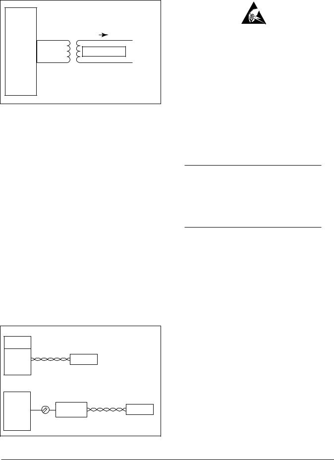
SPAN CURRENT
TIP (+)
HDSL2 |
SPAN POWER |
−190V |
RING (−)
Figure 2. H2TU-C Span Powering Diagram
2. APPLICATIONS
The ADTRAN HDSL2 system provides a cost-effective alternative for deploying T1 service over metallic cable pairs. In contrast with traditional T1 service equipment, ADTRAN HDSL2 can be successfully deployed over one unconditioned, nonloaded, bridged-tapped copper pair CSA loop (see
Deployment Guidelines, Section 4).
Litespan HDSL2 deployment is typically made from a Litespan 2000, Litespan 2012, or Litespan ONU channel bank assembly. Figure 3 shows possible ADTRAN HDSL2 deployments from a Litespan channel bank assembly. ADTRAN HDSL2 systems can be deployed quickly without the use of expensive T1 repeater equipment on standard CSA loops while using the existing massive copper-fed twisted line pairs in use by the industry.
ADTRAN uses negative ground-referenced span powering voltage (–190 VDC) on HDSL2 loop. H2TU-R span powering can be disabled to allow locally powered H2TU-R applications, if desired.
Litespan 2000 or 2012 System with Litespan H2TU-C deployment |
|
|||
Common |
|
|
|
|
Control |
|
|
|
|
Channel Bank |
HDSL2 Loop Pair |
HDSL2 Unit |
|
|
Assembly with |
|
|
|
|
|
|
Remote End |
|
|
a Litespan |
|
|
|
|
|
|
|
|
|
H2TU-C |
|
|
|
|
Installed |
|
|
|
|
Typical Starspan System |
|
|
|
|
HDT |
|
|
|
|
Common |
|
|
|
|
Control |
OLNK |
|
HDSL2 Loop Pair |
|
|
|
|
||
|
|
ONU-96 with |
HDSL2 Unit |
|
|
|
an installed |
||
|
|
Remote End |
||
High-Density |
|
Litespan H2TU-C |
||
|
|
|||
Fiber Bank |
|
|
|
|
Figure 3. Deployment from a Litespan Channel Bank
3. INSTALLATION
C A U T I O N !
SUBJECT TO ELECTROSTATIC DAMAGE
OR DECREASE IN RELIABILITY.
HANDLING PRECAUTIONS REQUIRED.
After unpacking the unit, inspect it for damage. If damage is noted, file a claim with the carrier, then contact ADTRAN. Refer to Warranty and Customer Service.
The Litespan H2TU-C plugs directly into a Litespan channel bank assembly channel unit slot. Litespan system software must be version 11.0.0 or higher. The tip and ring connections from the H2TU-C to the shelf are made through the following card edge pins:
•Narrowband Tip – Pin A3
•Narrowband Ring – Pin A4
CAUTION
Do not deploy the Litespan H2TU-C into any Litespan channel bank assembly slot that has ADSL Power Distribution Fuse and Alarm (PDFA) connections to the wideband pairs of the channel bank assembly.
This unit supports narrowband cabling only on the Litespan RT shelf. For more information regarding cabling, reference Alcatel document Mechanical Unit Descriptions, OSP 363-405-270.
Upon insertion of an H2TU-C into an unprovisioned slot, the STAT LED should turn red immediately. The STAT LED will remain red until the Litespan bank recognizes the insertion of the card and downloads the AHDSL2 channel unit type code into the line card. Typically, the STAT LED will remain red for approximately 15 to 20 seconds (time may vary). Approximately 3 to 4 seconds after the STAT LED turns off, the HLOS LED will turn red and remain so until the H2TU-C and H2TU-R units synchronize with each other over the HDSL2 loop. The STAT LED will turn green after synchronization of the HDSL2 loop.
61221002L2-5B |
3 |

CAUTION
Prior to installing or removing the Litespan H2TU-C, observe the following warning: If the Litespan H2TU-C is removed from a line card slot, wait at least 15 seconds before reinsertion. If connected to the MTI craft interface terminal, wait until the message “AID:MJ,UEQ.” appears (where “AID” is the access identifier). This informs the Litespan common control assembly that the H2TU-C has been removed from its slot, after which the common control assembly begins looking for the reinsertion of the line card. Reinsertion any earlier than this may temporarily lock the H2TU-C into a nonfunctional state because the common control assembly will not send the AHDSL2 equipment type code to the H2TU-C line card.
Compliance
This product is intended for installation in restricted access locations only and in equipment with a Type “B” or “E” enclosure.
WARNING
Up to –200 VDC may be present on telecommunications wiring. The DSX-1 interface is intended for connection to intra-buildingwiringonly.Ensurechassisground is properly connected.
This product provides span powering voltage (negative only with respect to ground, –190 VDC nominal, GFI protection < 5 mA) and meets all requirements of Bellcore GR-1089-CORE (Class A2) and ANSI T1.418-2002. This product is NRTL listed to the applicable UL standards.
Table 2 shows the compliance codes for this product.
Table 2. Compliance Codes
Code |
Input |
Output |
|
|
|
Power Code (PC) |
F |
C |
Telecommunication Code (TC) |
– |
X |
Installation Code (IC) |
A |
– |
|
|
|
Provisioning
Provisioning of the H2TU-C is through the craft interface on the Maintenance and Test Interface (MTI) card either via TL1 commands or the Litecraft Pro Graphical User Interface (GUI). Refer to the Litecraft Pro Access Configuration Guide
(P/N 61221002L1-31) for detailed GUI information.
The provisioning and performance monitoring VT100 terminal screens may be viewed from the H2TU-R DB-9 RS-232 craft interface port. However, the provisioning options may not be changed or manipulated in any way from the H2TU-R.
NOTE
Please reference Alcatel document TL1 Software Reference, OSP 363-405-502 for detailed information regarding provisioning through the MTI craft interface.
The H2TU-C TL1/Litecraft commands are grouped as follows:
•Administration
•Cross-Connect Provisioning
•Maintenance
•HDSL Provisioning
•T1 Provisioning
•Testing
Administration Commands
Administration commands are used to remove or restore the H2TU-C to service, place equipment and facilities In-Service (IS) and Out-of-Service (OOS), and display system inventory. These commands are listed and defined in Table 3.
Cross-Connect Provisioning Commands
Cross-connect Provisioning commands are used to manage cross-connections. These commands are listed and defined in Table 4.
Maintenance Commands
Maintenance commands are use to clear and retrieve Performance Monitoring (PM) information and to display alarm Statistics. Table 5 lists and defines the available
TL1/Litecraft Maintenance commands.
4 |
61221002L2-5B |

Provisioning Commands
Upon initial insertion of the Litespan H2TU-C into the Litespan system, configuration options are downloaded automatically to the line card and take precedence over the ADTRAN default provisioning options.
NOTE
The provisioning options stored in the shelf controller can be pre-configured by the user through the Litecraft Pro interface.
Table 6 and Table 7 list and define the available HDSL provisioning commands. The H2TU-C should be pre-provisioned as indicated under “Pre-Configurable Value.”
|
Table 3. Administration Commands |
|
|
|
|
TL1 Commands |
|
Description |
|
|
|
RMV-HDSL |
|
Removes the Litespan H2TU-C from service (OOS) |
|
|
|
RST-HDSL |
|
Restores the Litespan H2TU-C to service (IS) |
|
|
|
ENT-EQPT |
|
Enters or assigns a unit to a slot position |
|
|
|
DLT-EQPT |
|
Deletes or unassigns a unit to a slot position |
|
|
|
ED-HDSL or ED-T1 |
|
Edits the equipment |
|
|
|
|
Table 4. Cross-Connect Commands |
|
|
|
|
TL1 Commands |
|
Description |
|
|
|
ENT-CRS-T1 |
|
Enters a cross-connection |
|
|
|
DLT-CRS-T1 |
|
Deletes a cross-connection |
|
|
|
RTRV-CRS-T1 |
|
Retrieves existing cross-connections |
|
|
|
|
Table 5. Maintenance Commands |
|
|
|
|
TL1 Commands |
|
Description |
|
|
|
INIT-REG-HDSL or INIT-REG-T1 |
|
Clears performance monitoring data and sets all values to zero (0) |
|
|
|
RTRV-PM-HDSL or RTRV-PM-T1 |
|
Retrieves performance monitoring data |
|
|
|
RTRV-ALM-HDSL |
|
Retrieves alarms |
|
|
|
61221002L2-5B |
5 |

Table 6. HDSL Provisioning Commands
TL1 |
Litecraft |
H2TU-C |
H2TU-C |
Corresponding |
Pre-Configurable |
Commands |
Parameters |
Options |
Available Settings |
Litecraft Settings |
Value |
|
|
|
|
|
|
ED-HDSL |
NIDLPBK |
NIU Loopback |
Disabled |
NO |
YES |
|
|
|
Enabled |
YES |
|
|
|
|
|
|
|
ED-HDSL |
LPBKTMO |
Loopback Time |
0 |
0 |
120 |
|
|
Out1 |
20 Minutes |
20 |
|
|
|
|
60 Minutes |
60 |
|
|
|
|
120 Minutes |
120 |
|
|
|
|
|
|
|
ED-HDSL |
LPBKACTR |
New England |
Disabled |
0000000000000000 |
0000000000000000 |
|
|
Loopback2 |
Enabled |
0000000000000001 |
|
|
|
|
|
|
|
ED-HDSL |
FT1MODE |
Latching |
T1 |
NO |
NO |
|
|
Loopback |
FT1 |
YES |
|
|
|
|
|
|
|
ED-HDSL |
LP |
Span Power |
Disabled |
SINK |
SOURCE |
|
|
|
Enabled |
SOURCE |
|
|
|
|
|
|
|
ED-HDSL |
LPBKDEACTCDE |
Customer Loss |
AIS |
0000000000000000 |
0000000000000001 |
|
|
Indicator3 |
AIS/CI |
0000000000000001 |
|
|
|
|
Loopback |
0000000000000010 |
|
|
|
|
|
|
|
ED-HDSL |
LPBKACTC |
PRM setting1,3 |
None |
0000000000000000 |
0000000000000001 |
|
|
|
SPRM |
0000000000000001 |
|
|
|
|
NPRM |
0000000000000010 |
|
|
|
|
Auto (Both) |
0000000000000011 |
|
|
|
|
|
|
|
ED-HDSL |
NTWKKPALV |
Network Keep |
Disabled |
NO |
NO |
|
|
Alive |
Enabled |
YES |
|
|
|
|
|
|
|
ED-GOS-HDSL |
SNR |
SNR Margin |
0 to 15 dB |
0 to 15 |
|
|
|
Alarm |
|
|
|
|
|
Threshold |
|
|
|
|
|
|
|
|
|
ED-GOS-HDSL |
LA |
Loop |
0 to 40 dB |
0 to 40 |
|
|
|
Attenuation |
|
|
|
|
|
Alarm |
|
|
|
|
|
Threshold |
|
|
|
|
|
|
|
|
|
1Some settings may not be available at the H2TU-R.
2This option is available only if the H2TU-R P/N 1221026L1, 1222026L1 or 1223026L1 is used in the circuit. 3This option is not available if the H2TU-R P/N 1221026L6, 1222026L6 or 1223026L1 is used in the circuit.
Table 7. T1 Provisioning Commands
TL1 |
Litecraft |
H2TU-C |
H2TU-C |
Corresponding |
Pre-Configurable |
Commands |
Parameters |
Options |
Available Settings |
Litecraft Settings |
Value |
|
|
|
|
|
|
ED-T1 |
LINECDE |
Line Code |
AMI |
AMI |
B8ZS |
|
|
|
B8ZS |
B8ZS |
|
|
|
|
|
|
|
ED-T1 |
FMT |
Framing1 |
SF |
SF |
AUTO |
|
|
|
ESF |
ESF |
|
|
|
|
Unframed |
UNFR |
|
|
|
|
AUTO |
AUTO |
|
|
|
|
|
|
|
ED-T1 |
AT |
DS1 TX Level1 |
0 dB |
0.0 |
0.0 |
|
|
|
−7.5 dB |
7.5 |
|
|
|
|
−15 dB |
15.0 |
|
|
|
|
|
|
|
1Some settings may not be available at the H2TU-R.
6 |
61221002L2-5B |

Testing Commands
The H2TU-C testing commands are used to initiate and terminate loopbacks and disconnect for testing purposes. Table 8 lists and defines the TL1/Litecraft testing commands.
NOTE
Before entering loopbacks, the user needs to remove the card from service. This can be done with the RMV-HDSL command. The card can then be restored to service with the RST-HDSL command.
NOTE
When entering access identification (AID), the user needs to specify whether a loopback command is for a C or an R. For example, AID=RT-1-21-C.
Alarms
The selectable alarm threshold crossing alerts are as follows:
•SNR margin threshold
•HDSL2 and DS1 15-minute ES, SES, UAS thresholds
•HDSL2 and DS1 daily ES, SES, UAS thresholds
•HDSL2 loop attenuation threshold
•DS1 15-minute CV-L, B8ZSS-L, and PDVS-L thresholds
•DS1 daily CV-L, B8ZSS-L, and PDVS-L thresholds
The following additional alarm conditions are provided by the H2TU-C:
•HDSL2 LOSW alarm
•HDSL2 unit failure alarm
•HDSL2 loop continuity alarms
•HDSL2 circuit reset
•DS1 LOS alarm
•H2TU-R AIS, RAI, INCRAI-CI
Power Requirements
When deploying any Litespan H2TU-C, the power requirements for the application should also be considered for product mix calculations and maximum number of Litespan H2TU-Cs within a channel bank assembly. Use Worksheet PW-1 in the “Engineering and Planning” section of Alcatel practice, OSP TL1 Software Documentation, release 7.1 or higher, to determine whether a particular combination of channel units is within power-drain specifications.
Table 8. Testing Commands
TL1 |
Litecraft |
H2TU-C |
H2TU-C Available |
Corresponding |
Commands |
Parameters |
Options |
Settings |
Litecraft Settings |
|
|
|
|
|
OPR-LPBK-HDSL |
LOCN (AID-C) |
H2TU-C Network Loopback |
Loop Up |
NEND |
|
|
|
|
|
RLS-LPBK-HDSL |
LOCN (AID-C) |
H2TU-C Network Loopback |
Loop Down |
NEND |
|
|
|
|
|
OPR-LPBK-HDSL |
LOCN (AID-C) |
H2TU-C Customer Loopback |
Loop Up |
FEND |
|
|
|
|
|
RLS-LPBK-HDSL |
LOCN (AID-C) |
H2TU-C Customer Loopback |
Loop Down |
FEND |
|
|
|
|
|
OPR-LPBK-HDSL |
LOCN (AID-R) |
H2TU-R Network Loopback |
Loop Up |
NEND |
|
|
|
|
|
RLS-LPBK-HDSL |
LOCN (AID-R) |
H2TU-R Network Loopback |
Loop Down |
NEND |
|
|
|
|
|
OPR-LPBK-HDSL |
LOCN (AID-R) |
H2TU-R Customer Loopback |
Loop Up |
FEND |
|
|
|
|
|
RLS-LPBK-HDSL |
LOCN (AID-R) |
H2TU-R Customer Loopback |
Loop Down |
FEND |
|
|
|
|
|
61221002L2-5B |
7 |

Table 9 lists the ADTRAN Litespan H2TU-C and H2TU-R factors needed to calculate channel bank power using Worksheet PW-1.
The Table 9 power factors are derived from the power parameters listed in Table 10.
4. DEPLOYMENT GUIDELINES
The ADTRAN HDSL2 system is designed to provide DS1-based services over loops designed to comply with carrier service area (CSA) guidelines. CSA deployment guidelines are given below.
1.All loops are nonloaded only.
2.For loops with 26-AWG cable, the maximum loop length including bridged tap lengths is 9 kft.
3.For loops with 24-AWG cable, the maximum loop length including bridged tap lengths is 12 kft.
4.Any single bridged tap is limited to 2 kft.
5.Total bridged tap length is limited to 2.5 kft.
6.The total length of multigauge cable containing 26-AWG cable must not exceed the following:
12 - {(3*L26)/(9 - LBTAP} (in kft.)
L26 = total length of 26-AWG cable excluding bridged taps (in kft.)
LBTAP = total length of all bridged taps (in kft.)
7.Recommended loop resistance for circuit deployment is ≤ 750 Ω (9 kft. of 26 AWG).
This deployment criteria is summarized in the chart shown in Figure 4.
Table 10. Power Parameters
|
ADTRAN Litespan H2TU-C |
Power Bus |
and AH2TU-R |
|
|
+5 V |
324 mA |
-48 V Switch battery |
125 mA |
Power consumption |
6 W |
Power dissipation |
3 W |
|
|
|
12 |
|
|
|
|
|
|
|
|
|
|
|
(KFT) |
11 |
|
|
INVALID CABLE LENGTHS |
|
|
|
|||||
|
|
|
|
|
|
|||||||
10 |
|
|
|
|
|
|
|
|
|
|
|
|
CABLE |
|
|
|
|
|
|
|
|
|
|
|
|
9 |
|
|
|
|
TOTAL |
|
|
|
|
|
||
|
|
|
|
|
BRIDGED |
|
|
|
||||
COARSER) |
|
|
|
|
|
|
|
|
||||
|
|
|
|
2.5 |
|
|
|
|
||||
|
|
|
|
2.0 1.5 |
|
TAP |
|
|
|
|||
8 |
|
|
|
|
|
|
|
|
||||
|
|
|
|
1.0 |
|
LENGTH |
|
|
||||
|
|
|
|
|
|
0.5 |
0.0 |
(KFT) |
|
|
||
7 |
|
|
|
|
|
|
|
|
|
|
||
(OR |
|
|
|
|
|
|
|
|
|
|
||
|
|
|
|
|
|
|
|
|
|
|
||
|
|
|
|
|
|
|
|
|
|
|
|
|
GAUGE |
6 |
|
|
|
|
|
|
|
|
|
|
|
5 |
|
|
|
|
|
|
|
|
|
|
|
|
OF 24 |
|
|
|
|
|
|
|
|
|
|
|
|
4 |
|
|
|
|
|
|
|
|
|
|
|
|
LENGTH |
|
|
|
|
|
|
|
|
|
|
|
|
3 |
|
|
|
|
|
|
|
|
|
|
|
|
|
|
|
|
|
|
|
|
|
|
|
|
|
WORKING |
2 |
|
|
|
|
|
|
|
|
|
|
|
|
VALID CABLE LENGTHS |
|
|
|
|
|
|
|||||
1 |
|
|
|
|
|
|
|
|
|
|
|
|
|
|
|
|
|
|
|
|
|
|
|
|
|
|
0 |
|
|
|
|
|
|
|
|
|
|
|
|
0 |
1 |
2 |
3 |
|
4 |
5 |
6 |
|
7 |
8 |
9 |
|
|
WORKING LENGTH OF 26 GAUGE CABLE (KFT) |
|
|||||||||
Figure 4. Deployment Guidelines
Table 9. Worksheet PW-1 Factors
Configuration |
A Column Factor |
B Column Factor |
C Column Factor |
D Column Factor |
|
|
|
|
|
ADTRAN Litespan H2TU-R |
0.324 |
NA |
NA |
0.125 |
|
|
|
|
|
8 |
61221002L2-5B |

Loop loss per kft for other wire is summarized in
Table 11.
Table 11. HDSL2 Loss Values
|
|
|
|
Temperature (°F) |
|
|
Cable Gauge |
Cable Type |
|
68° |
90° |
120° |
|
26 |
PIC |
|
3.902 |
4.051 |
4.253 |
|
26 |
Pulp |
|
4.030 |
4.179 |
4.381 |
|
24 |
PIC |
|
2.863 |
2.957 |
3.083 |
|
24 |
Pulp |
|
3.159 |
3.257 |
3.391 |
|
22 |
PIC |
|
2.198 |
2.255 |
2.333 |
|
22 |
Pulp |
|
2.483 |
2.450 |
2.629 |
|
19 |
PIC |
|
1.551 |
1.587 |
1.634 |
|
19 |
Pulp |
|
1.817 |
1.856 |
1.909 |
|
|
|
|
|
|
|
|
Table 12 provides the recommended maximum local loop loss information for PIC cable at 70ºF, 135 ohms, resistive termination.
An approximation for the maximum amount of wideband noise on an HDSL2 local loop as measured by a 50 kb filter is < 31 dBrn.
An approximation for the maximum level of impulse noise as measured using a 50 kb filter on an HDSL2 loop is < 50 dBrn.
Table 12. Loop Insertion Loss Data
|
Frequency (Hz) |
Maximum Loss (dB) |
|
|
|
|
|
3,000 |
12.0 |
|
|
10,000 |
15.0 |
|
|
50,000 |
25.5 |
|
|
100,000 |
30.0 |
|
|
150,000 |
32.75 |
|
|
196,000 |
35.0 |
|
|
200,000 |
35.25 |
|
|
250,000 |
37.50 |
|
|
325,000 |
42.00 |
|
|
|
|
|
|
|
|
|
|
NOTE
Theseapproximationsaretobeusedasguidelines only and may vary slightly on different loops. Adhering to the guidelines should produce performance in excess of 10-7 BER.
For further information regarding deployment guidelines, and applications, reference ADTRAN’s
Supplemental Deployment Information for HDSLx, document P/N 61221HDSLL1-10.
5. MAINTENANCE
The ADTRAN Litespan H2TU-C requires no routine maintenance. ADTRAN does not recommend that repairs be performed in the field. Repair services may be obtained by returning the defective unit to the ADTRAN Customer and Product Service (CAPS) department.
61221002L2-5B |
9 |
 Loading...