


 Loading...
 5
5 


 7
7
6  8
8
®
Total Access 1248
Octal T1 IMA DSLAM
Installation and Maintenance Practice
Document Number: 61179641L4-5B
CLEI Number: VAMBD00A_ _
September 2007

Total Access 1248 Octal T1 IMA DSLAM Installation and Maintenance Practice
Trademarks
Any brand names and product names included in this document are trademarks, registered trademarks, or trade names of their respective holders.
To the Holder of the Document
The contents of this document are current as of the date of publication. ADTRAN® reserves the right to change the contents without prior notice.
In no event will ADTRAN be liable for any special, incidental, or consequential damages or for commercial losses even if ADTRAN has been advised thereof as a result of issue of this document.
®
901 Explorer Boulevard
P.O. Box 140000
Huntsville, AL 35814-4000
(256) 963-8000
©2007 ADTRAN, Inc.
All Rights Reserved.
ii |
61179641L4-5B |

Revision History
Revision |
Date |
Description |
|
|
|
A |
September |
Initial release. Software revision B02 |
|
2005 |
|
|
|
|
B |
September |
This is the second release of this document. This revision updates |
|
2007 |
the software to Version B03.06.01. |
|
|
|
Conventions
The following typographical conventions are used in this document: This font indicates a cross-reference link.
This font indicates screen menus, fields, and parameters.
THIS FONT indicates keyboard keys (ENTER, ESC, ALT). Keys that are to be pressed simultaneously are shown with a plus sign (ALT+X indicates that the ALT key and X key should be pressed at the same time).
This font indicates references to other documentation and is also used for emphasis. This font indicates on-screen messages and prompts.
This font indicates text to be typed exactly as shown.
This font indicates silkscreen labels or other system label items. This font is used for strong emphasis.
NOTE
Notes inform the user of additional, but essential, information or features.
CAUTION
Cautions inform the user of potential damage, malfunction, or disruption to equipment, software, or environment.
WARNING
Warnings inform the user of potential bodily pain, injury, or death.
61179641L4-5B |
iii |

Total Access 1248 Octal T1 IMA DSLAM Installation and Maintenance Practice
Training
ADTRAN offers training courses on our products. These courses include overviews on product features and functions while covering applications of ADTRAN product lines. ADTRAN provides a variety of training options, including customized training and courses taught at our facilities or at customer sites.
For enquiries concerning training, contact ADTRAN:
Training Phone: |
800-615-1176, ext. 6996 |
Training Fax: |
256-963-6217 |
Training Email: |
training@adtran.com |
iv |
61179641L4-5B |

Contents
Section 1 |
|
Introduction . . . . . . . . . . . . . . . . . . . . . . . . . . . . . . . . . . . . . . . . . . . . . . . . . . . . . . . . . . . . . . . . . . . . |
1-1 |
General . . . . . . . . . . . . . . . . . . . . . . . . . . . . . . . . . . . . . . . . . . . . . . . . . . . . . . . . . . . . . . . . . . . . . . . . . . . . . 1-1
Description. . . . . . . . . . . . . . . . . . . . . . . . . . . . . . . . . . . . . . . . . . . . . . . . . . . . . . . . . . . . . . . . . . . . . . . . . . 1-2
Features . . . . . . . . . . . . . . . . . . . . . . . . . . . . . . . . . . . . . . . . . . . . . . . . . . . . . . . . . . . . . . . . . . . . . . . . . 1-2
Front Panel LEDs . . . . . . . . . . . . . . . . . . . . . . . . . . . . . . . . . . . . . . . . . . . . . . . . . . . . . . . . . . . . . . . . . . 1-3
Compliance . . . . . . . . . . . . . . . . . . . . . . . . . . . . . . . . . . . . . . . . . . . . . . . . . . . . . . . . . . . . . . . . . . . . . . 1-4
Section 2 |
|
Application Guidelines . . . . . . . . . . . . . . . . . . . . . . . . . . . . . . . . . . . . . . . . . . . . . . . . . . . . . . . . . . . |
2-1 |
Introduction . . . . . . . . . . . . . . . . . . . . . . . . . . . . . . . . . . . . . . . . . . . . . . . . . . . . . . . . . . . . . . . . . . . . . . . . . |
2-1 |
Expansion . . . . . . . . . . . . . . . . . . . . . . . . . . . . . . . . . . . . . . . . . . . . . . . . . . . . . . . . . . . . . . . . . . . . . . . . . . |
2-2 |
Section 3 |
|
Installation . . . . . . . . . . . . . . . . . . . . . . . . . . . . . . . . . . . . . . . . . . . . . . . . . . . . . . . . . . . . . . . . . . . . . |
3-1 |
Introduction . . . . . . . . . . . . . . . . . . . . . . . . . . . . . . . . . . . . . . . . . . . . . . . . . . . . . . . . . . . . . . . . . . . . . . . . . 3-1
Shipping Contents . . . . . . . . . . . . . . . . . . . . . . . . . . . . . . . . . . . . . . . . . . . . . . . . . . . . . . . . . . . . . . . . . 3-2
Required Tools . . . . . . . . . . . . . . . . . . . . . . . . . . . . . . . . . . . . . . . . . . . . . . . . . . . . . . . . . . . . . . . . . . . . 3-2
Installation Prerequisites . . . . . . . . . . . . . . . . . . . . . . . . . . . . . . . . . . . . . . . . . . . . . . . . . . . . . . . . . . . . . . 3-3
Installation Steps. . . . . . . . . . . . . . . . . . . . . . . . . . . . . . . . . . . . . . . . . . . . . . . . . . . . . . . . . . . . . . . . . . . . . 3-4
Mounting the Total Access 1248 . . . . . . . . . . . . . . . . . . . . . . . . . . . . . . . . . . . . . . . . . . . . . . . . . . . . . . 3-5
Flush-mount . . . . . . . . . . . . . . . . . . . . . . . . . . . . . . . . . . . . . . . . . . . . . . . . . . . . . . . . . . . . . . . . . . . 3-6
Mid-mount . . . . . . . . . . . . . . . . . . . . . . . . . . . . . . . . . . . . . . . . . . . . . . . . . . . . . . . . . . . . . . . . . . . . 3-7
Ground Connection . . . . . . . . . . . . . . . . . . . . . . . . . . . . . . . . . . . . . . . . . . . . . . . . . . . . . . . . . . . . . . . . 3-8
Power Connection . . . . . . . . . . . . . . . . . . . . . . . . . . . . . . . . . . . . . . . . . . . . . . . . . . . . . . . . . . . . . . . . . 3-9
Fans/Fan Filter . . . . . . . . . . . . . . . . . . . . . . . . . . . . . . . . . . . . . . . . . . . . . . . . . . . . . . . . . . . . . . . . . . . 3-10
Ethernet Connection . . . . . . . . . . . . . . . . . . . . . . . . . . . . . . . . . . . . . . . . . . . . . . . . . . . . . . . . . . . . . . 3-11
Alarm Connections . . . . . . . . . . . . . . . . . . . . . . . . . . . . . . . . . . . . . . . . . . . . . . . . . . . . . . . . . . . . . . . . 3-12
Network Connections . . . . . . . . . . . . . . . . . . . . . . . . . . . . . . . . . . . . . . . . . . . . . . . . . . . . . . . . . . . . . . 3-13
ADSL2+ Plus POTS Connections . . . . . . . . . . . . . . . . . . . . . . . . . . . . . . . . . . . . . . . . . . . . . . . . . . . . 3-14
POTS Interface . . . . . . . . . . . . . . . . . . . . . . . . . . . . . . . . . . . . . . . . . . . . . . . . . . . . . . . . . . . . . . . 3-14
ADSL2+ Plus POTS Interface . . . . . . . . . . . . . . . . . . . . . . . . . . . . . . . . . . . . . . . . . . . . . . . . . . . . 3-14
POTS Connection . . . . . . . . . . . . . . . . . . . . . . . . . . . . . . . . . . . . . . . . . . . . . . . . . . . . . . . . . . . . . 3-15
Customer Connections (ADSL+POTS) . . . . . . . . . . . . . . . . . . . . . . . . . . . . . . . . . . . . . . . . . . . . . 3-15
Total Access 1200F Conversion . . . . . . . . . . . . . . . . . . . . . . . . . . . . . . . . . . . . . . . . . . . . . . . . . . . . . . . 3-17
Quick Turn-up Steps . . . . . . . . . . . . . . . . . . . . . . . . . . . . . . . . . . . . . . . . . . . . . . . . . . . . . . . . . . . . . . . . . 3-19
61179641L4-5B |
v |

Total Access 1248 Octal T1 IMA DSLAM Installation and Maintenance Practice
Section 4 |
|
Provisioning Defaults . . . . . . . . . . . . . . . . . . . . . . . . . . . . . . . . . . . . . . . . . . . . . . . . . . . . . . . . . . . . |
4-1 |
Introduction . . . . . . . . . . . . . . . . . . . . . . . . . . . . . . . . . . . . . . . . . . . . . . . . . . . . . . . . . . . . . . . . . . . . . . . . . |
4-1 |
Section 5
User Interface. . . . . . . . . . . . . . . . . . . . . . . . . . . . . . . . . . . . . . . . . . . . . . . . . . . . . . . . . . . . . . . . . . . 5-1
Introduction . . . . . . . . . . . . . . . . . . . . . . . . . . . . . . . . . . . . . . . . . . . . . . . . . . . . . . . . . . . . . . . . . . . . . . . . . 5-1 System Management. . . . . . . . . . . . . . . . . . . . . . . . . . . . . . . . . . . . . . . . . . . . . . . . . . . . . . . . . . . . . . . . . . 5-1
Craft Interface . . . . . . . . . . . . . . . . . . . . . . . . . . . . . . . . . . . . . . . . . . . . . . . . . . . . . . . . . . . . . . . . . . . . 5-1 Inband Management Interface . . . . . . . . . . . . . . . . . . . . . . . . . . . . . . . . . . . . . . . . . . . . . . . . . . . . . . . . 5-2
Logging on to the Total Access 1248 . . . . . . . . . . . . . . . . . . . . . . . . . . . . . . . . . . . . . . . . . . . . . . . . . . . . 5-3 Menu Structure . . . . . . . . . . . . . . . . . . . . . . . . . . . . . . . . . . . . . . . . . . . . . . . . . . . . . . . . . . . . . . . . . . . . . . 5-4
Menu . . . . . . . . . . . . . . . . . . . . . . . . . . . . . . . . . . . . . . . . . . . . . . . . . . . . . . . . . . . . . . . . . . . . . . . . . . . 5-4 Screen . . . . . . . . . . . . . . . . . . . . . . . . . . . . . . . . . . . . . . . . . . . . . . . . . . . . . . . . . . . . . . . . . . . . . . . . . . 5-4
Menu Navigation . . . . . . . . . . . . . . . . . . . . . . . . . . . . . . . . . . . . . . . . . . . . . . . . . . . . . . . . . . . . . . . . . . . . . 5-5
Hot Keys . . . . . . . . . . . . . . . . . . . . . . . . . . . . . . . . . . . . . . . . . . . . . . . . . . . . . . . . . . . . . . . . . . . . . . . . . |
5-5 |
Menu Tree. . . . . . . . . . . . . . . . . . . . . . . . . . . . . . . . . . . . . . . . . . . . . . . . . . . . . . . . . . . . . . . . . . . . . . . . . . . |
5-9 |
Menu Descriptions . . . . . . . . . . . . . . . . . . . . . . . . . . . . . . . . . . . . . . . . . . . . . . . . . . . . . . . . . . . . . . . . . . |
5-15 |
Configuration Screen . . . . . . . . . . . . . . . . . . . . . . . . . . . . . . . . . . . . . . . . . . . . . . . . . . . . . . . . . . . . . . |
5-17 |
ATM Circuit Management Menu . . . . . . . . . . . . . . . . . . . . . . . . . . . . . . . . . . . . . . . . . . . . . . . . . . . . . |
5-18 |
PVC/PVP Management Menu . . . . . . . . . . . . . . . . . . . . . . . . . . . . . . . . . . . . . . . . . . . . . . . . . . . . |
5-19 |
Create a New PVC/PVP Screen . . . . . . . . . . . . . . . . . . . . . . . . . . . . . . . . . . . . . . . . . . . . . . . |
5-21 |
Delete an Existing PVC/PVP Screen . . . . . . . . . . . . . . . . . . . . . . . . . . . . . . . . . . . . . . . . . . . |
5-23 |
Modify an Existing PVC/PVP Screen . . . . . . . . . . . . . . . . . . . . . . . . . . . . . . . . . . . . . . . . . . . |
5-24 |
Current ATM OAM Statistics Menu . . . . . . . . . . . . . . . . . . . . . . . . . . . . . . . . . . . . . . . . . . . . . |
5-26 |
OAM Loopback Test Menu . . . . . . . . . . . . . . . . . . . . . . . . . . . . . . . . . . . . . . . . . . . . . . . . |
5-28 |
Current ATM PVC Performance Menu . . . . . . . . . . . . . . . . . . . . . . . . . . . . . . . . . . . . . . . . . . |
5-31 |
ATM Quick Provisioning Menu . . . . . . . . . . . . . . . . . . . . . . . . . . . . . . . . . . . . . . . . . . . . . . . . |
5-33 |
ATM Traffic Parameter Defaults Screen . . . . . . . . . . . . . . . . . . . . . . . . . . . . . . . . . . . . . . . . . . . . |
5-35 |
Restore ATM Factory Defaults Menu . . . . . . . . . . . . . . . . . . . . . . . . . . . . . . . . . . . . . . . . . . . . . . |
5-36 |
ATM Performance Monitoring Mode Menu . . . . . . . . . . . . . . . . . . . . . . . . . . . . . . . . . . . . . . . . . . |
5-38 |
ATM Performance Monitoring Status Screen . . . . . . . . . . . . . . . . . . . . . . . . . . . . . . . . . . . . . |
5-40 |
ATM Port Cell Count Summary Screen . . . . . . . . . . . . . . . . . . . . . . . . . . . . . . . . . . . . . . . . . |
5-42 |
Clear All PM for All Ports Menu . . . . . . . . . . . . . . . . . . . . . . . . . . . . . . . . . . . . . . . . . . . . . . . . |
5-43 |
ATM OAM Settings Menu . . . . . . . . . . . . . . . . . . . . . . . . . . . . . . . . . . . . . . . . . . . . . . . . . . . . . . . |
5-44 |
Inband OAM Loopback Test Menu . . . . . . . . . . . . . . . . . . . . . . . . . . . . . . . . . . . . . . . . . . . . . |
5-45 |
System Management Menu . . . . . . . . . . . . . . . . . . . . . . . . . . . . . . . . . . . . . . . . . . . . . . . . . . . . . . . . . |
5-47 |
Password Control Menu . . . . . . . . . . . . . . . . . . . . . . . . . . . . . . . . . . . . . . . . . . . . . . . . . . . . . . . . |
5-49 |
Password Control Levels Screen . . . . . . . . . . . . . . . . . . . . . . . . . . . . . . . . . . . . . . . . . . . . . . |
5-50 |
Allow SNMP Security Management . . . . . . . . . . . . . . . . . . . . . . . . . . . . . . . . . . . . . . . . . . . . |
5-51 |
Set Menus Idle Logout Time . . . . . . . . . . . . . . . . . . . . . . . . . . . . . . . . . . . . . . . . . . . . . . . . . . |
5-51 |
Set TL1 Menus Idle Logout Time . . . . . . . . . . . . . . . . . . . . . . . . . . . . . . . . . . . . . . . . . . . . . . |
5-51 |
Set TL1 Inband Idle Logout Time . . . . . . . . . . . . . . . . . . . . . . . . . . . . . . . . . . . . . . . . . . . . . . |
5-51 |
Restore Default Passwords . . . . . . . . . . . . . . . . . . . . . . . . . . . . . . . . . . . . . . . . . . . . . . . . . . . |
5-51 |
Mode Selection and Current IP Settings Menu . . . . . . . . . . . . . . . . . . . . . . . . . . . . . . . . . . . . . . . |
5-52 |
Static IP Settings - for IP over ATM Menu. . . . . . . . . . . . . . . . . . . . . . . . . . . . . . . . . . . . . |
5-54 |
Restore IP Factory Defaults Menu . . . . . . . . . . . . . . . . . . . . . . . . . . . . . . . . . . . . . . . |
5-56 |
Dynamic IP Settings - for IP over ATM Menu . . . . . . . . . . . . . . . . . . . . . . . . . . . . . . . . . . |
5-57 |
Restore IP Factory Defaults Menu . . . . . . . . . . . . . . . . . . . . . . . . . . . . . . . . . . . . . . . |
5-59 |
Static IP Settings - for IP over Ethernet Menu. . . . . . . . . . . . . . . . . . . . . . . . . . . . . . . . . . |
5-60 |
Restore IP Factory Defaults Menu . . . . . . . . . . . . . . . . . . . . . . . . . . . . . . . . . . . . . . . 5-62 Dynamic IP Settings - for IP over Ethernet Menu . . . . . . . . . . . . . . . . . . . . . . . . . . . . . . . 5-63 Restore IP Factory Defaults Menu . . . . . . . . . . . . . . . . . . . . . . . . . . . . . . . . . . . . . . . 5-65
vi |
61179641L4-5B |

Contents
Test IP Address Menu . . . . . . . . . . . . . . . . . . . . . . . . . . . . . . . . . . . . . . . . . . . . . . . . . . . . . . . . . . 5-66 Time/Date Adjust Menu . . . . . . . . . . . . . . . . . . . . . . . . . . . . . . . . . . . . . . . . . . . . . . . . . . . . . . . . . 5-67 Current Baud Rate Menu . . . . . . . . . . . . . . . . . . . . . . . . . . . . . . . . . . . . . . . . . . . . . . . . . . . . . . . . 5-68 TFTP Configuration Storage/Retrieval Screen . . . . . . . . . . . . . . . . . . . . . . . . . . . . . . . . . . . . . . . 5-69 SNMP/TL1 Configuration Menu . . . . . . . . . . . . . . . . . . . . . . . . . . . . . . . . . . . . . . . . . . . . . . . . . . . 5-71
SNMP Contact Information Menu . . . . . . . . . . . . . . . . . . . . . . . . . . . . . . . . . . . . . . . . . . . . . . 5-72 SNMP Community Names Menu . . . . . . . . . . . . . . . . . . . . . . . . . . . . . . . . . . . . . . . . . . . . . . 5-73 SNMP Trap Hosts Menu . . . . . . . . . . . . . . . . . . . . . . . . . . . . . . . . . . . . . . . . . . . . . . . . . . . . . 5-75 Code Download Method Menu . . . . . . . . . . . . . . . . . . . . . . . . . . . . . . . . . . . . . . . . . . . . . . . . . . . 5-77 Y-Modem Menu . . . . . . . . . . . . . . . . . . . . . . . . . . . . . . . . . . . . . . . . . . . . . . . . . . . . . . . . . . . . 5-78 TFTP Download Screen . . . . . . . . . . . . . . . . . . . . . . . . . . . . . . . . . . . . . . . . . . . . . . . . . . . . . 5-79 Auto Upgrade Configuration (AUC) Status Menu . . . . . . . . . . . . . . . . . . . . . . . . . . . . . . . . . . 5-81 Restore Factory Defaults Menu . . . . . . . . . . . . . . . . . . . . . . . . . . . . . . . . . . . . . . . . . . . . . . . . . . . 5-84 Reset System Menu . . . . . . . . . . . . . . . . . . . . . . . . . . . . . . . . . . . . . . . . . . . . . . . . . . . . . . . . . . . 5-85 Self Test Menu . . . . . . . . . . . . . . . . . . . . . . . . . . . . . . . . . . . . . . . . . . . . . . . . . . . . . . . . . . . . . . . 5-86 External Alarms Menu . . . . . . . . . . . . . . . . . . . . . . . . . . . . . . . . . . . . . . . . . . . . . . . . . . . . . . . . . . 5-88 External Alarm Severity Menu . . . . . . . . . . . . . . . . . . . . . . . . . . . . . . . . . . . . . . . . . . . . . . . . . 5-89 Expansion Menu . . . . . . . . . . . . . . . . . . . . . . . . . . . . . . . . . . . . . . . . . . . . . . . . . . . . . . . . . . . . . . 5-90
Network Port Menu . . . . . . . . . . . . . . . . . . . . . . . . . . . . . . . . . . . . . . . . . . . . . . . . . . . . . . . . . . . . . . . 5-91 T1 Main Menu . . . . . . . . . . . . . . . . . . . . . . . . . . . . . . . . . . . . . . . . . . . . . . . . . . . . . . . . . . . . . . . . 5-92 T1 Provisioning Menu . . . . . . . . . . . . . . . . . . . . . . . . . . . . . . . . . . . . . . . . . . . . . . . . . . . . . . . 5-94 T1 Status Menu . . . . . . . . . . . . . . . . . . . . . . . . . . . . . . . . . . . . . . . . . . . . . . . . . . . . . . . . . . . . 5-96 T1 PM Main Menu . . . . . . . . . . . . . . . . . . . . . . . . . . . . . . . . . . . . . . . . . . . . . . . . . . . . . . . . . . 5-98 T1 Performance Monitoring Status Screen . . . . . . . . . . . . . . . . . . . . . . . . . . . . . . . . . . . . 5-99 T1 Test Menu . . . . . . . . . . . . . . . . . . . . . . . . . . . . . . . . . . . . . . . . . . . . . . . . . . . . . . . . . . . . 5-101
Restore T1 Factory Defaults Menu . . . . . . . . . . . . . . . . . . . . . . . . . . . . . . . . . . . . . . . . . . . . 5-102 E1 Main Menu . . . . . . . . . . . . . . . . . . . . . . . . . . . . . . . . . . . . . . . . . . . . . . . . . . . . . . . . . . . . . . . 5-103 E1 Provisioning Menu . . . . . . . . . . . . . . . . . . . . . . . . . . . . . . . . . . . . . . . . . . . . . . . . . . . . . . 5-104 E1 Status Menu . . . . . . . . . . . . . . . . . . . . . . . . . . . . . . . . . . . . . . . . . . . . . . . . . . . . . . . . . . . 5-105 E1 PM Main Menu . . . . . . . . . . . . . . . . . . . . . . . . . . . . . . . . . . . . . . . . . . . . . . . . . . . . . . . . . 5-106 E1 Performance Monitoring Status Screen . . . . . . . . . . . . . . . . . . . . . . . . . . . . . . . . . . . . . . 5-107 E1 Test Menu . . . . . . . . . . . . . . . . . . . . . . . . . . . . . . . . . . . . . . . . . . . . . . . . . . . . . . . . . . . . 5-109 Restore E1 Factory Defaults Menu . . . . . . . . . . . . . . . . . . . . . . . . . . . . . . . . . . . . . . . . . . . . 5-110
IMA Main Menu . . . . . . . . . . . . . . . . . . . . . . . . . . . . . . . . . . . . . . . . . . . . . . . . . . . . . . . . . . . . . . 5-111 IMA Configuration Screen . . . . . . . . . . . . . . . . . . . . . . . . . . . . . . . . . . . . . . . . . . . . . . . . . . . 5-112 IMA Provisioning Menu . . . . . . . . . . . . . . . . . . . . . . . . . . . . . . . . . . . . . . . . . . . . . . . . . . . . . 5-113 IMA Facility Provisioning Menu . . . . . . . . . . . . . . . . . . . . . . . . . . . . . . . . . . . . . . . . . . . . 5-114 IMA All Facilities Provisioning Screen. . . . . . . . . . . . . . . . . . . . . . . . . . . . . . . . . . . . 5-115 Operation Mode for Facility Menu . . . . . . . . . . . . . . . . . . . . . . . . . . . . . . . . . . . . . . . 5-116 IMA Group Provisioning Menu. . . . . . . . . . . . . . . . . . . . . . . . . . . . . . . . . . . . . . . . . . . . . 5-117 IMA Shortcut Setup Menu . . . . . . . . . . . . . . . . . . . . . . . . . . . . . . . . . . . . . . . . . . . . . . . . 5-119 IMA Scrambler Menu. . . . . . . . . . . . . . . . . . . . . . . . . . . . . . . . . . . . . . . . . . . . . . . . . . . . 5-120 Restore IMA Factory Defaults Menu . . . . . . . . . . . . . . . . . . . . . . . . . . . . . . . . . . . . . . . . 5-121
Status/Failure Monitoring Menu . . . . . . . . . . . . . . . . . . . . . . . . . . . . . . . . . . . . . . . . . . . . . . 5-122 IMA Group 1 Failure Monitoring Status Screen. . . . . . . . . . . . . . . . . . . . . . . . . . . . . . . . 5-123
IMA Link Failure Monitoring Status Screen . . . . . . . . . . . . . . . . . . . . . . . . . . . . . . . . . . . |
5-125 |
IMA Loopback Menu . . . . . . . . . . . . . . . . . . . . . . . . . . . . . . . . . . . . . . . . . . . . . . . . . . . . . . . |
5-129 |
IMA Performance Monitoring Menu . . . . . . . . . . . . . . . . . . . . . . . . . . . . . . . . . . . . . . . . . . . |
5-130 |
IMA Group 1 Performance Monitoring Status Screen . . . . . . . . . . . . . . . . . . . . . . . . . . . 5-131 IMA Performance Monitoring Status Facility 1 Near End PM Data Screen . . . . . . . . . . . 5-133 T1/E1 Menu . . . . . . . . . . . . . . . . . . . . . . . . . . . . . . . . . . . . . . . . . . . . . . . . . . . . . . . . . . . . . . . . . 5-135
DSL Menus . . . . . . . . . . . . . . . . . . . . . . . . . . . . . . . . . . . . . . . . . . . . . . . . . . . . . . . . . . . . . . . . . . . . 5-136 DSL Provisioning Menu . . . . . . . . . . . . . . . . . . . . . . . . . . . . . . . . . . . . . . . . . . . . . . . . . . . . . . . . 5-137 ADSL Profiles Menu . . . . . . . . . . . . . . . . . . . . . . . . . . . . . . . . . . . . . . . . . . . . . . . . . . . . . . . 5-138
61179641L4-5B |
vii |

Total Access 1248 Octal T1 IMA DSLAM Installation and Maintenance Practice
Alarm Profiles Menu . . . . . . . . . . . . . . . . . . . . . . . . . . . . . . . . . . . . . . . . . . . . . . . . . . . . . . . 5-142 Port Provisioning Menu . . . . . . . . . . . . . . . . . . . . . . . . . . . . . . . . . . . . . . . . . . . . . . . . . . . . . 5-145 Service State for ADSL Card Menu. . . . . . . . . . . . . . . . . . . . . . . . . . . . . . . . . . . . . . . . . 5-147
Service State for Port: # Menu . . . . . . . . . . . . . . . . . . . . . . . . . . . . . . . . . . . . . . . . . . . . |
5-147 |
Service Mode for Port: # Menu . . . . . . . . . . . . . . . . . . . . . . . . . . . . . . . . . . . . . . . . . . . . 5-148 Hamband Mask for Port: # Menu. . . . . . . . . . . . . . . . . . . . . . . . . . . . . . . . . . . . . . . . . . . 5-148 Cabinet Mode for Port: # Menu . . . . . . . . . . . . . . . . . . . . . . . . . . . . . . . . . . . . . . . . . . . . 5-149 Link Down Alarm for Port: # Menu. . . . . . . . . . . . . . . . . . . . . . . . . . . . . . . . . . . . . . . . . . 5-150 ADSL Restore Menu . . . . . . . . . . . . . . . . . . . . . . . . . . . . . . . . . . . . . . . . . . . . . . . . . . . . . . . 5-151 DSP Management Menu . . . . . . . . . . . . . . . . . . . . . . . . . . . . . . . . . . . . . . . . . . . . . . . . . 5-152 Reset DSP Menu . . . . . . . . . . . . . . . . . . . . . . . . . . . . . . . . . . . . . . . . . . . . . . . . . . . 5-154 ADSL Retrain Criteria Menu . . . . . . . . . . . . . . . . . . . . . . . . . . . . . . . . . . . . . . . . . . . 5-155
Status Menu . . . . . . . . . . . . . . . . . . . . . . . . . . . . . . . . . . . . . . . . . . . . . . . . . . . . . . . . . . . . . . . . 5-157 ADSL Status Screen . . . . . . . . . . . . . . . . . . . . . . . . . . . . . . . . . . . . . . . . . . . . . . . . . . . . . . . 5-159 ADSL Ports Status Screen . . . . . . . . . . . . . . . . . . . . . . . . . . . . . . . . . . . . . . . . . . . . . . . . . . 5-160 ATU-R Information . . . . . . . . . . . . . . . . . . . . . . . . . . . . . . . . . . . . . . . . . . . . . . . . . . . . . . . . 5-161 Bit Allocation Table - Link Up Screen . . . . . . . . . . . . . . . . . . . . . . . . . . . . . . . . . . . . . . . . . . 5-162
Performance Menu . . . . . . . . . . . . . . . . . . . . . . . . . . . . . . . . . . . . . . . . . . . . . . . . . . . . . . . . . . . 5-164 ADSL DELT Menus . . . . . . . . . . . . . . . . . . . . . . . . . . . . . . . . . . . . . . . . . . . . . . . . . . . . . . . . . . . 5-167 System Alarm Log Screen . . . . . . . . . . . . . . . . . . . . . . . . . . . . . . . . . . . . . . . . . . . . . . . . . . . . . . . . . 5-169 System Event Log Screen . . . . . . . . . . . . . . . . . . . . . . . . . . . . . . . . . . . . . . . . . . . . . . . . . . . . . . . . . 5-170 Contact Information Screen . . . . . . . . . . . . . . . . . . . . . . . . . . . . . . . . . . . . . . . . . . . . . . . . . . . . . . . . 5-172 TL1 Mode Screen . . . . . . . . . . . . . . . . . . . . . . . . . . . . . . . . . . . . . . . . . . . . . . . . . . . . . . . . . . . . . . . . 5-173
Section 6
Maintenance . . . . . . . . . . . . . . . . . . . . . . . . . . . . . . . . . . . . . . . . . . . . . . . . . . . . . . . . . . . . . . . . . . . . 6-1
Introduction . . . . . . . . . . . . . . . . . . . . . . . . . . . . . . . . . . . . . . . . . . . . . . . . . . . . . . . . . . . . . . . . . . . . . . . . . 6-1
Fan Modules . . . . . . . . . . . . . . . . . . . . . . . . . . . . . . . . . . . . . . . . . . . . . . . . . . . . . . . . . . . . . . . . . . . . . 6-1
Fan Filters . . . . . . . . . . . . . . . . . . . . . . . . . . . . . . . . . . . . . . . . . . . . . . . . . . . . . . . . . . . . . . . . . . . . . . . 6-2
SNMP/TFTP and TL1 Configuration Storage and Retrieval. . . . . . . . . . . . . . . . . . . . . . . . . . . . . . . . . . . 6-3
SNMP / TFTP . . . . . . . . . . . . . . . . . . . . . . . . . . . . . . . . . . . . . . . . . . . . . . . . . . . . . . . . . . . . . . . . . . . . . 6-3
Save . . . . . . . . . . . . . . . . . . . . . . . . . . . . . . . . . . . . . . . . . . . . . . . . . . . . . . . . . . . . . . . . . . . . . . . . 6-3
Restore . . . . . . . . . . . . . . . . . . . . . . . . . . . . . . . . . . . . . . . . . . . . . . . . . . . . . . . . . . . . . . . . . . . . . . 6-3
TL1 . . . . . . . . . . . . . . . . . . . . . . . . . . . . . . . . . . . . . . . . . . . . . . . . . . . . . . . . . . . . . . . . . . . . . . . . . . . . . 6-4
Save . . . . . . . . . . . . . . . . . . . . . . . . . . . . . . . . . . . . . . . . . . . . . . . . . . . . . . . . . . . . . . . . . . . . . . . . 6-4
Restore . . . . . . . . . . . . . . . . . . . . . . . . . . . . . . . . . . . . . . . . . . . . . . . . . . . . . . . . . . . . . . . . . . . . . . 6-4
Section 7 |
|
Specifications . . . . . . . . . . . . . . . . . . . . . . . . . . . . . . . . . . . . . . . . . . . . . . . . . . . . . . . . . . . . . . . . . . |
7-1 |
Introduction . . . . . . . . . . . . . . . . . . . . . . . . . . . . . . . . . . . . . . . . . . . . . . . . . . . . . . . . . . . . . . . . . . . . . . . . . |
7-1 |
Appendix A
Warranty . . . . . . . . . . . . . . . . . . . . . . . . . . . . . . . . . . . . . . . . . . . . . . . . . . . . . . . . . . . . . . . . . . . . . . . A-1
Warranty and Customer Service . . . . . . . . . . . . . . . . . . . . . . . . . . . . . . . . . . . . . . . . . . . . . . . . . . . . . . . . A-1
ADTRAN Sales . . . . . . . . . . . . . . . . . . . . . . . . . . . . . . . . . . . . . . . . . . . . . . . . . . . . . . . . . . . . . . . . . . . A-1
ADTRAN Technical Support . . . . . . . . . . . . . . . . . . . . . . . . . . . . . . . . . . . . . . . . . . . . . . . . . . . . . . . . . A-1
ADTRAN Repair/CAPS . . . . . . . . . . . . . . . . . . . . . . . . . . . . . . . . . . . . . . . . . . . . . . . . . . . . . . . . . . . . . A-1
Repair and Return Address . . . . . . . . . . . . . . . . . . . . . . . . . . . . . . . . . . . . . . . . . . . . . . . . . . . . . . . . . . A-1
viii |
61179641L4-5B |

|
|
Figures |
|
Figures |
|
Figure 1-1. |
Total Access 1248 . . . . . . . . . . . . . . . . . . . . . . . . . . . . . . . . . . . . . . . . . . . . . . . . . . . . . . . . . . |
. . . 1-1 |
Figure 1-2. |
Total Access 1248 Front Panel LEDs . . . . . . . . . . . . . . . . . . . . . . . . . . . . . . . . . . . . . . . . . . . |
. . . 1-3 |
Figure 2-1. |
Total Access 1248 Operational Scenario . . . . . . . . . . . . . . . . . . . . . . . . . . . . . . . . . . . . . . . . . . |
. . 2-1 |
Figure 2-2. |
Expansion Cabling . . . . . . . . . . . . . . . . . . . . . . . . . . . . . . . . . . . . . . . . . . . . . . . . . . . . . . . . . . . |
. . 2-2 |
Figure 3-1. |
Mounting Brackets . . . . . . . . . . . . . . . . . . . . . . . . . . . . . . . . . . . . . . . . . . . . . . . . . . . . . . . . . . . |
. . 3-5 |
Figure 3-2. |
Flush-mount Orientation . . . . . . . . . . . . . . . . . . . . . . . . . . . . . . . . . . . . . . . . . . . . . . . . . . . . . . . |
. . 3-6 |
Figure 3-3. |
Mid-mount Orientation . . . . . . . . . . . . . . . . . . . . . . . . . . . . . . . . . . . . . . . . . . . . . . . . . . . . . . . . |
. . 3-7 |
Figure 3-4. |
Total Access 1248 Ground Connection . . . . . . . . . . . . . . . . . . . . . . . . . . . . . . . . . . . . . . . . . . . |
. . 3-8 |
Figure 3-5. |
Four-point Terminal Block . . . . . . . . . . . . . . . . . . . . . . . . . . . . . . . . . . . . . . . . . . . . . . . . . . . . . |
. . 3-9 |
Figure 3-6. |
Total Access 1248 Fan Module . . . . . . . . . . . . . . . . . . . . . . . . . . . . . . . . . . . . . . . . . . . . . . . . . |
. 3-10 |
Figure 3-7. |
Total Access 1248 Ethernet Port . . . . . . . . . . . . . . . . . . . . . . . . . . . . . . . . . . . . . . . . . . . . . . . . |
. 3-11 |
Figure 3-8. |
Total Access 1248 Alarm Connection . . . . . . . . . . . . . . . . . . . . . . . . . . . . . . . . . . . . . . . . . . . . |
. 3-12 |
Figure 3-9. |
Total Access 1248 Network Connection . . . . . . . . . . . . . . . . . . . . . . . . . . . . . . . . . . . . . . . . . . |
. 3-13 |
Figure 3-10. |
Total Access 1248 POTS and ADSL+POTS Connections . . . . . . . . . . . . . . . . . . . . . . . . . . . . . |
. 3-14 |
Figure 3-11. |
Total Access 1100 Series DSLAM Craft Port . . . . . . . . . . . . . . . . . . . . . . . . . . . . . . . . . . . . . . . |
. 3-17 |
Figure 3-12. |
Login Screen . . . . . . . . . . . . . . . . . . . . . . . . . . . . . . . . . . . . . . . . . . . . . . . . . . . . . . . . . . . . . . . |
. 3-19 |
Figure 3-13. |
Total Access 1248 Main Menu . . . . . . . . . . . . . . . . . . . . . . . . . . . . . . . . . . . . . . . . . . . . . . . . . . |
. 3-20 |
Figure 3-14. |
Network Port Menu . . . . . . . . . . . . . . . . . . . . . . . . . . . . . . . . . . . . . . . . . . . . . . . . . . . . . . . . . . . |
. 3-20 |
Figure 3-15. |
T1 Main Menu . . . . . . . . . . . . . . . . . . . . . . . . . . . . . . . . . . . . . . . . . . . . . . . . . . . . . . . . . . . . . . |
. 3-21 |
Figure 3-16. |
T1 Provisioning Screen . . . . . . . . . . . . . . . . . . . . . . . . . . . . . . . . . . . . . . . . . . . . . . . . . . . . . . . |
. 3-21 |
Figure 3-17. |
Test IP Address Menu . . . . . . . . . . . . . . . . . . . . . . . . . . . . . . . . . . . . . . . . . . . . . . . . . . . . . . . . |
. 3-23 |
Figure 5-1. |
Craft Port Location . . . . . . . . . . . . . . . . . . . . . . . . . . . . . . . . . . . . . . . . . . . . . . . . . . . . . . . . . . . |
. . 5-1 |
Figure 5-2. |
Login Screen . . . . . . . . . . . . . . . . . . . . . . . . . . . . . . . . . . . . . . . . . . . . . . . . . . . . . . . . . . . . . . . |
. . 5-3 |
Figure 5-3. |
Total Access 1248 Main Menu Tree . . . . . . . . . . . . . . . . . . . . . . . . . . . . . . . . . . . . . . . . . . . . . . |
. 5-10 |
Figure 5-4. |
System Management Menu Tree . . . . . . . . . . . . . . . . . . . . . . . . . . . . . . . . . . . . . . . . . . . . . . . . |
. 5-11 |
Figure 5-5. |
Network Port Menu Tree . . . . . . . . . . . . . . . . . . . . . . . . . . . . . . . . . . . . . . . . . . . . . . . . . . . . . . |
. 5-13 |
Figure 5-6. |
DSL Menu Tree . . . . . . . . . . . . . . . . . . . . . . . . . . . . . . . . . . . . . . . . . . . . . . . . . . . . . . . . . . . . . |
. 5-14 |
Figure 5-7. |
Total Access 1248 Main Menu . . . . . . . . . . . . . . . . . . . . . . . . . . . . . . . . . . . . . . . . . . . . . . . . . . |
. 5-15 |
Figure 5-8. |
Configuration Screen . . . . . . . . . . . . . . . . . . . . . . . . . . . . . . . . . . . . . . . . . . . . . . . . . . . . . . . . . |
. 5-17 |
Figure 5-9. |
ATM Circuit Management Menu . . . . . . . . . . . . . . . . . . . . . . . . . . . . . . . . . . . . . . . . . . . . . . . . . |
. 5-18 |
Figure 5-10. |
Select Shelf Menu . . . . . . . . . . . . . . . . . . . . . . . . . . . . . . . . . . . . . . . . . . . . . . . . . . . . . . . . . . . |
. 5-19 |
Figure 5-11. |
PVC/PVP Management Menu . . . . . . . . . . . . . . . . . . . . . . . . . . . . . . . . . . . . . . . . . . . . . . . . . . |
. 5-20 |
Figure 5-12. |
Create a New PVC/PVP Screen . . . . . . . . . . . . . . . . . . . . . . . . . . . . . . . . . . . . . . . . . . . . . . . . |
. 5-21 |
Figure 5-13. |
Delete an Existing PVC/PVP Screen . . . . . . . . . . . . . . . . . . . . . . . . . . . . . . . . . . . . . . . . . . . . . |
. 5-23 |
Figure 5-14. |
Modify an Existing PVC/PVP Screen . . . . . . . . . . . . . . . . . . . . . . . . . . . . . . . . . . . . . . . . . . . . . |
. 5-24 |
Figure 5-15. |
Current ATM OAM Statistics Menu . . . . . . . . . . . . . . . . . . . . . . . . . . . . . . . . . . . . . . . . . . . . . . |
. 5-26 |
Figure 5-16. |
OAM Loopback Test Menu . . . . . . . . . . . . . . . . . . . . . . . . . . . . . . . . . . . . . . . . . . . . . . . . . . . . . |
. 5-28 |
Figure 5-17. |
Current ATM PVC Performance Menu . . . . . . . . . . . . . . . . . . . . . . . . . . . . . . . . . . . . . . . . . . . . |
. 5-31 |
Figure 5-18. |
ATM Quick Provisioning Menu . . . . . . . . . . . . . . . . . . . . . . . . . . . . . . . . . . . . . . . . . . . . . . . . . . |
. 5-33 |
Figure 5-19. |
ATM PVC/PVP Management Menu with 48 PVCs . . . . . . . . . . . . . . . . . . . . . . . . . . . . . . . . . . . |
. 5-34 |
Figure 5-20. ATM Traffic Parameter Defaults Screen . . . . . . . . . . . . . . . . . . . . . . . . . . . . . . . . . . . . . . . . . . |
. 5-35 |
|
Figure 5-21. |
Restore ATM Factory Defaults Menu . . . . . . . . . . . . . . . . . . . . . . . . . . . . . . . . . . . . . . . . . . . . . |
. 5-36 |
Figure 5-22. |
Select Shelf Menu . . . . . . . . . . . . . . . . . . . . . . . . . . . . . . . . . . . . . . . . . . . . . . . . . . . . . . . . . . . |
. 5-38 |
Figure 5-23. |
ATM Performance Monitoring Mode Menu . . . . . . . . . . . . . . . . . . . . . . . . . . . . . . . . . . . . . . . . |
. 5-39 |
Figure 5-24. |
ATM Performance Monitoring Status Screen . . . . . . . . . . . . . . . . . . . . . . . . . . . . . . . . . . . . . . . |
. 5-40 |
61179641L4-5B |
ix |

Total Access 1248 Octal T1 IMA DSLAM Installation and Maintenance Practice
Figure 5-25. ATM Port Cell Count Summary Screen . . . . . . . . . . . . . . . . . . . . . . . . . . . . . . . . . . . . . . . . . . . |
. 5-42 |
Figure 5-26. ATM OAM Settings Menu . . . . . . . . . . . . . . . . . . . . . . . . . . . . . . . . . . . . . . . . . . . . . . . . . . . . . . |
. 5-44 |
Figure 5-27. Inband OAM Loopback Test Menu . . . . . . . . . . . . . . . . . . . . . . . . . . . . . . . . . . . . . . . . . . . . . . . |
. 5-45 |
Figure 5-28. System Management Menu . . . . . . . . . . . . . . . . . . . . . . . . . . . . . . . . . . . . . . . . . . . . . . . . . . . . |
. 5-47 |
Figure 5-29. Password Control Menu . . . . . . . . . . . . . . . . . . . . . . . . . . . . . . . . . . . . . . . . . . . . . . . . . . . . . . . |
. 5-49 |
Figure 5-30. Password Control Levels Screen . . . . . . . . . . . . . . . . . . . . . . . . . . . . . . . . . . . . . . . . . . . . . . . . |
. 5-50 |
Figure 5-31. Mode Selection and Current IP Settings Menu . . . . . . . . . . . . . . . . . . . . . . . . . . . . . . . . . . . . . |
. 5-52 |
Figure 5-32. Static IP Settings - for IP over ATM Menu . . . . . . . . . . . . . . . . . . . . . . . . . . . . . . . . . . . . . . . . . |
. 5-54 |
Figure 5-33. Restore IP Factory Defaults Menu . . . . . . . . . . . . . . . . . . . . . . . . . . . . . . . . . . . . . . . . . . . . . . . |
. 5-56 |
Figure 5-34. Dynamic IP Settings - for IP over ATM Menu . . . . . . . . . . . . . . . . . . . . . . . . . . . . . . . . . . . . . . . |
. 5-57 |
Figure 5-35. Restore IP Factory Defaults Menu . . . . . . . . . . . . . . . . . . . . . . . . . . . . . . . . . . . . . . . . . . . . . . . |
. 5-59 |
Figure 5-36. Static IP Settings - for IP over Ethernet Menu . . . . . . . . . . . . . . . . . . . . . . . . . . . . . . . . . . . . . . |
. 5-60 |
Figure 5-37. Restore IP Factory Defaults Menu . . . . . . . . . . . . . . . . . . . . . . . . . . . . . . . . . . . . . . . . . . . . . . . |
. 5-62 |
Figure 5-38. Dynamic IP Settings - for IP over Ethernet Menu . . . . . . . . . . . . . . . . . . . . . . . . . . . . . . . . . . . . |
. 5-63 |
Figure 5-39. Restore IP Factory Defaults Menu . . . . . . . . . . . . . . . . . . . . . . . . . . . . . . . . . . . . . . . . . . . . . . . |
. 5-65 |
Figure 5-40. Test IP Address Menu . . . . . . . . . . . . . . . . . . . . . . . . . . . . . . . . . . . . . . . . . . . . . . . . . . . . . . . . |
. 5-66 |
Figure 5-41. Time/Date Adjust Menu . . . . . . . . . . . . . . . . . . . . . . . . . . . . . . . . . . . . . . . . . . . . . . . . . . . . . . . |
. 5-67 |
Figure 5-42. Current Baud Rate Menu . . . . . . . . . . . . . . . . . . . . . . . . . . . . . . . . . . . . . . . . . . . . . . . . . . . . . . |
. 5-68 |
Figure 5-43. TFTP Configuration Storage/Retrieval Screen . . . . . . . . . . . . . . . . . . . . . . . . . . . . . . . . . . . . . . |
. 5-69 |
Figure 5-44. SNMP Configuration Menu . . . . . . . . . . . . . . . . . . . . . . . . . . . . . . . . . . . . . . . . . . . . . . . . . . . . . |
. 5-71 |
Figure 5-45. SNMP Contact Information Menu . . . . . . . . . . . . . . . . . . . . . . . . . . . . . . . . . . . . . . . . . . . . . . . . |
. 5-72 |
Figure 5-46. SNMP Community Names Menu . . . . . . . . . . . . . . . . . . . . . . . . . . . . . . . . . . . . . . . . . . . . . . . . |
. 5-73 |
Figure 5-47. SNMP Trap Hosts Menu . . . . . . . . . . . . . . . . . . . . . . . . . . . . . . . . . . . . . . . . . . . . . . . . . . . . . . |
. 5-75 |
Figure 5-48. Code Download Method Menu . . . . . . . . . . . . . . . . . . . . . . . . . . . . . . . . . . . . . . . . . . . . . . . . . . |
. 5-77 |
Figure 5-49. Y-Modem Menu . . . . . . . . . . . . . . . . . . . . . . . . . . . . . . . . . . . . . . . . . . . . . . . . . . . . . . . . . . . . . |
. 5-78 |
Figure 5-50. TFTP Download Screen . . . . . . . . . . . . . . . . . . . . . . . . . . . . . . . . . . . . . . . . . . . . . . . . . . . . . . . |
. 5-79 |
Figure 5-51. Auto Upgrade Configuration (AUC) Status Menu . . . . . . . . . . . . . . . . . . . . . . . . . . . . . . . . . . . . |
. 5-81 |
Figure 5-52. Restore Factory Defaults Menu . . . . . . . . . . . . . . . . . . . . . . . . . . . . . . . . . . . . . . . . . . . . . . . . . |
. 5-84 |
Figure 5-53. Reset System Menu . . . . . . . . . . . . . . . . . . . . . . . . . . . . . . . . . . . . . . . . . . . . . . . . . . . . . . . . . . |
. 5-85 |
Figure 5-54. Select Shelf Menu . . . . . . . . . . . . . . . . . . . . . . . . . . . . . . . . . . . . . . . . . . . . . . . . . . . . . . . . . . . |
. 5-86 |
Figure 5-55. Self Test Menu . . . . . . . . . . . . . . . . . . . . . . . . . . . . . . . . . . . . . . . . . . . . . . . . . . . . . . . . . . . . . . |
. 5-87 |
Figure 5-56. External Alarms Menu . . . . . . . . . . . . . . . . . . . . . . . . . . . . . . . . . . . . . . . . . . . . . . . . . . . . . . . . |
. 5-88 |
Figure 5-57. External Alarm Severity Menu . . . . . . . . . . . . . . . . . . . . . . . . . . . . . . . . . . . . . . . . . . . . . . . . . . |
. 5-89 |
Figure 5-58. Expansion Menu . . . . . . . . . . . . . . . . . . . . . . . . . . . . . . . . . . . . . . . . . . . . . . . . . . . . . . . . . . . . . |
. 5-90 |
Figure 5-59. Network Port Menu . . . . . . . . . . . . . . . . . . . . . . . . . . . . . . . . . . . . . . . . . . . . . . . . . . . . . . . . . . . |
. 5-91 |
Figure 5-60. T1 Main Menu . . . . . . . . . . . . . . . . . . . . . . . . . . . . . . . . . . . . . . . . . . . . . . . . . . . . . . . . . . . . . . |
. 5-92 |
Figure 5-61. T1 Provisioning Menu . . . . . . . . . . . . . . . . . . . . . . . . . . . . . . . . . . . . . . . . . . . . . . . . . . . . . . . . . |
. 5-94 |
Figure 5-62. T1 Status Menu . . . . . . . . . . . . . . . . . . . . . . . . . . . . . . . . . . . . . . . . . . . . . . . . . . . . . . . . . . . . . |
. 5-96 |
Figure 5-63. T1 PM Main Menu . . . . . . . . . . . . . . . . . . . . . . . . . . . . . . . . . . . . . . . . . . . . . . . . . . . . . . . . . . . |
. 5-98 |
Figure 5-64. T1 Performance Monitoring Status Screen . . . . . . . . . . . . . . . . . . . . . . . . . . . . . . . . . . . . . . . . |
. 5-99 |
Figure 5-65. T1 Test Menu . . . . . . . . . . . . . . . . . . . . . . . . . . . . . . . . . . . . . . . . . . . . . . . . . . . . . . . . . . . . . . . |
5-101 |
Figure 5-66. Restore T1 Factory Defaults Menu . . . . . . . . . . . . . . . . . . . . . . . . . . . . . . . . . . . . . . . . . . . . . . |
5-102 |
Figure 5-67. E1 Main Menu . . . . . . . . . . . . . . . . . . . . . . . . . . . . . . . . . . . . . . . . . . . . . . . . . . . . . . . . . . . . . . |
5-103 |
Figure 5-68. E1 Provisioning Menu . . . . . . . . . . . . . . . . . . . . . . . . . . . . . . . . . . . . . . . . . . . . . . . . . . . . . . . . |
5-104 |
Figure 5-69. E1 Status Menu . . . . . . . . . . . . . . . . . . . . . . . . . . . . . . . . . . . . . . . . . . . . . . . . . . . . . . . . . . . . . |
5-105 |
Figure 5-70. E1 PM Main Menu . . . . . . . . . . . . . . . . . . . . . . . . . . . . . . . . . . . . . . . . . . . . . . . . . . . . . . . . . . . |
5-106 |
Figure 5-71. E1 Performance Monitoring Status Screen . . . . . . . . . . . . . . . . . . . . . . . . . . . . . . . . . . . . . . . . |
5-107 |
x |
61179641L4-5B |
|
|
Figures |
Figure 5-72. |
E1 Test Menu . . . . . . . . . . . . . . . . . . . . . . . . . . . . . . . . . . . . . . . . . . . . . . . . . . . . . . . . . . . . . . |
. 5-109 |
Figure 5-73. |
Restore E1 Factory Defaults Menu . . . . . . . . . . . . . . . . . . . . . . . . . . . . . . . . . . . . . . . . . . . . . . |
5-110 |
Figure 5-74. |
IMA Main Menu . . . . . . . . . . . . . . . . . . . . . . . . . . . . . . . . . . . . . . . . . . . . . . . . . . . . . . . . . . . . . |
5-111 |
Figure 5-75. |
IMA Configuration Screen . . . . . . . . . . . . . . . . . . . . . . . . . . . . . . . . . . . . . . . . . . . . . . . . . . . . . |
5-112 |
Figure 5-76. |
IMA Provisioning Menu . . . . . . . . . . . . . . . . . . . . . . . . . . . . . . . . . . . . . . . . . . . . . . . . . . . . . . . |
5-113 |
Figure 5-77. |
IMA Facility Provisioning Menu . . . . . . . . . . . . . . . . . . . . . . . . . . . . . . . . . . . . . . . . . . . . . . . . . |
5-114 |
Figure 5-78. |
IMA All Facilities Provisioning Screen . . . . . . . . . . . . . . . . . . . . . . . . . . . . . . . . . . . . . . . . . . . . |
5-115 |
Figure 5-79. |
Operation Mode for Facility Menu . . . . . . . . . . . . . . . . . . . . . . . . . . . . . . . . . . . . . . . . . . . . . . . |
5-116 |
Figure 5-80. |
IMA Group Provisioning Menu . . . . . . . . . . . . . . . . . . . . . . . . . . . . . . . . . . . . . . . . . . . . . . . . . . |
5-117 |
Figure 5-81. |
IMA Shortcut Setup Menu . . . . . . . . . . . . . . . . . . . . . . . . . . . . . . . . . . . . . . . . . . . . . . . . . . . . . |
5-119 |
Figure 5-82. |
IMA Scrambler Menu . . . . . . . . . . . . . . . . . . . . . . . . . . . . . . . . . . . . . . . . . . . . . . . . . . . . . . . . . |
5-120 |
Figure 5-83. |
Restore IMA Factory Defaults Menu . . . . . . . . . . . . . . . . . . . . . . . . . . . . . . . . . . . . . . . . . . . . . |
5-121 |
Figure 5-84. |
Status/Failure Monitoring Menu . . . . . . . . . . . . . . . . . . . . . . . . . . . . . . . . . . . . . . . . . . . . . . . . . |
5-122 |
Figure 5-85. |
IMA Group 1 Failure Monitoring Status Screen . . . . . . . . . . . . . . . . . . . . . . . . . . . . . . . . . . . . . |
5-123 |
Figure 5-86. |
IMA Link Failure Monitoring Status Screen . . . . . . . . . . . . . . . . . . . . . . . . . . . . . . . . . . . . . . . . |
5-125 |
Figure 5-87. |
IMA Loopback Menu . . . . . . . . . . . . . . . . . . . . . . . . . . . . . . . . . . . . . . . . . . . . . . . . . . . . . . . . . |
5-129 |
Figure 5-88. |
IMA Performance Monitoring Menu . . . . . . . . . . . . . . . . . . . . . . . . . . . . . . . . . . . . . . . . . . . . . . |
5-130 |
Figure 5-89. |
IMA Group 1 Performance Monitoring Status Screen . . . . . . . . . . . . . . . . . . . . . . . . . . . . . . . . |
5-131 |
Figure 5-90. |
IMA Performance Monitoring Status Facility 1 Near End Data Screen . . . . . . . . . . . . . . . . . . . |
5-133 |
Figure 5-91. |
T1/E1 Menu . . . . . . . . . . . . . . . . . . . . . . . . . . . . . . . . . . . . . . . . . . . . . . . . . . . . . . . . . . . . . . . . |
5-135 |
Figure 5-92. |
DSL Menus . . . . . . . . . . . . . . . . . . . . . . . . . . . . . . . . . . . . . . . . . . . . . . . . . . . . . . . . . . . . . . . . . |
5-136 |
Figure 5-93. |
DSL Provisioning Menu . . . . . . . . . . . . . . . . . . . . . . . . . . . . . . . . . . . . . . . . . . . . . . . . . . . . . . . |
5-137 |
Figure 5-94. |
ADSL Profiles Menu . . . . . . . . . . . . . . . . . . . . . . . . . . . . . . . . . . . . . . . . . . . . . . . . . . . . . . . . . . |
5-138 |
Figure 5-95. |
Edit ADSL Profile Menu . . . . . . . . . . . . . . . . . . . . . . . . . . . . . . . . . . . . . . . . . . . . . . . . . . . . . . . |
5-139 |
Figure 5-96. |
Alarm Profiles Menu . . . . . . . . . . . . . . . . . . . . . . . . . . . . . . . . . . . . . . . . . . . . . . . . . . . . . . . . . . |
5-142 |
Figure 5-97. |
Profile Settings for: Custom Name Menu . . . . . . . . . . . . . . . . . . . . . . . . . . . . . . . . . . . . . . . . . . |
5-143 |
Figure 5-98. |
Select Shelf Menu . . . . . . . . . . . . . . . . . . . . . . . . . . . . . . . . . . . . . . . . . . . . . . . . . . . . . . . . . . . |
5-145 |
Figure 5-99. |
Port Provisioning Menu . . . . . . . . . . . . . . . . . . . . . . . . . . . . . . . . . . . . . . . . . . . . . . . . . . . . . . . |
5-146 |
Figure 5-100. Cabinet Mode for Port # Menu . . . . . . . . . . . . . . . . . . . . . . . . . . . . . . . . . . . . . . . . . . . . . . . . . . |
5-149 |
|
Figure 5-101. ADSL Restore Menu . . . . . . . . . . . . . . . . . . . . . . . . . . . . . . . . . . . . . . . . . . . . . . . . . . . . . . . . . |
5-151 |
|
Figure 5-102. |
Select Shelf Menu . . . . . . . . . . . . . . . . . . . . . . . . . . . . . . . . . . . . . . . . . . . . . . . . . . . . . . . . . . . |
5-152 |
Figure 5-103. DSP Management Menu . . . . . . . . . . . . . . . . . . . . . . . . . . . . . . . . . . . . . . . . . . . . . . . . . . . . . . |
5-153 |
|
Figure 5-104. Reset DSP Menu . . . . . . . . . . . . . . . . . . . . . . . . . . . . . . . . . . . . . . . . . . . . . . . . . . . . . . . . . . . . |
5-154 |
|
Figure 5-105. ADSL Retrain Criteria Menu . . . . . . . . . . . . . . . . . . . . . . . . . . . . . . . . . . . . . . . . . . . . . . . . . . . . |
5-155 |
|
Figure 5-106. Select Shelf Menu . . . . . . . . . . . . . . . . . . . . . . . . . . . . . . . . . . . . . . . . . . . . . . . . . . . . . . . . . . . |
5-157 |
|
Figure 5-107. |
Status Menu . . . . . . . . . . . . . . . . . . . . . . . . . . . . . . . . . . . . . . . . . . . . . . . . . . . . . . . . . . . . . . . . |
5-158 |
Figure 5-108. ADSL Status Screen . . . . . . . . . . . . . . . . . . . . . . . . . . . . . . . . . . . . . . . . . . . . . . . . . . . . . . . . . |
5-159 |
|
Figure 5-109. All ADSL Ports Status Screen . . . . . . . . . . . . . . . . . . . . . . . . . . . . . . . . . . . . . . . . . . . . . . . . . . |
5-160 |
|
Figure 5-110. |
ATU-R Information Screen . . . . . . . . . . . . . . . . . . . . . . . . . . . . . . . . . . . . . . . . . . . . . . . . . . . . . |
5-161 |
Figure 5-111. |
Bit Allocation Table - Link Up Screen . . . . . . . . . . . . . . . . . . . . . . . . . . . . . . . . . . . . . . . . . . . . . |
5-162 |
Figure 5-112. Alternate View of the Bit Allocation Table Screen . . . . . . . . . . . . . . . . . . . . . . . . . . . . . . . . . . . |
5-163 |
|
Figure 5-113. Upstream SNR Margin Table Screen . . . . . . . . . . . . . . . . . . . . . . . . . . . . . . . . . . . . . . . . . . . . . |
5-163 |
|
Figure 5-114. |
Select Shelf Menu . . . . . . . . . . . . . . . . . . . . . . . . . . . . . . . . . . . . . . . . . . . . . . . . . . . . . . . . . . . |
5-164 |
Figure 5-115. |
Performance Menu . . . . . . . . . . . . . . . . . . . . . . . . . . . . . . . . . . . . . . . . . . . . . . . . . . . . . . . . . . . |
5-165 |
Figure 5-116. Current 15 Minute Performance Screen . . . . . . . . . . . . . . . . . . . . . . . . . . . . . . . . . . . . . . . . . . . |
5-165 |
|
Figure 5-117. |
Select Shelf Menu . . . . . . . . . . . . . . . . . . . . . . . . . . . . . . . . . . . . . . . . . . . . . . . . . . . . . . . . . . . |
5-167 |
Figure 5-118. ADSL DELT Menu . . . . . . . . . . . . . . . . . . . . . . . . . . . . . . . . . . . . . . . . . . . . . . . . . . . . . . . . . . . |
5-168 |
|
Figure 5-119. |
System Alarm Log Screen . . . . . . . . . . . . . . . . . . . . . . . . . . . . . . . . . . . . . . . . . . . . . . . . . . . . . |
5-169 |
61179641L4-5B |
xi |

Total Access 1248 Octal T1 IMA DSLAM Installation and Maintenance Practice
Figure 5-120. System Event Log Screen . . . . . . . . . . . . . . . . . . . . . . . . . . . . . . . . . . . . . . . . . . . . . . . . . . . . . 5-170 Figure 5-121. Contact Information Screen . . . . . . . . . . . . . . . . . . . . . . . . . . . . . . . . . . . . . . . . . . . . . . . . . . . . 5-172 Figure 5-122. TL1 Mode Screen . . . . . . . . . . . . . . . . . . . . . . . . . . . . . . . . . . . . . . . . . . . . . . . . . . . . . . . . . . . . 5-173 Figure 6-1. Fan Module with Filter . . . . . . . . . . . . . . . . . . . . . . . . . . . . . . . . . . . . . . . . . . . . . . . . . . . . . . . . . . 6-1
xii |
61179641L4-5B |

|
|
Tables |
|
Tables |
|
Table 1-1. |
Front Panel LEDs . . . . . . . . . . . . . . . . . . . . . . . . . . . . . . . . . . . . . . . . . . . . . . . . . . . . . . . . . . . . |
. . 1-3 |
Table 1-2. |
Compliance Codes . . . . . . . . . . . . . . . . . . . . . . . . . . . . . . . . . . . . . . . . . . . . . . . . . . . . . . . . . . . |
. . 1-4 |
Table 3-1. |
Total Access 1248 Shipping Contents . . . . . . . . . . . . . . . . . . . . . . . . . . . . . . . . . . . . . . . . . . . . |
. . 3-2 |
Table 3-2. |
Turn-up and Provisioning Prerequisite information . . . . . . . . . . . . . . . . . . . . . . . . . . . . . . . . . . |
. . 3-3 |
Table 3-3. |
Alarm Pinouts . . . . . . . . . . . . . . . . . . . . . . . . . . . . . . . . . . . . . . . . . . . . . . . . . . . . . . . . . . . . . . . |
. 3-12 |
Table 3-4. |
T1/E1 Interface Pinout . . . . . . . . . . . . . . . . . . . . . . . . . . . . . . . . . . . . . . . . . . . . . . . . . . . . . . . . |
. 3-13 |
Table 3-5. |
POTS and ADSL+POTS Cable Pin Assignments for Left-most Connectors . . . . . . . . . . . . . . . |
. 3-16 |
Table 3-6. |
POTS and ADSL+POTS Cable Pin Assignments for Right-most Connectors . . . . . . . . . . . . . . |
. 3-16 |
Table 3-7. |
Order of Subtended Clients . . . . . . . . . . . . . . . . . . . . . . . . . . . . . . . . . . . . . . . . . . . . . . . . . . . . |
. 3-17 |
Table 4-1. |
Default Provisioning Options . . . . . . . . . . . . . . . . . . . . . . . . . . . . . . . . . . . . . . . . . . . . . . . . . . . |
. . 4-1 |
Table 5-1. |
General Keyboard Commands . . . . . . . . . . . . . . . . . . . . . . . . . . . . . . . . . . . . . . . . . . . . . . . . . . |
. . 5-5 |
Table 5-2. |
Menu Specific Hot Keys . . . . . . . . . . . . . . . . . . . . . . . . . . . . . . . . . . . . . . . . . . . . . . . . . . . . . . . |
. . 5-5 |
Table 5-3. |
Total Access 1248 Main Menu Options . . . . . . . . . . . . . . . . . . . . . . . . . . . . . . . . . . . . . . . . . . . |
. 5-15 |
Table 5-4. |
Configuration Screen Fields . . . . . . . . . . . . . . . . . . . . . . . . . . . . . . . . . . . . . . . . . . . . . . . . . . . . |
. 5-17 |
Table 5-5. |
ATM Circuit Management Menu Options . . . . . . . . . . . . . . . . . . . . . . . . . . . . . . . . . . . . . . . . . . |
. 5-18 |
Table 5-6. PVC/PVP Management Hot Keys . . . . . . . . . . . . . . . . . . . . . . . . . . . . . . . . . . . . . . . . . . . . . . . |
. 5-20 |
|
Table 5-7. |
Create a New PVC/PVP Screen Fields . . . . . . . . . . . . . . . . . . . . . . . . . . . . . . . . . . . . . . . . . . . |
. 5-21 |
Table 5-8. PVC/PVP Service Options . . . . . . . . . . . . . . . . . . . . . . . . . . . . . . . . . . . . . . . . . . . . . . . . . . . . . |
. 5-22 |
|
Table 5-9. |
Modify an Existing PVC/PVP Screen Fields . . . . . . . . . . . . . . . . . . . . . . . . . . . . . . . . . . . . . . . . |
. 5-24 |
Table 5-10. |
PVC/PVP Service Options . . . . . . . . . . . . . . . . . . . . . . . . . . . . . . . . . . . . . . . . . . . . . . . . . . . . . |
. 5-25 |
Table 5-11. |
Current ATM OAM Statistics Menu Options . . . . . . . . . . . . . . . . . . . . . . . . . . . . . . . . . . . . . . . . |
. 5-26 |
Table 5-12. |
Current ATM OAM Statistics Menu Fields . . . . . . . . . . . . . . . . . . . . . . . . . . . . . . . . . . . . . . . . . |
. 5-27 |
Table 5-13. |
OAM Loopback Test Menu Options . . . . . . . . . . . . . . . . . . . . . . . . . . . . . . . . . . . . . . . . . . . . . . |
. 5-28 |
Table 5-14. |
OAM Loopback Test Menu Fields . . . . . . . . . . . . . . . . . . . . . . . . . . . . . . . . . . . . . . . . . . . . . . . |
. 5-29 |
Table 5-15. |
Current ATM PVC Performance Menu Options . . . . . . . . . . . . . . . . . . . . . . . . . . . . . . . . . . . . . |
. 5-31 |
Table 5-16. |
Current ATM Port Performance Menu Fields . . . . . . . . . . . . . . . . . . . . . . . . . . . . . . . . . . . . . . . |
. 5-32 |
Table 5-17. |
ATM Quick Provisioning Menu Options . . . . . . . . . . . . . . . . . . . . . . . . . . . . . . . . . . . . . . . . . . . |
. 5-33 |
Table 5-18. |
ATM Parameters Defaults Screen Traffic Types . . . . . . . . . . . . . . . . . . . . . . . . . . . . . . . . . . . . |
. 5-35 |
Table 5-19. |
Restore ATM Factory Defaults Menu Options . . . . . . . . . . . . . . . . . . . . . . . . . . . . . . . . . . . . . . |
. 5-37 |
Table 5-20. |
ATM Performance Monitoring Mode Menu Options . . . . . . . . . . . . . . . . . . . . . . . . . . . . . . . . . . |
. 5-39 |
Table 5-21. |
ATM Performance Monitoring Status Screen Fields . . . . . . . . . . . . . . . . . . . . . . . . . . . . . . . . . |
. 5-40 |
Table 5-22. |
ATM Performance Monitoring Status Hot Keys . . . . . . . . . . . . . . . . . . . . . . . . . . . . . . . . . . . . . |
. 5-41 |
Table 5-23. |
ATM Port Cell Count Summary Screen Fields . . . . . . . . . . . . . . . . . . . . . . . . . . . . . . . . . . . . . . |
. 5-42 |
Table 5-24. |
Clear All PM for All Ports Menu Options . . . . . . . . . . . . . . . . . . . . . . . . . . . . . . . . . . . . . . . . . . |
. 5-43 |
Table 5-25. |
ATM OAM Settings Menu Options . . . . . . . . . . . . . . . . . . . . . . . . . . . . . . . . . . . . . . . . . . . . . . . |
. 5-44 |
Table 5-26. |
Inband OAM Loopback Test Menu Options . . . . . . . . . . . . . . . . . . . . . . . . . . . . . . . . . . . . . . . . |
. 5-45 |
Table 5-27. |
Inband OAM Loopback Test Menu Fields . . . . . . . . . . . . . . . . . . . . . . . . . . . . . . . . . . . . . . . . . |
. 5-46 |
Table 5-28. |
System Management Menu Options . . . . . . . . . . . . . . . . . . . . . . . . . . . . . . . . . . . . . . . . . . . . . |
. 5-47 |
Table 5-29. |
Password Control Menu Options . . . . . . . . . . . . . . . . . . . . . . . . . . . . . . . . . . . . . . . . . . . . . . . . |
. 5-49 |
Table 5-30. |
Password Control Levels for Default Usernames . . . . . . . . . . . . . . . . . . . . . . . . . . . . . . . . . . . . |
. 5-50 |
Table 5-31. |
Mode Selection and Current IP Settings Menu Items . . . . . . . . . . . . . . . . . . . . . . . . . . . . . . . . |
. 5-53 |
Table 5-32. |
Static IP Settings - for IP over ATM Menu Options . . . . . . . . . . . . . . . . . . . . . . . . . . . . . . . . . . |
. 5-55 |
Table 5-33. |
Restore IP Factory Defaults Menu Option . . . . . . . . . . . . . . . . . . . . . . . . . . . . . . . . . . . . . . . . . |
. 5-56 |
Table 5-34. |
Dynamic IP Settings - for IP over ATM Menu Items . . . . . . . . . . . . . . . . . . . . . . . . . . . . . . . . . |
. 5-57 |
Table 5-35. |
Restore IP Factory Defaults Menu Option . . . . . . . . . . . . . . . . . . . . . . . . . . . . . . . . . . . . . . . . . |
. 5-59 |
61179641L4-5B |
xiii |

Total Access 1248 Octal T1 IMA DSLAM Installation and Maintenance Practice
Table 5-36. Static IP Settings - for IP over Ethernet Menu Options . . . . . . . . . . . . . . . . . . . . . . . . . . . . . . . |
. 5-61 |
Table 5-37. Restore IP Factory Defaults Menu Option . . . . . . . . . . . . . . . . . . . . . . . . . . . . . . . . . . . . . . . . . |
. 5-62 |
Table 5-38. Dynamic IP Settings - for IP over Ethernet Menu Items . . . . . . . . . . . . . . . . . . . . . . . . . . . . . . |
. 5-64 |
Table 5-39. Restore IP Factory Defaults Menu Option . . . . . . . . . . . . . . . . . . . . . . . . . . . . . . . . . . . . . . . . . |
. 5-65 |
Table 5-40. Test IP Address Menu Options . . . . . . . . . . . . . . . . . . . . . . . . . . . . . . . . . . . . . . . . . . . . . . . . . |
. 5-66 |
Table 5-41. Time/Date Adjust Menu Options . . . . . . . . . . . . . . . . . . . . . . . . . . . . . . . . . . . . . . . . . . . . . . . . |
. 5-67 |
Table 5-42. Current Baud Rate Menu Options . . . . . . . . . . . . . . . . . . . . . . . . . . . . . . . . . . . . . . . . . . . . . . . |
. 5-68 |
Table 5-43. TFTP Configuration Storage/Retrieval Screen Fields . . . . . . . . . . . . . . . . . . . . . . . . . . . . . . . . |
. 5-69 |
Table 5-44. SNMP/TL1 Configuration Menu Options . . . . . . . . . . . . . . . . . . . . . . . . . . . . . . . . . . . . . . . . . . |
. 5-71 |
Table 5-45. SNMP Contact Information Menu Options . . . . . . . . . . . . . . . . . . . . . . . . . . . . . . . . . . . . . . . . . |
. 5-72 |
Table 5-46. SNMP Community Names Menu Options . . . . . . . . . . . . . . . . . . . . . . . . . . . . . . . . . . . . . . . . . |
. 5-73 |
Table 5-47. SNMP Trap Hosts Menu Options . . . . . . . . . . . . . . . . . . . . . . . . . . . . . . . . . . . . . . . . . . . . . . . . |
. 5-75 |
Table 5-48. Code Download Method Menu Options . . . . . . . . . . . . . . . . . . . . . . . . . . . . . . . . . . . . . . . . . . . |
. 5-77 |
Table 5-49. TFTP Download Screen Fields . . . . . . . . . . . . . . . . . . . . . . . . . . . . . . . . . . . . . . . . . . . . . . . . . |
. 5-80 |
Table 5-50. Auto Upgrade Configuration (AUC) Status Menu Options . . . . . . . . . . . . . . . . . . . . . . . . . . . . . |
. 5-82 |
Table 5-51. Auto Upgrade Configuration (AUC) Status Menu Status Fields . . . . . . . . . . . . . . . . . . . . . . . . . |
. 5-83 |
Table 5-52. Auto Upgrade Configuration (AUC) Status Menu Hot Keys . . . . . . . . . . . . . . . . . . . . . . . . . . . . |
. 5-83 |
Table 5-53. Restore Factory Defaults Menu Options . . . . . . . . . . . . . . . . . . . . . . . . . . . . . . . . . . . . . . . . . . |
. 5-84 |
Table 5-54. Reset System Menu Options . . . . . . . . . . . . . . . . . . . . . . . . . . . . . . . . . . . . . . . . . . . . . . . . . . . |
. 5-85 |
Table 5-55. Self Test Menu Option . . . . . . . . . . . . . . . . . . . . . . . . . . . . . . . . . . . . . . . . . . . . . . . . . . . . . . . . |
. 5-87 |
Table 5-56. External Alarms Menu Options . . . . . . . . . . . . . . . . . . . . . . . . . . . . . . . . . . . . . . . . . . . . . . . . . . |
. 5-88 |
Table 5-57. External Alarm Severity Menu Options . . . . . . . . . . . . . . . . . . . . . . . . . . . . . . . . . . . . . . . . . . . |
. 5-89 |
Table 5-58. Expansion Menu Options . . . . . . . . . . . . . . . . . . . . . . . . . . . . . . . . . . . . . . . . . . . . . . . . . . . . . . |
. 5-90 |
Table 5-59. Expansion Menu Fields . . . . . . . . . . . . . . . . . . . . . . . . . . . . . . . . . . . . . . . . . . . . . . . . . . . . . . . |
. 5-90 |
Table 5-60. Network Port Menu Options . . . . . . . . . . . . . . . . . . . . . . . . . . . . . . . . . . . . . . . . . . . . . . . . . . . . |
. 5-91 |
Table 5-61. T1 Main Menu Options . . . . . . . . . . . . . . . . . . . . . . . . . . . . . . . . . . . . . . . . . . . . . . . . . . . . . . . . |
. 5-93 |
Table 5-62. T1 Provisioning Menu Options . . . . . . . . . . . . . . . . . . . . . . . . . . . . . . . . . . . . . . . . . . . . . . . . . . |
. 5-95 |
Table 5-63. T1 Status Menu Options . . . . . . . . . . . . . . . . . . . . . . . . . . . . . . . . . . . . . . . . . . . . . . . . . . . . . . . |
. 5-97 |
Table 5-64. T1 PM Main Menu Options . . . . . . . . . . . . . . . . . . . . . . . . . . . . . . . . . . . . . . . . . . . . . . . . . . . . . |
. 5-98 |
Table 5-65. T1 Performance Monitoring Status Screen Codes . . . . . . . . . . . . . . . . . . . . . . . . . . . . . . . . . . . |
. 5-99 |
Table 5-66. T1 Performance Monitoring Status Screen Hot Keys . . . . . . . . . . . . . . . . . . . . . . . . . . . . . . . . . |
5-100 |
Table 5-67. T1 Test Menu Options . . . . . . . . . . . . . . . . . . . . . . . . . . . . . . . . . . . . . . . . . . . . . . . . . . . . . . . . |
5-101 |
Table 5-68. Restore T1 Factory Defaults Menu Option . . . . . . . . . . . . . . . . . . . . . . . . . . . . . . . . . . . . . . . . . |
5-102 |
Table 5-69. E1 Main Menu Options . . . . . . . . . . . . . . . . . . . . . . . . . . . . . . . . . . . . . . . . . . . . . . . . . . . . . . . . |
5-103 |
Table 5-70. E1 Provisioning Menu Options . . . . . . . . . . . . . . . . . . . . . . . . . . . . . . . . . . . . . . . . . . . . . . . . . . |
5-104 |
Table 5-71. E1 Status Menu Options . . . . . . . . . . . . . . . . . . . . . . . . . . . . . . . . . . . . . . . . . . . . . . . . . . . . . . |
5-105 |
Table 5-72. E1 PM Main Menu Options . . . . . . . . . . . . . . . . . . . . . . . . . . . . . . . . . . . . . . . . . . . . . . . . . . . . |
5-106 |
Table 5-73. E1 Performance Monitoring Status Screen Codes . . . . . . . . . . . . . . . . . . . . . . . . . . . . . . . . . . . |
5-107 |
Table 5-74. E1 Performance Monitoring Status Screen Hot Keys . . . . . . . . . . . . . . . . . . . . . . . . . . . . . . . . |
5-108 |
Table 5-75. E1 Test Menu Options . . . . . . . . . . . . . . . . . . . . . . . . . . . . . . . . . . . . . . . . . . . . . . . . . . . . . . . . |
5-109 |
Table 5-76. Restore E1 Factory Defaults Menu Option . . . . . . . . . . . . . . . . . . . . . . . . . . . . . . . . . . . . . . . . . |
5-110 |
Table 5-77. IMA Main Menu Options . . . . . . . . . . . . . . . . . . . . . . . . . . . . . . . . . . . . . . . . . . . . . . . . . . . . . . . |
5-111 |
Table 5-78. IMA Provisioning Menu Options . . . . . . . . . . . . . . . . . . . . . . . . . . . . . . . . . . . . . . . . . . . . . . . . . |
5-113 |
Table 5-79. IMA Facility Provisioning Menu Options . . . . . . . . . . . . . . . . . . . . . . . . . . . . . . . . . . . . . . . . . . . |
5-114 |
Table 5-80. IMA All Facilities Provisioning Screen Fields . . . . . . . . . . . . . . . . . . . . . . . . . . . . . . . . . . . . . . . |
5-115 |
Table 5-81. Operation Mode for Facility Menu Options . . . . . . . . . . . . . . . . . . . . . . . . . . . . . . . . . . . . . . . . . |
5-116 |
Table 5-82. IMA Group Provisioning Menu Options . . . . . . . . . . . . . . . . . . . . . . . . . . . . . . . . . . . . . . . . . . . |
5-117 |
xiv |
61179641L4-5B |

|
|
Tables |
Table 5-83. IMA Shortcut Setup Menu Options . . . . . . . . . . . . . . . . . . . . . . . . . . . . . . . . . . . . . . . . . . . . . . . |
5-119 |
|
Table 5-84. |
IMA Scrambler Menu Options . . . . . . . . . . . . . . . . . . . . . . . . . . . . . . . . . . . . . . . . . . . . . . . . . . |
5-120 |
Table 5-85. Restore IMA Factory Defaults Menu Option . . . . . . . . . . . . . . . . . . . . . . . . . . . . . . . . . . . . . . . . |
5-121 |
|
Table 5-86. |
Status/Failure Monitoring Menu Options . . . . . . . . . . . . . . . . . . . . . . . . . . . . . . . . . . . . . . . . . . |
5-122 |
Table 5-87. |
IMA Group 1 Failure Monitoring Status Screen Fields . . . . . . . . . . . . . . . . . . . . . . . . . . . . . . . . |
5-123 |
Table 5-88. |
IMA Link Failure Monitoring Status Screen States and Failure Conditions . . . . . . . . . . . . . . . . |
5-125 |
Table 5-89. |
IMA Loopback Menu Options . . . . . . . . . . . . . . . . . . . . . . . . . . . . . . . . . . . . . . . . . . . . . . . . . . . |
5-129 |
Table 5-90. |
IMA Performance Monitoring Menu Options . . . . . . . . . . . . . . . . . . . . . . . . . . . . . . . . . . . . . . . |
5-130 |
Table 5-91. |
IMA Group 1 Performance Monitoring Status Screen Fields . . . . . . . . . . . . . . . . . . . . . . . . . . . |
5-131 |
Table 5-92. IMA Group 1 Performance Monitoring Status Screen Hot Keys . . . . . . . . . . . . . . . . . . . . . . . . |
5-132 |
|
Table 5-93. IMA Performance Monitoring Status Facility 1 Near End PM Data Screen Fields . . . . . . . . . . . |
5-133 |
|
Table 5-94. |
IMA Performance Monitoring Status Hot Keys . . . . . . . . . . . . . . . . . . . . . . . . . . . . . . . . . . . . . . |
5-134 |
Table 5-95. DSL Menus Menu Options . . . . . . . . . . . . . . . . . . . . . . . . . . . . . . . . . . . . . . . . . . . . . . . . . . . . . |
5-136 |
|
Table 5-96. DSL Provisioning Menu Options . . . . . . . . . . . . . . . . . . . . . . . . . . . . . . . . . . . . . . . . . . . . . . . . |
5-137 |
|
Table 5-97. |
ADSL Profiles Hot Keys . . . . . . . . . . . . . . . . . . . . . . . . . . . . . . . . . . . . . . . . . . . . . . . . . . . . . . . |
5-138 |
Table 5-98. |
Edit ADSL Profile Menu Options . . . . . . . . . . . . . . . . . . . . . . . . . . . . . . . . . . . . . . . . . . . . . . . . |
5-139 |
Table 5-99. Profile Settings for: Custom Name Menu Options . . . . . . . . . . . . . . . . . . . . . . . . . . . . . . . . . . . |
5-143 |
|
Table 5-100. |
Port Provisioning Menu Options . . . . . . . . . . . . . . . . . . . . . . . . . . . . . . . . . . . . . . . . . . . . . . . . . |
5-146 |
Table 5-101. Service State for ADSL Card Menu Options . . . . . . . . . . . . . . . . . . . . . . . . . . . . . . . . . . . . . . . |
5-147 |
|
Table 5-102. |
Service State for Port: # Menu Options . . . . . . . . . . . . . . . . . . . . . . . . . . . . . . . . . . . . . . . . . . . |
5-147 |
Table 5-103. |
Service Mode for Port: # Menu Options . . . . . . . . . . . . . . . . . . . . . . . . . . . . . . . . . . . . . . . . . . . |
5-148 |
Table 5-104. |
Hamband Mask for Port: # Menu Options . . . . . . . . . . . . . . . . . . . . . . . . . . . . . . . . . . . . . . . . . |
5-149 |
Table 5-105. |
Cabinet Mode for Port: # Menu Options . . . . . . . . . . . . . . . . . . . . . . . . . . . . . . . . . . . . . . . . . . . |
5-149 |
Table 5-106. |
Link Down Alarm for Port: # Menu Options . . . . . . . . . . . . . . . . . . . . . . . . . . . . . . . . . . . . . . . . |
5-150 |
Table 5-107. |
ADSL Restore Menu Options . . . . . . . . . . . . . . . . . . . . . . . . . . . . . . . . . . . . . . . . . . . . . . . . . . . |
5-151 |
Table 5-108. |
DSP Management Menu Options . . . . . . . . . . . . . . . . . . . . . . . . . . . . . . . . . . . . . . . . . . . . . . . . |
5-153 |
Table 5-109. |
Reset DSP Menu Options . . . . . . . . . . . . . . . . . . . . . . . . . . . . . . . . . . . . . . . . . . . . . . . . . . . . . |
5-154 |
Table 5-110. |
ADSL Retrain Criteria Menu Options . . . . . . . . . . . . . . . . . . . . . . . . . . . . . . . . . . . . . . . . . . . . . |
5-155 |
Table 5-111. |
ADSL Retrain Criteria Menu Hot Keys . . . . . . . . . . . . . . . . . . . . . . . . . . . . . . . . . . . . . . . . . . . . |
5-156 |
Table 5-112. Status Menu Options . . . . . . . . . . . . . . . . . . . . . . . . . . . . . . . . . . . . . . . . . . . . . . . . . . . . . . . . . |
5-158 |
|
Table 5-113. |
Performance Monitoring Status Screen Fields . . . . . . . . . . . . . . . . . . . . . . . . . . . . . . . . . . . . . . |
5-166 |
Table 5-114. |
Performance Monitoring Status Screen Hot Keys . . . . . . . . . . . . . . . . . . . . . . . . . . . . . . . . . . . |
5-166 |
Table 5-115. |
ADSL DELT Menu Options . . . . . . . . . . . . . . . . . . . . . . . . . . . . . . . . . . . . . . . . . . . . . . . . . . . . |
5-168 |
Table 5-116. System Alarm Log Hot Keys . . . . . . . . . . . . . . . . . . . . . . . . . . . . . . . . . . . . . . . . . . . . . . . . . . . |
5-169 |
|
Table 5-117. System Event Log Hot Keys . . . . . . . . . . . . . . . . . . . . . . . . . . . . . . . . . . . . . . . . . . . . . . . . . . . . |
5-171 |
|
Table 5-118. |
TL1 Commands . . . . . . . . . . . . . . . . . . . . . . . . . . . . . . . . . . . . . . . . . . . . . . . . . . . . . . . . . . . . . |
5-174 |
Table 7-1. |
Total Access 1248 Specifications . . . . . . . . . . . . . . . . . . . . . . . . . . . . . . . . . . . . . . . . . . . . . . . . |
. . 7-1 |
61179641L4-5B |
xv |

Total Access 1248 Octal T1 IMA DSLAM Installation and Maintenance Practice
This page is intentionally blank.
xvi |
61179641L4-5B |
Section 1
Introduction
GENERAL
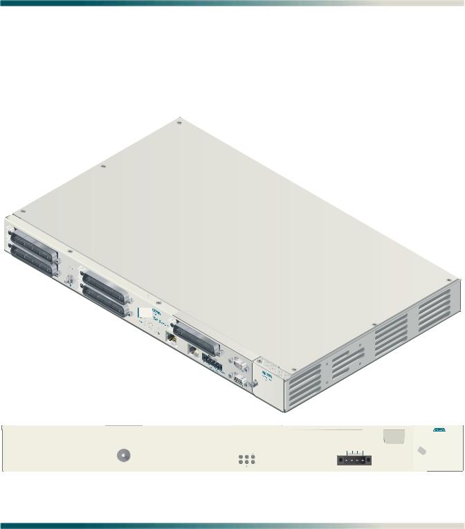
The Total Access 1248 (see Figure 1-1) is a Digital Subscriber Line Access Multiplexer (DSLAM) system that is used to further extend Asymmetrical Digital Subscriber Line (ADSL) services in the network.
5  7
7
6  8
8
|
|
|
|
|
|
|
|
|
|
|
|
FAN MODULE |
|
|
|
|
|
|
1179641L4 |
|
|
|
|
1179675L1 |
|
|
|
|
|
|
|
|
|
|
|
|
||
|
|
|
|
|
|
|
|
T1/E1 1-8 |
|
A |
B |
ALARM |
|
|
|
|
|
|
5 |
7 |
|
|
-48V RET |
-48V RET |
|
|
|
|
|
|
|
|
|
|
|
|
||
|
|
|
|
|
|
PWR |
|
|
|
|
|
|
|
|
|
|
|
|
ALM |
8 |
|
|
|
|
|
TOP:POTS |
BOTTOM: ADSL+POTS |
PORTS 1-24 |
TOP:POTS |
BOTTOM: ADSL+POTS |
PORTS 25-48 |
6 |
ETHERNET |
EXPANSION |
USE COPPER CONDUCTORS ONLY! |
CRAFT |
||
T1/E1 |
|
OUT |
||||||||||
|
|
|
|
|
|
|
|
-48V .....,5.0A |
|
|||
Figure 1-1. Total Access 1248
61179641L4-5B |
1-1 |

Total Access 1248 Octal T1 IMA DSLAM Installation and Maintenance Practice
DESCRIPTION
The Total Access 1248 is a mini-DSLAM that accepts up to eight T1 network feeds assigned to a single IMA group. Inverse Multiplexing over ATM (IMA) is a technology used to bond multiple (DS1) links into a single data pipe.
The Total Access 1248 provides ADSL2+ service for up to 48 subscribers per unit. Plain Old Telephone Service (POTS) is brought in from an on-board splitter and is placed on the same pair as the ADSL2+ signal. Since ADSL2+ and POTS are transported on the same twisted pair, the subscriber must use a low-pass filter on the line before attempting to use analog services. The lines are configured for service with flow-through provisioning using a network configuration application such as Telcordia’s Network Configuration (NCON). Permanent Virtual Circuits (PVCs) in the ATM network to the subscriber’s chosen Internet Service Provider (ISP) allow the subscriber access to the internet.
The Total Access 1248 is rack-mountable and measures 1.75 inches (1U) high, 17.25 inches wide, and 11.125 inches deep (measurements do not include the mounting brackets). The device may be powered using one or two –48 VDC sources, one for a non-redundant power configuration, two for a redundant power configuration.
For detailed specification information on the Total Access 1248 system, refer to “Section 7, Specifications”.
Features
The Total Access 1248 system incorporates the following features:
•Front panel indication of network, subscriber, and power/self-test status
•48 ports of ADSL2+ plus POTS
•Redundant power inputs
•POTS service is not power dependent
•Removable front-accessible fan module (P/N 1179675L1)
•Supports IMA for up to eight T1/E1 IMA links
•ADSL options provisionable to accommodate both short and long haul T1s
•Provisioning and alarm monitoring via TL1, SNMP, local craft interface, and inband management channel
•IMA group support (one group)
•Operates over an extended temperature range of –40°C to +70°C
•Interoperable with any ATM T1 IMA device built to current IMA specifications, which includes the Total Access 3000 IMA Aggregation System
•Compliant with GR-63-CORE/GR-1089-CORE (NEBS), and Listed to the applicable UL Safety Standard(s)
•Expansion capabilities for a total of three Total Access 1248 Expansion units to a Host unit
•In-band management of the expansion chassis
1-2 |
61179641L4-5B |

Description
Front Panel LEDs
Figure 1-2 shows the location of the Total Access 1248 front panel LEDs. Upon initial powering, the Total Access 1248 system performs a power up self-test. Once the power up self-test is complete, the status LEDs reflect the condition of the hardware.
FAN MODULE
1179675L1
|
1179641L4 |
|
24 |
NDUCTORS ONLY! |
|
.... ,5.0A |
||
|
Figure 1-2. Total Access 1248 Front Panel LEDs
See Table 1-1 for a listing of LEDs and their status.
|
|
Table 1-1. Front Panel LEDs |
|
|
|
|
|
Label |
Status |
Description |
|
|
|
|
|
PWR |
|
Green |
Total Access 1248 is In Service |
|
|
Yellow |
Total Access 1248 is Out of Service-Maintenance |
|
|
Red |
Total Access 1248 Failed self-test |
|
|
Off |
No power present on Total Access 1248 |
|
|
|
|
ALM |
|
Yellow |
Total Access 1248 is reporting a Minor alarm |
|
|
Red |
Total Access 1248 is reporting a Major alarm |
|
|
Off |
No alarms reported on Total Access 1248 |
|
|
|
|
T1/E1 1–8 |
|
Green |
All good |
|
|
Green Flashing |
T1/E1 OK, no IMA Sync |
|
|
Yellow |
Signal present OOF |
|
|
Yellow Flashing |
T1/E1 is in loopback |
|
|
Red |
No signal |
|
|
Off |
Facility unassigned |
|
|
|
|
ETHERNET |
|
Green |
Ethernet signal present |
|
|
Green Flashing |
Ethernet with traffic |
|
|
Yellow |
No signal |
|
|
|
|
EXPANSION OUT |
|
Green |
Connected to a downstream box |
|
|
Green Flashing |
Connected with traffic |
|
|
Yellow |
No signal |
|
|
|
|
61179641L4-5B |
1-3 |

Total Access 1248 Octal T1 IMA DSLAM Installation and Maintenance Practice
Compliance
CAUTION
C A U T I O N !
SUBJECT TO ELECTROSTATIC DAMAGE
OR DECREASE IN RELIABILITY.
HANDLING PRECAUTIONS REQUIRED.
Electrostatic Discharge (ESD) can damage electronic modules. When handling modules, wear an antistatic discharge wrist strap to prevent damage to electronic components. Place modules in antistatic packing material when transporting or storing. When working on modules, always place them on an approved antistatic mat that is electrically grounded.
The Total Access 1248 is NRTL listed to the applicable UL standards. The Total Access 1248 meets or exceeds all the applicable requirements of NEBS, Telcordia GR-63-CORE, and GR-1089-CORE.
The Total Access 1248 is intended for deployment in Central Office type facilities, EEEs, EECs, and locations where the NEC applies. Install the Total Access 1248 in a restricted access location. Table 1-2 shows the compliance codes for the Total Access 1248.
Table 1-2. Compliance Codes
Configuration Codes |
Input |
Output |
|
|
|
Power Code (PC) |
F |
C |
|
|
|
Telecommunication Code (TC) |
X |
X |
|
|
|
Installation Code (IC) |
A |
– |
|
|
|
This device complies with Part 15 of the FCC rules. Operation is subject to the following two conditions:
1.This device may not cause harmful interference.
2.This device must accept any interference received, including interference that may cause undesired operation.
Changes or modifications not expressly approved by ADTRAN could void the user’s authority to operate this equipment.
1-4 |
61179641L4-5B |
Description
CAUTION
Per GR-1089-CORE the Total Access 1248 is designed and intended for installation as part of a Common Bonding Network (CBN). The Total Access 1248 is not designed nor intended for installation as part of an Isolated Bonding Network (IBN).
CAUTION
Per GR-1089-CORE Section 9, the Total Access 1248 is intended to be deployed in either a DC-C (common) or DC-I (isolated) installation of the Total Access 1248.
CAUTION
The Total Access 1248 Chassis frame ground terminal must be connected to a reliable earth ground.
CAUTION
Connect to a reliably grounded –48 VDC source which is electrically isolated from the AC source. The branch circuit overcurrent protection shall be a fuse or circuit breaker rated minimum 48 VDC, maximum 3 amp.
NOTE
The POTS and ADSL+POTS ports are classified as Type 1, 3, and 5 as defined in Appendix B of GR-1089-CORE, Issue 4 and meets the lightning and power fault criteria with any primary protector that meets any of the voltage limits of GR-974-CORE or GR-1361-CORE (i.e., carbon blocks, gas tubes, solid states, etc.). Solid-state primary protectors are not recommended as they could affect the signal integrity of the ADSL.
NOTE
Current limiting protectors are not required.
61179641L4-5B |
1-5 |

Total Access 1248 Octal T1 IMA DSLAM Installation and Maintenance Practice
This page is intentionally blank.
1-6 |
61179641L4-5B |
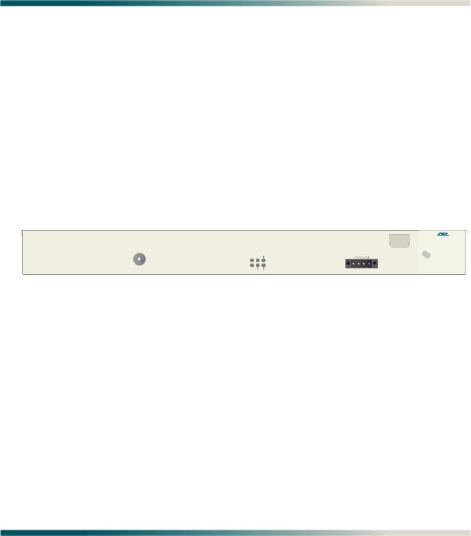
Section 2
Application Guidelines
INTRODUCTION
The Total Access 1248 provides 48 ADSL2+ plus POTS ports downstream to the subscriber, one to eight T1 IMA ports upstream to the network, local and remote management capabilities, and front panel LEDs that indicate status. Figure 2-1 illustrates an operational scenario for the Total Access 1248.
Voice Switch or DLC Providing 1-48 POTS |
Central Office or Remote Terminal |
|
||||
POTS Ports 1-24 |
POTS Ports 25-48 |
Octal IMA Providing 1-8 DS1s |
|
|||
|
|
|
|
|
|
|
|
|
|
|
|
|
|
|
|
|
|
|
|
|
|
|
|
|
|
|
|
|
|
|
|
|
|
|
|
|
|
|
|
|
|
|
|
|
|
|
|
|
|
|
|
|
|
|
|
|
|
|
|
|
|
|
|
|
|
|
|
|
|
|
|
|
|
|
|
|
|
|
|
TOP:POTS BOTTOM: ADSL+POTS |
PORTS 1-24 |
|||
ADSL2+ Plus POTS
To Ground
FAN MODULE
1179675L1
1179641L4
TOP:POTS BOTTOM: ADSL+POTS
POTSPlus
ADSL2+
|
|
|
T1/E1 1-8 |
|
A |
B |
ALARM |
|
5 |
7 |
|
|
-48V RET |
-48V RET |
|
|
|
|
|
|
|
||
|
PWR |
|
|
|
|
|
|
|
ALM |
8 |
|
|
|
|
|
PORTS 25-48 |
6 |
ETHERNET |
EXPANSION |
USE COPPER CONDUCTORS ONLY! |
CRAFT |
||
|
T1/E1 |
|
|
OUT |
-48V .....,5.0A |
|
|
Power
24 Ports |
|
|
|
|
|
|
|
|
|
|
|
|
|
|
|
|
|
|
|
|
|
|
|
|
|
|
|
|
|
|
|
|
|
|
|
|
|
|
|
|
|
|
|
|
|
|
|
24 Ports |
|
|
|
|
|
|
|
|
|
|
|
|
|
|
|
|
|
|
|
|
|
|
|
|
|
|
|
|
|
|
|
|
|
|
|
|
|
|
|
|
|
|
|
|
|
|
|
|
|
|
|
|
|
|
|
|
|
|
|
|
|
|
|
|
|
|
|
|
|
|
|
|
|
|
|
|
|
|
|
|
|
|
|
|
|
|
|
|
|
|
|
|
|
|
|
|
|
|
Subscriber |
Subscriber |
Subscriber |
Subscriber |
Figure 2-1. Total Access 1248 Operational Scenario
61179641L4-5B |
2-1 |

Total Access 1248 Octal T1 IMA DSLAM Installation and Maintenance Practice
EXPANSION
Up to four Total Access 1248 systems can be connected together (see Figure 2-2). One of the units must be a Total Access 1248 host unit (P/N 1179641L4) and the others are Total Access 1248 client units (P/N 1179641L5).
The client units (also referred to as Expansion units) have RJ-45 jacks, labeled EXPANSION IN and EXPANSION OUT, for the purpose of expanding one to another.
The Total Access 1248 host unit provides the network connection for all of the client units. All provisioning for the clients is completed through the host unit.
Beginning with the host, a Category 5e, non-crossover cable is connected from the EXPANSION OUT jack of the host unit to the EXPANSION IN jack of the first client unit. Further connections between client unit EXPANSION OUT jacks to EXPANSION IN jacks continue until a total of up to three client units have been connected with the third client unit having only a connection to the EXPANSION IN jack.
Host
|
|
|
|
|
|
|
|
|
|
|
|
FAN MODULE |
|
|
|
|
|
|
1179641L4 |
|
|
|
|
1179675L1 |
|
|
|
|
|
|
|
|
|
|
|
|
||
|
|
|
|
|
|
|
|
T1/E1 1-8 |
|
A |
B |
ALARM |
|
|
|
|
|
|
5 |
7 |
|
|
-48V RET |
-48V RET |
|
|
|
|
|
|
|
|
|
|
|
|
||
|
|
|
|
|
|
PWR |
|
|
|
|
|
|
|
|
|
|
|
|
ALM |
8 |
|
|
|
|
|
TOP:POTS |
BOTTOM: ADSL+POTS |
PORTS 1-24 |
TOP:POTS |
BOTTOM: ADSL+POTS |
PORTS 25-48 |
6 |
ETHERNET |
EXPANSION |
USE COPPER CONDUCTORS ONLY! |
CRAFT |
||
T1/E1 |
|
OUT |
||||||||||
|
|
|
|
|
|
|
|
-48V .....,5.0A |
|
|||
Client 1
FAN MODULE
1179675L1
1179641L5
A B
-48V RET -48V RET
PWR |
ALM |
TOP:POTS BOTTOM: ADSL+POTS |
PORTS 1-24 |
TOP:POTS BOTTOM: ADSL+POTS |
PORTS 25-48 |
EXPANSION |
|
EXPANSION |
USE COPPER CONDUCTORS ONLY! |
CRAFT |
|
|
|
|
IN |
|
OUT |
-48V .....,5.0A |
|
Client 2
FAN MODULE
1179675L1
1179641L5
A B
-48V RET -48V RET
PWR
ALM
TOP:POTS BOTTOM: ADSL+POTS |
PORTS 1-24 |
TOP:POTS BOTTOM: ADSL+POTS |
PORTS 25-48 |
EXPANSION |
|
EXPANSION |
USE COPPER CONDUCTORS ONLY! |
CRAFT |
IN |
|
OUT |
-48V .....,5.0A |
|
||||
|
|
|
|
|
|
Client 3
FAN MODULE
1179675L1
1179641L5
A B
-48V RET -48V RET
PWR
ALM
TOP:POTS BOTTOM: ADSL+POTS |
PORTS 1-24 |
TOP:POTS BOTTOM: ADSL+POTS |
PORTS 25-48 |
EXPANSION |
|
EXPANSION |
USE COPPER CONDUCTORS ONLY! |
CRAFT |
|
|
|
|
IN |
|
OUT |
-48V .....,5.0A |
|
Figure 2-2. Expansion Cabling
2-2 |
61179641L4-5B |

Section 3
Installation
INTRODUCTION
C A U T I O N !
SUBJECT TO ELECTROSTATIC DAMAGE
OR DECREASE IN RELIABILITY.
HANDLING PRECAUTIONS REQUIRED.
CAUTION
Electrostatic Discharge (ESD) can damage electronic units. When handling units, wear an antistatic discharge wrist strap to prevent damage to electronic components. Place units in antistatic packing material when transporting or storing. When working on units, always place them on an approved antistatic mat that is electrically grounded.
After unpacking the Total Access 1248, inspect it for damage. If damage has occurred, file a claim with the carrier and then contact ADTRAN Customer Service. Refer to “Appendix A, Warranty” for further information. If possible, keep the original shipping container to return the Total Access 1248 for repair or for verification of shipping damage.
61179641L4-5B |
3-1 |

Total Access 1248 Octal T1 IMA DSLAM Installation and Maintenance Practice
Shipping Contents
The shipping container for the Total Access 1248 includes the contents shown in Table 3-1.
Table 3-1. Total Access 1248 Shipping Contents
Description |
Part Number |
Quantity |
|
|
|
Total Access 1248 Octal T1 IMA DSLAM |
1179641L4 |
1 |
|
|
|
Total Access 1248 Octal T1 IMA DSLAM Installation and |
61179641L4-5 |
1 |
Maintenance Practice |
|
|
|
|
|
Cable Assembly, Ground Wire |
3125P037@ |
1 |
|
|
|
Terminal Block |
32024CON10 |
1 |
|
|
|
Mounting Bracket, 19-inch |
3265540 |
2 |
|
|
|
Mounting Bracket, 23-inch |
3265541 |
2 |
|
|
|
Screw, 8-32 × 1/4 |
3276003007 |
4 |
|
|
|
Screw, 8-32 × 3/16 |
327611034 |
4 |
|
|
|
Cable Tie |
3292032 |
5 |
|
|
|
Required Tools
The following tools and materials are required to install the Total Access 1248:
•Wire-wrap tool
•#2 phillips-head screwdriver
•#1 phillips-head screwdriver
•Straight-slot screwdriver
•Multimeter (ohmmeter and voltmeter)
•Crimping tool for power lugs
•Wire strippers
•Side cutters
3-2 |
61179641L4-5B |

Installation Prerequisites
INSTALLATION PREREQUISITES
The following items should be completed prior to installing the Total Access 1248:
1.Make sure that the network feed is in place.
2.Make sure that local power is available and that the required fuses are installed.
CAUTION
The maximum power draw for the Total Access 1248 system is 75 watts.
ADTRAN recommends an external fuse rated at 3.0 amps.
3.Complete Table 3-2 with the information that is needed to turn-up and provision the Total Access 1248.
Table 3-2. Turn-up and Provisioning Prerequisite information
Item Description |
Value |
|
|
Network Feed/Aggregation System IP Address
Network Feed/Aggregation System Port
Total Access 1248 IP Address
Total Access 1248 Default Gateway
Total Access 1248 Subnet Mask
Total Access 1248 VPI/VCI
Number of Network Facilities Feeding the Total Access 1248
CLEI Code/System Name
61179641L4-5B |
3-3 |

Total Access 1248 Octal T1 IMA DSLAM Installation and Maintenance Practice
INSTALLATION STEPS
The following steps are required to install the Total Access 1248. Each step has an associated procedure which is referenced below the step. Each procedure provides detailed information for completing the step.
1.Mount the Total Access 1248 system with the appropriate hardware.
For detailed information, refer to “Mounting the Total Access 1248” on page 3-5.
2.Ground the Total Access 1248.
For detailed information, refer to “Ground Connection” on page 3-8.
3.Make the power connections to the Total Access 1248.
For detailed information, refer to “Power Connection” on page 3-9.
4.Connect the Ethernet cable to the Total Access 1248.
For detailed information, refer to “Ethernet Connection” on page 3-11.
5.Connect the DB-15 male alarm cable connector to the Total Access 1248 and wire-wrap the connections to an alarm panel.
For detailed information, refer to “Alarm Connections” on page 3-12.
6.Connect the network cable.
For detailed information, refer to “Network Connections” on page 3-13.
7.Connect the ADSL2+ plus POTS and POTS cables.
For detailed information, refer to “ADSL2+ Plus POTS Connections” on page 3-14.
8.Turn-up the Total Access 1248.
For detailed information, refer to “Quick Turn-up Steps” on page 3-19.
3-4 |
61179641L4-5B |

Installation Steps
Mounting the Total Access 1248
The Total Access 1248 is shipped with two sets of mounting brackets that accommodate either
a19-inch or 23-inch rack.
•The mounting brackets used for a 19-inch rack are part number 3265540.
•The mounting brackets used for a 23-inch rack are part number 3265541.
The mounting brackets provide for flush or mid-mounting configurations. Figure 3-1 shows the Total Access 1248 mounting bracket installation options. Four screws (supplied with the unit) are required for mounting the brackets to the system.
19-inch Mounting Brackets
1 
 3
3
5
2
4  T1/E16
7
8
BACK 


 FRONT
FRONT 

P/N 3265540
23-inch Mounting Brackets
1 
 3
3
5
2
4  T1/E16
7
8
FRONT |
BACK |
|
P/N 3265541
Figure 3-1. Mounting Brackets
61179641L4-5B |
3-5 |
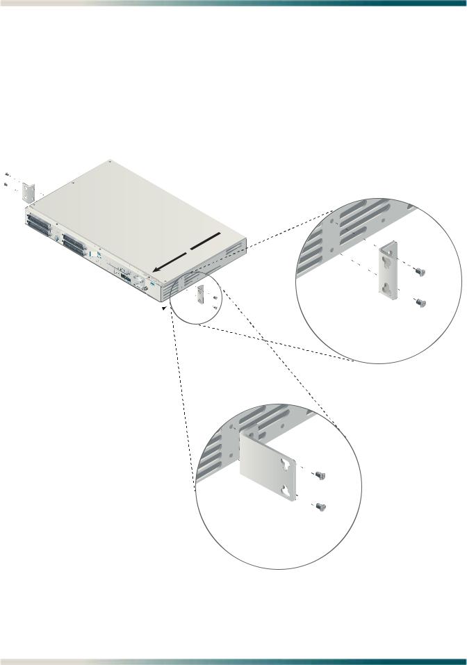
Total Access 1248 Octal T1 IMA DSLAM Installation and Maintenance Practice
Flush-mount
For flush-mount systems, the Total Access 1248 must be mounted from the front of the rack, with mounting brackets in the flush-mounting orientation (see Figure 3-2). When flushmounting a Total Access 1248 in the rack, use a #2 phillips-head screwdriver and attach the mounting brackets to the front screw holes with the flanges containing the slotted rackmounting holes facing the front of the Total Access 1248.
Using four screws appropriate for the mounting rack and the appropriate screwdriver, secure the Total Access 1248 in place on the rack.

 5
5
6
7
8
BACK 


 FRONT
FRONT 

Flush-mount Orientation
Mounting Brackets
23-inch Mounting Brackets
Figure 3-2. Flush-mount Orientation
3-6 |
61179641L4-5B |
Loading...