

Page 1

ADT-CNC4640
CNC4640M Milling Machine Control System
Programming Manual
Adtech (Shenzhen) Technology Co., Ltd.
Add: F/5, Bldg/27-29, Tianxia IC Industrial Park, Yiyuan Rd, Nanshan District,
Shenzhen Postal code: 518052
Tel: 0755-26722719 Fax: 0755-26722718
E-mail:
adtcnc@machine-controller.com http://www.machine-controller.com
Page 2

CNC4640 Programming Manual
Copyright
Adtech (Shenzhen) Technology Co., Ltd. (Adtech hereafter) is
in possession of the copyright of this manual. Without the
permission of Adtech, the imitation, copy, transcription and
translation by any organization or individual are prohibited. This
manual doesn’t contain any assurance, stance or implication in
any form. Adtech and the employees are not responsible for any
direct or indirect data disclosure, profits loss or cause
termination caused by this manual or any information about
mentioned products in this manual. In addition, the products and
data in this manual are subject to changes without prior notice.
All rights reserved.
Adtech (Shenzhen) Technology Co., Ltd.
II
Page 3

Version History
Item No. First uploaded on Version No. Pages Compiled by Typeset by
XT20100819 2011-3-01 A0101 81 Yang Jipeng Yang Jipeng
XT20100819 2011-10-12 A0201 91 Yang Jipeng Yang Jipeng
Revision
Date Version/Page Result Confirmed by
III
Page 4

CNC4640 Programming Manual
Remark:
We have collated and checked this Manual strictly, but we can’t ensure that there are no error and omission in
this Manual.
Due to constant improvement of product functions and service quality, any products and software described in
this manual and the content of the manual are subject to changes without prior notice.
IV
Page 5

Adtech (Shenzhen) Technology Co., Ltd. Contents
Contents
1. Operating procedures of CNC machine tool ....................................................................1-1
2. Identifying the machine tool...............................................................................................2-2
2.1 Motion direction naming of control axes......................................................................................................................... 2-2
2.2 Coordinate systems of machine tool and workpiece........................................................................................................ 2-3
3. Preparation functions..........................................................................................................3-4
3.1 Modal and non-modal function ....................................................................................................................................... 3-4
3.2 Standard G codes list....................................................................................................................................................... 3-4
4. CNC program structure .....................................................................................................4-1
4.1 Program structure ............................................................................................................................................................ 4-1
4.2 Main program and subroutine.......................................................................................................................................... 4-3
5. Position instructions............................................................................................................5-1
5.1 Programming mode instruction ....................................................................................................................................... 5-1
6. Feeding, rapid traverse, interpolation function (G00-G03, G17-G19)...........................6-2
6.1 Feeding............................................................................................................................................................................ 6-2
6.2 Rapid positioning (G00).................................................................................................................................................. 6-2
6.3 Linear interpolation (G01)............................................................................................................................................... 6-3
6.4 Plane selection (G17-G19) .............................................................................................................................................. 6-3
6.5 Arc interpolation (G02, G03)........................................................................................................................................... 6-4
7. Pause instruction (G04) ......................................................................................................7-7
8. Coordinate system setting function (G52-G59, G591-G599, G92)..................................8-2
8.1 Machine tool coordinate system (G53)............................................................................................................................ 8-2
8.2 Workpiece coordinate system.......................................................................................................................................... 8-2
8.2.1 Programmable workpiece coordinate system (G92) ............................................................................................. 8-3
8.2.2 Using preset workpiece coordinate system (G54~G59, G591~G599).................................................................. 8-3
8.3 Local coordinate system (G52)........................................................................................................................................ 8-4
8.4 Operation related to reference point ................................................................................................................................ 8-5
8.4.1 Auto return to reference point (G28) .................................................................................................................... 8-5
8.4.2 Auto return from reference point (G29)................................................................................................................ 8-6
8.4.3 Reference point return checking (G27)................................................................................................................. 8-7
9. Tool compensation function................................................................................................9-1
9.1 Tool compensation........................................................................................................................................................... 9-1
9.2 Tool length compensation................................................................................................................................................ 9-1
9.3 Tool radius compensation................................................................................................................................................ 9-2
9.3.1 Tool radius compensation action .......................................................................................................................... 9-3
9.3.2 Other instructions and actions during tool radius compensation........................................................................... 9-8
9.3.3 G41/G42 instruction and I, J, K designation....................................................................................................... 9-14
9.3.4 Insertion treatment during tool radius compensation.......................................................................................... 9-18
9.3.5 Notes for tool radius compensation.................................................................................................................... 9-20
9.3.6 Compensation number change in compensation mode....................................................................................... 9-21
9.3.7 Tool radius compensation start and axis Z cut-in action ..................................................................................... 9-22
10. Hole processing function...................................................................................................10-1
10.1 Standard fixed cycle .................................................................................................................................................... 10-1
10.2 High-speed deep-hole drilling cycle (G73).................................................................................................................. 10-3
10.3 Reverse-threading cycle (G74).................................................................................................................................... 10-5
10.4 Cancel fixed cycle (G80)............................................................................................................................................. 10-5
10.5 Drilling cycle (G81) .................................................................................................................................................... 10-5
10.6 Drilling cycle, rough boring cycle (G82)..................................................................................................................... 10-6
10.7 Deep-hole drilling cycle (G83).................................................................................................................................... 10-7
10.8 Tapping cycle (G84).................................................................................................................................................... 10-7
10.9 Boring cycle (G85)...................................................................................................................................................... 10-8
10.10 Boring cycle (G86).................................................................................................................................................... 10-9
10.11 Boring cycle (G88).................................................................................................................................................... 10-9
10.12 Boring cycle (G89).................................................................................................................................................... 10-9
10.13 Notes for using hole processing fixed cycle ............................................................................................................ 10-10
10.14 Examples of using tool length compensation and fixed cycle ................................................................................. 10-11
11. Auxiliary function .............................................................................................................11-1
11.1 M code......................................................................................................................................................................... 11-1
11.2 Principal axis speed function....................................................................................................................................... 11-2
11.3 Tool function................................................................................................................................................................ 11-3
12. Category B macro function..............................................................................................12-1
12.1 Variable instruction...................................................................................................................................................... 12-1
12.2 Macro program call ..................................................................................................................................................... 12-2
12.2.1 Using macro calling function............................................................................................................................ 12-2
12.2.2 Macro program calling command............................................................................................................................. 12-2
I
Page 6

Contents Adtech (Shenzhen) Technology Co., Ltd.
12.3 Variable........................................................................................................................................................................ 12-6
12.4 Types of variables........................................................................................................................................................ 12-6
12.5 Calculus instruction ..................................................................................................................................................... 12-8
12.6 Control instruction..................................................................................................................................................... 12-12
12.6.1 Conditional instruction ...................................................................................................................................12-12
12.6.2 Cycle conditional instruction.......................................................................................................................... 12-12
12.7 Notes of using macro................................................................................................................................................. 12-14
12.8 Macro variable user parameters system configuration............................................................................................... 12-14
13. CAD function...................................................................................................................13-16
13.1 Function..................................................................................................................................................................... 13-16
13.2 Keywords description................................................................................................................................................ 13-17
13.3 Example..................................................................................................................................................................... 13-17
14. Automatic tool change (ATC) ..........................................................................................14-1
II
Page 7

Adtech (Shenzhen) Technology Co., Ltd. 4. CNC Programming Structure
1. Operating procedures of CNC machine tool
The step of CNC processing follows:
Fig. 1.1 CNC System Operation Flow
Programming:
Draw part drawing and write processing program (manual or CAM software)
Operating machine tool:
Read the program into CNC system, install the workpiece and the tool properly, and operate the tool to
complete the processing task of preset track.
Therefore, programming is the first step of CNC operating, and also the main content of the manual. The
details are in the chapters below.
1-1
Page 8
4. CNC Programming Structure Adtech (Shenzhen) Technology Co., Ltd.
2. Identifying the machine tool
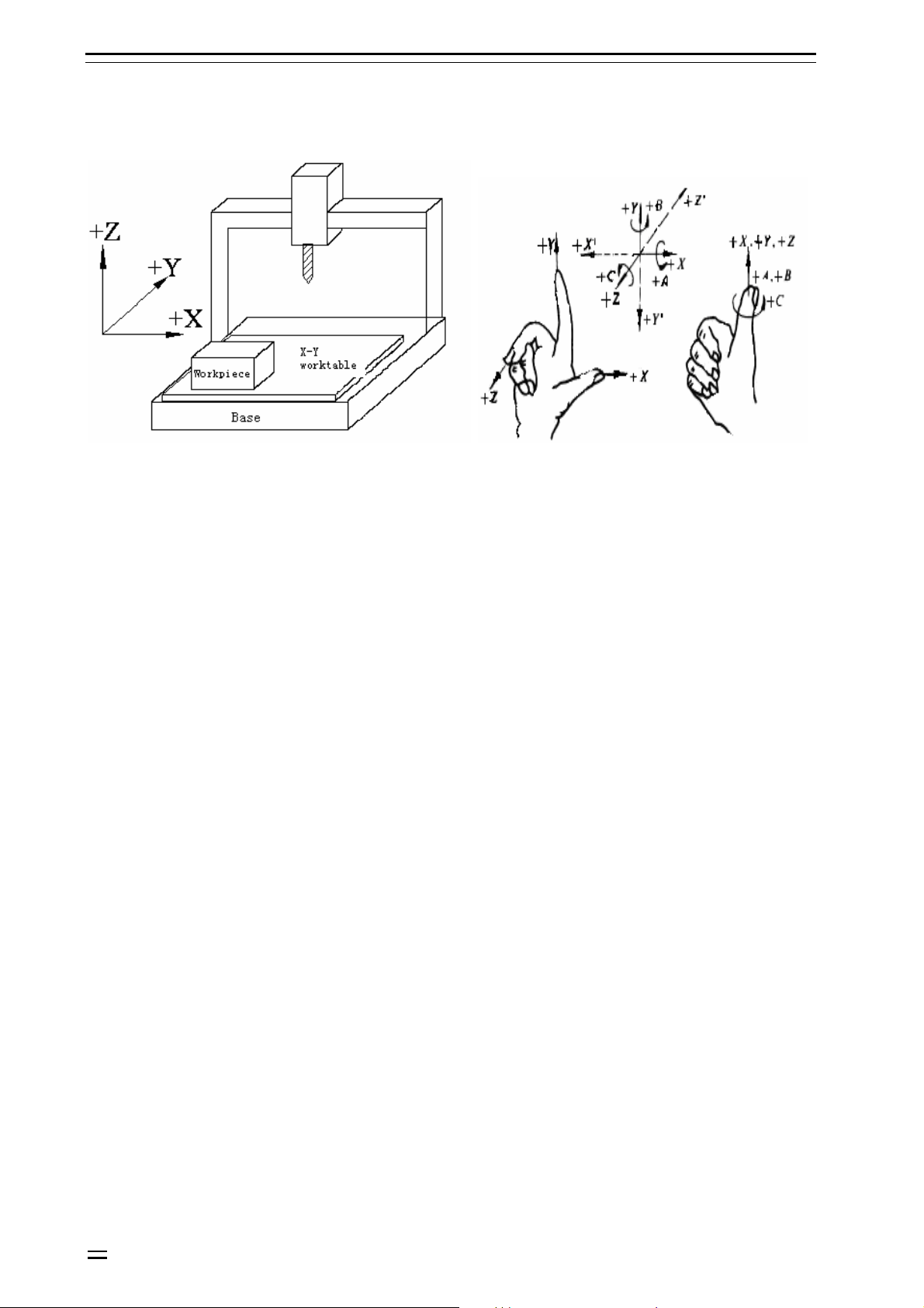
2.1 Motion direction naming of control axes
Fig. 2.1 Name of the machine tool coordinate axis Fig. 2.2 Rotation axis direction determination of the
machine tool
This system can control the rapid traverse, feeding and interpolation of four axes. The axis direction is defined
in Cartesian coordinate system, as shown below (facing to the machine tool):
Z axis:
The up and down movement of the tool relative to the workpiece is Z axis motion, with the upward movement
the positive motion and the downward movement the negative motion.
X axis:
The left and right movement of the tool relative to the workpiece is X axis motion, with the rightward
movement the positive motion and the leftward movement the negative motion.
Y axis:
The forward and backward movement of the tool relative to the workpiece is Y axis motion, with the forward
movement the positive motion and the backward movement the negative motion.
Principal axis:
Look down to the workpiece, the clockwise rotation is principal axis positive rotation and the
counterclockwise rotation is negative rotation.
A, B, C axes:
The positive directions of rotation axes correspond to the positive directions of X, Y, Z axis, which are
determined according to the forward direction of right hand screw.
O Notice:
The X, Y, Z, A, B, C axis motion described in this manual is the tool’s motion relative to the workpiece, i.e. it is assumed
that the workpiece coordinate system has been set.
2-2
Page 9
Adtech (Shenzhen) Technology Co., Ltd. 4. CNC Programming Structure
2.2 Coordinate systems of machine tool and workpiece
Machine tool coordinate system:
The coordinate system fixed on the machine tool is created through returning to reference point after NC is
electrified every time. To select machine tool coordinate system, use G53 instruction.
Workpiece coordinate system:
When start programming, the programmer doesn’t know the position of the workpiece on the machine tool,
and usually uses a point on the workpiece as the reference point to write processing program. The coordinate
system created with this reference point is the workpiece coordinate system. When the workpiece is fixed on
the worktable of the machine tool, move the tool to specified workpiece reference point and set the coordinate
value of this point as the origin of workpiece coordinate system, and the tool will use this workpiece
coordinate system as the reference system and process according to program instruction when the system
executes the machining program. Therefore, the origin offset function of coordinate system is very important
to CNC machine tool.
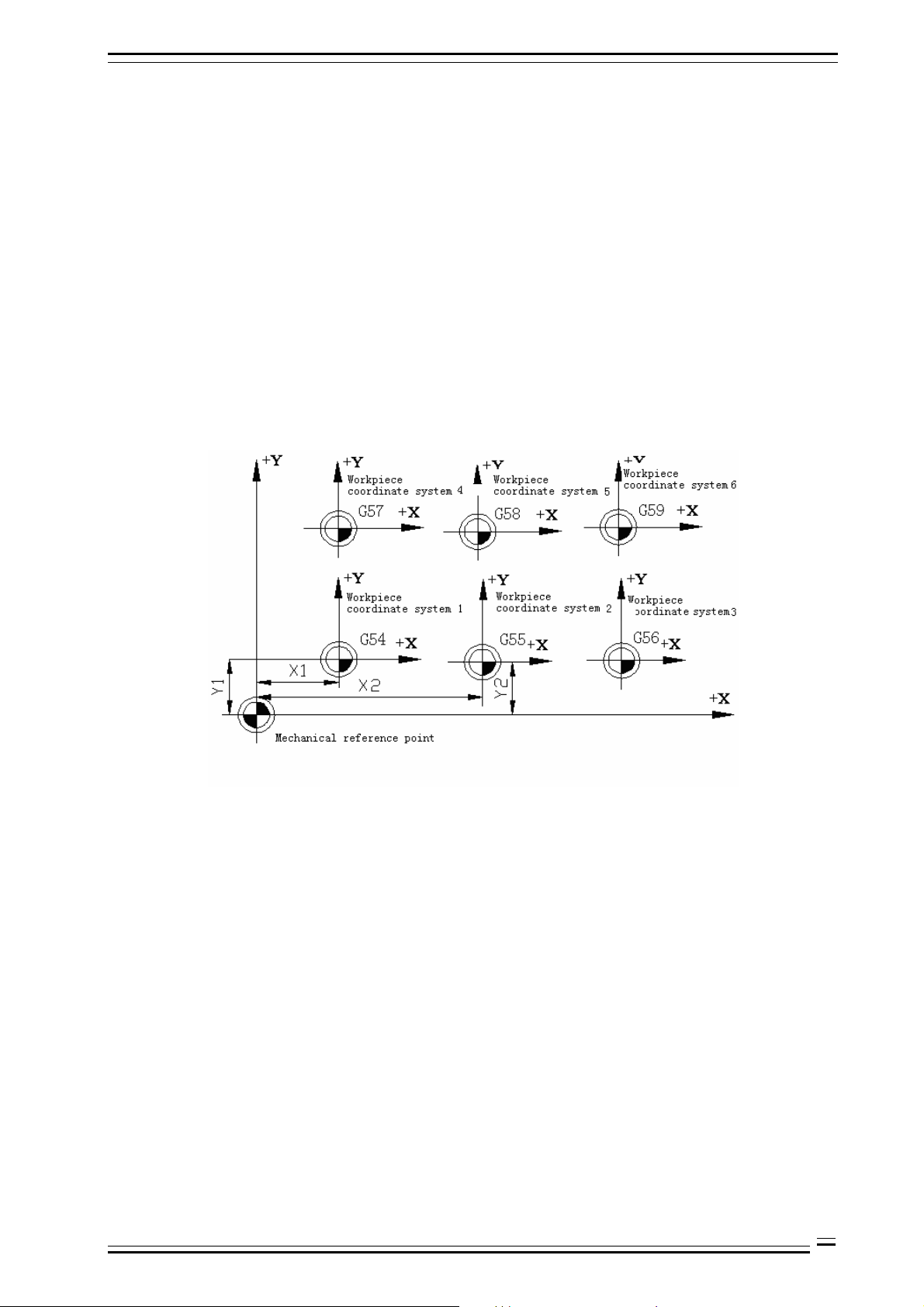
This system can preset six workpiece coordinate systems (nine extended coordinate systems G591-G599 are
added in new version). Set the offset of every workpiece coordinate system origin relative to machine tool
coordinate system origin, and then use G5X (5X is the specific workpiece coordinate system number, the same
below) instruction to select. G5X are nodal instructions, corresponding to 1#~6# preset workpiece coordinate
system respectively.
Fig. 2.3 Workpiece Coordinate System Diagram
2-3
Page 10
4. CNC Programming Structure Adtech (Shenzhen) Technology Co., Ltd.
3. Preparation functions
3.1 Modal and non-modal function
G code determines the function of the command and can be classified into two types:
Non-modal G code:
G code is only valid in defined program segment
Modal G code:
G code is always valid, until next G code of same group appears.
B Example: G01 and G00 are modal G codes
G01X_;
Y_; G01 is valid in this range
Z_;
G00X_;
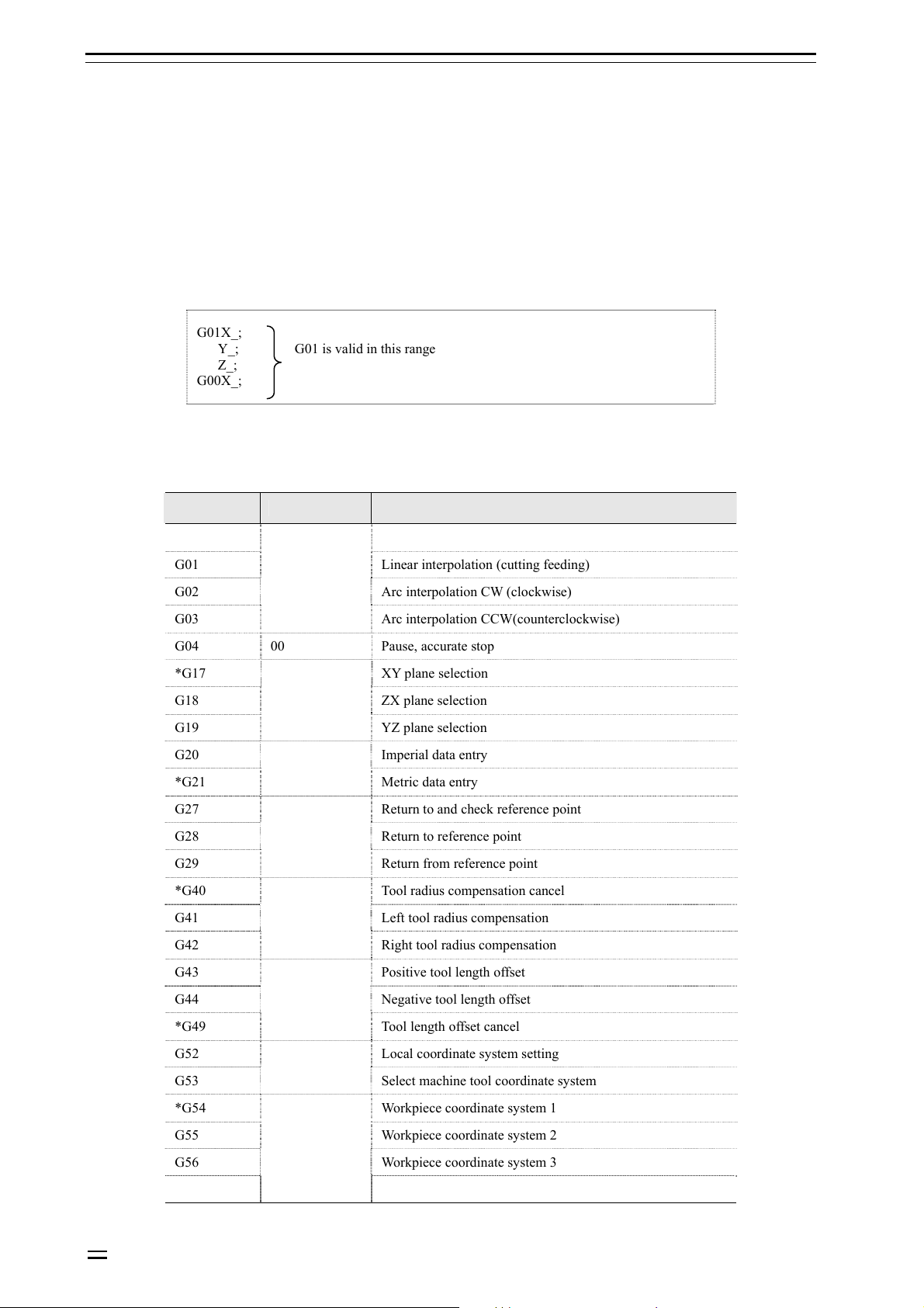
3.2 Standard G codes list
G code Group Function
*G00 Positioning (rapid traverse)
G01 Linear interpolation (cutting feeding)
G02 Arc interpolation CW (clockwise)
G03
G04 00 Pause, accurate stop
*G17 XY plane selection
G18 ZX plane selection
G19
G20 Imperial data entry
*G21
G27 Return to and check reference point
G28 Return to reference point
G29
*G40 Tool radius compensation cancel
G41 Left tool radius compensation
G42
G43 Positive tool length offset
01
Arc interpolation CCW(counterclockwise)
02
YZ plane selection
06
Metric data entry
00
Return from reference point
07
Right tool radius compensation
3-4
G44 Negative tool length offset
*G49
G52 Local coordinate system setting
G53
*G54 Workpiece coordinate system 1
G55 Workpiece coordinate system 2
G56 Workpiece coordinate system 3
G57
08
Tool length offset cancel
00
Select machine tool coordinate system
05
Workpiece coordinate system 4
Page 11
Adtech (Shenzhen) Technology Co., Ltd. 4. CNC Programming Structure
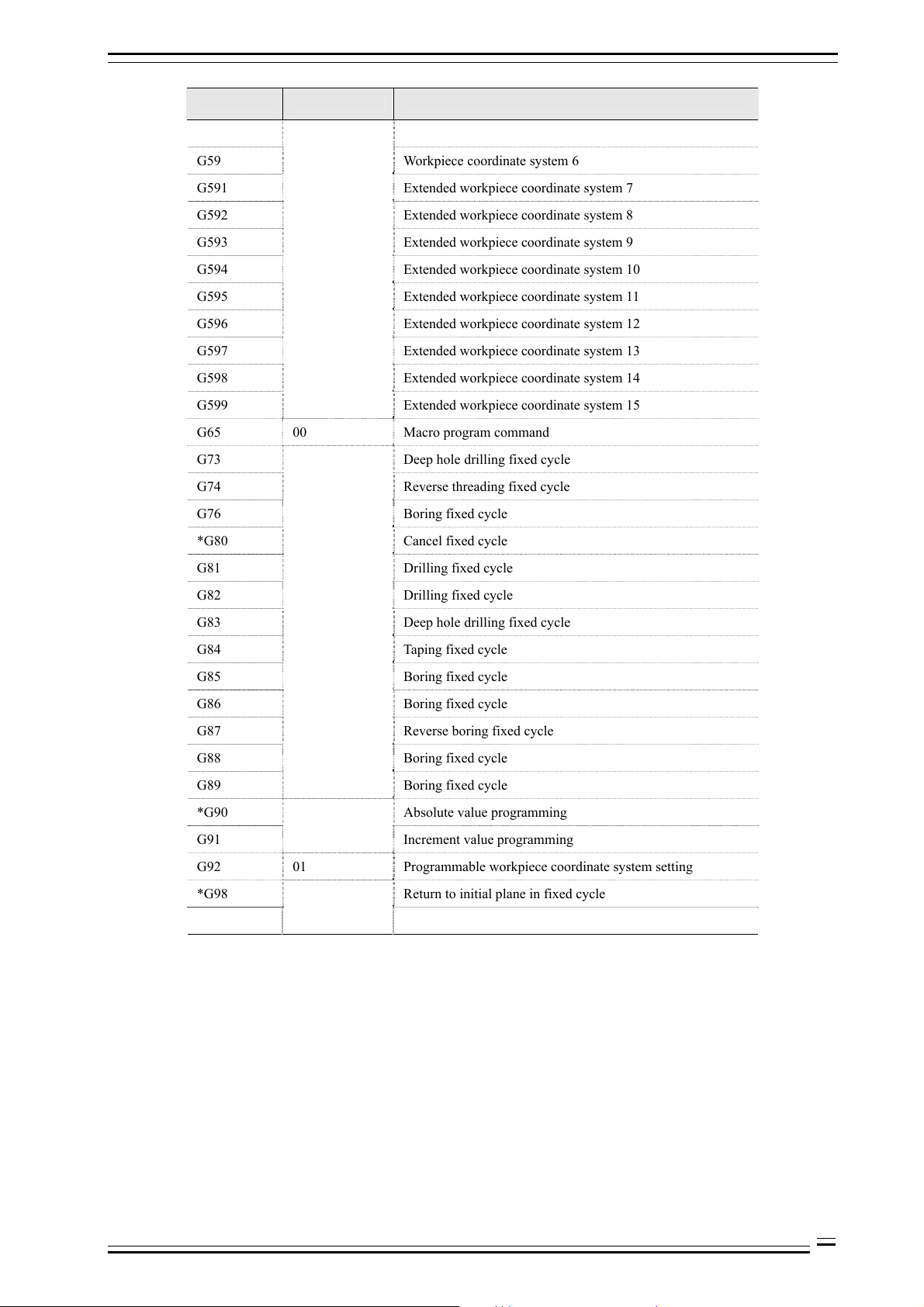
G code Group Function
G58 Workpiece coordinate system 5
G59 Workpiece coordinate system 6
G591 Extended workpiece coordinate system 7
G592 Extended workpiece coordinate system 8
G593 Extended workpiece coordinate system 9
G594 Extended workpiece coordinate system 10
G595 Extended workpiece coordinate system 11
G596 Extended workpiece coordinate system 12
G597 Extended workpiece coordinate system 13
G598 Extended workpiece coordinate system 14
G599 Extended workpiece coordinate system 15
G65 00 Macro program command
G73 Deep hole drilling fixed cycle
G74 Reverse threading fixed cycle
G76 Boring fixed cycle
*G80 Cancel fixed cycle
G81 Drilling fixed cycle
G82 Drilling fixed cycle
G83 Deep hole drilling fixed cycle
G84 Taping fixed cycle
G85 Boring fixed cycle
G86 Boring fixed cycle
G87 Reverse boring fixed cycle
G88 Boring fixed cycle
G89
*G90 Absolute value programming
G91
G92 01 Programmable workpiece coordinate system setting
*G98 Return to initial plane in fixed cycle
G99
09
Boring fixed cycle
03
Increment value programming
10
Return to point R plane in fixed cycle
O Notice:
The items marked with * are the default modal values of G codes of the system;
3-5
Page 12
Adtech (Shenzhen) Technology Co., Ltd. 4. CNC Programming Structure
4. CNC program structure
4.1 Program structure
CNC processing program consists of the following parts:
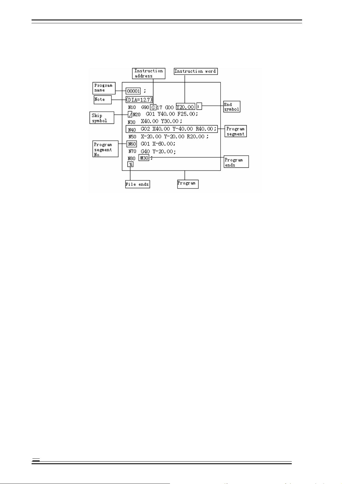
Fig. 4.1 CNC Program Structure Diagram
Program name:
Used to mark different programs, and consists of O and four digits.
Ü If the start of the program doesn’t have program name, the program segment No. of the program start will be
considered as the program name by default;
Ü If the program segment No. contains five digits, the latter four digits will be used as the program name;
Ü If the latter four digits are 0, add 1 automatically to use as the program name;
Ü N0 can’t be used as program name;
Ü When saving the program, if both program name and program segment No. don’t exist, it is necessary to make a
program name through MDI panel.
Note:
The content in the parentheses, in which the user can specify notes, guide, etc.:
Ü The note doesn’t have limit on length; if the program has a long note, the axis motion will pause for a while; therefore,
if a long note is required, please put it at the place that motion pauses or without motion;
Ü If there is only one “)” without “(”, “)” will be ignored;
Ü The note may have multiple lines and are separated with space;
Ü During processing, the note can’t be executed.
Instruction address:
One English letter in the text of the processing program (“Address” hereinafter)
Instruction word:
Adding a number after the instruction address will constitute an instruction word.
Program segment No.:
Consist of letter N and number (≤5 digits), and can be randomly arranged.
Ü The sequence of executing program segments only related to the storage position rather than program segment No.;
Ü If program segment N20 appears before program segment N10, N20 shall be executed first.
Program segment:
A program segment consists of one or several instruction word and ends with “;”;
4-1
Page 13
4. CNC Programming Structure Adtech (Shenzhen) Technology Co., Ltd.
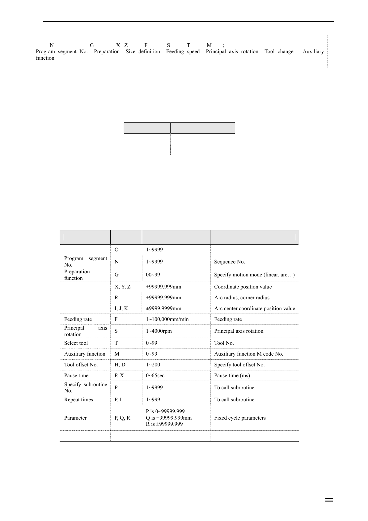
N_ G_ X_ Z_ F_ S_ T_ M_ ;
Program segment No. Preparation Size definition Feeding speed Principal axis rotation Tool change Auxiliary
function
Skip symbol:
If the first character of a program segment is “/”, this program segment is conditional, i.e. skip switch. In upper
position, this program segment isn’t executed; when the skip switch is in lower position, this program segment
is executed.
Program end:
Generally, the following codes are used when program ends:
Code Action
M30 End main program
M99 End subroutine
H Note:
After M30 is executed, CNC stops executing and returns to program start;
After M99 is executed, CNC returns to the program that calls this subroutine and continues executing.
File end:
If the program end doesn’t have %, CNC is reset.
Instruction word is the basic unit of program segment. Every address has unique meaning, and the following
values also have different formats and ranges, as in the Table below:
Table 4.1 Instruction Address and Range of Command Value
Function Address Range Meaning
Program name O 1~9999 Program No.
Program segment
No.
Preparation
function
Size definition
Feeding rate F 1~100,000mm/min Feeding rate
Principal axis
rotation
Select tool T 0~99 Tool No.
Auxiliary function M 0~99 Auxiliary function M code No.
Tool offset No. H, D 1~200 Specify tool offset No.
Pause time P, X 0~65sec Pause time (ms)
Specify subroutine
No.
Repeat times P, L 1~999 To call subroutine
Parameter P, Q, R
N 1~9999 Sequence No.
G 00~99 Specify motion mode (linear, arc…)
X, Y, Z ±99999.999mm Coordinate position value
R ±99999.999mm Arc radius, corner radius
I, J, K ±9999.9999mm Arc center coordinate position value
S 1~4000rpm Principal axis rotation
P 1~9999 To call subroutine
P is 0~99999.999
Q is ±99999.999mm
R is ±99999.999
Fixed cycle parameters
4-2
Page 14
Adtech (Shenzhen) Technology Co., Ltd. 4. CNC Programming Structure
4.2 Main program and subroutine
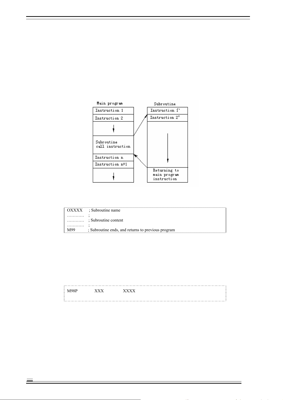
The processing programs include main programs and subroutines. Generally, NC executes the instructions of
main program; however, NC will turn to execute subroutine when executes a subroutine calling instruction,
and will return to the main program when executes the return instruction in subroutine.
When the processing program needs to run same track for several times, edit this track into the subroutine and
save in the program memory of the machine tool, and this subroutine can be called when this track should be
executed in the program.
When the main program calls a subroutine, this subroutine can call another subroutine, which is called double
nesting. Generally, the machine tool allows up to quadruple subroutine nesting. In calling subroutine
instruction, the subroutine can be repeated for 999 times.
Fig. 4.2 Main Program and Subroutine
Subroutine format:
OXXXX ; Subroutine name
………… ;
………… ; Subroutine content
………… ;
M99 ; Subroutine ends, and returns to previous program
B Example: X100.0 Y100.0 M99;
H Note:
Program start should have a subroutine name specified by address O
M99 doesn’t need to appear in a program segment separately.
Subroutine call format:
M98P XXX XXXX
H Note:
In the number following address P, the latter four digits are used to specify the program No. of called subroutine, and the
4-3
former three digits are used to specify the repeat times of calling.
B Example:
M98 P41005; call subroutine 1005, repeat four times
Page 15

4. CNC Programming Structure Adtech (Shenzhen) Technology Co., Ltd.
G90 G00 X-75. Y50. Z53. M98 P40035; this program segment specifies the X, Y, Z axis to fast locate the instruction
position, and then call subroutine 0035 for four times.
H Note:
Ü If the calling time isn’t specified, the subroutine will be called only once;
Ü M98 doesn’t need to appear in a program segment separately;
Ü Different from other M codes, M98 and M99 won’t send signal to the machine tool when executing;
Ü NC gives an alarm if can’t find the program No. specified by address P;
Ü Subroutine call instruction M98 can’t be executed in MDI mode; to execute a subroutine separately, please edit the
following program in the editing mode, and execute in automatic running mode.
O×××;
M98 P××××;
M30;
4-4
Page 16

Page 17
Adtech (Shenzhen) Technology Co., Ltd. 7. Pause Instruction
5. Position instructions
5.1 Programming mode instruction
Function:
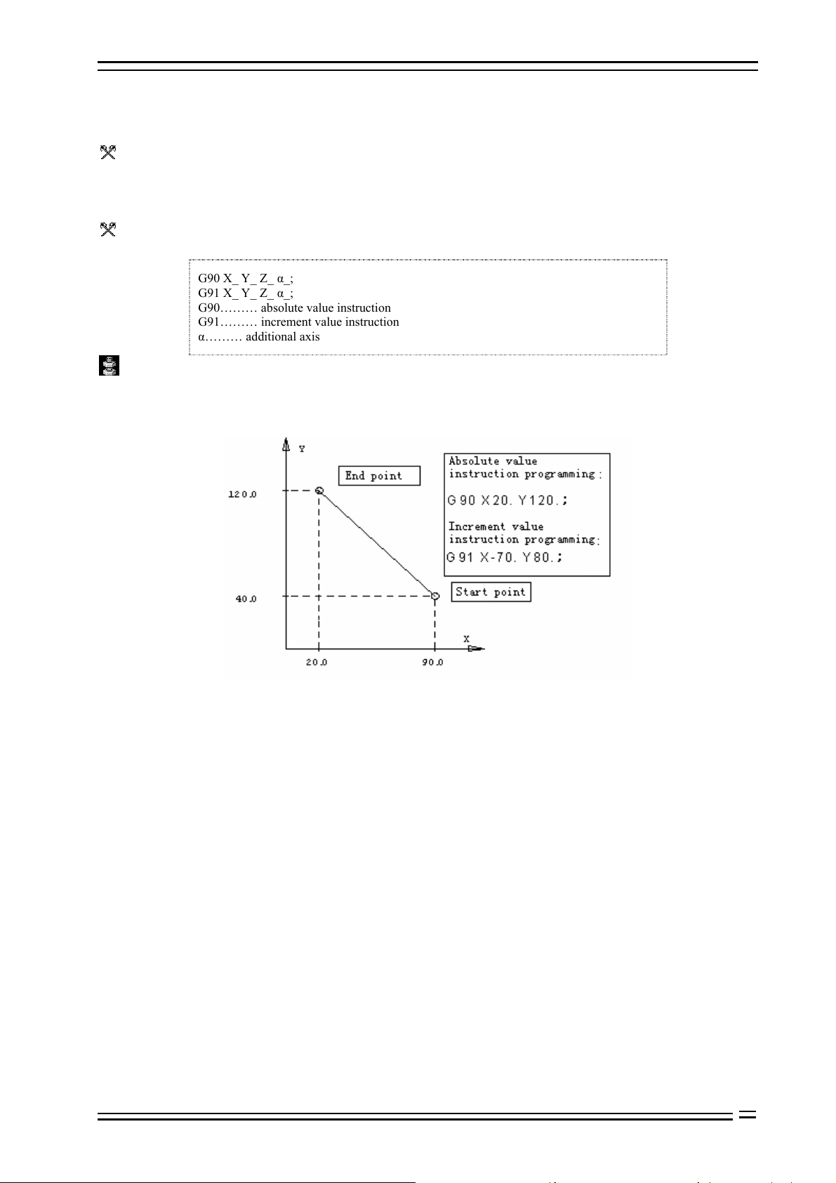
Tool motion instructions include absolute value instruction and increment value instruction. In absolute value
instruction mode, the coordinate value of the motion end in current coordinate system is specified; in
increment value instruction, the distance of every coordinate axis relative to the start point motion is specified.
Format:
G90 X_ Y_ Z_ α_;
G91 X_ Y_ Z_ α_;
G90……… absolute value instruction
G91……… increment value instruction
α……… additional axis
Details:
In absolute value instruction mode, the tool motion is unrelated to current position, and moves according to the
position of specified workpiece coordinate system;
In increment value instruction, the current position is the start point;
Fig. 1.1 Graphic Description Text
For the instructions from workpiece coordinate system home, absolute value or increment value coordinate instructions are same;
G90 and G91 are modal instructions, and are always valid until next new setting of G90 and G91.
5-1
Page 18
7. Pause Instruction Adtech (Shenzhen) Technology Co., Ltd.
6. Feeding, rapid traverse, interpolation function (G00-G03, G17-G19)
6.1 Feeding
The feeding of CNC machine tool is classified into quick positioning and cutting feeding.
The quick positioning feeding appears in the motion between quick feeding and positioning during manual
rapid traverse and fixed cycle of instruction G00. The speed of quick positioning feeding is specified by
machine tool parameters. During quick positioning feeding, the motions among feeding axes are disrelated,
and move at the rapid traverse speed set by the parameters respectively. Generally, tool track is a broken line or
straight line.
Cutting feeding appears in the processing feeding in G01, G02/03 and fixed cycle, and cutting feeding speed is
specified by address F (unit: mm/min). In processing program, F is a modal value, i.e. original programmed F
value is always valid before a new F value is specified. When CNC system is just electrified, F value is
specified by system parameter. The axes of feeding are in interpolation relation, and the composition of their
motions is cutting feeding motion.
The maximum value of F is controlled by system parameter; if the programmed F value is larger than this
value, the actual feeding cutting speed is also this value.
The cutting feeding speed also can be controlled by the feeding rate switch on the operation panel, and the
actual cutting feeding speed is the product of specified F value and feeding rate. The range of rate is
10%-150%.
6.2 Rapid positioning (G00)
Function:
Every axis moves to specified position at specified fast traverse speed respectively; in absolute coordinate
system, the specified motion end is the coordinate value in current coordinate system; in increment coordinate
system, the motion distance of every coordinate axis relative to start point is specified.
Format:
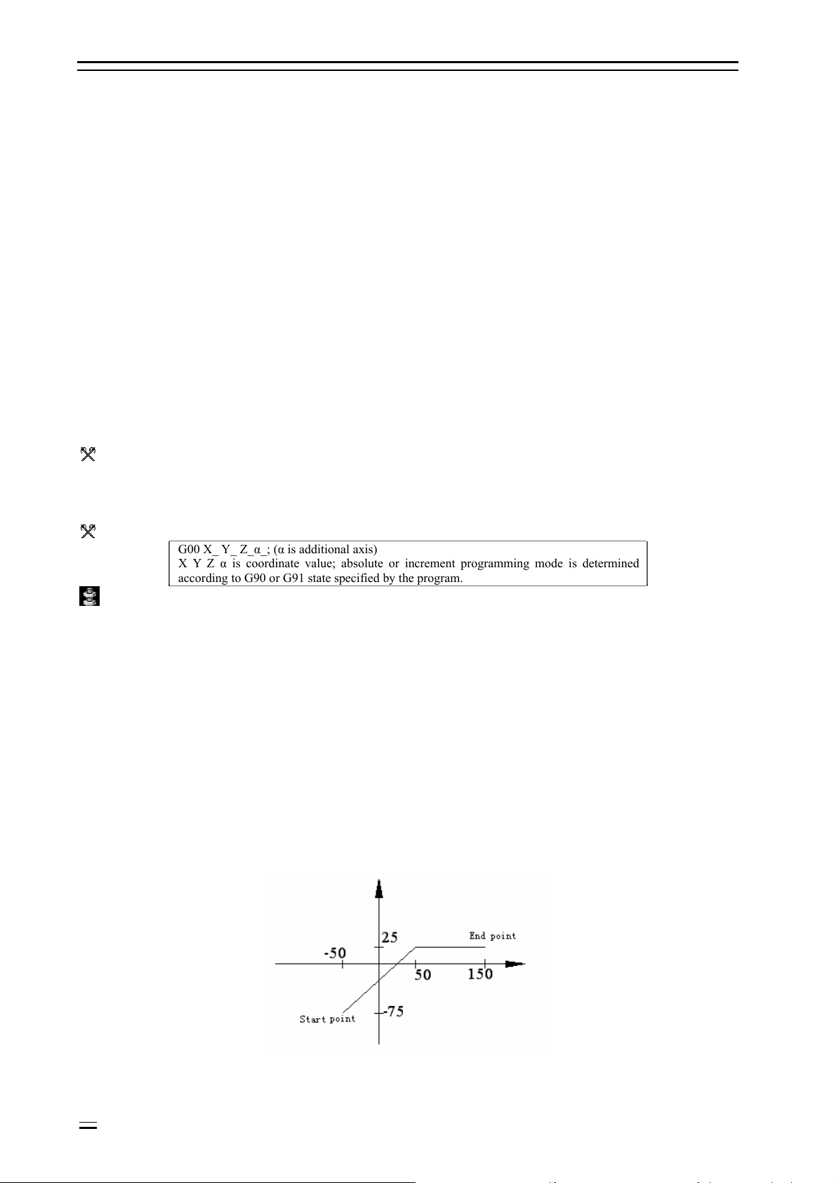
G00 X_ Y_ Z_α_; (α is additional axis)
X Y Z α is coordinate value; absolute or increment programming mode is determined
according to G90 or G91 state specified by the program.
Details:
This instruction changes other G functions; G00 is always valid until the G01, G02 and G03 instructions of same group (01)
appears; when G00 mode is valid, the latter instructions only need to specify coordinate X, Y, Z.
In G00 mode, the tool always accelerates at the start point and decelerates at the end point of every path. It will execute next path
only after the in-place state is confirmed.
When every motion axis reaches the end point, CNC considers that this program segment has ended and turns to next program
segment.
When G00 instruction is valid, the G code function of group 09 (G73-G89) turns into cancellation state (G80).
The motions among different axes are disrelated, i.e. tool path is straight line or broken line (confirmed by selected parameters),
but the positioning time doesn’t change.
Straight line path: same as linear interpolation (G01) mode, the speed is limited by the fast feeding speed of every axis.
Broken line path: every axis is independent and moves for positioning at the maximum speed.
O Notice:
If there is no following number, G will be treated as G00.
B Example:
The position of start point is X-50, Y-75; instruction G00 X150. Y25.; the tool will have the track shown in the
figure below.
6-2
Fig. 6.1 G00 Programming Diagram
Page 19
Adtech (Shenzhen) Technology Co., Ltd. 7. Pause Instruction
6.3 Linear interpolation (G01)
Function:
G01 changes current interpolation state into linear interpolation, tool moves to specified position from current
position, and the track is a straight line from start point to end point.
Format:
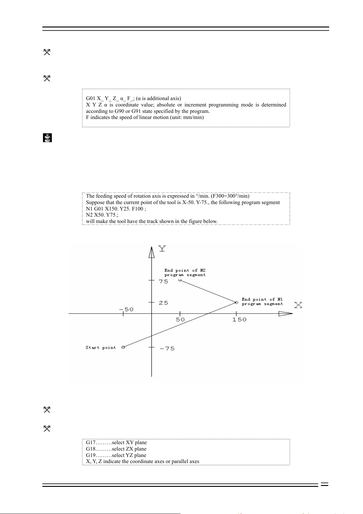
G01 X_ Y_ Z_ α_ F_; (α is additional axis)
X Y Z α is coordinate value; absolute or increment programming mode is determined
according to G90 or G91 state specified by the program.
F indicates the speed of linear motion (unit: mm/min)
Details:
This instruction changes other G functions, and G01 is always valid until G00, G02 or G03 instruction of same
group (01) appears. If the next instruction is still G01 and the feeding speed is same, G01 can be ignored. If the
program segment in which G01 instruction appears for the first time doesn’t have F instruction, there will be
error.
B Example:
The feeding speed of rotation axis is expressed in °/min. (F300=300°/min)
Suppose that the current point of the tool is X-50. Y-75., the following program segment
N1 G01 X150. Y25. F100 ;
N2 X50. Y75.;
will make the tool have the track shown in the figure below.
Fig 6.2 G01 Programming Diagram
6.4 Plane selection (G17-G19)
Function:
This group of instruction is used to select the plane of arc interpolation and tool radius compensation.
Format:
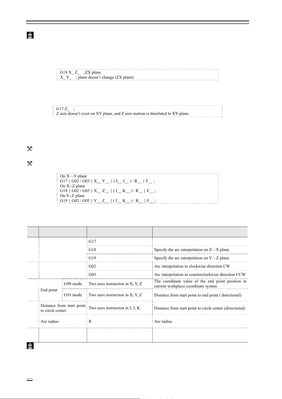
G17………select XY plane
G18………select ZX plane
G19………select YZ plane
X, Y, Z indicate the coordinate axes or parallel axes
6-3
Page 20
7. Pause Instruction Adtech (Shenzhen) Technology Co., Ltd.
Details:
When the system is electrified, plane XY is selected by default.
In the program segment without instruction G17, G18 or G19, the plane doesn’t have any change.
B Example:
B
G18 X_ Z_ ;ZX plane
X_ Y_ ; plane doesn’t change (ZX plane)
Motion instruction is disrelated to plane selection.
B Example:
Under the following instruction,
G17 Z_ ;
Z axis doesn’t exist on XY plane, and Z axis motion is disrelated to XY plane.
About the instructions related to plane selection, please refer to the content related to arc interpolation and tool
compensation instructions.
6.5 Arc interpolation (G02, G03)
Function:
Used to move the tool in arc track
Format:
On X—Y plane
G17 { G02 / G03 } X__ Y__ { ( I__ J__ ) / R__ } F__ ;
On X--Z plane
G18 { G02 / G03 } X__ Z__ { ( I__ K__ ) / R__ } F__ ;
On Y--Z plane
G19 { G02 / G03 } Y__ Z__ { ( J__ K__ ) / R__ } F__ ;
Table 6.1 Arc Interpolation Command Format Description
S/N Data content Instruction Meaning
G17 Specify the arc interpolation on X—Y plane
1 Plane selection
2 Arc direction
G90 mode Two axes instruction in X, Y, Z
3 End point
G91 mode Two axes instruction in X, Y, Z
G18 Specify the arc interpolation on Z—X plane
G19 Specify the arc interpolation on Y—Z plane
G02 Arc interpolation in clockwise direction CW
G03 Arc interpolation in counterclockwise direction CCW
The coordinate value of the end point position in
current workpiece coordinate system
Distance from start point to end point ( directional)
Distance from start point
to circle center
4
Arc radius R Arc radius
5 Feeding rate F The speed of arc motion
Two axes instruction in I, J, K
Distance from start point to circle center (directional)
Details:
G02 (G03) is modal instruction.
The arc crossing multiple quadrants can be specified in one program segment.
6-4
Page 21
Adtech (Shenzhen) Technology Co., Ltd. 7. Pause Instruction
H Note:
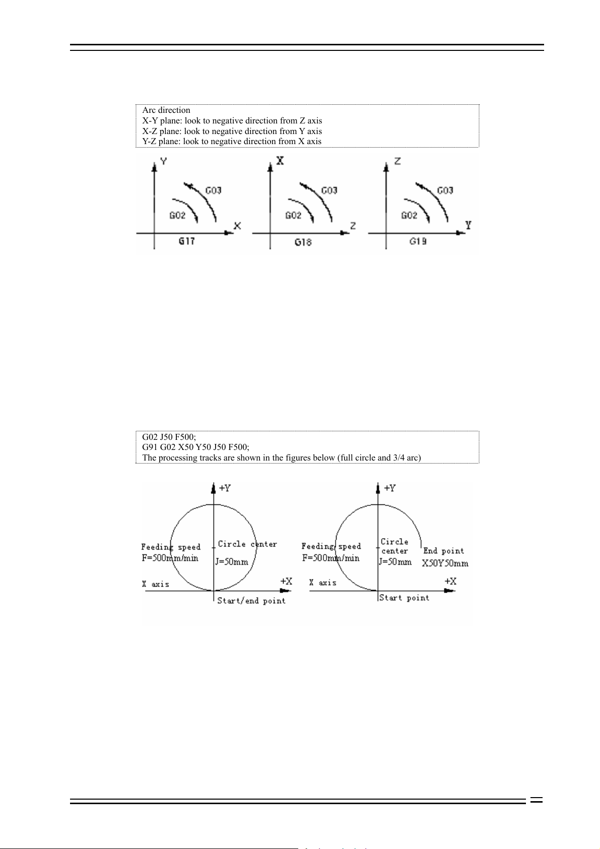
Arc direction
X-Y plane: look to negative direction from Z axis
X-Z plane: look to negative direction from Y axis
Y-Z plane: look to negative direction from X axis
Fig. 6.3 Arc Interpolation Plane Definition Diagram
The end point of the arc is determined by address X, Y and Z. In G90 mode, i.e. absolute value mode, address
X, Y and Z specify the coordinate value of arc end in current coordinate system; in G91 mode, i.e. increment
value mode, address X, Y and Z specify the distance from the point of current tool to the end point in the
direction of every axis.
In X, Y and Z direction, the distance from the point of current point to the circle center is specified by address I,
J and K respectively, the symbols of which are determined by their motion directions.
The coordinate value of arc end can be either in absolute value or increment value, while the coordinate value
of arc center must be increment instruction from the start point.
When X, Y and Z are ignored (the start point coincides with the end point), I, J and K define the circle center,
and the track will be a full circle.
B Example:
G02 J50 F500;
G91 G02 X50 Y50 J50 F500;
The processing tracks are shown in the figures below (full circle and 3/4 arc)
Fig. 6.4 Instruction Diagram of Processing Full Circle
To program a segment of arc, in addition to specifying end point and circle center position, it is also possible
by specifying radius and end point position. If the radius is specified with address R, the value of R can be
either positive or negative; a positive R value can be used to determine an arc smaller than 180°, and a
negative value can be used to determine an arc larger than 180°. Programming a full circle is only possible by
specifying circle center.
6-5
Page 22
7. Pause Instruction Adtech (Shenzhen) Technology Co., Ltd.
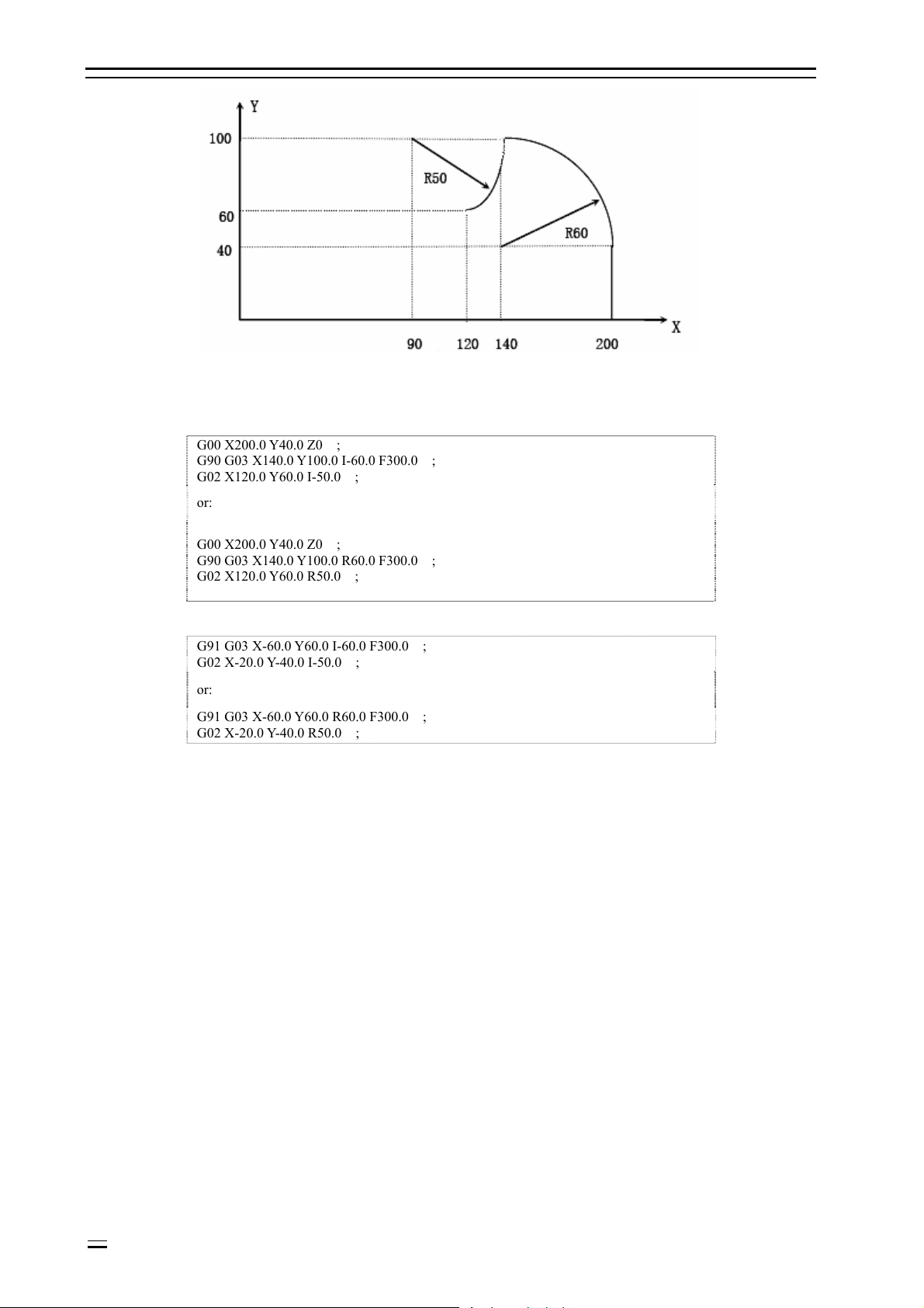
Fig. 6.5 Absolute/Increment Programming Diagram
Above tracks are programmed in absolute value and increment value mode as follows:
Ü Absolute value mode
G00 X200.0 Y40.0 Z0 ;
G90 G03 X140.0 Y100.0 I-60.0 F300.0 ;
G02 X120.0 Y60.0 I-50.0 ;
or:
G00 X200.0 Y40.0 Z0 ;
G90 G03 X140.0 Y100.0 R60.0 F300.0 ;
G02 X120.0 Y60.0 R50.0 ;
Ü Increment mode
G91 G03 X-60.0 Y60.0 I-60.0 F300.0 ;
G02 X-20.0 Y-40.0 I-50.0 ;
or:
G91 G03 X-60.0 Y60.0 R60.0 F300.0 ;
G02 X-20.0 Y-40.0 R50.0 ;
The feeding speed of arc interpolation is specified with F, which is the speed of tool in arc tangent direction.
6-6
Page 23
Adtech (Shenzhen) Technology Co., Ltd. 7. Pause Instruction
7. Pause instruction (G04)
Function:
Pause for a period of time between two program segments.
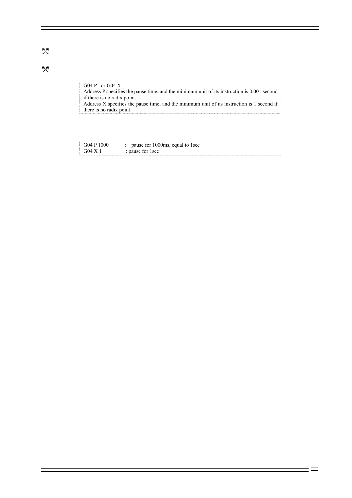
Format:
G04 P_ or G04 X_
Address P specifies the pause time, and the minimum unit of its instruction is 0.001 second
if there is no radix point.
Address X specifies the pause time, and the minimum unit of its instruction is 1 second if
there is no radix point.
B Example:
G04 P 1000 : pause for 1000ms, equal to 1sec
G04 X 1 : pause for 1sec
7-7
Page 24

8. Coordinate System Setting Function Adtech (Shenzhen) Technology Co., Ltd.
8. Coordinate system setting function (G52-G59, G591-G599,
G92)
8.1 Machine tool coordinate system (G53)
Machine tool coordinate system:
The coordinate system fixed on the machine tool is created through returning to reference point after NC is
electrified every time. To select machine tool coordinate system, use G53 instruction.
Format (machine tool coordinate system):
G53 X_Y_Z_;
X_Y_Z_; The coordinate absolute value of every axis
Details:
When the machine tool is electrified, it must be reset in auto or manual mode, and the coordinate system is
created basing on reset reference origin.
The machine tool coordinate system won’t change before the power supply is cut off after created.
The machine tool coordinate system won’t be changed due to G92 instruction.
G53 instruction only can be used in absolute value mode (G90).
G53 is non-modal instruction, and is only valid in current program segment.
If G53 instruction and G28 instruction appear in the same program segment at the same time, the latter
instruction is valid.
When G53 instruction is created, cancel tool radius compensation and tool offset.
All G53 instructions move in quick feeding mode.
The distance between machine tool coordinate system home and machine tool reference point is determined by
the parameters; unless otherwise specified, the reference point of every axis coincides with machine tool
coordinate system home.
8.2 Workpiece coordinate system
Workpiece coordinate system:
When start programming, the programmer doesn’t know the position of the workpiece on the machine tool,
and usually uses a point on the workpiece as the reference point to write processing program. The coordinate
system created with this reference point is the workpiece coordinate system. When the workpiece is fixed on
the worktable of the machine tool, move the tool to specified workpiece reference point and set the coordinate
value of this point as the origin of workpiece coordinate system, and the tool will use this workpiece
coordinate system as the reference system and process according to program instruction when the system
executes the machining program. Therefore, the origin offset function of coordinate system is very important
to CNC machine tool.
8-2
Page 25
Adtech (Shenzhen) Technology Co., Ltd. 7. Pause Instruction
8.2.1 Programmable workpiece coordinate system (G92)
Function:
This instruction creates a new workpiece coordinate system, so that the coordinate value of the point where
current tool locate is the value of IP_ instruction in this workpiece coordinate system. (as shown in Fig. 8.1)
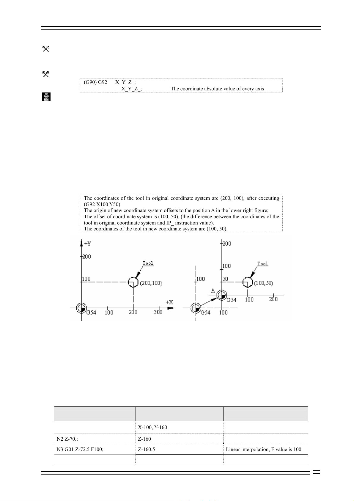
Format:
(G90) G92 X_Y_Z_;
X_Y_Z_; The coordinate absolute value of every axis
Details:
G92 instruction is a non-modal instruction, but the workpiece coordinate system created with this instruction is
modal.
Actually, this instruction also specifies an offset, which is specified indirectly. It is the coordinate value of new
workpiece coordinate system origin in original workpiece coordinate system; seen from G92 function, this
offset is the difference between the coordinate value of the tool in original workpiece coordinate system and
IP_ instruction value. ( as shown in Fig. 8.1)
If G92 instruction is used for several times, the offset specified by G92 instruction will superpose. For every
preset workpiece coordinate system (G54-G59), the superposed offset is valid.
New coordinate system of the part is set in above instruction, e.g. the coordinate value of tool tip is IP_. Once
the coordinates are confirmed, the position of the absolute value instruction is the coordinates in this
coordinate system.
B Example:
The coordinates of the tool in original coordinate system are (200, 100), after executing
(G92 X100 Y50):
The origin of new coordinate system offsets to the position A in the lower right figure;
The offset of coordinate system is (100, 50), (the difference between the coordinates of the
tool in original coordinate system and IP_ instruction value).
The coordinates of the tool in new coordinate system are (100, 50).
Fig. 8.1 G92 Instruction Function Diagram
8.2.2 Using preset workpiece coordinate system (G54~G59, G591~G599)
According to the loading position of the workpiece in the machine tool, this system can preset six coordinate
systems (nine extended in new version); through the operation on LCD panel, set the offset of the origin of
every workpiece coordinate system relative to the origin of machine tool coordinate system, and then use
G54~G59, G591~G599 to select, which are modal instructions, corresponding to 1#~15# preset workpiece
coordinate systems respectively.
B Example:
Preset 1# workpiece coordinate system offset: X-150.000 Y-210.000 Z-90.000
Preset 4# workpiece coordinate system offset: X-430.000 Y-330.000 Z-120.000
Program segment content
N1 G90 G54 G00 X50. Y50.; X-100, Y-160
N2 Z-70.; Z-160
N3 G01 Z-72.5 F100; Z-160.5 Linear interpolation, F value is 100
N4 X37.4; X-112.6 (Linear interpolation)
Coordinates of end point in machine
tool coordinate system
Note
Select 1# coordinate system, quick
positioning
8-3
Page 26
8. Coordinate System Setting Function Adtech (Shenzhen) Technology Co., Ltd.
N5 G00 Z0; Z-90 Quick positioning
N6 X0 Y0 A0; X-150, Y-210
N7 G53 X0 Y0 Z0; X0, Y0, Z0
N8 G57 X50. Y50. ; X-380, Y-280 Select 4# coordinate system
N9 Z-70.; Z-190
N10 G01 Z-72.5; Z-192.5
N11 X37.4; X392.6
N12 G00 Z0; Z-120
N13 G00 X0 Y0 ; X-430, Y-330
Select to use machine tool coordinate
system
Linear interpolation, F value is 100
(modal value)
Seen from above samples, the function of G54~G59 instruction is to move the coordinate origin used by NC to
the point that the coordinates in machine tool coordinate system are preset value; please refer to the operation
section in this manual for the method of presetting.
After returning to the home of machine tool, coordinate systems 1~6 of the workpiece are created. G54 is the
initial mode after electrified. The absolute position of the position screen is the coordinates in current
coordinate system.
In CNC programming of machine tool, unless otherwise specified, the IP of interpolation instruction and other
instructions related to coordinates are the coordinate position in current coordinate system (the coordinate
system used when the instruction is executed). In most cases, the current coordinate system is one of G54~G59,
and machine tool coordinate system are seldom used directly.
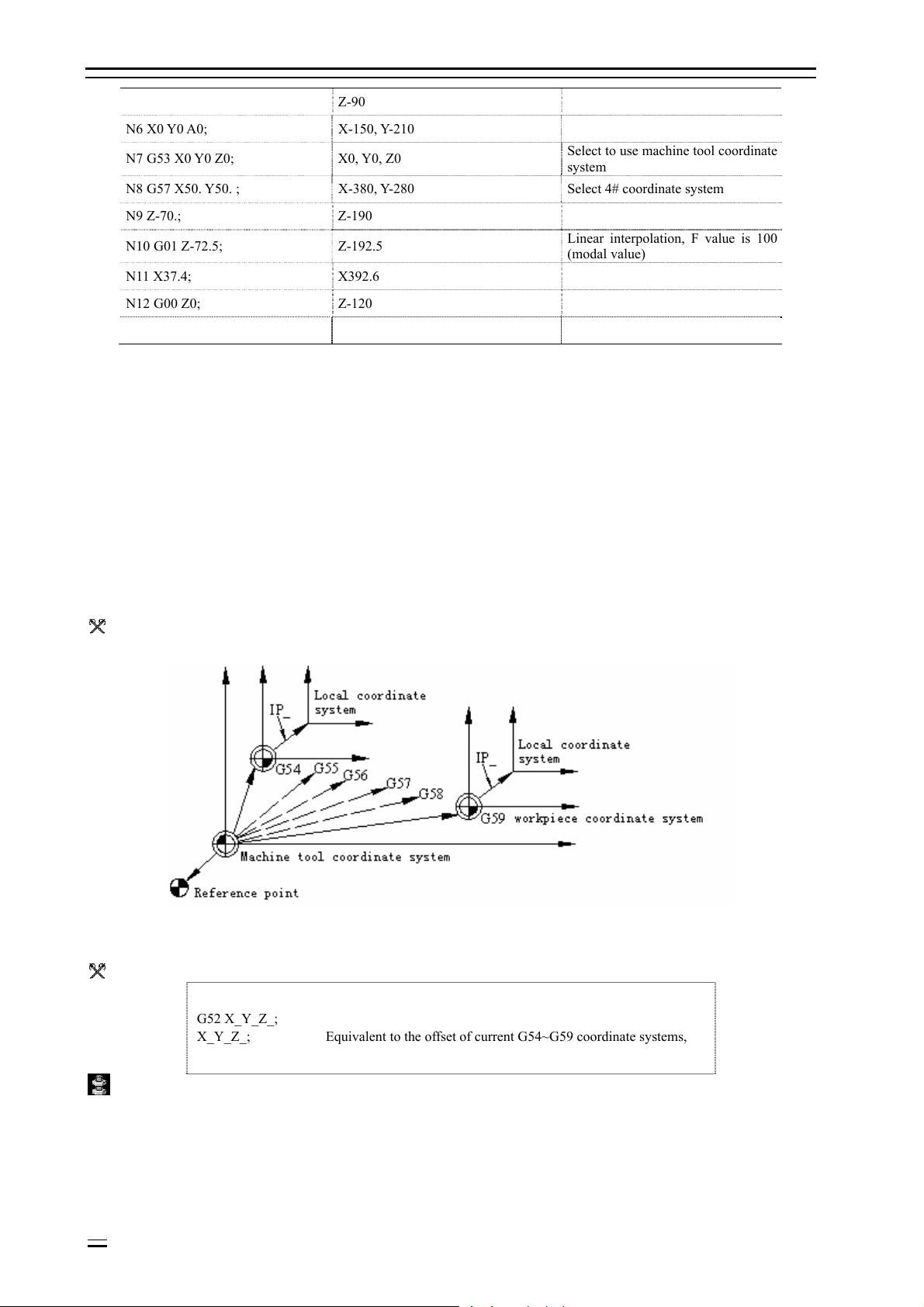
8.3 Local coordinate system (G52)
Function:
G52 can create a local coordinate system, which is a sub-coordinate system equivalent to G54~G59.
Fig. 8.2 Local Coordinate System Diagram
Format:
G52 X_Y_Z_;
X_Y_Z_; Equivalent to the offset of current G54~G59 coordinate systems,
Details:
In this instruction, IP_ specifies the offset equivalent to current G54~G59 coordinate systems, i.e. IP_ specifies
the position coordinates of local coordinate system origin in current G54~G59 coordinate system.
G52 instruction is always valid after specified until next G52 instruction is specified.
G52 instruction can set the processing coordinate system without changing the workpiece coordinate system.
G52 IP0 (G52 X0 Y0 Z 0 α0) can be used to cancel local coordinate system.
8-4
Page 27
Adtech (Shenzhen) Technology Co., Ltd. 7. Pause Instruction
The setting of local coordinate system doesn’t change the machine tool coordinate and workpiece coordinate
system.
G52 instruction can replace G92 instruction to specify the offset between the origin of processing program and
workpiece origin.
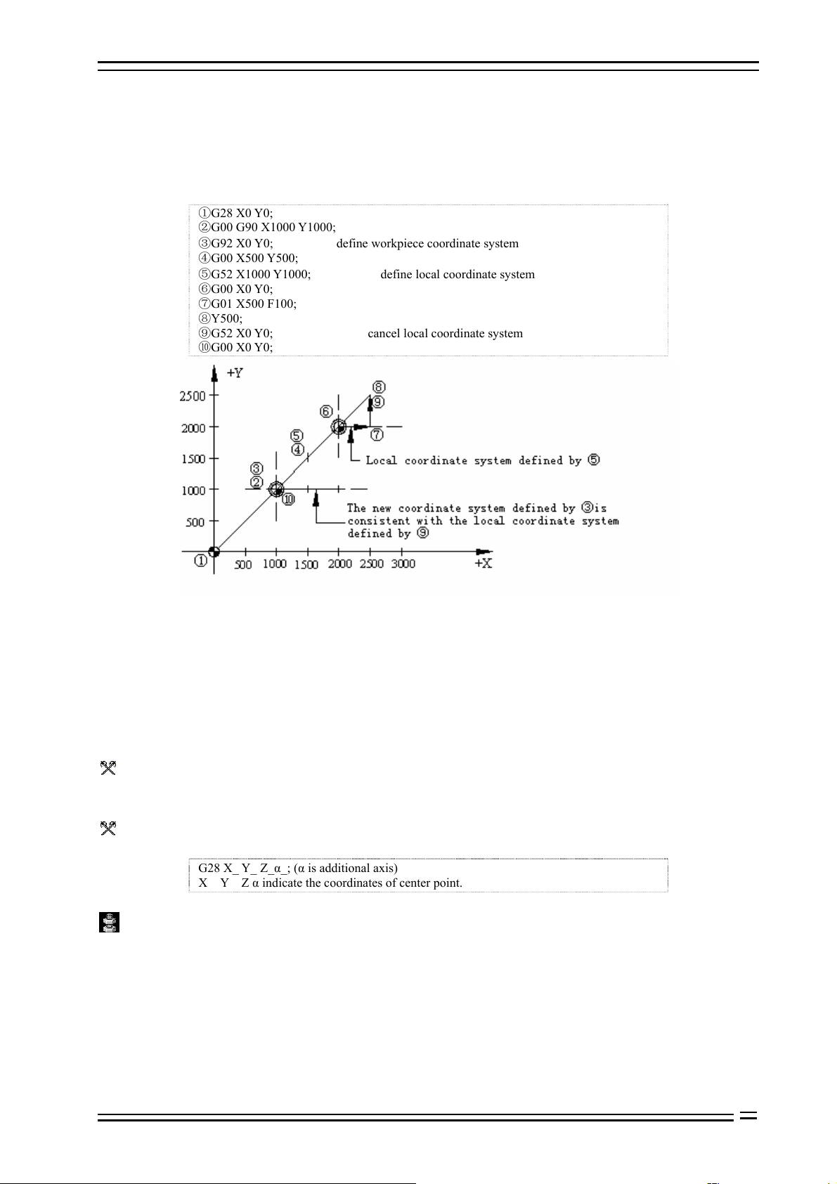
B Example:
Local coordinate system in absolute value mode
G28 X0 Y0;
G00 G90 X1000 Y1000;
③G92 X0 Y0; define workpiece coordinate system
G00 X500 Y500;
⑤G52 X1000 Y1000; define local coordinate system
G00 X0 Y0;
G01 X500 F100;
Y500;
G52 X0 Y0; cancel local coordinate system
G00 X0 Y0;
Fig. 8.3 Local Coordinate System Usage Diagram in Absolute Value Mode
8.4 Operation related to reference point
The machine tool coordinate system is created through returning to reference point after NC is electrified every
time. The reference point is a fixed point on the machine tool, and its position is determined by the installation
position of stopper switch of every axis and the home position of the servo motor of every axis. When this
machine tool returns to the reference point, the coordinates of the reference point in the machine tool
coordinate system is X0, Y0, Z0.
8.4.1 Auto return to reference point (G28)
Function:
This instruction makes the axis return to reference point of the machine tool through the center point specified
by IP at the feeding speed of quick positioning.
Format:
G28 X_ Y_ Z_α_; (α is additional axis)
X Y Z α indicate the coordinates of center point.
Details:
The center point may be specified either in absolute value mode or increment value mode, which depends on
current mode.
Generally, this instruction is used to move the workpiece out of the processing area when the entire processing
program ends, so as to unload processed parts and load the parts to be processed.
When execute G28 instruction before returning to reference point manually, the motion of every started from
center point is same as returning to reference point manually, and the motion direction started from the center
point is positive.
8-5
Page 28
8. Coordinate System Setting Function Adtech (Shenzhen) Technology Co., Ltd.
The coordinates in G28 instruction is saved as center point by NC; on another hand, if an axis isn’t contained
in G28 instruction, the coordinates of the center pointed saved by NC will use the value G28 instruction
specified previously.
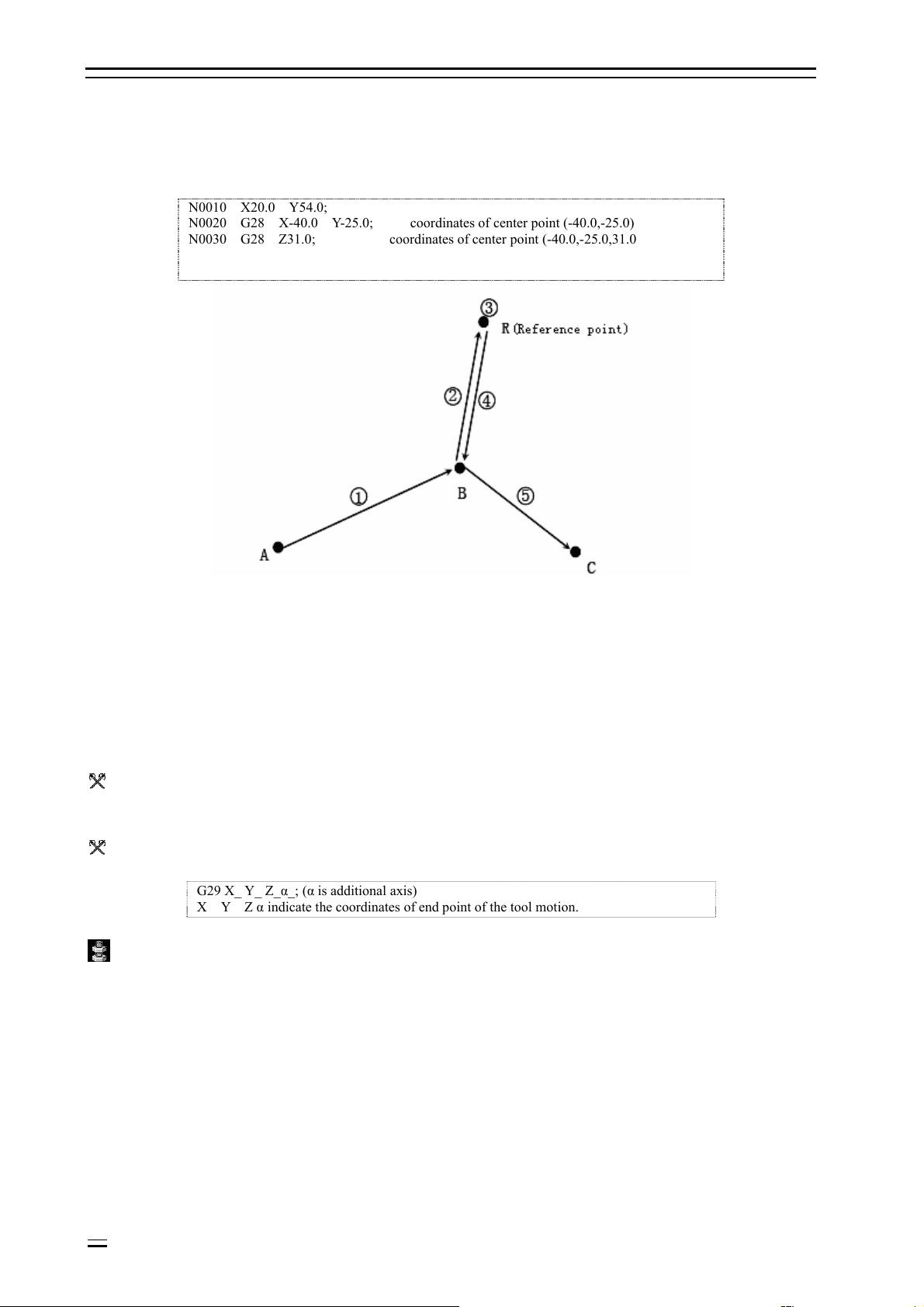
B Example:
N0010 X20.0 Y54.0;
N0020 G28 X-40.0 Y-25.0; coordinates of center point (-40.0,-25.0)
N0030 G28 Z31.0; coordinates of center point (-40.0,-25.0,31.0
Fig. 8.2 Diagram of Automatically Returning to Reference Point
O Notice:
The coordinates of this center point are mainly used by G28 instruction.
In tool offset mode, tool offset is also valid for G27; for safety reasons, tool offset should be disabled before executing G28
instruction (radius offset and length offset).
8.4.2 Auto return from reference point (G29)
Function:
This instruction makes the axis move from reference point to instruction position through center point at the
feeding speed of quick positioning; the position of center point is confirmed by previous G28 instruction.
Format:
G29 X_ Y_ Z_α_; (α is additional axis)
X Y Z α indicate the coordinates of end point of the tool motion.
Details:
Generally, after this instruction is used for G28, the instructed axis is on reference point or second reference
point.
In increment value mode, the instruction value is the distance from center point to end point (instruction
position).
In program, the specific movement amount from center point to reference point doesn’t need to be calculated.
B G28, G29 example:
8-6
Page 29

Adtech (Shenzhen) Technology Co., Ltd. 7. Pause Instruction
Fig. 8.3 G28, G29 Usage Diagram
G28 X1300.0 Y700.0; (A→B program)
………………………
G29 X1800.0 Y300.0 ; (B→C program)
O Notice:
When change part coordinate system after moving to reference point through center point with G28 instruction, the center
point also moves to new coordinate system; when instruct G29 later, positioning at instructed position through center point
in new coordinate system.
8.4.3 Reference point return checking (G27)
Function:
This instruction makes the axis move to the position of IP instruction at the feeding speed of quick positioning,
and then checks whether this point is reference point; if yes, sends the finishing signal that this axis returns to
reference point (reference point arriving indicator of this axis is lighted); if not, gives an alarm and interrupts
the running program.
Format:
G27 X_ Y_ Z_ P_;
X Y Z indicate that reference point returns to control axis.
P reference point returns number (the first reference point by default)
Details:
The axes of simultaneous reference point return check are same to simultaneously controlled axes.
If the reference point isn’t reached after instruction is executed, the program alarms.
8-7
Page 30

Page 31

Adtech (Shenzhen) Technology Co., Ltd. 10. Hole Processing Cycle Function
9. Tool compensation function
9.1 Tool compensation
CNC programming is considered as the motion track of a point; however, the tool has certain length or radius,
and therefore the motion track of tool point during part contour machining isn’t the actual contour of the part;
they have the difference of a tool length or radius; to make the motion track of tool point coincide with the
actual contour, it must offset a distance, which is called tool compensation.
Tool compensation consists of length compensation and radius compensation. The tool length is different or
wears due to long time cutting, and thus the length compensation is required. Radius compensation is required
because the actual processing tool always has certain tool radius or tip arc radius, and therefore there is a
difference of tool radius between tool point motion track and the actual contour of the part during part contour
processing. To make the motion track of tool point coincide with the actual contour, it is necessary to offset a
tool radius, which is tool radius compensation.
9.2 Tool length compensation
Function:
Assume the difference between tool length and actual tool length when correct the programming.
Format:
G43 Z_ H_; positive offset
G44 Z_ H_; negative offset
G49 Z_; (or H00) tool length compensation cancel
Move the end point position of Z axis instruction for an offset according to above instruction, and preset the
difference between tool length and the tool length of actual processing assumed during programming in offset
memory, and therefore the operator only needs to change the tool compensation to process parts with tools of
different lengths without changing the program.
Details:
In either absolute value or increment value mode, for G43, add the offset specified by H code (set in offset
memory) to Z axis motion instruction end point coordinates in the program; for G44, subtract the offset
specified by H code, and use the calculated coordinates as the end point coordinates.
When Z axis motion is omitted, if the offset is positive, G43 instruction will move an offset in positive
direction and G44 will move an offset in negative direction. If the offset is negative, it moves to reverse
direction.
G43 and G44 are modal G codes, which are always valid before the G codes of same group appear.
Specifying offset:
H code specifies the offset No., the corresponding offset will add or subtract Z axis motion instruction when
the program is running, and thus creates new motion instruction of Z axis. Offset No. can be specified between
H00 and H18, while the offset corresponding to H00 can’t be set to static 0.
Enter tool compensation menu, and preset the offset to corresponding offset No. in the offset memory.
mm inch
Offset 0-±999.999 0-±99.9999
Cancel tool length compensation:
Cancel tool length compensation with G49 or H00.
B Example:
Tool compensation processing (hole #1, #2, #3)
9-1
Page 32

10. Hole Processing Cycle Function Adtech (Shenzhen) Technology Co., Ltd.
Fig. 9.1 Tool Compensation Processing Hole Example
N1 G91 G00 X120.0 Y80.0;……………… (1)
N2 G43 Z-32.0 H01;……………………… (2)
N3 G01 Z-21.0; ………………………… (3)
N4 G04 P2000; …………………………… (4)
N5 G00 Z21.0; …………………………… (5)
N6 X30.0 Y-50.0;………………………… (6)
N7 G01 Z-41.0; ………………………… (7)
N8 G00 Z41.0; …………………………… (8)
N9 X50.0 Y30.0;……………… ………… (9)
N10 G01 Z-25.0; ……………………… (10)
N11 G04 P2000; ……………………… (11)
N12 G00 Z57.0 H00; …………………… (12)
N13 X-200.0 Y-60.0;…………………… (13)
N14 M30;
O Notice:
When the offset No. is changed, it only changes to new offset, rather than adding the new offset to the old offset.
H01……………………… offset 20.0
H02………………………offset 30.0
G90 G43 Z100 0 H01………Z moves to 120.0
G90 G43 Z100 0 H02………Z moves to 130.0
9.3 Tool radius compensation
Tool radius compensation function:
Tool radius compensation is expressed with G instruction (G40-G42) and D instruction, and the radius of
selected tool can be compensated in any vector direction.
Format:
Cancel or carry through tool radius compensation vector with G40, G41 and G42 instruction. They combine
with G00, G01, G02 and G03 instructions, define a mode and confirm the value of compensation vector,
direction and tool motion direction.
G code Function
G40 X_ Y_ ; Tool radius compensation cancel
9-2
Page 33

Adtech (Shenzhen) Technology Co., Ltd. 10. Hole Processing Cycle Function
G41 X_ Y_ ; Tool radius left compensation
G42 X_ Y_ ; Tool radius right compensation
Details:
Tool radius compensation is specified by D instruction, and H instruction is invalid.
The plane selection of tool radius compensation can be compensated according to D instruction or in the plane
specified by two axes; the axis instructions out of selected plane won’t be compensated; for the usage of G
instruction plane selection, please refer to the instructions of plane selection.
9.3.1 Tool radius compensation action
Start action of tool radius compensation
(1) Occasions inside of the corner
(2) Occasions out of the corner (obtuse angle) [
oo
90 180
θ
≤<
]
(3) Occasions out of the corner (acute angle) [
o
90
θ
<
]
9-3
Page 34

10. Hole Processing Cycle Function Adtech (Shenzhen) Technology Co., Ltd.
Note: In the program segment that compensation starts, there shouldn’t be arc instruction G02, G03, else it will
alarm (P/S69).
Action in compensation mode
In compensation mode, the same compensation instructions (G41/G42) do not require new setting; over cutting
or insufficient may occur if four or more continuous segments do not have motion instructions.
(1) Occasions that outer corner rotates
9-4
Page 35

Adtech (Shenzhen) Technology Co., Ltd. 10. Hole Processing Cycle Function
(2) Occasions that inner corner rotates
9-5
Page 36

10. Hole Processing Cycle Function Adtech (Shenzhen) Technology Co., Ltd.
Cancelling tool radius compensation
(1) Occasions inside the corner
9-6
Page 37

Adtech (Shenzhen) Technology Co., Ltd. 10. Hole Processing Cycle Function
(2) Occasions out of corner (obtuse angle)
(3) Occasions out of corner (acute angle)
9-7
Page 38

10. Hole Processing Cycle Function Adtech (Shenzhen) Technology Co., Ltd.
Note: In the program segment that cancelling compensation starts, there shouldn’t be arc instruction G02, G03,
or else it will alarm (P/S70).
9.3.2 Other instructions and actions during tool radius compensation
Inserting corner arc
When G39 (corner arc) instruction is specified, the node at the workpiece corner calculates compensation and
inserts automatically.
Corner vector changes/maintains
According to G38 instruction, the compensation vector in tool radius compensation can be changed or
maintained.
9-8
Page 39

Adtech (Shenzhen) Technology Co., Ltd. 10. Hole Processing Cycle Function
(1) Maintain vector: when G38 instruction is moving single segment instruction, the end point of this single
segment isn’t calculated as the node, and maintains the vector same to migration segment.
(2) Change vector: the new compensation vector direction is specified by I, J and K, and the compensation is
specified by D.
Changing compensation direction in tool radius compensation
The compensation direction follows the tool radius compensation instruction (G41, G42) and compensation
symbol.
In compensation mode, the compensation instruction and direction can be changed without compensating
cancellation instruction. However, the compensation start segment and next segment can’t be changed.
When compensation direction is changed, and there is no intersection
9-9
Page 40

10. Hole Processing Cycle Function Adtech (Shenzhen) Technology Co., Ltd.
Instruction of canceling compensation vector temporarily
If the following instructions are used in compensation mode, the compensation vector will be invalid
temporarily. Later, the compensation mode will resume automatically. In this case, the compensation
cancellation action is invalid, the tool moves from intersection to the instruction point of compensation vector
directly, i.e. moving to program instruction point; when compensation mode resumes, the tool moves to the
intersection directly.
(1) Instruction of returning to reference point
9-10
Page 41

Adtech (Shenzhen) Technology Co., Ltd. 10. Hole Processing Cycle Function
(2) If G53 instruction is used, basic mechanical coordinate system selection will become temporary
compensation vector.
When the coordinate system sets (G92) instruction, the compensation vector doesn’t change.
Details
In the following segments, the tool doesn’t have motion
M03;…………………………………M instruction
S12;………………………………...S instruction
T45;………………………………….T instruction
G04X500;……………………………Pause
G22X200 Y150 Z100;……………………Restricted processing area setting
G10 L10 P01 R50;………………………..Compensation setting
G92 X600 Y400 Z500;……………………Coordinate system setting
(G17)Z40;……………………………..Compensation the motion out of the plane
G90;……………………………………..G instruction only
G91 X0;…………………………………… 0 is moved
M00, M01, M02, M03 stop M instruction
(1) Instructions when compensation starts
Then, move the segment to compensate in vertical direction.
If four segments without motion are specified consecutively, the compensation vector can’t be accomplished.
9-11
Page 42

10. Hole Processing Cycle Function Adtech (Shenzhen) Technology Co., Ltd.
(2) In compensation mode, the occasions specified by instruction
In compensation mode, if the segments without motion aren’t specified consecutively for four and M
instruction isn’t restricted in advance, the intersection vector of usual path can be calculated.
If four segments without motion are specified consecutively and M instruction is restricted in advance, the
compensation vector is made in the vertical direction of the end point of previous segment.
(3) Occasions that have instructions same to compensation cancellation instruction
Occasions specified by I, J, K in G40
(1) In the four segments before G40 segment, if the last motion instruction segment is in G41 or G42 mode,
the compensation cancels and the compensation direction doesn’t change after the compensating from the last
motion instruction end point to the intersection of tool center path of assumed motion instruction in I, J, K
direction.
9-12
Page 43

Adtech (Shenzhen) Technology Co., Ltd. 10. Hole Processing Cycle Function
In this case, the compensation direction is shown in the figure below; although the compensation direction is
different from the instruction direction, the intersection still can be calculated, and therefore attention is
required.
Secondly, if the compensation of intersection calculation is high, vertical vector occurs in the program before
G40.
⑵ After the arc instruction, according to I, J, K vector of G40, if the arc path exceeds 360°, the uncut part
occurs, and attention is required.
Corner motion
When the connection between motion instruction segments has several compensation vectors, the tool will
move on the linear direction of the vectors, and this motion is called as corner rotation.
9-13
Page 44

10. Hole Processing Cycle Function Adtech (Shenzhen) Technology Co., Ltd.
If these vectors are inconsistent, to move the corner, the motion action is executed in subsegment; therefore, in
single segment mode, it will execute previous segment + corner motion of previous segment and keep
connection motion + the secondary segment executes the corner motion of the other half in following
operation.
9.3.3 G41/G42 instruction and I, J, K designation
Function and purpose
If G41/G42 and I, J, K are specified in same segment, the compensation direction can be changed.
Format
G17 (XY plane)G41/G42 X_Y_I_J_;
G18 (ZX plane)G41/G42 X_Z_I_K_;
G19 (YZ plane)G41/G42 Y_Z_J_K_;
Then, the motion mode is used as linear instruction.
I, J vector (G17XY plane selection)
Now, using this instruction to generate new I, J vector (G17 plane) is described; similar description is also
suitable for vector KI (G18 plane) and JK (G19 plane).
As shown in the figure below, I, J vector isn’t related to the intersection calculation of program specified path,
and only uses the vector in I, J specified direction and having same compensation. I, J vector can be specified
when the compensation starts or in compensation mode.
(1) I, J compensation specified occasion
(2) Compensation without motion instruction
9-14
Page 45

Adtech (Shenzhen) Technology Co., Ltd. 10. Hole Processing Cycle Function
(3) I, J specified (G17) occasions in G41/G42 mode
9-15
Page 46

10. Hole Processing Cycle Function Adtech (Shenzhen) Technology Co., Ltd.
G18 plane
G19 plane
(4) If I, J is specified in the segment without motion
Direction of compensation vector
(1) In G41 mode
In the direction specified by I, J, rotate 90° to the left in the positive direction of Z axis.
(2) In G42 mode
In the direction specified by I, J, rotate 90° to the right in the positive direction of Z axis.
9-16
Page 47

Adtech (Shenzhen) Technology Co., Ltd. 10. Hole Processing Cycle Function
Switching compensation mode
In compensation mode, G41/G42 mode can be switched at any moment.
Compensation value of compensation vector
The compensation value is determined by I, J specified segment compensation No. (or mode).
The compensation value of vector O equals to the value recorded on compensation No. mode D1 of N100
segment.
The compensation value of vector P equals to the value recorded on compensation No. mode D2 of N200
segment.
Other precautions
(1) If I, J vector is used, the compensation starts in linear mode (G00, G01). In arc mode, the program will
alarm. In compensation mode, the IJ instruction in arc mode is the arc center.
(2) After I, J vector is made, the vector won’t disappear even there is interference (no interference avoidance).
Therefore, over cutting may occur sometimes.
9-17
Page 48

10. Hole Processing Cycle Function Adtech (Shenzhen) Technology Co., Ltd.
(3) G38 I_J_(K_) instruction and G41/G42 I_J_(K_) instruction specified different vectors.
(4) According to the combination of G41/G42 and I, J, K instructions, the compensation method follows:
G41/G42 I,J,K Compensation method
No No Intersection calculation vector
No Yes Intersection calculation vector
Yes No Intersection calculation vector
Yes Yes I, J vector, no segment inserted
9.3.4 Insertion treatment during tool radius compensation
MDI insertion
(1) Insertion treatment when there is no motion (tool track doesn’t change)
9-18
Page 49

Adtech (Shenzhen) Technology Co., Ltd. 10. Hole Processing Cycle Function
(2) Insertion treatment when there is motion
Insert the treated motion segment, and then the compensation vector calculates automatically.
Manual insertion
9-19
Page 50

10. Hole Processing Cycle Function Adtech (Shenzhen) Technology Co., Ltd.
9.3.5 Notes for tool radius compensation
(1) Specifying the compensation
The compensation is specified by D instruction and compensation No. Once D instruction is specified, this
instruction is always valid until new D instruction is specified. P170 error occurs if specified with H
instruction.
In addition to specifying the compensation of tool radius compensation, D instruction also can be used as the
compensation value of tool position compensation.
(2) Changing compensation
The compensation is usually changed after radius compensation mode is canceled and another tool is selected;
in compensation mode, when the compensation is changed, the vector of segment end point is calculated
according to the compensation specified by the segment.
(3) Compensation symbol and tool center path
If the compensation is negative (-), it is same to G41 and G42 switched circles; but the rotation outside of
workpiece turns into inside rotation, and the inside rotation turns into outside rotation.
Generally, the compensation is made into program with positive (+) symbol. In the figure below, the tool
center path in the left will be as in the right if the compensation turns to negative. Therefore, the processing
shown in the figure below only needs to select the tolerance of them, adds in appropriate compensation, and
then cut into two shapes with one program.
9-20
Page 51

Adtech (Shenzhen) Technology Co., Ltd. 10. Hole Processing Cycle Function
9.3.6 Compensation number change in compensation mode
In compensation mode, the compensation No. shouldn’t be changed in principle. To change, the motion is
shown in the figure below:
G41 G01………………………………….Dr1;
α=0,1,2,3
N101 G00 α Xx1 Yy1;
N102 G00 α Xx2 Yy2 Dr2;…………. compensation No. change
N103 Xx3 Yy3;
9-21
Page 52

10. Hole Processing Cycle Function Adtech (Shenzhen) Technology Co., Ltd.
9.3.7 Tool radius compensation start and axis Z cut-in action
Function
Before cutting starts, make tool radius compensation (usually XY plane) action at the position before leaving
the workpiece, and then Z axis can execute cutting; at this moment, Z axis motion can approach the workpiece
quickly, and then executes cutting action, which contains two sections; please pay attention to the description
below:
B Example:
When programming as below
If above program, i.e. N1 compensation starts, pre-read to N6 segment, and then determine the relation
between N1 and N6, and compensate appropriately as shown above.
Then, divide N4 segment into two in above program.
9-22
Page 53

Adtech (Shenzhen) Technology Co., Ltd. 10. Hole Processing Cycle Function
At this moment, there is no instruction segment of XY plane in the four continuous segments N2-N5,
pre-reading isn’t allowed from N1 to N6, and overcutting as above occurs.
Basic execution compensation is made with N1 only, but correct compensation vector can’t be made, and thus
overcutting occurs.
In this case, considering the calculation in NC, in the cutting direction after Z axis descends, before Z axis
descending and cutting, and add the instruction of same direction to prevent overcutting.
N2 and N6 have same direction, and thus the compensation can be executed properly.
9-23
Page 54

Adtech (Shenzhen) Technology Co., Ltd. 10. Hole Processing Cycle Function
10. Hole processing function
10.1 Standard fixed cycle
With hole processing fixed cycle, the functions that require several segments in other method can be finished
in one segment. Table 10.1 lists all hole processing fixed cycles.
Table 10.1: Hole Processing Fixed Cycle
G code
G73 Sub, cutting feeding -
G80 - - - Cancel fixed cycle
G81 Cutting feeding -
G82 Cutting feeding Pause
G83 Sub, cutting feeding -
G84 Cutting feeding
G85 Cutting feeding - Cutting feeding Boring cycle
G86 Cutting feeding Principal axis stop
Processing motion
(Z axis negative)
Hole bottom action
Pause - Principal
axis reverse rotation
Return motion
(Z axis positive)
Quick positioning
feeding
Quick positioning
feeding
Quick positioning
feeding
Quick positioning
feeding
Cutting feeding Right thread taping
Quick positioning
feeding
Application
High speed deep hole
drilling
Common drilling cycle
Drilling to rough boring
Deep hole drilling cycle
Boring cycle
G88 Cutting feeding
G89 Cutting feeding Pause Cutting feeding Boring cycle
Pause- Principal
axis stop
Manual Boring cycle
Format:
After G73/G74/G76/G81~G89, give hole processing parameters,
The format follows: (See Table 10.2 for details)
G××X_ Y_ Z_ R_ Q_ P_ F_ K_ ;
G×× : hole processing method
X_ Y_ Z_ : position parameters of hole being processed
R_ Q_ P_ F_ : hole processing parameters
K_ : repeat times
Details:
Generally, one hole processing fixed cycle completes the following six steps (see Fig. 10.1):
G73/G74/G76/G81~G89,
1. X, Y axis quick positioning. 2. Z axis quickly positions to point R. 3. Hole processing.
4. Hole bottom action. 5. Z axis returns to point R. 6. Z axis quickly returns to the start
point.
10-1
Page 55

10. Hole Processing Cycle Function Adtech (Shenzhen) Technology Co., Ltd.
Fig. 10.1 Six Steps of Hole Processing Fixed Cycle
The instructions that have influence on the execution of hole processing fixed cycle instruction include
G90/G91 and G98/G99. Fig. 10.2 shows the effect of G90/G91 on hole processing fixed cycle instruction.
Fig. 10.2 Effect of G90/G91 on Hole Processing
G98/G99 determines fixed cycle returns to point R or the start point after hole processing; in G98 mode, Z axis
returns to the start point after hole processing; in G99 mode, it returns to point R.
Generally, if the holes being processed are on a flat plane, we can use G99 instruction, because it will position
next hole after returning to point R in G99 mode; in general programming, point R is close to workpiece
surface, it will shorten part processing time; but if the workpiece surface has convex platform or tendon, the
tool and workpiece may collide if G99 is used; at this moment, G98 should be used to return Z axis to the start
point and then position next hole to ensure the safety. See the figure below.
10.3 Effect of G98/G99 on Hole Processing
10-2
Page 56

Adtech (Shenzhen) Technology Co., Ltd. 10. Hole Processing Cycle Function
Table 10.2 Meaning of Every Address in Hole Processing Fixed Cycle
Address Meaning
Position parameter X,
Y of holes being
processed
Position parameter Z of
holes being processed
Hole processing
parameter R
Hole processing
parameter Q
Hole processing
parameter P
Hole processing
parameter F
Repeat times K
Specify the position of the hole being processing in increment or absolute mode; the track and
speed of the tool moving to processed hole are same to G00
In absolute value mode, specify the position of hole bottom in Z axis direction; in increment
value mode, specify the distance from point R to hole bottom
In absolute value mode, specify the position of point R in Z axis direction; in increment value
mode, specify the distance from the start point to point R
Used to specify the tool feeding of deep hole drilling cycle G73 and G83, and the offset of fine
boring cycle G76 and reverse boring cycle G87 (always increment value instruction no matter
G90 or G91 mode)
Used to specify the pause time (unit: sec) in the fixed cycle that hole bottom action has pause
Used to specify the cutting feeding speed in fixed cycle; in the fixed cycle, the motion from
start point to point R and from point R to start point executes in the speed of quick feeding, the
motion from point R to point Z executes in the cutting feeding speed specified by F, while the
motion from point Z to point R executes either in the speed specified by F or quick feeding
speed.
Specify the repeat times of fixed cycle in current positioning point; if K isn’t specified, NC
considers that K=1; if K is specified as 0, the fixed cycle won’t be executed at current point.
The hole processing specified by Gxx is modular, and the fixed cycle can be canceled with G80 or 01 G
instruction.
Hole processing parameter is also modular, and will be retained before changed or fixed cycle is canceled,
even hole processing mode is changed.
A hole processing parameter can be specified or changed when specifying a fixed cycle or at any moment in
the fixed cycle.
Repeat times K isn’t a modular value, and is only specified when required.
Feeding speed F is a modular mode, and it will be retained even the fixed cycle is canceled.
If NC system is reset while executing the fixed cycle, hole processing mode, hole processing parameter and
repeat times K are canceled.
The following example describes above content better.
SN Program content Remark
1 S_ M03 Specify the rotation, and specify the principal axis to rotate positively
2
3 Y_
4 G82X_ P_ K_
5 G80X_ Y_ The fixed cycle is canceled, and all hole processing parameters except F are canceled.
6
7 X_ Z_
8 G89X_ Y_
9 G01X_ Y_ The fixed cycle mode is canceled, and all hole processing parameters except F are canceled.
G81X_ Y_ Z_ R_
F_ K_
G85X_ Y_ Z_ R_
P_
Locate specified X, Y point quickly, process with the hole processing parameter specified by
Z, R, F and in the hole processing mode specified by G81, and repeat for K times; when the
fixed cycle is started, Z, R, F are necessary hole processing parameters.
X axis doesn’t move, Y axis quickly positions the instruction point and processes the hole; the
hole processing parameter and hole processing mode retain the modular value in 2. The K
value in 2 is invalid.
Hole processing mode is changed; hole processing parameter Z, R, F retain the modular value,
specify the value of hole processing parameter P and specify the repeat times K.
Since the fixed cycle has been canceled when executing 5, all necessary hole processing
parameters except F must be re-specified, even if these parameters aren’t changed.
X axis positions the instruction point and processes the hole, and hole processing parameter Z
is changed in this segment.
Position the XY instruction point and process the hole, and the hole processing mode is
changed to G98. R, P are specified by 7, and Z is specified by 7.
In the following diagrams, we use the modes below to indicate the feeding of every segment:
Indicate motion in quick feeding speed
Indicate motion in cutting feeding speed
Indicate manual feeding
10.2 High-speed deep-hole drilling cycle (G73)
Format:
10-3
Page 57

10. Hole Processing Cycle Function Adtech (Shenzhen) Technology Co., Ltd.
Format: G73 X_ Y_ Z_ R_ Q_ F_
Details:
Fig. 10.4 High Speed Deep Hole Drilling Cycle Diagram
The feeding from point R to point Z is finished in several segments; after cutting every segment, Z axis lifts for
certain distance, and then executes cutting feeding for next segment.
The distance that Z axis lifts every time is d, which is specified by parameter 531#, and the depth of every
feeding is determined by hole processing parameter Q.
This fixed cycle is mainly used for processing holes with small diameter/depth ratio (e.g. Φ5, depth 70), and Z
axis lift has the effect of chip breaking after cutting and feeding every segment.
10-4
Page 58

Adtech (Shenzhen) Technology Co., Ltd. 10. Hole Processing Cycle Function
10.3 Reverse-threading cycle (G74)
Format:
Format G74 X_ Y_ Z_ R_ F_(D_)
X_Y_ : thread position
Z_ : thread depth
R_ : start point of tool feeding/retreating
F_(D_) : convert feeding speed according to screw distance, or specify the distance with D_
directly
Details:
Fig. 10.5 Reverse Taping Cycle Diagram
O Notice:
In G74 and G84 cycle, the feeding rate switch and feeding retaining switch are ignored, i.e. feeding rate is retained at 100%,
and can’t be stopped before a fixed cycle completes; before cycle starts, the principal axis should be specified to rotate in
taping direction.
10.4 Cancel fixed cycle (G80)
After G80 instruction is executed, the fixed cycle (G73, G74, G81~g89) instruction is canceled, point R and
point Z parameter and all hole processing parameter except F are canceled. In addition, the G codes of group
01 also have the same effect.
10.5 Drilling cycle (G81)
Format:
Format G81 X_ Y_ Z_ R_ F_
Details:
10-5
Page 59

10. Hole Processing Cycle Function Adtech (Shenzhen) Technology Co., Ltd.
Fig. 10.6 Drilling Cycle Diagram
H Note:
G81 is the simplest fixed cycle, and its execution process follows:
X, Y positioning,
Z axis moves to point R quickly, and feeds to point Z at F speed,
Quickly returns to the start point (G98) or point R (G99),
No hole bottom action
10.6 Drilling cycle, rough boring cycle (G82)
Format:
G82 X_ Y_ Z_ R_ P_ F_
Details:
Fig. 10.7 Drilling Cycle, Rough Boring Cycle Diagram
H Note:
G82 fixed cycle has a pause action in the hole bottom, and others are same to G81. The pause of hole bottom can improve
the precision of hole depth.
10-6
Page 60

Adtech (Shenzhen) Technology Co., Ltd. 10. Hole Processing Cycle Function
10.7 Deep-hole drilling cycle (G83)
Format:
G83 X_ Y_ Z_ R_ Q_ F_
Details:
Fig. 10.8 Deep Hole Drilling Cycle (G83) Diagram
H Note:
Similar to G73 instruction, the feeding from point R to point Z under G83 instruction is also finished in two segments;
different from G73 instruction, Z axis returns to point R after feeding of every segment, and then moves to position d above
the start point at the quick feeding speed and starts the feeding of next segment. The distance of every feeding is specified
by hole processing parameter Q, which is always positive; the value of d is specified by 532# machine tool parameters.
10.8 Tapping cycle (G84)
Format:
G84 X_ Y_ Z_ R_ F_(D_)
X_Y_ : thread position
Z_ : thread depth
R_ : start point of tool feeding/retreating
F_(D_) : convert the feeding speed according to screw distance, or specify the screw
distance with D_ directly
Details:
10-7
Page 61

10. Hole Processing Cycle Function Adtech (Shenzhen) Technology Co., Ltd.
Fig. 10.9 Taping Cycle Diagram
O Notice:
In G74 and G84 cycle, the feeding rate switch and feeding retaining switch are ignored, i.e. feeding rate is retained at 100%,
and can’t be stopped before a fixed cycle completes; before cycle starts, the principal axis should be specified to rotate in
taping direction.
10.9 Boring cycle (G85)
Format:
G85 X_ Y_ Z_ R_ F_
Details:
Fig. 10.10 Boring Cycle (G85) Diagram
This fixed cycle is very simple and the execution process follows:
X, Y positioning,
Z axis quickly moves to point R, feeds to point Z at the speed specified by F,
Returns to point R at the speed specified by F,
In G98 mode, return to point R and return to the start point quickly.
10-8
Page 62

Adtech (Shenzhen) Technology Co., Ltd. 10. Hole Processing Cycle Function
10.10 Boring cycle (G86)
Format:
G86 X_ Y_ Z_ R_ F_
Details:
Fig. 10.11 Boring Cycle (G86) Diagram
H Note:
The execution of this fixed cycle is similar to G81; the difference is that the tool feeds to hole bottom in G86 to make the
principal axis stop, and quickly returns to point R or the start point to make the principal axis to rotate in original direction
and at original rotation.
10.11 Boring cycle (G88)
The fixed cycle G88 has manual return function and is used for boring.
Fig. 10.12 Boring Cycle (G88) Diagram
10.12 Boring cycle (G89)
This fixed cycle increases pause in the hole bottom basing on G85, as shown below.
10-9
Page 63

10. Hole Processing Cycle Function Adtech (Shenzhen) Technology Co., Ltd.
Fig. 10.13 Boring Cycle (G89) Diagram
10.13 Notes for using hole processing fixed cycle
a. During programming, it is necessary to use S and M code to rotate the principal axis before the fixed cycle
instruction.
M03 ; principal axis positive rotation
.
G□□………; correct
..
M05 ; principal axis stop
G□□………; false (instruction M03 or M04 is required before this segment)
b. In fixed cycle mode, the segment containing X, Y, Z, R will execute the fixed cycle; if a segment contains
neither address above, this segment won’t execute the fixed cycle, except address X in G04. In addition,
address P in G04 won’t change the P value in hole processing parameter.
G00 X_;
G81 X_ Y_ Z_ R_ F_ K_ ;
; (do not execute hole processing)
F_; (do not execute hole processing , F value is updated)
M_; (do not execute hole processing, only executes
auxiliary function)
G04 P_; (do not execute hole processing, use G04 P_ to change
hole processing data P)
c. Hole processing parameter Q, P must be specified in the segment in which the fixed cycle is executed, or
else the specified Q, P value are invalid.
d. During executing the fixed cycle (e.g. G76, G84, etc.) that contains principal axis control, the principal axis
hasn’t reached the specified rotation when the tool starts cutting feeding. In this case, it is required to insert
G04 pause instruction during the hole processing operation.
e. G code of group 01 also has the effect to cancel fixed cycle, and thus do not write fixed cycle instruction and
G code of group 01 in the same segment.
f. If the segment that executes the fixed cycle specifies an M code, the M code will be executed while the fixed
cycle is positioning, and the signal that M instruction is executed is sent when Z axis returns to point R or the
start point. If the fixed cycle is repeated with K parameter instruction, the M code in the same segment will be
executed when the fixed cycle is first executed.
g. In fixed cycle mode, tool offset instructions G45~G48 will be ignored (won’t be executed).
h. When single segment switch is in up position, the fixed cycle will stop after executes X, Y axis positioning,
quickly feeds to point R and returns from the hole bottom (to point R or the start point). That is to say, it is
required to press the cycle start button for three times to complete a hole processing. During the three stops,
the first two stops are in feeding state, and the last one is in stopped state.
i. While executing G74 and G84 cycles, if you press the retain button when Z axis moves to point R to point Z
or reverse, the feeding retaining indicator will be lighted immediately, but the machine tool action won’t stop
immediately, until Z axis returns to point R. In addition, feeding rate switch is invalid in G74 and G84 cycles,
and it is fixed at 100%.
10-10
Page 64

Adtech (Shenzhen) Technology Co., Ltd. 10. Hole Processing Cycle Function
10.14 Examples of using tool length compensation and fixed cycle
10-11
The value of offset No. 11 is 200.0,
The value of offset No. 15 is 190.0,
Page 65

10. Hole Processing Cycle Function Adtech (Shenzhen) Technology Co., Ltd.
The value of offset No. 31 is 150.0,
The offsets are set separately. The program follows:
N001 G92 X0 Y0 Z0 ; the coordinate system is set at reference point
N002 G90 G00 Z250.0 T11 M6; change tool
N003 G43 Z0 H11 ; execute plane tool length compensation at the start point
N004 S30 M3 ; principal axis starts
N005 G99 G81 X400.0 Y-350.0
Z-153.0 R-97.0 F120.0 ; process #1 hole after positioning
N006 Y-550.0 ; process #2 hole after positioning, return to point R plane
N007 G98 Y-750.0 ; process #3 hole after positioning, return to start point plane
N008 G99 X1200.0 ; process #4 hole after positioning, return to point R plane
N009 Y-550.0 ; process #5 hole after positioning, return to point R
plane
N010 G98 Y-350.0 ; process #6 hole after positioning, return to start point plane
N011 G00 X0 Y0 M5 ; return to reference point, principal axis stops
N012 G49 Z250.0 T15 M6 ; cancel tool length compensation, change tool
N013 G43 Z0 H15 ; start point plane, tool length compensation
N014 S20 M3 ; principal axis starts
N015 G99 G82 X550.0 Y-450.0 ;
Z-130.0 R-97.0 P30 F70; process #7 hole after positioning, return to point R plane
N016 G98 Y-650.0 ; process #8 hole after positioning, return to start point plane
N017 G99 X1050.0 ; process #9 hole after positioning, return to point R plane
N018 G98 Y-450.0 ; process #10 hole after positioning, return to start point plane
N019 G00 X0 Y0 M5 ; return to reference point, principal axis stops
N020 G49 Z250.0 T31 M6 ; cancel tool length compensation, change tool
N021 G43 Z0 H31 ; start point plane, tool length compensation
N022 S10 M3 ; principal axis starts
N023 G85 G99 X800.0 Y-350.0 ;
Z-153.0 R47.0 F50 ; process #11 hole after positioning, return to point R
plane
N024 G91 Y-200.0 ; process #12, #13 holes after positioning, return to point R
plane
Y-200.0 ;
N025 G00 G90 X0 Y0 M5 ; return to reference point, principal axis stops
N026 G49 Z0 ; cancel tool length compensation
N027 M30 ;% program stops
10-12
Page 66

Page 67

Adtech (Shenzhen) Technology Co., Ltd. 12. User Macro
11. Auxiliary function
This machine tool uses S code to program principal axis rotation, uses T code to program tool selection, and
other auxiliary functions are achieved with M code.
11.1 M code
Table 11.1 M Code List
M code Function
M01 Program stop
M03 Principal axis positive rotation
M04 Principal axis negative rotation
M05 Principal axis stop
M06 Too exchange instruction
M08 Cooling on
M09 Cooling off
M32 Lubrication on
M33 Lubrication off
M30 Program ends and returns to program header
M98 Call subroutine
M99 Subroutine ends and returns / Repeat
M56 Output 02 terminal port is in high voltage level
M57 Output 02 terminal port is in high voltage level
M58 Output 03 terminal port is in high voltage level
M59 Output 03 terminal port is in high voltage level
M10 Output 06 terminal port is in high voltage level
M11 Output 06 terminal port is in high voltage level
M20 Output 07 terminal port is in high voltage level
M21 Output 07 terminal port is in high voltage level
M12 Output 08 terminal port is in high voltage level
M13 Output 08 terminal port is in high voltage level
M14 Output 09 terminal port is in high voltage level
M15 Output 09 terminal port is in high voltage level
M16 Output 10 terminal port is in high voltage level
M17 Output 10 terminal port is in high voltage level
M18 Output 11 terminal port is in high voltage level
M19 Output 11 terminal port is in high voltage level
M40 Output 12 terminal port is in high voltage level
M41 Output 12 terminal port is in high voltage level
M42 Output 13 terminal port is in high voltage level
M43 Output 13 terminal port is in high voltage level
M44 Output 14 terminal port is in high voltage level
M45 Output 14 terminal port is in high voltage level
M46 Output 15 terminal port is in high voltage level
M47 Output 15 terminal port is in high voltage level
M48 Output 16 terminal port is in high voltage level
M49 Output 16 terminal port is in high voltage level
M50 Output 17 terminal port is in high voltage level
11-1
Page 68

12. User Macro Adtech (Shenzhen) Technology Co., Ltd.
M code Function
M51 Output 17 terminal port is in high voltage level
M66 Output 20 terminal port is in high voltage level
M67 Output 20 terminal port is in high voltage level
M64 Output 21 terminal port is in high voltage level
M65 Output 21 terminal port is in high voltage level
M62 Output 22 terminal port is in high voltage level
M63 Output 22 terminal port is in high voltage level
M60 Output 23 terminal port is in high voltage level
M61 Output 23 terminal port is in high voltage level
M88 Pn Lm
M89 Pn Lm Qt
Check whether input IO (IN n) voltage level is m (high/low), continue to
wait if not true
Output: OUT n, voltage level: m, delay t ms output, or execute
immediately if there is no t
In the machine tool, M code has two effects: one is to control the execution of the program, and the other is IO
operation, which is used to control the execution of principal axis, cooling system and other auxiliary devices.
M code for program control
M00………program stops. When NC executes M00, the program execution is interrupted;
after reset, press the Start button to continue executing the program.
M30………program ends, and returns to program header
M98………call subroutine
M99………subroutine ends, and returns to the main program
Other M codes
M03………principal axis positive rotation. Use this instruction to rotate the principal axis
counterclockwise (CCW) with currently specified principal axis rotation.
M04………principal axis reverse rotation. Use this instruction to rotate the principal axis
clockwise (CW) with currently specified principal axis rotation.
M05………principal axis stops.
M06………tool change starts. M06 T02 instruction is to change tool #2.
M08………cooling on
M09………cooling off
M32………lubrication on
M33………lubrication off
M88………specify input IO port to check the voltage level; continue to execute if the
levels are same, or else wait. If no voltage level signal is specified, it is low voltage level
signal by default. For example: M88 P0 L1, wait until IN0 is high voltage level, or else
wait all along.
M89………specify output IO port to check the voltage level; if no voltage level signal is
specified, it is low voltage level signal by default; if Q value is specified, the operation
needs to delay for Q ms and then output IO signal. For example: M89 P5 L0, specify
OUT5 to output low voltage level.
O Notice:
If the motion instruction and M are in the same segment, M instruction will be executed first.
If the program has several M codes in current line, only one is valid, i.e. the last defined M code.
11.2 Principal axis speed function
The rotation instruction of the principal axis is specified by the S code, which is modular, i.e. always valid
after the rotation is specified, until another S code changes the modular value.
The maximum value of S instruction is limited by the maximum principal axis rotation set by parameter
P5.020.
11-2
Page 69

Adtech (Shenzhen) Technology Co., Ltd. 12. User Macro
S instruction has three output modes, and is affected by parameter P2.049 (principal axis specified the interface
axis No.), P1.061 (variable frequency control mode), as follows:
Ü P2.049 is set to nonzero value:
Indicate that current principal axis is in AB phase pulse control mode, and S value determines the pulse frequency
according to the setting of principal axis encoder.
Ü P2.049 is set to 0, and P2.061 is set to 1:
Variable frequency gear control mode, and four IO port (OUT23~OUT20) gear positions for communication. Four gear
positions constitute 16 codes, i.e. S instruction value is S00~S15;
Ü P2.049 is set to 0, and P2.061 is set to 0:
In variable frequency analog control mode, multiply 10V by the ratio of the maximum rotation set by S value and
parameter P5.020, and convert the analog voltage for output; S instruction needs to execute M03 or M04 before analog
output.
11.3 Tool function
Machine tool magazine uses random tool selection mode, i.e. two digits T code TXX specifies the tool No.,
regardless which tool set it is in; the range of address T is any integral between 1 and 99.
O Warning:
Tool meter must be set properly, or else it will damage the machine tool and cause unpredictable results.
11-3
Page 70

Adtech (Shenzhen) Technology Co., Ltd. 12. User Macro
12. Category B macro function
12.1 Variable instruction
Function:
All the address values in the program are not described with fixed value, and are replaced with variables; when
the program is running, variables are referenced to improve the versatility of the program. This function is
called as variable instruction.
Format:
#△△△=○○○○○○○○○ or # =△△△ [ expression ]
Details:
(1) Representation of variables:
(a) # m ...... M=0~9 constituted value #100
(b) # [f]…… f has the following meanings
Value m 123
Variable #543
Expression #110+#119
- (symbol) expression -#120
Function expression SIN [#110]
H Note:
Standard operating symbols are +, -, ×, /.
When the function expression is ignored, the function can’t be executed.
The variable No. can’t be negative, e.g. # -100 is illegal.
Below are false variable representations:
False Correct
#6/2 → #[6/2]
#-[#1] → #[-#1]
#--5 → #[-[-5]]
(2) T ypes of variables
Type Variable address Function description
Both main program and subroutine can be called
Global
variable
Local
variable
System
variable
(3) Variable reference
#100~#199
#500~#999
#1~#32 Can be called in the same program
No
#100~#199 are non-retentive variables, and will be reset
automatically when the system is repowered
#500~#999 are retentive variables, and the values still exist
when the system power system is cut off.
12-1
Page 71

12. User Macro Adtech (Shenzhen) Technology Co., Ltd.
(a) Except O, N and / (slash)
(b) Specify with variables directly
G01X#1Y#100
(c) Take the complement of the variables directly
G01X-#2
(d) Variable defines variable
#3=-#105 ; take the complement of #105 directly and evaluate to #3
#4=1000 ; evaluate 1000 to #4 directly
(e) Define the evaluation with expression
#1=#3+#2-100; the value #1 equals to the result of #3+#2-100
X[#1+#3+1000]; the value of X is the result of expression [#1+#3+1000]
H Note:
Function evaluation and expression evaluation must be written separately, and can’t be in the same line.
False Correct
X#1=#3+100 →
[] can be embedded up to five levels.
#1=#3+100
X#1
#543= -[[[[[#120]/2+15.]*3-#100]/ #520+#125+#128]* #130+#132
The variable values must be 0~±9999999 (seven significant figures); if exceeding the maximum value, the
calculation error will be enlarged.
12.2 Macro program call
12.2.1 Using macro calling function
Function:
Same as subroutine calling, the macro program can transfer variables to subroutine during calling, which is
different from M98 subroutine calling.
The following G codes are instructions to call macro program:
Table 12.1 Macro Program Calling Instruction
G code Function
G65 Macro program calling
G66 Macro program calling mode A (call motion instruction)
G661 Macro program calling mode B (call every segment)
G67 Cancel macro program calling mode
Details:
The macro programs specified after G66 (or G661) instruction is specified, before G67 (cancel) instruction,
and after the segments with motion instruction are executed (or every segment is executed).
G66 (or G661) and G67 instructions must be used in pair in the same program.
12.2.2 Macro program calling command
Function and purpose:
Macro program calling instructions include simply callings that are called by calling instruction only, calling
modes (A&B) of single segment fixed calling.
(1) Simply calling
12-2
Page 72

Adtech (Shenzhen) Technology Co., Ltd. 12. User Macro
Format:
G65 P_ L_ <argument>;
P_ : subroutine No.
L_ : repeat times
The <argument> function in G65 is a method that the main program uses bit address to transfer parameters to
subroutine; this method uses local variable to transfer; the argument is described below.
Argument format:
A_B_C_...X_Y_Z_
Details:
Except G, L, N, O, P, all bit addresses can be specified as arguments.
The bit addresses that do not need to transfer can be ignored.
In G65 instruction segment, all the bit addresses are considered as the arguments of G65.
B For example:
G65P0002N100G01G90X100.Y200.F400R1000,
G01 instruction isn’t executed, and all bit addresses are considered as the arguments of G65.
The comparison between the bit addresses specified by the arguments and local variable number follows:
Table 12.2 Comparison between Argument Specified Bit Addresses and Local Variables
Address Variable No. G65, G66, G661
A #1 ○
B #2 ○
C #3 ○
D #7 ○
E #8 ○
F #9 ○
G × ×
H #11 ○
I #4 ○
J #5 ○
K #6 ○
12-3
L × ×
M #13 ○
N × ×
O × ×
Page 73

12. User Macro Adtech (Shenzhen) Technology Co., Ltd.
P × ×
Q #17 ○
R #18 ○
S #19 ○
T #20 ○
U #21 ○
V #22 ○
W #23 ○
X #24 ○
Y #25 ○
Z #26 ○
○: can be used; ×: can’t be used
(2) Mode calling A (motion instruction calling)
Between G66 and G67, after the segment with motion instruction is executed, all the specified macro
subroutines are called and executed, and the execution times are specified by L.
Format:
G66 P_ L_ <argument>;
P_ : subroutine No.
L_ : repeat times
Details:
After G66 instruction is specified and before G67 (cancel) instruction is specified, all the segments with
motion instruction will call G66 specified macro subroutine automatically after executed.
G66 and G67 instructions are in the same program, and must be specified in pair. If G66 instruction isn’t
executed first and G67 instruction is executed directly, the system will alarm.
In G66 instruction segment, all the bit addresses are considered as the arguments of G65.
B For example: drilling cycle
12-4
Page 74

Adtech (Shenzhen) Technology Co., Ltd. 12. User Macro
H Note:
G66 instruction executes the subroutine for the first time, and later motion instructions will call the subroutine
automatically.
After G67 instruction takes effect, the subroutine won’t be executed.
(3) Mode calling B (every segment calls)
Between G661 and G67, every instruction segment will call the specified macro subroutine unconditionally.
Format:
G661 P_ L_ <argument>;
P_ : subroutine No.
L_ : repeat times
Details:
In G661 mode, all the read codes except O, N and G codes of every segment will be used as arguments.
In G661 instruction segment, all the bit addresses are considered as the arguments of G661.
B For example:
G661P0002N100G01G90X100.Y200.F400R1000,
G01 instruction isn’t executed, and all bit addresses are considered as the arguments of G661.
12-5
Page 75

12. User Macro Adtech (Shenzhen) Technology Co., Ltd.
12.3 Variable
Function and purpose:
Variable is a useful function of macro. Four types of variables are available, which are local variable, global
non-retentive variable, global retentive variable and system variable. These variables make the writing of
macro very convenient and universal.
Using multiple variables:
Ü Macro calls variable, and the variable can be specified by multiple or expression. As below:
#1=10
#10=20
#20=30
#5=#[#[#1]];
#10=5
#10=20
#20=30
#5=1000
#[#[#1]]=#5
Ü Example of specifying multiple variables:
#10=5
#5=100
#6=##10
According to #1=10,#[#[#1]]=#[#10]
According to #10=20,#[#10]=#20
Therefore, #5=#2 or #5=30
According to #1=10,#[#[#1]]=#[#10]
According to #10=20,#[#10]=#20
Therefore, #20=#5 or #20=1000
##10 and #[#10] have the same meaning
Ü Replace the number with expression:
#10=5
#[#10+1]=1000
#[#10-1]=-1000
#[10*3]=100
#[#10/2]=-100
#6=1000
#4=-1000
#15=100
#2=-100
Undefined variables:
The variables haven’t been defined after the system is started are blank by default. The local variables that the
arguments haven’t been specified are also used as blank variables. The #0 of the system is also blank variable.
In the calculation, blank variables can be used as 0; generally, #0 can’t be used as expression L-value for
calculation. However, if the programmers edit falsely, the program won’t report error and this measure doesn’t
have any effect.
Ü Calculation formula
#1=#0; ……………#1=<blank>
#2=#0+1; ……………#2=1
#3=1+#0; ……………#3=1
#4=#0*10;……………#4=0
#5=#0+#0;……………#5=0
Please note that the <blank> in the calculation
formula indicates 0.
< blank >+<blank>=0;
<blank>+<fixed number>=<fixed number>
<fixed number>+<blank>=<fixed number>
Ü Variable reference
#1=<blank>
G0X#1Y1000; ……………………equals to G0X0Y1000
G0X#1+10Y1000;…………………equals to G0X10Y1000
Ü Conditional
In conditional determination, blank variable is equivalent to 0 in logic conditional operator.
12.4 Types of variables
(1) Public variables
Any bit address can use public variables, which contain 600 groups; among those, #100~#199 are
non-retentive public variables after power failure, #500~#999 are retentive public variables.
(2) Local variables (#1-#32)
12-6
Page 76

Adtech (Shenzhen) Technology Co., Ltd. 12. User Macro
When calling subroutine, local variables can be defined with <argument> and only can be used in programs;
the local variable of every macro program is independent, and thus can be repeated. (up to four levels)
G65 Pp1 Ll1 <argument>;
p1 : subroutine No.
l1 : repeat times
<Arguments> are Aa1 Bb1 Cc1… Zz1, etc.; the bit address specified by <argument> and the local variables in
the subroutine are shown below:
Bit
address
A #1 ○ N × ×
B #2 ○ O × ×
C #3 ○ P × ×
D #7 ○ Q #17 ○
E #8 ○ R #18 ○
Variable No. Subroutine
Bit
address
Va r i ab l e
No.
Subroutine
F #9 ○ S #19 ○
G × × T #20 ○
H #11 ○ U #21 ○
I #4 ○ V #22 ○
J #5 ○ W #23 ○
K #6 ○ X #24 ○
L × × Y #25 ○
M #13 ○ Z #26 ○
The argument bit addresses marked with “×” can’t be used.
The argument bit addresses marked with “○” can be used.
While calling mac ro program, the local variables in subroutine can be defined by specifying the
<argument>
Local variables can be used in respective subroutine freely.
12-7
Page 77

12. User Macro Adtech (Shenzhen) Technology Co., Ltd.
In face milling examples, argument J indicates that the spacing is 10mm during face milling; however, to ensure equal
spacing processing, the spacing is changed to 8.333mm.
Secondly, local variable #30 is the calculation result of reciprocating processing times data.
Local variables can be used for macro calling of every level independently up to four levels.
The main program (macro level 0) provides specific local variables; however, local variables can’t use
argument at level 0.
12.5 Calculus instruction
The variables allow various calculus expressions.
Format:
#i= [expression]
The expressions may be combinations of constants, variables, functions or subexpressions.
In the table below, #j, #k can be replaced with constants.
Calculation
method
#i=#j Definition/replacement
12-8
Page 78

Adtech (Shenzhen) Technology Co., Ltd. 12. User Macro
Addition and
subtraction
Multiplication
and division
Function
calculation
#i=#j+#k
#i=#j-#k
#i=#j OR #k or #i=#j|#k
#i=#j XOR #k or #i=#j^#k
#i=#j*#k
#i=#j/#k
#i=#j MOD #k
#i=#j AND #k or #i=#j & #k
#i=SIN[#k]
#i=COS[#k]
#i=TAN[#k]
#i=ASIN[#k]
#i=ATAN[#k]
#i=ACOS[#k]
#i=SQRT[#k]
#i=ABS[#k]
#i=ROUND[#k]
#i=FIX[#k]
#i=FUP[#k]
#i=LN[#k]
#i=EXP[#k]
Addition
Subtraction
32-bit OR calculation (logical AND)
32-bit XOR calculation
Multiplication
Division
Remainder
32-bit AND calculation (logical
product)
Sine
Cosine
Tangent tanθ equals to sinθ/cosθ
Arcsine
Arctangent
Arc cosine
Square root
Absolute value
Rounding
Abandon the decimal point
Carry the decimal point
Natural logarithm
e(=2.718…) is exponent of the base
H Note:
The values without decimal point are considered same as the values with decimal point (1=1.000)
The expression after the function must be bracketed with [ ].
Expression calculation priority:
Smaller number indicates higher
priority
1 #
Calculation symbol
2 [ ]
3 Function (SIN,COS,EXP…)
4 *,/,MOD
5 +,-
6 GE,GT,LE,LT
7 EQ,NE
8 AND,XOR,OR
9 =
H Note:
The calculation expression of the same level follows the sequence from left to right.
The calculation expression has more priorities; if the expression is too long, please enforce the priority with [ ].
[ ] can be embedded in the calculation for up to five levels. As below:
B Example of calculation commands:
(1) Specifying main program
and argument
(2) Definition/replacement
(=)
#i=#j Definition/replacement
#1=1000
#2=1000
#3=#101
#4=#102
#5=#41
#1 1000.000
#2 1000.000
#3 100.000
#4 200.000
#5 -10.000
12-9
Page 79

12. User Macro Adtech (Shenzhen) Technology Co., Ltd.
(1) Specifying main program
and argument
(3) Addition and subtraction
(+ -)
(4) Logical AND
(OR)
(5) XOR
(XOR)
(6) Multiplication and division
(* /)
(7) Remainder
(MOD)
(8) Logical product
(AND)
(9) Sine
(SIN)
(10) Cosine
(COS)
(11) Tangent
(TAN)
(12) Arcsine
(ASIN)
(13) Arc tangent
(ATAN)
(14) Arc cosine
(ACOS)
(15) Square root
(SQRT)
(16) Absolute value
(ABS)
(17)
(18) Rounding
(ROUND)
(19) Abandon the decimal
point
(FIX)
(20) Carry the decimal point
(FUP)
(21) Natural logarithm
(LN)
(22) Exponent #104=EXP[2] #104 7.389
#i=#j Definition/replacement
#11=#1+1000
#12=#2-50
#13-#101+#1
#14=#41-3
#15=#41+#102
#3=100
#4=#3 XOR 14
#3 = 100
#4 = #3 XOR 14
#21=100*100
#22=100.*100
#23=100*100.
#24=100.*100
#25=100/100
#26=100./100.
#27=100/100.
#28=100./100.
#29=#41*#101
#30=#41/#102
#31=#19 MOD #20
#9 = 100
#10= #9 AND 15
#501=SIN[60]
#502=1000*SIN[60]
#541=COS[45]
#542=1000*COS[45.]
#551=TAN[60]
#552=1000*TAN[60]
#531=ASIN[100.500/201.]
#532=ASIN[0.500]
#533=ASIN[-0.500]
#561=ATAN[173205/100000]
#562=ATAN[173205/100.]
#563=ATAN[173.205/100000]
#564=ATAN[173.205/100.]
#565=ATAN[1.732]
#521=ACOS[100./141.421]
#522=ACOS[10/14.142]
#523=ACOS[0.707]
#571=SQRT[1000]
#572=SQRT[10.*10.+20.*20]
#573=SQRT[#14*#14+#15*#15]
#576=-1000
#577=ABS[#576]
#3 = 70.
#4=-50.
#580=ABS[#4-#3]
#21=ROUND[14/3]
#22=ROUND[-14/3]
#21=FIX[14/3]
#22=FIX[-14/3]
#21=FUP[14/3]
#22=FUP[-14/3.]
#101=LN[5]
#102=LN[0.5]
#103=LN[-5]
#11 2000.000
#12 950.000
#13 1100.000
#14 -13.000
#15 190.000
#3=01100100
14=00001110
#4=01101110=110
#3=01100100
14=00001110
#4=01101010=106
#21 10000.000
#22 10000.000
#23 10000.000
#24 10000.000
#25 1.000
#26 1.000
#27 1.000
#28 1.000
#29 -1000.000
#30 -0.050
#19 48.000
#20 9.000
#31 3.000
#9 =01100100
15 =00001111
#10=00000100=4
#501 0.860
#502 866.025
#541 0.707
#542 707.107
#551 1.732
#552 1732.051
#531 30.000
#532 30.000
#533 -30.000
#561 60.000
#562 60.000
#563 60.000
#564 60.000
#565 59.999
#521 45.000
#522 44.999
#523 45.009
#571 31.623
#572 22.361
#573 190.444
#576 -1000.000
#577 1000.000
#580 120.000
#21 5.000
#22 -5.000
#21 4.000
#22 -4.000
#21 5.000
#22 -5.000
#101 1.609
#102 -0.693
Error
12-10
Page 80

Adtech (Shenzhen) Technology Co., Ltd. 12. User Macro
(1) Specifying main program
and argument
(EXP) #105=EXP[1]
Calculation precision
Macro variable contains seven significant figures, and thus the precision may be reduced if single calculation value is too
large or too small (9999999.000~0.0000001), and repeated calculation will cause cumulative error. Therefore, the macro
variable should be in a reasonable range; in addition, while calculating trigonometric and exponential functions, too large
value is also a reason of doubled error due to calculation error of the functions.
#i=#j Definition/replacement
#105 2.718
#106=EXP[-2]
#106 0.135
12-11
Page 81

12. User Macro Adtech (Shenzhen) Technology Co., Ltd.
12.6 Control instruction
12.6.1 Conditional instruction
Format:
IF [conditional expression] GOTO n; (n is the order No. in the program)
The types of [conditional expression] are shown in the table below:
#i EQ #j = when #i equals to #j
#i NE #j ≠ when #i doesn’t equal to #j
#i GT #j > when #i is larger than #j
#i LT #j < when #i is smaller than #j
#i GE #j ≥ when #i is larger than or equals to #j
#i LE #j ≤ when #i is smaller than or equals to #j
Details:
When the condition is established, the program will go to execute line n; if it isn’t established, it will execute
the following in sequence.
When the [conditional expression] is ignored, the program will execute the GOTO sentence unconditionally.
The n of GOTO sentence must exist in the program, or else the program will alarm.
#i, #j, and n can be replaced with variables. For the segments that contain the order No. n specified by GOTO
n, the order No. n must be in front of the segment, or else error may occur due to lack of keywords when the
program jumps.
If the specified segment contains “/” in the front and is followed by Nn, the ignoring function of the segment
will be invalid, and this segment will still go to execute.
When GOTO instruction is executed, the system will search downwards first; if not found, the system will
return and search downwards from the program header; if still not found until the calling segment, the system
will send alarm information.
EQ and NE only can be used for integers, and the values with decimal fraction should be compared with GT,
GE, LT, and LE instructions.
12.6.2 Cycle conditional instruction
Format:
WHILE [expression] DO m;(m=1,2,3…127)
…
END m;
Details:
When the conditional expression is established, the programs between WHILE and END will be executed
repeatedly; if not established, the program will go to next segment of END m directly.
WHILE [expression] DO m and END m should be used in pair. If the LEaan line of WHILE [expression] is
ignored, the segments between DO m and END m will be repeated endlessly. The range of M is 1-127.
WHILE allows nesting up to 27 levels.
12-12
Page 82

Adtech (Shenzhen) Technology Co., Ltd. 12. User Macro
12-13
Page 83

12. User Macro Adtech (Shenzhen) Technology Co., Ltd.
12.7 Notes of using macro
Macro program uses variables to calculate and combine the NC program described by the logic, making the
program more versatile. However, since the logical calculation is flexible, it may lead to some hidden errors; to
avoid logic errors, it is necessary to note the mode when writing macros.
(1) Variable initialization; all the variables used in the program should be initialized at the beginning of the
program; the variables for transfer also require an intermediate variable, in order to avoid error due to
parameters modified by the program during multiple processing.
(2) In main program, subroutine or macro, please use local variables as much as possible; all the local variables
will be cleared during program calling, in order to keep a clean environment for programming. Even if the
reference is false, it will be located easily.
(3) Same as subroutine, macro can’t be used in tool radius compensation; therefore, please cancel the
compensation before calling.
12.8 Macro variable user parameters system configuration
Macro variables contain [User] menu, which is used to rename the macro variable addresses related to process parameters, in
order to make the operation more intuitional; the specific method is to configure the system with csv file;
CSV is an Excel format. Please create a configuration datasheet in the following format in Excel, save as CSV file, name the file
as SYSTABLE.CSV, and save it in directory ADT. Select [Parameter > Management > Import CSV system configuration], and
the system will automatically check whether the file exists; if yes, the system menus will be configured with this file.
The configuration of CSV macro variable user parameters follows:
Example of user macro configuration: the range of sequence
number is 17~100 and the range of corresponding macro
address is 500~999; this macro address is nonvolatile. The
user can customize up to 50 addresses.
12-14
Page 84

Adtech (Shenzhen) Technology Co., Ltd. 12. User Macro
Example of user-defined alarm configuration: the range of the sequence number is 200~215, the
range of corresponding external alarm sequence number is 1~16, sequence number corresponds
to bit number 1~16 of external alarm register, and the later alarm prompt is the content generated
by the alarm of current number. No sequence number can be repeated.
12-15
Page 85

12. User Macro Adtech (Shenzhen) Technology Co., Ltd.
13. CAD function
13.1 Function
Before drawing, it is required to define the AUTOCAD processing layers, totally 16 layers; the layer names correspond to
ADTLAYER1 to ADTLAYER16, and other layers can’t be recognized by the system. The elements supported by the system
contain point, line, arc, line segment, regular polygon, rectangle and circle, while other elements aren’t supported by the system.
In DXF files, the drawn elements are classified into three types: point, line, including straight line, line segment, regular polygon
and rectangle; arc, including arc and circle;
Template file is a script language file, which configures the DXF graphic files to generate different codes by modifying the script;
its usage corresponds to DXF files. The name of template file is GTEMPLET.GT, which is saved in system directory ADT. After
restarted every time, this file is loaded automatically; write and configure the template file with PC and copy to the system.
Format of template file
<HEADER> //Template header
%
O0001
G54G90G17
<ADTLAYER 1 HEAD> //Layer 1 head
T1M06 //Tool change and other configuration
<POINT> / /Point configuration
G00X<X>Y<Y> //Point punching
<LINE> //Line configuration
G01X<X>Y<Y>D2 //Straight line punching
<ARCW> //Forward arc configuration
G02X<X>Y<Y>I<I>J<J>D2
<ARCI> //Reverse arc configuration
G03X<X>Y<Y>I<I>J<J>D2
<CUTTERBACK> //Tool jump
G00X<X>Y<Y> //Quickly move to the starting position
<ADTLAYER 1 HEADEND> /Layer 1 end
G00X0Y0Z0 //Resetting configuration
<END> //Template end
M30
%
13-16
Page 86

Adtech (Shenzhen) Technology Co., Ltd. 12. User Macro
13.2 Keywords description
Keyword Description
Program
header/end and
process control
Processing
elements and the
breakpoint
configuration
Coordinate data
configuration
Layer
configuration
keyword
<HEADER>
<END>
<POINT> Point configuration of current layer
<LINE> Line configuration of current layer
<ARCW> Forward arc configuration of current layer
<ARCI> Reverse arc configuration of current layer
<CUTTERBACK>
<X>, <Y>
<I>, <J>
<ADTLAYER 1 HEAD>
<ADTLAYER 1 HEADEND>
Template header, used to configure program start,
initialize code;
Template end, used to configure end code of the
program
Tool jump configuration of discontinuous point in
current layer
Configure point coordinates and end coordinates of
the line
Configure the offset of arc center relative to the
starting point
The head of layer 1, used to configure the
initialization code of current level, such as tool
change command
The end of layer 1, used to configure the end code of
current layer
13.3 Example
Start AUTO CAD and define the layer in layer management, as shown in the figure below. The layer name is defined as
ADTLAYER1 and the color is set to red.
Select currently defined layer ADTLAYER1, and draw graphics such as point, line and arc. As shown in the figure below. After
drawing, save as DXF file and copy to the system.
13-17
Page 87

12. User Macro Adtech (Shenzhen) Technology Co., Ltd.
Edit the configuration file; if current configuration is same as last configuration, it is not necessary to edit the template
configuration file, and the system will save the last edited configuration file. Copy the edited template file to the system. In the
file manager interface of the system, convert the DXF file, and the generated codes are shown below.
%
O0001
G54G90G17 //Template head configuration code
T1M06 //Layer head configuration code, usually used to configure tool change
instruction while configuring multi-layer
G00X77.257Y72.657 //Point configuration code, generate point punching instruction
G00X74.965Y79.710
G00X68.966Y84.069
G00X61.550Y84.069
G00X55.551Y79.710
G00X53.259Y72.657
G00X55.551Y65.604
G00X61.550Y61.245
G00X68.966Y61.245
G00X74.965Y65.604 // Point configuration code, generate point punching instruction
G00X98.569Y73.855 // Tool jump configuration, move to the starting position of the line
G01X132.309Y73.855D2 //Configure and generate straight line punching instruction
G01X132.309Y58.535D2
G01X98.569Y58.535D2
G01X98.569Y73.855D2
G00X92.435Y48.468 // Tool jump configuration, move to the starting position of the line
G01X65.486Y30.960D2 // Configure and generate straight line punching instruction
G00X181.824Y74.293 // Tool jump configuration, move to the starting position of the line
G03X157.285Y71.886I-12.020J-3.737D2 // Reverse arc instruction configuration
G00X161.768Y43.653 // Tool jump configuration, move to the starting position of the line
G03X161.768Y43.653I-11.055J0.000D2 // Reverse arc instruction configuration
G00X0Y0 // Resetting configuration
M30
%
Motion track:
13-18
Page 88

Adtech (Shenzhen) Technology Co., Ltd. 12. User Macro
13-19
Page 89

Adtech (Shenzhen) Technology Co., Ltd. 14. Automatic Tool Change
14. Automatic tool change (ATC)
Automatic tool change function is realized through manipulator (automatic tool change structure) and CNC
system related control instructions. Taking armless tool magazine for example, the system diagram is shown
below.
Fig. 14.1 Tool Magazine and Machine Tool Integrated CNC Machine Tool
The tool change can be realized with G code; edit T_FUNC.NC code, and select external tool magazine enable
in the parameter; when the main program executes M06TXX tool change instruction, the system will call this
program automatically, and send the tool number variable to tool change program to execute the programming
of tool change.
The tool change process includes tool installation, selection and change. The principal axis stops working,
moves to tool change position to take out the tool, select tool in the tool magazine and install on the principal
axis position. To change tool, take out the tool from the principal axis and put back to the tool magazine; the
tool magazine should be moved to the position to receive principal axis tool in advance.
Many methods are available for programming tool change, as described in the macro program below.
O0123 (Program number)
G90 G599 (Use absolute programming after switching to tool
change, use G599 coordinate system, can’t be used in processing file)
#201=#4121 (read current tool number to #201)
IF[[#200] == 0]GOTO 100 (#200 is the tool number to be changed; if the changed
tool number is 0, exit from tool change)
IF[[#200] == #201]GOTO 100 (if current tool is same to the tool to be changed, exit
from tool change)
IF[#400 > 24] (the system alarms if the maximum tool number
exceeds 24)
{
#3000=1 (Warning: set tool number exceeds the maximum tool
number of the tool magazine!) (system parameter 3001 alarm; alarm content can be modified)
}
IF[[[#200] > [#400]] || [[#201] > [#400]]]
(alarm if the tool number to be changed and current tool number of the system exceed the
maximum tool number)
{
#3000=1
(Warning: set tool number exceeds the maximum tool number of the tool magazine!)
(system parameter 3001 alarm; alarm content can be modified)
}
IF[#201==0] (alarm if current tool number is 0)
{
#3000=1 (current tool number zero error!)
}
G01 Z[#403+#404] F#405 (Z axis rises to a safe altitude)
M09 (turn off cooling)
M89 P8 L1 (output principal axis quasi-stop signal)
)M89 P13 L1 (principal axis blowing)
(G04 X#407 (principal axis blowing delay)
14-1
Page 90

14. Automatic Tool Change Adtech (Shenzhen) Technology Co., Ltd.
M89 P13 L0 (turn off principal axis blowing)
M88 P4 L0 (wait for principal axis quasi-stop in-place)
G01 X[#401] Y[#402] F#406 (machine tool moves to X, Y axis reference point)
IF[[#201]!=0] (check whether current tool is 0)
{ (execute following codes if nonzero)
G01 Z[#403] F#405 (machine tool moves to Z axis reference point)
M89 P11 L1 (output cutter exit signal)
M88 P6 L0 (wait for exit in-place signal)
M89 P12 L1 (output tool release signal)
G04 P300 (delay 300 ms)
G01 Z[#403+2.5] F1000 (Z axis rises 2.5 ms, prevent pressing the cutter
during tool release)
M88 P9 L0 (wait for tool release in-place)
G01 Z[#403+#404] F#405 (Z axis rises to a safe altitude)
}
#1=0 (cutter forward/reverse rotation sign)
IF[#201 > [#400/2]] GOTO 1
IF[[#201 >= #200] || [#200 > [#201+[#400/2]]]] GOTO 2
M89 P9 L1 (cutter forward rotation)
#1=0 (the sign is 0)
GOTO 3
N2
M89 P10 L1 (cutter reverse rotation)
#1=1 (the sign is 1)
GOTO 3
N1
IF[[#201 >= #200 && #200 <= #400] && [#200 > [#201+#400/2]MOD#400]] GOTO 4
M89 P9 L1
#1=0
GOTO 3
N4
M89 P10 L1
#1=1
N3
#2=#201 (save current tool number in temporary variable)
WHILE[#2!=#200] DO1 (check whether equals to the tool number to be
changed)
M88 P7 L0 (wait for cutter count signal becoming low)
M88 P7 L1 (wait for cutter count signal becoming high)
IF[#1==1] GOTO 7 (check forward/reverse rotation through the sign)
#2 = #2+1 (forward rotation variable increases one tool position every time)
IF[#2>#400] #2=1 (start counting from 1 if larger than tool number of the
system)
GOTO 8
N7
#2 = #2-1 (forward rotation variable increases one tool position every time)
IF[#2<=0] #2=#400 (start counting from the maximum tool number if smaller
than 0)
N8
END1 (cycle end keyword)
IF[#1==1] GOTO 5
G04 P#408 (turn off forward rotation after delay)
M89 P9 L0 (turn off forward rotation signal)
GOTO 6
N5
G04 P#409 (turn off reverse rotation after delay)
M89 P10 L0 (turn off reverse rotation signal)
N6
M89 P11 L1 (output cutter exit signal)
M88 P6 L0 (wait for exit in-place)
M89 P13 L1 (principal axis blowing turn on)
G04 X#407 (principal axis blowing delay)
M89 P13 L0 (blowing off)
M89 P12 L1 (principal axis tool release signal on)
M88 P9 L0 (tool release signal in-place)
G01 Z[#403+2.5] F#405 (Z axis moves to 2.5 ms above reference point)
M89 P12 L0 (principal axis tool clamping)
G01 Z#403 F6000 (move Z axis to the reference point simultaneously, preventing
14-2
Page 91

Adtech (Shenzhen) Technology Co., Ltd. 14. Automatic Tool Change
principal axis clamping the cutter in the process of clamping)
M88 P10 L0 (clamping in-place signal valid)
M89 P11 L0 (cutter returns)
M88 P5 L0 (exit in-place)
M89 P8 L0 (principal axis quasi-stop signal invalid)
G01 Z[#403+#404] F#405 (Z axis rises to a safe altitude)
#5223=#[409+#200] (set the tool setting value corresponding to current tool
number in the coordinate system, and realize the tool compensation function of different
lengths)
N100
M30
)%
Macro address description
#200 tool No. to be changed; #400 system maximum tool No.; can be customized
#4121 current system tool No.; #3000 macro program alarm address
#403 Z axis tool change reference point; #404 Z axis tool change safe altitude
14-3
 Loading...