


ADT-CNC4840
Milling Controller
User Manual
ADTECH (SHENZHEN) CNC TECHNOLOGY CO., LTD
5th Floor, 27-29th Building, Tianxia IC Industrial Park, Yiyuan road, Nanshan District,
|
Shenzhen Post code: 518052 |
Tel:86-755-26722719 |
Fax: 86-755-26722718 |
E-mail: export@adtechen.com http://www.adtechen.com

ADT-CNC4840 Milling Controller
Copyright Statement
All property rights of this user manual are reserved by Adtech (Shenzhen) CNC Technology Co., Ltd (ADTECH for short). No institution or person is allowed to counterfeit, copy, transcribe or translate this user manual without the permission of ADTECH. This user manual does not include warranty, standpoint expression, or other hints in any form. ADTECH does not bear any responsibility for any data outflow, benefit loss or business termination due to the product info contained or mentioned by this user manual. All products and data mentioned are for reference only. Contents are subject to change without prior notice.
All Rights Reserved
ADTECH (SHENZHEN) CNC TECHNOLOGY CO., LTD
- 1 -
ADT-CNC4840 Milling Controller
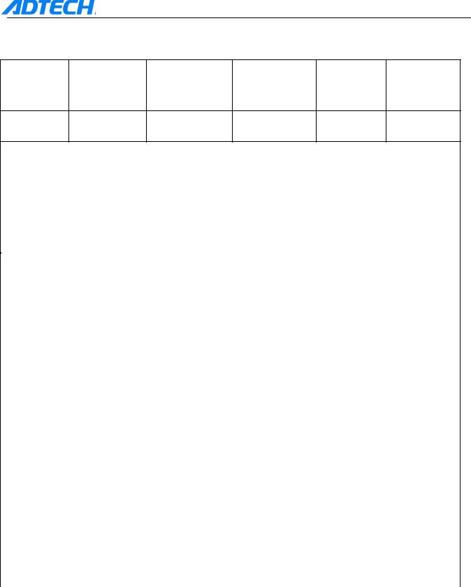
Version Upgrading Instruction
Edit Printer
Program NO |
First update |
Version Number |
Total page |
engineer engineer
XT20080505B |
2012-1-7 |
A1301 |
194 |
Xu Yuwen |
calibration records
Date |
version/page |
result |
confirmation |
|
|
|
|
|
|
|
|
|
|
|
|
|
|
|
|
|
|
|
|
|
|
|
|
|
|
|
|
|
|
|
|
|
|
|
|
|
|
|
|
|
|
|
|
- 2 -

ADT-CNC4840 Milling Controller
Notice
Transportation and storage:
1.The product packing case piles the repeat not to be possible to surpass six 2.Cannot climb up in the product packing case, stand or the laying aside heavy
3.cannot use and the product connected electric cable dragging or the transporting product
4.refuses the collision, to scratch the kneading board and the display monitor
5.product packing case should avoid moist, the insolation as well as the rain
drenches
Opens a box and check :
1.after opening the packing, please confirm whether is the product
2.inspection product which you purchase in the transportation whether to have on the way damages
3.comparison detailed list to confirm various parts are whether complete, whether there is appendix or transportation damage situations and so on to damage
4.like existence product model symbol, not to lack, please promptly relate with Our company
Connection:
1.participates in the wiring and the inspection personnel must be has the corresponding ability specialists
2.product to earth reliably, the earth resistance should be smaller than 4 ohms, cannot use the neutral axis (zero curve) to replace the grounding
3.wiring to be correct, be reliable, in order to avoid causes the product breakdown or the unexpected consequence
4.with the product connection surge absorber diode must according to the stipulation direction connection, otherwise before will damage product
5.to insert pulls out the plug or turns on the product engine case, must shut off the product power source
Overhaul
1.before the overhaul either replaces the primary device, must the dump
2.have when the short circuit or the overload should the trouble shooting, after the trouble shooting, if only then starts
3.not to be possible passes the power failure frequently to the product, after the power failure, to electrify, time interval at least 1 minute
Others
1.without the permission, please arbitrarily do not turn on the cabinet.
2.the long time does not use, please dump.
3.the special attention do not let the dust, the powdered iron enter the controller.
4. outputs the relay, if uses the non-solid state relay, then must in the relay winding the parallel after flow diode. The inspecting office receives a
- 3 -

 ADT-CNC4840 Milling Controller telegram the source whether to meet the requirement, ceases burns out the
controller.
5. controller's life and the ambient temperature have the very big relations, if processes the scene hyperpyrexia, pays respects installs the radiation ventilator. Controller permission work ambient temperature scope in 0 -60between. 6. avoids, in the high temperature, moist, the multi-dust or have in the caustic gas environment to use. 7. in the vibration intense place, should add the rubber crash pad to carry on the cushion.
Maintenance
Under general exploitation conditions (environmental condition: The daily average 30 , the load factor 80%, the service factor daily 12 hours), please press the following project to carry on the daily inspection and the periodic inspection.
|
|
1.confirmation ambient temperature, |
|
|
|
temperature, dust foreign matter |
|
Daily inspection |
Daily |
2. whether there is exceptionally to |
|
vibrate, the sound |
|||
|
|
||
|
|
3. whether air vent and so on blocked by |
|
|
|
the yarn |
|
|
|
|
|
Periodic inspection |
|
1. Firm part whether loose |
|
one year |
2. whether terminal table being damage |
||
|
|||
|
|
|
- 4 -

ADT-CNC4840 Milling Controller
CONTENT
Chapter I Definition of System Interface and Wiring Description................................................................... |
- 7 - |
I.System Structure _________________________________________________________________________- 7 -
1.Parts of CNC4840 NCS __________________________________________________________________- 7 -
2.Notice for Installation____________________________________________________________________- 8 - 3.Installing Dimension ____________________________________________________________________10 -
II.External Connection ____________________________________________________________________11 -
1.External Interface______________________________________________________________________11 -
2.Control Interface of Motor Driver _________________________________________________________13 -
3.Input Interface of Machine_______________________________________________________________14 -
4.Input Expansion Interface _______________________________________________________________18 -
5.Output Interface _______________________________________________________________________20 -
6.Output Expansion Interface ______________________________________________________________22 -
7.Analog Output ________________________________________________________________________24 -
8.Handheld box _________________________________________________________________________25 -
9.Electrical Connection Diagram ___________________________________________________________26 -
10.Legend of connection between CNC4840 and servo/stepper driver ______________________________27 -
Chapter II Programming ............................................................................................................................... |
- 32 - |
1.1Basic knowledge of programming _____________________________________________________32 -
1.1.1Moving direction and definition of control axis _______________________________32 -
1.1.2Coordinate system of machine tool and work piece (G53, G54~G599) _________33 -
1.1.3Mode function and modeless function _________________________________________34 -
1.1.4Feed function ____________________________________________________________________34 -
1.1.5Program structure _________________________________________________________________35 -
1.2Preparatory function (G code) ________________________________________________________37 -
1.2.1List of G codes ___________________________________________________________________37 -
1.2.2Interpolation (G00, G01, G02, G03) __________________________________________________38 -
1.2.3Pause instruction (G04) ____________________________________________________________41 -
1.2.4Plane selection (G17, G18, G19) _____________________________________________________41 -
1.2.5Instructions of Coordinate System (G53~G59, G591~G599, G92) ___________________________41 -
1.2.6Reference point related instructions (G27, G28, G29)_____________________________________44 -
1.2.7Tool compensation (G40, G41, G42, G43, G44, G49) ____________________________________46 -
1.2.8Hole processing cycle (G73~G89) ____________________________________________________75 -
1.3Auxiliary function (M, S, T) __________________________________________________________87 -
1.3.1M code _________________________________________________________________________87 -
1.3.2S code __________________________________________________________________________89 -
1.3.3T code __________________________________________________________________________89 -
1.4Macro ____________________________________________________________________________90 -
1.4.1Variable instruction _______________________________________________________________90 -
1.4.2Macro program call _______________________________________________________________92 -
1.4.3Variable_________________________________________________________________________96 -
1.4.4Calculation instruction ____________________________________________________________100 -
1.4.5Control instruction _______________________________________________________________104 -
1.4.6Notice for using macro ____________________________________________________________107 -
1 |
Chapter III Operation ........................................................................................................................ |
- 108 - |
1.1.1Description of Control Panel _____________________________________________________108 -
2.1.1LCD panel ___________________________________________________________________108 -
1.2.1position display _______________________________________________________________110 -
1.2.2Program display _______________________________________________________________113 -
1.2.3Settings of tool compensation parameters ___________________________________________117 -
1.2.4Setting and modification of system parameters, coordinate parameters, network parameters, setting parameters and parameter management ___________________________________118 -
1.2.5Diagnosis display setting ________________________________________________________123 -
-5 -

ADT-CNC4840 Milling Controller
1.2.6Alarm display_________________________________________________________________128 -
1.3Description of operating mode _______________________________________________________129 -
1.2.1Selection of operating mode ________________________________________________________129 -
1.4Manual operations_________________________________________________________________130 -
1.4.2reset relative position ___________________________________________________________130 -
1.4.3Operations of manual auxiliary functions ____________________________________131 -
1.5Auto operation ____________________________________________________________________132 -
1.5.1start of program _______________________________________________________________132 -
1.5.2stop of auto operation ______________________________________________________132 -
1.5.2There are two ways to stop the auto operation. One is to input stop order in where
it is to stop in advance via the program, and the other way is to use the button on control panel.
- 132 -
1.5.3feed rate adjustment in auto operation ______________________________________133 -
1.2.2In [Auto] mode, in the interface of display position, you can rotate the auto rate
shift to change the manual rate. The range of the rate is 0~150% (with 10% per shift) . The feed rate is specified by F instruction or parameters. _________________________________________133 -
1.5.4Single program segment ________________________________________________________133 -
1.5.5Skip the program segment _______________________________________________________134 -
1.6Zero fill __________________________________________________________________________134 -
1.6.1return to reference point manually_________________________________________________134 -
1.7Single-step/Handwheel operation_____________________________________________________135 -
1.7.1Single-step feed _______________________________________________________________135 -
1.7.2Handwheel feed _______________________________________________________________135 -
1.8Edition operation __________________________________________________________________136 -
1.8.1Preparation before program storage and edition ______________________________________136 -
1.8.2Save the program in storage _____________________________________________________136 -
1.8.3Program searching _____________________________________________________________137 -
1.8.4Adding program_______________________________________________________________138 -
1.8.5Deleting program ______________________________________________________________138 -
1.8.6Deleting all programs __________________________________________________________138 -
1.8.7Inserting, modifying, deleting word _______________________________________________138 -
1.8.8Storage capacity _______________________________________________________________140 -
1.8.9Download of program __________________________________________________________140 -
1.9Recording operation _______________________________________________________________143 -
1.10Composite key ____________________________________________________________________144 -
1.11Parameters ______________________________________________________________________146 -
1.11.1GenralParam (P1.) _____________________________________________________________146 -
1.11.2Network parameter(P2.)_________________________________________________________164 -
1.11.3Axis parameter configuration (P3.) ______________________________________________166 -
1.11.4Tool magazine parameter (P4.) ___________________________________________________179 -
1.11.6IO Configuration parameter(P5.)__________________________________________________180 -
1.11.7Manager Parameter (P6.)________________________________________________________180 -
1.12System alarming __________________________________________________________________186 -
1.12.1NC Program executing alarming__________________________________________________186 -
1.12.2system environment alarming __________________________________________________188 -
1.2Annex1 setting of workpiece coordinate and tool setting _________________________________190 -
1.3Annex 2 Table of operating environment ______________________________________________190 -
1.4Annex3 Description of keyboard _____________________________________________________191 -
-6 -
ADT-CNC4840 Milling Controller
Chapter I Definition of System Interface and Wiring Description
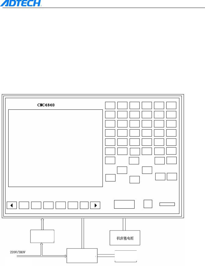
I. System Structure
1. Parts of CNC4840 NCS
CNC4840 NCS is composed by the following main units: 1. CNC control unit (Control device CNC4840)
2. Stepper motor driver (Digital AC servo driver)
3. Stepper motor (Servo motor)
4. Electric cabinet
+24V switching |
|
Electric cabinet |
|
power supply |
|
|
|
|
|
|
|
|
Stepper driver or digital |
Stepper motor |
or servo |
AC power supply input |
AC servo motor driver |
motor |
|
- 7 -
|
|
ADT-CNC4840 Milling Controller |
|
|
|
2. Notice for Installation |
||
|
Conditions for mounting electric cabinet |
|
The electric cabinet should be able to prevent the entry of dust, cooling liquid and organic solution |
||
effectively.
The electric cabinet should be designed in a way that the distance between rear cover and the casing should not be less than 20CM. Considering the temperature rise inside the electric cabinet, the
difference in temperature between inside and outside should not exceed 10°C.
Fan should be installed inside the electric cabinet so as to ensure the good air circulation inside.
Display panel should be installed in a place away from the cooling liquid.
Try to reduce the external electric interference to prevent it from transmitting to the system.
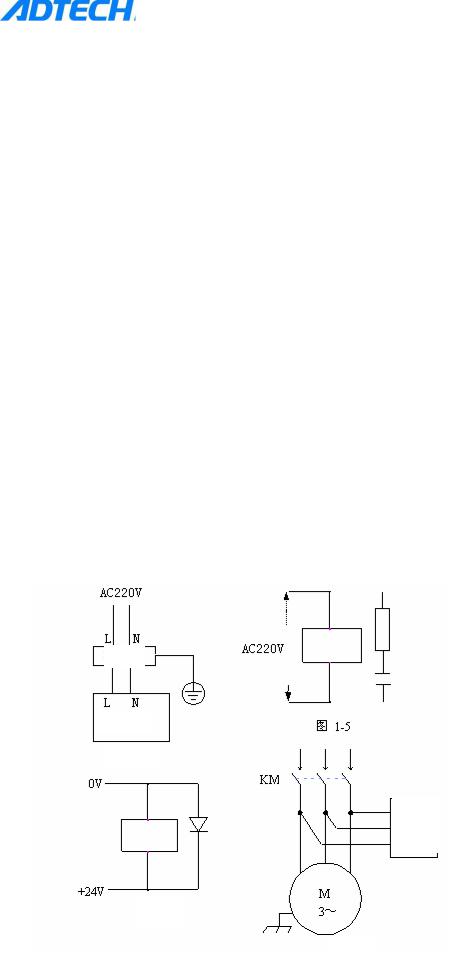
Methods to prevent the interference
When designing the system, several anti-interference measures such as shielding space electromagnetic radiation, absorbing impulse current, and filtering power supply noise are adopted, which to a certain extent prevents the external interference source from affecting the system. To ensure the stable operation of the system, the following measures should be done when installing:
1:CNC should be away from the devices that generate the interference (such as transducer, AC contactor, electrostriction generator, high pressure producer, and segment separator of dynamic line). At the same time, the switching power supply should be connected with individual filter to enhance the anti-interference capability of CNC. (As picture 1-4)
2:The system should be powered by isolating transformer, and the machine tool on which the system is installed should be grounded. CNC and driver should connect the individual earth line from the ground point.
3:Interference suppression: Connect a RC return circuit (0.01μF, 100~200Ω, as picture 1-5) in
parallel at the two ends of AC coil. The RC returning circuit should be as close to the inductive load as possible when installing. Connect a freewheeling diode in parallel reversely at the two ends of DC coil (as picture 1-6). Connect surge absorbers in parallel at the winding ends of AC motor (as picture 1-7).
Filter
Switching power supply
Picture 1-4
Surge absorber
Picture 1-6
Picture 1-7
- 8 -
ADT-CNC4840 Milling Controller
4: To reduce the interface between the CNC signal cables and the electric cables, the wiring should follow the rules below:
Group |
Type of Cable |
Wiring Requirements |
|
|
|
|
|
|
AC supply line |
Bind the cable of group A and group B and C separately, |
|
|
|
||
|
|
||
A |
AC coil |
reserve the distance of at least 10cm, or electromagnetic |
|
|
|
shielding the group A cable |
|
|
AC contactor |
||
|
|
||
|
|
|
|
|
DC coil (24VDC) |
|
|
|
|
|
|
|
DC relay (24VDC) |
Bind the cable of group B and group A separately, or shield |
|
B |
|
||
|
|||
Cable connecting system and electric cabinet |
the cable of group B. Cables of group B and group C should |
||
|
|
be placed as far as better. |
|
|
Cable connecting system and controller |
||
|
|
||
|
|
|
|
|
Cable connecting system and servo driver |
|
|
|
|
Bind the cable of group C and group A separately, or shield |
|
|
Position feedback cable |
||
C |
the cable of group C. The distance between group C and |
||
|
|||
Position coder cable |
group B should be at least 10cm, and the cable uses the |
||
|
|||
|
twisted pair. |
||
|
|
||
|
Handwheel cable |
|
|
|
|
|
|
|
Other cables for the purpose of shielding |
|
|
|
|
|
- 9 -
ADT-CNC4840 Milling Controller
3.Installing Dimension
Installing dimension of CNC4840 controller
- 10 -
ADT-CNC4840 Milling Controller
II. External Connection
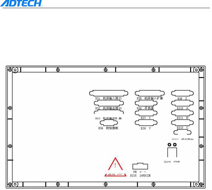
1. External Interface
CNC4840 control unit is connected to the external devices via the rear and front interfaces.
1. The outer casing of CNC4840 is defined as follows:
XS1 |
|
|
|
|
|
|
|
input interface |
XS5 expansion input |
||||||
XS2 |
|
|
|
|
|
||
output interface |
XS6 handheld box |
||||||
XS3 |
expansion output |
|
|
|
|
|
|
XS4 |
|
|
|
|
|
|
|
additional panel |
|
|
|
|
|
||
|
|
XS13 analog |
|
||||
|
|
|
|
|
|||
|
|
|
|
output |
|||
XS14 network
DC 24V
X, Y, Z, A, B, and C refer to the connecting signal of stepper motor driver or digital AC servo driver of each axis. CNC4840 controller uses X, Y, Z, A, B, and C axes at the moment.
Input interfaces and expansion input interfaces of the machine are limit and digital input signals of each axis. Output interfaces and expansion output interfaces are the digital output signal.
CNC4840 controller uses the 24V DC power supply, and the internal power consumption is about 5W.
- 11 -
ADT-CNC4840 Milling Controller
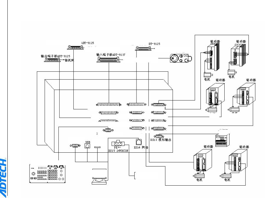
General Wiring Diagram
Output terminal board
|
|
|
Connect to machine tool |
|||
|
|
|
|
|
|
|
|
|
|
Input terminal board |
|||
Output terminal board |
||||||
|
|
|
|
|
||
|
|
|
|
|
||
|
|
|
|
|
|
|
|
|
Connect to machine tool |
|
|||
|
|
|
|
|
|
|
XS2 Output interface of machine
XS3 Output expansion of machine
XS4 Additional panel
Serial port
USB disk
Additional panel
Computer
Input terminal board
Connect to machine tool
Connect to machine tool
XS6 Handheld box |
XS10 A axis |
||
XS7 X axis |
XS11 B axis |
||
XS8 Y axis |
XS12 C axis |
||
|
|
|
XS13 Analog output |
|
|
|
|
|
|
|
|
|
|
|
|
|
XS14 |
|
|
|
network |
|
|
24V DC power supply
Driver |
|
|
|
Driver |
|
|
|
|
|
|
|
|
Motor |
|
|
|
|
Driver |
|
|||
Motor |
|
Driver |
||||
|
|
|
|
|||
|
|
|
||||
|
|
|
|
|
|
|
- 12 -
Motor Motor
Motor
Driver |
|
|
|
Driver |
|
|
|
|
Motor |
|
Motor |
|
|
|
ADT-CNC4840 Milling Controller
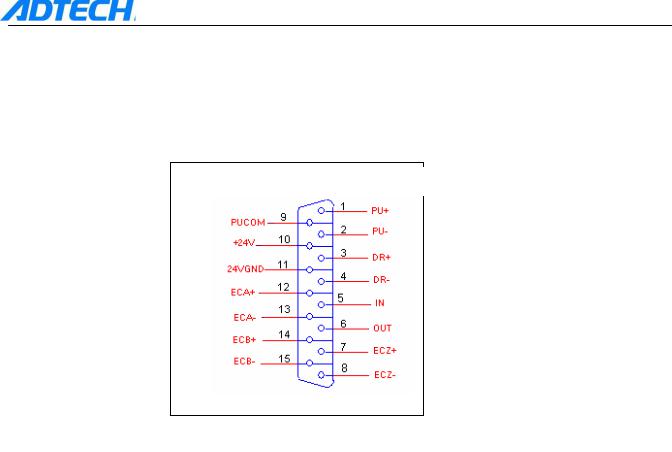
2. Control Interface of Motor Driver
There are 8 interfaces for the driver (X, Y, Z, A, B, C axes), and the interface definition is the same. Refer to the following picture:
Pulse interface of axis 1-6
Pulse Interface of X/Y/Z/A/B/C Axis
Line S/N |
Name |
Function |
|
1 |
nPU+ |
Pulse signal + |
|
2 |
nPU- |
Pulse signal - |
|
3 |
nDR+ |
Direction signal + |
|
4 |
nDR- |
Direction signal - |
|
5 |
IN |
General input, can be used as alarm input (X-66 |
|
Y-67 Z-68 A-69 B-70 C-71) |
|||
|
|
||
|
|
|
|
6 |
OUT |
General output (X-48 Y-49 Z-50 A-51 B-52 C-53) |
|
|
|
|
|
7 |
nECZ+ |
Coder Z-phase input + (X-72 Y-73 Z-74 A-75 |
|
B-76 C-77) |
|||
|
|
||
|
|
|
|
8 |
nECZ- |
Coder Z-phase input - |
|
9 |
PUCOM |
Used for driver with single-end input |
|
10 |
+24V |
Provide internal 24V power supply, directly connected |
|
|
|
||
11 |
24VGND |
with 24V power supply of controller |
|
|
|||
|
|
|
|
12 |
nECA+ |
Coder A-phase input + (X-78 Y-80 Z-82 A-84 |
|
B-86 C-88) |
|||
|
|
||
|
|
|
|
13 |
nECA- |
Coder A-phase input - |
|
14 |
nECB+ |
Coder B-phase input + (X-79 Y-81 Z-83 A-85 |
|
B-87 C-89) |
|||
|
|
||
|
|
|
|
15 |
nECB- |
Coder B-phase input - |
|
|
|
|
- 13 -
ADT-CNC4840 Milling Controller
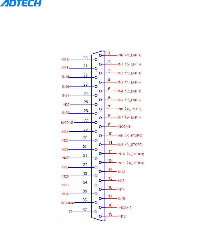
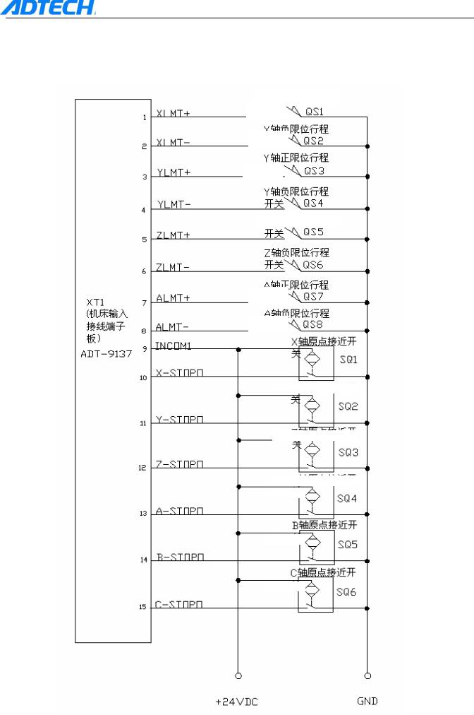
3. Input Interface of Machine
1) The digital input interfaces include the zero points of XYZABC axes, hardware limit signal of XYZA axes, etc. The definition is as follows:
- 14 -

ADT-CNC4840 Milling Controller
Input Interface of Machine
Line S/N |
Name |
Function |
|
|
|
|
|
1 |
IN0 (X_LMT+) |
X positive limit |
|
|
|
|
|
2 |
IN1 (X_LMT-) |
X negative limit |
|
|
|
|
|
3 |
IN2 (Y_LMT+) |
Y positive limit |
|
|
|
|
|
4 |
IN3 (Y_LMT-) |
Y negative limit |
|
|
|
|
|
5 |
IN4 (Z_LMT+) |
Z positive limit |
|
|
|
|
|
6 |
IN5 (Z_LMT-) |
Z negative limit |
|
|
|
|
|
7 |
IN6 (A_LMT+) |
A positive limit |
|
|
|
|
|
8 |
IN7 (A_LMT-) |
A negative limit |
|
|
|
|
|
9 |
INCOM1 |
Common input terminal (24v+, 12v+) |
|
|
|
|
|
10 |
IN8 (X_STOP0) |
X axis zero |
|
|
|
|
|
11 |
IN9 (Y_STOP0) |
Y axis zero |
|
|
|
|
|
12 |
IN10 (Z_STOP0) |
Z axis zero |
|
|
|
|
|
13 |
IN11 (A_STOP0) |
A axis zero |
|
|
|
|
|
14 |
IN12 (B_STOP0) |
B axis zero |
|
|
|
|
|
15 |
IN13 (C_STOP0) |
C axis zero |
|
|
|
|
|
16 |
IN14 |
Air pressure alarm input |
|
|
|
|
|
17 |
IN15 |
Spare input (used to detect the material-champing |
|
alarm input signal during the operation) |
|||
|
|
||
18 |
INCOM2 |
Common input terminal (24v+, 12v+) |
|
|
|
|
|
19 |
IN16 |
B positive limit |
|
|
|
|
|
20 |
IN17 |
B negative limit |
|
|
|
|
|
21 |
IN18 |
C positive limit |
|
|
|
|
|
22 |
IN19 |
C negative limit |
|
|
|
|
|
23 |
IN20 |
Cycle ON |
|
|
|
|
|
24 |
IN21 |
Pause |
|
|
|
|
|
25 |
IN22 |
Emergency stop |
|
|
|
|
|
26 |
IN23 |
Alarm input of main axis |
|
|
|
|
|
27 |
INCOM3 |
Common input terminal (24v+, 12v+) |
|
|
|
|
|
28 |
IN24 |
Input for triggering feeler device |
|
|
|
|
|
29 |
IN25 |
Input for protecting feeler device |
|
|
|
|
|
30 |
IN26 |
Spare input |
|
|
|
|
|
31 |
IN27 |
Spare input |
|
|
|
|
|
32 |
IN28 |
Spare input |
|
|
|
|
|
33 |
IN29 |
Spare input |
|
|
|
|
|
34 |
IN30 |
Spare input |
|
|
|
|
|
35 |
IN31 |
Spare input |
|
|
|
|
|
36 |
INCOM4 |
Common input terminal (24v+, 12v+) |
|
|
|
|
|
37 |
|
|
|
|
|
|
- 15 -
ADT-CNC4840 Milling Controller
2) Diagram of wiring between input interfaces and photoelectric switch/proximity switch is as follows:
|
X positive |
limit Go Switch |
|
|||||||||||||
|
|
|
|
|
|
|
|
|
|
|
|
|
|
|
|
|
|
|
|
|
|
|
|
|
|
|
|
|
|
|
|
|
|
|
X negative limit Go Switch |
|
||||||||||||||
|
|
|
|
|
|
|
|
|
|
|
|
|
|
|
|
|
|
|
|
|
|
|
|
|
|
|
|
|
|
|
|
|
|
|
Y positive |
|
limit |
Go Switch |
|
|
||||||||||
|
|
|
|
|
|
|
|
|
|
|
||||||
|
|
|
|
|
|
|
|
|
|
|
|
|
|
|
||
|
|
|
|
|
|
|
|
|
|
|
|
|
|
|
|
|
|
|
|
|
|
|
|
|
|
Go Switch |
|
||||||
|
Y negative |
limit |
|
|||||||||||||
|
|
|
|
|
|
|
|
|
|
|
|
|
|
|
|
|
|
|
|
|
|
|
|
|
|
|
|
|
|
|
|
|
|
|
Z positive |
|
|
|
|
|
|
|
|
|
|
|
||||
|
limit Go Switch |
|
||||||||||||||
|
|
|
|
|
|
|
|
|
|
|
|
|
|
|
|
|
|
|
|
|
|
|
|
|
|
|
|
|
|
|
|
|
|
XT1 |
|
|
|
|
|
|
|
|
|
|
|
|
|
|
|
|
|
|
|
|
|
|
|
|
|
|
|
|
|
|
|
|
|
Z negative |
limit Go Switch |
|
||||||||||||||
(Input |
|
|||||||||||||||
terminal |
|
|
|
|
|
|
|
|
|
|
|
|
|
|
|
|
block of |
A positive |
|
|
|
|
|
|
|
|
|
|
|
||||
|
|
|
|
|
|
|
|
|
|
|
||||||
machine |
|
|
|
|
|
|
|
|
|
|
|
|||||
limit Go Switch |
|
|||||||||||||||
tool) |
|
|
|
|
|
|
|
|
|
|
|
|
|
|
|
|
X origin |
proximity switch |
|
||||||||||||||
|
|
|||||||||||||||
|
|
|||||||||||||||
|
|
|
|
|
|
|||||||||||
|
|
|
|
|
|
|
|
|||||||||
|
Y origin |
|
proximity |
switch |
|
|||||||||||
|
|
|
|
|||||||||||||
|
|
|
|
|
||||||||||||
|
Z origin |
|
proximity |
switch |
|
|||||||||||
|
|
|
|
|||||||||||||
|
|
|
|
|
||||||||||||
|
A origin |
|
proximity |
switch |
|
|||||||||||
|
|
|
||||||||||||||
|
B origin |
|
|
|
||||||||||||
|
|
proximity |
switch |
|
||||||||||||
|
|
|
||||||||||||||
|
C origin |
|
|
|
||||||||||||
|
|
proximity |
switch |
|
||||||||||||
- 16 -
ADT-CNC4840 Milling Controller
XT1 (Input terminal block of machine tool)
Spare input
Spare input
Spare input
Spare input
Spare input
Spare input
Cycle ON
Pause
Emergency stop Spindle alarm input Spare input
Spare input
Spare input
Spare input
Spare input
Spare input
Spare input
Spare input
- 17 -
ADT-CNC4840 Milling Controller
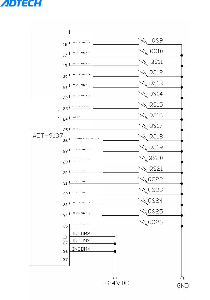
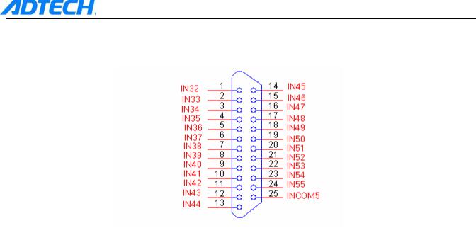
4.Input Expansion Interface
1)Digital input interfaces include BC hardware limit, other spare input signals, etc. the definitions are as follows:
|
|
Input Expansion Interface |
|
|
|
|
|
Line S/N |
Name |
|
Function |
|
|
|
|
1 |
IN32 |
|
Spare input |
2 |
IN33 |
|
Spare input |
3 |
IN34 |
|
Spare input |
4 |
IN35 |
|
Spare input |
5 |
IN36 |
|
Spare input |
6 |
IN37 |
|
Spare input |
7 |
IN38 |
|
Spare input |
8 |
IN39 |
|
Spare input |
9 |
IN40 |
|
Spare input |
10 |
IN41 |
|
Spare input |
11 |
IN42 |
|
Spare input |
12 |
IN43 |
|
Spare input |
13 |
IN44 |
|
Spare input |
14 |
IN45 |
|
Spare input |
15 |
IN46 |
|
Spare input |
16 |
IN47 |
|
Spare input |
17 |
IN48 |
|
Spare input |
18 |
IN49 |
|
Spare input |
19 |
IN50 |
|
Spare input |
20 |
IN51 |
|
Spare input |
21 |
IN52 |
|
Spare input |
22 |
IN53 |
|
Spare input |
23 |
IN54 |
|
Spare input |
24 |
IN55 |
|
Spare input |
25 |
INCOM5 |
|
Common input terminal (24v+, 12v+) |
- 18 -
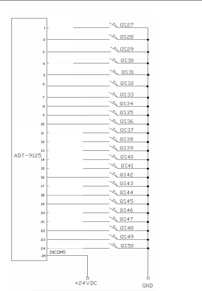
 ADT-CNC4840 Milling Controller 2) The wiring of expansion input interface and proximity switch is shown as follows:
XT2 (Input terminal block of machine tool)
Spare input Spare input Spare input Spare input Spare input Spare input Spare input Spare input
Spare input Spare input
Spare input Spare input Spare input
Spare input Spare input Spare input Spare input Spare input Spare input Spare input Spare input
Spare input Spare input Spare input
- 19 -
ADT-CNC4840 Milling Controller
5.Output Interface
1)The output interface and the wiring are defined as follows:
|
Output Interfaces |
|
|
|
|
Line S/N |
Name |
Function |
|
|
|
1 |
OUT0 |
Spindle clockwise rotation (M03) |
2 |
OUT1 |
Spindle anti -clockwise rotation |
3 |
OUT2 |
Illumination (M66, M67) |
4 |
OUT3 |
Cooler 1 (M08, M09) |
5 |
OUT4 |
Cooler 2 (M68, M69) |
6 |
OUT5 |
Lubrication (M32, M33) |
7 |
OUT6 |
Adjusting tool (M10, M11) |
8 |
OUT7 |
Tool change (M12, M13) |
9 |
OUT8 |
Chamber air blowing (M14, M15) |
10 |
OUT9 |
Clamp materials (M16, M17) |
11 |
OUT10 |
Feeding (M18, M19) |
12 |
OUT11 |
Start light (M40, M41) |
13 |
OUT12 |
Stop light (M42, M43) |
14 |
OUT13 |
Warning light (M44, M45) |
15 |
OUT14 |
Dumping (M46, M47) |
16 |
OUT15 |
Discharging scraps (M48, M49) |
17 |
OUT16 |
Knife warehouse + (M50, M51) |
18 |
OUT17 |
Knife warehouse - (M52, M53) |
19 |
OUT18 |
Spare output (M54, M55) |
20 |
OUT19 |
Spare output (M56, M57) |
21 |
OUT20 |
Spindle gear shift control 1 (M58, |
22 |
OUT21 |
Spindle gear shift control 2 (M60, |
23 |
OUT22 |
Spindle gear shift control 3 (M62, |
24 |
OUT23 |
Spindle gear shift control 4 (M64, |
25 |
OUT_GND1 |
Common power supply of 12v-, 24v- |
- 20 -

2) Wiring diagram of output interface is as follows:
Spindle clockwise rotation
Spindle anti-clockwise rotation
Illumination
Cooler 1
Cooler 2
Lubrication
Adjusting tool
Tool change
Chamber air blowing
Clamp materials
Feeding
Start light
Stop light
Warning light
Spare output
Spare output
Spindle gear shift control 1
Spindle gear shift control 2
Spindle gear shift control 3
Spindle gear shift control 4
Spindle clockwise rotation
Spindle anti-clockwise rotation
Illumination
ADT-CNC4840 Milling Controller
tool) machine of block terminal expansion (Output XT3
- 21 -
ADT-CNC4840 Milling Controller
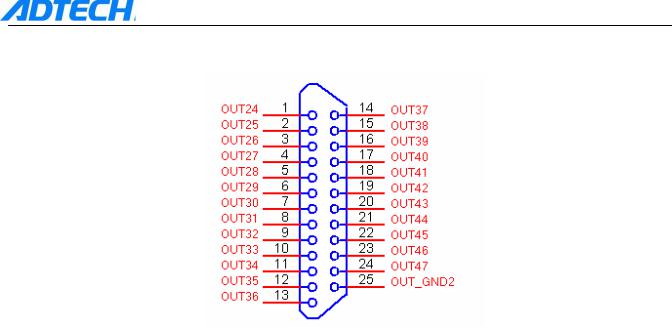
6.Output Expansion Interface
1)The expansion output interface and the wiring are defined as follows:
|
Output Expansion Interface |
|
|
|
|
Line S/N |
Name |
Function |
|
|
|
1 |
OUT24 |
Spare output (M110, M111)F10 |
2 |
OUT25 |
Spare output (M112, M113)F11 |
3 |
OUT26 |
Spare output (M114, M115)F12 |
4 |
OUT27 |
Spare output (M116, M117)F13 |
5 |
OUT28 |
Spare output (M118, M119)F14 |
6 |
OUT29 |
Spare output (M120, M121)F15 |
7 |
OUT30 |
Spare output (M122, M123)F16 |
8 |
OUT31 |
Spare output (M124, M125)F17 |
9 |
OUT32 |
Spare output (M126, M127)F18 |
10 |
OUT33 |
Spare output (M128, M129)F19 |
11 |
OUT34 |
Spare output (M130, M131)F20 |
12 |
OUT35 |
Spare output (M132, M133) |
13 |
OUT36 |
Spare output (M134, M135) |
14 |
OUT37 |
Spare output (M136, M137) |
15 |
OUT38 |
Spare output (M138, M139) |
16 |
OUT39 |
Spare output (M140, M141) |
17 |
OUT40 |
Spare output (M142, M143) |
18 |
OUT41 |
Spare output (M144, M145) |
19 |
OUT42 |
Spare output (M146, M147) |
20 |
OUT43 |
Spare output (M148, M149) |
21 |
OUT44 |
Spare output (M150, M151) |
22 |
OUT45 |
Spare output (M152, M153) |
23 |
OUT46 |
Spare output (M154, M155) |
24 |
OUT47 |
Spare output (M156, M157) |
25 |
OUT_GND2 |
Common power supply of 12v-, 24v- |
- 22 -
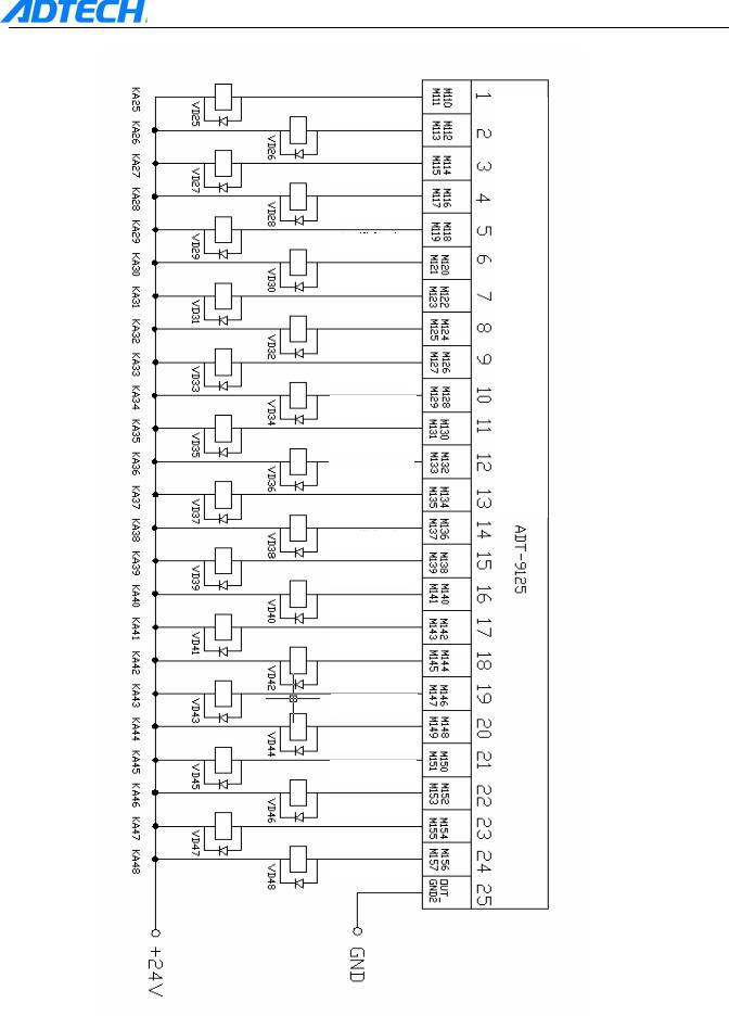
2) Wiring diagram of expansion output interface is as follows:
Spare output
Spare output
Spare output
Spare output
Spare output
Spare output
Spare output
Spare output
Spare output
Spare output
Spare output
Spare output
Spare output
Spare output
Spare output
Spare output
Spare output
Spare output
Spare output
Spare output
Spare output
Spare output
Spare output
Spare output
ADT-CNC4840 Milling Controller
tool) machine of block terminal expansion Output( XT4
- 23 -
ADT-CNC4840 Milling Controller
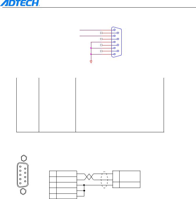
7.Analog Output
1)The analog output interface is defined as follows:
|
P2 |
DAOUT1 |
1 |
DAOUT2 |
6 |
2 |
|
|
7 |
|
3 |
|
8 |
|
4 |
|
9 |
|
5 |
|
|
24VGND |
|
|
Analog Output |
|
|
|
Line S/N |
Name |
Function |
1 |
DAOUT1 |
Analog voltage output (0V—12V+) |
|
|
|
2 |
DAOUT2 |
Analog voltage output (0V—12V+) |
|
|
|
3 |
|
|
|
24V- |
Provide internal24V grounding |
4 |
||
|
|
|
5 |
|
|
2) Wiring diagram of analog output is as follows:
efinition of analog utput interface
1
6
9
5
XS13 interface
Connection of CNC4840
transducer
CNC4840 (analog output) |
CWF-S1 transducer |
|
XS13 interface |
signal interface |
|
1 |
DAOUT1 |
|
|
|
|
|
|
VI1 |
2 |
DAOUT2 |
|
3 |
24V- |
CM |
|
||
4 24V-
Note: Choose either DAOUT1 5 24V- or DAOUT2 to connect the
transducer
- 24 -
ADT-CNC4840 Milling Controller
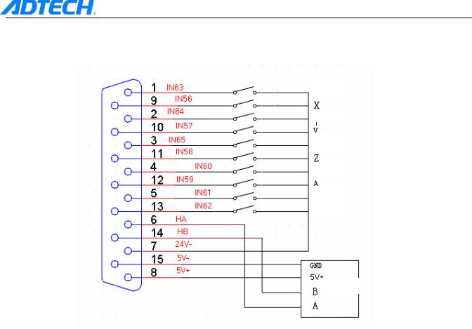
8. Handheld box
Handheld box: Connected with our standard handheld box ADT-CNC4A, multiplexing with manual pulse generator count and Y-axis coder
High
Medium
Low
Start
Stop
Emergency stop
Coder
Definition of corresponding casing: Handheld box
Line S/N |
Name |
|
Function |
|
|
|
|
1 |
IN63 |
|
0.1 shift switch -High |
2 |
IN64 |
|
0.01 shift switch -Medium |
3 |
|
IN65 |
0.001 shift switch -Low |
4 |
IN60 |
|
Start-up |
5 |
IN61 |
|
Stop |
6 |
HA |
|
Handle coder phase-A input signal |
7 |
24V- |
|
Internal -24V power supply |
8 |
5V+ |
|
Internal +5V power supply |
9 |
IN56 |
|
Select X axis |
10 |
IN57 |
|
Select Y axis |
11 |
IN58 |
|
Select Z axis |
12 |
IN59 |
|
Select A axis |
13 |
IN62 |
|
emergency stop |
14 |
HB |
|
Handle coder phase-B input signal |
15 |
5V- |
|
Internal -5V power supply |
- 25 -
ADT-CNC4840 Milling Controller
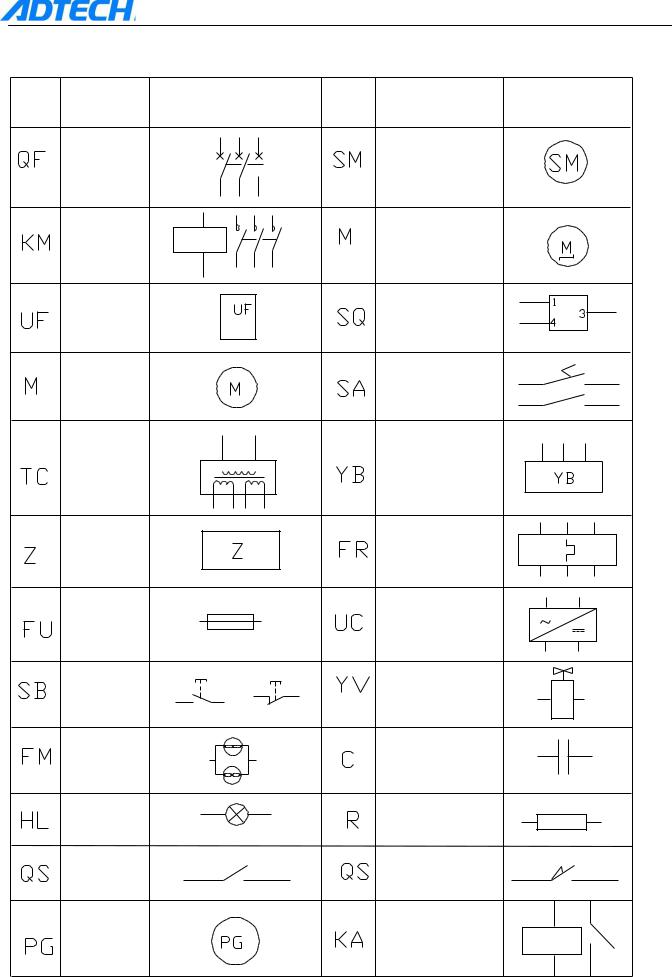
9. Electrical Connection Diagram
Sign Name |
Chart |
Sign |
Name |
Chart |
Breaker |
|
|
Servomotor |
|
Contactor |
|
|
Steppermotor |
|
Transducer |
|
|
Proximityswitch |
|
Motor |
|
|
Footswitch |
|
Transformer |
|
|
Thermalrelay |
|
filter |
|
|
thermalrelay |
|
Fuse |
|
|
Switchingpowersupply |
|
Button |
|
|
Solenoidvalve |
|
Airblower |
|
|
compacitor |
|
indicator |
|
|
resistor |
|
Touchswitch |
|
|
Goswitch |
|
Coder |
|
|
Relay |
|
- 26 -
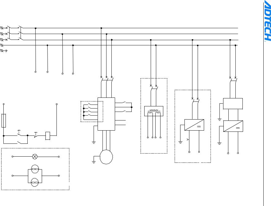
- 27 -
QF1 |
KM1 |
L11 |
L12 |
L1 |
|
L21 |
L22 |
L2 |
|
L31 |
L32 |
L3 |
|
N
PE
|
L12 |
N1 |
|
|
|
|
|
|
|
|
|
|
For power supply |
L22 |
N2 |
|
|
|
|
|
|
|
|
|
Use 220V power supply when |
|
|
|
QF2 |
|
|
|
|||
|
of servo driver |
using 220V solenoid valve |
|
|
|
|
|
|
|
||
|
|
|
|
|
|
|
|
|
QF3 |
||
L11 |
|
|
|
|
R |
S |
T |
|
KA1 |
|
|
|
|
|
N |
|
|
Transducer |
|
M03 |
|
|
|
|
|
|
|
KA21 |
|
|
FWD |
|
|
|
|
|
|
|
|
X1 |
|
|
|
|
|
|
TC |
|
|
|
|
|
|
|
|
|
|
|
|
|
|
|
|
|
|
|
|
COM |
|
|
|
|
|
|
|
KA22 |
|
|
CM |
|
|
|
|
|
|
|
|
X2 |
|
|
|
|
KA2 |
|
|
|
|
|
|
KA23 |
|
|
|
M04 |
|
|
|
|
|
|
|
X3 |
|
|
REV |
|
|
|
|
|
|
|
|
KA24 |
|
|
|
|
|
|
|
|
|
|
|
X4 |
|
|
|
|
|
|
|
|
|
|
|
COM |
|
|
|
|
|
|
|
|
|
|
|
CM |
|
|
|
DAOUT1 |
|
|
|
FU1 |
|
|
|
|
|
UF |
|
|
Connect |
|
|
|
|
|
|
|
|
|
VI1 |
|
|
|
|
SB1(Green) |
|
|
|
Multi-segment |
|
|
|
24V- |
to XS13 |
60V |
15V |
SB2(Red) |
|
|
control main |
U |
V |
W |
|
||||
|
|
|
|
|
|
|
GND |
|
|
|
|
L13 |
|
KM1 |
N3 |
axis |
|
|
|
|
|
|
|
|
01 |
|
|
|
|
|
|
|
|
|
|
|
02 |
|
|
|
|
|
|
|
|
|
|
|
|
|
|
PE |
|
|
|
|
|
|
|
|
|
|
|
U |
V |
W |
|
|
|
|
|
|
KM1 |
|
|
AC1 |
|
|
|
|
|
|
|
AC1 |
AC2 |
AC2 |
|
|
|
Power |
|
For stepper driver |
|||
|
HL1 |
indication |
M |
|
|
|
|
L13 |
|
|
PE |
|
|
|
|
|
N3 |
|
Use stepper |
||||
|
|
|
3 |
||||
|
|
|
~ |
|
|
|
|
|
|
FM1 |
|
transformer when |
|||
|
|
|
Frequency-changing |
using stepper motor |
|||
L13 |
|
N3 |
main axis |
|
|
|
|
Air blower
FM2
(Optional)
QF5
|
QF4 |
Z |
|
|
|
Filter |
|
|
|
PE |
|
~ |
UC1 |
|
|
|
~ |
UC2 |
|
|
|
||
|
|
|
|
PE |
|
|
|
|
|
PE |
|
+24 |
GND1 |
+24V |
GND |
DC+ |
GND1 |
+24V |
GND |
Use 24V switching |
For CNC4840 |
||
power when using |
controller |
||
24V solenoid valve
driver servo/stepper and CNC4840 between connection of Legend .10
Controller Milling CNC4840-ADT
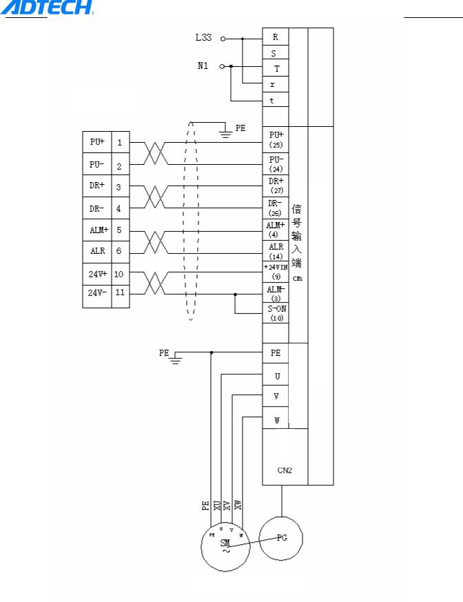
XS7 interface
ADT-CNC4840 Milling Controller
supply power of Input
signal of Input |
Motor Servo axis-X |
|
|
|
Driver |
driver of Output
Driver
X-axis Servo
motor Coder
Example 1: Connection with JaBao QS5 driver
- 28 -
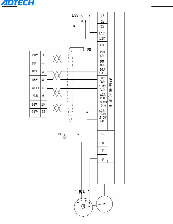
XS7 interface
ADT-CNC4840 Milling Controller
supply power of Input
signal of Input |
|
Motor Servo axis-X |
|
|
|
|
|
Driver |
driver of Output
Driver
X-axis Servo
motor Coder
Example 2: Connection with SGDM driver
- 29 -
 Loading...