

Page 1

A
A
D
D
T--
T
Flame/Plasma Controller
H
H
C
C
6
6
5
5
0
0
0
0
User Manual
(Software)
ADTECH (SHENZHEN) CNC TECHNOLOGY CO., LTD
5th Floor, 27-29th Building, Tianxia IC Industrial Park, Yiyuan road, Nanshan District, Shenzhen Post
code: 518052
Tel: 0755-26722719 (20 lines) Fax: 0755-26722718
E-mail:[email protected] http://www.adtechcn.com
PDF 文件使用 "pdfFactory Pro" 试用版本创建 www.fineprint.com.cn
Page 2

ADT-HC6500 Flame/Plasma/Fluid Controller
Copyright Statement
All property rights of this user manual are reserved by Adtech (Shenzhen) CNC Technology Co., Ltd (ADTECH
for short). No institution or person is allowed to counterfeit, copy, transcribe or translate this user manual without the
permission of ADTECH. This user manual does not include warranty, standpoint expression, or other hints in any form.
ADTECH does not bear any responsibility for any data outflow, benefit loss or business termination due to the product
info contained or mentioned by this user manual. All products and data mentioned are for reference only. Contents are
subject to change without prior notice.
Remark:
1. This user manual is strictly emended and checked by ADTECH (SHENZHEN) CNC TECHNOLOGY CO., LTD,
however, it is not guaranteed that the user manual has no any mistake or error.
2. ADTECH (SHENZHEN) CNC TECHNOLOGY CO., LTD commits itself to improving the product functions
and the service quality consistently. Therefore, the company reserves the right of changing any products as
described, any software program, and the content of the user manual, without prior notice.
All Rights Reserved
ADTECH (SHENZHEN) CNC TECHNOLOGY CO., LTD
1
PDF 文件使用 "pdfFactory Pro" 试用版本创建 www.fineprint.com.cn
Page 3

ADT-HC6500 Flame/Plasma/Fluid Controller
Upgrade Information
Item No. Version No. Revision Date Remark
XT20090305 3.0 2010-1-11 Edition 3
Note: Meanings of the three numbers in version number are as follows:
Library main version No.
Library secondary version No. Reserved
Remark:
This user manual is strictly emended and checked by ADTECH (SHENZHEN) CNC TECHNOLOGY CO., LTD,
however, it is not guaranteed that the user manual has no any mistake or error.
ADTECH (SHENZHEN) CNC TECHNOLOGY CO., LTD commits itself to improving the product functions and the
service quality consistently. Therefore, the company reserves the right of changing any products as described, any
software program, and the content of the user manual, without prior notice.
2
PDF 文件使用 "pdfFactory Pro" 试用版本创建 ÿ www.fineprint.com.cn
Page 4

Safety Notice
Read this safety notice before operating.
I. Notice
1. Notice on safety:
n Original copy of safety notice should be dispensed to every operator.
n Do not open the controller cover without permission; otherwise, it would be out of the range of
guarantee.
n Cut off the power supply in case the machine is not used for a long time.
n Pay attention not to drop any dust or iron powder into the controller.
n Do not pour any liquid into the controller.
n Handle with care, and do not cause any damage.
n Abide by the accident prevention provision and regulations.
ADT-HC6500 Flame/Plasma/Fluid Controller
n Abide by the accident prevention provision and regulations on Oxygen cutting.
n Wear the mask when performing the plasma arc cutting, for the plasma arc will generate UV-b radiation.
2. Notice on correct application:
n Our control system is capable of anti-interfering, but it is still required that your plasma power supply
have shielding function and the plasma controller have good grounding. Otherwise, it will bring serious
result.
n Please set all parameters of the controller strictly according to the user manual; otherwise, it may lead to
failure of control system or even cause serious consequences.
n The controller uses the 24V DC power supply. To avoid short circuit, please pay attention to the voltage,
negative or positive electrode of power supply when installing.
n Good grounding measures are required if the controller is used combining with plasma cutting machine.
n Do not insert or pull out any output plug of controller while the power supply is connected; otherwise, it
will damage the inside of controller.
n If the output relay is non-solid-state relay, a freewheeling diode should be connected in parallel on relay
coil. Check the applied power supply to see whether it is up to requirements, avoid burning out the
controller.
n Controller lifetime has a great relationship with ambient temperature. Install a cooling fan if the
temperature in processing area is too high. The allowable ambient temperature of the controller is
between 0°C and 60°C.
n Do some protection measures if the machine is used in high temperature, damp, or dusty environment,
or environment with corrosive gas.
n In place with strong vibration, add a rubber anti-vibration pad to weaken the vibration.
3
PDF 文件使用 "pdfFactory Pro" 试用版本创建 www.fineprint.com.cn
Page 5

ADT-HC6500 Flame/Plasma/Fluid Controller
II. Statement:
We offer one year factory warranty or lifetime maintenance for any malfunction arising under the normal use. In case of
man-made damage or if the warranty expired, ADTECH will charge a certain cost price of parts. However, the warranty
is not applied to the following conditions:
n The label of serial number is torn down.
n Any damage caused by personal factors
n Any damage caused by natural disasters
n Disassembly, modification, or repair without permission
III. Maintenance:
1. Notice for maintenance and inspection:
n Cut off the power supply of major loop before maintaining or repairing the controller.
n To prevent the accident, the operator should confirm the power supply is cut off.
2. Inspection item and period:
Under the general operating conditions (Daily average 30°C, load rate 80%, operating ratio 12 hours per day), carry out
the following inspections to do the route and periodical inspections.
● Check whether the ambient temperature, dust and foreign
Route inspection Daily
matters exceed the criteria
● Check whether there is abnormal vibration or sound
Half a
● Check whether the firm parts are loosened
Periodical inspection
year
● Check whether the terminal board is damaged
4
PDF 文件使用 "pdfFactory Pro" 试用版本创建 www.fineprint.com.cn
Page 6

ADT-HC6500 Flame/Plasma/Fluid Controller
Content
Chapter I. General................................................................................................................7
Ø Function introduction..........................................................................................................................................7
Ø System Functions................................................................................................................................................7
Ø Application environment....................................................................................................................................8
Chapter II Quick Start...........................................................................................................9
Ø Quick settings of parameters..............................................................................................................................9
Ø Quick I/Q Test...................................................................................................................................................11
Ø Speed setup.......................................................................................................................................................14
Ø Quick process setup..........................................................................................................................................17
Ø Quick load of file for processing......................................................................................................................19
Chapter III System Operating Instructions & Skill..............................................................24
Ø Auto..................................................................................................................................................................24
Ø Manual..............................................................................................................................................................30
Ø Graphic management........................................................................................................................................33
Ø File management...............................................................................................................................................38
Ø Part options.......................................................................................................................................................49
Ø Setup options....................................................................................................................................................55
Ø Cutting setup.............................................................................................................................................56
Ø Cutting type..............................................................................................................................................57
Ø Password setup.........................................................................................................................................61
Ø System Diagnosis.....................................................................................................................................69
Ø System management.................................................................................................................................73
Ø Recording program...........................................................................................................................................78
Ø Advances Setup................................................................................................................错误!未定义书签。
Chapter IV Instruction System.............................................................................. ………..85
Ø Explanation of programming symbol...........................................................................................................85
Ø Coordinate explanation..................................................................................................................................85
Ø Relative coordinate...................................................................................................................................85
Ø Absolute coordinate..................................................................................................................................86
Ø G instruction explanation...............................................................................................................................86
Ø G92 reference point setup.........................................................................................................................86
Ø G00 idle motion........................................................................................................................................86
Ø G01 linear cutting.....................................................................................................................................86
Ø G02/G03 circular arc cutting....................................................................................................................87
Ø G04 Pause/Delay instruction....................................................................................................................87
Ø G26, G27, G28 Back to reference point...................................................................................................88
Ø G22/G80 cycle processing........................................................................................................................88
Ø G81 workpiece counting...........................................................................................................................88
Ø Common M instructions...................................................................................................................................89
Annex I. Illustration of edition and processing....................................................................90
Ø Standard circle................................................................................................................................................91
Ø Square..............................................................................................................................................................92
Ø Triangle............................................................................................................................................................93
Ø Quincunx.........................................................................................................................................................93
5
PDF 文件使用 "pdfFactory Pro" 试用版本创建 www.fineprint.com.cn
Page 7

ADT-HC6500 Flame/Plasma/Fluid Controller
Ø Four figures.......................................................................................................................................................94
Annex II. G Instruction Quick Reference............................................................................96
Annex III. M Instruction Quick Reference..........................................................................97
Annex IV. Troubleshooting.................................................................................................98
6
PDF 文件使用 "pdfFactory Pro" 试用版本创建 www.fineprint.com.cn
Page 8

ADT-HC6500 Flame/Plasma/Fluid Controller
Chapter I. General
Ø Function introduction
HC6500 flame controller is a high performance, multi-functional motion controller, whose control circuit
uses the high-speed microprocessor and large custom-tailor IC chip, featuring the multilayer printed board. The
display is 10.4” color LCD screen, and the attached software integrates advantages from home and oversea
factories. For this reason, the controller features stable hardware and perfect software, and is a reliable flame/
plasma controller with high performance ratio. According to the customer’s demand, HC6500 will be divided into
A/B series:
HC6500-A series include 44-channel DI, 16-channel DO, 4-axis pulse/direction signal output, interface
featuring true/false bilateral drive, external keyboard interface, USB port (principal and subordinate), and RS232
communication interface.
B series include 60-channel DI, 36-channel DO, 4-axis pulse/direction signal output, 4-axis ABZ-phase
coder feedback input, 2-channel analog voltage output, external keyboard interface, USB port (principal and
subordinate), RS232 communication interface, and standard network interface.
Ø System Functions
1) Perfect flame / plasma cutting processes
2) Support numerous functions, including time delay, preheating, perforating, changing nozzle, moving parts, lift
adjustment, displacement perforating, partial image zoom-in, and view;
3) Perforation point selection is supported.
4) With suspended function; it can go back to the suspended position and continue carrying out the program if there
is movement after the pause.
5) Track continuous backing function is provided.
6) With plasma arcing detection, initial positioning, and turning signal control functions;
7) Break point recovery function, featuring power-off protection during the processing
8) Graphic library contains a great number of part figures, which can be edited to generate programs automatically.
Rectangle edge-sharing function is supported.
9) Figure processing functions enable it to carry out such functions on figure being processed as rolling, X and Y
mirror, line selection, point selection, steel plate calibration, size, array, derangement, and zoom in/out.
10) Figure display function, capable of displaying real-time track
11) Capable of programming; nest processing files and writing G code are adopted.
12) Perfect and stable file system; the USB disk can read file or folder directly, featuring convenient on-scene
operation
7
PDF 文件使用 "pdfFactory Pro" 试用版本创建 www.fineprint.com.cn
Page 9

ADT-HC6500 Flame/Plasma/Fluid Controller
13) With diagnosis function, helping customers settle the machine problems quickly
14) Capable of controlling 4 stepping/servo motors at the same time, double axes can be synchronous, or the 3rd and
4th axis functions can be developed once again according to the actual demand.
15) System default setup and restore functions can better protect the system parameters.
16) Enable to custom the input and output terminals to improve the system performance, benefiting the future
maintenance
17) User-defined M compound instruction code is supported to expand the processing technologies of the system.
18) Support input methods in many languages, which would be better to identify the file name
19) User-friendly operating interface with wizard or menu function is adopted.
20) Perfect gap compensation function
21) Flexible switching of locking and inching is supported.
22) 10.4” color LCD display, with user-friendly and easy-to-use operating interface
Ø Application environment
Power supply: 88 ~ 264VAC, 125 ~ 373VDC, frequency: 47 ~ 63Hz
Typical value: AC220V 50HZ
Power consumption: No-load power consumption <15W
Operating temperature: 0°C —60°C
Storage temperature: -20℃—80℃
Operating humidity: 20%—95%
Storage humidity: 0%—95%
8
PDF 文件使用 "pdfFactory Pro" 试用版本创建 www.fineprint.com.cn
Page 10
ADT-HC6500 Flame/Plasma/Fluid Controller
Chapter II Quick Start
This chapter will introduce the quick start to guide you to master basic skill in a short time. Included with basic
processes of software operation, this chapter is not going to introduce why and how, for these will be mentioned in
other chapters. For the operations, you should just follow the processes in this chapter. If you want to know every skill
and detail, it is required to read through this user manual.
Ø Quick settings of parameters
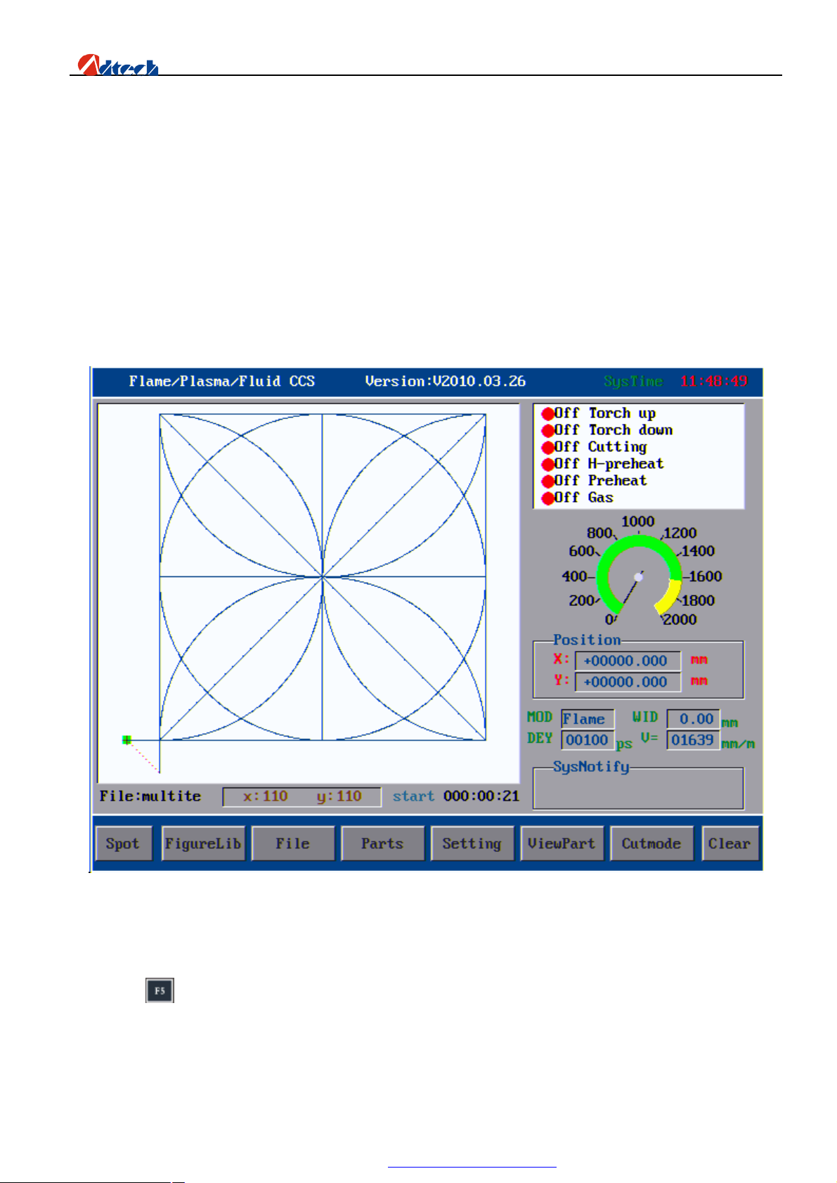
HC6500 flame cutting control system will show the following start-up interface once started, which is also the
main interface of system processing. For detailed functions, please refer to the future chapters.
Operation processes are demonstrated as follows:
Before processing, it is required to check the parameter settings and system. To set all basic parameters, you can press
function key in the main interface to enter parameter setting interface as follows:
9
PDF 文件使用 "pdfFactory Pro" 试用版本创建 www.fineprint.com.cn
Page 11
ADT-HC6500 Flame/Plasma/Fluid Controller
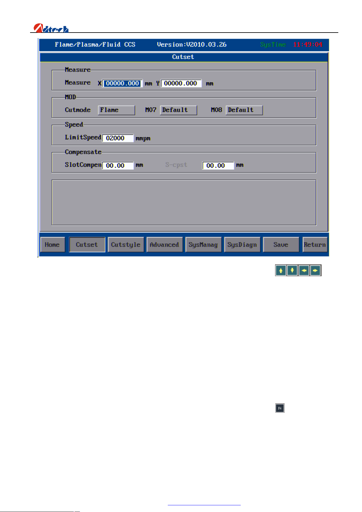
You can set the parameters one by one in this interface according to the requirements. Pressing on the
key panel is to select the parameter on which the cursor is located. Here we will explain these parameters respectively:
Board size: It is set to ensure that the cutting torch would not exceed the steel plate during the cutting. This parameter
should be set if you use controller to load material by figure. If it is set to be 0, the system would not have restriction on
the relation of steel plate size and cutting figure. Here we set X and Y both as 0.
Cutting mode: Plasma cutting and flame cutting are available at the moment. Here we set it as flame cutting.
M07, M08: It is the cutting process selection. Default refers to the default cutting mode provided by the system. If
user-defined is selected, you can set the cutting processes as you like. Here, we set it as default.
Processing limit speed: It refers to the maximum speed of cutting during the processing. Practical processing
speed=Limited speed*Speed percentage. Here we set it as 2000mm/minute.
Gap compensation: It refers to the width of cutting gap. Here we set it as 1.5MM. Mark compensation (Not available)
is set similar to the gap compensation, whose actual value needs to be measured.
If you want to save the settings once all parameters in the interface have been set, you can press key, and the system
will pop up a prompt indicating “Parameters are saved, press any key to return”. Press any key to return. At this time,
the setting of parameters in main interface is finished.
10
PDF 文件使用 "pdfFactory Pro" 试用版本创建 www.fineprint.com.cn
Page 12
ADT-HC6500 Flame/Plasma/Fluid Controller
Ø Quick I/Q Test
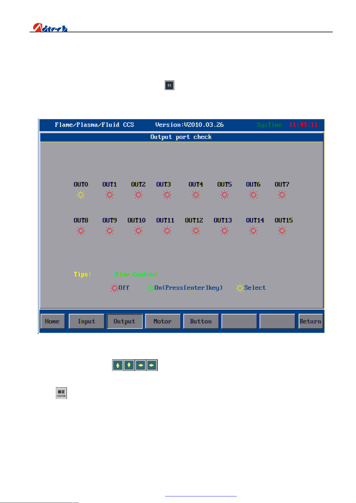
Next, we are going to test the system I/O. Press the key in cutting setup interface to enter the interface of system
diagnosis.
The following picture shows the interface of output port diagnosis:
In this interface, you can press to move the cursor to the relevant output. You can setting Port No.
in the “Advanced Setup”. When you choose the Ports, System will auto-remind the Port No. if the Ports had been set.
And press to confirm. If the system wiring is in good condition, there will be a level output in the relevant output
of cutter; and if the wiring is wrong, the level will be exported in a wrong output.
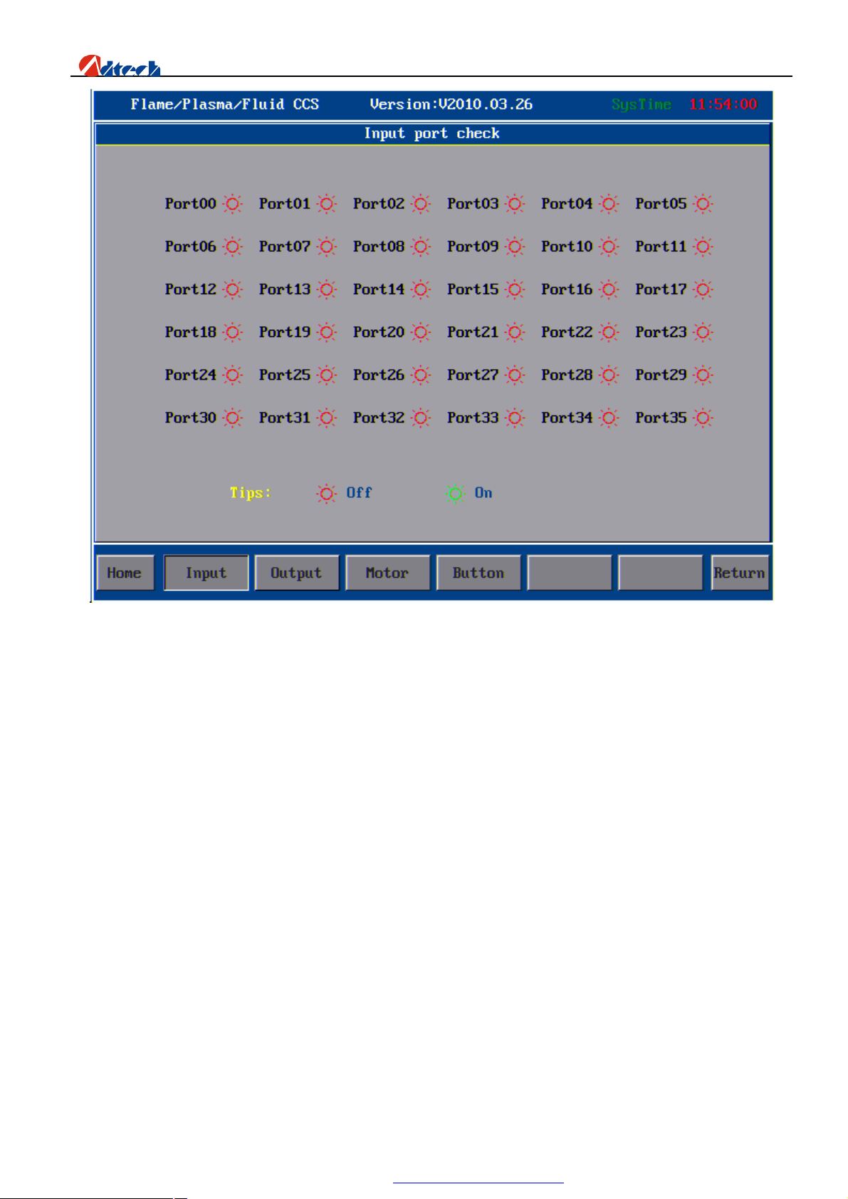
The following picture shows the interface of input port diagnosis:
11
PDF 文件使用 "pdfFactory Pro" 试用版本创建 www.fineprint.com.cn
Page 13
ADT-HC6500 Flame/Plasma/Fluid Controller
The logic of output is just opposite to that of input. When there is an input, a green analog light will be on in the
relevant port indicating that it is closed, as the above picture shows. If the wiring is wrong, it will show the connection
info in the wrong position.
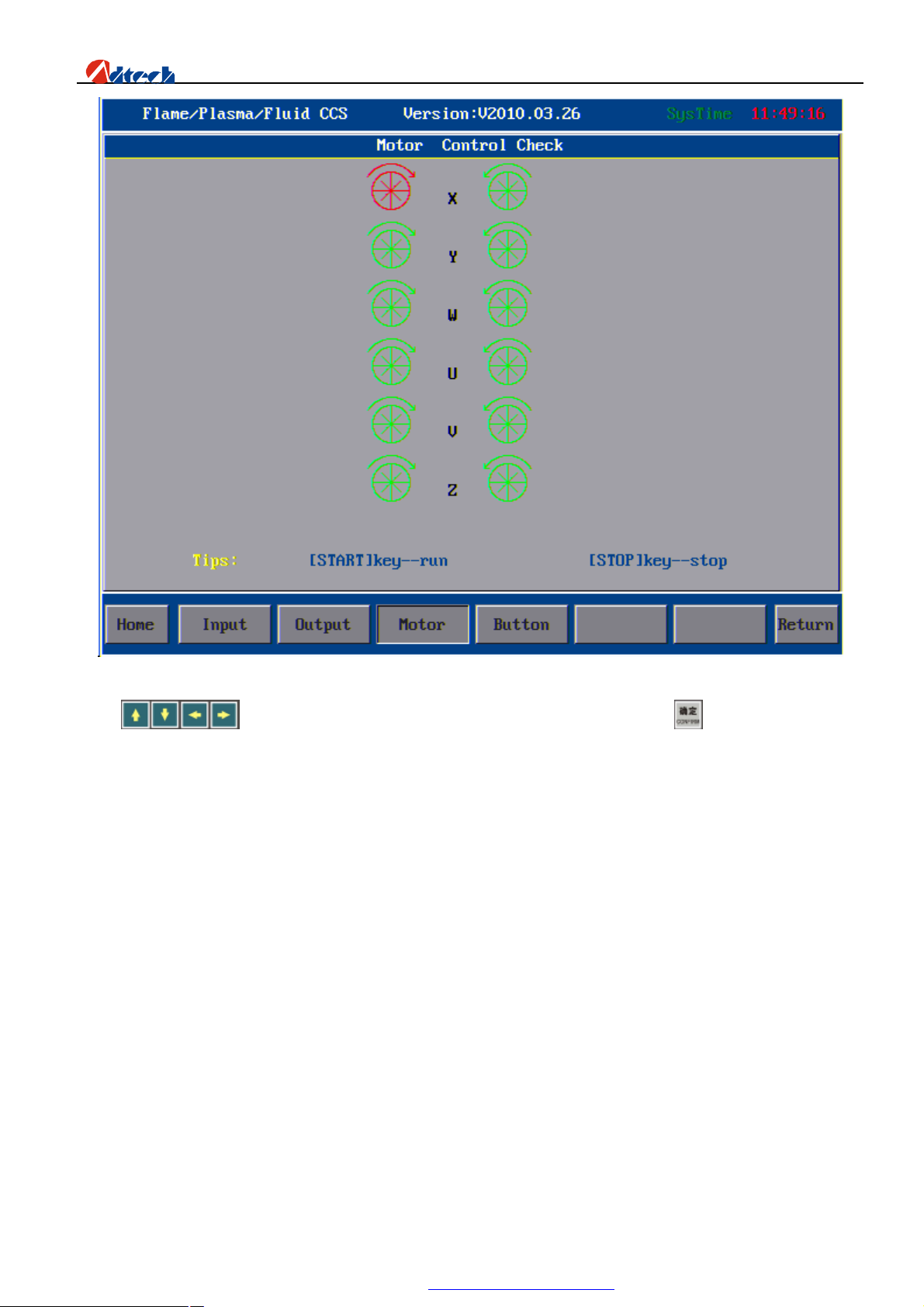
Motor diagnosis: It is to check whether the wiring of motor is correct. The interface is shown as follows:
12
PDF 文件使用 "pdfFactory Pro" 试用版本创建 www.fineprint.com.cn
Page 14
ADT-HC6500 Flame/Plasma/Fluid Controller
Press to move the cursor on the corresponding motor axis and press the key, the relevant motor
will then receive the command and start rotating; CW (clockwise) is representative positive direction
. If the rotation direction is wrong, you should change the wiring of this axis until there is no problem any more.
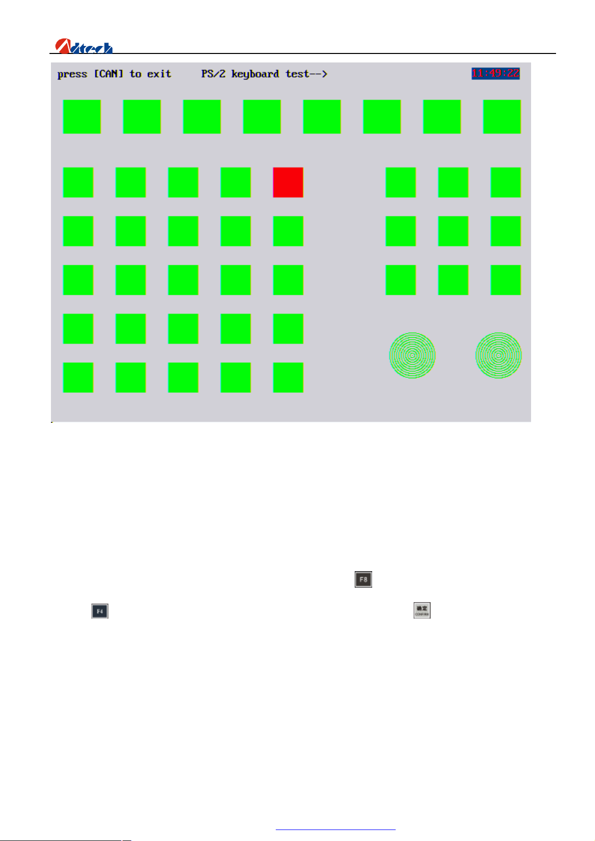
Key test: It is to check whether the system key is in good condition or not. The interface is shown as follows:
13
PDF 文件使用 "pdfFactory Pro" 试用版本创建 www.fineprint.com.cn
Page 15
ADT-HC6500 Flame/Plasma/Fluid Controller
There will be a response relatively on the interface if you press a key on the panel. If there is no response when you
press a key, it means this key is out of order.
Until now, the diagnosis of system I/O is finished.
Ø Speed setup
If the system wiring and diagnosis are in good condition, you can press key to exit the cutting setup interface. You
can press key to enter the advanced setup. Input password “360” and press the key to enter the interface of
password parameters as follows:
14
PDF 文件使用 "pdfFactory Pro" 试用版本创建 www.fineprint.com.cn
Page 16
ADT-HC6500 Flame/Plasma/Fluid Controller
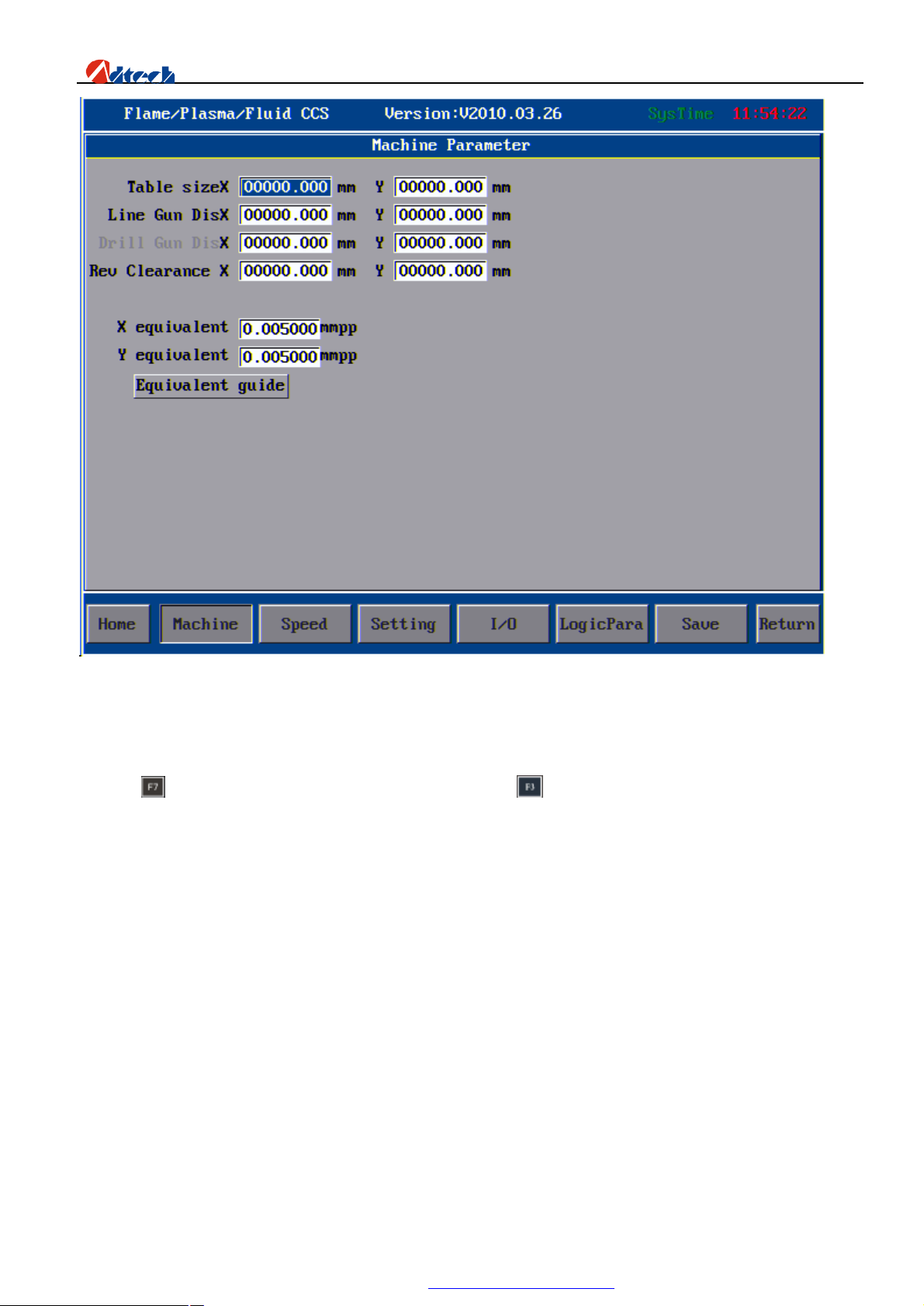
The above is the interface of system parameter setup. Here, only direction clearance needs to be set, other parameters
adopt the default value. If the system does not have clearance, for example the new machine, it can be set as 0. Here we
set X and Y both as 0, the details introduction of impulse equivalent setting is in the behind section of advanced setup
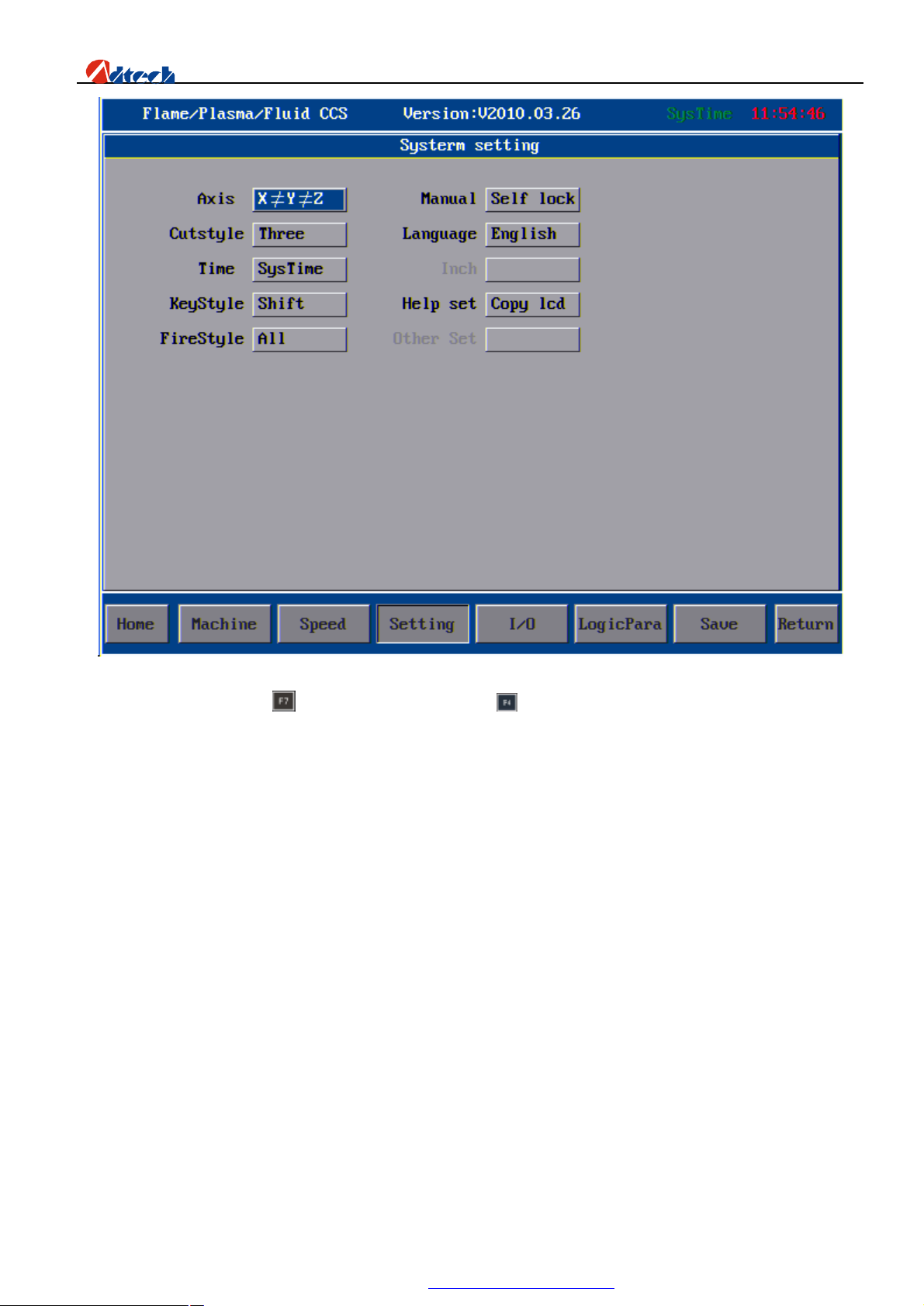
and press key to save the parameters. After that, you can press to set the speed parameters as follows. You just
need to set the start-up speed, acceleration of 1st section, processing limit speed (the same as that in the main interface
of parameter setup), manual limit speed (maximum speed for manual operation), creep speed, and plasma HI/LO speed.
The start-up speed and acceleration of 1st section should be set time and time again until the machine has least or no
vibration, and at the same time they should meet the demand of cutting processes. Here we set the start-up speed as
400mmpm, and the acceleration of 1st section as 50mG. See picture as below:
15
PDF 文件使用 "pdfFactory Pro" 试用版本创建 www.fineprint.com.cn
Page 17
ADT-HC6500 Flame/Plasma/Fluid Controller
After the setup, you can press to save the data, and then press to set other settings of system as follows:
16
PDF 文件使用 "pdfFactory Pro" 试用版本创建 www.fineprint.com.cn
Page 18
ADT-HC6500 Flame/Plasma/Fluid Controller
We take the parameters above as defaults.
Until now, the setting of speed parameter and related parameters is finished.
Ø Quick process setup
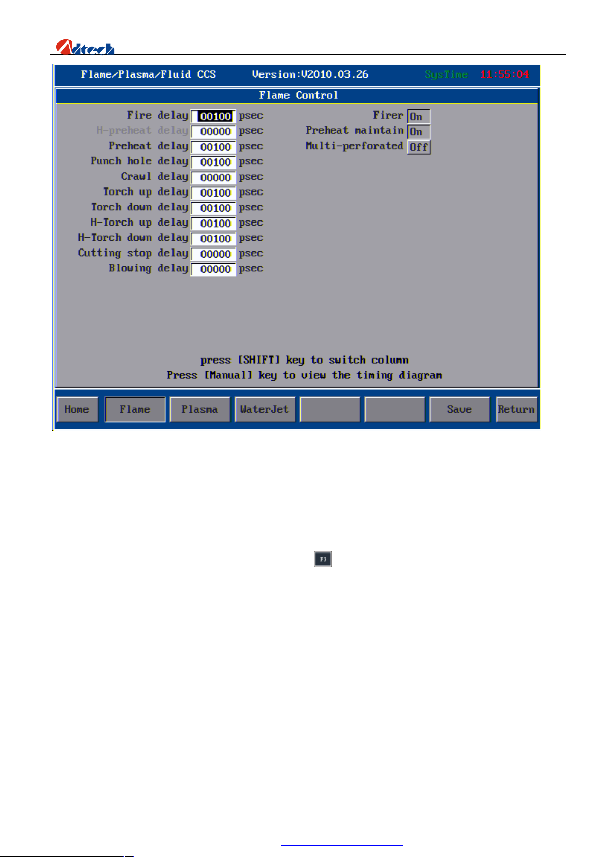
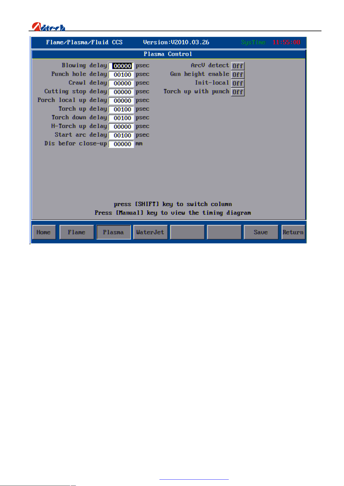
Back to the main interface after the above settings, and press to go to the process setup interface as below to set the
process parameters. Flame cutting and plasma cutting processes are available (Water cutting is a system reserved option,
and is not available for the moment).
Flame:
17
PDF 文件使用 "pdfFactory Pro" 试用版本创建 www.fineprint.com.cn
Page 19
ADT-HC6500 Flame/Plasma/Fluid Controller
Plasma:
18
PDF 文件使用 "pdfFactory Pro" 试用版本创建 www.fineprint.com.cn
Page 20
ADT-HC6500 Flame/Plasma/Fluid Controller
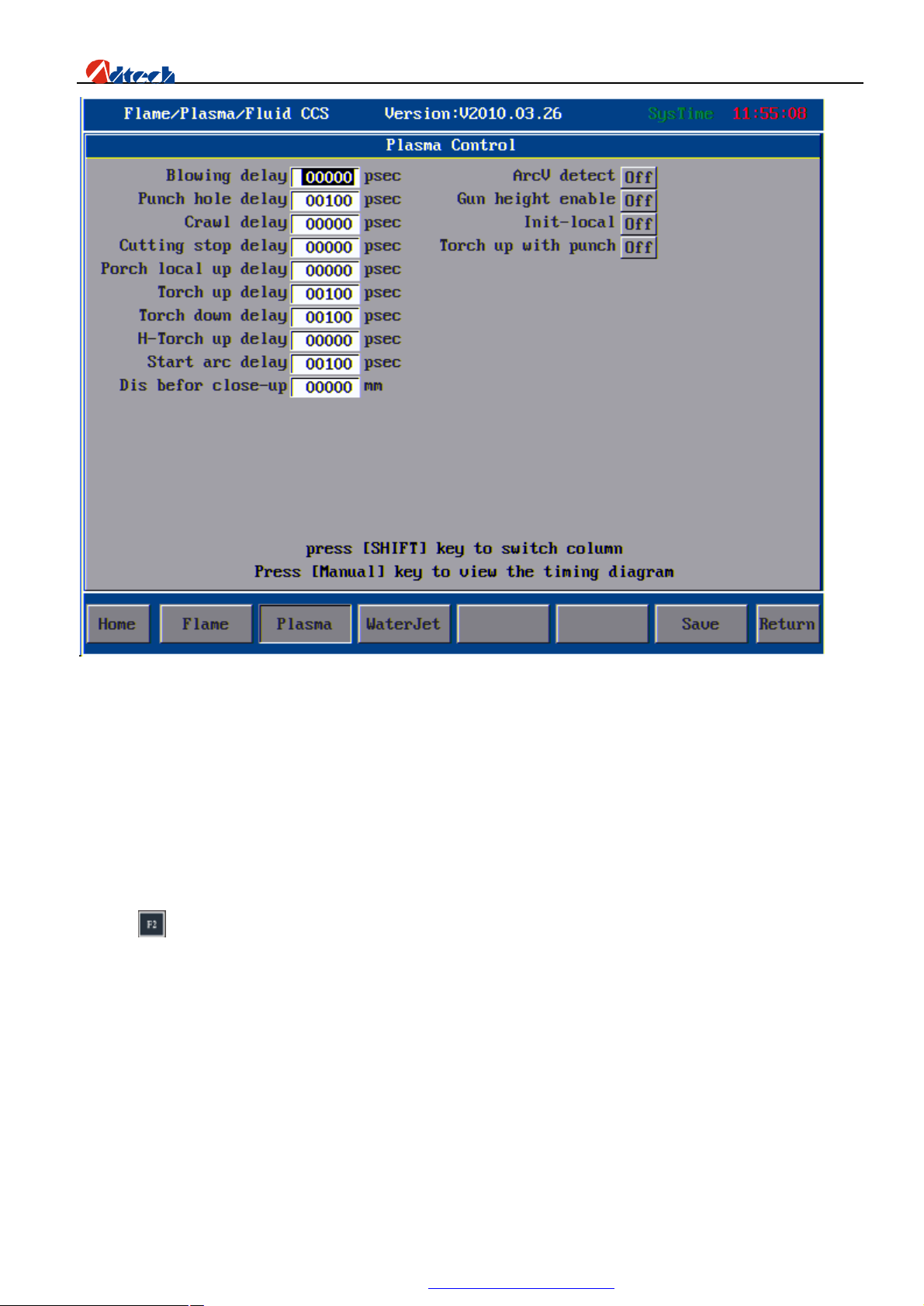
All parameters of flame/plasma process should be set considering various factors including field situation, thickness of
steel plate and board, etc. We will discuss these matters in the coming chapter.
The setting of relevant process parameters is finished.
Ø Quick load of file for processing
Three manners are available:
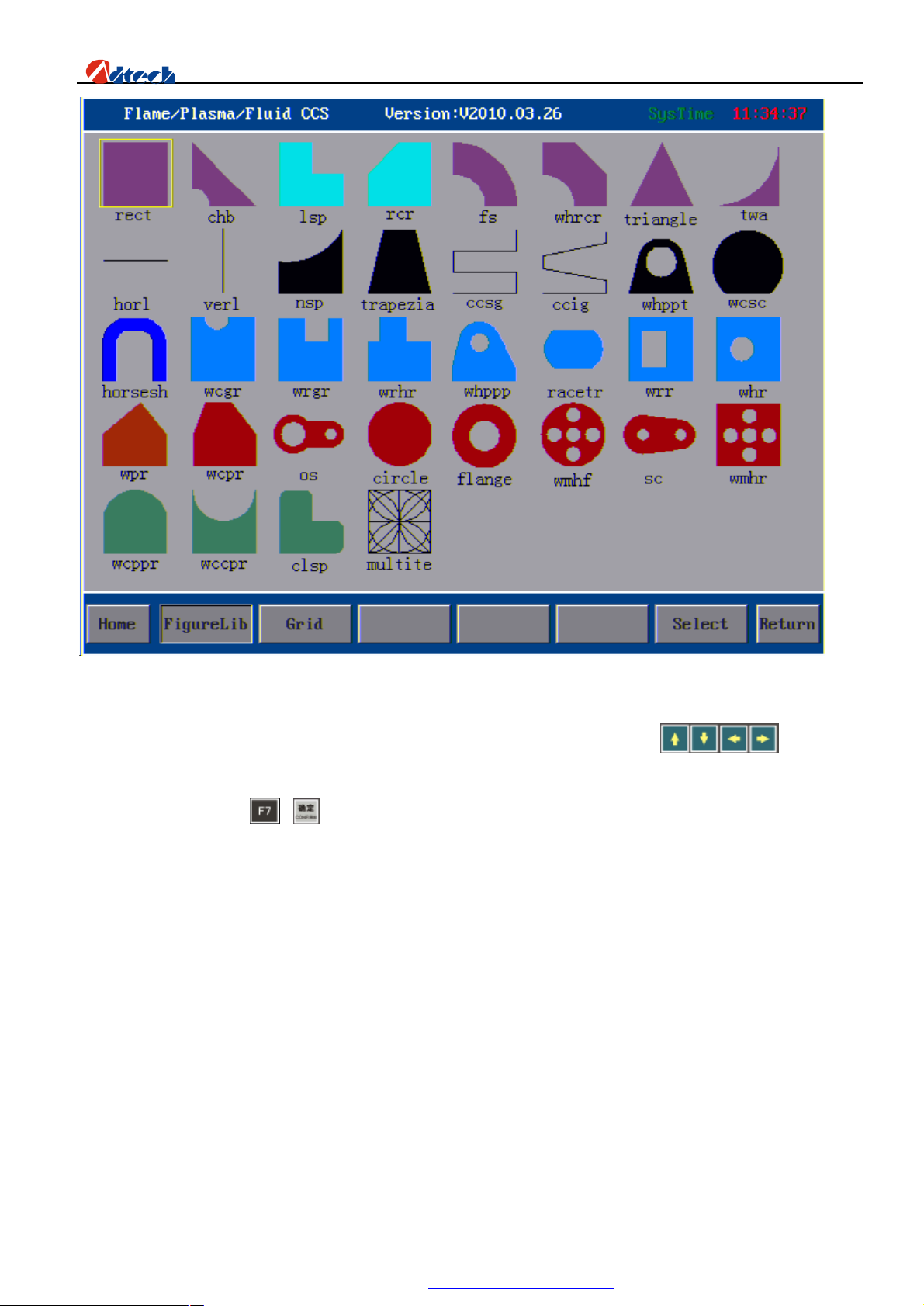
Manner 1: Load processing file from graphic library
Press in main interface to enter the interface of graphic library as follows:
19
PDF 文件使用 "pdfFactory Pro" 试用版本创建 www.fineprint.com.cn
Page 21
ADT-HC6500 Flame/Plasma/Fluid Controller
There are 35 applicable figures and 1 figure for testing in the figure interfaces. Press key, and the
cursor will be moved to the corresponding figure. If you want to process a rectangle, you can move the cursor to
rectangle figure and press or key to confirm. Then, the system will be switched to parameter setup interface of
rectangle as the following picture:
20
PDF 文件使用 "pdfFactory Pro" 试用版本创建 www.fineprint.com.cn
Page 22
ADT-HC6500 Flame/Plasma/Fluid Controller
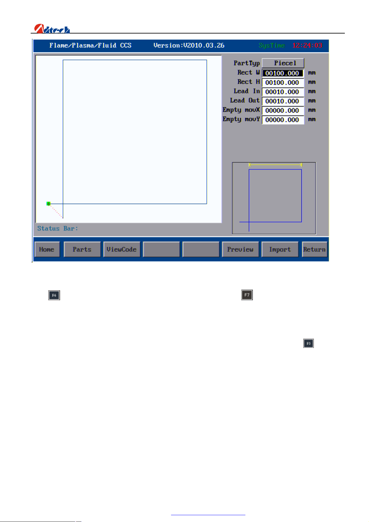
The above is the parameter setup interface of rectangle. When you have set the width, height part and type part, you can
press to preview the figure. If the figure is confirmed correct, you can press to import the figure and the system
will return to the main processing interface automatically. Press the start key in flame cutting mode to start the flame
cutting, or in plasma cutting mode to start the plasma cutting.
Manner 2: Load files from USB disk
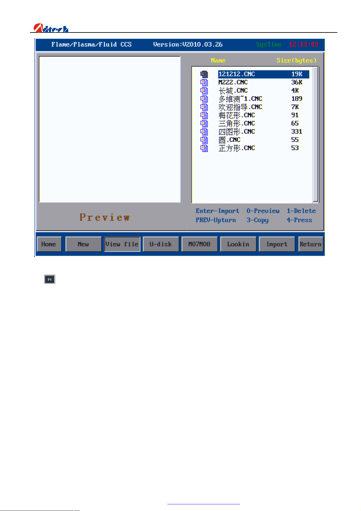
First, insert the USB disk contained with processing files into the USB port of controller, and press in the main
interface to enter the file loading interface as follows:
21
PDF 文件使用 "pdfFactory Pro" 试用版本创建 www.fineprint.com.cn
Page 23
ADT-HC6500 Flame/Plasma/Fluid Controller
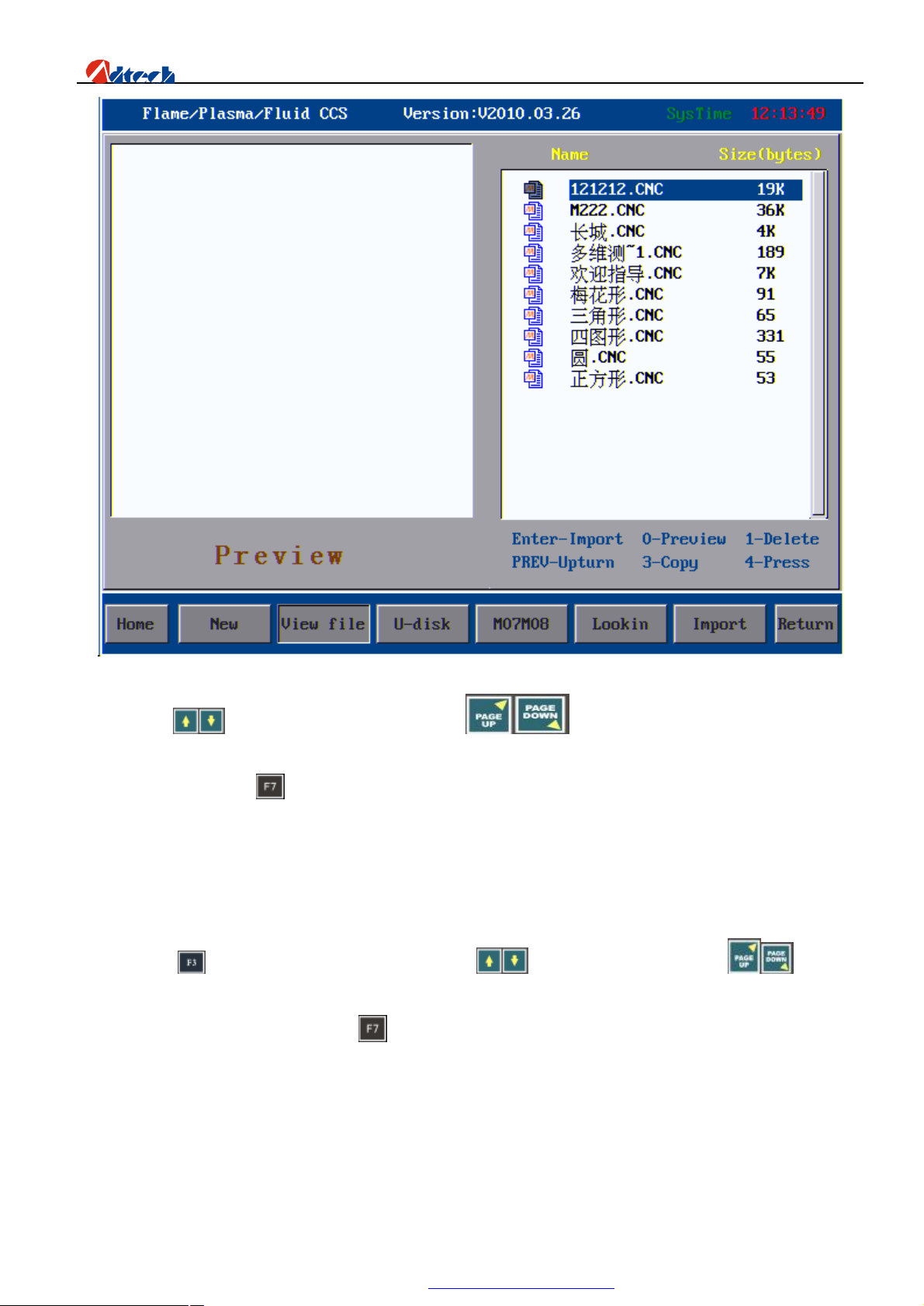
Press key in this interface and the system will start reading the USB disk. After a while, the system will display all
processing files of USB disk as follows:
22
PDF 文件使用 "pdfFactory Pro" 试用版本创建 www.fineprint.com.cn
Page 24
ADT-HC6500 Flame/Plasma/Fluid Controller
You can press key to select in the current page, or key to page up/down. As soon as you have
selected the required file, you can press number key “2” to copy it to the control system, and then load this file from the
system. (Or you can press key directly to load the file. During this operation, the USB disk needs always to be
connected with controller. To avoid bad contact, it is recommended not to do in this way.)
So far, we have finished introducing on how to copy the processing files in USB disk to control system.
Manner 3: Load files from control system
If you have copied files of USB disk to control system, you can then load processing files from the system. In main
interface, press to enter file operating interface, and press to select items within page or to page up
or down until you have found the processing files. If you are not sure about the file, you can press number key “0” to
preview the figure. If you are sure, press key to load the processing file, and the system will jump to the main
processing interface to pre-process the processing code. After that, press the start key in flame cutting mode to start the
flame cutting, or in plasma cutting mode to start the plasma cutting.
Till now, you have known something about the system, and known how to operate a control system in a basic
operation procedure. In the following chapter, we are going to introduce the skills and operating methods in
detail.
23
PDF 文件使用 "pdfFactory Pro" 试用版本创建 www.fineprint.com.cn
Page 25
ADT-HC6500 Flame/Plasma/Fluid Controller
Chapter III System Operating Instructions & Skill
ADT-HC6500 flame/plasma/fluid cutting NCS can be used in machine tool to control flame/fluid or plasma to
process the cutting. The system is displayed in the way of window prompt stage by stage. When entering into an
interface menu, you can press to select the corresponding function, and press Key to return
to the Main Menu or key to return to the previous menu.
Ø Auto
Main window
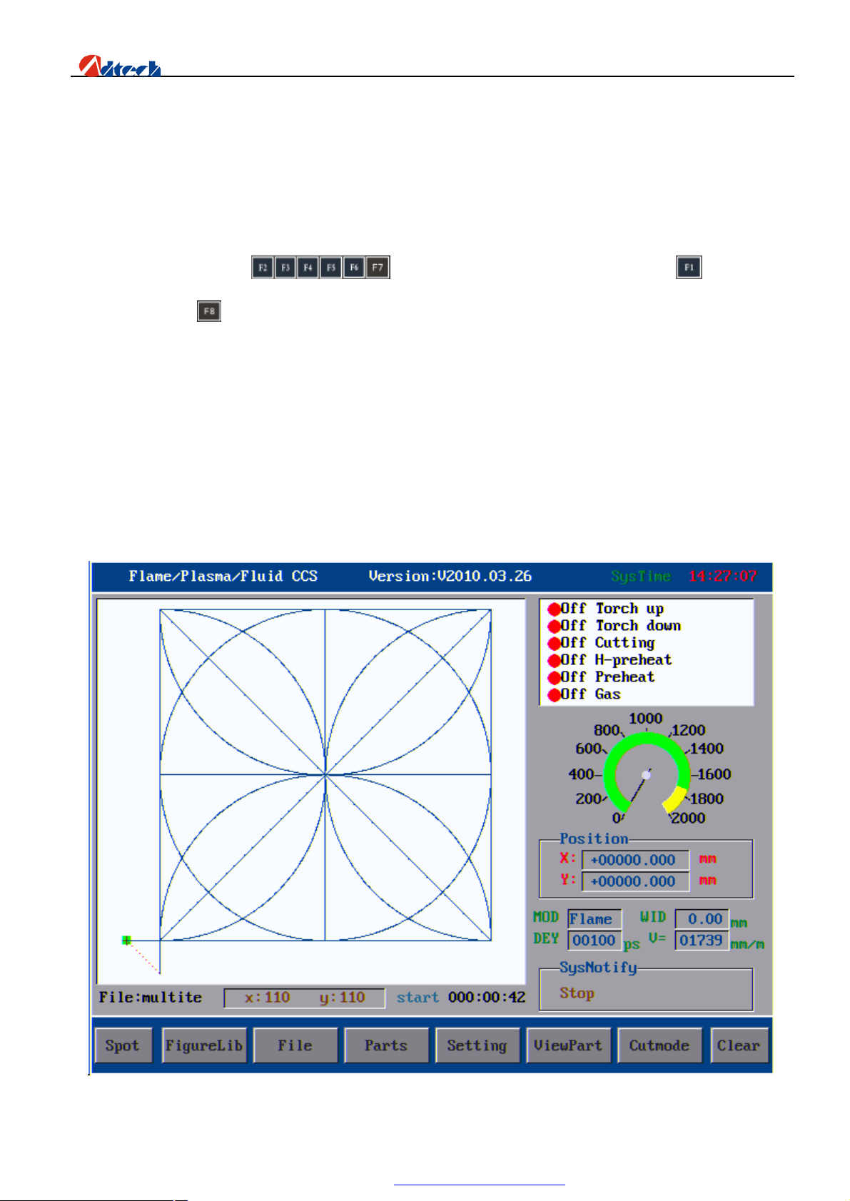
The first interface the system enters into is the main processing interface. As picture shown below:
Main window
24
PDF 文件使用 "pdfFactory Pro" 试用版本创建 www.fineprint.com.cn
Page 26

ADT-HC6500 Flame/Plasma/Fluid Controller
Main window is the first window after the start-up, including two parts, menu and current interface function. We are
going to introduce the menu and window below.
Break point
If the system encounters power failure during the processing, do not move the cutting torch, you can press break
point key (or you need not pressing this key, the system will be restored automatically) to continue processing after the
power restoration, reducing and saving the cutting board.
Graphic management
In the graphic management interface, you can select part from graphic library, edit part code, rotate the array of part, set
the parameters, and carry out grid edge-sharing cut. For details, please refer to the coming chapter.
File management
In file management interface, you can read files from controller or USB disk, create new file, edit the file, test code,
preview figure, and define M07 and M08 instructions. For details, please refer to the coming chapter.
Part options
This option enables you to mirror, rotate, array, calibrate, zoom in/out, and restore the processing part. For details,
please refer to the coming chapter.
Setup options
You can press this key to set all control-related parameters, process, and other settings. For details, please refer to the
coming chapter.
Partial view
This is to view the partial section of a part. In partial view, you can press to move the figure up,
down, left or right, or you can press the number key on keyboard to view the figure at the corresponding multiple. In
overall view, you are going to move the cutting torch up, down, left or right if you press key. In addition,
other four direction moving functions are extended. Number key is not available in overall view. For
other application, please refer to the coming chapter.
Cutting mode
This is to switch the cutting mode. Currently, three cutting processes (flame cutting, plasma cutting and preview) are
available.
Interface explanation
1. In preview interface, there will be a cutting figure, the relevant file name of current figure at the left bottom
corner, next to which are width and height of part figure in unit “mm”.
2. The top right corner is the output control setting, indicating the control status of flame and plasma output.
Red light indicates off, and green light indicates on.
25
PDF 文件使用 "pdfFactory Pro" 试用版本创建 www.fineprint.com.cn
Page 27

ADT-HC6500 Flame/Plasma/Fluid Controller
3. Speedometer shows the instant travel speed of the cutting torch. The maximum value is the limited value of
processing speed.
4. Position coordinate: It shows the relative coordinate of current position to origin.
5. Cutting mode: Flame, plasma, and preview are available. Gap: It indicates the current gap compensation
value. Delay: It refers to delay during the cutting, such as preheating delay. Speed: Set the processing speed.
6. System prompt: Show all the current states.
7. Duration time shows the total time of your current application. The system time refers to the normal time.
8. You can set the speed, pre-heating time in the main interface. To do this, press in main interface in standby
mode, the cursor will jump to speed setup window when you can then set the speed and pre-heating delay. After
the setting, press this key again, and the system will verify the rationality of parameter and save the data.
Note: The speed parameter is calculated in a certain rule according to the parameters you set, and the rationality of
parameters is verified. If the speed parameter does not meet the system requirement, the system will adjust it according
to your set value, which as a result that your set parameter may be different from the actual value. This is normal. You
can also press key to set the speed parameter by adjusting the speed percentage. Delay parameter can also be set
in parameter setting other than in this way. This will be introduced in the coming chapter.
Pause
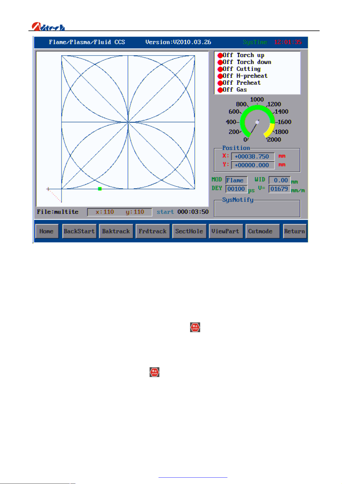
Another interface shows as you press pause key:
26
PDF 文件使用 "pdfFactory Pro" 试用版本创建 www.fineprint.com.cn
Page 28
ADT-HC6500 Flame/Plasma/Fluid Controller
Interface after you have pressed pause key
Back to origin
Press this key, and the cutting torch will return to the processing starting point (relative origin of coordinates).
Back along route
Return to processing starting point along the route. If you press key or press this key again, the motion will be
stopped or suspended.
Forward along route
Travel forward along the route. If you press key or press this key again, the motion will be stopped.
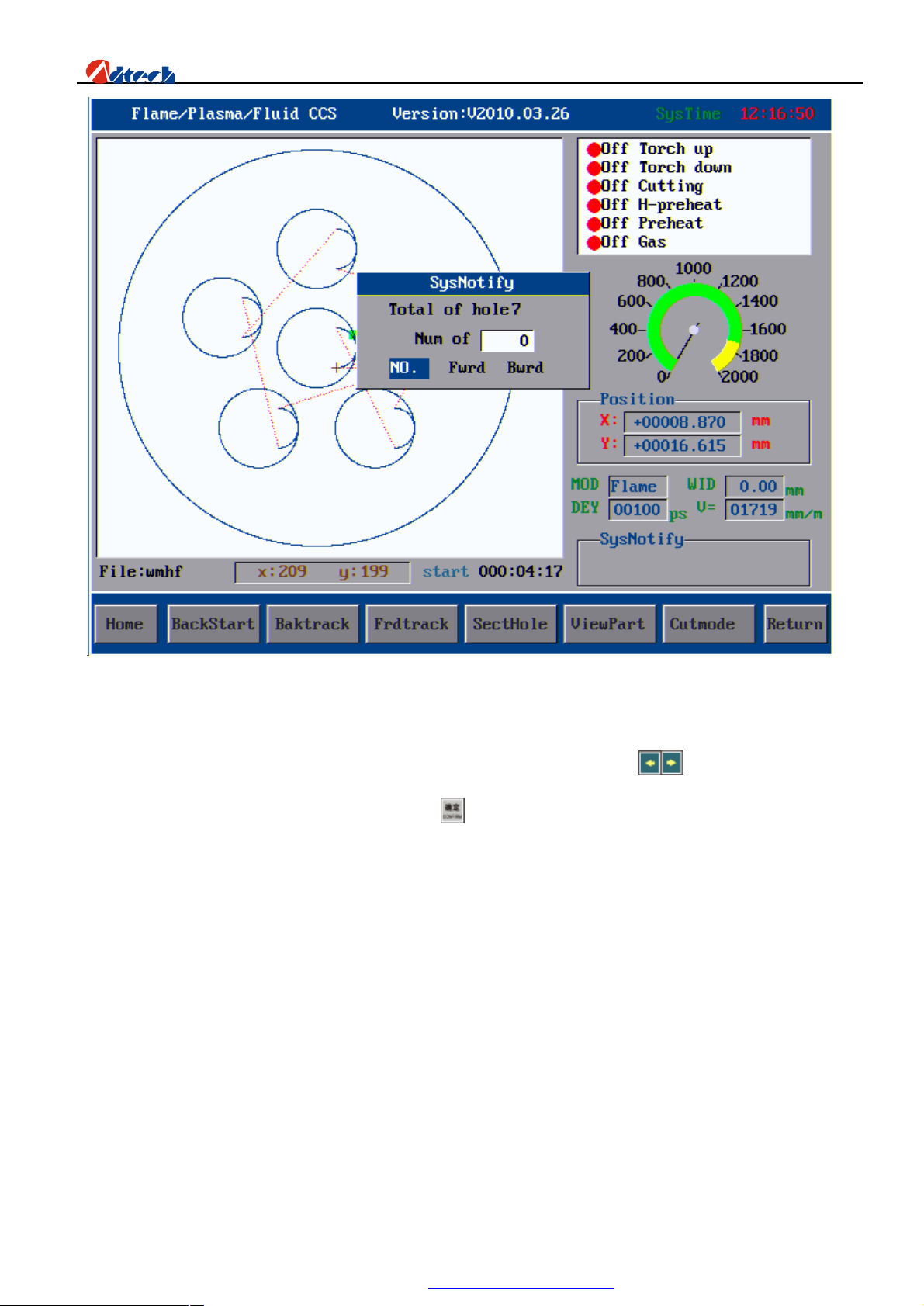
Choose perforating point
Choose the perforating point, number of back-off perforating point, number of forwarding perforating point, and
the number of perforating point selected following the SN. See picture as follows:
27
PDF 文件使用 "pdfFactory Pro" 试用版本创建 www.fineprint.com.cn
Page 29
ADT-HC6500 Flame/Plasma/Fluid Controller
Choose perforating point
The above interface is to choose the numbers of perforating points. You can press key to choose from “SN”,
“Forwarding”, and “Back-off”. Input the data and press key, the system will prompt to choose “Cutting torch located
at origin” or “Cutting torch located at current point”. At this time, you can move the cursor to select the related option
to choose the perforating point.
Note: “Cutting torch located at origin”—indicating the cutting torch is located at origin. When you have chosen the
perforating point, the cutting point and cutting torch will be moved to the selected perforating point.
“Cutting torch located at current point”—indicating the cutting torch would stay at the current position. When
you have chosen the perforating point, the cutting torch does not move but the cutting point moves. Once you start
processing or other operations, the cutting torch will move forwards or backwards from the current position.
Basic operations
Preview: The system only runs X and Y tracks. The output switches, such as preheating oxygen or
gas and cutting control, would not be opened. It is used to preview whether the track and the size of running
28
PDF 文件使用 "pdfFactory Pro" 试用版本创建 www.fineprint.com.cn
Page 30
ADT-HC6500 Flame/Plasma/Fluid Controller
steel plate are correct.
Flame: The system is performing the flame cutting.
Plasma: The system is performing the plasma cutting.
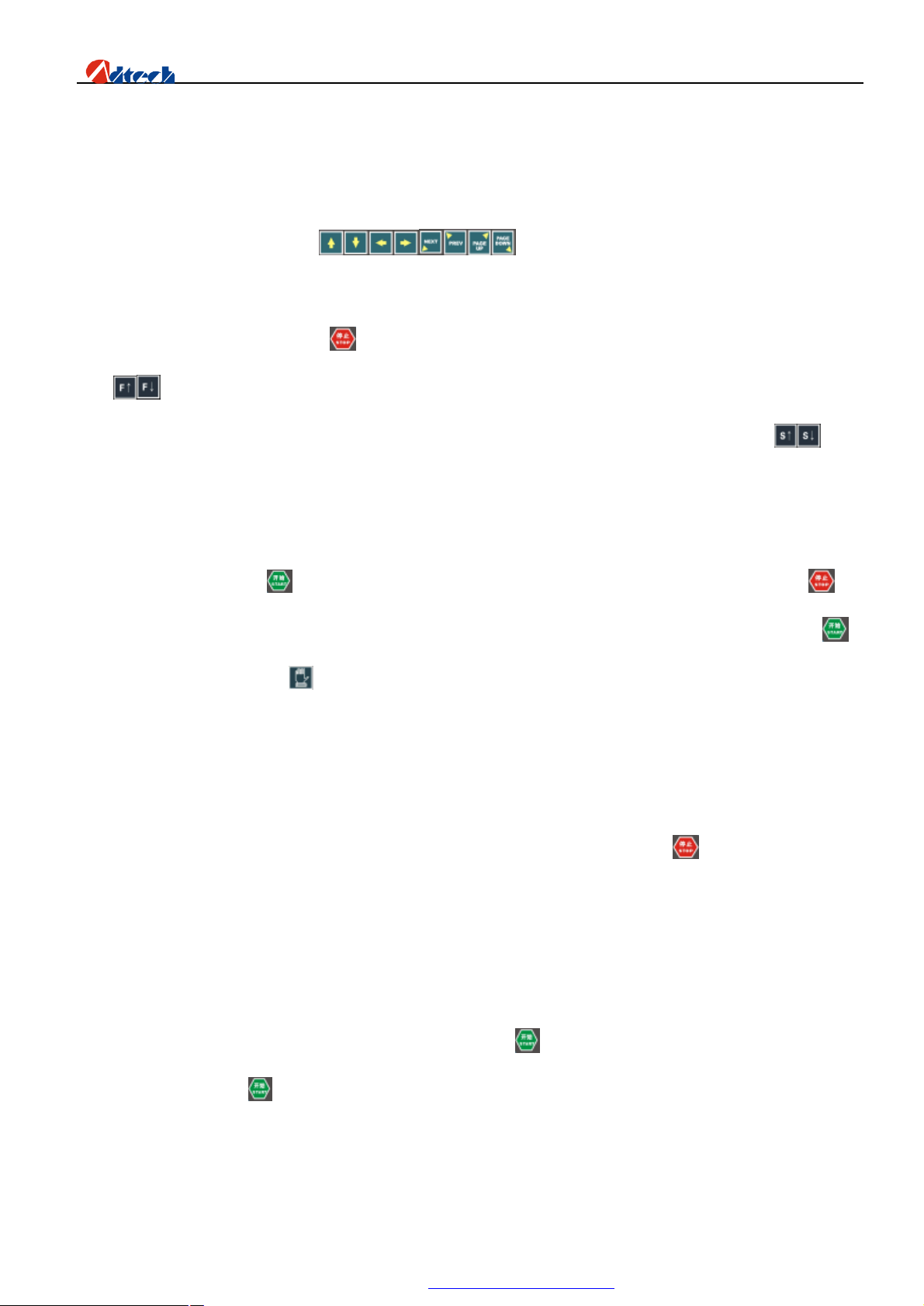
In Partial View state, you can press key to move the figure in eight directions, and press
0-9 number keys to zoom in figure at corresponding multiple. In Overall View state, you can press these eight keys to
move the cutting torch in eight directions. The cutting torch stops when you lift your hands at the inching condition, or
when you press this key again or press key if it is at self-locking condition.
Press key to increase or decrease the speed percentage by 1% for each time. If you press and hold the key, the
speed will be increased or decreased by 1% without stop until you release the key. You can press and hold key to
lift up or drop the cutting torch.
Preheating delay
When you are performing the preheating, the total preheating time and elapsed time will be shown at the right bottom
of the interface. If you press key, the system will stop the preheating and perform the next act. If you press key,
the system will extend the preheating time without limit; and if the preheating time is long enough, you can press to
stop the preheating. If you press key in the middle of direction keys, the system will save the current preheating time
automatically as the future standards.
Clear: It is to set the current position as the reference origin, and you can then see the cursor position of preview
window. It is used to get back the coordinate origin and clear the memory position of current processing.
Back to origin: It allows the cutting torch line to get back origin. It can be used to quickly get back to the relative
origin. You can press this key if you want to return to origin during the processing, or press key if you want to stop.
Back along route: Back to origin relative to the straight line. It is a function for the cutting torch to return to the origin
along cutting track. It is usually used if you want to return to cut again when the materials are not completely cut, or to
get back to origin.
Forward along route: Travel forward along the processing route without performing cutting. It is usually used to skip
the current track or preview.
Choose perforating point: It is used to skip one or several perforating points to cut directly.
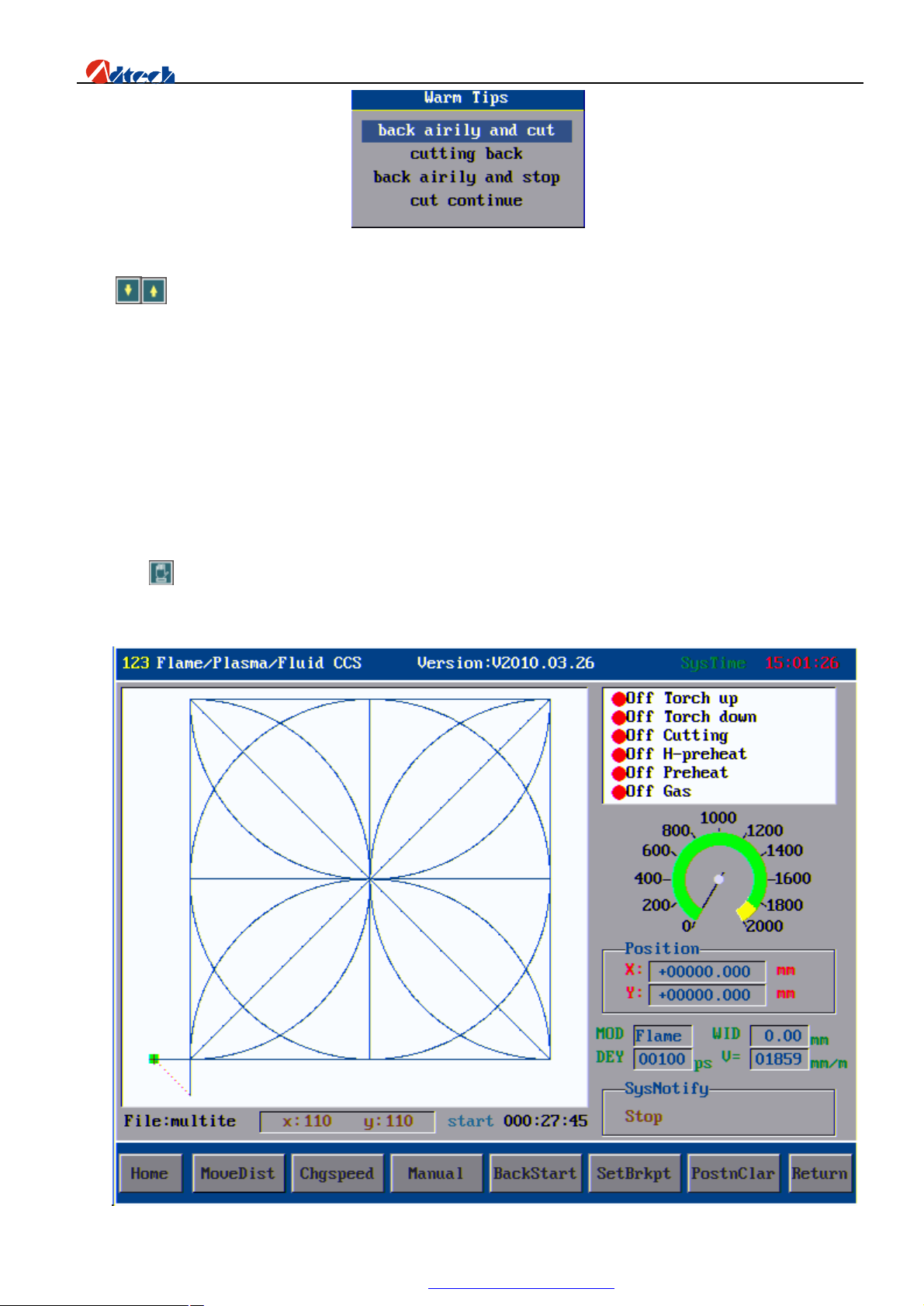
Start: When the cutting torch is on moving track, you can press key to start cutting along the track. If the cutting
torch is out of track, press key and a prompt box will be shown as follows:
29
PDF 文件使用 "pdfFactory Pro" 试用版本创建 www.fineprint.com.cn
Page 31
ADT-HC6500 Flame/Plasma/Fluid Controller
Press key and the cursor will be moved to option as indicated in picture such as “Idle stroke back and
cut”, which means the cutting torch will return to the cutting track automatically and start perforating and cutting.
“Cut directly and return” means to perforate at the current position and cut. “Idle stroke back and stop” means the
cutting torch will stop when idling traveling to part track. “Continue from the current point” means to cut the
next figure from the track you are moving, but the reference point is no longer the original reference point.
Ø Manual
Press key in main interface, and the system will go to manual mode. The state window is as follows:
30
PDF 文件使用 "pdfFactory Pro" 试用版本创建 www.fineprint.com.cn
Page 32
ADT-HC6500 Flame/Plasma/Fluid Controller
Interface of Manual Operation
Interface explanation
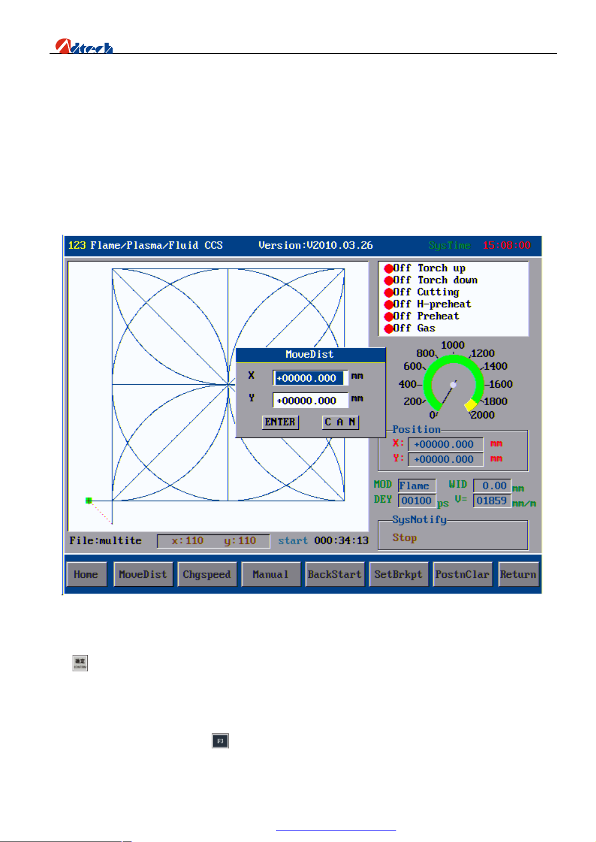
Apart from function keys on the bottom and the manual speed, the interface of manual mode is similar to that of
auto mode.
Travel distance
The interface is as follows:
Interface of Travel Distance
This function is to set the proper moving distance for the cutting torch. Use the number key to set the distance, and
press key to confirm, the cutting torch will then travel the corresponding distance.
Speed shift: It is used to change the speed of manual travel quickly, which is divided into three grades,
high, medium and low. These grades are defined in the speed settings, ranging at 30%, 60% and 90% of the
limited manual speed. You can press key to quickly switch among these three grades.
Note: Because travel speed and the up/down/left/right moving speed in auto mode also use this speed, you have to
31
PDF 文件使用 "pdfFactory Pro" 试用版本创建 www.fineprint.com.cn
Page 33
ADT-HC6500 Flame/Plasma/Fluid Controller
set the speed percentage in manual mode interface apart from setting the processing speed in auto mode interface.
Generally, the travel speed is faster than the processing speed.
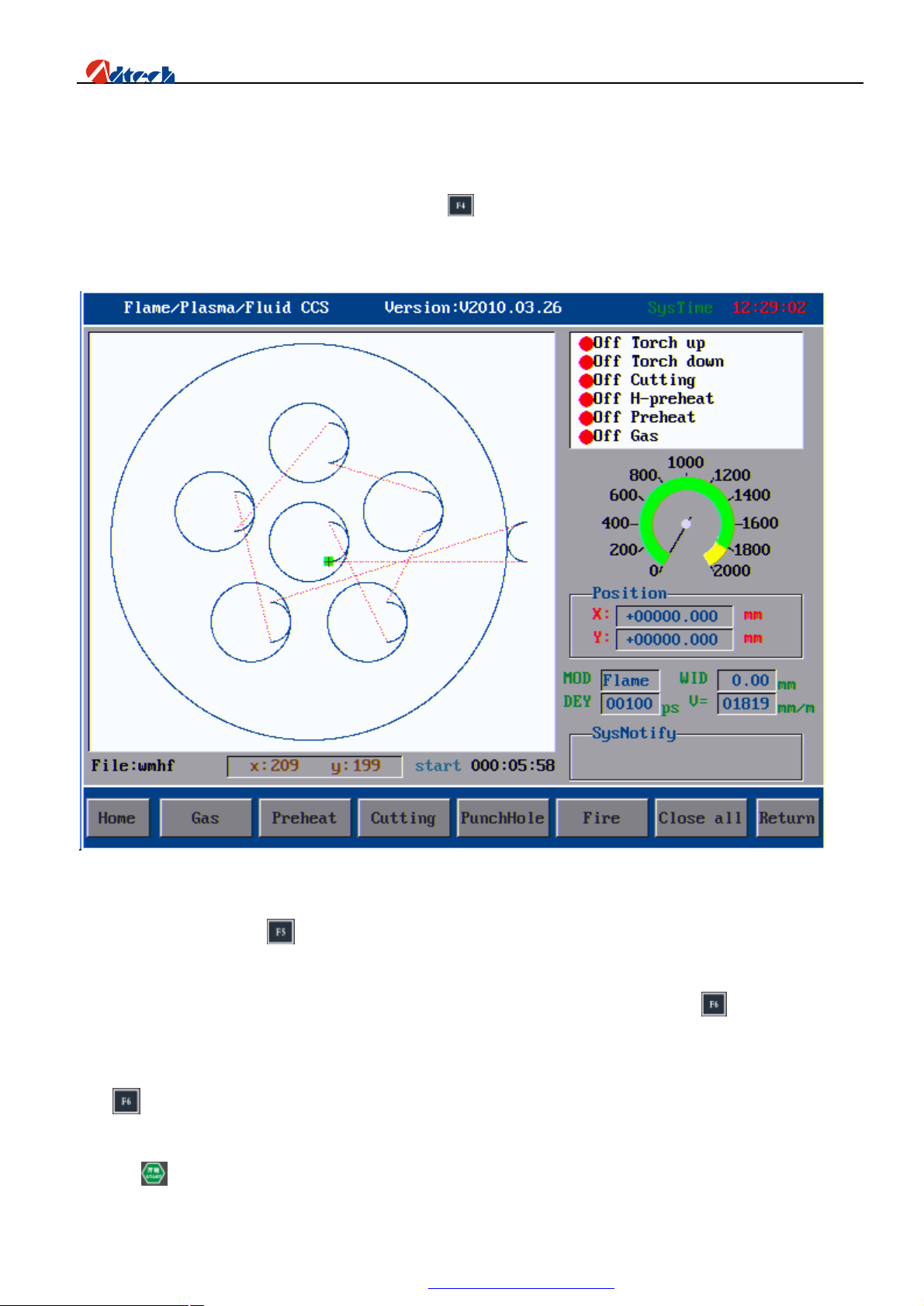
Manual options: It offers options for opening all output ports manually. For example, the corresponding
output of cutting control will be opened if you press key (cutting control), or closed if you press it again. The
interface of manual options is shown as follows:
Manual options
Back to origin: Press in the main interface of manual mode, and the cutting torch will return to reference
origin of parts. It is used to get back to origin in auto mode.
Set breakpoint: When you pause in auto processing, enter the manual mode and press key, the system will
save the current track (the current position of cutting torch) as a breakpoint automatically. This breakpoint is saved
permanently no matter the machine is on or off. When you start the machine or enter the auto mode again, you can
press key in manual mode to restore the breakpoint as long as the current program has not changed. Once you found
the breakpoint, the system will prompt “Breakpoint memory function is enabled”, you can then switch to main interface
and press key to go on processing from the breakpoint. This function is similar to the breakpoint function in auto
32
PDF 文件使用 "pdfFactory Pro" 试用版本创建 www.fineprint.com.cn
Page 34
ADT-HC6500 Flame/Plasma/Fluid Controller
mode.
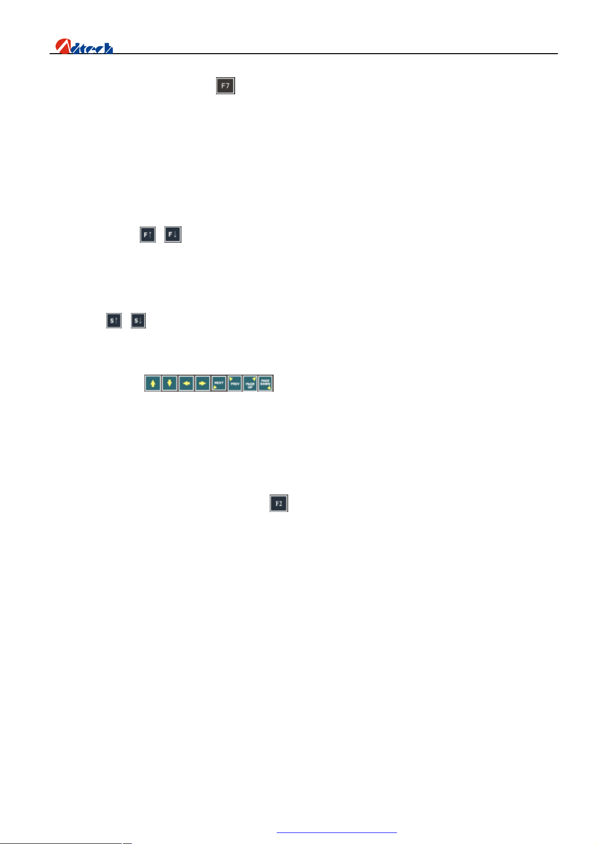
Clear coordinate: When you press key, the X and Y coordinates will be cleared, that is, the current
coordinate will be used as the origin. This function is similar to clear function in auto mode.
Basic operations
1. You can press or key to increase or decrease the cutting speed. The speed will be increased or
decreased without stop if you press and hold the key in standby mode. If you press these keys during the
processing, the speed will be increased or decreased by 1% each time.
2. Press or key, the cutting nozzle will be traveled upwards or downwards. It will stop if you release
the key.
3. You can press to operate the cutting torch in eight directions.
Ø Graphic management
Graphic macro library
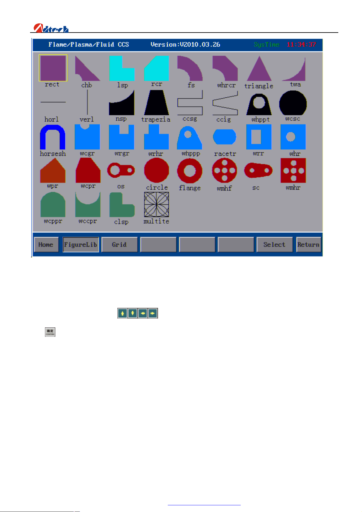
In main processing interface, you can press key to enter graphic management interface, where there are 35
common figures and one testing figures, as shown below:
33
PDF 文件使用 "pdfFactory Pro" 试用版本创建 www.fineprint.com.cn
Page 35
ADT-HC6500 Flame/Plasma/Fluid Controller
Main interface of Graphic macro library
In main interface, you can press F2 key to enter graphic library interface, where there are 35 part figures and
one testing figures. You can press to select the figures. When you have selected the figure, you can
press key to set the graphic library.
Here we take a figure as an example as follows:
34
PDF 文件使用 "pdfFactory Pro" 试用版本创建 www.fineprint.com.cn
Page 36
ADT-HC6500 Flame/Plasma/Fluid Controller
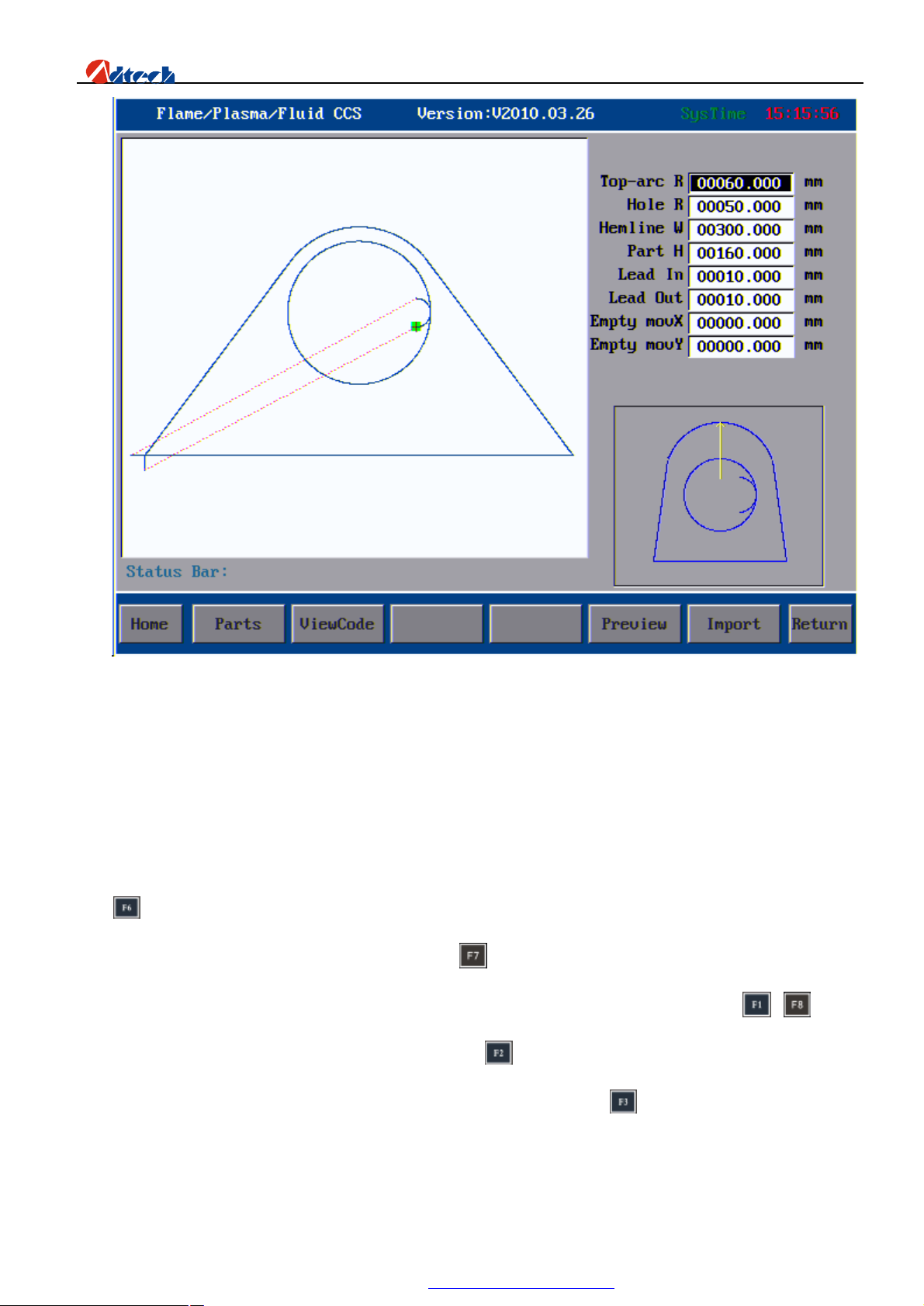
Convex polygon with hole
This figure can be regarded as consisting of half rectangle, an isosceles trapezoid, a section of circular arc, and a
circle. Users can get different processing figure by setting different parameters. The radius of the circular hole can be
set as zero if the hole is not demanded. If needed, the height of the bottom rectangle can also be set as zero. The radius
of the top circle and the height to the center of the circular hole should be larger than the radius of the circular hole.
Press to preview when you have set the parameter. The system will pop out error information at the right bottom if
the parameter is not correct, and reset the parameter. Press to save the setup if there is no mistake, and save the set
processing file in the drive. This processing file can be used directly in the auto interface. If you press or key,
the processing files in the system would not be changed. Press key in this interface, you will enter the part options
interface where you can rotate the array, rotate or zoom in the figure. If you press key, you can view the code of
this part, and the default file is the current file, on which you can edit, test, and preview figure, etc.
35
PDF 文件使用 "pdfFactory Pro" 试用版本创建 www.fineprint.com.cn
Page 37
ADT-HC6500 Flame/Plasma/Fluid Controller
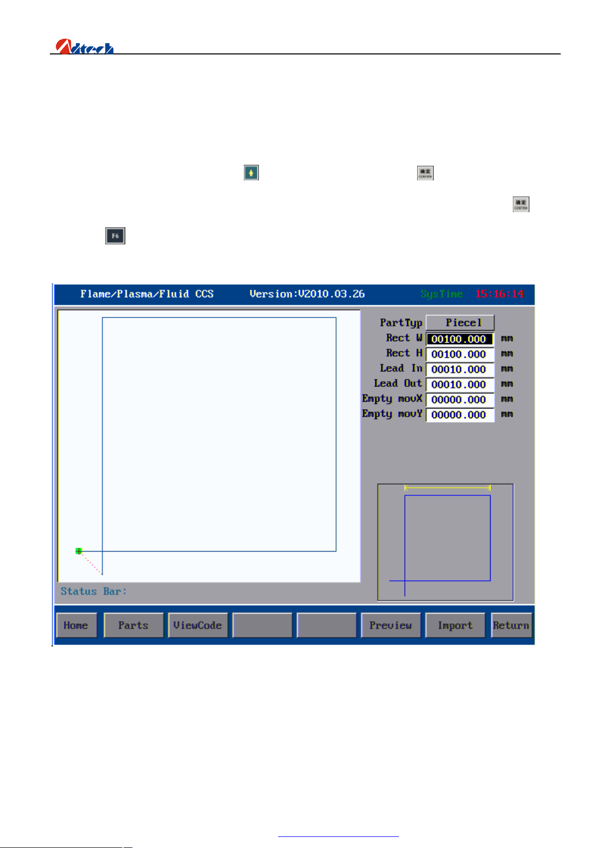
Plate & hole Cutting
Some simply graphs like Rectangular, Triangular, you will find an option “Parts” after you enter to the
graph. There are two types cutting way: Plate & hole parts cutting. You can cut a rectangular hole in the big
steel plate parts. (Punching inside of Rectangular); you also can cut a rectangular plate in the steel plate
(Punching outside of Rectangular); Press changed to “Parts” option, press key is representative you
choose it. Then, you will find the behind of parameters of graphic guide is changed, you can press key to
confirm or key to preview, if you need preview the effect of parameter graph.
Operation skills
The parameter setup in graphic library is based on features of parts, and has a certain restriction. The radius of the
circular hole should not be larger than the radius of the circular arc, and the height from the center of circular hole to
the base line of the trapezoid. The length of the bottom line of trapezoid should not be smaller than twice of top arc
radius. That is because these figures cannot form a correct figure combination if the parameter exceeds the set range.
36
PDF 文件使用 "pdfFactory Pro" 试用版本创建 www.fineprint.com.cn
Page 38

ADT-HC6500 Flame/Plasma/Fluid Controller
Press key to preview when you have set the parameter. The system will pop out error information if the parameter
is out of range, and reset the parameter
In case of “Convex polygon with hole” setup, we set the radius of the circular hole to be 00100.000 and press ,
then, the system pops out a dialogue box indicating “Radius of circular arc is too big”, and the parameter is restored to
the original value.
“Radius of inlet arc” is added to prevent the perforating from affecting the processing quality at the edge. Some of
the figures are inlet line. This is to consider the convenience of operations without affecting the cutting quality. “Idle
move X” and “Idle move Y” are available for each figure to make it convenience for the users to set the original
position of the cutting gun.
You can press to delete the last digital number of the current parameter, and press number key to continue to set
the parameter. Press key to clear the parameter, and press and to select the setup parameter.
Grid-Cut
Grid-cut is a special type of cutting, also called grid edge-sharing cut, which can save board to the largest extend and
the cutting time. Different from other parts, it is usually used to load the square board. The parameter setup and
compensation manner are different from normal figure, similar to part array but have some differences with array. You
can press key in graphic management interface to enter grid-cut interface as follows:
37
PDF 文件使用 "pdfFactory Pro" 试用版本创建 www.fineprint.com.cn
Page 39
ADT-HC6500 Flame/Plasma/Fluid Controller
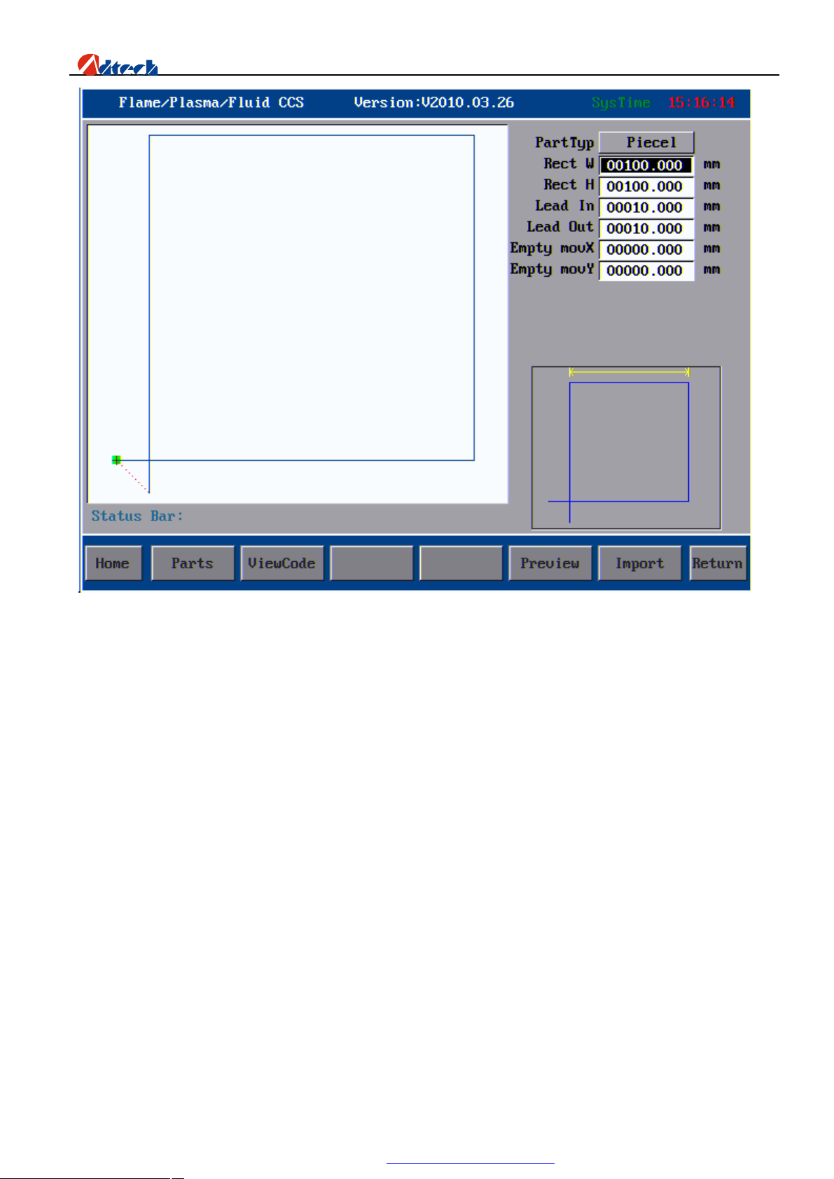
As the picture shows:
Grid line—the numbers of rectangle in every column of the grid
Grid column—the numbers of rectangle in every line of the grid
Grid width—Net width of grid (size of rectangle without gap compensation)
Lead wire length—the length of lead-in and lead-out wires; they should be the same.
Gap compensation—Grid is a special figure that needs special process, so its compensation is different from that
set in the system parameters. Here you we should set the parameters of gap compensation. The compensation in the
system parameters is invalid that if you add it with force, the system will report the error. Therefore, users could
neglect it if the system shields the compensation parameters automatically.
After the setup, press [Load figure] and the system will return to the main processing interface automatically. You
can also press [View code] to view the processing code of current figure. It is the same as figures in graphic library.
Ø File management
Show Content
38
PDF 文件使用 "pdfFactory Pro" 试用版本创建 www.fineprint.com.cn
Page 40
ADT-HC6500 Flame/Plasma/Fluid Controller
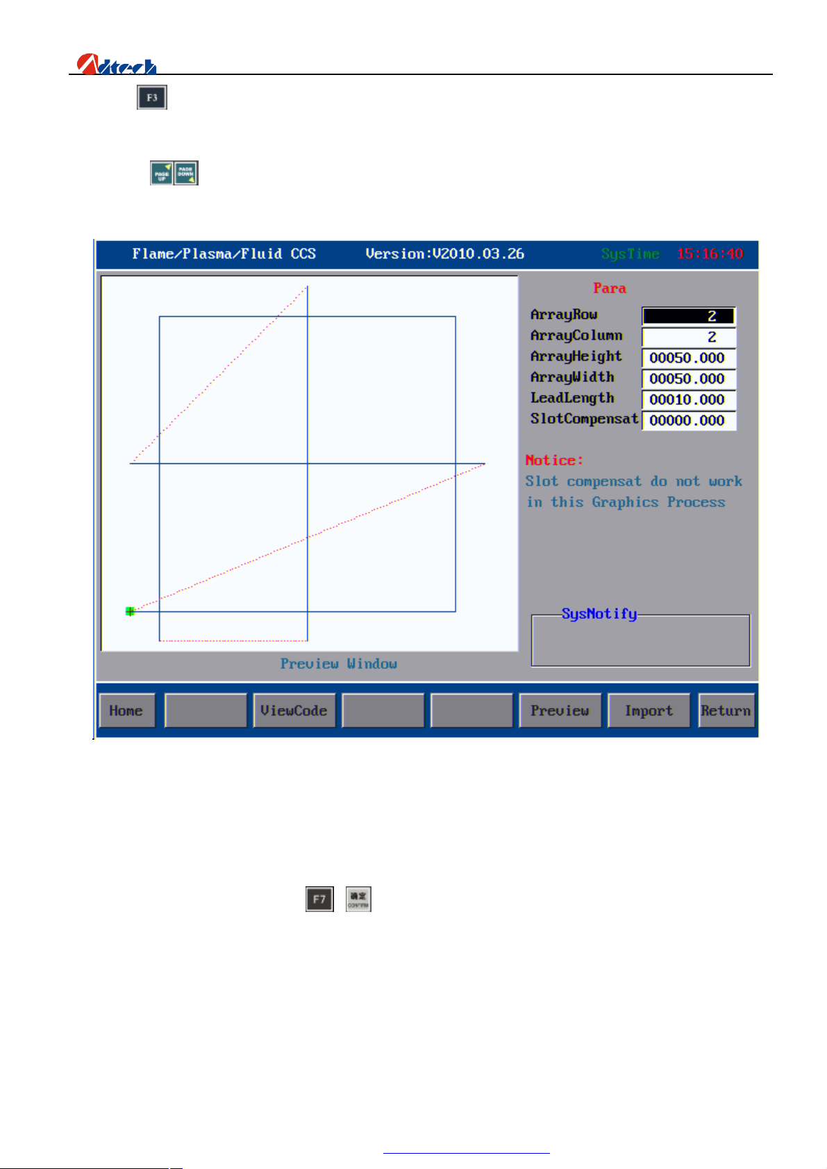
Press key in main window to enter the file management interface as follows. The left side is the preview
window for figures in current file, and the right side shows the names of processing files. If a file has several pages,
you can press to page up or down.
Interface of File Management
There is prompt info on the right bottom indicating how to operate.
Load processing: You can press or key to load the current file to processing interface and process.
Note: This key does not work when it is pressed under the catalog of folder, HD, or removable drive, for only a
file other than a folder or HD can be operated; otherwise, the system will give an error prompt.
Delete: Number key “1”; delete the current selected processing files and the entire folder;
Copy to system: Number key “2”, copy the processing files or folders to memory of controller;
39
PDF 文件使用 "pdfFactory Pro" 试用版本创建 www.fineprint.com.cn
Page 41

ADT-HC6500 Flame/Plasma/Fluid Controller
View content: You can press key to view G code of selected files, when you can test, save or modify
the code. In folder or under the HD root directory, you can press this key to go to the next lower directory.
Preview: You can press “0” to preview the selected figure with G code to see whether the figure is the part
you want to load.
Previous: You can press key to go back to previous directory until the root directory. Under the root
directory, you can carry out limited operations if you are familiar with the system. If you are not familiar, do
not add or delete any file or folder; otherwise, it will cause system crash or unexpected error, just like when you
delete system files in Drive C of your personal PC.
Copy: Number key“3”; copy the files or folder in the current interface at a fast speed
Paste: Number key “4”; paste the files or folder to the current interface.
New file
Press key in file management interface to enter new file interface as follows:
40
PDF 文件使用 "pdfFactory Pro" 试用版本创建 www.fineprint.com.cn
Page 42
ADT-HC6500 Flame/Plasma/Fluid Controller
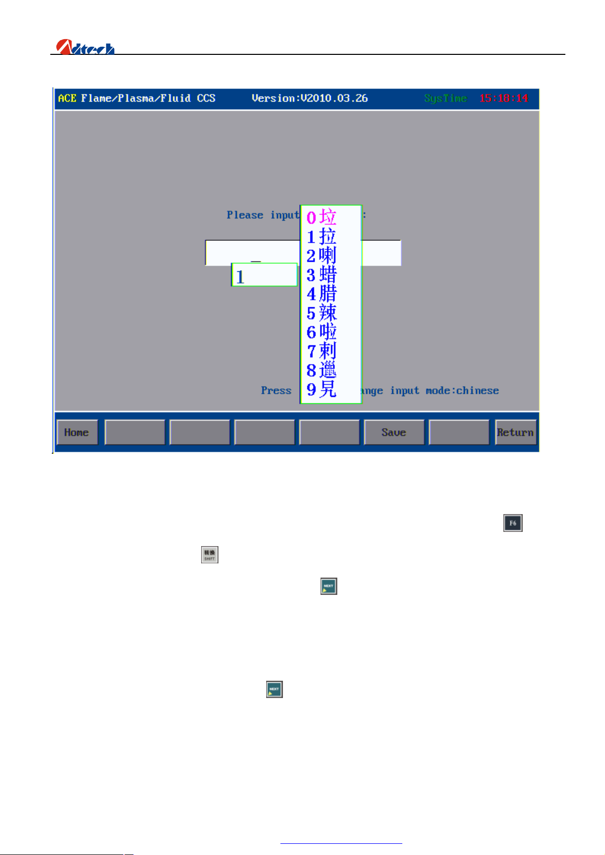
New file interface
On key panel of controller, you can press the number keys to input numbers and edit file name, press key
after the edition to save, or press key to shift the input methods between Chinese and Character, which
would be displayed on the right bottom of the screen. Press key to shift the letter on key. For example when
the top left corner shows “123”, it means you are entering the corresponding number if you press a key. If it
shows “ACE”, the letter you entered would be the first letter of the key. If it shows “BDF”, the letter you
entered would be the second letter of the key.
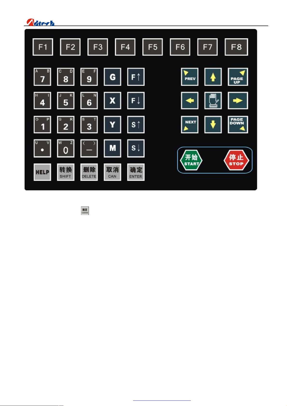
Letter is entered as the following format. Press key to shift the surrogate key. The layout is as follows:
41
PDF 文件使用 "pdfFactory Pro" 试用版本创建 www.fineprint.com.cn
Page 43
ADT-HC6500 Flame/Plasma/Fluid Controller
Keyboard layout
After the input, press key to save the file and go to the edition interface as follows. If the file name you
entered exists, the system will prompt whether to cover the original file. Carry out the operation according to
the relevant prompt.
42
PDF 文件使用 "pdfFactory Pro" 试用版本创建 www.fineprint.com.cn
Page 44
ADT-HC6500 Flame/Plasma/Fluid Controller
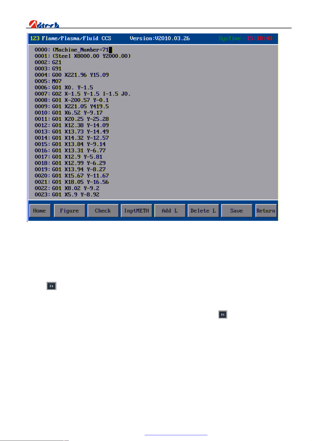
Interface of editing new file
Once a new processing file is created, you can edit the required codes of processing files in the edition area.
USB Files
Press key to perform the USB disk connection. If the USB disk is not connected well or the format of USB disk
is not compatible with system, the system will prompt “Could not find USB disk, press any key to return”. Change a
new USB disk if it is not compatible, or insert it again if it is compatible and then press key.
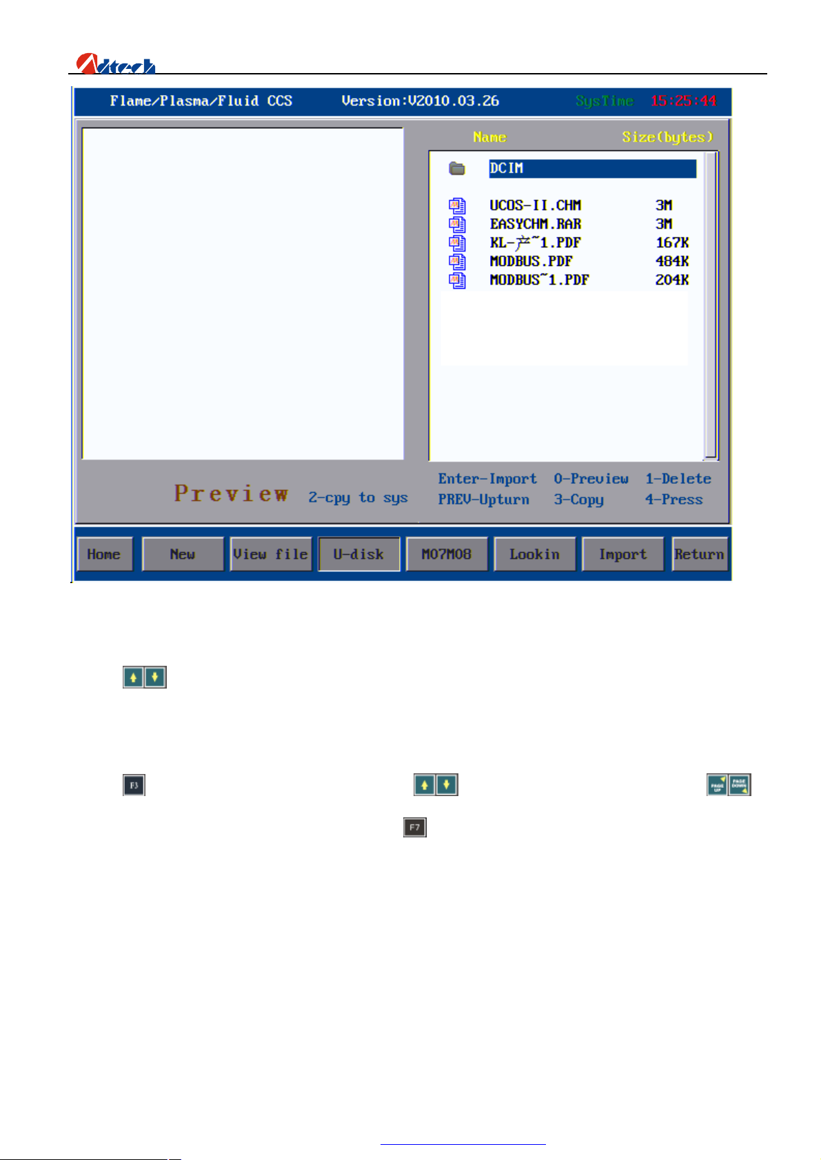
If the USB disk is connected successfully, the interface will show the names of files stored in the USB disk as
follows:
43
PDF 文件使用 "pdfFactory Pro" 试用版本创建 www.fineprint.com.cn
Page 45
ADT-HC6500 Flame/Plasma/Fluid Controller
Interface after the USB disk is connected
Press to select the processing files you want to copy, and press number key “2” to copy them to controller. A
prompt “Data copy complete, press any key to return” will pop up when the copy is complete. You can then press any
key to exit.
Press key to enter the interface of loading file, press key to switch the file within page, or press to
page up or down. When the cursor is on file name, press key to select the file.
Note: When using USB disk to download processing files for the nest software, the file should be in ANSI
format. UNICODE coding file is not recognizable.
44
PDF 文件使用 "pdfFactory Pro" 试用版本创建 www.fineprint.com.cn
Page 46
ADT-HC6500 Flame/Plasma/Fluid Controller
User-defined
This function is mainly used in device with automatic igniter. You can custom the M08 into M80 (close all output)
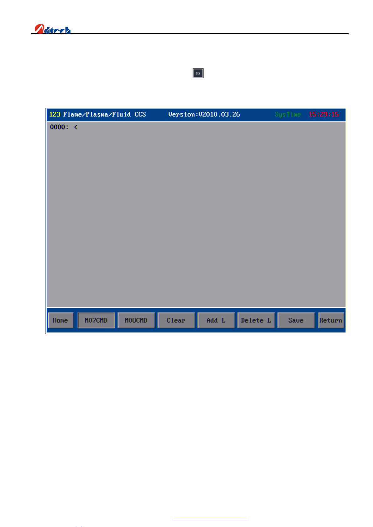
to save gas during the idle move. In edition interface, press key to enter interface for user-defining M07 and M08
as follows:
Interface of user-defined functions
1) [M07 instruction] is user-defined M07 instruction. System default M07 perforating instruction is as follows:
Flame:
① Ignition Fixed Cycle, M52
② Cutting gun falling (Fixed Cycle), M71
③ Preheating on (Fixed Cycle), M74
④ perforating cutting gun rising (Fixed Cycle), M72
⑤ Cutting oxygen on, M12
⑥ perforating cutting gun falling (Fixed Cycle), M73
Plasma:
A. With height-adjusting system:
45
PDF 文件使用 "pdfFactory Pro" 试用版本创建 www.fineprint.com.cn
Page 47

ADT-HC6500 Flame/Plasma/Fluid Controller
• Enable M22
‚ Arcing M12
ƒ Waiting for arc voltage detection signal (IN0)
After arcing, the height-adjusting control starts performing initial location (With initial location
function), perforating and perforating delay automatically, and gives a signal of successful arc voltage
detection to the controller.
B. Without height-adjusting system:
• Arcing, arcing delay M12
‚ Perforating, perforating delay
Start the following actions
Users can define the functions of M07 according to their actual demand.
2) [M08 instruction] is user-defined M08 instruction. System default M08 instruction for closing cutting oxygen is as
follows:
Flame:
①Cutting oxygen off, M13
② Cutting gun rising (Fixed Cycle), M70
Plasma:
① Close striking arc M13
② Close the height-adjusting control M23
Users can define M08 to M80 (close all output) according to their actual demand. All valves will be
closed when performing M08 to save gas.
[Clear]: Clear the data of current line.
[New line]: Add a new line below the current line.
[Delete line]: Delete the current line.
[Save]: Save the content.
Note: After you have defined M07 and M08 instructions, you should set M07 and M08 in parameter setting as
user-defined; otherwise, the instructions would not be effective.
Edit processing file
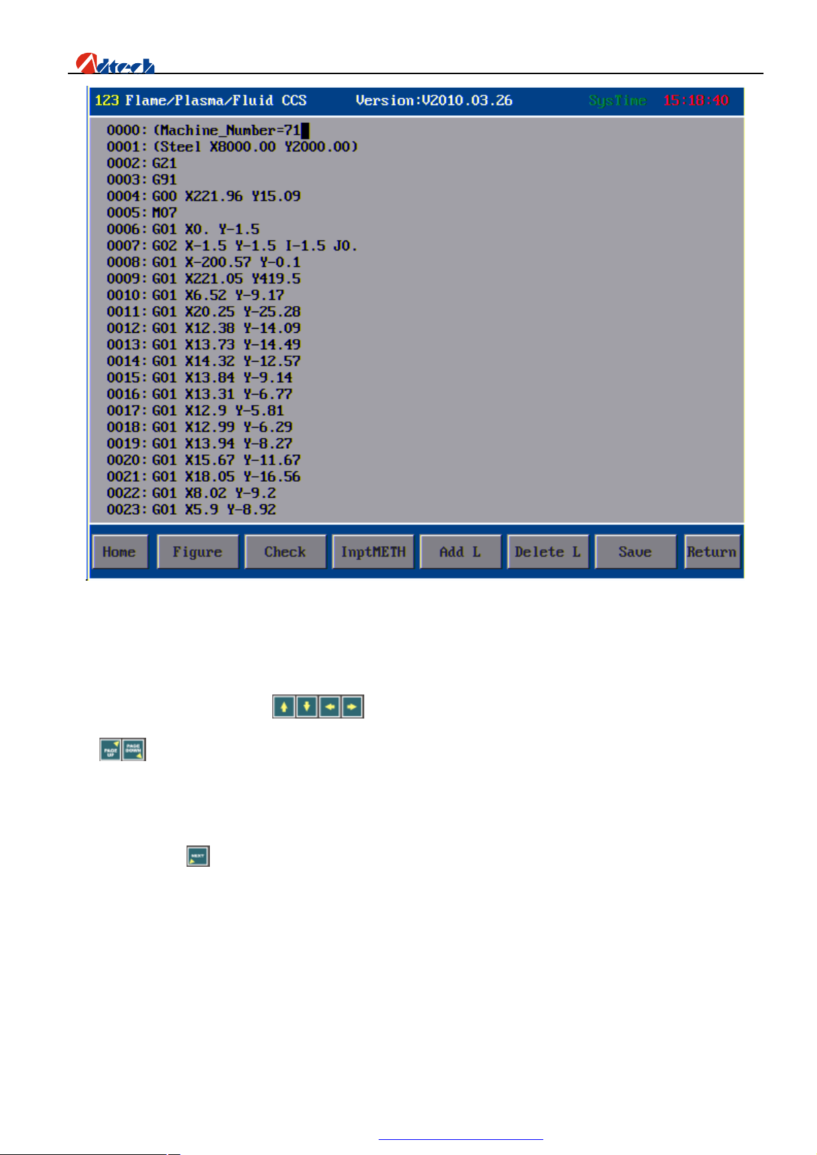
Create a new file or load a file, and enter the edition interface, you can then edit the processing file as follows:
46
PDF 文件使用 "pdfFactory Pro" 试用版本创建 www.fineprint.com.cn
Page 48
ADT-HC6500 Flame/Plasma/Fluid Controller
Interface of file content
In edition interface, you can press to move the cursor to a certain line or column within an interface, or
press to switch among pages. There are two ways to input G code in the interface, shift input and surrogate
input.
1. Shift input: Press to shift among “ACE”, “BDF”, and “ 123” input methods, which would be prompted on the top
left corner of the screen. When it shows “123”, you are entering the corresponding number if you press a key. If it
shows “ACE”, the letter you entered would be the first letter of the key, and if it shows “BDF”, the letter you
entered would be the second letter of the key. For example, if you press number key “7” when in “123” input
method, you are entering number “7” in position where the cursor located, or letter “A” when in “ACE” input
method, or letter “B” when in “BDF” input method.
47
PDF 文件使用 "pdfFactory Pro" 试用版本创建 www.fineprint.com.cn
Page 49

ADT-HC6500 Flame/Plasma/Fluid Controller
2. Surrogate input: You do not have to press key to switch the letter. You can press a key once in a certain time
interval to enter the first letter, twice to enter the second letter, or three times to enter the third letter. For example,
if you press number key “7” once in a certain time interval; you are entering number “7”. If you press this key twice
or three times in a certain time interval, you are entering letter “A” and “B” respectively.
Note: Shift input and surrogate input methods are switched in password parameter. If a key only has one letter,
you can use any input method to enter this letter.
Figure
Press key and the interface will show the preview analog figure you are editing for your reference.
Test
When you have entered codes of processing file or loaded nest software codes, you can press F3 to test whether
there is something wrong with the codes. If there is an error, the line with error will be displayed in reverse color and
a prompt will be shown at the bottom indicating the type of error. In case of error, the system will report and stop the
test; you just need to follow the instructions at the bottom of interface to figure it out.
Save
Save the modified processing file in memory of control system.
New line
During the editing, you can press or key to add a line of code under the cursor.
Delete line
During the editing, you can press key to delete the code line where the cursor is located.
Operation
1) Up/Down of Cursor: The cursor is always located at the end of a program line when it is moving up/down. It
shifts a line each time you press the key. When the cursor shifts out the first line, the screen will roll forward
a line if there is a program line ahead. When the cursor shifts out the last line, the screen will roll downward
a line if there is a program line below.
2) Page Up/Down: You can press or key to page up or down.
48
PDF 文件使用 "pdfFactory Pro" 试用版本创建 www.fineprint.com.cn
Page 50

ADT-HC6500 Flame/Plasma/Fluid Controller
3) The line number of processing program is generated automatically.
4) You can press key on panel to delete a character of the current instruction.
5) Press key to delete the current line.
Ø Part options
This section is to process the machining parts.
Figure rolling
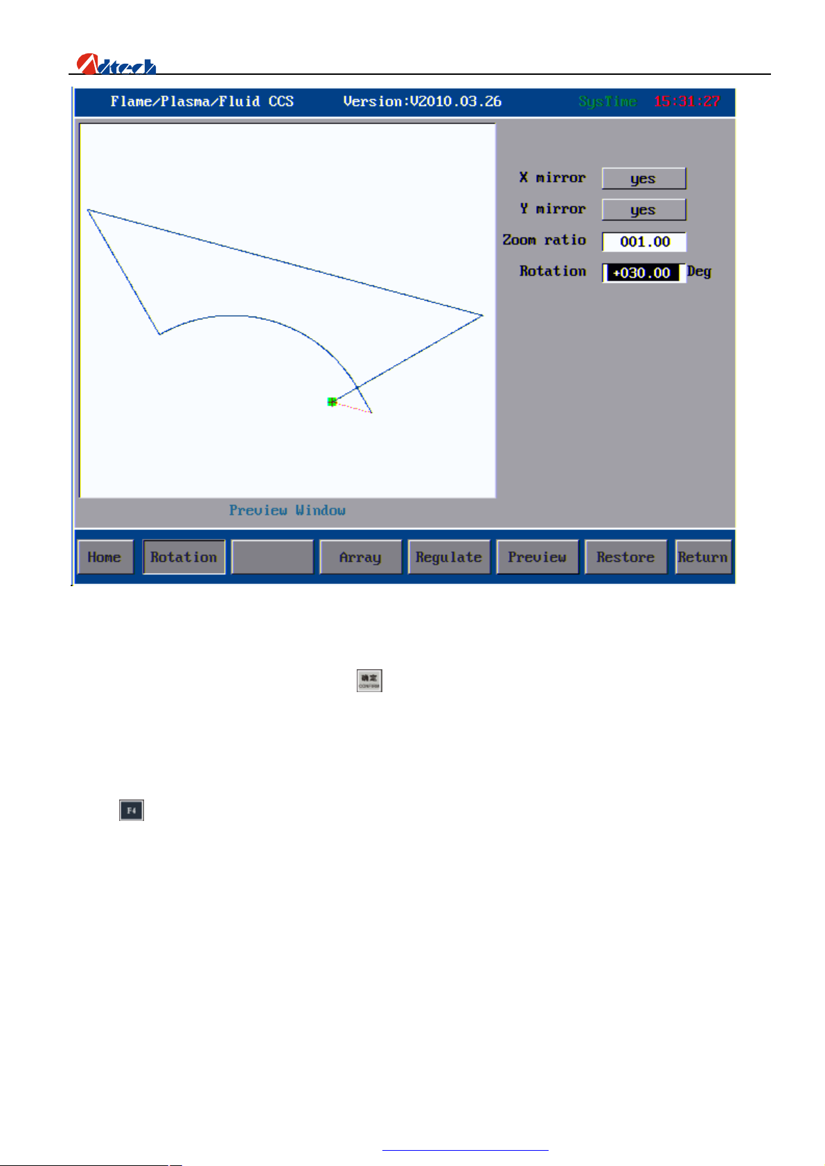
Figuring rolling functions enable you to Rotate, Mirror, and Zoom in/out the figure at the same time. Here
we are going to introduce their functions respectively.
X Mirror is to make a copy in the symmetrical direction based on Y-axis. In a similar way, Y Mirror is to
make a copy in the symmetrical direction based on X-axis, and XY Mirror is to make a copy in the symmetrical
direction based on the line 45˚ to X or Y. Rotation: It is to rotate the process figure to a certain degree
clockwise or anti-clockwise. The system default positive angle is anti-clockwise, while the negative angle is
clockwise. Zoom in/out: It is to zoom in or out the figure basing on the actual size. It is to zoom in if the value
is larger than 1, and zoom out if the value is larger than 0 but smaller than 1. Other values are invalid. For
overall interface, see picture below:
49
PDF 文件使用 "pdfFactory Pro" 试用版本创建 www.fineprint.com.cn
Page 51
ADT-HC6500 Flame/Plasma/Fluid Controller
Figuring rolling
When you have entered all parameters, press key with no mirror option selected, the figure will be mirrored,
zoomed in/out, and rotated according to the parameters. If the parameters entered are wrong or invalid, the
system will give a prompt in preview interface or restore the parts.
Figure array
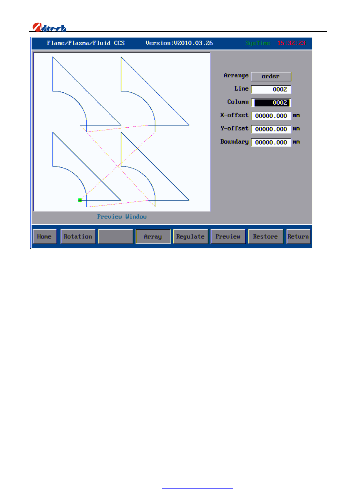
Press key to enter the figure array interface. There are two types of array, collinear array and stagger array.
For collinear array, every figure is arranged in text-align way. For stagger array, figures are arrayed in a certain
way to satisfy the demand of different processes. Array can only make some simple arrangements for figures,
which could not satisfy all requirements of customers. In this way, professional nest software is demanded.
Once you have entered the number of line, column, space, and offset according to the prompt, press [CONFIRM]
and the interface will be shown as follows:
50
PDF 文件使用 "pdfFactory Pro" 试用版本创建 www.fineprint.com.cn
Page 52
ADT-HC6500 Flame/Plasma/Fluid Controller
Interface of Figure Array
Basic operation
You have to select one of the array methods, and then enter the numbers of line and column. The limited
numbers for line and column of the software are both 9999. You can set the numbers combining your actual
processing demand and the size of part you are processing. This number is the limit value, and cannot be
achieved in practical situation.
X Off-set: It is the off-set distance between two lateral figures. If you do not input any off-set value (that
is, the off-set value is 0), the system will calculate the off-set value as the figure width (unit in MM)
automatically. If you have entered an off-set value, even 0.01MM, the system will calculate according to this
value instead of default figure width. In this situation, you have to calculate the lateral off-set value carefully to
satisfy the processing requirement of lateral distance between two figures.
Y Off-set: It is the off-set distance between two longitudinal figures. If you do not input any off-set value
(that is, the off-set value is 0), the system will calculate the off-set value as the figure height (unit in MM)
automatically. If you have entered an off-set value, even 0.01MM, the system will calculate according to this
51
PDF 文件使用 "pdfFactory Pro" 试用版本创建 www.fineprint.com.cn
Page 53
ADT-HC6500 Flame/Plasma/Fluid Controller
value instead of default figure height. In this situation, you have to calculate the longitudinal off-set value
carefully to satisfy the processing requirement of longitudinal distance between two figures.
Waste boundary value: As the name implies, it refers to the width of board you would waste during the
processing. For example during the normal processing, perforating, boundary perforating and lead-wire
operations would waste some steel boards, which is called waste boundary value. During the arraying, you
should calculate and input the value carefully to save the board to the largest extend.
We should note that figure rotating and array functions cannot be used at the same time. Array should be
done before the rotating. This operation could only be done once when you are using the resume function.
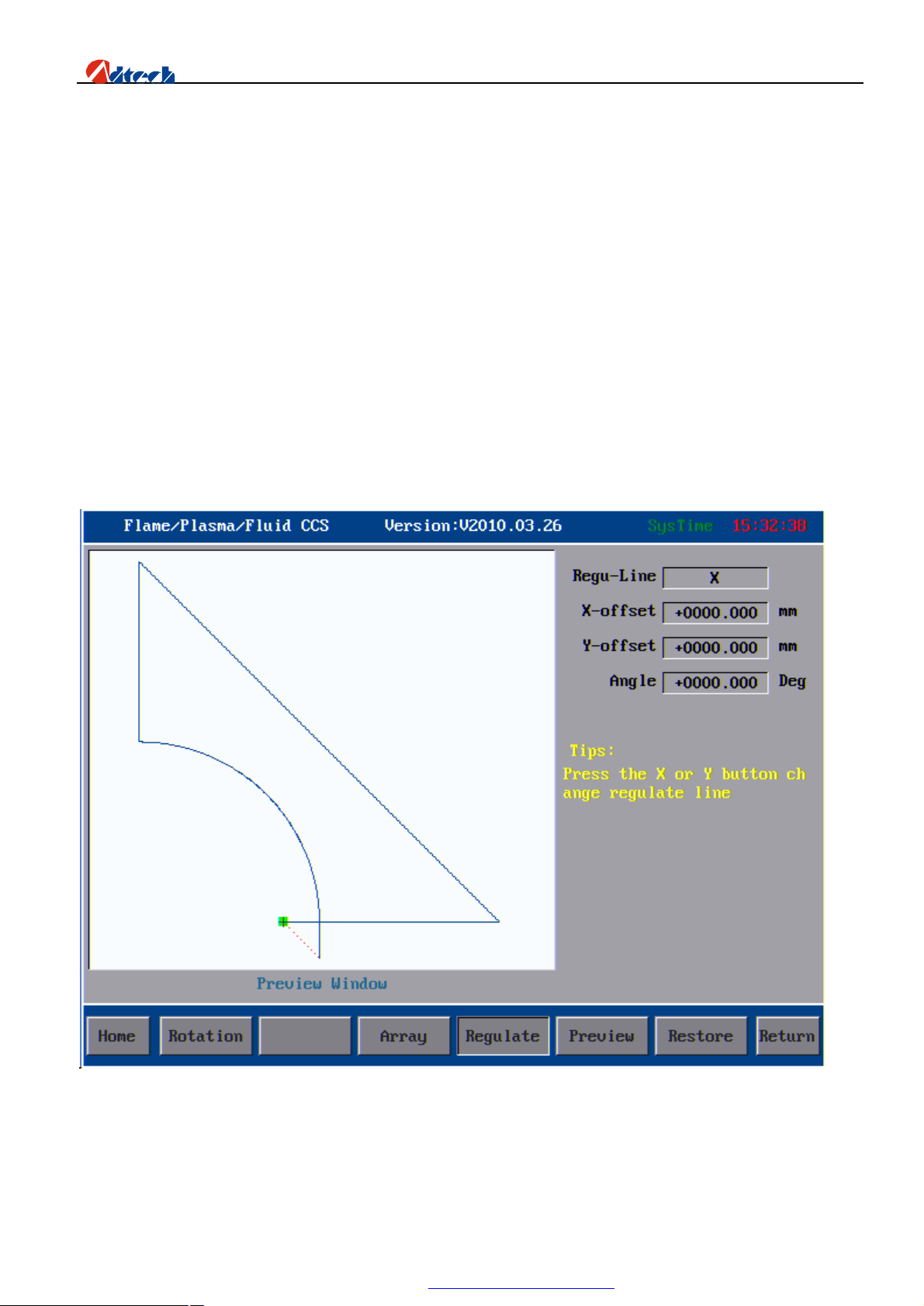
Calibration
Calibration function is to calibrate the position of figure and the steel plate to make them in a reasonable
relative position. The calibration interface is as picture below.
Calibration Interface
52
PDF 文件使用 "pdfFactory Pro" 试用版本创建 www.fineprint.com.cn
Page 54
ADT-HC6500 Flame/Plasma/Fluid Controller
A B
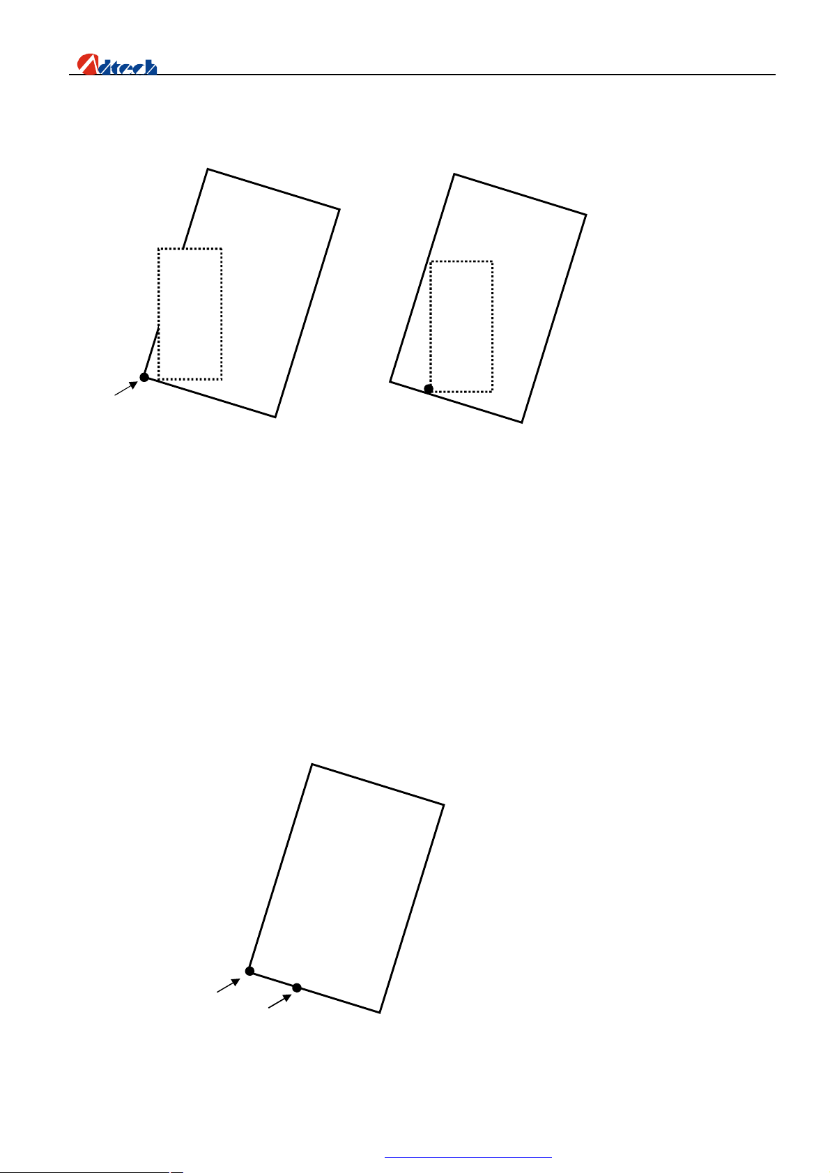
Calibration Principle:
A
Picture 1 Picture 2
1) In Picture 1, the large frame (Real line) is the steel plate, the small frame (Dashed line) is the figure to be
cut, and point A is the start point of the cutting gun. If it is cut according to Picture 1, the figure outside
may not be cut; and if it is cut when the start point is moved to the middle of the steel plate as Picture 2,
obviously it will waste the steel plate.
2) At this point, without moving the steel plate, you just have to figure out the slope angle of the plate, and
incline the figure to be processed at the corresponding angle before cutting effectively.
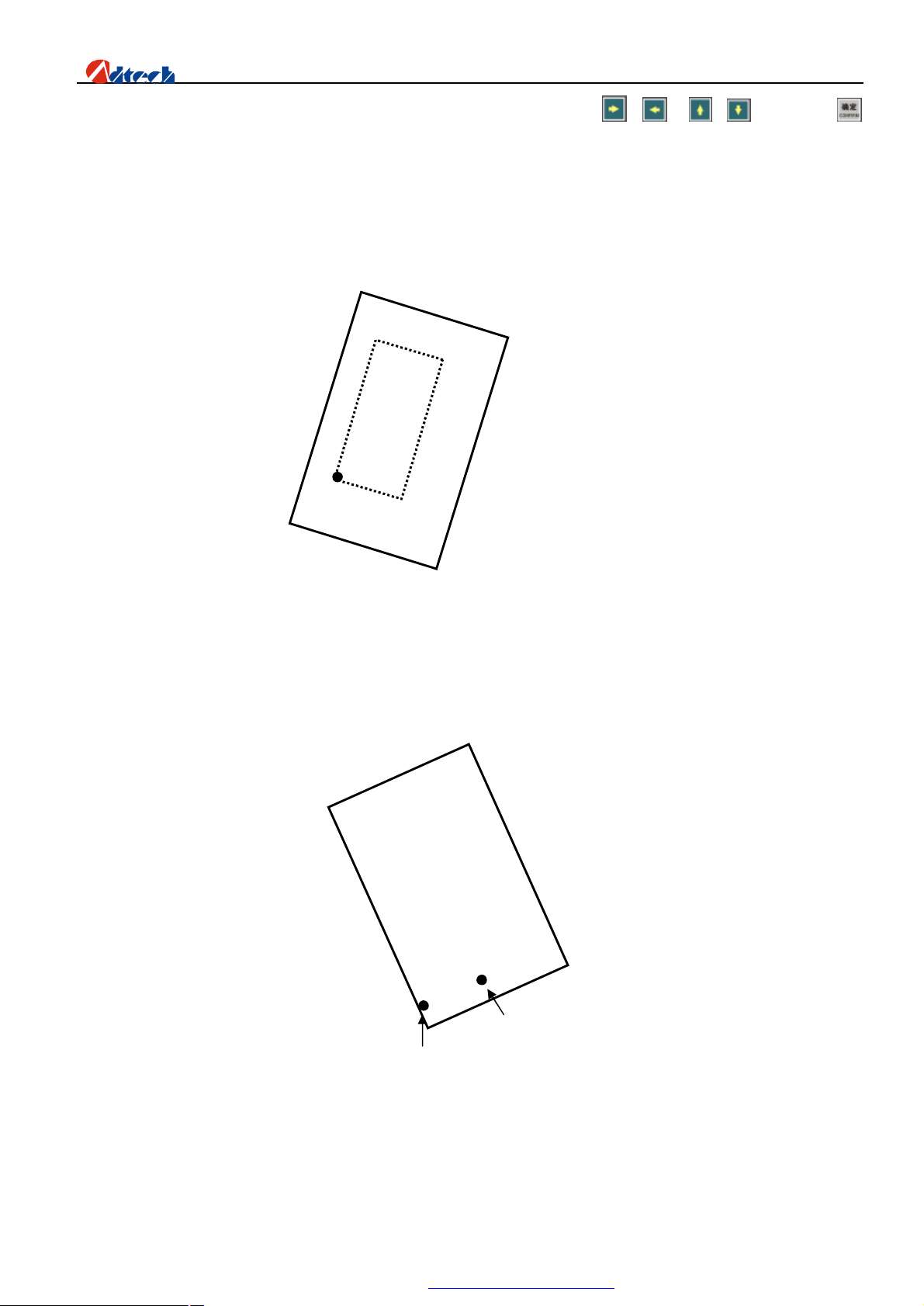
Method 1: Calibrate the reference side to X Axis
1) As above picture, point A is the start point of cutting gun. You can figure out the slope angle of the steel
53
PDF 文件使用 "pdfFactory Pro" 试用版本创建 www.fineprint.com.cn
Page 55
ADT-HC6500 Flame/Plasma/Fluid Controller
B
plate by moving the cutting gun to any point of its base line. Press → , or → ; then, press
to confirm.
2) Then, the figure displayed on the controller will be rotated at a certain degree. The position of figure to be
processed and the steel plate is shown as follows:
3) If the steel plate is inclined as follows, then, the calibration method is as below:
A
54
PDF 文件使用 "pdfFactory Pro" 试用版本创建 www.fineprint.com.cn
Page 56
ADT-HC6500 Flame/Plasma/Fluid Controller
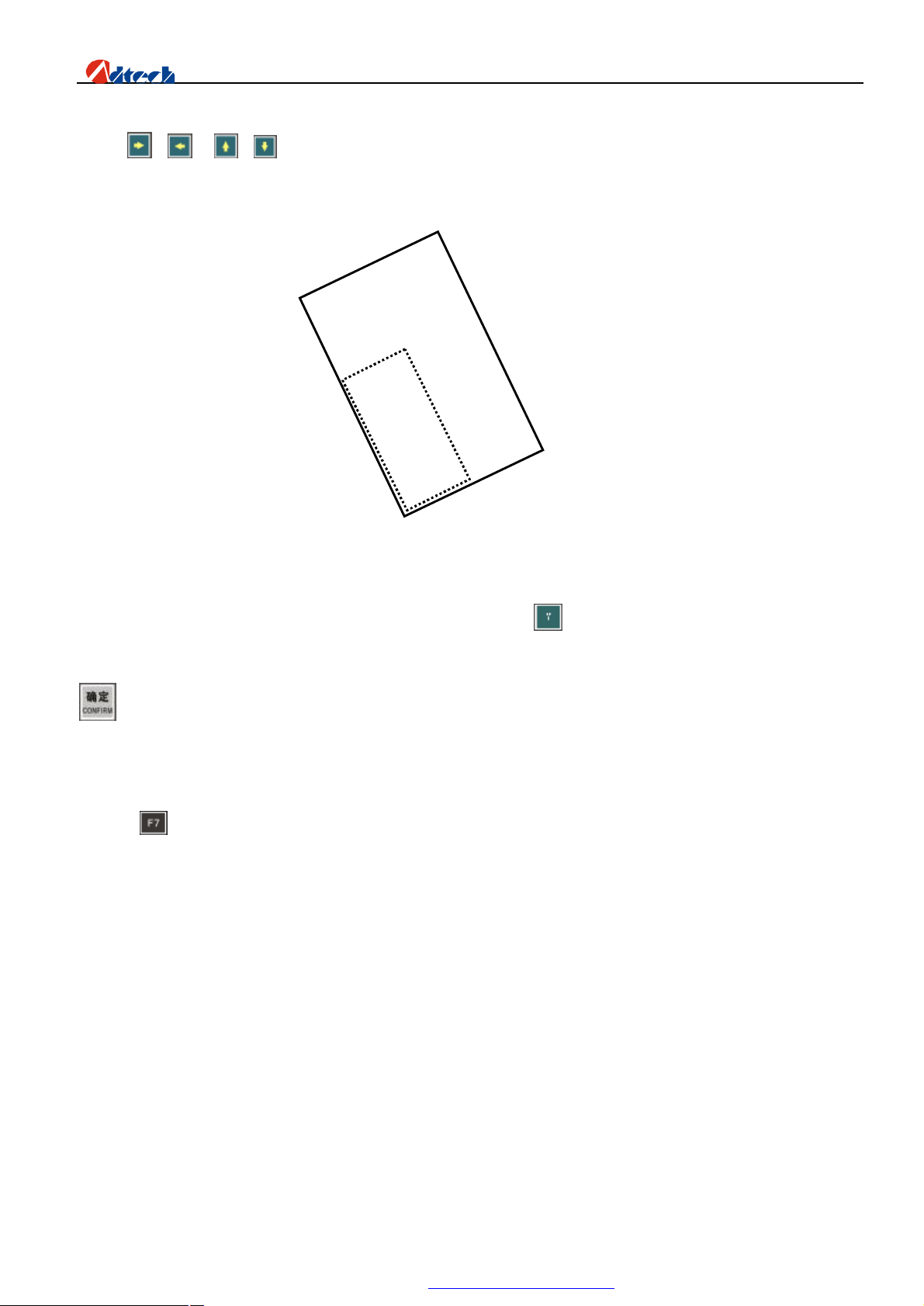
Press → , or → , then, press [OK] to confirm. The position of figure to be processed and the steel
plate is shown as follows:
Method 2: Calibrate the reference side to Y Axis
The principle is same as the method 1,only calibrate the difference axis, sometimes the steel plate is too
short for A axis, So, we can choose the Y axis to calibrate, press before you ready to calibrating, it will be
show “ Y” in the inner border. Then Make the cut gun move from A to B point same as the Method 1, press
key can be finished.
Restore
Press key to enter the restore function, and restore the current figure to original state. In this way, all
figures changed by the array or rotation will be restored to the original shape.
Note: Pay attention to the operating sequence of figure array and rotation. You cannot array the figure after
the rotation, but you can array the figure before rotation.
Ø Setup options
In main interface of parameter setup, the main system parameters are set as follows:
55
PDF 文件使用 "pdfFactory Pro" 试用版本创建 www.fineprint.com.cn
Page 57
ADT-HC6500 Flame/Plasma/Fluid Controller
Main interface of parameter setup
Ø Cutting setup
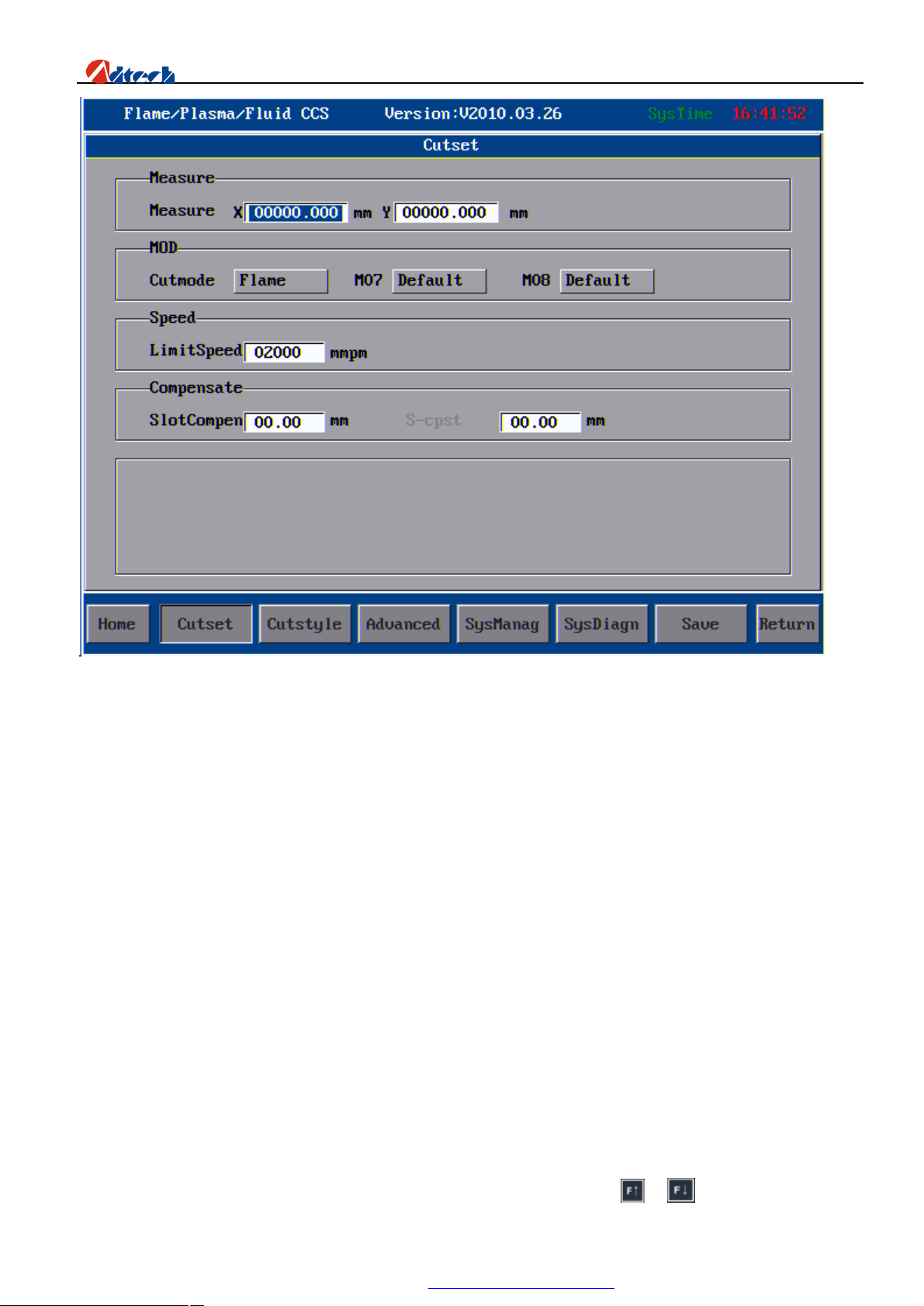
Size: It is the size of board being processed, used to check whether the board is on worktable and whether the
figure is larger than the board. This function does not work if the option is not set.
Mode: Cutting mode, M07 and M08 modes are available. Cutting mode refers to the cutting process of machine,
including flame, plasma, and preview cutting. MO7 and M08 modes are usually used by cutting torch. User-defined or
system default modes are provided. Usually, the default mode is used. For special condition, users can use their own
mode.
Note: All process parameters are saved separately according to the cutting mode to avoid mixing up. Except the
system parameters, all parameters you seen are parameters in the current cutting mode, and they do not interfere with
each other.
Speed: It is the limit speed of processing. The practical processing speed is slower than this speed, which should
multiply the speed percentage. The speed percentage can be adjusted by pressing and key in the auto interface,
56
PDF 文件使用 "pdfFactory Pro" 试用版本创建 www.fineprint.com.cn
Page 58
ADT-HC6500 Flame/Plasma/Fluid Controller
ranging between 0 and 1.
Compensation: You can set the value of cutting gap compensation and mark compensation (Not available for the
moment).
When all parameters are set, you have to save the settings. Press key, and the system will prompt “Parameters
are saved, press any key to return”, you can then press any key to save the parameters and exit.
Ø Cutting type
Two cutting processes are available at the moment, flame cutting and plasma cutting.
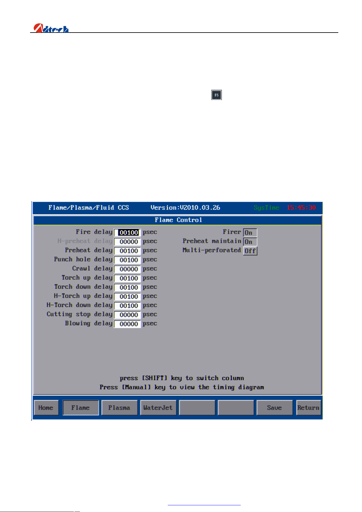
Flame cutting
Flame cutting
1. Ignition time: It is the effective time of this output signal for each ignition.
2. Low pre-heating time: For machine with low preheating function, this is to set the time of exporting
low preheating signal before the high pre-heating.
3. High pre-heating time: Set the time of exporting high pre-heating signal before each time of
57
PDF 文件使用 "pdfFactory Pro" 试用版本创建 www.fineprint.com.cn
Page 59

ADT-HC6500 Flame/Plasma/Fluid Controller
perforating. During the high pre-heating, you can press key to extend the time of pre-heating, and
press key to stop pre-heating and start processing.
4. Perforating time: set the delay time during the period after the cutting oxygen is opened and before
the cutting torch is lowered to the cutting height.
5. Creep time: set the running time of machine at creep speed after the perforating. The creep speed is
set in speed parameter interface, and displayed in the percentage of cutting speed. After the creep
time, the machine will accelerate to the set cutting speed. During the creeping, cutting surface can be
heated so that the perforating would be thorough.
6. Cutting torch rising time: set the effective time of cutting torch rising signal after each cutting
7. Cutting torch falling time: set the effective time of cutting torch falling signal before each cutting
8. Perforating cutting torch rising time: set the effective time of cutting torch rising signal during the
perforating
9. Perforating cutting torch falling time: set the effective time of cutting torch falling signal during the
perforating
10. Cutting close time: set the effective time of cutting control signal after each cutting. It is usually set
as 0.
11. Air-blowing time: set the time of sending out air-blowing signal when the cutting torch paused after
each cutting
12. Multilevel perforating: set whether the perforating mode uses the multilevel perforating mode. This
function is usually used when cutting the thick board and the system is equipped with low preheating
device. Common perforating is proper for cutting thin materials. Do not use this option if you do not
have low preheating device.
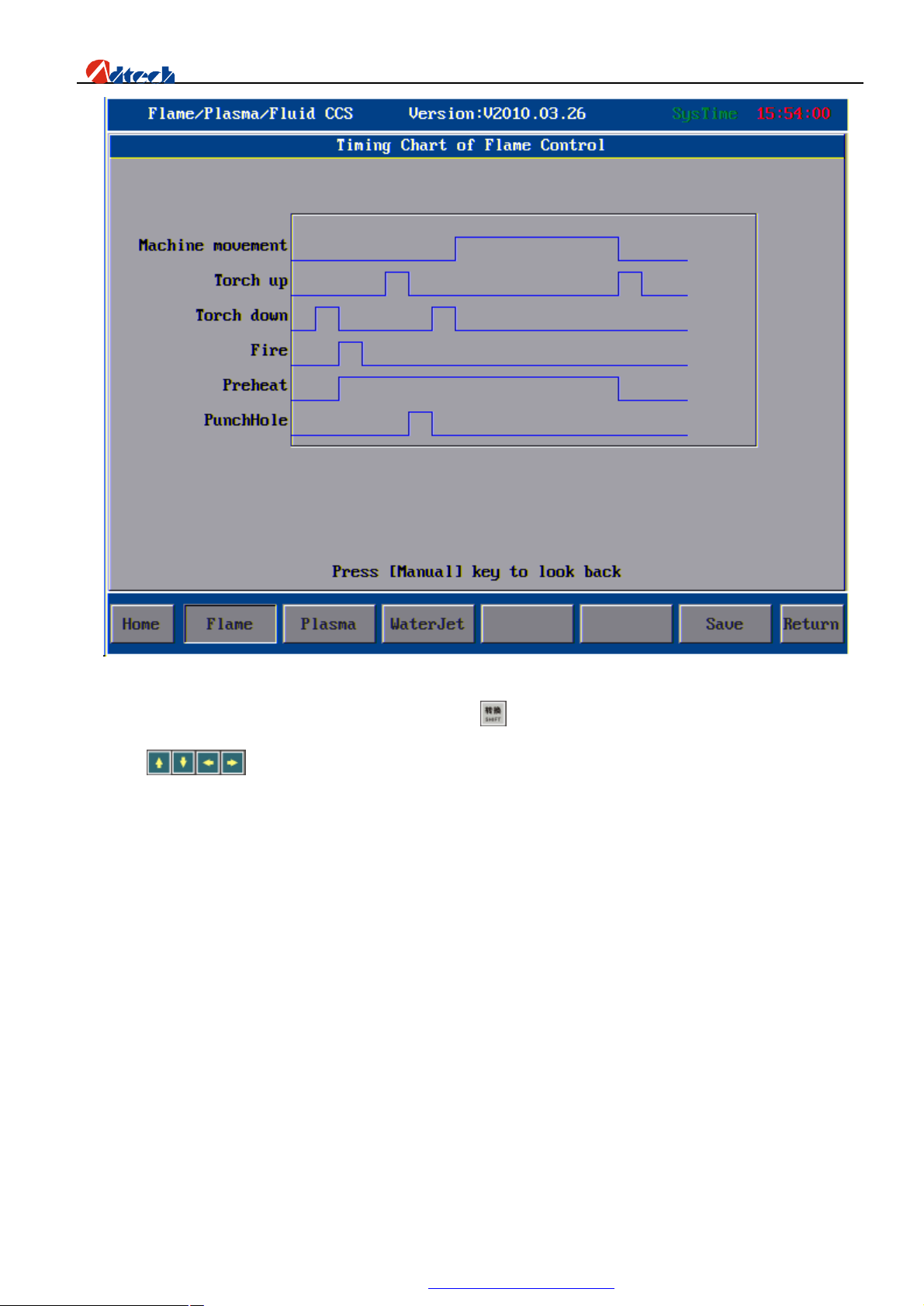
You can press key to view the sequence diagram as follows:
58
PDF 文件使用 "pdfFactory Pro" 试用版本创建 www.fineprint.com.cn
Page 60
ADT-HC6500 Flame/Plasma/Fluid Controller
Sequence Diagram of Flame Cutting
To set the parameters at the right side, you need to press key to shift the cursor to the right parameter box, and
then press to select. If a key is pressed down, it means the item is selected. After the setup, you should
save the parameters.
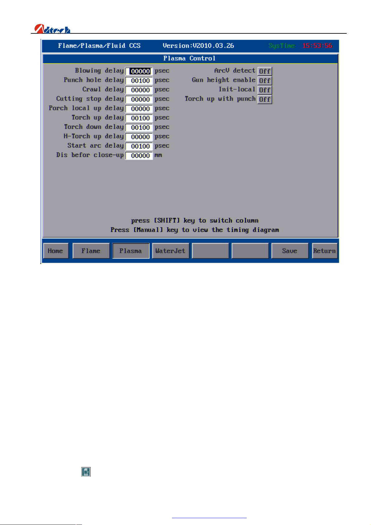
Plasma cutting
59
PDF 文件使用 "pdfFactory Pro" 试用版本创建 www.fineprint.com.cn
Page 61
ADT-HC6500 Flame/Plasma/Fluid Controller
1. Time of air-blowing: If arc feedback signal is not used, use this parameter to set the time between the
ignition of cutting torch and the operating of machine. If arc feedback signal is used, this parameter
should be set as 0.
2. Perforating time: set the time from the finish of cutting torch falling to the operating of machine,
ensuring the perforating is done perfectly
3. Creep time: set the running time of machine at creep speed after the perforating. The creep speed is set
in speed parameter interface, and displayed in the percentage of cutting speed. After the creep time,
the machine will accelerate to the set cutting speed.
4. Cutting close time: set the effective of cutting control time after each cutting, expressed in negative
number. The time for cutting control signal closed before the cutting can be set at most -1s. After the
cutting, the machine will keep cutting the arc due to the lag stop of cutting gas, which makes the
cutting route wider. In this way, this parameter is used to compensate this problem, and is usually set
as 0.
5. Cutting torch locating and rising time: set the locating and rising time during the initial locating
6. Cutting torch rising time: It is used to confirm the rising time of cutting torch. If auto height control
system is used, this parameter should be set as 0.
7. Cutting torch falling time: It is used to confirm the falling time of cutting torch. If auto height control
system is used, this parameter should be set as 0.
8. Rising time of perforating cutting torch (Not available at the moment)
9. Arcing time: set the time from the delivery of arcing signal to the end of arcing. If auto height control
system is used, this parameter should be set as 0.
10. Distance for closing height adjustment in advance: It refers to the distance for closing height
adjustment in advance when cutting a part.
11. Arc voltage detection: whether to allow the arc feedback signal symbol
12. Cutting torch height allow: For control system with auto height control, it should be set as “On”. If
there is no auto height control system or if you do not want to use it, you can set this option as “Off”.
You can press key to view the sequence diagram as picture 42:
60
PDF 文件使用 "pdfFactory Pro" 试用版本创建 www.fineprint.com.cn
Page 62
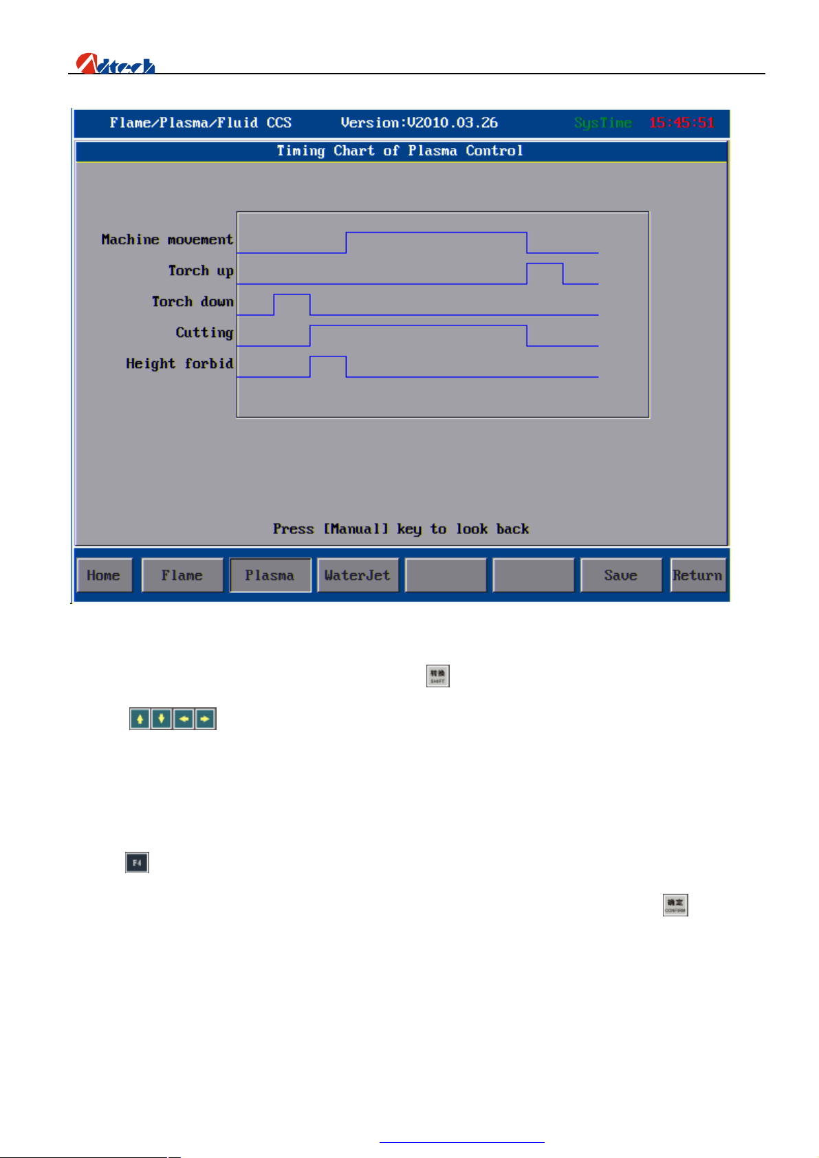
ADT-HC6500 Flame/Plasma/Fluid Controller
Sequence Diagram of Plasma Cutting
To set the parameters at the right side, you need to press key to shift the cursor to the right parameter box, and
then press to select. If a key is pressed down, it means the item is selected. After the setup, you should
save the parameters.
Ø Advanced setup
Press in main parameter interface, and input the password “360” or “361”. Parameters in this interface are not
modified usually, so you have to input password to get in. If you enter the correct password and press key, you will
enter an interface as follows:
61
PDF 文件使用 "pdfFactory Pro" 试用版本创建 www.fineprint.com.cn
Page 63
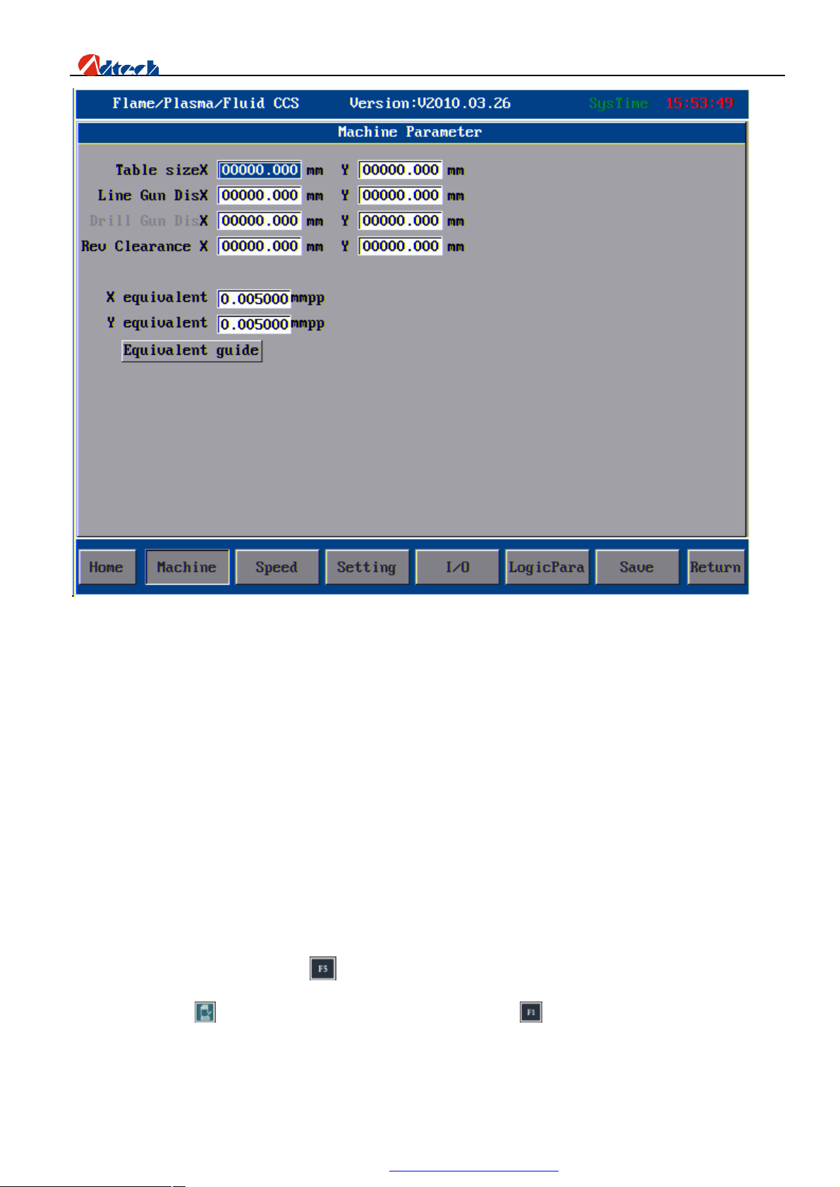
ADT-HC6500 Flame/Plasma/Fluid Controller
Interface after you have entered the correct password
Machine setup
1. Worktable size: Set the worktable size of the machine, so that the system will prompt whether the board
or figure exceeds the allowable size of worktable. For system without worktable, it can be set as 0.
2. Scriber distance: Set the distance between scriber and cutting gun. (This function is not available for the
moment)
3. Backlash: Set the backlash compensation of X axis and Y axis.
4. Pulse impulse equivalent: Set the pulse equivalent. The pulse equivalent is a bridge for the system to
communicate with outside. It should be tested for several times to ensure the accuracy. To set the pulse
equivalent, manual and wizard methods are available
1. Manual setup
1) Set the X and Y pulse equivalent as 0.010000 (The control system sends out a pulse, and the motor
moves 0.01MM), then press to save and exit to the main interface.
2) Press to enter the interface of manual mode, and press key to set the moving distance of X axis,
and input your desired inching length. Suppose the unit of inching is 1000MM.
62
PDF 文件使用 "pdfFactory Pro" 试用版本创建 www.fineprint.com.cn
Page 64
ADT-HC6500 Flame/Plasma/Fluid Controller
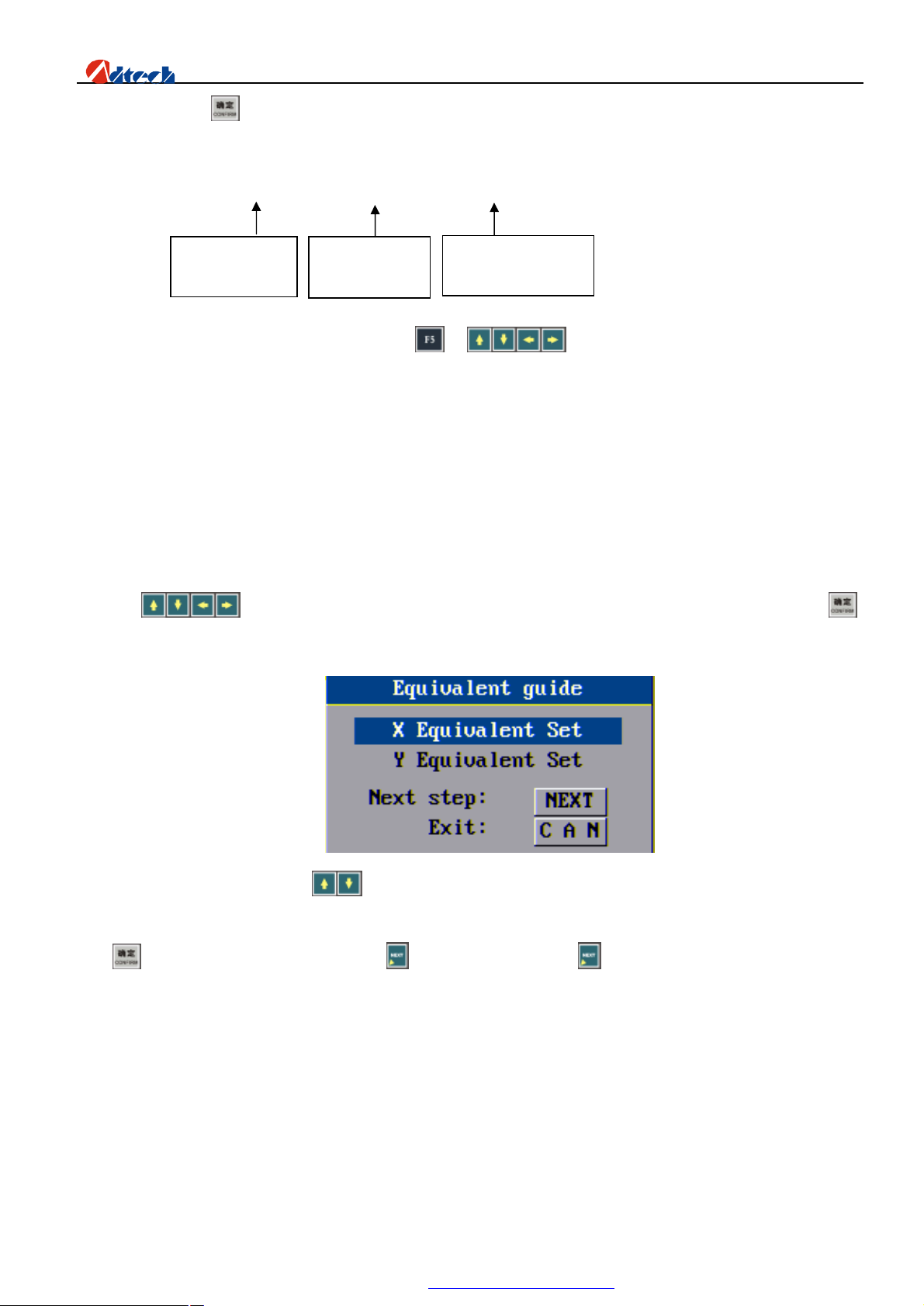
3) Press key to start inching. Suppose the actual moving distance is 978MM.
The calculation formula is as follows:
4) 978 ÷ ( 1000 ÷ 0.01 ) = 978÷100000 = 0.009780
Actual moving
distance
Actual inching
distance
Pulse equivalent of
current system
5) Back to the main interface, press and key to move the cursor to set the accuracy.
Input 0.009780 as the pulse equivalent of X and Y axes.
Note: Usually, there will be a minor error between the pulse equivalent of X and Y of the same device;
therefore, they should be set respectively during the test. (It is recommended to set the pulse equivalent as the
same value.)
2. Setup wizard of system pulse equivalent
The application and operations of pulse equivalent setup wizard are as follows:
Press key in parameter interface to move the cursor to pulse equivalent setup wizard, and press ,
an interface is shown:
In this interface, you can press key to set the pulse equivalent of X and Y axes respectively. Here we take
“X-axis pulse equivalent setup” as an example. When the cursor is on “X-axis pulse equivalent setup”, if you
press key, the setup will be cancelled. Press to continue and then press , an interface as follows pops up:
63
PDF 文件使用 "pdfFactory Pro" 试用版本创建 ÿ www.fineprint.com.cn
Page 65
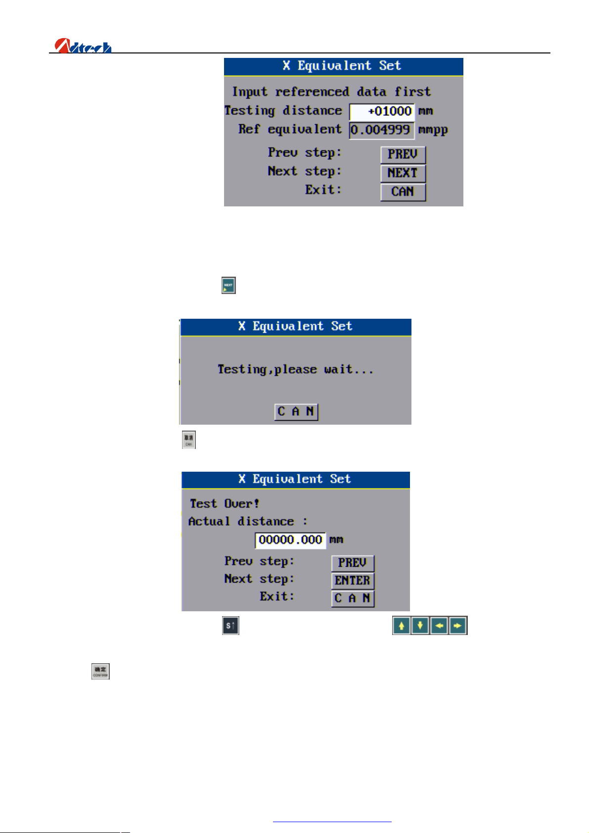
ADT-HC6500 Flame/Plasma/Fluid Controller
Here we take the default value. However, “Set the moving distance of X axis” should be set matching the practical
worktable. The cutting torch should not be shifted out the worktable or touch other parts. If you do not use the default
1000mm, you can set the proper length as you like by just pressing the number keys. To delete, you can just press the
Delete key directly. After the setup, press key and the system will start processing as the following picture shown:
At this point, you can press to cancel and reserve the original pulse equivalent.
When the test is complete, you can press key to lift the cutting torch and press to move it away for
the convenience of measuring the moving distance with calipers. Then, Input the measured data into the prompt box
and press key, the system will prompt the pulse equivalent setup is complete. As the picture shown:
64
PDF 文件使用 "pdfFactory Pro" 试用版本创建 www.fineprint.com.cn
Page 66
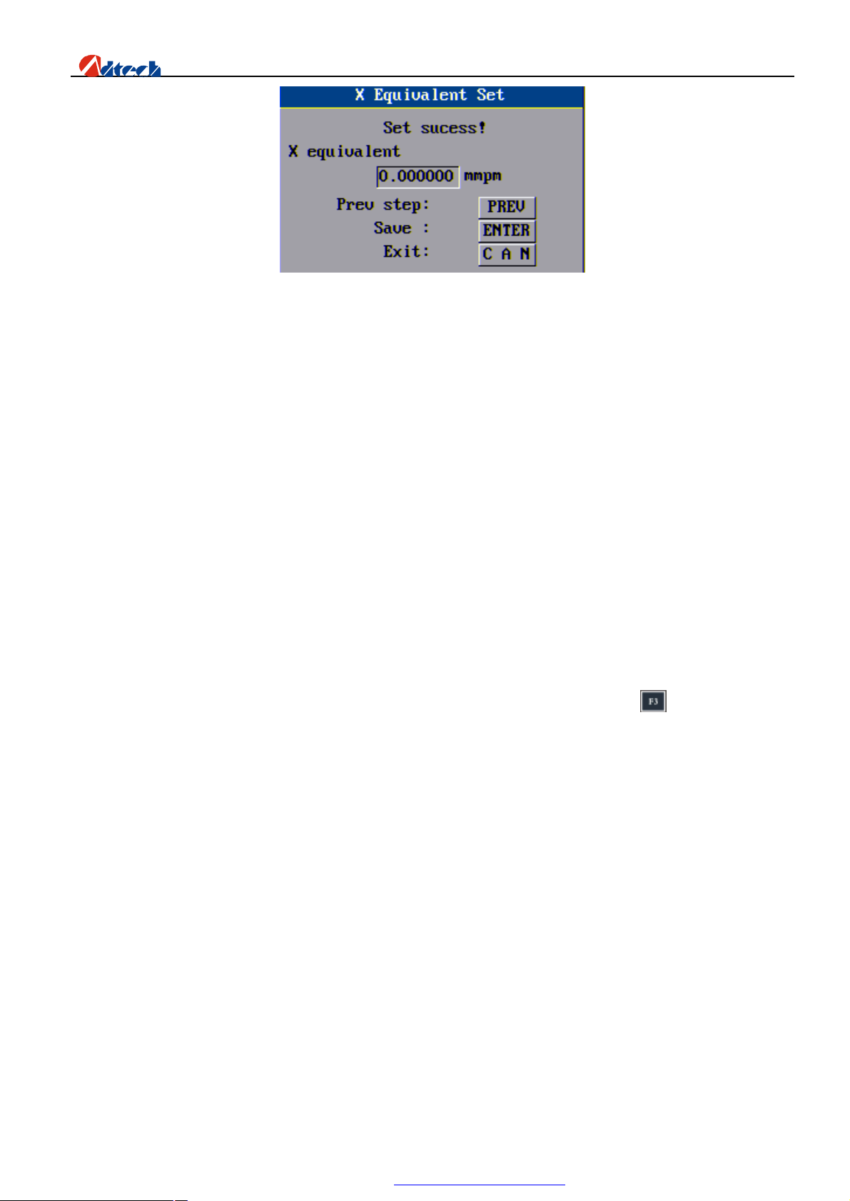
ADT-HC6500 Flame/Plasma/Fluid Controller
Press confirm key to complete, and the value of pulse equivalent will be displayed in the pulse equivalent column
automatically. You can set the pulse equivalent of Y axis with the same method.
Note: Usually, there will be a minor error between the impulse equivalent of X and Y of the same device; therefore,
they should be set respectively during the test. (It is recommended to set the pulse equivalent as the same value.)
Speed parameter
1. Start-up speed: Set the speed of cutting torch at the beginning of start-up.
2. Acceleration of 1st section: Acceleration of the 1st section usually set when linear acceleration is adopted.
3. Speed of 1st section: Set to accelerate to the 1st speed point, usually set with the acceleration of 1st section
(Not available at the moment)
4. Acceleration of 2nd section: Set the acceleration of 2nd section, and the speed of 1st section is taken as the
start-up speed of 2nd section. (Not available at the moment)
5. Processing speed limit: Set the maximum speed during the processing. The practical speed equals to the
result of this speed limit multiplying the speed percentage.
6. Manual speed limit: Set the maximum speed of machine in manual operation. The practical speed equals
to the result of this speed limit multiplying the speed percentage.
7. High/Medium/Low speed: You can select different speed when you press (Shift speed) in the
interface of manual operation.
8. Minimum corner speed: It is usually set as 0.
9. Fast/Slow back-to-zero speed: Return back to zero in fast speed first until it stops when touching the
switch, and then leave in reverse direction in slow back-to-zero speed until the signal disappears. This is
different from back to origin.
10. Creep speed: The machine needs to move forward slowly when perforating, which is called creep. The
speed, expressed in speed percentage and determined by this parameter, is used in this situation.
11. Plasma HI/LO speed: This parameter is to define a speed limit. When the cutting speed is reduced to be
lower than this limit speed, an inhibiting signal on the height of cutting torch is exported. When the
cutting speed is higher than this limit speed, a permit signal is exported.
12. Plasma in/out-corner distance: It defines a distance range, in which, when you are not using cutting gap,
the machine will export height prohibit and height permit signal. Just set it as default 0.
Interface of speed parameter is shown as follows:
65
PDF 文件使用 "pdfFactory Pro" 试用版本创建 www.fineprint.com.cn
Page 67
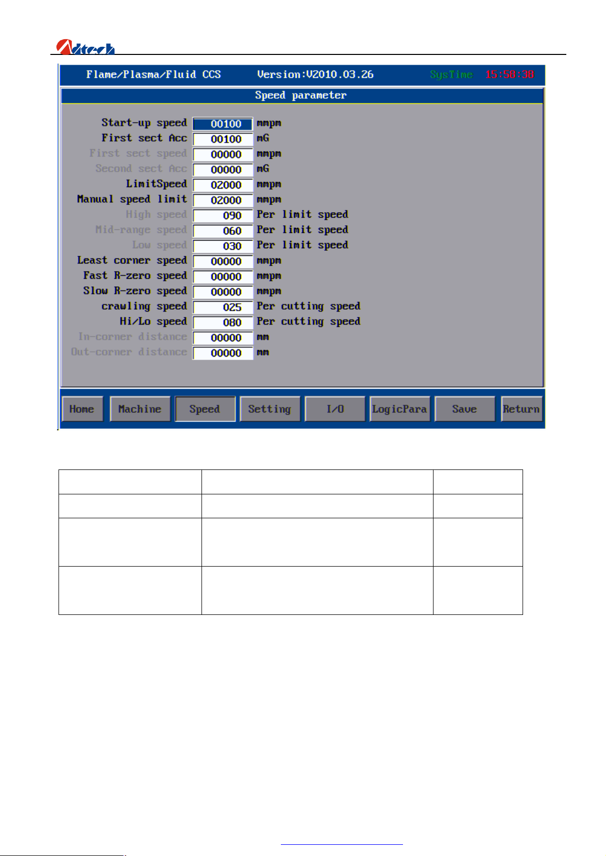
ADT-HC6500 Flame/Plasma/Fluid Controller
Interface of speed parameter
Parameter Explanation Unit
Start-up speed Start-up speed of X/Y axis Mm/Minute
Acceleration of 1st section The value of each added speed from start-up
Mm/Minute
speed to the maximum speed of X/Y axis
Manual speed The speed of X/Y axis, G00 and returning
Mm/Minute
speed in manual run
Note:
In practical cutting, you need to perform acceleration/deceleration operations at the corner. Too fast an
acceleration/deceleration at the corner would lead to halfway cutting or flame-out, and too slow the speed may
not form a right angle at the corner or lead to circular arc. In this way, the “start-up speed” and “acceleration”
in “ Speed” setup should be set for several times according to the current pulse equivalent to the optimum state.
Reference value:
66
PDF 文件使用 "pdfFactory Pro" 试用版本创建 www.fineprint.com.cn
Page 68
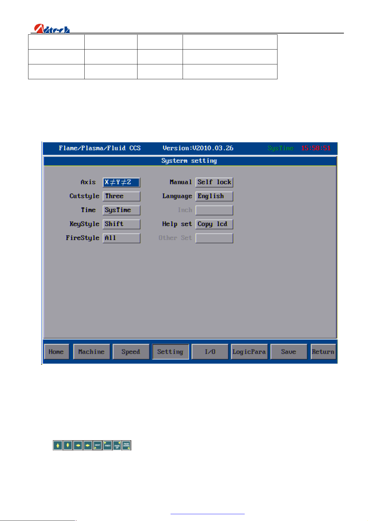
ADT-HC6500 Flame/Plasma/Fluid Controller
Processing speed Pulse equivalent Start-up speed Acceleration
500mm/Minute 0.008000 300 80-100 (Adjusted with emphases)
500 mm/Minute 0.001000 300 5-15 (Adjusted with emphases)
Note: In auto cutting, the processing speed is allowed to be slower than the start-up speed. However, in auto mode, if
the processing speed is slower than start-up speed, the system will be run at start-up speed.
System setup
Other settings, including the settings on system control, are as follows:
Interface of other settings
1. On-axis setup: Set the on-axis function of the motor. This function can be enabled when using two motors to
control an axis. “Non on-axis” means X-axis and Y-axis are controlled by a motor respectively. “XZ bonding”
means that X axis is controlled by two motors and the other motor of X axis is controlled by Z-axis output.
“YZ bonding” means that Y axis is controlled by two motors and the other motor of Y axis is controlled by
Z-axis output.
2. Manual setup: Set the manner of moving cutting torch in manual mode. “Auto-lock” means that as you press
in the manual mode interface, the cutting torch will start moving at eight
directions, and still when you release your hands until you press these direction keys again or the stop key.
“Inching” means that as you press these eight keys, the cutting torch will start moving at eight directions and
67
PDF 文件使用 "pdfFactory Pro" 试用版本创建 www.fineprint.com.cn
Page 69
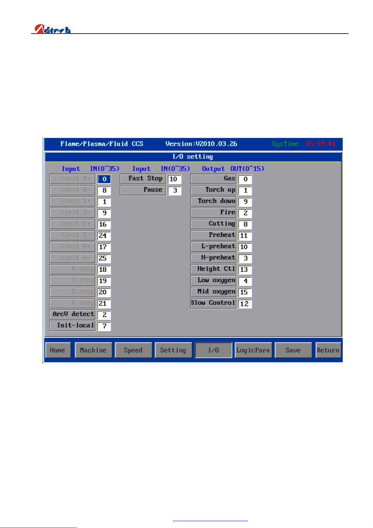
ADT-HC6500 Flame/Plasma/Fluid Controller
stop as you release your hands.
3. Number of cutting type: It refers to the types of cutting available. Three options are provided. “1” means only
one type, “Flame”; “2” means two cutting types, “Flame” and “Plasma”, are available; “3” means three cutting
types, “Flame”, “Plasma” and “Preview”, are available.
4. Language: Set the language of cutting system. To change the language, you just need to put the relevant
translated files in “\LAN” folder of the system, and then set the corresponding language here. (Not available at
the moment)
5. Input mode: Shift input or surrogate input is available. It is recommended to use the shift input.
I/O setup
I/O setup allows you to set the input and output of the system on the condition that they should match the
peripheral interface of cutting machine. The marked numerical symbols is not the line number (socket number)
but the IN and OUT numbers. For the relationship between line number and OUT/IN number, please refer to the
hardware user manual. At present, system supporting input 36 ports, output 16 ports. System will remind in the
look down Right if the ports setting exceed the range. After the modification, you can press [Save] to save the
setup and use the interface you have modified. This function is provided for the convenience of future
maintenance. If an interface is broken, you can just make a correction here rather than sending it back for
maintenance.
Note: To avoid mix-up due to the lack of understanding on cutting machine, it is suggested not to modify
the interface if there is no broken interface; otherwise. You can change the setup as you like if you are
familiar with the cutting machine.
68
PDF 文件使用 "pdfFactory Pro" 试用版本创建 www.fineprint.com.cn
Page 70
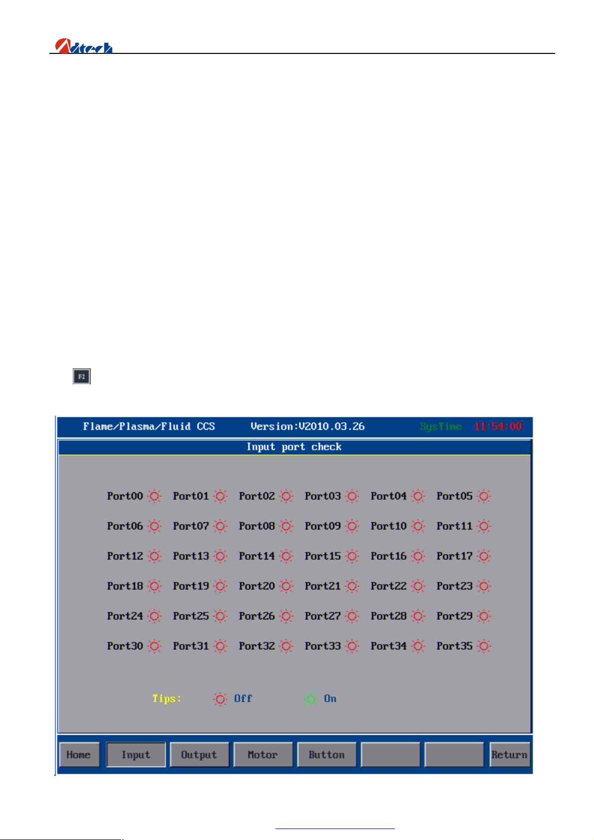
ADT-HC6500 Flame/Plasma/Fluid Controller
Logic parameter
Machine limit, logic level and effective signal are set here. You can use them following the instructions:
Whether X-axis STOP0 signal is effective: When the cutting machine receives STOP0 signal, it will give out a
hardware stop signal if the STOP0 signal is effective. If this signal is not applicable, set this option as 0. This is
also applicable to the YZA axes.
Logic level stopped by X-axis: 0—Low level stops, it is high level in normal condition; 1—high level stops, it
is low level in normal condition. This is also applicable to the YZA axes.
Whether X-axis limit is effective: 0—effective, 1—ineffective; this is also applicable to the YZA axes
Logic level of X-axis limit: It refers to the logic level of limit. 0—low level effective, 1—high level. This is also
applicable to the YZA axes.
I/O effective logic level: It refers to the I/O level of normal I/O port (IN, OUT number). 0—low level effective,
1—high level effective.
Ø System Diagnosis
Interface introduction
Press key to enter the interface of port diagnosis to test the input ports. Red light: Disconnected. Green light: Closed.
System will show the port No. simultaneously. As shown below:
69
PDF 文件使用 "pdfFactory Pro" 试用版本创建 www.fineprint.com.cn
Page 71
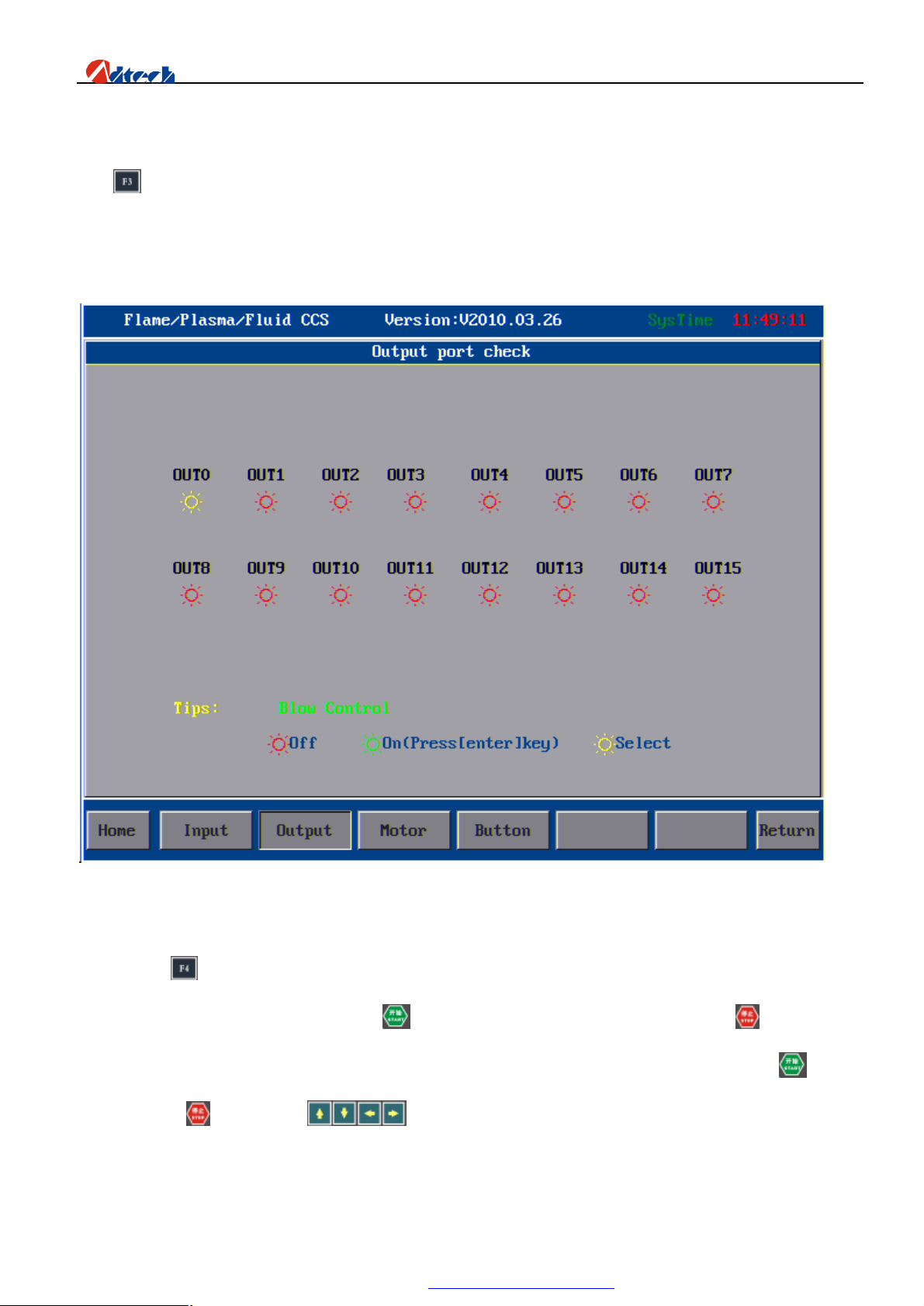
ADT-HC6500 Flame/Plasma/Fluid Controller
Interface of input port diagnosis
Press key to enter the interface of output port diagnosis to test the output ports. Red light: Disconnected; Yellow
light: Selected; Green light: Closed. System will show the port No. simultaneously, when you choose the ports.
(Correspond with I/O setup on the front)
Interface of output port diagnosis
You can press key to enter the interface of motor control diagnosis. Yellow words with orange lake bottom indicate
that the direction of this axis is selected. Press key and the motor will start to run. You can press key any time to
stop the motor. As the following picture shows, the x-axis will be rotated in positive direction if you press key, and
stop if you press . You can press keys to switch the direction of different axes.
70
PDF 文件使用 "pdfFactory Pro" 试用版本创建 www.fineprint.com.cn
Page 72
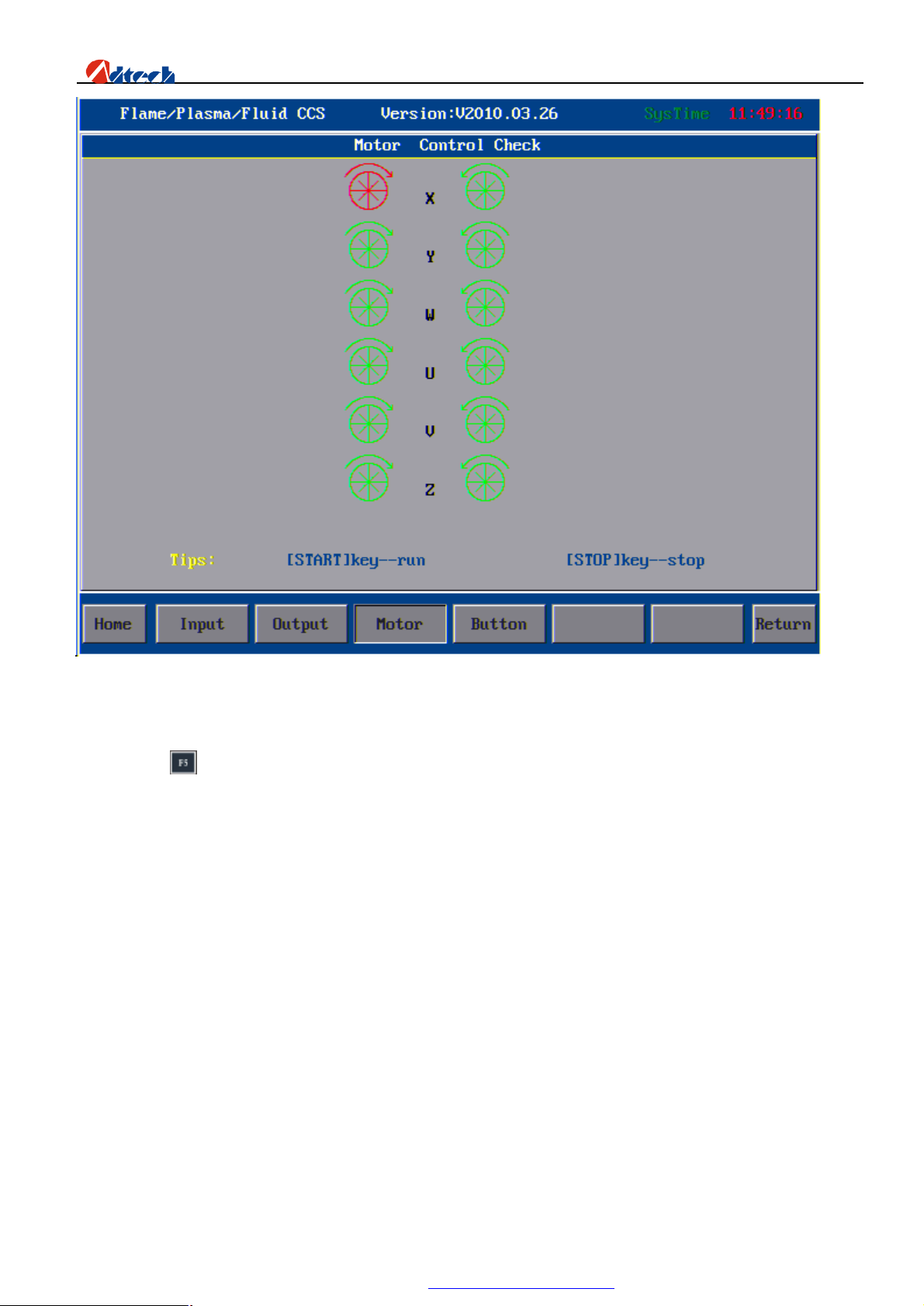
ADT-HC6500 Flame/Plasma/Fluid Controller
Interface of motor control diagnosis
You can press key to enter the key test interface. The corresponding key will have an action and become the state of
being pressed if you press a key. If there is no response when you have pressed a key for several times, it means the key
is out of order.
71
PDF 文件使用 "pdfFactory Pro" 试用版本创建 www.fineprint.com.cn
Page 73
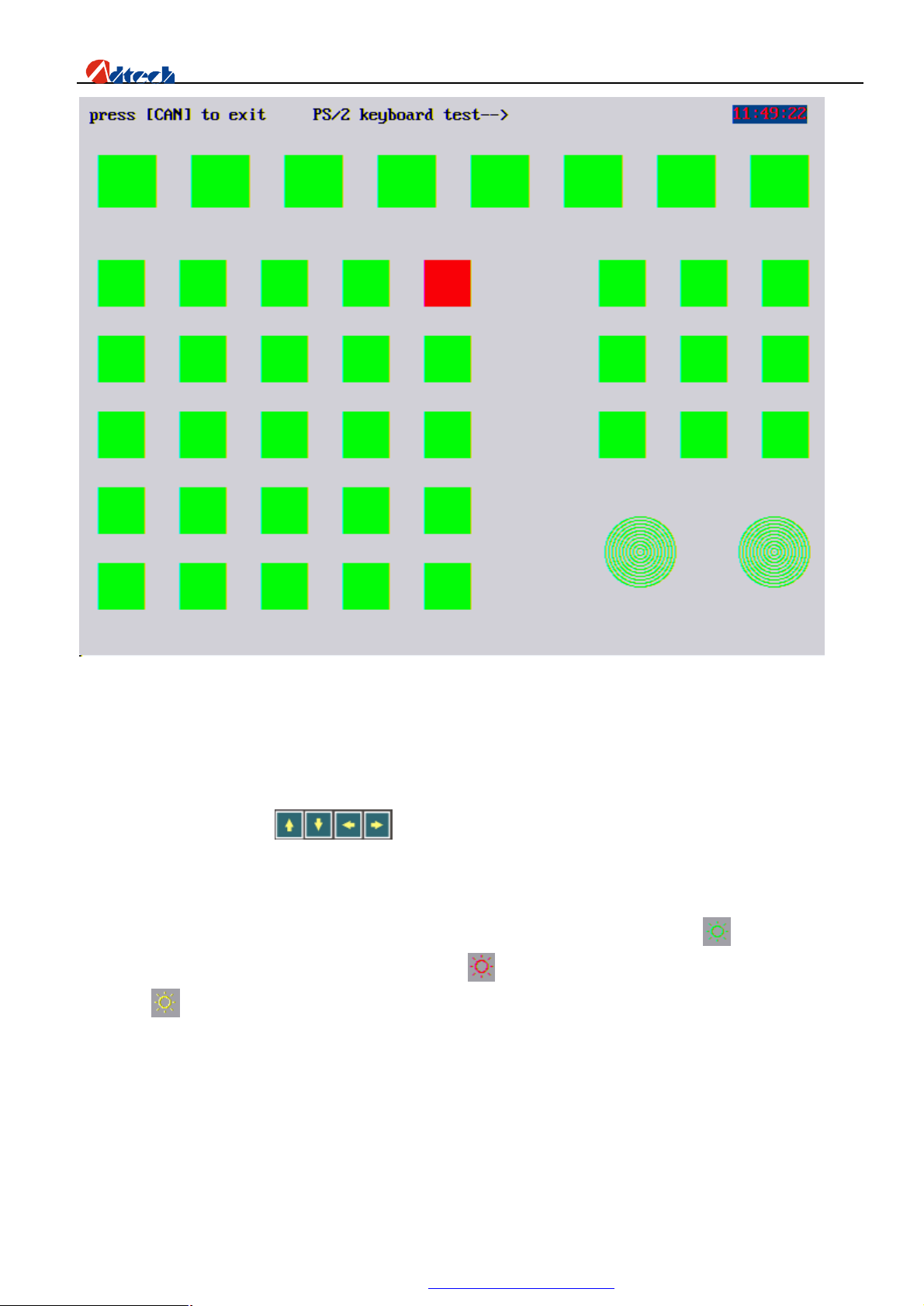
ADT-HC6500 Flame/Plasma/Fluid Controller
Key test interface
Basic operation
The system diagnosis shows the open hardware resource of the system. In system diagnosis window, you can
check the following interfaces:
1) Output check: Press key to move the cursor to any position of the 16 photovoltaic isolation
outputs, and press [CONFIRM] to change the state of output level. For definitions of all output port symbols,
please refer to hardware input/output (definition of output port).
2) Input check: It shows the state of the current 16 photovoltaic isolation inputs. Green “ ” indicates that the
current port is detected with an input signal; red “ ” indicates that there is no set in this port; yellow
“ ” indicates that this port is selected. For example, if “Port 00” is detected with an input signal, the red
light behind will be changed to green. For definitions of all output port symbols, please refer to hardware
input/output (definition of output port).
3) Keyboard check: Press any key on the key panel, and the corresponding key on the screen will have a
response. If there is no response if you have pressed the key for several times, or if the key displayed is
wrong, it means there is a problem with the system.
72
PDF 文件使用 "pdfFactory Pro" 试用版本创建 www.fineprint.com.cn
Page 74
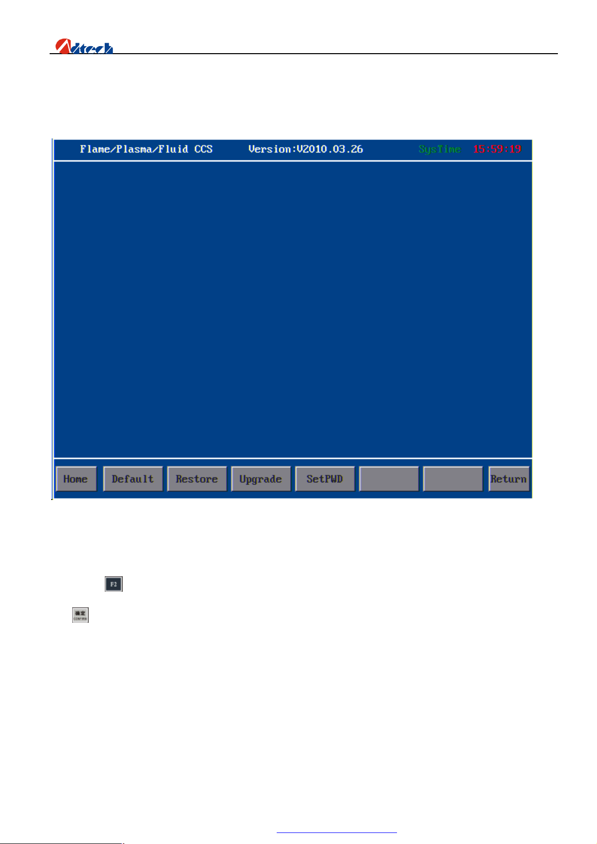
ADT-HC6500 Flame/Plasma/Fluid Controller
Ø System management
In system management interface as shown below, software upgrades, Standard value, Vista Ghost, Factory setting
functions etc.
System management
Factory default
Press (Factory default), and the interface is shown as follows. Choose “System parameters restore” and
press to go to the next step when the system will prompt you to enter password “360”. If the password is valid, it
will go to the next interface. You can cancel at this time or press “CONFIRM” to restore the parameters of current
cutting mode to the saved factory default. If the parameters have been restored, the interface will pause for 1 second
and restart the system using the restored parameters. As the following picture shows:
73
PDF 文件使用 "pdfFactory Pro" 试用版本创建 www.fineprint.com.cn
Page 75
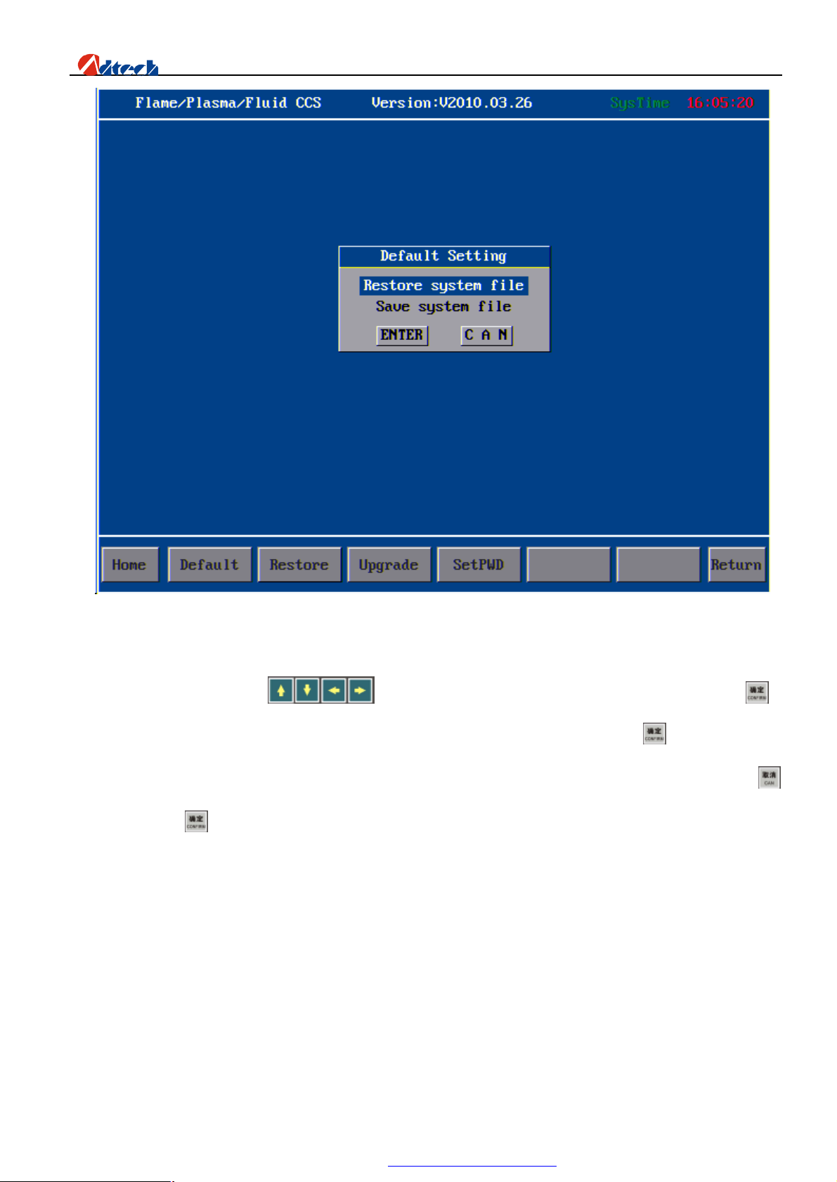
ADT-HC6500 Flame/Plasma/Fluid Controller
Interface of factory default setup
“Save system parameters”: Press to move the cursor to “Save the system parameters” and press to
go to the next step when the system will prompt you to enter password. Enter“361”, and press to continue. If the
password is invalid, the setup will exit; if the password is valid, it will go to the next step. Likewise, you can press
to cancel or press to save the parameters of current cutting mode as the factory defaults. The setup method is the
same as that of restoring the parameters.
One-Key Recovery
One-key recovery function is used to backup or restore the system files. It is designed for preventing the loss of
system files caused by the formatting and error in operation. You need to backup the system files when initializing, so
that when the system file lost, you can restore the files to recover the system.
Software upgrade
Upgrade function is provided for users to upgrade the application software to the latest version. In system management
74
PDF 文件使用 "pdfFactory Pro" 试用版本创建 www.fineprint.com.cn
Page 76
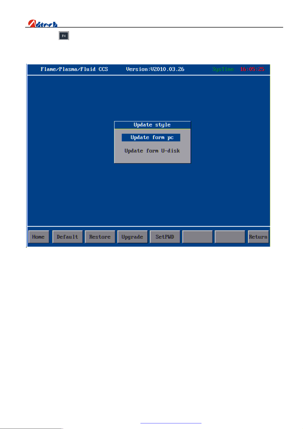
ADT-HC6500 Flame/Plasma/Fluid Controller
interface, press key and the interface of “Choose the upgrade mode” will show up. Two modes of upgrading are
provided, upgrade via PC and upgrade via USB disk.
As the following picture show:
Choose the upgrade mode
USB disk connected
When the cursor is moved to “Upgrade via USB disk”, the system will start the USB disk function. If the system
finds the USB disk, it means the USB disk is connected successfully. As the following picture shows:
75
PDF 文件使用 "pdfFactory Pro" 试用版本创建 www.fineprint.com.cn
Page 77
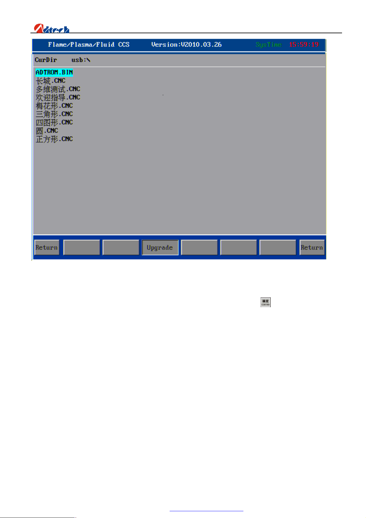
ADT-HC6500 Flame/Plasma/Fluid Controller
USB disk connected
Once the USB disk is connected, move the cursor to “ADTROM.BIN” and press , the system will then start
upgrading automatically. After the upgrade, you need to restart the system and record the program. For program
recording, please see the later chapter.
If the files selected are not the system files for upgrading, the system will give an upgrade failure prompt or other
info.
Upgrade via PC
76
PDF 文件使用 "pdfFactory Pro" 试用版本创建 www.fineprint.com.cn
Page 78
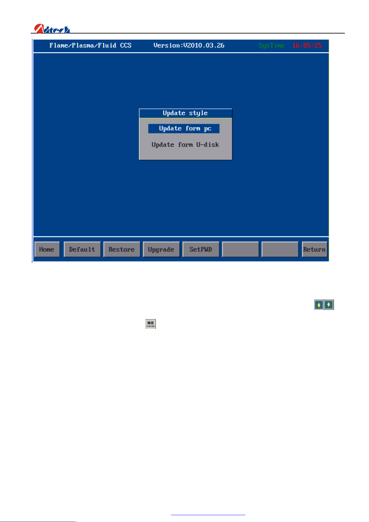
ADT-HC6500 Flame/Plasma/Fluid Controller
Connect the PC
Connect one end of the USB line to PC and the other end to the interface of controller, and then press to
move cursor to “Upgrade via PC” and press . Open “My Computer” and the controller will be displayed as a
64M USB disk on the computer. Double click “Removable USB disk” and the following interface shows up,
which include all system files of the controller.
77
PDF 文件使用 "pdfFactory Pro" 试用版本创建 www.fineprint.com.cn
Page 79
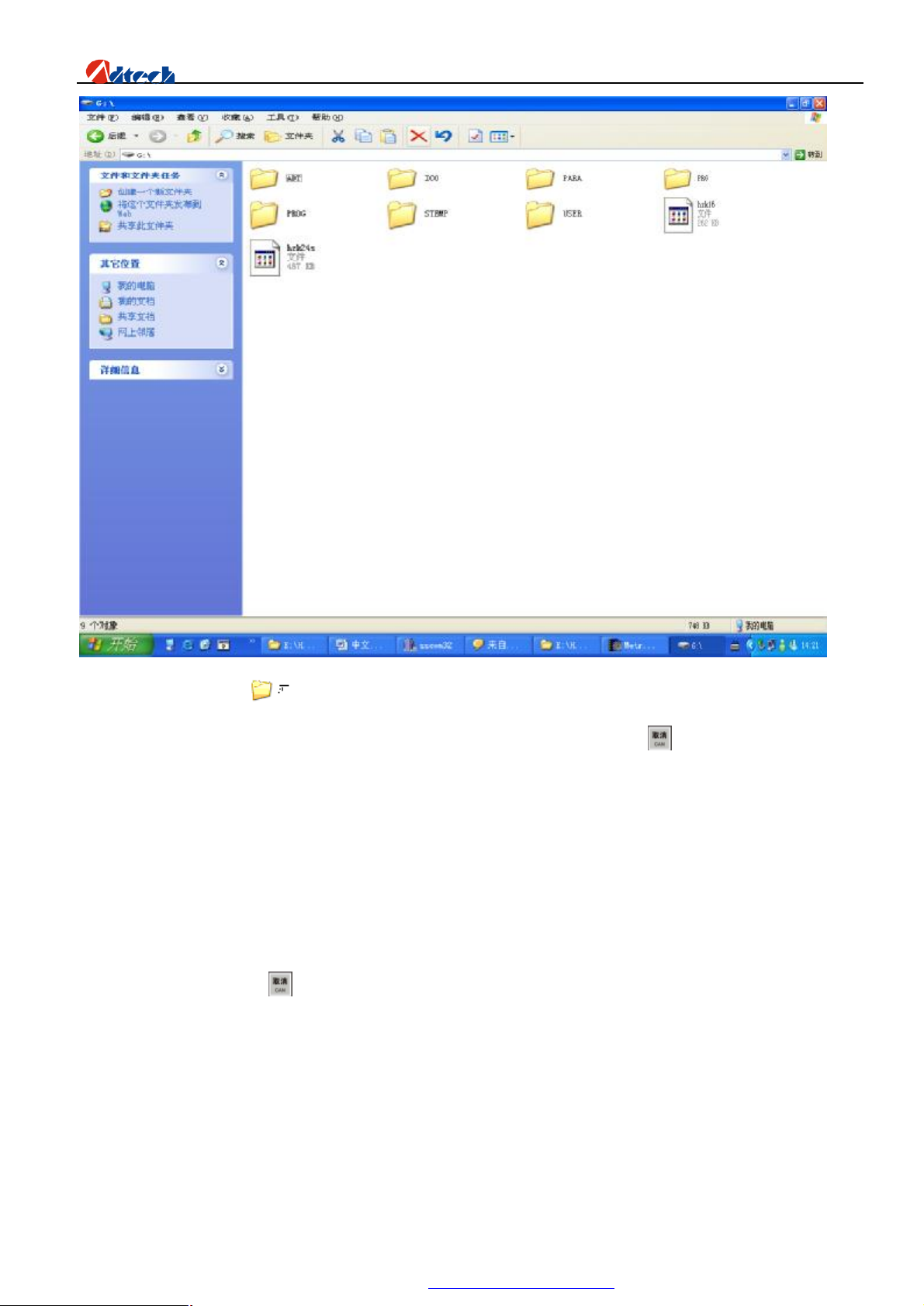
ADT-HC6500 Flame/Plasma/Fluid Controller
Then, double click to open this folder, copy the software named “adtrom.bin” to “ADT” folder in
the following picture to cover the original “adtrom.bin” file. After the copy, press key on controller, and the
system will restart automatically to record the latest program to BIOS chip.
Ø Recording program
When you have copied the latest application software to controller, you need to save the software to the
controller BIOS so that the controller can operate the software. To do this, you should cut the controller power
supply first, press and hold key when the controller is restarted. The BIOS setup interface is shown as
follows:
78
PDF 文件使用 "pdfFactory Pro" 试用版本创建 www.fineprint.com.cn
Page 80
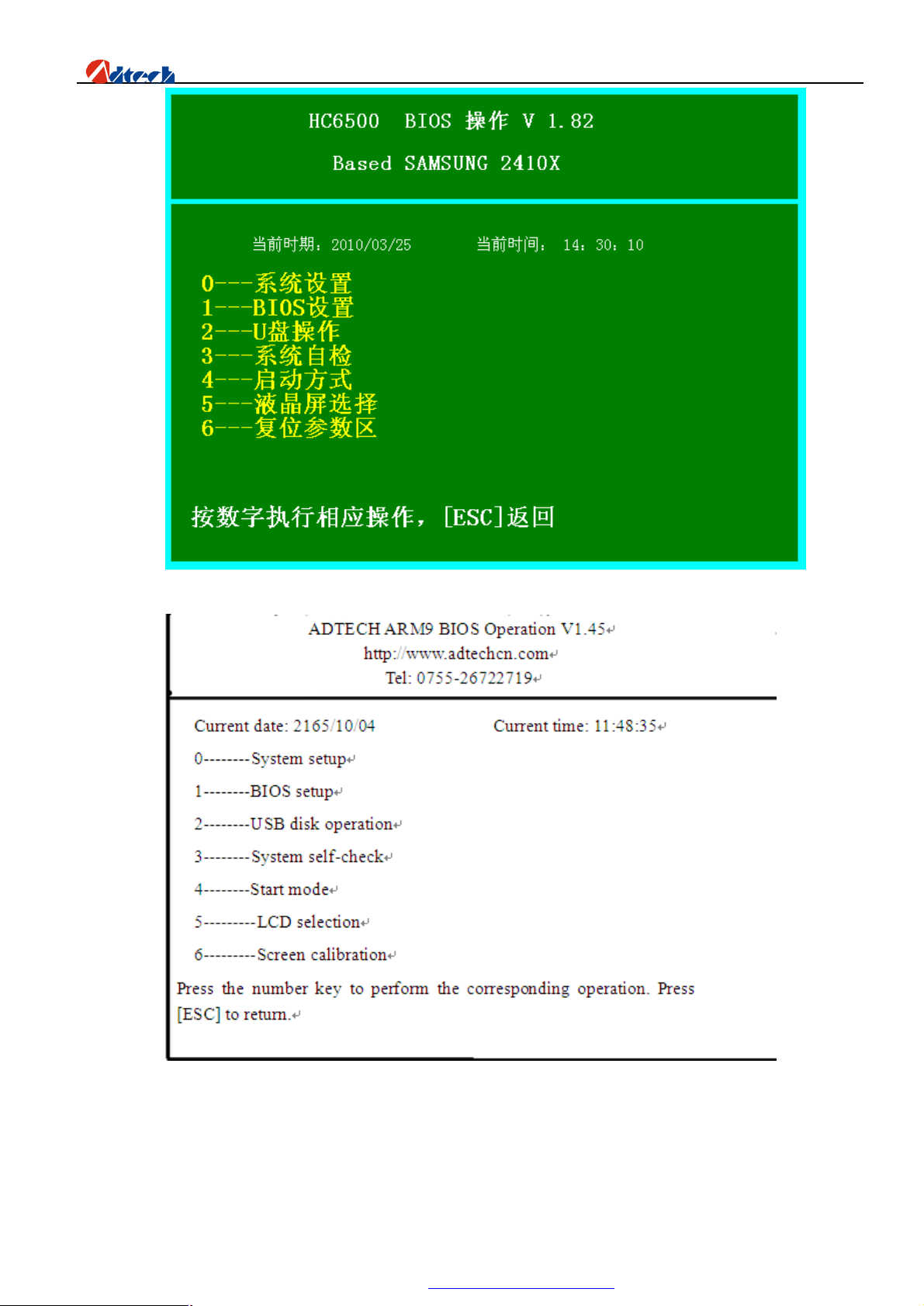
ADT-HC6500 Flame/Plasma/Fluid Controller
Picture 60 BIOS setup interface
Press number key “1---BIOS setup” and the system will prompt you to enter the password. Please refer to the supplier
for the password. Enter the password, and the interface is shown as follows:
79
PDF 文件使用 "pdfFactory Pro" 试用版本创建 www.fineprint.com.cn
Page 81
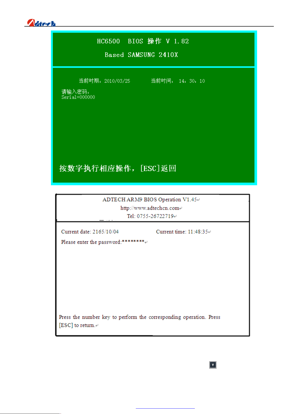
ADT-HC6500 Flame/Plasma/Fluid Controller
Password entry interface of the BIOS interface
The system will enter the setup interface of the password is valid. Press the corresponding number key “Program
upgrading” and the system will prompt “Sure to upgrade the program, Y/N?” Then, press key, and the system will
indicate that the files are found, and start upgrading. After the upgrading, a prompt “Upgrade complete, please restart
80
PDF 文件使用 "pdfFactory Pro" 试用版本创建 www.fineprint.com.cn
Page 82
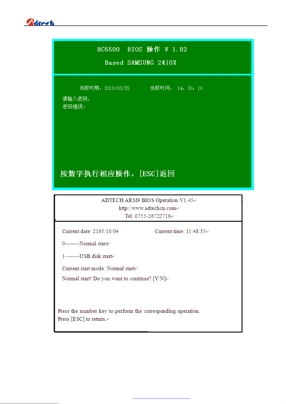
ADT-HC6500 Flame/Plasma/Fluid Controller
the machine” will show up. If the password is invalid, the interface will be shown as follows:
Picture63 Password error interface of BIOS interface
Enter the password again and repeat the operations above.
Check whether the start mode is “Normal start” after the upgrading.
81
PDF 文件使用 "pdfFactory Pro" 试用版本创建 www.fineprint.com.cn
Page 83
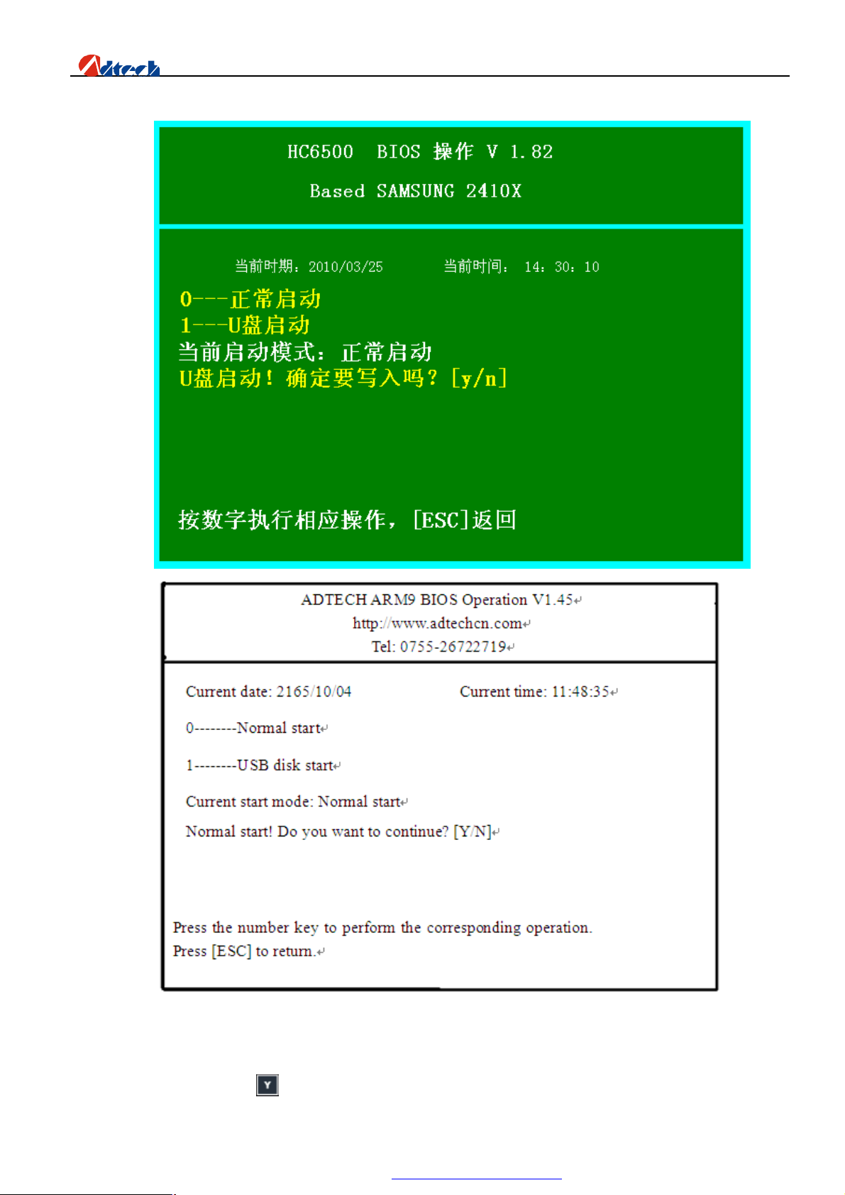
ADT-HC6500 Flame/Plasma/Fluid Controller
Picture64 Start Mode
Press the corresponding number key “1---Normal start”, and the system will prompt “Normal start! Do you
want to continue? [y/n]”. Press to set the system to “Normal start”.
82
PDF 文件使用 "pdfFactory Pro" 试用版本创建 www.fineprint.com.cn
Page 84
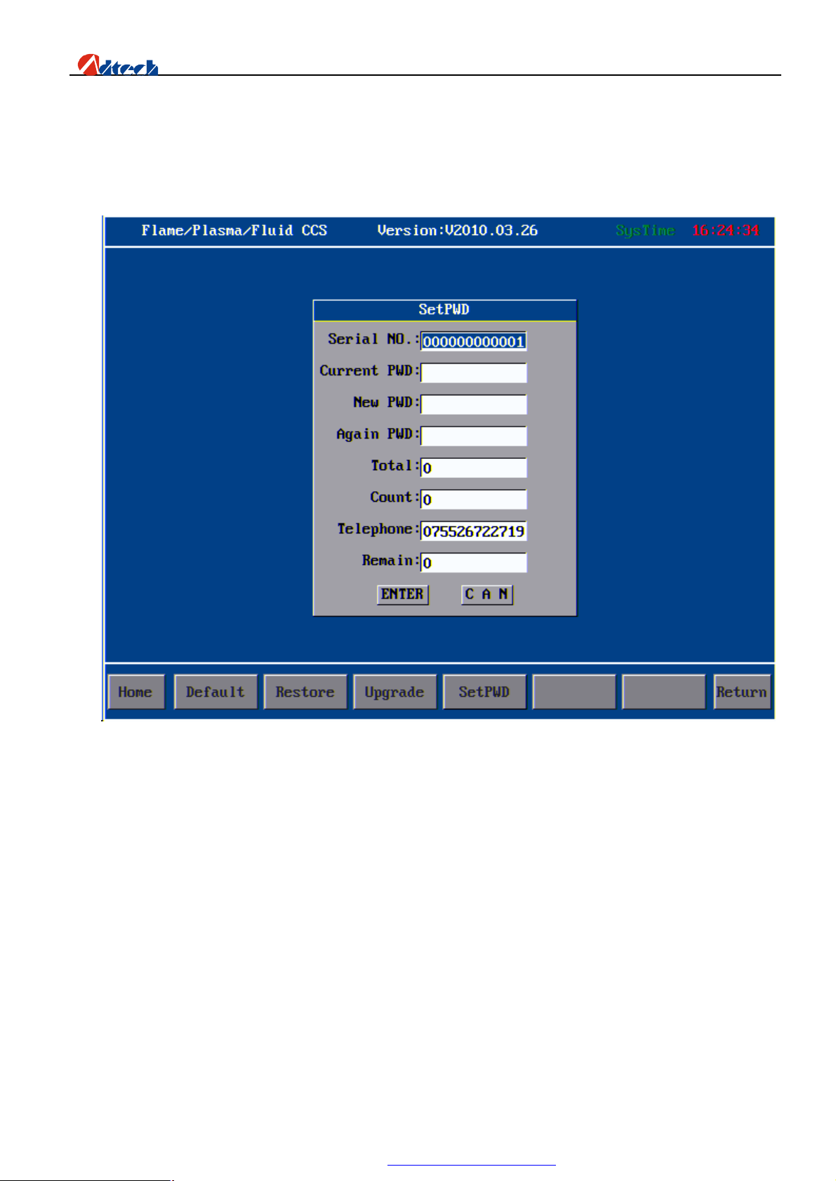
ADT-HC6500 Flame/Plasma/Fluid Controller
Ø Manufactory Setup
In “Setup options” ->“System management”->“manufactory setup”, you can set several parameters, such as
system S/N, password, the allowable times of boot-up, reminding times, etc. Here we are going to introduce these
functions one by one:
S/N: Mark of a control system. One control system has one exclusive S/N. It is a series of pure number, and can
be changed if you enter a valid password.
Current password: It is the current system password. You should remember the new password if you have
changed it. The default password of ADTECH control system is “26722719”.
New password: It is the new password you want to change to. You need not input any value in this item if you are
not going to change the password.
Confirm the password: Check whether the two passwords you entered are consistent.
Total times: If it is empty, the system would not restrict the application times. If it is a number, the times of
applying control system is restricted.
Reminding times: If restricted password is set for the system, a reminding time for payment should be set to
remind user to contact system supplier in advance.
Contact number: It is a contact number of cutting machine supplier provided for the convenience of after-sale
service. However, do not forget the password.
Remaining times: It indicates the remaining times of system application.
When the remaining time reaches the set number, the system will remind you as you start the system (as the
83
PDF 文件使用 "pdfFactory Pro" 试用版本创建 www.fineprint.com.cn
Page 85
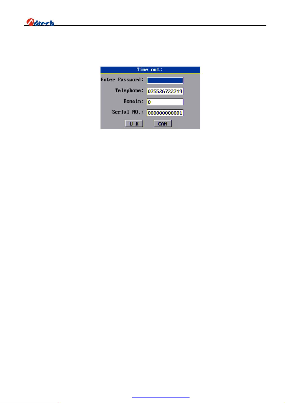
ADT-HC6500 Flame/Plasma/Fluid Controller
picture shows). If the remaining time is larger than 0, you can press cancel to go on using. If it is 0, you need to enter
password and press [CONFIRM]. If the password is invalid, this dialogue box would not disappear and the system
cannot be used until you enter a valid password. This prompt would not appear again until you reset the password and
the remaining times.
Note: For the application times, it counts once every time when the system is started.
84
PDF 文件使用 "pdfFactory Pro" 试用版本创建 www.fineprint.com.cn
Page 86
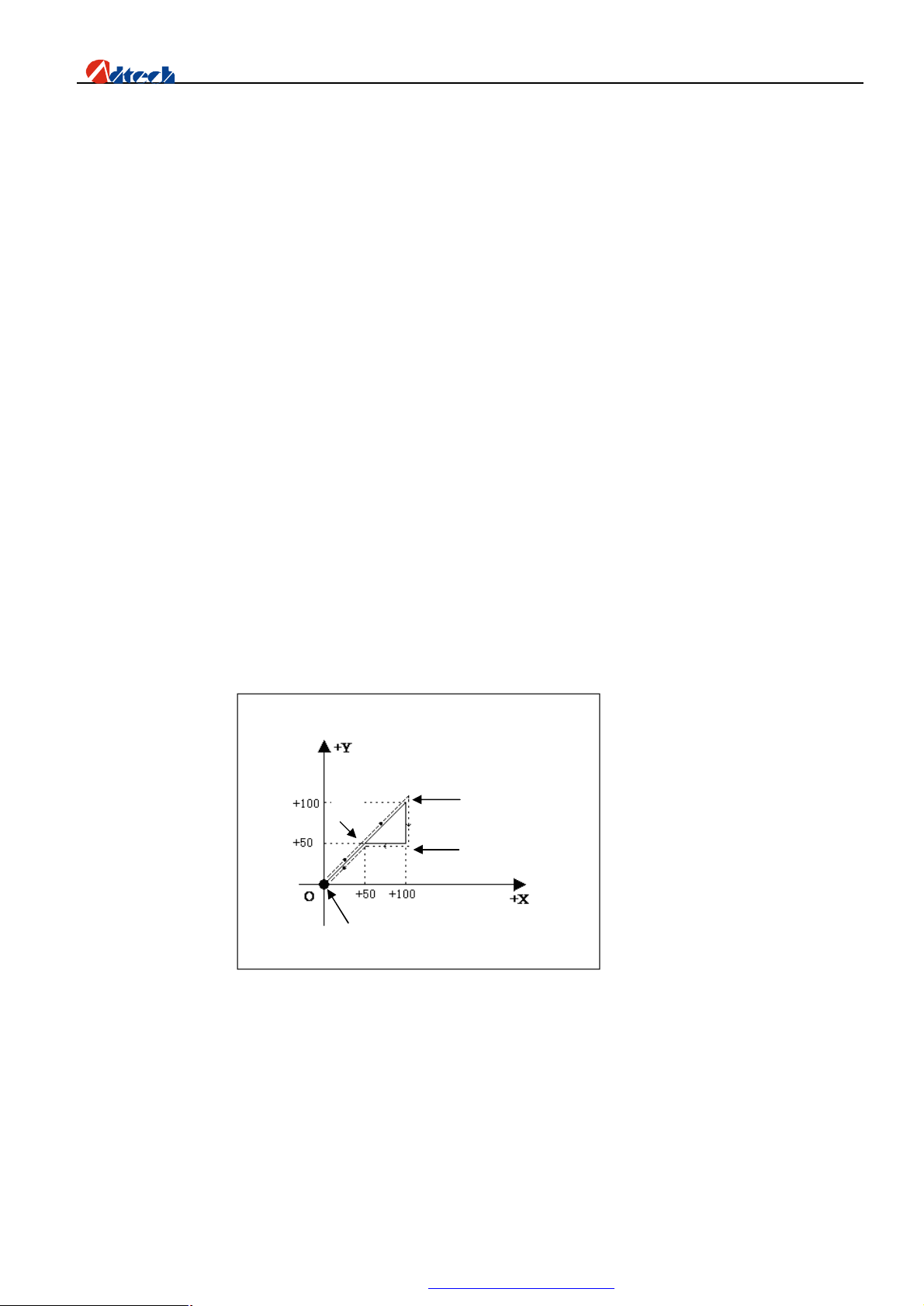
ADT-HC6500 Flame/Plasma/Fluid Controller
B
A
C D
Chapter IV Instruction System
Ø Explanation of programming symbol
Every motion of the CNC processing is done following the due process, every processing program is composed
by several instruction segments, each instruction segment is composed by several function words, and each function
word should be started with a letter following by the parameter value.
Definition of function word:
G Preparatory function
M M-function
L Cycle index or delay time
X Coordinate of X axis: It is relative coordinate in G91 (default), and absolute coordinate in G90.
Y Coordinate of Y axis: It is relative coordinate in G91 (default), and absolute coordinate in G90.
I during the circular arc processing, the center coordinate value minus the original value of X axis
J during the circular arc processing, the center coordinate value minus the original value of Y axis
R Specify the radius of circular arc
Ø Coordinate explanation
Ø Relative coordinate
In coordinate system, if the coordinate of current point is calculated from the previous coordinate, it is called
relative coordinate. As the picture shows:
Picture 2.1
As the above picture, if calculated by relative coordinate, the coordinate of the points in picture are as follows:
1. Point A is the origin, the coordinate is (X0, Y0);
2. Point B is (X50, Y50) relative to point A;
3. Point C is (X50, Y50) relative to point B;
4. Point D is Y-50 relative to point C;
5. Point D returns to point B, and the coordinate is X-50;
85
PDF 文件使用 "pdfFactory Pro" 试用版本创建 ÿ www.fineprint.com.cn
Page 87
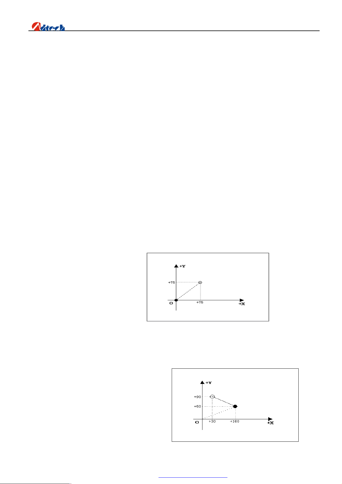
ADT-HC6500 Flame/Plasma/Fluid Controller
Ø Absolute coordinate
In coordinate system, if the coordinate of current point is calculated from the origin, it is called absolute
coordinate. As picture 2.1, if calculated by absolute coordinate, the coordinate of the points in picture are as follows
1. Point A is the origin, the coordinate is (X0, Y0);
2. Point B is (X50, Y50) relative to point A;
3. Point C is (X100, Y100) relative to point A;
4. Point D is (X100, Y50) relative to point A;
5. Point D returns to point B, and is (X50, Y50);
Ø G instruction explanation
Ø G92 reference point setup
Set the coordinate of processing origin (reference point) of program. It should be put at the beginning of program.
Format: G92 X0 Y0
If G92 is not followed with X/Y coordinate, the current coordinate (X, Y) is taken as the reference point. Usually,
when locating using the machine origin, G92 would not have X and Y content.
Ø G00 idle motion
This instruction enables you to travel to the appointed position quickly. During the travel, the system moves from
the starting point to end point in rectilinear motion at the manual limiting speed. G00 motion would not be influenced
by the speed rate.
Format: G00 Xn Yn
For example: G92 X0 Y0
G00 X75 Y75
M02
● Current position of cutting gun
○ Expected position of cutting gun
Ø G01 linear cutting
This instruction enables you to feed the cutting gun to the appointed position in linear way. As the cutting motion
instruction, single-axis or dual-axis linear interpolation is available.
Format: G01 Xn Yn
For example:
G92 X0 Y0
G90
G00 X100 Y50
G01 X-30 Y90
M02
86
PDF 文件使用 "pdfFactory Pro" 试用版本创建 ÿ www.fineprint.com.cn
Page 88
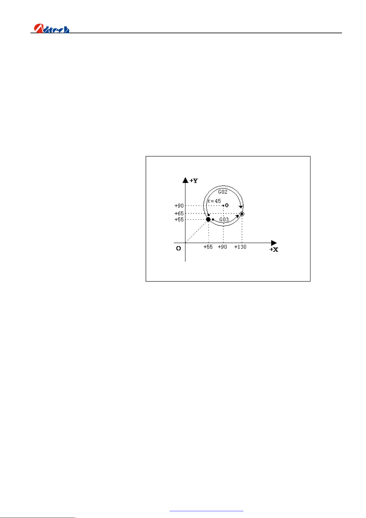
ADT-HC6500 Flame/Plasma/Fluid Controller
arc
clockwise
●Current position of cutting gun
○Expected position of cutting gun
Ø G02/G03 circular arc cutting
This instruction is used to cut a circle or circular arc. The circle is divided into G02 (clockwise) and G03
(anti-clockwise).
Format: G02[03] Xn Yn In Jn
Foe example (G02):
G92 X0 Y0
G00 X55 Y55
G02 X75 Y10 I35 J35
M02
Note: Cut a section of circular
For example (G03):
G92 X0 Y0
G00 X55 Y55
G03 X75 Y10 I35 J35
M02
●Current position of cutting gun
○Expected position of cutting gun
Explanation:
I and J are the increment of center at X and Y-axis direction relative to the origin. When you are writing
processing files, if you want to write a circle with a diameter of 100MM, to make it simple you can enter I50 J0
directly. If the circle diameter is 150MM, you can just enter I75 J0.
Ø G04 Pause/Delay instruction
This instruction is used to set the time delay. When the program performs this instruction, it will delay the stated
time. The time unit is in second.
Format: G04 Ln
For example: G04 L3.6 (3.6s delay)
If G04 does not have Ln behind, the system will delay without time limit once G04 is performed until you press
[Start] key.
87
PDF 文件使用 "pdfFactory Pro" 试用版本创建 ÿ www.fineprint.com.cn
Page 89

ADT-HC6500 Flame/Plasma/Fluid Controller
Ø G26, G27, G28 Back to reference point
This instruction allows the cutting torch to return to reference point automatically.
Format:
G26: X axis back to reference point
G27: Y axis back to reference point
G28: X and Y axes back to reference point at the same time
For example: G28 (X and Y axes back to reference point at the same time, equal to run G00)
Ø G22/G80 cycle processing
This instruction can be used to perform cycle processing. G22 is the beginning of loop, and cycle time L is
appointed. G80 is the end mark of loop. G22 and the nearest G80 below form a loop.
Format: G22 Ln_ (L specifies the cycle times)
Loop
G80 (End mark of loop)
For example: 0000 G92 X100 Y100
0001: G22 L10000 ——Cycle starts
0002: G00 X50 Y50
0003: G01 X80 Y80
0004: G80 ——Cycle ends
0005: M02
Ø G81 workpiece counting
This instruction is used by the system to count the total workpiece automatically.
Format: G81
For example: 0000 G92 X0 Y0
0001: G22 L3——Cycle starts
0002: G01 X50 Y50
0003: G81——Counting
0004: G80——Cycle ends
0005: M02
88
PDF 文件使用 "pdfFactory Pro" 试用版本创建 www.fineprint.com.cn
Page 90

ADT-HC6500 Flame/Plasma/Fluid Controller
Ø Common M instructions
1) Common M instructions:
Users only need to know the functions of M07, M08, and M02 instructions. M07 refers to fixed cycle of
preheating and perforating. When the track is processed and come to perform M08, the system will close all related
valves. In the end, perform M02 to finish the processing. Detailed functions of codes are as follows:
Flame:
M07 ① Fixed cycle of preheating and perforating, operating sequence is as follows:
1. Open acetylene valve;
2. Ignition on;
3. Drop the cutting gun;
4. Open the preheating valve and start preheating;
5. Lift the perforating cutting gun;
6. Open cutting oxygen valve;
7. Drop the perforating cutting gun;
8. Perforation complete, and go to the next motion.
M08 ② Close the cutting fixed cycle. The operating sequence is as follows:
Plasma:
①
1. Close the cutting oxygen valve;
2. Lift the cutting gun.
A). with height-adjusting system:
• Enable M22
‚ Arcing M12
ƒ Waiting for arc voltage detection signal (IN0)
After arcing, the height-adjusting control starts performing initial location (With initial location
function), perforating and perforating delay automatically, and gives a signal of successful arc
voltage detection to the controller.
B). without height-adjusting system:
• Arcing, arcing delay M12
‚ Perforating, perforating delay
C). Start the following actions
②
1. Close striking arc M13
89
PDF 文件使用 "pdfFactory Pro" 试用版本创建 www.fineprint.com.cn
Page 91

2. Close the height-adjusting control M23
M02 ③ program end instruction
2)other M instructions:
M10/M11 ① switch of acetylene valve, M10 (Open), M11 (Closed)
M12/M13 ② switch of cutting control valve, M12 (Open), M13 (Closed)
③ M14/M15 switch for controlling the rise of cutting gun, M14 (Open), M15 (Closed)
M20/M21 ④ ignition switch, M20 (Open), M21 (Closed)
M24/M25 ⑤ switch of preheating oxygen valve, M24 (Open), M25 (Closed)
M52 ⑥ ignition fixed cycle (controlled by time in “Cutting type”)
M70 ⑦ fixed cycle of cutting gun rising (controlled by time in “Cutting type”)
M71 ⑧ fixed cycle of cutting gun falling (controlled by time in “Cutting type”)
ADT-HC6500 Flame/Plasma/Fluid Controller
M72 ⑨ fixed cycle of perforating cutting gun rising (controlled by time in “Cutting type”)
M73 ⑩ fixed cycle of perforating cutting gun falling (controlled by time in “Cutting type”)
M74 ⑾ fixed cycle of preheating (controlled by time in “Cutting type”)
M80 ⑿ main switch, all output ports are closed if M80 is performed.
Annex I. Illustration of edition and processing
Press key in main interface to enter the edition option interface, where you can press key to create a new
processing file. Then, you can enter a file name and press key to enter the file edition interface. In this chapter, we
take cutting the following figure as an example. (Dashed line and arrow refer to the direction of motion, solid line
refers to the track of cutting, and “●” is the starting point of cutting.)
Remark: Because absolute coordinate is not used often, we do not introduce it in this chapter. In this chapter,
we use the relative coordinate.
90
PDF 文件使用 "pdfFactory Pro" 试用版本创建 www.fineprint.com.cn
Page 92
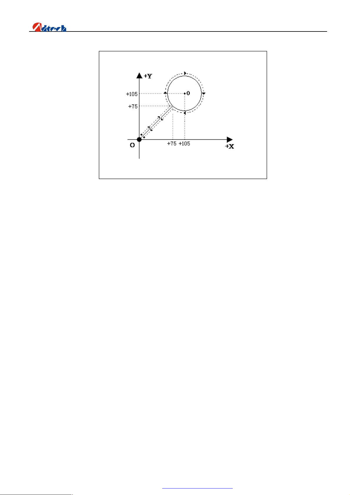
Ø Standard circle
The program is as follows:
ADT-HC6500 Flame/Plasma/Fluid Controller
1) Relative coordinates programming and explanation of graph codes:
0000: G92 X0 Y0——set the reference point;
0001: G22 L3——L: set the processing loops; “3” means loop for 3 times;
0002: M07——It is the preheating perforating function. Prompt: Please set all the time
parameters in flame or plasma control option in the parameter setup according
to the actual demand.
0003: G01 X75 Y75——perforating and wire bonding;
0004: G02 I30 J0——Clockwise circle processing;
0005: M08——Preheating oxygen, acetylene, and cutting oxygen valves closed;
0006: G00 X-75 Y-75——travel to the origin at the highest manual speed;
0007: G81——Counting instruction, it counts once for each loop automatically;
0008: G80——cycle ends;
0009: M02——processing ends
91
PDF 文件使用 "pdfFactory Pro" 试用版本创建 www.fineprint.com.cn
Page 93
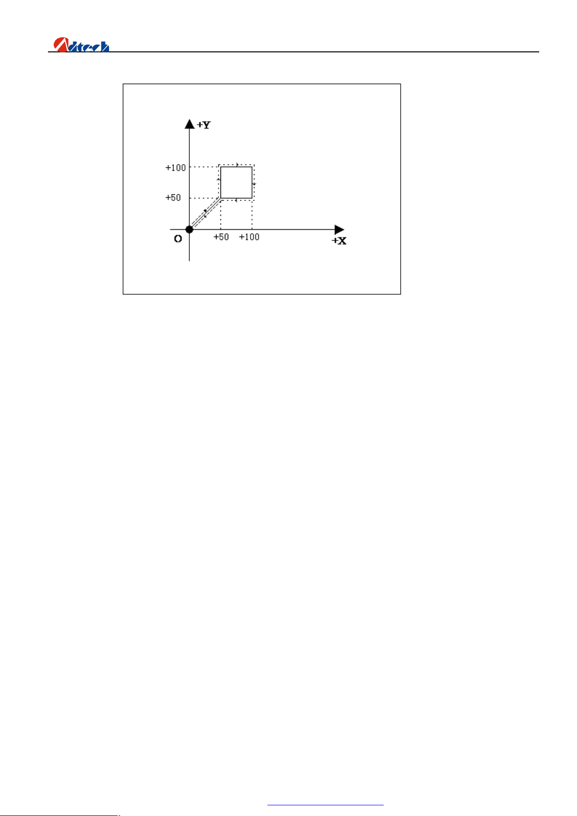
ADT-HC6500 Flame/Plasma/Fluid Controller
Ø Square
1) Relative coordinates programming and explanation of graph codes:
0000: G92 X0 Y0
0001: M07——Perforating;
0002: G01 X50 Y50——Perforation and wire bonding;
0003: Y50——the first side, if the above instruction is G01, this G01 as well as X0 of this
instruction cannot omitted for the convenience of editing codes manually.
0004: X50——the second side;
0005: Y-50——the third side;
0006: X-50——the four side;
0007: M08——close the cutting oxygen
0008: G00 X-50 Y-50——travel to the origin at the highest manual speed;
0009: M02——processing ends
92
PDF 文件使用 "pdfFactory Pro" 试用版本创建 www.fineprint.com.cn
Page 94
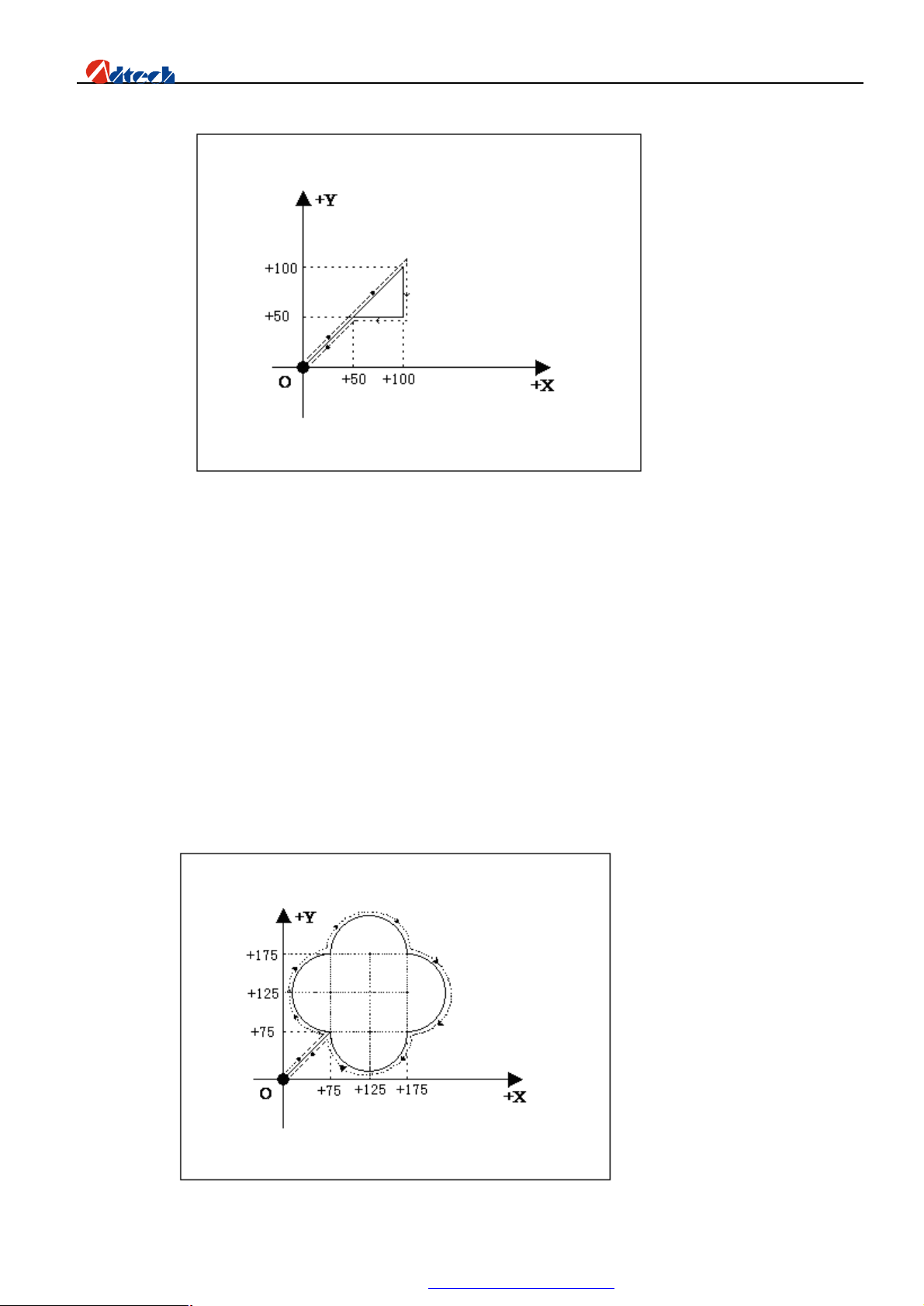
Ø Triangle
1) Relative coordinate programming
ADT-HC6500 Flame/Plasma/Fluid Controller
Ø Quincunx
0000: G92 X0 Y0
0001: G01 X50 Y50
0002: X50 Y50
0003: Y-50
0004: X-50
0005: G00 X-50 Y-50
0006: M02
93
PDF 文件使用 "pdfFactory Pro" 试用版本创建 www.fineprint.com.cn
Page 95

1) Relative coordinate programming
0000: G92 X0 Y0
0001: G01 X75 Y75
0002: G02 Y100 I0 J50
0003: X100 I50 J0
0004: Y-100 I0 J-50
0005 : X-100 I-50 J0
0006 : G01 X-75 Y-75
0007 : M02
Ø Four figures
ADT-HC6500 Flame/Plasma/Fluid Controller
1)Relative coordinate programming
0000: G92X0Y0
0001: G22 L100
0002: G0 X50
0003: G1 Y200
0004 : X200
0005 : Y-200
0006 : X-200
0007 : G00 Y400
0008 : G1 Y50
94
PDF 文件使用 "pdfFactory Pro" 试用版本创建 ÿ www.fineprint.com.cn
Page 96

0009 : G2 X50 Y50 I50 J0
0010 : G1 X100
0011 : G2 X50 Y-50 I0 J-50
0012 : G1 Y-100
0013 : G2 X-50 Y-50 I-50 J0
0014 : G1 X-100
0015 : G2 X-50 Y50 I0 J50
0016 : G1 Y50
0017 : G00 X400 Y50
0018 : G2 X100 Y0 I50 J0
0019: Y-100 I0 J-50
0020: X-100 I-50 J0
ADT-HC6500 Flame/Plasma/Fluid Controller
0021: Y100 I0 J50
0022 : G00 X-50 Y-350
0023 : G2 X0 Y0 I100 J0
0024 : G0 X-400 Y-100
0025 : G81
0026:G80
0027 : M02
95
PDF 文件使用 "pdfFactory Pro" 试用版本创建 www.fineprint.com.cn
Page 97
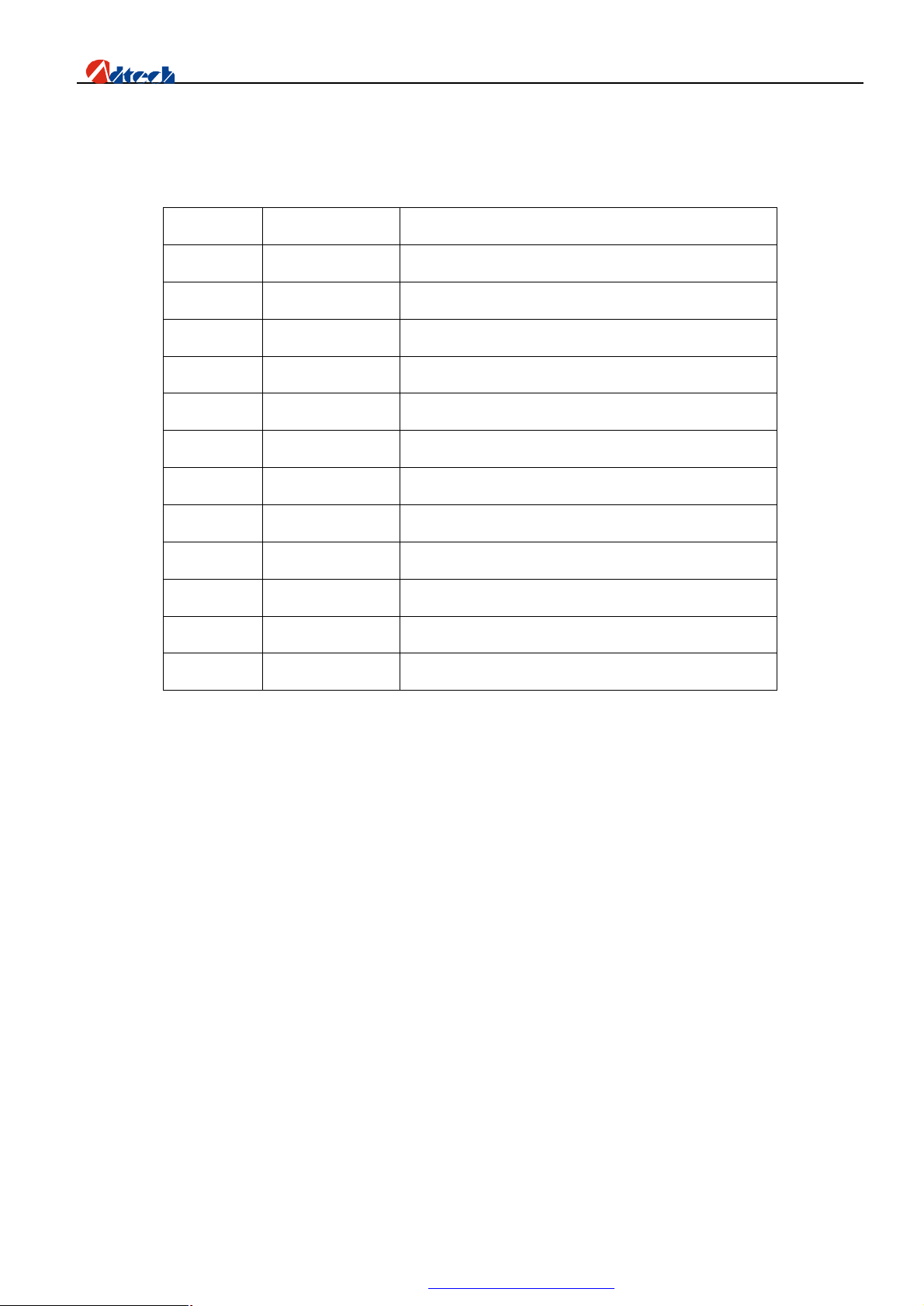
ADT-HC6500 Flame/Plasma/Fluid Controller
axes return to reference point at the same time
Annex II. G Instruction Quick Reference
S/N Name of Instruction
1 G00 Quick point and position motion (Dry run)
2 G01 Linear processing
3 G02 Clockwise circle processing
4 G03 Anti-clockwise circle processing
5 G04 Pause/Delay
6 G26 X axis returns to reference point
7 G27 Y axis returns to reference point
8 G28 X and Y
9 G22 Cycle starts (should be used combining G80)
10 G80 Cycle ends (should be used combining G22)
11 G81 Counting function
12 G92 Set the reference point of processing
Explanation
96
PDF 文件使用 "pdfFactory Pro" 试用版本创建 www.fineprint.com.cn
Page 98
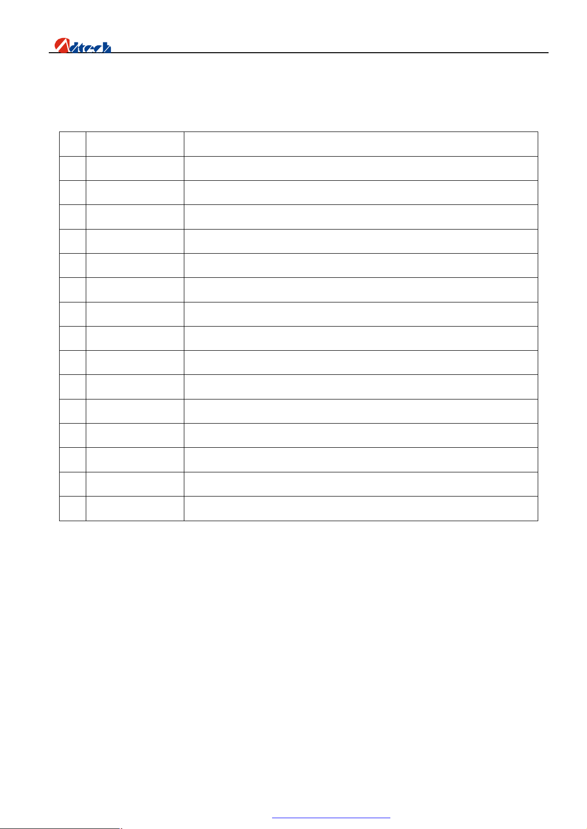
ADT-HC6500 Flame/Plasma/Fluid Controller
Annex III. M Instruction Quick Reference
S/N Name of Instruction
1 M02 Program ends
2 M07 Start the fixed cycle of preheating and perforating
3 M08 Close the fixed cycle of cutting oxygen
4 M10/M11 switch of acetylene valve, M10 (Open), M11 (Closed)
5 M12/M13 switch of control valve, M12 (Open), M13 (Closed)
6 M14/M15 switch for controlling the rise of cutting gun, M14 (Open), M15 (Closed)
7 M20/M21 ignition switch, M20 (Open), M21 (Closed)
8 M24/M25 switch of preheating oxygen valve, M24 (Open), M25 (Closed)
9 M52 ignition fixed cycle (controlled by time in “Cutting type”)
10 M70 fixed cycle of cutting gun rising (controlled by time in “Cutting type”)
11 M71 fixed cycle of cutting gun falling (controlled by time in “Cutting type”)
Explanation
12 M72 fixed cycle of perforating cutting gun rising (controlled by time in “Cutting type”)
13 M73 fixed cycle of perforating cutting gun falling (controlled by time in “Cutting type”)
14 M74 fixed cycle of preheating (controlled by time in “Cutting type”)
15 M80 main switch, all output ports are closed if M80 is performed
97
PDF 文件使用 "pdfFactory Pro" 试用版本创建 www.fineprint.com.cn
Page 99
ADT-HC6500 Flame/Plasma/Fluid Controller
Annex IV. Troubleshooting
Failure S/N Failure description Inspection item
Abnormal
motion
Cutting
quality
1 The motor does not run, or goes to dead
state during the auto processing
2 The motor does not run, or goes to dead
state during the manual operation
3 The processing code has instruction of
back-to-reference, but the system does
not go back to reference point after
having finished the track.
4 There is error in accuracy. Re-calibrate the “Accuracy” in “Parameter”
5 The right angle of square being cut is
out of the vertical
Check whether “Speed limit in auto mode” is
set to the proper speed, and whether the
manual processing percentage is low.
Check whether the manual speed limit is set
to the proper speed, and whether the manual
percentage is low.
Check whether the manual speed limit is set
to the proper speed, and whether the manual
percentage is low.
Re-adjust the start-up speed and acceleration
in “speed” in “Parameter”.
Abnormal
operation
Others
6 There is wave vibration in opposite
angle when cutting the circle.
7 The cutting torch does not move when
you press in the main interface.
8 The air valve does not work or the
external switch does not work.
9 The anti-interfere performance of
plasma is poor.
10 USB disk cannot be detected. Enter the USB disk formatting interface via
Please adjust the reversal clearance in
“Adjustment” in “ Parameter”.
Check whether the selected processing files
have processing codes, or whether the system
has resisted the limit.
Enter the “Diagnosis” interface and test the
relevant items.
Check whether the grounding is in good
condition.
PC and change the original format to
“FAT32” or “FAT” , or change the USB disk.
98
PDF 文件使用 "pdfFactory Pro" 试用版本创建 www.fineprint.com.cn
 Loading...