


ADT-8840
ADT-8840 Four-Axis Off-Line Motion
Control Card
User’s Manual
ADTECH (SHENZHEN) CNC TECHNOLOGY CO. LTD
Add: 5/F, Building 27-29, Tianxia IC Industrial Park, Yiyuan Road, Nanshan District, Shenzhen P.C.: 518052 Tel: 0755-26722719 (20-line) Fax: 0755-26722718 E-mail Adtech@21cn.com http://www.adtechcn.com

ADT-8840 Four-Axis Off-Line Motion Control Card User’s Manual
Declaration on Copyright
The copyright of all parts in this Manual is reserved by ADTECH (SHENZHEN) CNC TECHNOLOGY CO. LTD (hereinafter referred to as “ADTECH”) and, without permission by ADTECH, nobody shall reproduce, copy, transcribe or translate any part therein. No part of this Manual shall be considered as warranty, expression of standpoint or other implications in any form whatsoever. If any information is disclosed, either directly or indirectly, any profit is lost or undertaking is terminated just because of the information indicated in this Manual or on the product it describes, ADTECH and its employees shall bear no responsibility. In addition, the specifications and other materials mentioned in this Manual shall only be used for reference and the contents therein shall be subject to change without prior notice.
Trademark
The product names are only mentioned in this Manual for the purpose of identification, which may be the trademark of others or whose copyright is reserved by others. We hereby declare that:
INTEL and PENTIUM are the trademarks of Intel Corporation;
WINDOWS and MS—DOS are trademarks of Microsoft Corporation;
ADT-8840 is the trademark of ADTECH;
Marks not mentioned here belong to their respective companies that underwent the registration procedures.
All rights reserved.
ADTECH (SHENZHEN) CNC TECHNOLOGY CO. LTD
http://www.adtechcn.com |
1 |
|
Contents |
|
Chapter I |
Overview ....................................................................................................... |
7 |
)About the prodcut ........................................................................................................................... |
7 |
|
)Features........................................................................................................................................... |
|
7 |
)Specification ................................................................................................................................... |
8 |
|
)Outer dimensions ............................................................................................................................ |
9 |
|
)Operating environment ................................................................................................................. |
10 |
|
)Application.................................................................................................................................... |
10 |
|
Chapter II |
Electric Wiring ........................................................................................ |
10 |
)Illustration and definition for terminals ....................................................................................... |
.11 |
|
)Connecting to power supply ........................................................................................................ |
.20 |
|
)Standard USB interface (USB) .................................................................................................... |
.21 |
|
)Standard Ethernet interface (RJ45) ............................................................................................... |
21 |
|
)Connection for input signal........................................................................................................... |
21 |
|
)Connection for pulse output signal ............................................................................................... |
22 |
|
)Connection for output signal......................................................................................................... |
23 |
|
)Connection for communication signal .......................................................................................... |
23 |
|
Chapter III |
Features.................................................................................................. |
24 |
)Preset drive.................................................................................................................................... |
24 |
|
)Continuous drive........................................................................................................................... |
25 |
|
)Velcoity curve ............................................................................................................................... |
25 |
|
)Set-speed drive.............................................................................................................................. |
25 |
|
)Speed mode................................................................................................................................... |
27 |
|
)Buffer mode .................................................................................................................................. |
27 |
|
)Position management .................................................................................................................... |
28 |
|
)Interpolation.................................................................................................................................. |
29 |
|
)Pulse output mode......................................................................................................................... |
30 |
|
)Hardware limit signal.................................................................................................................... |
31 |
|
)Signal corresponding to server motor ........................................................................................... |
31 |
|
)Drive by external signal ................................................................................................................ |
31 |
|
Chapter IV |
Basic Library Functions of ADT8840.................................................... |
32 |
Chapter V Definitions of Functions in ADT8840's Basic Library.............................. |
37 |
|
)1. Basic parameters setup.............................................................................................................. |
37 |
|
1.1 DEVICEADDR_INIT( )................................................................................................................. |
36 |
|
1.2 TCP_CONN ( ) ........................................................................................................................... |
36 |
|
1.3 CLOSE_NETCONN ( ) .................................................................................................................. |
36 |
|
1.4 CLOSE_ALL ( ) ........................................................................................................................... |
36 |
|
1.5 GET_SOCK ( )............................................................................................................................. |
37 |
|
1.6 UART_SHOW ( ).......................................................................................................................... |
37 |
|
1.7 ADT8840A_SET_STOP0_MODE( ) ............................................................................................... |
37 |
|
1.8 ADT8840A_SET_STOP1_MODE( ) ............................................................................................... |
37 |
|
1.9 ADT8840A_SET_LIMIT_MODE( ) ................................................................................................ |
38 |
|
1.10 ADT8840A_SET_PULSE_MODE( ) ............................................................................................... |
38 |
|
)2. Drive status detection….40 |
|
|
http://www.adtechcn.com |
2 |
|
2.1 |
ADT8840A_GET_STATUS( ) ........................................................................................................ |
39 |
2.2 |
ADT8840A_GET_INP_STATUS( ) ................................................................................................. |
39 |
2.3 |
ADT8840A_GET_INT_STATUS( ) ................................................................................................. |
39 |
)3. Motion parameters setup........................................................................................................... |
41 |
|
3.1 |
ADT8840A_SET_ACC( ).............................................................................................................. |
40 |
3.2 |
ADT8840A_SET_STARTV( ) ........................................................................................................ |
40 |
3.3 |
ADT8840A_SET_SPEED( )........................................................................................................... |
41 |
3.4 |
ADT8840A_SET_COMMAND_POS( ) ........................................................................................... |
41 |
3.5 |
ADT8840A_SET_ACTUAL_POS( )................................................................................................ |
42 |
)4. Motion parameters detection..................................................................................................... |
44 |
|
4.1 |
ADT8840A_GET_COMMAND_POS( )........................................................................................... |
43 |
4.2 |
ADT8840A_GET_ACTUAL_POS( ) ............................................................................................... |
43 |
4.3 |
ADT8840A_GET_SPEED( ) .......................................................................................................... |
43 |
4.4 |
ADT8840A_ALL_COMMAND_POS( ) ........................................................................................... |
44 |
4.5 |
ADT8840A_ALL_ACTUAL_POS( ) ............................................................................................... |
44 |
4.6 |
ADT8840A_ALL_SPEED( ) .......................................................................................................... |
44 |
)5. Drive ......................................................................................................................................... |
46 |
|
5.1 |
ADT8840A_PMOVE( ) ................................................................................................................. |
45 |
5.2 |
ADT8840A_PMOVE2( ) ............................................................................................................... |
45 |
5.3 |
ADT8840A_PMOVE3( ) ............................................................................................................... |
45 |
5.4 |
ADT8840A_PMOVE4( ) ............................................................................................................... |
46 |
5.5 |
ADT8840A_DEC_STOP( ) ............................................................................................................ |
46 |
5.6 |
ADT8840A_SUDDEN_STOP( )...................................................................................................... |
47 |
5.7 |
ADT8840A_INP_MOVE2( ).......................................................................................................... |
47 |
5.8 |
ADT8840A_INP_MOVE3( ).......................................................................................................... |
47 |
5.9 |
ADT8840A_INP_MOVE4( ).......................................................................................................... |
47 |
5.10 ADT8840A_CONTINUE_MOVE( )............................................................................................... |
48 |
|
5.11 ARCCOMP( )............................................................................................................................. |
48 |
|
5.12 ADT8840A_ARC( ).................................................................................................................... |
49 |
|
)6. Input and output of switch value............................................................................................... |
51 |
|
6.1 |
ADT8840A_READ_BIT( ) ............................................................................................................ |
50 |
6.2 |
ADT8840A_WRITE_BIT( )........................................................................................................... |
50 |
6.3 |
ADT8840A_SUDDEN_WRITE_BIT................................................................................................ |
50 |
6.4 |
ADT8840A_READ_8BIT( )........................................................................................................... |
51 |
)7. Intermit function ....................................................................................................................... |
52 |
|
7.1 |
ADT8840A_CLEAR_INT( ) .......................................................................................................... |
51 |
7.2 |
ADT8840A_ENABLE_INT( ) ........................................................................................................ |
51 |
7.3 |
ADT8840A_DISABLE_INT( ) ....................................................................................................... |
51 |
)8. Hardware buffer ........................................................................................................................ |
53 |
|
8.1 |
ADT8840A_RESET_FIFO( ).......................................................................................................... |
52 |
8.2 |
ADT8840A_READ_FIFO( )........................................................................................................... |
52 |
8.3 |
ADT8840A_ FIFO_INP_MOVE1()................................................................................................. |
52 |
8.4 |
ADT8840A_ FIFO_INP_MOVE2()................................................................................................. |
53 |
8.5 |
ADT8840A_ FIFO_INP_MOVE3()................................................................................................. |
53 |
http://www.adtechcn.com |
3 |
|
8.6 |
ADT8840A_ FIFO_INP_MOVE4()................................................................................................. |
54 |
|
)9. System....................................................................................................................................... |
56 |
||
9.1 |
ADT8840A_FS_REMOVE( ) ........................................................................................................ |
55 |
|
9.2 |
ADT8840A_NET_SETUP( ).......................................................................................................... |
55 |
|
9.3 |
ADT8840A_SET_SPEED_MODE( )................................................................................................ |
55 |
|
9.4 |
ADT8840A_SET_BUFF_MODE( ) ................................................................................................. |
56 |
|
9.5 |
ADT8840A_SET_PULSEMM( ) ..................................................................................................... |
56 |
|
9.6 |
ADT8840A_GET_PULSEMM( )..................................................................................................... |
56 |
|
9.7 |
ADT8840A_UPLOAD_SYSFILE( )................................................................................................. |
56 |
|
9.8 |
ADT8840A_DOWNLOAD_SYSFILE( )........................................................................................... |
57 |
|
9.9 |
ADT8840A_GO_HOME( ) ............................................................................................................ |
57 |
|
9.10 |
ADT8840A_STOP_ALL( )........................................................................................................... |
58 |
|
)10. G Code .................................................................................................................................... |
60 |
||
10.1 |
ADT8840A_DOWNLOAD_GFILE ( )............................................................................................ |
59 |
|
10.2 |
ADT8840A_UPLOAD_GFILE() ................................................................................................... |
59 |
|
10.3 |
ADT8840A_G_CODE( ) ............................................................................................................. |
59 |
|
10.4 |
ADT8840A_RUN_GFILE( )......................................................................................................... |
59 |
|
10.5 |
ADT8840A_G_STATUS( )........................................................................................................... |
60 |
|
10.6 |
ADT8840A_GET_GBUFF_DEPTH ( )........................................................................................... |
60 |
|
Chapter VI Making Use of Functions In Motion Control Library ......................... |
62 |
||
)1. Overview of ADT-8840 Function Library................................................................................. |
62 |
||
)2. Use of dynamic-link library under Windows environment....................................................... |
62 |
||
)3. Help for commissioning in development of application ........................................................... |
63 |
||
)4. Average of execution time of function command ..................................................................... |
63 |
||
Chapter VII Major Points on Development of Motion Control Card ....................... |
63 |
||
) Initialization of card...................................................................................................................... |
63 |
||
) Speed setting ................................................................................................................................. |
63 |
||
) Signals of STOP 0 and STOP 1..................................................................................................... |
65 |
||
Chapter VIII Examples of programming for development of motion control card . 66
)1. VB programming ...................................................................................................................... |
66 |
|
)2. VC programming ...................................................................................................................... |
79 |
|
Chapter IX Network configuration and interface commissioning ............................. |
95 |
|
)1. Overview................................................................................................................................... |
95 |
|
)2. Network environment and host's configuration ........................................................................ |
95 |
|
)3. Search or perform network configuration through serial interface ........................................... |
95 |
|
)4. |
Network configuration of host (upper PC).............................................................................. |
100 |
)5. |
Network connection and troubleshooting ............................................................................... |
105 |
)6. |
Information ............................................................................................................................. |
108 |
)7. |
Commissioning and observing program running through serial interface .............................. |
108 |
Chapter X Precautions and Troubleshooting .......................................................... |
109 |
|
)Precautions.................................................................................................................................. |
109 |
|
)Maintenance .............................................................................................................................. |
109 |
|
)Troubleshooting .......................................................................................................................... |
110 |
|
http://www.adtechcn.com |
4 |

Chapter I Overview
) About the product
ADT-8840 is a high-performance and multifunctional Off-Line Motion Control Card, whose hardware consists of high-speed microprocessor, large-scope customized IC chips and multilayer PCBs, a structure that integrates the technological strengths of various manufacturers at home and abroad and features its high reliability, improved performance and proven technology. Embedded in the product are 4-path pulse/direction signal output, phase AB+Z pulse input for encoders of four axes, 34-path optical coupler output+4-path alarm input, 18-path optical coupler output+4-path axis-control output, two-path RS232 communication module, USB interface and network interface.
ADT-884 is designed on the basis of the control and transmission protocol for Ethernet and TCP/IP protocol, with which one system can support 64 control cards that control 256 server/stepping motors. With bandwidth of 10Mbps, ADT-884 can be operated in a LAN whose bandwidth is 100Mbps. At present, ADT-884 and its supporting software can be used in the LAN based on Ethernet or connected to PC’s network interface with the crossover cables.
)Features
●S3C44B0X CPU ARM7 from Samsung, with major frequency of 66MHz;
●Large-scope programmable FPGA, real-time multipurpose control technology and hardware interpolation technology, high reliability;
●Compatible with highly segmented driver, with high machining precision and steady running;
●2~4-axis random linear interpolation;
●2-axis software random arc interpolation;
●Providing buffer for commands of software and hardware to improve efficiency and stability;
●Linear acceleration/deceleration;
●Real-time reading of logic position, actual position and drive speed in running;
●34-path optical coupler isolation input;
●Optical-coupler isolation pulse input of phase A and B for encoders of 4 axes +phase Z home position input (can be used for inputting the switch value of 12-path);
●Optical-coupler isolation input with 18-path open collector, with four-axis output, which can be used for omnipotent server control or server alarm deletion;
●Embedded with 8M SDRAM and 32M Nand FLASH ROM, a sufficient memory space that can satisfy the running of various complicated programs and machining;
http://www.adtechcn.com |
5 |
●Standard Ethernet RJ45 network interface, TCP/IP protocol supported, ensuring high-speed and reliable data communication in environment interfered by electromagnetism. Users can realize real-time control over the distant equipment through the LAN. Single-section maximum communication distance reaches 185 meters (subject to the electromagnetism environment and wiring), with five sections at maximum;
●Average responsive time of 2.5-4 seconds for commands from the host to the equipment, high real-time performance;
●Some of the commonly used control commands are optimized to realize the combined effects of multiple basic commands;
●Supporting some of G-code machining commands, off-line or real-time machining and control achieved through G-code;
●One-host-and-multiple-server mechanism allows users to control and oversee multiple devices (64 at maximum) through one host PC (after expanded with router or HUB ) (subject to the performance of host and network);
●Antivirus performance improved at the lower layer of the network to resist interference from virus like ARP and network administrator to improve communication reliability.
●With USB1.1 interface, application in ADT-8840can be upgraded to facilitate the on-site operation whenever necessary;
●Optimized structure with full optical coupler isolation control provides high interference resistance;
●RS232 (±15KV static protection);
●Prompting buzzer;
●All hardware programmed as function library to facilitate development.
) Specification
Input of switch value:
Channel: 32, full optical coupler separation;
Input voltage: 5-24V;
High level: >4.5V;
Low level: <1.0V;
Isolation voltage: 2500V DC;
Delay time for optical coupler input: not over 0.1ms.
Counting input:
Channel: 4AB phase encoding input, full optical coupler isolation (reuse with 8 input switch values); Max. counting frequency: 2MHz;
http://www.adtechcn.com |
6 |
Input voltage: 5-24V;
High level: >4.5V;
Low level: <1.0V;
Isolation voltage: 2500V DC.
Pulse output:
Channel: 4-axis pulse, 4-axis direction, full optical coupler isolation;
Max. pulse frequency: 2MHz;
Output type: 5V differential output;
Output mode: pulse+direction or pulse+pulse.
Output of switch value:
Channel: 18, full optical coupler separation;
Output type: NPN collector open-circuit 5-24VDC, rated current 0.5A, with max. current of 1Afor single path.
RS-232 communication rate (bps):
115200
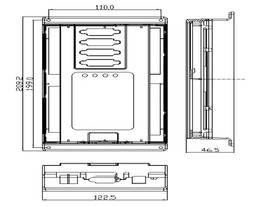
) Outer dimensions
http://www.adtechcn.com |
7 |
) Operating environment:
Power supply: DC 24V
Power consumption: 3.6W — 5.0W
Operating temperature: 45
Storage temperature: -40 — 55
Humidity: 40% — 80%
Storage humidity: 0% — 95%
) Application
zEngraving and milling machine
zSpray coater, welding machine
zFour-axis robot
http://www.adtechcn.com |
8 |

Chapter II Electric Wiring
)Illustration and definition for terminals
4.1Definition of JA port (0~16-path input)
http://www.adtechcn.com |
9 |
Line No. |
Name |
Definition |
|
1 |
INCOM1 |
Shared input 1 |
|
2 |
IN0 |
home position X |
|
3 |
IN1 |
Home position Y |
|
4 |
IN2 |
Home position |
Z |
5 |
IN3 |
Home position |
A |
6 |
IN4 |
X positive limit |
|
7 |
IN5 |
X negative limit |
|
8 |
IN6 |
Y positive limit |
|
9 |
IN7 |
Y negative limit |
|
10 |
IN8 |
Z positive limit |
|
11 |
IN9 |
Z negative limit |
|
12 |
IN10 |
A positive limit |
|
13 |
IN11 |
A negative limit |
|
14 |
IN12 |
Manual stop |
|
15 |
IN13 |
Manual return to home position |
|
16 |
IN14 |
Manually run the program for machining |
|
17 |
IN15 |
Regular input |
|
18 |
IN16 |
|
|
|
|
||
http://www.adtechcn.com |
10 |

4.2 Definition of JB port (17~33-path input)
.
Line No. |
Name |
Definition |
|
|
|
|
|
1 |
INCOM2 |
Shared input 2(please connect it to +12V~+24V power) |
|
2 |
IN17 |
|
|
|
|
|
|
3 |
IN18 |
|
|
|
|
|
|
4 |
IN19 |
|
|
|
|
|
|
5 |
IN20 |
|
|
|
|
|
|
6 |
IN21 |
|
|
|
|
|
|
7 |
IN22 |
|
|
|
|
|
|
8 |
IN23 |
|
|
|
|
|
|
9 |
IN24 |
Regular input 17 33 |
|
|
|
||
10 |
IN25 |
||
(Please notice its order by refereeing to the silk printing on |
|||
|
|
||
11 |
IN26 |
||
PCB) |
|||
|
|
||
12 |
IN27 |
||
|
|||
|
|
|
|
13 |
IN28 |
|
|
|
|
|
|
14 |
IN29 |
|
|
|
|
|
|
15 |
IN30 |
|
|
|
|
|
|
16 |
IN31 |
|
|
|
|
|
|
17 |
IN32 |
|
|
|
|
|
|
18 |
IN33 |
|
|
|
|
|
http://www.adtechcn.com |
11 |
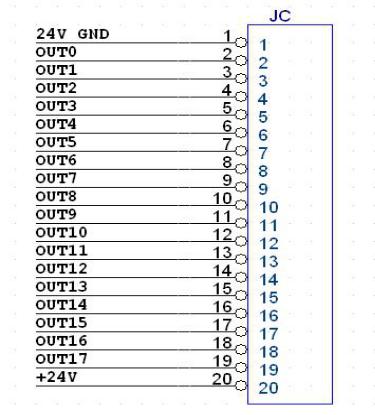
4.3 Definition of JC port (18-path input)
.
|
Line No. |
Name |
Definition |
|
|
|
|
|
|
|
1 |
24VGND |
Shared output |
|
|
|
|
|
|
|
2 |
OUT0 |
Regular 0 17 |
|
|
|
|
|
|
|
3 |
OUT1 |
|
|
|
|
|
|
|
|
4 |
OUT2 |
|
|
|
|
|
|
|
|
5 |
OUT3 |
|
|
|
|
|
|
|
|
6 |
OUT4 |
|
|
|
|
|
|
|
|
7 |
OUT5 |
|
|
|
|
|
|
|
|
8 |
OUT6 |
|
|
|
|
|
|
|
http://www.adtechcn.com |
|
12 |
||

9 |
OUT7 |
|
|
|
|
|
|
10 |
OUT8 |
|
|
|
|
|
|
11 |
OUT9 |
|
|
|
|
|
|
12 |
OUT10 |
|
|
|
|
|
|
13 |
OUT11 |
|
|
|
|
|
|
14 |
OUT12 |
|
|
|
|
|
|
15 |
OUT13 |
|
|
|
|
|
|
16 |
OUT14 |
|
|
|
|
|
|
17 |
OUT15 |
|
|
|
|
|
|
18 |
OUT16 |
|
|
|
|
|
|
19 |
OUT17 |
|
|
|
|
|
|
20 |
+24V |
+24V power input for loading (requiring external 12~+24 V |
|
power) |
|||
|
|
||
|
|
|
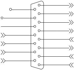
4.4 Definition of axis X’s port (axis X’s pulse and direction)
|
JCP1 |
|
|
PUCOM |
1 |
XPU+ |
|
EXT_VCCA |
9 |
|
|
2 |
XPU- |
||
|
|||
+24V |
10 |
||
|
|||
3 |
XDR+ |
||
|
|||
24VGND |
11 |
||
|
|
12 |
4 |
XDR- |
XECA+ |
|
||
5 |
|
||
|
XALARM |
||
|
13 |
||
XECA- |
|
||
6 |
|
||
|
OUT18 |
||
|
14 |
||
XECB+ |
|
||
7 |
|
||
|
XECZ+ |
||
|
15 |
||
XECB- |
|
||
8 |
|
||
|
XECZ- |
||
|
|
||
|
|
|
|
|
|
DB15 |
|
15-pin female jack (same as lathe and milling machine)
http://www.adtechcn.com |
13 |
Line No. |
Name |
Definition |
|
|
|
|
|
1 |
XPU+ |
Axis X’s pulse signal + |
|
|
|
|
|
2 |
XPU- |
Axis X’s pulse signal - |
|
|
|
|
|
3 |
XDR+ |
Axis X’s direction signal + |
|
|
|
|
|
4 |
XDR- |
Axis X’s direction signal - |
|
|
|
|
|
5 |
XALARM (IN34) |
Regular input signal, can be used as server alarm input of axis X |
|
|
|
|
|
6 |
OUT18 |
Regular input signal, can be used as server full capacity and other |
|
functions |
|||
|
|
||
|
|
|
|
7 |
XECZ+(IN38) |
Phase Z’s input + for axis X’s encoder |
|
|
|
|
|
8 |
XECZ-(IN38) |
Phase Z’s input - for axis X’s encoder |
|
|
|
|
|
9 |
EXT_VCCA |
Driver used for single-end input |
|
|
|
|
|
10 |
+24V |
24V power + (output to server) |
|
|
|
|
|
11 |
24VGND |
24V power - (output to server) |
|
|
|
|
|
12 |
XECA+(IN42) |
Phase A’s input + for axis X’s encoder |
|
|
|
|
|
13 |
XECA-(IN42) |
Phase A’s input - for axis X’s encoder |
|
|
|
|
|
14 |
XECB+(IN43) |
Phase B’s input + for axis X’s encoder |
|
|
|
|
|
15 |
XECB-(IN43) |
Phase B’s input - for axis X’s encoder |
|
|
|
|
4.5 Definition of axis Y’s port (axis Y’s pulse and direction)
http://www.adtechcn.com |
14 |
|
JCP2 |
|
|
PUCOM |
1 |
YPU+ |
|
EXT_VCCA |
9 |
|
|
2 |
YPU- |
||
|
|||
+24V |
10 |
||
|
|||
3 |
YDR+ |
||
|
|||
24VGND |
11 |
||
|
|
12 |
4 |
YDR- |
YECA+ |
|
||
5 |
|
||
|
YALARM |
||
|
13 |
||
YECA- |
|
||
6 |
|
||
|
OUT19 |
||
|
14 |
||
YECB+ |
|
||
7 |
|
||
|
YECZ+ |
||
|
15 |
||
YECB- |
|
||
8 |
|
||
|
YECZ- |
||
|
|
||
|
|
|
|
|
|
DB15 |
|
15-pin female jack (same as lathe and milling machine)
Line No. |
Name |
Definition |
|
|
|
|
|
1 |
YPU+ |
Axis Y’s pulse signal + |
|
|
|
|
|
2 |
YPU- |
Axis Y’s pulse signal - |
|
|
|
|
|
3 |
YDR+ |
Axis Y’s direction signal + |
|
|
|
|
|
4 |
YDR- |
Axis Y’s direction signal - |
|
|
|
|
|
5 |
YALARM (IN35) |
Regular input signal, can be used as server alarm input of axis Y |
|
|
|
|
|
6 |
OUT19 |
Regular input signal, can be used as server full capacity and other |
|
functions |
|||
|
|
||
|
|
|
|
7 |
YECZ+(IN39) |
Phase Z’s input + for axis Y’s encoder |
|
|
|
|
|
8 |
YECZ-(IN39) |
Phase Z’s input - for axis Y’s encoder |
|
|
|
|
|
9 |
EYT_VCCA |
Driver used for single-end input |
|
|
|
|
|
10 |
+24V |
24V power + (output to server) |
|
|
|
|
|
11 |
24VGND |
24V power - (output to server) |
|
|
|
|
|
12 |
YECA+(IN44) |
Phase A’s input + for axis Y’s encoder |
|
|
|
|
|
http://www.adtechcn.com |
15 |
||
13 |
YECA-(IN44) |
Phase A’s input - for axis Y’s encoder |
|
|
|
14 |
YECB+(IN45) |
Phase B’s input + for axis Y’s encoder |
|
|
|
15 |
YECB-(IN45) |
Phase B’s input - for axis Y’s encoder |
|
|
|
4.6 Definition of axis Z’s port (axis Z’s pulse and direction)
|
JCP3 |
|
PUCOM |
1 |
ZPU+ |
EXT_VCCB |
9 |
|
|
10 |
2 |
ZPU- |
+24V |
|
||
3 |
|
||
|
ZDR+ |
||
|
11 |
||
|
|
||
|
4 |
|
|
|
12 |
ZDR- |
|
ZECA+ |
|
||
5 |
|
||
|
ZALARM |
||
|
13 |
||
ZECA- |
|
||
6 |
|
||
|
OUT20 |
||
|
14 |
||
ZECB+ |
|
||
7 |
|
||
|
ZECZ+ |
||
|
15 |
||
ZECB- |
|
||
8 |
|
||
|
ZECZ- |
||
|
|
||
|
|
|
|
|
|
DB15 |
|
15-pin female jack (same as lathe and milling machine)
.
Line No. |
Name |
Definition |
|
|
|
|
|
1 |
ZPU+ |
Axis Z’s pulse signal + |
|
|
|
|
|
2 |
ZPU- |
Axis Z’s pulse signal - |
|
|
|
|
|
3 |
ZDR+ |
Axis Z’s direction signal + |
|
|
|
|
|
4 |
ZDR- |
Axis Z’s direction signal - |
|
|
|
|
|
5 |
ZALARM (IN36) |
Regular input signal, can be used as server alarm input of axis Z |
|
|
|
|
|
6 |
OUT20 |
Regular input signal, can be used as server full capacity and other |
|
functions |
|||
|
|
||
|
|
|
|
http://www.adtechcn.com |
16 |
||
7 |
ZECZ+(IN40) |
Phase Z’s input + for axis Z’s encoder |
|
|
|
8 |
ZECZ-(IN40) |
Phase Z’s input - for axis Z’s encoder |
|
|
|
9 |
EZT_VCCA |
Driver used for single-end input |
|
|
|
10 |
+24V |
24V power + (output to server) |
|
|
|
11 |
24VGND |
24V power - (output to server) |
|
|
|
12 |
ZECA+(IN46) |
Phase A’s input + for axis Z’s encoder |
|
|
|
13 |
ZECA-(IN46) |
Phase A’s input - for axis Z’s encoder |
|
|
|
14 |
ZECB+(IN47) |
Phase B’s input + for axis Z’s encoder |
|
|
|
15 |
ZECB-(IN47) |
Phase B’s input - for axis Z’s encoder |
|
|
|
4.7 Definition of axis A’s port (axis A’s pulse and direction)
|
JCP4 |
|
|
PUCOM |
1 |
APU+ |
|
EXT_VCCB |
9 |
|
|
2 |
APU- |
||
|
|||
+24V |
10 |
||
|
|||
3 |
ADR+ |
||
24VGND |
|||
11 |
|||
|
|
12 |
4 |
ADR- |
AECA+ |
|
||
5 |
|
||
|
AALARM |
||
|
13 |
||
AECA- |
|
||
6 |
|
||
|
OUT21 |
||
|
14 |
||
AECB+ |
|
||
7 |
|
||
|
AECZ+ |
||
|
15 |
||
AECB- |
|
||
8 |
|
||
|
AECZ- |
||
|
|
||
|
|
|
|
|
|
DB15 |
|
15-pin female jack (same as lathe and milling machine)
.
Line No. |
|
Name |
Definition |
|
|
|
|
1 |
|
APU+ |
Axis A’s pulse signal + |
|
|
|
|
http://www.adtechcn.com |
|
17 |
|
2 |
APU- |
Axis A’s pulse signal - |
|
|
|
|
|
3 |
ADR+ |
Axis As direction signal + |
|
|
|
|
|
4 |
ADR- |
Axis A’s direction signal - |
|
|
|
|
|
5 |
AALARM (IN37) |
Regular input signal, can be used as server alarm input of axis A |
|
|
|
|
|
6 |
OUT21 |
Regular input signal, can be used as server full capacity and other |
|
functions |
|||
|
|
||
|
|
|
|
7 |
AECZ+(IN41) |
Phase Z’s input + for axis A’s encoder |
|
|
|
|
|
8 |
AECZ-(IN41) |
Phase Z’s input - for axis A’s encoder |
|
|
|
|
|
9 |
EAT_VCCA |
Driver used for single-end input |
|
|
|
|
|
10 |
+24V |
24V power + (output to server) |
|
|
|
|
|
11 |
24VGND |
24V power - (output to server) |
|
|
|
|
|
12 |
AECA+(IN48) |
Phase A’s input + for axis A’s encoder |
|
|
|
|
|
13 |
AECA-(IN48) |
Phase A’s input - for axis A’s encoder |
|
|
|
|
|
14 |
AECB+(IN49) |
Phase B’s input + for axis A’s encoder |
|
|
|
|
|
15 |
AECB-(IN49) |
Phase B’s input - for axis A’s encoder |
|
|
|
|
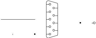
4.8 SI 0 (serial interface 0)
|
|
|
|
|
|
|
1 |
JCP5 |
|
|||
|
|
|
|
|
|
|
6 |
|
|
|
||
|
|
TX0 |
2 |
|
|
|
||||||
|
|
|
7 |
|
|
|
||||||
|
|
RX0 |
|
3 |
|
|
|
|||||
|
|
|
8 |
|
|
VDD50 |
||||||
|
|
|
|
|
|
4 |
|
|
||||
|
|
|
|
|
|
9 |
|
|
||||
|
|
|
|
|
|
|
|
|
||||
|
|
|
|
|
|
|
5 |
|
|
|
||
|
|
|
|
|
|
|
|
|
|
|
|
|
|
|
|
|
|
|
|
|
|
|
|
|
|
|
|
|
|
|
|
|
Male jack DB9 |
|
||||
|
|
|
|
|
|
|
|
|||||
|
|
|
|
|
|
|
|
|
||||
Line No. |
|
Name |
|
|
|
|
Definition |
|
||||
|
|
|
|
|
||||||||
1 |
|
NC |
Not connected |
|
||||||||
|
|
|
|
|
||||||||
2 |
|
TX0 |
Transmit data |
|
||||||||
|
|
|
|
|
||||||||
3 |
|
RX0 |
Receive data |
|
||||||||
|
|
|
|
|
||||||||
4 |
|
GND |
Power’s grounding |
|
||||||||
|
|
|
|
|
||||||||
5 |
|
GND |
Power’s grounding |
|
||||||||
|
|
|
|
|
||||||||
6 |
|
NC |
Not connected |
|
||||||||
|
|
|
|
|
||||||||
7 |
|
VDD5.0 |
Provide 5V power to external devices |
|
||||||||
|
|
|
|
|
||||||||
8 |
|
VDD5.0 |
Provide 5V power to external devices |
|
||||||||
|
|
|
|
|
||||||||
9 |
|
NC |
Not connected |
|
||||||||
|
|
|
|
|
|
|
|
|
|
|
|
|
SI 0 is normally used for displaying the information of running during network configuration and debugging.
http://www.adtechcn.com |
18 |
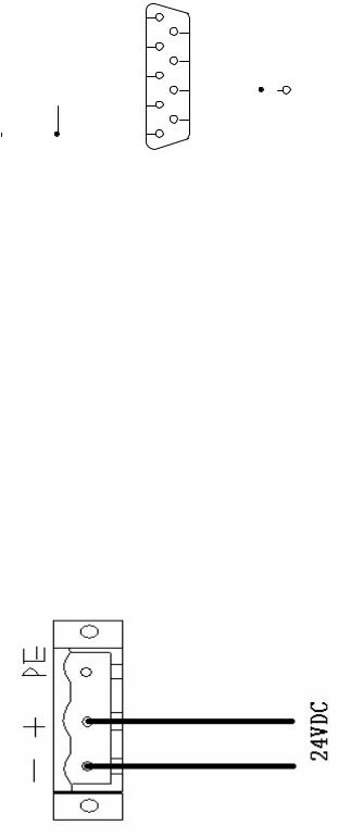
4.9 SI 1 (serial interface 1)
|
|
|
|
|
|
1 |
JCP6 |
|
|||
|
|
|
|
|
|
|
6 |
|
|
|
|
|
|
|
|
|
TX1 |
2 |
|
|
|
||
|
|
|
|
|
|
7 |
|
|
|
||
|
|
|
|
|
RX1 |
3 |
|
|
|
||
|
|
|
|
|
|
8 |
|
|
VDD50 |
||
|
|
|
|
|
|
4 |
|
|
|||
|
|
|
|
|
|
9 |
|
|
|||
|
|
|
|
|
|
|
|
|
|||
|
|
|
|
|
|
5 |
|
|
|
||
|
|
|
|
|
|
|
|
|
|
|
|
|
|
|
|
|
|
|
|||||
|
|
|
|
|
|
|
|||||
|
|
|
|
|
|
Female jack DB9 |
|
||||
|
|
|
|
|
|
|
|||||
|
|
|
|
|
|
|
|||||
|
|
|
|
|
|
|
|||||
Line No. |
Name |
|
|
|
|
Definition |
|||||
|
|
|
|
||||||||
1 |
NC |
Not connected |
|
||||||||
|
|
|
|
||||||||
2 |
TX1 |
Transmit data |
|
||||||||
|
|
|
|
||||||||
3 |
RX1 |
Receive data |
|
||||||||
|
|
|
|
||||||||
4 |
GND |
Power’s grounding |
|
||||||||
|
|
|
|
||||||||
5 |
GND |
Power’s grounding |
|
||||||||
|
|
|
|
||||||||
6 |
NC |
Not connected |
|
||||||||
|
|
|
|
||||||||
7 |
VDD5.0 |
Provide 5V power to external devices |
|
||||||||
|
|
|
|
||||||||
8 |
VDD5.0 |
Provide 5V power to external devices |
|
||||||||
|
|
|
|
||||||||
9 |
NC |
Not connected |
|
||||||||
|
|
|
|
|
|
|
|
|
|
|
|
SI 1 not used
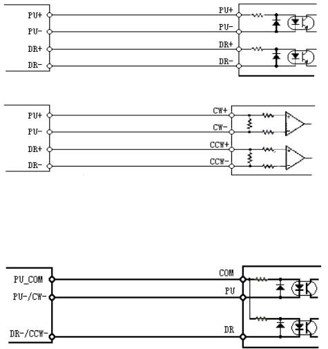
) Connecting to power supply
The mainboard of this device employs +24 VDC as its power source, which should be supplied from the external switching power. The wiring for the power supply is shown in the figure below:
http://www.adtechcn.com |
19 |
) Standard USB interface (USB)
) Standard Ethernet interface (RJ45)
When the host is directly connected to the Control Card, crossover cables will be used for the connection. In other words, one end of the wires adopts standard 568B line order, and the other 568A line order.
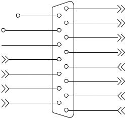
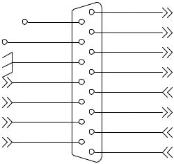
) Connection for input signal
Optical coupler input
The INCOM terminal should be connected to the positive pole of the external power source and the input signal to the corresponding pin.
Among the terminals, the shared terminal of IN0—IN16 is INCOM1; the shared terminal of IN17—IN33 INCOM2. When in use, the shared terminal should be connected to +24V power source. For the input terminals, the lower level is effective. The current of single-path input should not be over 15mA, but not less than 5mA.
http://www.adtechcn.com |
20 |
) Connection for pulse output signal
1. Differential mode:
This mode is suitable for the stepping driver and most of the server drivers with independent pulse and direction input. It is recommended this mode is used, for it provides high anti-interference capacity.
Driver of stepping motor
Driver of server motor
2. Single-end mode
This mode was used for the stepping motors, with which the anodes of pulse and direction were connected together in early time.
Driver of stepping motor
Note: It is not suitable for stepping motors, the cathodes of whose pulse and direction are connected together.
EXTVCC5.0A or EXTVCC5.0B is not used for other purposes except for the non-differential connection method of the driver’s pulse. Otherwise, the internal circuit of the ADT-8840 might be damaged. Any two of the four pins, namely, PU+, PU-, DR+ and DRshall never be connected together. Otherwise, the internal circuit of the ADT-8840 might be damaged too.
http://www.adtechcn.com |
21 |
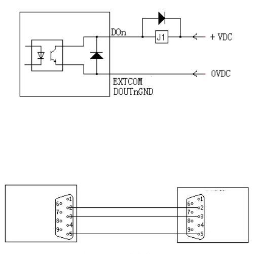
) Connection for output signal
The switch value of this control system is output through the open collector, with JC1 as both the shared terminal and GND of the loaded power source. In actual use, the operator should connect the Pin 20 of JCI to +24V, and the output point is enabled at low level. The load should be connected to somewhere between +24V and the output point. The internal output circuit is safeguarded by mechanisms of over-current protection, over-voltage protection, short circuit protection, overheat protection and follow-current protection. However, if an external sensible load is connected, like the relay, you should connect a follow-current diode at the two ends of the relay, as shown in the figure below:
or
Note: Recommended voltage: < 24V (preferably not over 30V). Never reversely connect the negative and positive poles, nor allow the load to have short circuit. Otherwise, the module might be damaged.
) Connection for communication signal
PC
Control Card
Communication mode RS232
http://www.adtechcn.com |
22 |
Chapter III System Functions
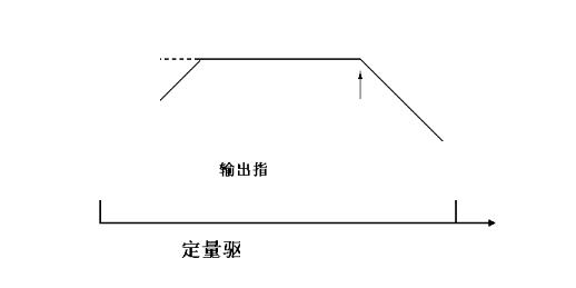
) Preset drive
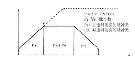
“Preset drive” means pulses of a set number are output with a fixed velocity or acceleration/deceleration. This function is performed when the tool needs to move to a specific position or execute a specific action. The mechanism of preset drive for acceleration/deceleration is shown in the figure below. When the number of remaining pulses is smaller than that of accumulated pulses, the system will begin to decelerate, and terminate its drive once the output of designated pulses is completed.
To perform preset drive for acceleration/deceleration, the following parameters should be set:
a)Range: R;
b)Acceleration/deceleration: A/D;
c)Start velocity: SV;
d)Drive velocity: V;
e)Output pulse number: P
Velocity
Drive velocity
Start velocity
Automatic deceleration
Stop when the output of designated pulses is completed
Time
Preset drive
When preset drive for acceleration/deceleration is engaged, the system will start automatic deceleration at the computed point as shown in the above figure.
http://www.adtechcn.com |
23 |
) Continuous drive
In continuous drive mode, the output of drive pulses will keep going till the stop commands of high position or external stop signal is enabled. This function can be performed when home position search, scanning or control of motor speed is needed.
) Velocity curve
The drive pulses of each axis are output through the preset drive commands with positive/negative direction or through the continuous drive commands. And the velocity curves of preset speed, linear acceleration/deceleration and S-shape acceleration/deceleration can be generated through mode or parameter setting.
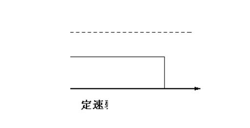
) Set-speed drive
“Set-speed drive” means drive pulses are output with an unchanged speed. If the set drive velocity is lower than the start velocity, there will be no acceleration/deceleration drive, but set-speed drive. When signals for home position search, encoder’s phase Z and the like are used, if the system needs to stop immediately after the signal is found, the system can perform set-speed drive at a low velocity value from the very beginning, without the need of acceleration/deceleration drive.
To perform Set-speed drive, the following parameters should be set:
zRange: R;
zStart velocity: SV;
zDrive velocity: V.
Velocity
SV
V
Time
Set-speed drive
http://www.adtechcn.com |
24 |
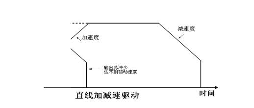
Linear acceleration/deceleration drive
“Linear acceleration/deceleration drive” means the system accelerate to the set drive velocity from start velocity in a linear fashion.
In Set-speed mode, the acceleration counter counts the number of pulses accumulated during the acceleration process. When the number of remaining pulses is smaller than that of accumulated pulses, the system will begin to decelerate (automatically). In deceleration, the velocity will be lowered to the start value in a linear fashion.
To perform linear acceleration/deceleration drive, the following parameters should be set:
zRange: R;
zAcceleration: A; acceleration/deceleration;
zDeceleration: D; individually set deceleration (subject to temporary setting);
zStart velocity: SV;
zDrive velocity: V;
zOutput pulse number: P, for preset drive (subject to temporary setting)
Velocity
D |
|
|
|
|
|
|
||
|
|
|
|
|
D |
|
||
|
|
|
|
|
|
|
||
|
|
|
|
|
|
|
|
|
|
|
A |
|
|
|
|
|
|
SV |
|
|
|
|
|
|
|
|
|
|
|
|
|
|
|
|
|
|
|
To small number of output pulse to |
|
|
|
|||
|
|
|
reach the drive velocity |
|
|
|
||
|
|
|
|
|
|
|
|
|
|
Linear acceleration/deceleration drive |
|
Time |
|||||
|
|
|
|
|
|
|
|
|
Triangle prevention for preset drive
In preset drive mode with linear acceleration and deceleration, if the number of output pulses is smaller than that needed to reach the drive speed through acceleration, a triangle-shape wave will be generated. At the time, the triangle prevention function will be activated.
Triangle prevention function means, in preset drive mode with linear acceleration and deceleration, even if the number of output pulse is smaller than needed, the system will stop acceleration and maintain the unchanged velocity after the number of pulses consumed during acceleration and deceleration is greater than 1.5 times of the total number of output pulses. Therefore, even when the number of output pulse is smaller than one half of that of output pulses, the motion will be within the Set-speed domain.
http://www.adtechcn.com |
25 |
Velocity
Acceleration stops |
|
Number of output pulses |
|
|
Number of pulses consumed |
|
during acceleration |
|
|
Time
Triangle prevention for linear acceleration and deceleration
) Speed mode
The speed mode of ADT-8840 falls into two categories, namely, self-define mode and set-speed mode. The former is the default value in the system, while the latter can be set through the function “adt8840a_set_speed_mode()” at the upper PC.
The self-define mode means the user can set the function and change the motion velocity, SV and acceleration through the motion parameters. In this mode, the data can be changed at any time and will not be saved in the system configuration files of ADT-8840. The unit of velocity parameters in this mode can be either pulse or millimeter. A speed in millimeter is a figure converted on the basis of the equivalent pulses. The default pulse equivalent of the four axes is 320p/mm.
The set-speed mode means the user can set the speed mode as a fixed value through the function “adt8840a_set_speed_mode()” after the operation velocity parameters are properly set. The set velocity parameters will be saved in system configuration files of ADT-8840 and used as correct and fixed data on motion for some other machining operations. In set-speed mode, the functions for setting the motion parameters will be disabled, except the G code and the follow-up velocity in the interpolation commands of hardware buffer.
) Buffer mode
In upper PC, the software buffer machining mode or immediate execution mode can be activated through the
function “adt8840a_set_buff_mode()”.
The software buffer machining mode means the user can save the motion commands or IO operation commands in the buffer of ADT-8840, with which ADT-8840 can also transmit the commands during the motion in a real-time manner. This mode can ensure the continuity of machining. With 512 commands on machining at maximum, the buffer works in such a way that the commands in it flows on a first-in-first-out basis. In other words, the executed commands will be deleted from the buffer, and the remaining space is added by 1 after the deletion. When the user
http://www.adtechcn.com |
26 |
downloads the commands from the buffer by batches, it must know the remaining space in the buffer through the query command “adt8840a_get_buff_depth ”, so as to avoid the overflow of software cache. In this mode, only when the current command is fully executed, can the next command be executed. When this mode is enabled, if any hardware buffer commands are downloaded into the control card while the non-hardware buffer commands are being executed, the hardware buffer commands will also be saved in the software buffer. Once all non-hardware buffer commands are executed, the hardware buffer commands will be saved in the hardware buffer. Please note that the hardware buffer commands accumulated in the software buffer should not exceed the capacity of the hardware buffer.
The immediate execution mode refers to a machining method used when the buffer is closed. In this mode, the user can only transmit the commands in the way the single command is executed. In other words, when the control card is executing the motion commands, the user must judge at the upper PC whether the current motion is completed. Only when the completion of motion is detected, can the next command be executed. Otherwise, the motion state might become confused.
In addition to the software buffer mode, ADT-8840 also provides some interpolation functions with hardware
buffer, such as: adt8840a_fifo_inp_move1(), adt8840a_fifo_inp_move2(), adt8840a_fifo_inp_move3(), adt8840a_fifo_inp_move4(),
Details on interpolation of hardware buffer will be provided in the follow-up chapters of this Manual.
) Position management
Logic-position counter and actual-position counter
The logic-position counter counts the number of pulses based on the positive/negative direction output. In other words, it counts “1” upward when one positive pulse is output, and “1” downward when one negative pulse is output.
The actual-position counter counts the pulses coming from the external encoder. The user can use the commands to select the pulse type as phase A/B signal or independent 2 pulses of upward/downward counted signals. The counting direction can be set.
The data of the two counters can be written and read at any time, whose counting ranges between -2,147,483,648 +2,147,483,647.
http://www.adtechcn.com |
27 |
Two-phase pulse input mode |
|
Count upward |
Count downward |
Up/down pulse input mode
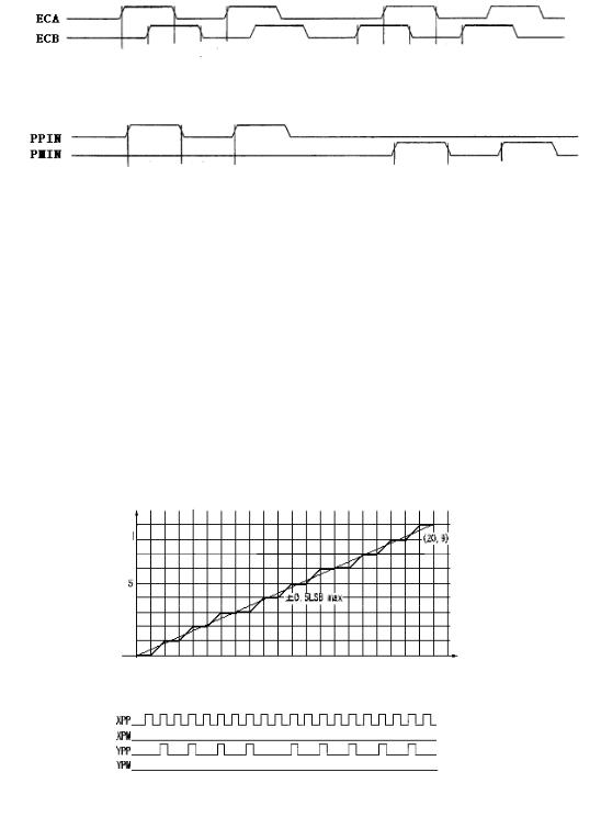
) Interpolation
The controller can perform the linear interpolation for any 2-4 axes.
During the interpolation process, the interpolation computation is carried out under the pulse’s basic time order of the designated axis X. Therefore, such parameters as the designated axis X’s start velocity and drive velocity should be set before the interpolation command is executed.
Linear interpolation for 2-4 axes
After the end-point coordinates relative to the current position are set, the system will begin to perform the linear interpolation. The coordinates of linear interpolation is within a scope of 24-digit character with symbol.
The interpolation ranges from the current position of the axis to somewhere between -8,388,607 and +8,388,607.
Minor axis
Major axis
Position precision of linear interpolation
Minor axis
Major axis
Example of drive pulse output at the endpoint X:20, Y:9
As shown in the figure above, within the whole interpolation scope, the position precision for the designated line is ±0.5LSB. The figure also shows the example of drive pulse output for linear interpolation. Among the set values of endpoint, the one with the greatest absolute value comes from the major axis, which keeps outputting pulse during the interpolation drive, while others are minor axes. Depending on the results of interpolation arithmetic, sometimes the pulses are output, sometimes not.
http://www.adtechcn.com |
28 |
Hardware buffer interpolation
As for the control card without the hardware interpolation function, if the next interpolation is needed after the previous one is ended, it can only inquire whether the previous interpolation is finished so that the next data of the next interpolation can be output. If the upper PC runs slowly, or a multipurpose operating system runs in the upper computer, there will be pause between the two interpolations, which not only affects the effects of interpolation, but also makes it hard to raise the interpolation speed.
With the hardware buffer interpolation in ADT-8840, this problem can be properly solved, for a great number of interpolation commands can be continuously saved in the space of hardware buffer. Even if the system is executing an interpolation command for motion, an interpolation command can be written.
When a command is written into an empty hardware buffer, the control card will immediately execute the first written command on a first-in-first-out basis. The system will stop once the execution of the current interpolation command is completed at the time the hardware buffer is empty. The user should judge whether the buffer space is full when saving the interpolation commands into it. If it is full, no more command can be written. Otherwise, the commands might be lost.
With hardware buffer interpolation, the pause between two interpolations can be effectively avoided. Even if the computer runs slowly, good effects can be obtained.
Note:
1.When a hardware buffer interpolation command is being executed, if the interpolation motion needs to be stopped immediately, the operator must first clear the buffer and then stop the motion.
2.When a hardware buffer interpolation command is being executed, no other motion command should be executed simultaneously. Otherwise, motion confusion will arise.
3.Interpolation buffer only works in even speed state, not in acceleration and deceleration state.
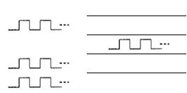
) Pulse output mode
As shown in the table below, two modes are available for the drive output pulses. In independent 2 pulse output mode, drive pulses are output from PU/CW when it is a positive direction drive, and from DR/CCW when negative. In 1 pulse output mode, drive pulses are output from PU/CW and direction signals are output from DR/CCW.
When positive logic setting is available for pulse/direction
Pulse output mode |
Drive direction |
Wave shape of output signal |
||
|
|
|||
PU/CW Signal |
DR/CCW Signal |
|||
|
|
|||
|
|
|
Low Level |
|
Independent 2 pulse |
+direction drive output |
|
||
output mode |
|
|
|
|
-direction drive output |
Low Level |
|
||
|
|
|
Low Level |
|
1 pulse output mode |
+direction drive output |
|
||
|
|
|
||
-direction drive output |
|
High Level |
||
|
|
|||
|
|
|
|
|
29
 Loading...