


ADTECH 4 SERIES
CNC MAINTAINANCE USER MANUAL
1

|
|
ADTECH 4 series CNC System (maintainance Manual) |
|
|
|
|
|
Contents |
|
||
1. Foreword ..................................................................................................................................... |
3 |
||
2.System technical characteristics................................................................................................... |
3 |
||
2.1 |
System technical parameters .................................................................................................................. |
3 |
|
2.3 |
System function...................................................................................................................................... |
5 |
|
|
2.3.1 Self-diagnosis......................................................................................................................................................... |
5 |
|
|
2.3.2 Compensation ........................................................................................................................................................ |
5 |
|
|
2.3.3 Abundant instruction system .................................................................................................................................. |
5 |
|
|
2.3.4 Full English menu operation & full screen edit...................................................................................................... |
6 |
|
|
2.3.5 Abundant error-correction functions ...................................................................................................................... |
6 |
|
|
2.3.6 Program exchange between CNC system and PC .................................................................................................. |
6 |
|
2.4 |
System operating condition .................................................................................................................... |
6 |
|
3. Operation panel ........................................................................................................................... |
7 |
||
3.1 |
LCD/keypad ........................................................................................................................................... |
7 |
|
3.2 |
LCD brightness adjustment .................................................................................................................... |
8 |
|
3.3 |
System menus......................................................................................................................................... |
8 |
|
3.4 |
Operating keys...................................................................................................................................... |
10 |
|
4.Manual operation........................................................................................................................ |
11 |
||
4.1 |
Returning to home point manually ........................................................................................................ |
11 |
|
4.2 |
JOG Function ....................................................................................................................................... |
13 |
|
4.3 |
Single step ............................................................................................................................................ |
13 |
|
4.4MPG ...................................................................................................................................................... |
13 |
||
4.5 |
Manual auxiliary function operation .................................................................................................... |
14 |
|
4.6 Tool setting ........................................................................................................................................... |
15 |
||
|
4.6.2 tool setting gauge ................................................................................................................................................. |
17 |
|
4.7 |
Data settings ......................................................................................................................................... |
18 |
|
|
4.7.1 Tool compensation setting.................................................................................................................................... |
18 |
|
|
4.7.2 System parameter setting ..................................................................................................................................... |
19 |
|
4.8 |
System shoutcut key operation............................................................................................................. |
19 |
|
5.Automatic operation ................................................................................................................... |
20 |
||
5.1 |
Memory operation ................................................................................................................................ |
20 |
|
5.2 |
MDI operation ...................................................................................................................................... |
20 |
|
5.3 |
USB disk(flash drive) DNC ................................................................................................................. |
20 |
|
5.4 |
Speed rate adjustment........................................................................................................................... |
21 |
|
5.5 |
Run idle ................................................................................................................................................ |
21 |
|
5.6 |
SBK function........................................................................................................................................ |
21 |
|
|
|
|
|
|
|
|
|
|
2 |
|
|

|
|
ADTECH 4 series CNC System (maintainance Manual) |
|
|
|
|
|
5.7 |
BDT function........................................................................................................................................ |
22 |
|
5.8 |
Stopping automatic operating............................................................................................................... |
22 |
|
6.Safe operation............................................................................................................................. |
23 |
||
6.1 |
Emergency stop .................................................................................................................................... |
23 |
|
6.2 |
Hard limit over travel ........................................................................................................................... |
23 |
|
6.3 |
Soft limit over travel ............................................................................................................................ |
23 |
|
7. Alarm and selfdiagnosis function............................................................................................ |
24 |
||
7.1 |
NC program execution alarm ............................................................................................................... |
24 |
|
7.2 |
System environment alarm ................................................................................................................... |
25 |
|
7.3 Alarm processing.................................................................................................................................. |
27 |
||
7.4 |
Self-diagnosis function......................................................................................................................... |
27 |
|
8.Program saving & editing .......................................................................................................... |
28 |
||
8.1 |
Saving the program to the memory ...................................................................................................... |
28 |
|
|
8.1.1 Keypad input (new program) ............................................................................................................................... |
28 |
|
|
8.1.2 PC serial port input .............................................................................................................................................. |
28 |
|
|
8.1.3 Copy program from USB disk ............................................................................................................................. |
28 |
|
8.2 |
Reading programs into work area......................................................................................................... |
29 |
|
|
8.2.1 Reading programs from controller into work area ............................................................................................... |
29 |
|
|
8.2.2 Reading programs from USB disk into work area ............................................................................................... |
29 |
|
8.3 |
Editing & modifying programs ............................................................................................................ |
29 |
|
8.4 |
Deleting files ........................................................................................................................................ |
29 |
|
|
8.4.1 Deleting files in memory...................................................................................................................................... |
29 |
|
9 Main interfaces of the controller ................................................................................................ |
31 |
||
9.1 |
Position interface.................................................................................................................................. |
31 |
|
9.2 |
Edit interface ........................................................................................................................................ |
33 |
|
9.3 |
MDI interface ....................................................................................................................................... |
34 |
|
9.4 |
File management .................................................................................................................................. |
35 |
|
9.5 |
Graph simulation .................................................................................................................................. |
36 |
|
9.6 |
Parameter interface............................................................................................................................... |
37 |
|
9.7 |
Compensation interface........................................................................................................................ |
40 |
|
9.8 workpiece coordinate system setting interface..................................................................................... |
41 |
||
9.9 |
Controller diagnosis interface (DGNOS) ............................................................................................. |
44 |
|
9.10 Macro variable view interface (macro variable)................................................................................. |
44 |
||
9.11 Current modal instruction info ........................................................................................................... |
45 |
||
10.System maintenance ................................................................................................................. |
46 |
||
10.1 Retoot ................................................................................................................................................. |
46 |
||
|
|
|
|
|
|
|
|
|
3 |
|
|

|
ADTECH 4 series CNC System (maintainance Manual) |
|
10.2 System upgrade .................................................................................................................................. |
46 |
|
10.3 Reset parameters to default value....................................................................................................... |
46 |
|
10.4 Parameter backup and recover ........................................................................................................... |
46 |
|
10.5 Entering BIOS .................................................................................................................................... |
47 |
|
11.System parameters.................................................................................................................... |
48 |
|
11.1 Parameter index list ............................................................................................................................ |
49 |
|
11.2 Genal parameters (P1.) ....................................................................................................................... |
63 |
|
11.3 Axis parameter configuration (P2.) .................................................................................................... |
74 |
|
11.4 Management parameters (P3.)............................................................................................................ |
90 |
|
11.5 Tool magazine parameters (P4.) ......................................................................................................... |
96 |
|
11.6 spindle parameters (P5.) ..................................................................................................................... |
96 |
|
11.7 Port configuration (P6.) .................................................................................................................... |
101 |
|
12 interface definition and connection ........................................................................................ |
104 |
|
12.1 Interface definition ........................................................................................................................... |
104 |
|
12.1.1. |
49 series controller interface ....................................................................................................................... |
104 |
12.1.2. 49serise Mounting dimensions........................................................................................................................ |
105 |
|
12.1.3. Installation precautions ................................................................................................................................... |
106 |
|
12.2 Port definition................................................................................................................................... |
107 |
|
12.2.2 Input port(XS7)................................................................................................................................................ |
110 |
|
12.2.3 |
Output port (XS8)......................................................................................................................................... |
112 |
12.2.4 |
MPG port...................................................................................................................................................... |
115 |
12.2.5 |
Spindle port .................................................................................................................................................. |
116 |
12.2.6 |
RS232 port definition ................................................................................................................................... |
118 |
12.2.7 USB memory (flash drive) port ---XS10 ...................................................................................................... |
118 |
|
12.2.8 |
PC USB port ---XS11................................................................................................................................... |
118 |
12.3 Electrical connection diagram ........................................................................................................... |
119 |
|
12.3.1 Electrical Symbol............................................................................................................................................. |
119 |
|
12.3.2 Main Power connection diagram...................................................................................................................... |
120 |
|
12.3.3 Servo drive connection diagram....................................................................................................................... |
121 |
|
12.3.4 Step connection diagram .................................................................................................................................. |
122 |
|
12.3.5 ADT9163 PCB board ....................................................................................................................................... |
123 |
|
13 how to load program (CNC OR NC file )........................................................................................ |
130 |
|
14 how to upgrade software................................................................................................................... |
133 |
|
15 ATC Function..................................................................................................................................... |
135 |
|
4

Basic Information
This Manual is written by Adtech (Shenzhen) Technology Co., Ltd. This Manual is edit by: Xue Zhen Yan
This Manual was first released on 27th Aug, 2013, version No. A0101 and item number BZ001B092A
Copyright Notice
The property rights of all the parts of the manual belong to Adtech (Shenzhen) Technology Co., Ltd. (Adtech for short), and any form of imitation, copying, transcription or translation by any company or individual without the permission is prohibited. This manual does not include any form of assurance, standpoint expression, or other intimations. Adtech and the stuffs have no responsibility for any direct or indirect disclosure of the information, benefit loss or business termination of this manual of the quoted product information. In addition, the product and the information mentioned in this manual are for reference only, and the content is subject to change without notice.
ALL RIGHTS RESERVED!
Adtech (Shenzhen) Technology Co., Ltd.
1

ADTECH 4 series CNC System (maintainance Manual)
Precautions and Explanations
Transport and storage:
Do not stack product package more than six layers;
Do not climb, stand on or place heavy stuff on the product package;
Do not pull the cable still connecting with machine to move product.
Forbid impact and scratch on the panel and display;
Prevent the product package from humidity, sun exposure,and rain.
Open-box inspection:
Open the package to confirm the product to be purchased by you.
Check damages situation after transportation;
Confirm the integrity of parts comparing with the parts list or damages situation;
Contact our company promptly for discrepant models, shortage accessories, or transport damages.
Wiring
Ensure the persons involved into wiring and inspecting are specialized staff;
Guarantee the product is grounded with less than 4Ω grounding resistance. Do not use neutral line (N) to substitute earth wire.
Ensure grounding to be correct and solid, in order to avoid product failures or unexpected consequences;
Connect the surge absorption diodes to the product in the required direction, otherwise, the product will be damaged;
Ensure the power switch is OFF before inserting or removing plug,or disassembling chassis.
Overhauling
Ensure the power is OFF before overhauling or components replacement;
Make sure to check failures after short circuit or overloading, and then reboot the machine after troubleshooting
Do not allow to frequently connect and disconnect the power, and at least one minute interval between power-on and power-off.
others
Do not open housing without permit;
Keep power OFF if not in use for a long time;
Pay close attention to keep dust and ferrous powder away from control;
Fix freewheel diode on relay coil in parallel if non-solid state relay is used as output relay. Check whether power supply meets the requirement to ensure not burning the control.
Install cooling fan if processing field is in high temperature, due to close relationship between service life of the control and environmental temperature. Keep proper operative temperature range for the control: 0 ~ 60 .
Avoid to use the product in the overheating, humid, dusty, or corrosive environments;
Add rubber rails as cushion on the place with strong vibration.
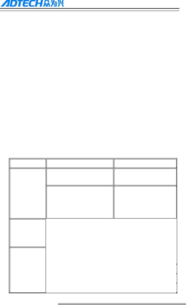
Maintenance:
Please implement routine inspection and regular check upon the following items, under the General usage conditions (i.e. environmental condition: daily average 30 , load rate: 80%, and operating rate: 12 hours/ day)
|
|
● Confirm environmental temperature, humidity, dust, or |
|
Routine Inspection |
Routine |
foreign objects. |
|
● Confirm abnormal vibration and noise; |
|||
|
|
||
|
|
● Check whether vents are blocked by yarn etc. |
|
|
|
|
|
Regular Check |
One year |
● Check whether solid components are loose |
|
● Confirm whether terminal block is damaged |
|||
|
|
||
|
|
|
2
ADTECH 4 series CNC System (maintainance Manual)
1. Foreword
CNC49 series cnc controllert developed by Adtech (Shenzhen) CNC Technology Co., Ltd. for milling machines and machining centers, CNC4940 is four axis motion controller and CNC4960 is six axis motion controller.
Instructions and reading convention of the Manual
Before using this CNC system, please read this Manual carefully to operate properly. Terminology note and reading convention in this Manual:
CNC4940 and CNC4960 are the controller with different axis and same hardware.
―CNC system‖, ―NC controller‖ and ―CNC49XX‖ mentioned in this Manual all refer to CNC4940/4960
The articles marked with ―Caution‖ prompt users to pay special attention for operation or setting, or else this operation may fail or certain action can‘t be performed.
2.System technical characteristics
2.1 System technical parameters
Function
Control axis
Input instruction
Feeding
Name
Control axis
Simultaneous control axes
Specification
4 axes (CNC4940 series)
6 axes (CNC4920 series)
4 axis linear interpolation (CNC4940 series)
6 axis linear interpolation (CNC4960 series)
Minimum setting unit |
|
0.001mm |
||
|
|
|
|
|
|
|
|
|
|
Minimum moving unit |
|
0.001mm |
||
|
|
|
|
|
|
|
|
|
|
Maximum instruction value |
|
±9999.999mm |
||
|
|
|
|
|
|
|
|
|
|
|
|
|
|
X axis, Y axis, Z axis, A axis: B axis, C |
Fast feeding speed |
|
|
||
|
|
|
|
axis 9999 mm/min (maximum) |
|
|
|
|
|
|
|
|
|
|
|
|
Per minute |
|
1~9999mm/min |
Feeding speed range |
|
|
|
|
|
|
|
||
|
Per rotation |
|
1~500rpm |
|
|
|
|
||
|
|
|
|
|
|
|
|
||
Automatic acceleration/deceleration |
|
Yes |
||
|
|
|
|
|
3

ADTECH 4 series CNC System (maintainance Manual)
Function |
|
|
|
Name |
|
|
Specification |
|
|
|
|
|
|
|
|
|
|
|
|
|
|
|
|
|
||
|
|
|
Feeding speed rate |
|
|
|
10~150% |
|
|
|
|
|
|
|
|
|
|
|
|
|
|
|
|
|
|
|
|
|
|
Jog feeding, |
|
|
|
|
Yes |
|
|
|
|
|
|
|
|
|
|
|
|
|
|
|
|
|
|
|
|
|
|
|
|
|
|
All control axis return to reference point |
Manual |
|
|
Returning to reference point manually |
|
|
simultaneously |
||
|
|
|
|
|
|
|
|
(allow setting order of priority) |
|
|
|
|
|
|
|
||
|
|
|
|
|
|
|
||
|
|
|
Single step/handwheel function |
|
|
Yes |
||
|
|
|
|
|
|
|
|
|
|
|
|
|
|
|
|
|
|
|
|
|
Positioning, |
linear |
interpolation, |
arc |
|
G00, G01, G02/G03 |
Interpolation |
|
|
|
|
|
|
|
|
|
|
|
interpolation |
|
|
|
|
|
|
|
|
|
|
|
|
||
|
|
|
|
|
|
|
||
Operating mode |
|
|
MDI, auto, manual, single step, edit |
|
|
Yes |
||
|
|
|
|
|
|
|||
|
|
|
|
|
|
|||
Testing function |
|
|
Test run, single program section, Handwheel |
|
Yes |
|||
|
|
|
|
|
|
|
|
|
|
|
|
|
|
|
|
|
|
|
|
|
Pause (sec/ms) |
|
|
|
|
G04 X/P_ |
Coordinate system |
and |
|
|
|
|
|
|
|
|
|
|
|
|
|
|
||
Coordinate system setting |
|
|
G92 (M series) |
|||||
|
|
|
|
|
||||
pause |
|
|
|
|
|
|
|
|
|
|
|
|
|
|
|
|
|
|
|
|
Automatic coordinate system setting |
|
|
Yes |
||
|
|
|
|
|
|
|
|
|
|
|
|
|
|
|
|
|
|
|
|
|
Soft & hard limit check |
|
|
|
Yes |
|
Safe functions |
|
|
|
|
|
|
|
|
|
|
|
|
|
|
|
|
|
|
|
Emergency stop |
|
|
|
|
Yes |
|
|
|
|
|
|
|
|
||
|
|
|
|
|
|
|
|
|
|
|
|
|
|
|
|
|
|
|
|
|
|
|
|
|
|
Capacity: 128MB |
Program storage |
|
|
Program storage capacity, storage quantity |
|
|
100 work areas |
||
|
|
|
|
|
|
|
|
No limit on processing file quantity |
|
|
|
|
|
|
|
|
|
Program edit
Display
M, S, T function
Program edit |
|
Insert, modify, delete, cancel |
|
|
|
|
|
|
Program No., sequence No., |
address, |
|
Yes |
|
|
character retrieval |
|
|
|
|
|
|
|
|
|
|
|
|
|
|
|
|
|
Decimal point programming |
|
|
Yes |
|
|
|
|
|
|
|
|
|
|
|
|
|
|
800×640 pixels 10‖ LCD |
|
|
|
|
|
|
|
|
|
|
|
|
|
|
|
|
|
Position screen, program edit |
|
|
Yes |
|
|
Tool compensation setting, alarm display |
|
|
|
||
Handwheel test, diagnosis interface |
|
|
|
|
|
Parameter setting, graphic simulation |
|
|
|
|
|
|
|
|
|
|
|
|
|
|
|
|
|
Auxiliary function |
|
|
M code |
|
|
|
|
|
|
|
|
|
|
|
|
|
|
|
|
|
|
S0-S15 (gear position control) |
|
Spindle |
|
|
|
|
|
|
|
|
|
S15-S99999 (analog) |
|
|
|
|
|
|
|
|
|
|
|
|
|
|
|
|
|
|
|
4

ADTECH 4 series CNC System (maintainance Manual)
|
|
|
|
Function |
Name |
|
Specification |
|
|
|
|
|
|
|
|
|
Tool function |
|
T code |
|
|
|
|
|
|
|
|
|
Tool compensation memory |
|
30 tools length, radius compensation |
|
|
|
|
Compensation function |
|
|
|
|
|
|
|
|
Reverse clearance compensation |
|
Yes |
|
|
|
|
|
|
|
|
|
Measurement centered |
|
|
|
|
|
Yes |
|
Automatic tool regulator |
|
|
Other functions |
|
|
|
|
|
|
|
Specify arc radius R/center position |
|
Yes |
|
|
|
||
|
|
|
|
|
|
|
|
|
Electronic gear ratio |
|
Yes |
|
|
|
|
|
|
|
|
2.3 System function
2.3.1 Self-diagnosis
Diagnose CPU, memory, LCD, I/O interface, parameter state, coordinates and processing program Generally every time when the system power on; diagnose power supply, spindle, limit and I/O ports during operating.
2.3.2 Compensation
Automatic backlash compensation
Automatic tool length compensation
Automatic tool radius compensation
Automatic tool radius biasing and automatic tool tip transition
2.3.3 Abundant instruction system
Scaling instruction
Mirror processing instruction
Tool biasing instructions
Program cycle, program skip, program shift, program transfer, different end processing modes, macro definition and program management instructions
Fixed-point instructions: starting point, setting point, etc.
Linear, arc and spiral interpolation instructions
Six workpiece coordinate systems, nine extension coordinate systems and one reference point
5

ADTECH 4 series CNC System (maintainance Manual)
2.3.4 Full English menu operation & full screen edit
4940/4960 CNC system uses cascading menu structure and full English operation to ensure simple operation and visibility.
2.3.5 Abundant error-correction functions
Point out the nature and correct the errors in operation.
2.3.6 Program exchange between CNC system and PC
Perform CAD/CAM/CAPP auxiliary programming with abundant software in PC, and then load G code program to the controller through communication interface (USB disk, RS232 interface), or transmit the programs from the controller to PC.
2.4 System operating condition
Operating voltage |
24V DC (with filter) |
|
|
Operating temperature |
0 — 45 |
|
|
Optimum operating temperature |
5 — 40 |
|
|
Operating humidity |
10%——90% (no condensing) |
|
|
Optimum operating humidity |
20%——85% |
|
|
Storage temperature |
0 —50 |
|
|
Storage humidity |
10%——90% |
|
|
|
No excessive dust, acid, alkali, corrosive and explosive gases, no strong |
Operating environment |
|
|
electromagnetic interference |
|
|
6

ADTECH 4 series CNC System (maintainance Manual)
3. Operation panel
3.1 LCD/keypad
Keypad
Note:
Press the submenu buttons to perform the operations of submenus.
JOG axis moving and edit & input are composite. It has different definitions according to the modes.
System working mode switch section is used to switch working modes, which can improve the security and system performance. Handwheel and single step mode are switched with Repeat button.
LCD unit
7
ADTECH 4 series CNC System (maintainance Manual)
Note:
Screen info shows the information of current window
Working mode info shows currently selected working mode
System main screen shows current main screen.
The submenu options are used to switch submenus with left triangle, F1~F6 and right triangle. The right arrow is used to turn pages, and the left arrow is used to close the submenus in next level and previous menu.
3.2 LCD brightness adjustment
CNC49XX doesn‘t support brightness adjustment.
3.3 System menus
CNC49XX system uses cascading menu structure. You can press the following keys to operate the menus.
Press a key to show the corresponding content in the bottom of the LCD.
Key on the left: Return to previous menu
Key in the right: Turn pages to show other menus of same level
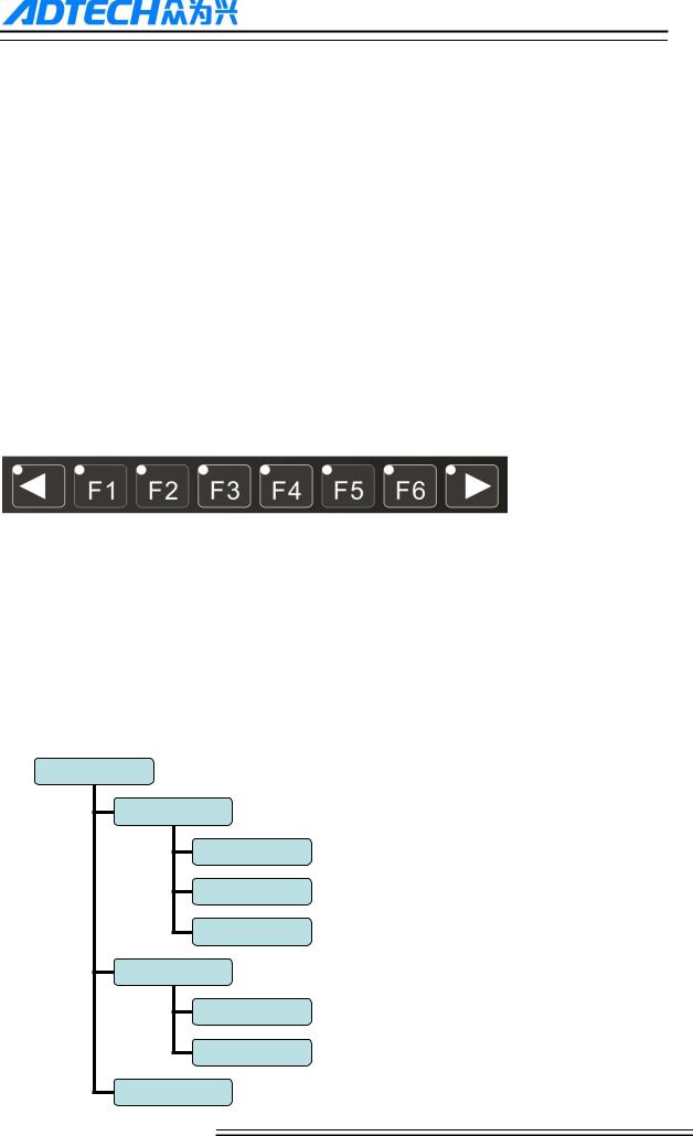
The main menus of the system include [Monitor], [prog], [Para], [Coord] and [Dgnos]. Each main menu contains several submenus, which are shown below:
[Monitor]
[Position]
[Abs]
[Rel]
General
[Path]
Tracking
[Preview]
[MDI]
8
ADTECH 4 series CNC System (maintainance Manual)
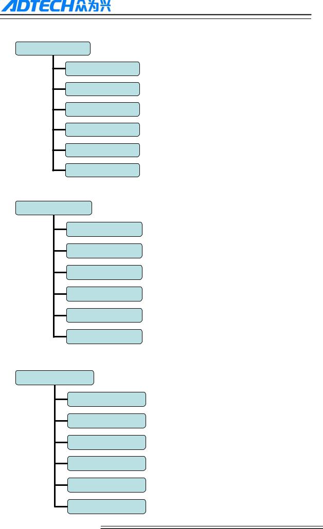
[Prog]
Edit]
[Check]
[CAM ]
[Save as]
[File]
[Del line]
[Para]
[General]
[Axis]
[Manage]
[Tool ]
spindle]
[Port]
Coord
[Coord
[Exp]
[Set]
[HALVE]
[Tcheck]
[Measure]
9
ADTECH 4 series CNC System (maintainance Manual)
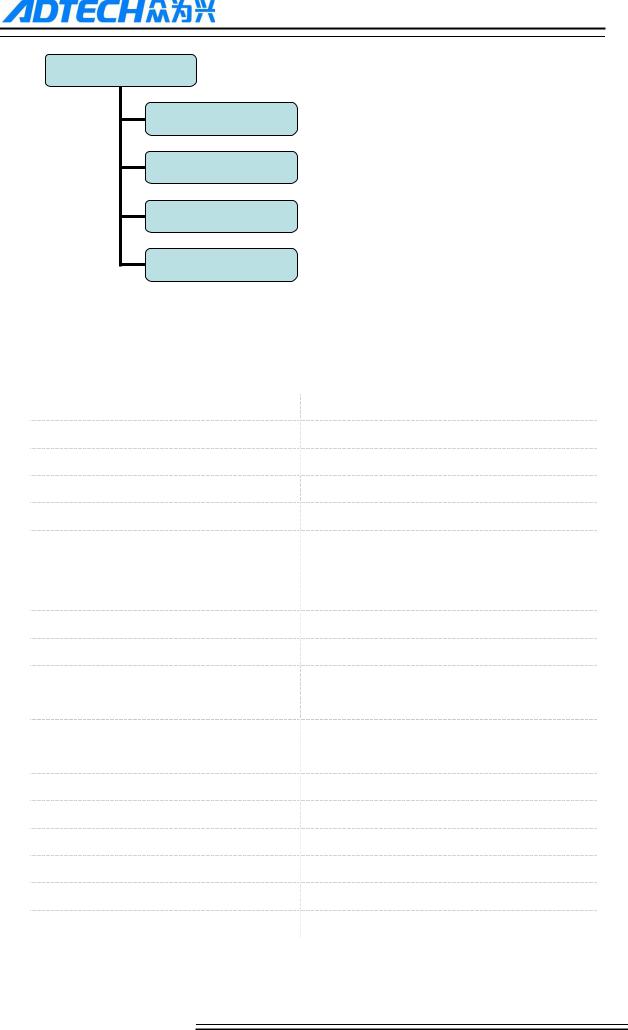
[Dgnos]
[Alert]
[Input]
[Output]
[Module]
3.4 Operating keys
The keys of CNC49XX system are defined below:
Key |
Purpose |
|
|
[RESET] |
Cancel alarm, reset CNC |
Address/number keys |
Enter letters, numbers, etc. |
[EOB], [CAN] |
Confirm or cancel operation |
[EOB], [CAN], [DEL] |
Program edit (insert, delete, modify) |
Mode switch key |
Select operation mode |
Cursor moving key |
Four keys are available: Up/Down: adjust ration, move |
|
cursor between subsections; Left/Right: move cursor to |
|
left/right |
Page key |
Up/Down: Turn pages |
Menu keys |
Select the menus |
Spindle cw rotation |
Press it to rotate spindle cw, and press it again to stop |
|
rotating |
Spindle ccw rotation |
Press it to rotate the spindley ccw, and press it again to |
|
stop rotating |
Coolant |
Coolant on/off |
Lubricant |
Lubricant on/off |
[BDT] |
Block delete on/off |
[SBK] |
Single block function on/off |
[PAUSE] |
Pause automatic running |
[START] |
Start automatic running |
|
|
10

ADTECH 4 series CNC System (maintainance Manual)
4.Manual operation
4.1 Returning to home point manually
CNC machine has special mechanical position, which is called as home point and for tool exchange and coordinates setting. Generally, after power on the tool should be moved to the home point. This operation is also called as go home operation, which will make the CNC system confirm the origin of machine.
The home operation includes program and mechanical mode:
For program home, the action completes when the coordinates of machine are 0, and won‘t check whether home sensors are at position or not;
For mechanical home, the external home sensors are used to locate the origin of the machine ; two checking modes are available:
With the external sensor switch, the go home operation completed when the sensor sensing is successful
The external sensors are used as deceleration switch, the servo home is enabled as home signal after sensed and then stop
You can set the ―Home mode‖ in [Parameter][General], in which 0 (default) indicates program and 1 indicates mechanical. You can also press [SBK] key in home mode to switch among ―Mechanical – Program – Mechanical…‖ quickly. This method doesn‘t conflict with parameter setting.servo home as the home signal, you need to set ―Axis phase Z home enable‖ to ―1‖ in [Parameter][Axis] in mechanical home mode, and the setting will take effect in next home checking.
Several methods are available for tool returning to reference point and the steps as follow:
Each axis returns to home point separately
Press the mode switch key [Home] to select home operation;
Press the composite key [X-], [Y-], [Z-], [A-],[ B-],[C-] at the numbers section to return the corresponding axis to
reference point.
All axis return to reference point simultaneously
Press the mode switch key [Home] to select home operation;
Press the [Start] key ,after Z axis return to home point, then other axis return to hoime point simultaneously. The
automatic home sequence can be configured in the parameters.
Reset machine tool position
11

ADTECH 4 series CNC System (maintainance Manual)
Press the mode switch key [Home] to select home operation;
In [Absolute Position] and [Coordinate System] screen, press [X], [Y], [Z], [A],[ B],[C]respectively to show the value
of corresponding axis position, and then press the [Cancel] key to reset the machine position of current axis, i.e.
current positions are used as machine origin position. After this operation, the system considers it as a home action.
Therefore, when the program is running, the alarm of not home won‘t occur. If you press by mistake, it will switch
the screen and cancel selection automatically.
Reset relative position manually
Press the mode switch key [Manual] to select manual operation;
In [Relative Position] and [Coordinate System] screen, press [X], [Y], [Z], [A] ,[ B],[C] respectively to show the
value of corresponding axis, and then press the [Cancel] key to reset the relative position of current axis.
Note
The tool also can return to home point according to program instruction, i.e. returning tohome point automatically.
Caution:
General ly, the system should do go home operation after power on. If the power off while the machine is working, the
controller also will return to home point when the power on again. So Return to Z axis firstly for preventing tool and workpiece
from colliding and damaging them
.
12

ADTECH 4 series CNC System (maintainance Manual)
4.2 JOG Function
Press the keys on the operation panel or handwheel to move the tool along every axis.
The operation follows:
Press the mode switch key [Manual] to select manual operation;
Press composite keys [X+], [X-]; [Y+], [Y-]; [Z+], [Z-]; [A+], [A-] [B+], [B-]; [C+], [C-] in numbers area to move the tool along selected axis. The keypad follows:
In Jog mode, 5# key can be used to switch the Jog speed and rapid move speed. The rapid move speed of each axis depends on General parameter 009-012 (fastspeed setting). After switching to rapid move speed, the Jog speed of the position interface will be highlighted, while the actual speed of the position interface is sampled from the moving speed of current axis. This value can truly reflect the moving speed of current axis (unit: mm/min);
Note
Only single axis motion is available at Jog mode.
4.3 Single step
Single step mode is similar to Jog mode, the operations are same, but only moves a specified pulse increment every time when press the key.
The operation as follows:
Press the mode switch key [MPG/ step] (this key is composite, and you can press it repeatedly to switch the modes) to select the single step operation;
Press composite keys [X+], [X-]; [Y+], [Y-]; [Z+], [Z-]; [A+], [A-] [B+], [B-]; [C+], [C-]in numbers area to move the tool for a fixed distance via the selected axis. This distance is controlled by four rates (1.000, 0.100, 0.010, 0.001) (unit: mm). To select pulse increment, press Up (+) and Down (-) key in the [Position] interface
4.4MPG
In MPG mode, rotate the handwheel to make the machine perform single step or continuous motion. Determine the feed by testing the handwheel signal of the handheld box. In MPG mode, the feeding axis and feeding unit are determined by the axis selection signal of the handheld box.
The MPG feeding step follows:
Press the mode switch key [MPG/ step] to select MPG operation;
Rotate the switch on the handwheel to select axis (X, Y, Z, A,B,C);
13
ADTECH 4 series CNC System (maintainance Manual)
Rotate the increment switch on the handwheel to select the moving amount (0.1, 0.01, 0.001);
Rotate the handwheel to move the machine. The tool moves certain distance acoording to the handwheel scale setting. (For example, if you select X axis in step and select 0.01 in step , the tool moves 0.01mm every scale). Rotate the handwheel continuously to move each axis continuously.
Note
The MPG mode controls only one axis every time; the faster the handwheel rotates, the faster the machine tool moves.
4.5 Manual auxiliary function operation
Coolant on/off
at MPG/step/Jog mode, press this key to switch on/off the coolant.
Key indicator: No matter in what mode, the key indicator is on if only the coolant is on, or else the indicator is off.
Lubricant on/off
at MPG/step/Jog mode, press this key to switch on/off the lubricant.
Key indicator: No matter in what mode, the key indicator is on if only the lubricant is on, or else the indicator is off.
Spindle CW/stop
In at MPG/step/Jog mode, press this key to rotate the spindle cw and press it again to stop
Key indicator: No matter in what mode, the key indicator is on if only the principal axis is positive rotating, or else the indicator is off.
Spindle CCW/stop
In at MPG/step/Jog mode, press this key to rotate the spindle ccw and press it again to stop
Key indicator: No matter in what mode, the key indicator is on if only the principal axis is reverse rotating, or else the indicator is off.
14

ADTECH 4 series CNC System (maintainance Manual)
General instructions for manual operation keys
Cooling, lubricant, spindle cw/ccw are available in MPG, single step and Jog mode;
When the spindle is rotating, press the reverse rotation key, the Spindle will stop first, then rotate to the reverse direction after pressing it again.
When auxiliary output is on, if the system is switched to other modes, the output is unchanged; you need to press ―Reset‖ key to switch it off, execute the corresponding M code in automatic mode or execute the corresponding M code in MDI interface to turn off the output;
When the spindle work cw/ccw and execute M04/M03 directly, the system first stops cw/ccw rotating and then execute M04/M03 code;
cw/ccw rotating of spindle is stopped while emergency stop pressed, and other outputs can be set according to system parameters.
4.6 Tool setting
Tool setting is the main operation and important skill for CNC machine operater Under certain conditions, tool setting precision can determine the precision of parts, and the tool setting efficiency also affects the CNC processing efficiency directly.there is two ,methods for cnc machine tool setting , i.e. centered and tool setting gauge
4.6.1 Centered
The centered function is that the system calculates the center position of the workpiece automatically while tool setting to realize segment centered, rectangle centered and circle center location.
Note
In the tool setting operation below, if the auxiliary parameters of the coordinate system doesn‘t need setting, the first three
steps can be omitted. Please refer to chapter 9.5 for auxiliary parameters of the coordinate system.
Single axis centered
Select the edit mode;
Select MPG or Jogl mode;
Press [Coord] to enter coordinate system setting interface;
Press the left/right arrow to move the cursor to select coordinate system;
Press [HALVE] to enter centered interface;
15

ADTECH 4 series CNC System (maintainance Manual)
Move the tool to make its side blade touch side A surface of the workpiece, and press [EOB] to record boundary point
1;
Move the tool to make its side blade touch side B surface of the workpiece, and press [EOB] to record boundary point
2;
Press [EOB] to calculate the coordinates of center point;
If all are ok , press [EOB] again to return the result to specified coordinate system.
Square centered
Select the edit mode;
Select MPG or Jogl mode;
Press [Coord] to enter coordinate system setting interface;
Press the left/right arrow to move the cursor to select coordinate system;
Press [HALVE] to enter centered interface;
Move the tool to make its side blade touch side A surface of the workpiece, and press [EOB] to record boundary point
1;
Move the tool to make its side blade touch side B surface of the workpiece, and press [EOB] to record boundary point
2;
Record boundary point 3.4 in the same method;
Press [EOB] after recording all boundary points to calculate the coordinates of center point;
If all are ok, press [EOB] again to return the result to specified coordinate system.
Plane circle (XY plane) centered
Circle centered has two modes, which are three points and two points with specified radius; If the user only types two coordinates in the option of workpiece boundary point and specifies one value for R, the system will determine the circle center with two points and radius automatically; if the user types coordinates of three points in the option of workpiece boundary point, the system will determine the circle center with three points and shield R.
The centered step of three points arc follows:
16
ADTECH 4 series CNC System (maintainance Manual)
Select the edit mode;
Select MPG or Jogl mode;
Press [Coord] to enter coordinate system setting interface;
Press the left/right arrow to move the cursor to select coordinate system;
Press [HALVE] to enter centered interface;
Move the tool to make its side blade touch the surface of round workpiece, and press [EOB] to record boundary point
1;
Move the tool to make its side blade touch another point in the surface of the workpiece, and press [EOB] to record
boundary point 2;
Move the tool to make its side blade touch another point in the surface of the workpiece, and press [EOB] to record
boundary point 3;
Press [EOB] after recording all boundary points to calculate the coordinates of circle center and display in the result
section;
If all are ok , press [EOB] again to return the result to specified coordinate system.
Arc centered checking
under the main menu, press [Monitor], [MDI] to enter the MDI interface, select edit mode, enter program block G55G0X0Y0 (if coordinate system G55 is selected while tool setting), press [Start], [EOB], and the tool moves to workpiece center automatically, indicating that three points arc centered properly.
The validation steps for other tool setting methods are same.
4.6.2 tool setting gauge
tool setting gauge principle:
The tool setting gauge uses external sensor to set the reference point for axis Z, which is similar to home. After changing tool during machine working or changing tool manually, it will automatically check the Z value of current workpiece‘s home.
tool setting gauge usage
17

ADTECH 4 series CNC System (maintainance Manual)
Before using the tool setting gauge, you need to set the parameters. In [Coord] menu, press [set] to show tool setting parameters. After that, press [Tcheck] in the setting interface to execute the tool setting gauge program according to specified parameters.
The action sequence oftool setting gauge follows
Return Z axis to mechanical home first, and then locate spindle to X, Y coordinates of the tool setting gauge;
tool setting gauge start blowing
Z axis moves down, and return when touches tool setting gauge sensor, moves down at lower speed for leaving the
sensor ,records the machine coordinates of Z axis when touches the sensor and import the Z coordinates to current
selected coordinate system;
tool setting gauge stop blowing
Z axis returns to home position.
4.7Data settings
4.7.1 Tool compensation setting
The tool compensation parameters can be set as follow:
Select the edit mode;
In the main menu, press [Coord], and then press submenu [Exp] to enter tool compensation parameter setting
interface;
Move cursor to select the parameter, enter the value and then press [EOB] to modify the parameter where the cursor
locates.
Caution
1:there aree two types for assignment ,direct assignment and incremental assignment. direct assign is that import data
directy to the specified parameter ,the incremental assignment is that the value which is input data plus the current
value will be imported to the parameter
18

ADTECH 4 series CNC System (maintainance Manual)
2:for incremental input and directly input ,there is a symbol at the left side ,‖=‖ is directly input,‖+‖ is incremental
input ,the default setting is directly input(=),in setting dialog,press ↑↓shift directly and incremental input .
4.7.2 System parameter setting
The system parameters can be modified as follow:
Select the edit mode;
In the main menu, press [Para] to enter parameter setting interface;
Then, press the submenu key to select the parameter type (General, manage …);
Move cursor to select the parameter, enter the value and then press [EOB] to modify the parameter where the cursor
locates.
4.8System shoutcut key operation
Under [monitor]mode, [pos] interface,then ―o‖key,the controller will show a dialog ,you can select
one O program (O0001,O0002,and son on ),“EOB” for comfirming.
Under [monitor]mode, [pos] interface,Jog mode,press“←”“→”,for adjusting the spindle speed. Note :this function is effected only when the spindle is working and speed is not 0,so if the speed is 0 ,you can make a program start the spindle and speed is not 0 ,then you can use this shortcut key function.
19

ADTECH 4 series CNC System (maintainance Manual)
5.Automatic operation
The machine works according to cnc program is called as automatic operation. The automatic operation modes of CNC49XX system as follow:
Memory operation, MDI operation, USB disk DNC operation.
5.1 Memory operation
The machine works according to the cnc program in CNC49XX memory, which is called as memory operation.
The program is prestored in the memory. Select and load a program with the operation panel and press the ―Start‖ key to start the automatic operation. Then, press ―Pause‖ key to pause, press ―Start‖ key again to resume the operation, and press ―Reset‖ during operation to stop the program immediately.
The step of memory operation as follows:
Save the program in the memory (read 8.1 for details);
Select [Edit], [File] in the menu or press [File] on the panel to enter file operation interface;
Press the ―arrow‖keys to move the cursor, press [EOB] to select a program and load the file into the work area;
Press [Auto]
Press the [Start] to run the program, and the indicator is on.
5.2MDI operation
In [Monitor] interface, switch to [MDI], enter the program with keypad and machine works according to the program. The program isn‘t saved in system memory, and lost after reboot. This is called as MDI operation and the step as follows:
Press [Edit];
press [Monitor],then press [MDI]
input program manually;
Press [Start], [EOB] to start the program
5.3USB disk(flash drive) DNC
The controller read program from external USB disk and worked without saving in CNC memory. This operation is called as USB disk DNC operation.
The step of USB disk DNC operation as follows:
Insert the USB disk;
20

ADTECH 4 series CNC System (maintainance Manual)
press [File]
Select [data traveler(u)]and press [EOB] to enter;
Move cursor to select a file in the disk;
Press [EOB] to load the file into work area (system buffer);
Press [Auto];
Press the [Start] to run the program, and the indicator is on.
Caution
The system won‘t record the USD disk path. If power off during DNC processing, the program info will be lost after power
on ,so if you want to continue,you should do above steps again.
5.4 Speed rate adjustment
Feeding rate
at auto mode, press ―↑‖, ―↓‖key in [Position] interface to adjust the feeding rate; Press the key once to increase or decrease by 10% (10%-150%).
Jog rate
at Jog mode, press ―↑‖, ―↓‖key in [Position] interface to adjust the Jog rate; Press the key to increase or decrease by 10% (10%-150%).
Spindle speed
at auto or Jog mode, press the ―→‖,―←‖key to adjust the spindle speed by 100r/min. The maximum speed is set by the spindle parameters in the system and the minimum speed is 16r/min. If you press and hold the key for three seconds, the value will be increased or decreased quickly.
5.5 Run idle
(Reserved)
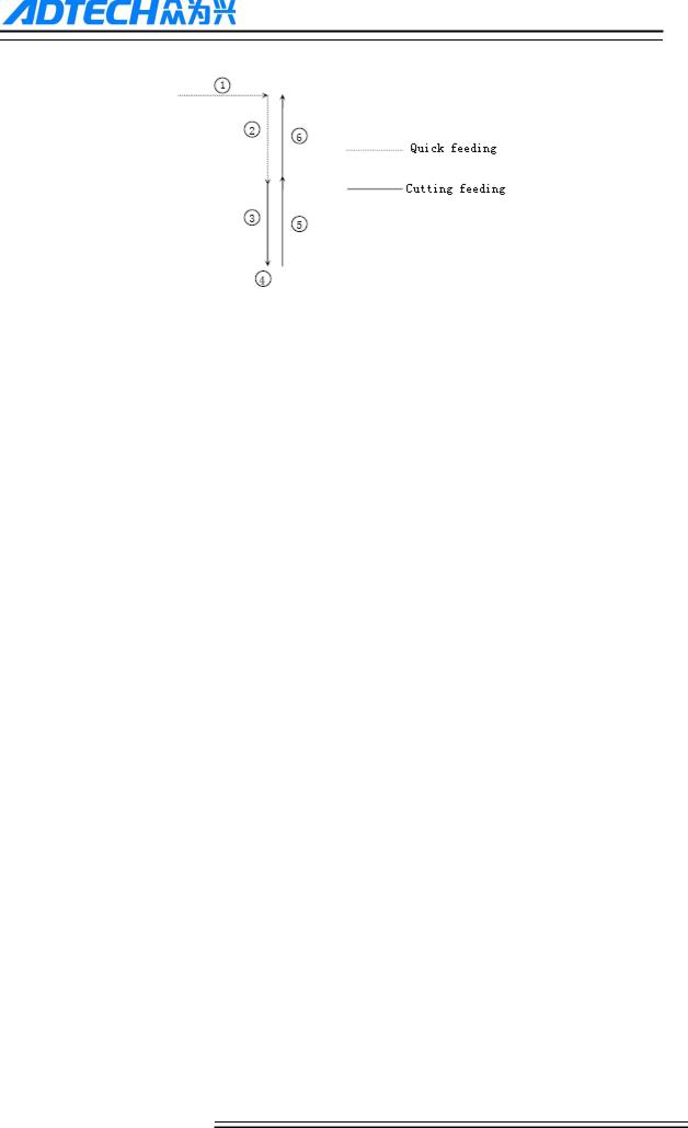
5.6 SBK function
at auto mode, press [SBK] to start the SBK function. Current program stop; press [Start] again and next line stops after executing. The SBK mode can checking the program line by line.
Caution:
In G28-G30, single line also can be stopped at the midpoint;
The stop points of single line in fixed circle are , , in the figure below; when the single line of , stops, the feeding pauses and the pause indicator is on.
21
ADTECH 4 series CNC System (maintainance Manual)
5.7 BDT function
at auto mode, press [BDT] to start the BDT function, which will make the instructions invalid, the instructions are that hace a ‗/‘ symbol at the begaining of program segments.
5.8 Stopping automatic operating
Two methods are available to stop automatic operating,one is that when the controller exctue M01 or M00 code,the other is that press stop key on the panel
Program stops
After executing M00 or M01 code, the controller stop automaticly, which is same as SBK function,after press [start],the controller continue working
After finish a work piece ,the controller stop automaticly
Program ends
After executing M30, the controller stop automaticly, and returns to program start.point
Feeding pause
During automatic operation, press the [Pause] key on the operation panel, the automatic operation pauses and the indicator is on; press [Start] again to continue working and the pause indicator is off
Reset
During automatic operation, press the [Reset] key on the operation panel and the system stops immediately. Here, [Reset] is same as emergency stop button.
22

ADTECH 4 series CNC System (maintainance Manual)
6.Safe operation
6.1 Emergency stop
Press the emergency stop button on the machine which will stop immediately, and all outputs such as spindle and coolant are turned off., but all outputs must be rebooted after emergency stop button release
Caution:
The power supply maybe not cut off when the emergency stop button be pressed. Please refer to the electrical configuration description of the machine manufacturer for details;
Before releasing emergency stop, please eliminate the problems of the machine
6.2 Hard limit over travel
The controller will show alarm when machine touch limit switch. The axis in corresponding direction can‘t move, and only moves in reverse direction. Before the alarm is resetd, the system can‘t enter automatic operation. After investigating the alarm reason, press [Reset] to clear the alarm
6.3 Soft limit over travel
If themachine enters the limt area which set by axis parameters , the controller show alarm , and the machine decelerates and stops. At this moment, you can move the machine to safe direction with Jog mode, and then press [Reset] to release the alarm.
Caution:
During automatic operation, when the machine touches an axis‘s limit switch, the machine decelerates and stops all axis motion, and only displays one alarm
During Jog operation, when the machine touches an axis limit switch, the machine only decelerates and stops motion on current axis, but you can move other axis
When the machine is in safe position, press [Reset] to clear the alarm. Please refer to the manual of the machine for details.
Both hard limit alarm and soft limit alarm have a deceleration stop, and therefore it should have enough sufficient space fore detecting limit switch, or else the limit protection will be disabled due to over travel
23

ADTECH 4 series CNC System (maintainance Manual)
7. Alarm and selfdiagnosis function
The system has several levels, and the alarm numbers also have different type, as follow: 0~1023: G code program running alarm info
1024~2048: System environment alarm info
7.1 NC program execution alarm
0000 |
: |
Reset |
|
|
|
: |
|
|
|
0001 |
Prog No End |
|
||
|
: |
|
|
|
0004 |
M6Tx Abort |
|
||
|
: |
|
|
|
0005 |
Tool Invalid |
|
||
|
: |
|
|
|
0006 |
G Program Repeat Error |
|
||
|
: |
|
|
|
0007 |
G Program Number Error |
|
||
|
: |
|
|
|
0008 |
G7X8X Instruction Run Error |
|
||
|
: |
|
|
|
0009 |
Program Abend |
|
||
|
: |
|
|
|
0010 |
Appointed M01 Instruction Stop |
|
||
|
: |
|
|
|
0011 |
M98 Format Error |
|
||
|
: |
|
|
|
0012 |
Motion Run Error |
|
||
|
: |
|
|
|
0013 |
Current Program No Repair |
|
||
|
: |
|
|
|
0014 |
G Program Format Error |
|
||
|
: |
|
|
|
0015 |
M99 Instruction Abort |
|
||
|
: |
|
|
|
0016 |
Motion Abort |
|
||
|
: |
|
|
|
0017 |
Illegal char |
|
||
|
: |
|
|
|
0018 |
Noneffective Exegesis Character |
|
||
|
: |
|
|
|
0019 |
Illegal G Code |
|
||
|
: |
|
|
|
0020 |
GCode RadialOffset Num Err |
|
||
|
: |
|
|
|
0021 |
Noneffective GCode RadialOffset |
|
||
|
: |
|
|
|
0022 |
Arc Appointed Error |
|
||
|
: |
|
|
|
0023 |
Appointed Noneffective Plane |
|
||
|
: |
|
|
|
0024 |
M98 Instruction Abort |
|
||
|
: |
|
|
|
0025 |
Spindle Appointed Number Error |
|
||
|
: |
|
|
|
0026 |
MCode Instruction Abort |
|
||
|
: |
|
|
|
0027 |
Spi Appointed Err |
|
||
|
: |
|
|
|
0028 |
Motion Repeat Request |
|
||
|
: |
|
|
|
0029 |
Appointed Arc Nonentity |
|
||
|
|
|
|
|
|
|
|
|
|
|
|
|
|
|
24

ADTECH 4 series CNC System (maintainance Manual)
0030 |
: |
Missing X Code Error |
|
: |
|
0031 |
Missing X Code Error |
|
|
: |
|
0032 |
Missing X Code Error |
|
|
: |
|
0033 |
Missing X Code Error |
|
|
: |
|
0034 |
Missing X Code Error |
|
|
: |
|
0035 |
Missing X Code Error |
|
|
: |
|
0036 |
Missing X Code Error |
|
|
: |
|
0037 |
Missing X Code Error |
|
|
: |
|
0038 |
Missing X Code Error |
|
|
: |
|
0039 |
Missing X Code Error |
|
|
: |
|
0040 |
Missing X Code Error |
|
|
: |
|
0041 |
Missing X Code Error |
|
|
: |
|
0042 |
Missing X Code Error |
|
|
: |
|
0043 |
Missing X Code Error |
|
|
: |
|
0044 |
Missing X Code Error |
|
|
: |
|
0045 |
Missing X Code Error |
|
|
: |
|
0046 |
Missing X Code Error |
|
|
: |
|
0047 |
Missing X Code Error |
|
|
: |
|
0048 |
Screw Value Repeat Error |
|
|
: |
|
0049 |
System Abort |
|
|
: |
|
0050 |
Factitious return |
|
|
: |
|
0051 |
no parameter input |
|
|
: |
|
0052 |
no store address for Gcode pro num form |
|
|
|
|
7.2 System environment alarm
1024 |
: |
no \"return zero\ |
|
|
|
|
|
|
|
1. The system doesn‘t perform home action after started |
|
|
|
|
|
1025 |
: |
4 |
- direction program limit |
|
|
|
|
1026 |
: |
4 |
+ direction program limit |
|
|
|
|
1027 |
: |
Z - direction program limit |
|
|
|
|
|
1028 |
: |
Z + direction program limit |
|
|
|
|
|
1029 |
: |
Y - direction program limit |
|
|
|
|
|
1030 |
: |
Y + direction program limit |
|
|
|
|
|
1031 |
: |
X - direction program limit |
|
|
|
|
|
25

ADTECH 4 series CNC System (maintainance Manual)
1032 |
: |
X+ direction program limit |
|
|
|
|
|
|
|
1033 |
: |
4 - direction machine limit |
|
|
|
|
|
|
|
1034 |
: |
4 + direction machine limit |
|
|
|
|
|
|
|
1035 |
: |
Z - direction machine limit |
|
|
|
|
|
|
|
1036 |
: |
Z + direction machine limit |
|
|
|
|
|
|
|
1037 |
: |
Y - direction machine limit |
|
|
|
|
|
|
|
1038 |
: |
Y + direction machine limit |
|
|
|
|
|
|
|
1039 |
: |
X - direction machine limit |
|
|
|
|
|
|
|
1040 |
: |
X+ direction machine limit |
|
|
|
|
|
|
|
|
|
When controller shows limit alarm. Please check corresponding limit sensor point or parameters. |
||
|
|
If hard limit occurs, and the appearance of the sensor point doesn‘t has any problem, enter the diagnosis |
||
|
|
mode and check the state of the input port. If the state is valid, please eliminate in sequence. Disconnect |
||
|
|
the input IO cable and check whether the sense disappears. If yes, please check the circuit. If the |
||
|
|
problem still exists, the internal optocoupler is broken. Please contact the supplier. |
||
|
|
|
|
|
1041 |
: |
Emergency stop |
|
|
|
|
|
|
|
|
|
Check Emergency stop button of the handheld box is pushed down or not |
||
|
|
External emergency stop 2 input is push down?;check whether IO assignment has conflict or |
||
|
|
interference. |
||
|
|
Search for corresponding function ports in IO configuration, and then check in input diagnosis. |
||
|
|
|
|
|
1042 |
: |
X Sevor driver alarm |
|
|
|
|
|
|
|
1043 |
: |
Y Sevor driver alarm |
|
|
|
|
|
|
|
1044 |
: |
Z Sevor driver alarm |
|
|
|
|
|
|
|
1045 |
: |
4 Sevor driver alarm |
|
|
|
|
|
|
|
|
|
Servo alarm; if there is no alarm on servo , parameter P2(axis parameter).001~004 setting and actual |
||
|
|
servo alarm level may be reverse. Please modify the parameters. |
||
|
|
The corresponding function ports are IN34~37, which can be checked in input diagnosis. |
||
|
|
|
|
|
1046 |
: |
Axis's physical line redefine |
|
|
|
|
|
|
|
|
|
axis No. setting by parameter P2.45~P2.49 is specified repeatedly |
||
|
|
|
||
1047 |
: |
spi no to home |
|
|
|
|
|
|
|
|
|
|
||
1048 |
: |
workpiece no lock |
|
|
|
|
|
|
|
|
|
|
||
1049 |
: |
safe signal can't detect |
|
|
|
|
|
|
|
|
|
|
||
1051 |
: |
air no enough |
|
|
|
|
|
|
|
|
|
|
|
|
|
|
|
|
|
|
|
26 |
|
|
 Loading...