


ADT-CNC4640
CNC46XX Series CNC System
Maintenance Manual
Adtech (Shenzhen) CNC Technology Co., Ltd. Add: 5/F, Bldg/27-29, Tianxia IC Industrial Park, Yiyuan Rd, Nanshan District, Shenzhen Postal code: 518052
Tel: 0755-26722719 |
Fax: 0755-26722718 |
E-mail: adtcnc@machine-controller.com |
http://www.machine-controller.com |
|
|
|
|

Copyright
Adtech (Shenzhen) Technology Co., Ltd. (Adtech hereafter) is in possession of the copyright of this manual. Without the permission of Adtech, the imitation, copy, transcription and translation by any organization or individual are prohibited. This manual doesn’t contain any assurance, stance or implication in any form. Adtech and the employees are not responsible for any direct or indirect data disclosure, profits loss or cause termination caused by this manual or any information about mentioned products in this manual. In addition, the products and data in this manual are subject to changes without prior notice.
All rights reserved.
Adtech (Shenzhen) CNC Technology Co., Ltd.
1-- 2 -

Version History
Item No. |
|
First uploaded on |
|
Version No. |
Pages |
Compiled by |
Typeset by |
||
|
|
|
|
|
|
|
|
|
|
XT20100819 |
|
2011-3-01 |
|
A0101 |
119 |
Yang Jipeng |
Yang Jipeng |
||
|
|
|
|
|
|
|
|
|
|
XT20100819 |
|
2011-9-22 |
|
A0201 |
102 |
Yang Jipeng |
Yang Jipeng |
||
|
|
|
|
|
|
|
|
|
|
|
|
|
|
|
|
Revision |
|
|
|
|
|
|
|
|
|
|
|
||
Date |
Version/Page |
|
Result |
|
|
Confirmed by |
|
||
|
|
|
|
|
|
|
|
|
|
|
|
|
|
|
|
|
|
|
|
|
|
|
|
|
|
|
|
|
|
|
|
|
|
|
|
|
|
|
|
|
|
|
|
|
|
|
|
|
|
|
|
|
|
|
|
|
|
|
|
|
|
|
|
|
|
|
|
|
|
|
|
|
|
|
|
|
|
|
|
|
|
|
|
|
|
|
|
|
|
|
|
|
|
|
|
|
|
|
|
|
|
|
|
|
|
|
|
|
|
|
|
|
|
|
|
|
|
|
|
Remark:
We have collated and checked this Manual strictly, but we can’t ensure that there are no error and omission in this Manual.
Due to constant improvement of product functions and service quality, any products and software described in this manual and the content of the manual are subject to changes without prior notice.
1-- 3 -

Adtech CNC Technology Co., Ltd. Contents
Contents |
|
||
1. |
Foreword ............................................................................................................................ |
- 3 - |
|
2. |
System technical characteristics ...................................................................................... |
- 3 - |
|
|
2.1 |
System structure ................................................................................................................................. |
- 3 - |
|
2.2 |
System technical parameters .............................................................................................................. |
- 3 - |
|
2.3 |
System function.................................................................................................................................. |
- 5 - |
|
|
2.3.1 Self-diagnosis.................................................................................................................................................... |
- 5 - |
|
|
2.3.2 Compensation ................................................................................................................................................... |
- 5 - |
|
|
2.3.3 Abundant instruction system............................................................................................................................. |
- 5 - |
|
|
2.3.4 Full Chinese menu operation & full screen edit................................................................................................ |
- 5 - |
|
|
2.3.5 Abundant error-correction functions ................................................................................................................. |
- 5 - |
|
|
2.3.6 Program exchange between CNC system and PC............................................................................................. |
- 5 - |
|
2.4 |
System operating condition................................................................................................................ |
- 5 - |
3. |
Operating panel ................................................................................................................. |
- 6 - |
|
|
3.1 |
LCD/keypad ....................................................................................................................................... |
- 6 - |
|
3.2 |
LCD brightness adjustment................................................................................................................ |
- 7 - |
|
3.3 |
System menus..................................................................................................................................... |
- 8 - |
|
3.4 |
Operating keys.................................................................................................................................. |
- 11 - |
4. |
Manual operation ............................................................................................................ |
- 12 - |
|
|
4.1 |
Returning to reference point manually............................................................................................. |
- 12 - |
|
4.2 |
Continuous feeding manually........................................................................................................... |
- 13 - |
|
4.3 |
Single step feeding ........................................................................................................................... |
- 13 - |
|
4.4 |
Handwheel feeding........................................................................................................................... |
- 13 - |
|
4.5 |
Manual auxiliary function operation ................................................................................................ |
- 14 - |
|
4.6 Tool setting....................................................................................................................................... |
- 15 - |
|
|
|
4.6.1 Centered (M series)......................................................................................................................................... |
- 15 - |
|
|
4.6.2 Tool regulator (M series)................................................................................................................................. |
- 16 - |
|
|
4.6.3 Tool setting by test cutting (L series) .............................................................................................................. |
- 17 - |
|
4.7 |
Data settings..................................................................................................................................... |
- 17 - |
|
|
4.7.1 Tool compensation data setting....................................................................................................................... |
- 17 - |
|
|
4.7.2 System parameter setting ................................................................................................................................ |
- 17 - |
5. |
Automatic operation ....................................................................................................... |
- 18 - |
|
|
5.1 |
Memory operation............................................................................................................................ |
- 18 - |
|
5.2 |
MDI operation.................................................................................................................................. |
- 18 - |
|
5.3 USB disk DNC................................................................................................................................. |
- 18 - |
|
|
5.4 |
Speed rate adjustment....................................................................................................................... |
- 18 - |
|
5.5 |
Run idle ............................................................................................................................................ |
- 19 - |
|
5.6 |
SBK function.................................................................................................................................... |
- 19 - |
|
5.7 |
BDT function.................................................................................................................................... |
- 19 - |
|
5.8 |
Stopping automatic operating........................................................................................................... |
- 19 - |
6. |
Safe operation .................................................................................................................. |
- 20 - |
|
|
6.1 |
Emergency stop................................................................................................................................ |
- 20 - |
|
6.2 |
Hard limit over travel ....................................................................................................................... |
- 20 - |
|
6.3 |
Soft limit over travel ........................................................................................................................ |
- 20 - |
7. Alarm and selfdiagnosis function ................................................................................ |
- 21 - |
||
|
7.1 |
NC program execution alarm ........................................................................................................... |
- 21 - |
|
7.2 |
System environment alarm............................................................................................................... |
- 22 - |
|
7.3 Alarm processing.............................................................................................................................. |
- 23 - |
|
|
7.4 |
Self-diagnosis function..................................................................................................................... |
- 24 - |
8. Program saving & editing............................................................................................... |
- 25 - |
||
|
8.1 |
Saving the program in the memory .................................................................................................. |
- 25 - |
|
|
8.1.1 Keypad input (new program) .......................................................................................................................... |
- 25 - |
|
|
8.1.2 PC serial port input ......................................................................................................................................... |
- 25 - |
|
|
8.1.3 Copying processing files from USB disk........................................................................................................ |
- 25 - |
|
8.2 |
Reading programs into work area .................................................................................................... |
- 25 - |
|
|
8.2.1 Reading programs from controller into work area .......................................................................................... |
- 25 - |
|
|
8.2.2 Reading programs from USB disk into work area .......................................................................................... |
- 25 - |
|
8.3 |
Editing & modifying programs ........................................................................................................ |
- 25 - |
|
8.4 |
Deleting files .................................................................................................................................... |
- 26 - |
|
|
8.4.1 Deleting files in memory................................................................................................................................. |
- 26 - |
9. |
Main interfaces of the system ......................................................................................... |
- 27 - |
|
|
|
|
|
|
|
|
|
I

ADT-CNC46XX
|
9.1 Position interface ............................................................................................................................. |
- 27 - |
|
9.2 Edit interface.................................................................................................................................... |
- 29 - |
|
9.3 MDI interface .................................................................................................................................. |
- 30 - |
|
9.4 File management.............................................................................................................................. |
- 31 - |
|
9.5 Graphic simulation........................................................................................................................... |
- 31 - |
|
9.6 Parameter interface.......................................................................................................................... |
- 32 - |
|
9.7 Compensation interface ................................................................................................................... |
- 35 - |
|
9.8 M series workpiece coordinate system setting interface.................................................................. |
- 36 - |
|
9.9 Controller diagnosis interface (diagnosis) ....................................................................................... |
- 39 - |
|
9.10 Macro variable view interface (macro variable)............................................................................ |
- 39 - |
|
9.11 Current mode instruction info........................................................................................................ |
- 40 - |
10. |
System maintenance........................................................................................................ |
- 41 - |
|
10.1 Restart............................................................................................................................................ |
- 41 - |
|
10.2 System upgrade.............................................................................................................................. |
- 41 - |
|
10.3 Reset .............................................................................................................................................. |
- 41 - |
|
10.4 Parameter backup and restore........................................................................................................ |
- 41 - |
|
10.5 Entering BIOS ............................................................................................................................... |
- 41 - |
11. |
System parameters.......................................................................................................... |
- 42 - |
|
11.1 Parameter index list ....................................................................................................................... |
- 42 - |
|
11.2 Comprehensive parameters (P1.)................................................................................................... |
- 52 - |
|
11.3 Axis parameter configuration (P2.)................................................................................................ |
- 62 - |
|
11.4 Management parameters (P3.) ....................................................................................................... |
- 69 - |
|
11.5 Tool magazine parameters (P4.)..................................................................................................... |
- 72 - |
|
11.6 Principal axis parameters (P5.) ...................................................................................................... |
- 73 - |
|
11.7 Port configuration (P6.) ................................................................................................................. |
- 74 - |
12. |
Hardware interface definition and connection instructions ....................................... |
- 76 - |
|
12.1 Installation layout .......................................................................................................................... |
- 76 - |
|
12.1.1 External interface diagram ............................................................................................................................ |
- 76 - |
|
12.1.2 Mounting dimensions.................................................................................................................................... |
- 77 - |
|
12.1.3 Installation precautions ................................................................................................................................. |
- 78 - |
|
12.2 Interface definition......................................................................................................................... |
- 80 - |
|
12.2.1 Motor drive control interface (XS1..XS4)..................................................................................................... |
- 80 - |
|
12.2.2 Digital input interface (XS5)......................................................................................................................... |
- 83 - |
|
12.2.3 Digital output interface (XS6)....................................................................................................................... |
- 86 - |
|
12.2.4 Handheld box interface (XS7)....................................................................................................................... |
- 89 - |
|
12.2.5 Analog output interface (XS8) ...................................................................................................................... |
- 90 - |
|
12.2.6 Principal axis encoder interface (XS12)........................................................................................................ |
- 91 - |
|
12.2.7 RS232 transmission interface (XS9) ............................................................................................................. |
- 93 - |
|
12.2.8 USB memory connection interface (XS10)................................................................................................... |
- 93 - |
|
12.2.9 PC USB communication interface (XS11) .................................................................................................... |
- 93 - |
|
12.3 Electrical connection diagram ....................................................................................................... |
- 94 - |
|
12.3.1 Symbol schematic diagram ........................................................................................................................... |
- 94 - |
|
12.3.2 Power connection diagram............................................................................................................................ |
- 95 - |
|
12.3.3 Servo drive connection diagram.................................................................................................................... |
- 96 - |
|
12.3.4 Step connection diagram ............................................................................................................................... |
- 97 - |
|
12.3.5 IO electrical connection diagram................................................................................................................... |
- 98 - |
II
Adtech CNC Technology Co., Ltd. |
1. Program saving & editing |
|
|
|
|
1. Foreword
CNC4640/4620 numerical control system is economic embedded system developed by Adtech (Shenzhen) CNC Technology Co., Ltd. for milling machines and machining centers, where CNC4640 is four axes motion controller and CNC4620 is two axes motion controller.
Instructions and reading convention of the Manual
Before using this CNC system, please read this Manual carefully to operate properly. Terminology note and reading convention in this Manual:
CNC4640 and CNC4620 are control systems with different axes and same hardware functions. The programs developed on this platform contain M series software for milling machines and L series software for lathes. Different software has different functions and masks.
M series are system for milling machine motion. The ‘M’ or “M series” mark indicates specific interface or function for milling machine software system.
L series are system for lathe motion. The ‘L’ or “L series” mark indicates specific interface or function for lathe software system.
“CNC system”, “NC controller” and “CNC46XX” mentioned in this Manual all refer to CNC4640/4620;
The articles marked with “Caution” prompt users to pay special attention for operation or setting, or else this operation may fail or certain action can’t be performed.
2. System technical characteristics
2.1System structure
ÜCPU: ARM industrial mainboard;
ÜCommunication: USB interface;
ÜCapacity: 64MB RAM, 60M Flash ROM;
ÜFeedback: AB phase pulse feedback;
ÜControl: FPGA motion controller;
ÜHand pulse: Incremental hand encoder;
ÜDisplay: 800×480 pixels 7” LCD;
ÜI/O full optical coupling isolation;
ÜTouch/film type operation panel;
ÜHighly anti-interference switching power supply;
ÜRS232 interface
2.2System technical parameters
|
|
|
|
|
|
Function |
Name |
Specification |
|
|
|
|
|
|
|
|
Control axes |
4 axes (CNC4640 series) |
|
|
|
2 axes (CNC4620 series) |
|
|
|
|
|
|
|
|
|
|
|
|
|
Control axis |
|
4 axes linear interpolation (CNC4640 |
|
|
|
series) |
|
|
|
|
|
|
|
|
|
Simultaneous control axes |
2 axes linear interpolation (CNC4620 |
|
|
|
|
series) |
|
|
|
|
2 axes arc interpolation |
|
|
|
|
|
|
|
|
|
|
|
|
|
Minimum setting unit |
0.001mm |
|
|
Input instruction |
|
|
|
|
|
|
|
|
|
Minimum moving unit |
0.001mm |
|
|
|
|
|
|
|
|
|
|
|
|
|
|
Maximum instruction value |
±9999.999mm |
|
|
|
|
|
|
|
|
|
|
|
|
|
|
|
|
- 3 -

Adtech CNC Technology Co., Ltd. |
|
|
|
|
2. Program saving & editing |
|||||
|
|
|
|
|
|
|
|
|
|
|
|
|
|
|
|
|
|
|
|
|
|
|
|
|
|
|
|
|
|
|
|
|
|
Function |
|
|
Name |
|
Specification |
|
|
||
|
|
|
|
|
|
|
|
|
|
|
|
|
|
Fast feeding speed |
|
|
X axis, Y axis, Z axis, A axis: 9999 |
|
|
||
|
|
|
|
|
mm/min (maximum) |
|
|
|||
|
|
|
|
|
|
|
|
|
|
|
|
|
|
|
|
|
|
|
|
|
|
|
|
|
Feeding speed range |
|
Per minute |
|
1~9999mm/min |
|
|
|
|
Feeding |
|
|
|
|
|
|
|
||
|
|
|
Per rotation |
|
1~500rpm |
|
|
|||
|
|
|
|
|
|
|
|
|
||
|
|
|
|
|
|
|
||||
|
|
|
Automatic acceleration/deceleration |
|
Yes |
|
|
|||
|
|
|
|
|
|
|
|
|
||
|
|
|
Feeding speed rate |
|
|
10~150% |
|
|
||
|
|
|
|
|
|
|
|
|
|
|
|
|
|
Continuously manual feeding, |
|
Yes |
|
|
|||
|
|
|
|
|
|
|
||||
|
|
|
|
|
|
|
|
|
|
|
|
|
|
|
|
|
|
|
|
|
|
|
Manual |
|
|
|
|
|
|
All control axes return to reference point |
|
|
|
|
Returning to reference point manually |
|
simultaneously |
|
|
||||
|
|
|
|
|
|
|||||
|
|
|
|
|
|
|
|
(allow setting order of priority) |
|
|
|
|
|
|
|
|
|
|
|||
|
|
|
|
|
|
|
||||
|
|
|
Single step/handwheel function |
|
Yes |
|
|
|||
|
|
|
|
|
|
|
|
|
||
|
Interpolation |
|
Positioning, |
linear |
interpolation, |
arc |
G00, G01, G02/G03 |
|
|
|
|
|
interpolation |
|
|
|
|
|
|
|
|
|
|
|
|
|
|
|
|
|
|
|
|
|
|
|
|
|
|
|
|||
|
|
|
|
|
|
|
||||
|
Operating mode |
|
MDI, auto, manual, single step, edit |
|
Yes |
|
|
|||
|
Testing function |
|
Test run, single program section, Handwheel |
Yes |
|
|
||||
|
|
|
|
|
|
|
|
|
|
|
|
|
|
Pause (sec/ms) |
|
|
|
|
G04 X/P_ |
|
|
|
Coordinate system |
and |
|
|
|
|
|
|
|
|
|
Coordinate system setting |
|
G92 (M series) |
|
|
|||||
|
pause |
|
|
G50 (L series) |
|
|
||||
|
|
|
|
|
|
|
|
|
||
|
|
|
|
|
|
|
||||
|
|
|
Automatic coordinate system setting |
|
Yes |
|
|
|||
|
|
|
|
|
|
|
|
|||
|
Safe functions |
|
Soft & hard limit check |
|
|
Yes |
|
|
||
|
|
|
|
|
|
|
|
|
|
|
|
|
|
|
|
|
|
|
|
|
|
|
|
|
Emergency stop |
|
|
|
|
Yes |
|
|
|
|
|
|
|
|
|
|
|
|
|
|
|
|
|
|
|
|
|
|
|
|
|
|
|
|
|
|
|
|
Capacity: 60MB |
|
|
|
|
|
|
|
|
|
|
100 work areas |
|
|
|
Program storage |
|
Program storage capacity, storage quantity |
|
No limit on processing file quantity |
|
|
|||
|
|
|
|
|
|
|
|
|
|
|
|
|
|
|
|
|
|
|
|
|
|
|
|
|
|
|
|
|
|
Insert, modify, delete, cancel |
|
|
|
|
|
Program edit |
|
|
|
|
|
|
|
|
Program edit |
|
|
|
|
|
|
|||
|
|
|
|
|
||||||
|
|
Program No., |
sequence No., address, |
Yes |
|
|
||||
|
|
|
character retrieval |
|
|
|
|
|
||
|
|
|
|
|
|
|
|
|
|
|
|
|
|
|
|
|
|
|
|
|
|
|
|
|
Decimal point programming |
|
Yes |
|
|
|||
|
|
|
|
|
|
|
||||
|
|
|
|
|
|
|
|
|||
|
|
|
|
|
|
|
|
|||
|
|
|
800×480 pixels 7” LCD |
|
|
|
|
|||
|
Display |
|
|
|
|
|
|
|||
|
|
|
|
|
|
|||||
|
|
Position screen, program edit |
|
Yes |
|
|
||||
|
|
|
Tool compensation setting, alarm display |
|
|
|
|
|||
|
|
|
Handwheel test, diagnosis screen |
|
|
|
|
|||
|
|
|
Parameter setting, graphic simulation |
|
|
|
|
|||
|
|
|
|
|
|
|
|
|
|
|
|
|
|
Auxiliary function |
|
|
M code |
|
|
||
|
|
|
|
|
|
|
|
|||
|
|
|
|
|
|
|
|
|
|
|
|
|
|
|
|
|
|
|
|
|
|
|
M, S, T function |
|
|
|
|
|
|
S0-S15 (gear position control) |
|
|
|
|
Principal axis function |
|
|
S15-S99999 (analog) |
|
|
|||
|
|
|
|
|
|
|
||||
|
|
|
|
|
|
|
|
|
|
|
|
|
|
|
|
|
|
|
|
|
|
|
|
|
Tool function |
|
|
|
|
T code |
|
|
|
|
|
|
|
|
|
|
|
|
|
|
|
|
|
|
|
|
|
30 tools length, radius compensation |
|
|
|
|
|
Tool compensation memory |
|
|
|
|
|||
|
Compensation function |
|
|
|
|
|
|
|
|
|
|
|
|
|
|
|
|
|
|
|
|
|
|
|
Reverse clearance compensation |
|
Yes |
|
|
|||
|
|
|
|
|
|
|
||||
|
|
|
|
|
|
|
|
|
||
|
|
|
|
|
|
|
|
|
||
|
|
|
Measurement centered |
|
|
Yes |
|
|
||
|
|
|
Automatic tool regulator |
|
|
|
||||
|
|
|
|
|
|
|
||||
|
Other functions |
|
|
|
|
|
|
|
|
|
|
|
|
|
|
|
|
|
|
|
|
|
|
Specify arc radius R/center position |
|
Yes |
|
|
||||
|
|
|
|
|
|
|||||
|
|
|
|
|
|
|
|
|
||
|
|
|
|
|
|
|
|
|||
|
|
|
Electronic gear ratio |
|
|
Yes |
|
|
||
|
|
|
|
|
|
|
|
|
|
|
|
|
|
|
|
|
|
|
|
|
|
- 4 -

Adtech CNC Technology Co., Ltd. |
2. Program saving & editing |
|
|
|
|
2.3 System function
2.3.1 Self-diagnosis
Diagnose CPU, memory, LCD, I/O interface, parameter state, coordinates and processing program comprehensively every time the system is started or reset; diagnose power supply, principal axis, limit and I/O ports in real-time during operating.
2.3.2 Compensation
Automatic reverse clearance compensation
Automatic tool length compensation
Automatic tool radius compensation
Automatic tool radius biasing and automatic tool tip transition
2.3.3 Abundant instruction system
Scaling instruction
Mirror processing instruction Tool biasing instructions
Program cycle, program skip, program shift, program transfer, different end processing modes, macro definition and program management instructions
Fixed-point instructions: starting point, setting point, etc. Linear, arc and spiral interpolation instructions
Six workpiece coordinate systems, nine extension coordinate systems and one reference point
2.3.4 Full Chinese menu operation & full screen edit
4640/4620 CNC system uses cascading menu structure and full Chinese operation to ensure simple operation and visibility.
2.3.5 Abundant error-correction functions
Point out the nature and correct the errors in operation.
2.3.6 Program exchange between CNC system and PC
Perform CAD/CAM/CAPP auxiliary programming with abundant software in PC, and then transmit CNC program to the system through communication interface (USB disk, RS232 interface), or transmit the programs from the system to PC.
2.4 System operating condition
Operating voltage |
24V DC (with filter) |
|
Operating temperature |
0 — 45 |
|
Optimum operating temperature |
5 — 40 |
|
Operating humidity |
10%——90% (no condensing) |
|
Optimum operating humidity |
20%——85% |
|
Storage temperature |
0 —50 |
|
Storage humidity |
10%——90% |
|
Operating environment |
No excessive dust, acid, alkali, corrosive and explosive gases, no strong |
|
electromagnetic interference |
||
|
- 5 -

Adtech CNC Technology Co., Ltd. |
3. Program saving & editing |
|
|
|
|
3. Operating panel
3.1 LCD/keypad
Keypad
Fig. 3.1 CNC4640 Operating Panel Diagram
Note:
Press the submenu buttons to perform the operations of submenus.
Manual axis moving and edit & input are composite. It has different definitions according to the modes. System working mode switch section is used to switch working modes, which can improve the security
and system performance. Handwheel and single step mode are switched with Repeat button.
- 6 -
Adtech CNC Technology Co., Ltd. |
3. Operating panel |
|
|
|
|
LCD unit
Fig. 3.2 CNC4640 LCD Screen Diagram
Note:
Screen info shows the information of current window Working mode info shows currently selected working mode System main screen shows current main screen.
The submenu options are used to switch submenus with left triangle, F1~F6 and right triangle. The right arrow is used to turn pages, and the left arrow is used to close the submenus in next level and previous menu.
3.2 LCD brightness adjustment
CNC46XX doesn’t support brightness adjustment.
- 7 -
Adtech CNC Technology Co., Ltd. |
3. Program saving & editing |
|
|
|
|
3.3 System menus
CNC46XX system uses cascading menu structure. You can press the following keys to operate the menus.
Press a key to show the corresponding content in the bottom of the LCD. Key in the left: Return to previous menu
Key in the right: Turn pages to show other menus of same level
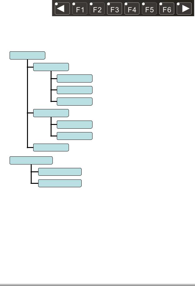
The main menus of the system include [Monitor], [Edit], [Parameter], [Coordinate] and [Diagnosis]. Each main menu contains several submenus, which are shown below:
[Monitor]
[Position]
[Absolute Position]
[Relative Position]
[Comprehensive
[Track]
[Preview]
[Select Plane]
[MDI]
[Edit]
[Program Edit]
[File]
- 8 -
Adtech CNC Technology Co., Ltd. |
3. Operating panel |
|
|
|
|
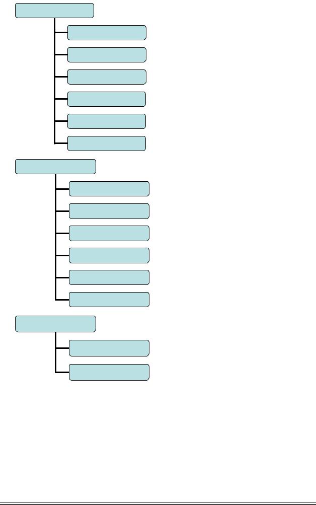
[Parameter]
[Comprehensive
Parameter]
[Axis Configuration]
[Management]
[Tool Magazine]
[Principal Axis]
[Port]
M Series [Coordinates]
[Coordinate Setting]
[Compensation]
[Coordinate Parameter]
[Centered Measurement]
[Tool Regulator]
[Measurement]
L Series [Coordinates]
[Compensation]
[Tool Setting for Test
Cutting]
- 9 -

Adtech CNC Technology Co., Ltd. |
3. Program saving & editing |
|
|
|
|
[Diagnosis]
[Alarm Info]
[Input Diagnosis]
[Output Diagnosis]
[DA Diagnosis]
- 10 -

Adtech CNC Technology Co., Ltd. |
3. Operating panel |
|
|
|
|
3.4 Operating keys
The keys of CNC46XX system are defined below:
Key |
Purpose |
[RESET] |
Cancel alarm, reset CNC |
Address/number keys |
Enter letters, numbers, etc. |
[EOB], [CAN] |
Confirm or cancel operation |
[EOB], [CAN], [DEL] |
Program edit (insert, delete, modify) |
Mode switch key |
Select operating mode |
Cursor moving key |
Four keys are available: Up/Down: adjust ration, move |
|
cursor between subsections; Left/Right: move cursor to |
|
left/right |
Page key |
Up/Down: Turn pages |
Menu keys |
Select the menus |
Principal axis positive rotation |
Press it to rotate the principal axis positively, and press it |
|
again to stop rotating |
Principal axis reverse rotation |
Press it to rotate the principal axis reversely, and press it |
|
again to stop rotating |
Coolant |
Coolant on/off |
Lubricant |
Lubricant on/off |
[BDT] |
Block delete on/off |
[SBK] |
Single block function on/off |
[PAUSE] |
Pause automatic running |
[START] |
Start automatic running |
- 11 -

Adtech CNC Technology Co., Ltd. |
4. Manual operation |
|
|
|
|
4. Manual operation
4.1 Returning to reference point manually
CNC machine tool has specific mechanical position, which is called as reference point and for tool exchange and coordinates setting. Generally, when the power supply is connected, the tool should be moved to the reference point. This operation is also called as home operation, which will make the CNC system confirm the origin of machine tool.
The home operation includes program and mechanical mode:
For program home, the action completes when the coordinates of machine tool are 0, and won’t check whether origin switch is in position;
For mechanical home, the external home sensor switch is used to locate the origin of the machine tool; two checking modes are available:
With the external sensor switch, the home operation completes when the sensing is successfully repeatedly.
The external sensor switch is used as deceleration switch, the servo home is enabled as home signal after sensing and then the sensing stops.
You can set the “Home mode” in [Parameter][Comprehensive Parameter], in which 0 (default) indicates program and 1 indicates mechanical. You can also press [SBK] key in home mode to switch among “Mechanical – Program – Mechanical…” quickly. This method doesn’t conflict with parameter setting. You can select accordingly. To use servo home as the home signal, you need to set “Axis phase Z home enable” to “1” in [Parameter][Axis Configuration] in mechanical home mode, and the setting will take effect in next home checking.
Several methods are available for tool returning to reference point and the steps follow:
Each axis returns to reference point separately
ÜPress the mode switch key [Home] to select home operation;
ÜPress the composite key [X-], [Y-], [Z-], [A-] in the numbers section to return the corresponding axis to reference point.
The axes return to reference point simultaneously
ÜPress the mode switch key [Home] to select home operation;
ÜPress the [Start] key to return Z axis to reference point, and other axes return to reference point simultaneously. The automatic home sequence can be configured in the parameters.
Reset machine tool position
ÜPress the mode switch key [Home] to select home operation;
ÜIn [Absolute Position] and [Coordinate System] screen, press [X], [Y], [Z], [A] respectively to show the value of corresponding axis position, and then press the [Cancel] key to reset the machine tool position of current axis, i.e. current point is used as machine tool origin. After this operation, the system considers it as a home action. Therefore, when the program is running, the alarm of not home won’t occur. If you press by mistake, it will switch the screen and cancel selection automatically.
Reset relative position manually
Ü Press the mode switch key [Manual] to select manual operation;
Ü In [Relative Position] and [Coordinate System] screen, press [X], [Y], [Z], [A] respectively to show the value of corresponding axis, and then press the [Cancel] key to reset the relative position of current axis.
H Note
OThe tool also can return to reference point according to program instruction, i.e. returning to reference point automatically.
Caution:
Generally, the system will perform home operation after connecting the power supply. If the power fails while the machine tool is moving, the system also will return to reference point when the power supply is connected again. Return to Z axis to prevent tool and workpiece from colliding, and damaging tool, workpiece and clamp.
- 12 -

Adtech CNC Technology Co., Ltd. |
4. Manual operation |
|
|
|
|
4.2 Continuous feeding manually
Press the keys on the operation panel or handwheel to move the tool along every axis. The operation follows:
Press the mode switch key [Manual] to select manual operation;
Press composite keys [X+], [X-]; [Y+], [Y-]; [Z+], [Z-]; [A+], [A-] in numbers area to move the tool along selected axis. The keypad follows:
In manual mode, 5# key can be used to switch the manual speed and rapid traverse speed. The rapid traverse speed of every axis depends on comprehensive parameter 009-012 (rapid traverse speed setting). After switching to rapid traverse speed, the manual speed of the position interface will be highlighted, while the actual speed of the position interface is sampled from the moving speed of current axis. This value can truly reflectHthe moving speed of current axis (unit: mm/min);
Note
Only single axis motion is available in manual mode.
4.3 Single step feeding
Single step mode is similar to manual mode, the operations are same, but only moves a specified pulse increment every time press the key.
The specific operation follows:
Press the mode switch key [Handwheel/Single step] (this key is composite, and you can press it repeatedly to switch the modes) to select the single step operation;
Press composite keys [X+], [X-]; [Y+], [Y-]; [Z+], [Z-]; [A+], [A-] in numbers area to move the tool for a fixed distance along the selected axis. This distance is controlled by four rates (1.000, 0.100, 0.010, 0.001) (unit: mm). To select pulse increment, press Up (+) and Down (-) key in the [Position] interface.
4.4 Handwheel feeding
In handwheel mode, rotate the handwheel to make the machine perform single step or continuous motion. Determine the feed by testing the handwheel signal of the handheld box. In handwheel mode, the feeding axis and feeding unit are determined by the axis selection signal of the handheld box.
The handwheel feeding step follows:
Press the mode switch key [Handwheel/Single step] to select handwheel operation; Rotate the dip switch on the handwheel to select handhweel axis (X, Y, Z, A);
Rotate the increment dip switch on the handwheel to select the moving amount (0.1, 0.01, 0.001); Rotate the handwheel to move the machine tool. The tool moves certain distance every time you rotate
the handwheel for a scale. (For example, if you select X axis in step and select 0.01 in step , the tool moves 0.01mm every scale). Rotate the handle continuously to move the machine tool on this axis continuouslyH .
Note
The handwheel feeding mode controls only one coordinate axis every time; the faster the handwheel rotates, the faster the
machine tool moves.
- 13 -

Adtech CNC Technology Co., Ltd. 4. Manual operation
4.5 Manual auxiliary function operation
Coolant on/off
 In handwheel/single step/manual mode, press this key to switch on/off the coolant.
Key indicator: No matter in what mode, the key indicator is on if only the coolant is on, or else the indicator is off.
Lubricant on/off
 In handwheel/single step/manual mode, press this key to switch on/off the lubricant.
Key indicator: No matter in what mode, the key indicator is on if only the lubricant is on, or else the indicator is off.
Principal axis positive rotation/stop
 In handwheel/single step/manual mode, press this key to rotate the principal axis positively and press it again to stop the axis.
Key indicator: No matter in what mode, the key indicator is on if only the principal axis is positive rotating, or else the indicator is off.
Principal axis reverse rotation/stop
 In handwheel/single step/manual mode, press this key to rotate the principal axis reversely and press it again to stop the axis.
Key indicator: No matter in what mode, the key indicator is on if only the principal axis is reverse rotating, or else the indicator is off.
General instructions for manual operation keys
Cooling, lubricant, principal axis positive/reverse rotation are available in handwheel, single step and manual mode;
When the principal axis is rotating, press the reverse rotation key, the principal axis will stop first, and rotate in reverse direction after pressing it again.
When auxiliary output is on, if the system is switched to other modes, the output is unchanged; you need to press “Reset” key to switch it off, execute the corresponding M code in automatic mode or execute the corresponding M code in MDI interface to turn off the output;
When the principal axis is positive/reverse rotating and execute M04/M03 directly, the system first stops positive/reverse rotating and then execute M04/M03 instruction;
Positive/reverse rotating of principal is stopped while emergency stop, and other outputs can be set according to system parameters.
- 14 -

Adtech CNC Technology Co., Ltd. |
4. Manual operation |
|
|
|
|
4.6 Tool setting
Tool setting is the main operation and important skill during CNC processing. Under certain conditions, tool setting precision can determine the processing precision of parts, and the tool setting efficiency also affects the CNC processing efficiency directly. CNC46XX has M series tool setting mode and L series tool setting mode, while M series has two tool setting methods, i.e. centered and tool regulator, and L series uses test cutting.
4.6.1 Centered (M series)
The centered function is that the system calculates the center position of the workpiece automatically whileHtool setting to realize segment centered, rectangle centered and circle center location.
Note
In the tool setting operation below, if the auxiliary parameters of the coordinate system doesn’t need setting, the first three steps can be omitted. Please refer to chapter 9.5 for auxiliary parameters of the coordinate system.
Single axis centered
ÜSelect the edit mode;
ÜPress [Coordinates], [Coordinates Parameter] to enter the auxiliary parameters setting interface of the coordinate system;
ÜMove the cursor to desired position, enter new parameters and press [EOB];
ÜSelect handwheel or manual mode;
ÜPress [Coordinates] to enter coordinate system setting interface;
ÜPress the left/right arrow to move the cursor to select coordinate system;
ÜPress [Centered Measurement] to enter centered interface;
ÜMove the tool to make its side blade touch side A surface of the workpiece, and press [EOB] to record boundary point 1;
ÜMove the tool to make its side blade touch side B surface of the workpiece, and press [EOB] to record boundary point 2;
ÜPress [EOB] to calculate the coordinates of center point;
ÜIf there is no question, press [EOB] again to return the result to specified coordinate system.
Square centered
ÜSelect the edit mode;
ÜPress [Coordinates], [Coordinates Parameter] to enter the auxiliary parameters setting interface of the coordinate system;
ÜMove the cursor to desired position, enter new parameters and press [EOB];
ÜSelect handwheel or manual mode;
ÜPress [Coordinates] to enter coordinate system setting interface;
ÜPress the left/right arrow to move the cursor to select coordinate system;
ÜPress [Centered Measurement] to enter centered interface;
ÜMove the tool to make its side blade touch side A surface of the workpiece, and press [EOB] to record boundary point 1;
ÜMove the tool to make its side blade touch side B surface of the workpiece, and press [EOB] to record boundary point 2;
ÜRecord boundary point 3.4 in the same method;
ÜPress [EOB] after recording all boundary points to calculate the coordinates of center point;
ÜIf there is no question, press [EOB] again to return the result to specified coordinate system.
Plane circle (XY plane) centered
- 15 -

Adtech CNC Technology Co., Ltd. |
4. Manual operation |
|
|
|
|
Circle centered has two modes, which are three points and two points with specified radius; If the user only types two coordinates in the option of workpiece boundary point and specifies one value for R, the system will determine the circle center with two points and radius automatically; if the user types coordinates of three points in the option of workpiece boundary point, the system will determine the circle center with three points and shield R.
ÜSelect the edit mode;
ÜPress [Coordinates], [Coordinates Parameter] to enter the auxiliary parameters setting interface of the coordinate system;
ÜMove the cursor to desired position, enter new parameters and press [EOB];
ÜSelect handwheel or manual mode;
ÜPress [Coordinates] to enter coordinate system setting interface;
ÜPress the left/right arrow to move the cursor to select coordinate system;
ÜPress [Centered Measurement] to enter centered interface;
ÜMove the tool to make its side blade touch the surface of round workpiece, and press [EOB] to record boundary point 1;
ÜMove the tool to make its side blade touch another point in the surface of the workpiece, and press [EOB] to record boundary point 2;
ÜMove the tool to make its side blade touch another point in the surface of the workpiece, and press [EOB] to record boundary point 3;
ÜPress [EOB] after recording all boundary points to calculate the coordinates of circle center and display in the result section;
ÜIf there is no question, press [EOB] again to return the result to specified coordinate system.The centered step of three points arc follows:
Arc centered validation
In the main menu, press [Monitor], [MDI] to enter the MDI interface, select edit mode, enter program block G55G0X0Y0 (if coordinate system G55 is selected while tool setting), press [Start], [EOB], and the tool moves to workpiece center automatically, indicating that three points arc centered properly.
The validation steps for other tool setting methods are same.
4.6.2 Tool regulator (M series)
Tool regulator principle:
The tool regulator uses external sensor switch to set the reference point for axis Z, which is similar to home. After changing tool during processing or changing tool manually, transfer this function to automatically check the Z value of current workpiece’s home.
Tool regulator usage
Before using the tool regulator, you need to set the parameters. In [Coordinate] menu, press [Coordinate Parameter] to show tool setting parameters. After that, press [Tool Regulator] in the setting interface to execute the tool regulator program according to specified parameters.
The actionÜ sequence of tool regulator follows
Return Z axis to mechanical home first, and then locate principal axis to X, Y coordinates of the tool regulator;
ÜTool regulator blows to start;
ÜZ axis moves down, and retracts when touches tool regulator sensor switch, moves down at lower speed when the sensor switch leaves, records the machine tool coordinates of current Z axis when touches the switch and assigns to the Z coordinates of current selected coordinate system;
ÜTool regulator blows to turn off;
ÜZ axis returns to home position.
- 16 -
Adtech CNC Technology Co., Ltd. |
4. Manual operation |
|
|
|
|
4.6.3 Tool setting by test cutting (L series)
The machine tool uses test cutting for tool setting, which moves the tool to cut the processing file, measures the value after cutting and enters into the system to complete the tool setting for center point.
For tool setting by test cutting, enter the test cutting interface first.
Ü Press [Coordinate], [Tool Setting] to enter tool setting interface;
Ü Move cursor to desired tool number, and select diameter or length for the type of current test cutting;
Ü Select handwheel, single step or manual mode;
Ü Press the principal axis on, and then press [X+] [X-] [Z+] [Z-] to move the axis and test cutting the workpiece;
Ü After test cutting, turn off the principal axis but do not move the axis;
Ü Select edit mode, measure corresponding data and display data, press the number keys to enter directly, press [EOB] to calculate and save automatically, or press [Cancel] to exit;
O Caution
1.For tool setting by test cutting, automatically calculate the entered measurement value plus current machine tool coordinates and then enter. Therefore, the current position of machine tool must be true.
2.When measuring the diameter of workpiece, test cutting a layer of the workpiece surface. After cutting, the axis can only retract in opposite direction. Do not move X axis, or else the measured diameter will be invalid.
3.Measure the length of the workpiece, touch the workpiece end with the tool, make it can be cut; enter length value 0, indicating that current point is the workpiece home of Z axis.
4.7Data settings
4.7.1 Tool compensation data setting
The tool compensation parameters can be set as follow:
ÜSelect the edit mode;
ÜIn the main menu, press [Coordinate], and then press submenu [Compensation] to enter tool compensation parameter setting interface;
ÜMove cursor to select the parameter, enter the value and then press [EOB] to modify the parameter where the cursor locates.
4.7.2System parameter setting
ÜSelect the edit mode;
ÜIn the main menu, press [Parameter] to enter parameter setting interface;
ÜThen, press the submenu key to select the parameter type (comprehensive, management …);
ÜMove cursor to select the parameter, enter the value and then press [EOB] to modify the parameter where the cursor locates.The system parameters can be modified as follow:
- 17 -

Adtech CNC Technology Co., Ltd. |
5. Automatic operation |
|
|
|
|
5. Automatic operation
The machine tool moving according to prepared program is called as automatic operation. The automatic operation modes of CNC46XX system follow:
Memory operation, MDI operation, USB disk DNC operation.
5.1 Memory operation
The machine tool can operate according to the program in CNC46XX memory, which is called as memory operation.
The program is prestored in the memory. Select and load a program with the operation panel and press the “Start” key to start the automatic operation. Then, press “Pause” key to pause, press “Start” key again to resume the operation, and press “Reset” during operation to stop the program immediately.
The step of memory operation follows:
Save the program in the memory (see 8.1 for details);
Select [Edit], [File] in the menu or press [File] on the panel to enter file operation interface;
Press the direction keys to move the cursor, press [EOB] to select a program and load the file into the work area;
Press mode selection key [Auto] to switch to automatic mode; Press the [Start] key to run the program, and the indicator is on.
5.2 MDI operation
In [Monitor] interface, switch to [MDI], enter the program with keypad and make the machine tool operate according to the program. The program block isn’t saved in system memory, and can’t be preserved upon power failure. This is called as MDI operation and the step follows:
Press mode selection key [Edit];
Select [Monitor], [MDI] in the menu to enter MDI interface; Enter program block instruction manually;
Press [Start], [EOB] to start executing the program block.
5.3 USB disk DNC
The program read from external USB disk can operate the machine tool without saving in CNC memory. This operation is called as USB disk DNC operation.
The step of USB disk DNC operation follows: Insert the USB disk;
Select [Monitor], [File] in the menu to enter file operation interface; Select USB disk and press [EOB] to enter;
Move cursor to select a file in the disk;
Press [EOB] to load the file into work area (system buffer); Press mode selection key [Auto];
OPress the [Start] key to run the program, and the indicator is on.
Caution
The system won’t record the USD disk path. If power failure occurs during DNC processing, the program info will be lost
when the power supply is connected again.
5.4 Speed rate adjustment
Feeding rate
In automatic mode, press Up/Down key in [Position] interface to adjust the feeding rate; Press the key once to increase or decrease by 10% (10%-150%).
Manual rate
In manual mode, press Up/Down key in [Position] interface to adjust the manual rate; Press the key to increase or decrease by 10% (10%-150%). If you press the FF key and Up/Down key, you can adjust the fast forward rate by 10% (10%-150%).
Principal axis rotation
- 18 -
Adtech CNC Technology Co., Ltd. |
5. Automatic operation |
|
|
|
|
In automatic or manual mode, press the Left/Right key to adjust the principal axis rotation by 100r/min. The maximum rotation is set by the principal axis parameters in the system and the minimum rotation is 16r/min. If you press and hold the key for three seconds, the value will be increased or decreased quickly.
5.5 Run idle
(Reserved)
5.6 SBK function
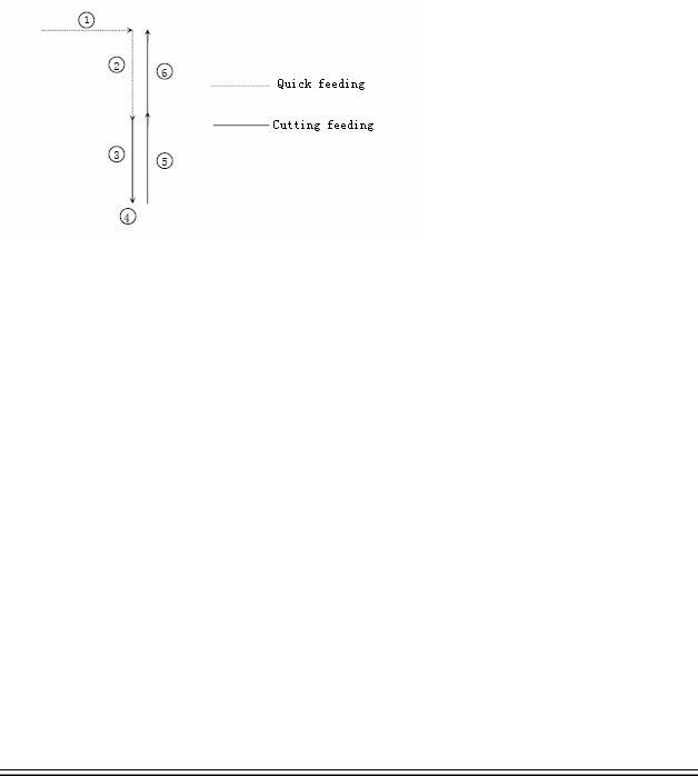
In automatic mode, press [SBK] to start the SBK function. Current program block stops after executing; press [Start] again and next block stops after executing. The SBK mode allows checking the program block by blockO.
Caution:
In G28-G30, single block also can be stopped at the center point;
The stop points of single block in fixed circle are , , in the figure below; when the single blocks of , stops, the feeding pauses and the pause indicator is on.
5.7 BDT function
In automatic mode, press [BDT] to start the BDT function, which will make the block instructions in the line after ‘/’ in the program invalid.
5.8 Stopping automatic operating
Two methods are available to stop automatic operating, i.e. enter stop command where the program will stop (M00, M01) and press the key on the operation panel to stop the machine tool.
Program stops
After executing the block with M00 or M01, the automatic operating stops, which is same to single block stop, and all mode information is saved. Start with CNC and the automatic operation can be started again.
After processing a part, the automatic operation stops.
Program ends
After executing the block with M30, the automatic operating stops, changes into reset state, and returns to program start.
Feeding pause
During automatic operation, press the [Pause] key on the operation panel, the automatic operation pauses and the indicator is on; press [Start] again to continue operating the machine tool and the pause indicator is on.
Reset
During automatic operation, press the [Reset] key on the operation panel and the system stops immediately. Here, [Reset] has the same function as emergency stop button.
- 19 -

Adtech CNC Technology Co., Ltd. |
5. Automatic operation |
|
|
|
|
6. Safe operation
6.1 Emergency stop
Press the emergency stop button on the machine tool, which will stop immediately, and all outputs such as principal axis rotation and coolant are turned off. Rotate the button clockwise to cancel emergency stop, but all outputsOmust be restarted.
Caution:
The power supply isn’t always cut off upon emergency stop. Please refer to the electrical configuration description of the
machine tool manufacturer for details;
Before releasing emergency stop, please eliminate the problems of the machine tool.
6.2 Hard limit over travel
The system alarms if the tool touches travel switch during operation. The axis in corresponding direction can’t move, and only moves in reverse direction. Before the alarm is released, the system can’t enter automatic operation normally. After investigating the alarm reason, press [Reset] to clear the alarm information.
6.3 Soft limit over travel
If the tool enters the restriction area regulated by the parameter (travel limit), the system alarms over travel, and the tool decelerates and stops. At this moment, you can move the tool to safe direction in manual mode,Oand then press [Reset] to release the alarm.
Caution:
During automatic operation, when the tool touches an axial travel switch, the tool decelerates and stops all axial motions, and only displays one over travel alarm.
During manual operation, when the tool touches an axial travel switch, the tool only decelerates and stops motion on current axis, and still moves along other axes.
When the tool is in safe position, press [Reset] to clear the alarm. Please refer to the manual of the machine tool for details. Both limit alarm and soft limit alarm have a deceleration stop, and therefore the sensing range of the limit should have sufficient space, or else the limit protection will be disabled due to over travel.
- 20 -

Adtech CNC Technology Co., Ltd. |
7. Program saving & editing |
|
|
|
|
7. Alarm and selfdiagnosis function
The system has several levels, and the alarm numbers also have different type, as follow: 0~1023: G code program running alarm info
1024~2048: System environment alarm info
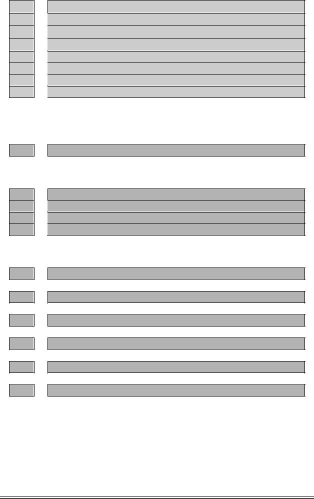
7.1 NC program execution alarm
0000 |
: |
Reset |
0001 |
: |
Prog No End |
0004 |
: |
M6Tx Abort |
0005 |
: |
Tool Invalid |
0006 |
: |
G Program Repeat Error |
0007 |
: |
G Program Number Error |
0008 |
: |
G7X8X Instruction Run Error |
0009 |
: |
Program Abend |
0010 |
: |
Appointed M01 Instruction Stop |
0011 |
: |
M98 Format Error |
0012 |
: |
Motion Run Error |
0013 |
: |
Current Program No Repair |
0014 |
: |
G Program Format Error |
0015 |
: |
M99 Instruction Abort |
0016 |
: |
Motion Abort |
0017 |
: |
Illegal char |
0018 |
: |
Noneffective Exegesis Character |
0019 |
: |
Illegal G Code |
0020 |
: |
GCode RadialOffset Num Err |
0021 |
: |
Noneffective GCode RadialOffset |
0022 |
: |
Arc Appointed Error |
0023 |
: |
Appointed Noneffective Plane |
0024 |
: |
M98 Instruction Abort |
0025 |
: |
Spindle Appointed Number Error |
0026 |
: |
MCode Instruction Abort |
0027 |
: |
Spi Appointed Err |
0028 |
: |
Motion Repeat Request |
0029 |
: |
Appointed Arc Nonentity |
0030 |
: |
Missing X Code Error |
0031 |
: |
Missing X Code Error |
- 21 -

Adtech CNC Technology Co., Ltd. |
7. Program saving & editing |
|
|
|
|
0032 |
: |
Missing X Code Error |
0033 |
: |
Missing X Code Error |
0034 |
: |
Missing X Code Error |
0035 |
: |
Missing X Code Error |
0036 |
: |
Missing X Code Error |
0037 |
: |
Missing X Code Error |
0038 |
: |
Missing X Code Error |
0039 |
: |
Missing X Code Error |
0040 |
: |
Missing X Code Error |
0041 |
: |
Missing X Code Error |
0042 |
: |
Missing X Code Error |
0043 |
: |
Missing X Code Error |
0044 |
: |
Missing X Code Error |
0045 |
: |
Missing X Code Error |
0046 |
: |
Missing X Code Error |
0047 |
: |
Missing X Code Error |
0048 |
: |
Screw Value Repeat Error |
0049 |
: |
System Abort |
0050 |
: |
Factitious return |
0051 |
: |
no parameter input |
0052 |
: |
no store address for Gcode pro num form |
7.2 System environment alarm |
|||
1024 |
: |
no |
\"return zero\ |
|
|
1. The system doesn’t perform home action after started |
|
1025 |
: |
4 - direction program limit |
|
1026 |
: |
4 + direction program limit |
|
1027 |
: |
Z - direction program limit |
|
1028 |
: |
Z + direction program limit |
|
1029 |
: |
Y - direction program limit |
|
1030 |
: |
Y + direction program limit |
|
1031 |
: |
X - direction program limit |
|
1032 |
: |
X+ direction program limit |
|
- 22 -
Adtech CNC Technology Co., Ltd. |
7. Program saving & editing |
|
|
|
|
1033 |
1034 |
1035 |
1036 |
1037 |
1038 |
1039 |
1040 |
1041 |
1042 |
1043 |
1044 |
1045 |
1046 |
1047 |
1048 |
1049 |
1051 |
1052 |
:4 - direction machine limit
:4 + direction machine limit
:Z - direction machine limit
:Z + direction machine limit
:Y - direction machine limit
:Y + direction machine limit
:X - direction machine limit
:X+ direction machine limit
The system has corresponding limit alarm. Please check corresponding limit sensor point or parameters. If hard limit occurs, and the appearance of the sensor point doesn’t has any problem, enter the diagnosis mode in manual mode and check the state of the input port in diagnosis mode. If the state is valid, please eliminate in sequence. Pull out the input IO cable and check whether the sense disappears. If yes, please check the circuit. If the problem still exists, the internal optocoupler is broken. Please contact the supplier.
:Emergency stop
Emergency stop button of the handheld box interface is valid.
External emergency stop 2 input is valid; check whether IO assignment has conflict or interference. Search for corresponding function ports in IO configuration, and then check in input diagnosis.
:X Sevor driver alarm
:Y Sevor driver alarm
:Z Sevor driver alarm
:4 Sevor driver alarm
Servo alarm; if the servo doesn’t alarm, parameter P2.001~004 setting and actual servo alarm level may
be reverse. Please modify the parameters.
The corresponding function ports are IN34~37, which can be checked in input diagnosis.
:Axis's physical line redefine
Interface axis No. set by parameter P2.45~P2.49 is specified repeatedly
:spi no to home
:workpiece no lock
:safe signal can't detect
:air no enough
:chuck signal alarm detect
7.3 Alarm processing |
|
Ü |
If alarm occurs, please refer to the alarm code to confirm the failure reason. |
Ü |
When alarm occurs, if the system isn’t reset, the alarm will constantly prompt no matter whether the |
|
alarm still exists, so as to avoid the conditions that false alarm causes system suspended, but can’t |
Ü |
find the reason. |
If the error is caused by data setting, modify the data, and then press [Reset] to clear the alarm info. |
|
- 23 -

Adtech CNC Technology Co., Ltd. |
7. Program saving & editing |
|
|
ÜWhen alarm occurs, please remove the alarm reason. Please note that several alarms may occur at the same time. Please refer to the alarm info in the Diagnosis menu for details. When the alarms are eliminated, please press [Reset] to clear the alarm ring.
7.4Self-diagnosis function
The CNC system may stop even when there is no alarm info, this may be because the system is executing certain processes. Please check with the self-diagnosis function.
The step of self-diagnosis follows:
In the main menu, press [Diagnosis] to enter the diagnosis interface;
Select [Input] to enter the input diagnosis interface, or select [Output] to enter the output diagnosis interface;
Output diagnosis: In edit mode, press the direction keys to select the output port, and press [EOB] to switch the output level of corresponding output port;
Input diagnosis: When certain input signal is valid, the corresponding area on the screen flashes.
- 24 -

Adtech CNC Technology Co., Ltd. |
8. Program saving & editing |
|
|
|
|
8. Program saving & editing
8.1 Saving the program in the memory
8.1.1 Keypad input (new program)
Create new program in the memory with the keypad, and the step follows: In the main menu, press [Edit] to enter program edit interface;
Press [File] to enter file operation interface; Select [New] to create a new file;
Enter the file name and press [EOB] to confirm and create a new program in current directory in the memory, and load into the system by default;
Select [Close] to exit [Edit] interface; In edit mode, enter the program content;
After editing all programs, press [Reset] to save the edited programs into the system memory.
8.1.2 PC serial port input
The step of transmitting files to controller through PC follows:
Set system baud rate and ID No.;
Connect to PC and run Adtech serial communication software;
Set the baud rate same as controller, and scan ID device;
Select the [Upload file to NC] button in the communication software;
Select CNC file in the popup dialog box and press [Open] button.
8.1.3 Copying processing files from USB disk
The step of copying CNC processing file to system memory through USB disk follows: In the main menu, press [Edit] to enter program edit interface;
Select [File] to enter file operation interface; Select USB disk and press [EOB] to enter;
Move the cursor to select a CNC file and then select [Copy];
Return to the root directory, locate the PROG directory in disk D, enter the directory, and select [Paste] to complete copying.
8.2 Reading programs into work area
8.2.1 Reading programs from controller into work area
The step of loading files from system memory into work area follows: Press [File] to enter file operation interface;
Select desired program, which is in PROG directory in disk D by default, press [EOB] to enter subdirectory, or press [Cancel] to exit;
Move cursor to select desired program, press [EOB] to confirm and load the program.
8.2.2 Reading programs from USB disk into work area
The step of loading files from USB disk into work area follows: Insert the USB disk;
Press [File] to enter file operation interface;
Select USB disk, move cursor to select a file in the disk, and press [EOB] to load the file.
8.3 Editing & modifying programs
The program in CNC memory can be edited with NC keypad. In the main menu, press [Edit] to enter program edit interface and edit the program in current work area (for loading program into work area, refer to 8.2). The edit mode similar to
- 25 -

Adtech CNC Technology Co., Ltd. |
8. Program saving & editing |
|
|
|
|
notepad in Windows. Move the cursor directly to locate, press keys to enter, press [EOB] to change line, and press [Delete] to delete the character where the cursor locates.
O Caution
After all operations, press Reset to save the files, and the functions base on edit mode;
CNC46XX uses new file mapping technology, and allows loading processing files that exceed its memory. Therefore, to ensure the system efficiency, you can only search and process, but can’t edit the processing files that exceed 2MB.
8.4 Deleting files
8.4.1 Deleting files in memory
Follow the step below to delete the programs in system memory: Press [File] to enter file operation interface;
Follow the prompt on the screen, select the file and press [Delete] to confirm and delete the file.
O Caution
If the program has been loaded into work area, you need to restart the system to delete the program, or else the system will report error.
The programs loaded into the work area can’t be deleted, or else the system will report error.
- 26 -
 Loading...