


ADT-8960
6-axis Motion Control Card
User’s Reference Manual
Adtech (Shenzhen) CNC Technology Co.,Ltd.
Park,MaJiaLong,Yiyuan Road, Nanshan District, Shenzhen City, China
Tel:0755-26099116 Fax: 0755-26722718
Add:5th floor,Tianxia IC Industrial
Post Code: 518052
email:export@machine-controller.com
http://www.machine-controller.com

ADT-8960 6-axis servo/ stepping motion control card
Copyrights
This User Manual contains proprietary information held by Adtech
(Shenzhen) CNC Technology Co., Ltd (“Adtech” hereafter);
stimulation, copy, photocopy or translation into other languages to
this User Manual shall be disallowed unless otherwise approved by
Adtech.
Meanwhile, Adtech doesn’t provide any kind of warranty, expression
on standing or implication. Adtech and its staffs are not liable for any
direct/ indirect information disclosure, economic loss or progress
termination caused by this User Manual and the product information
inside.
All the contents in this User Manual may be changed without any
notice.
Trademark
All the product names introduced in this User Manual are only for
identification purpose, while they may belong to other various
trademarks or copyrights, such as:
※ INTEL and PENTIUM are trademarks of INTEL Company;
※ WINDOWS and MS-DOS trademarks of MICROSOFT
Company;
※ ADT-8960 is the trademark of Adtech;
※ Other trademarks belong to their corresponding registered
companies.
- 1 -
www.machine-controller.com

ADT-8960 6-axis servo/ stepping motion control card
All copyrights reserved by Adtech (Shenzhen) CNC Technology Co.,
Ltd
Version Upgrading Record
Version Revised in Descriptions
V7.0 2010/01/04 The seventh version
Remark: The three digits in the version number respectively
mean:
Hardware version number Major version number Minor version number
- 2 -
www.machine-controller.com

ADT-8960 6-axis servo/ stepping motion control card
Contents
CHAPTER 1 GENERAL INFORMATION....................................... - 6 -
INTRODUCTION.......................................................................- 6 -
MAIN FEATURES......................................................................- 6 -
APPLICATIONS .........................................................................- 7 -
CHAPTER 2 HARDWARE INSTALLATION .................................. - 8 -
PARTS .........................................................................................- 8 -
INSTALLATION.........................................................................- 8 -
CHAPTER 3 ELECTRICAL CONNECTION..................................- 9 -
J1 LINE..........................................................................................- 9 -
J2 LINE........................................................................................- 14 -
CONNECTION FOR PULSE/ DIRECTION INPUT SIGNAL.....- 16 -
CONNECTION FOR ENCODER INPUT SIGNAL.....................- 17 -
CONNECTION FOR DIGITAL INPUT.......................................- 18 -
CHAPTER 4 SOFTWARE INSTALLATION.................................. - 21 -
DRIVE INSTALLATION IN WIN98............................................- 21 -
DRIVE INSTALLATION UNDER WINXP.................................- 23 -
CHAPTER 5 FUNCTIONS ............................................................... - 26 -
PULSE OUTPUT METHOD.............................................................- 26 -
HARDWARE LIMIT SIGNAL..........................................................- 26 -
LINEAR INTERPOLATION..............................................................- 26 -
QUANTITATIVE VELOCITY............................................................- 28 -
EXTERNAL SIGNAL DRIVING........................................................- 28 -
POSITION LOCK............................................................................- 28 -
MANUAL DECELERATION.............................................................- 28 -
HARDWARE CACHE .....................................................................- 28 -
- 3 -
www.machine-controller.com

ADT-8960 6-axis servo/ stepping motion control card
CHAPTER 6 LIST OF ADT8960 BASIC LIBRARY FUNCTIONS.- 29
CHAPTER 7 DETAILS OF ADT8960 BASIC LIBRARY
FUNCTIONS....................................................................................... - 34 -
CATEGORY OF BASIC PARAMETER SETTING....................................- 34 -
CATEGORY OF DRIVE STATUS CHECK..........................................- 38 -
CATEGORY OF MOVEMENT PARAMETER SETTING .......................- 39 -
CATEGORY OF MOTION PARAMETER CHECK................................- 42 -
CATEGORY OF DRIVE ..................................................................- 44 -
CATEGORY OF INPUT/OUTPUT................................................- 48 -
CATEGORY OF COMPOSITE DRIVING ...........................................- 48 -
CATEGORY OF EXTERNAL SIGNAL DRIVING ................................- 54 -
CATEGORY OF POSITION LOCK....................................................- 55 -
CATEGORY OF HARDWARE CACHE..............................................- 56 -
MANUAL DECELERATION FUNCTION...........................................- 60 -
CHAPTER 8 GUIDE TO MOTION CONTROL FUNCTION
LIBRARY............................................................................................ - 63 -
CHAPTER 9 BRIEFING ON MOTION CONTROL
DEVELOPMENT............................................................................... - 67 -
C
ARD INITIALIZATION
S
PEED SETTING
...........................................................- 67 -
........................................................................- 67 -
CHAPTER 10 PROGRAMMING SAMPLES IN MOTION
CONTROL DEVELOPMENT.......................................................... - 69 -
VB PROGRAMMING SAMPLES ......................................................- 69 -
VC PROGRAMMING SAMPLES ......................................................- 95 -
CHAPTER 11 NORMAL FAILURES AND SOLUTIONS........... - 122 -
M
OTOR SERVICE FAILURE.........................................................- 122 -
- 4 -
www.machine-controller.com

ADT-8960 6-axis servo/ stepping motion control card
ABNORMAL SWITCH INPUT........................................................- 124 -
- 5 -
www.machine-controller.com

ADT-8960 6-axis servo/ stepping motion control card
Chapter 1 General information
INTRODUCTION
ADT8940A1 Card is a kind of high-performance 4-axis servo/ stepping control card
based on PCI bus and supporting Plug & Play, while one system can support up to
16 control cards and control up to 64 lines of servo/ stepping motors.
Pulse output method may be single pulse (pulse + direction) or double pulse
(pulse+pulse), with the maximum pulse frequency of 2MHz. Advanced technologies
are applied to ensure the frequency tolerance is less than 0.1% despite of high
output frequency.
It supports 2-4 axis of linear interpolation, with the maximum interpolation speed of
1MHz.
Position management is realized through two up/ down counters, one used to
manage logical positions of internally driven pulse output, and the other used to
receive external input, with encoder or grating ruler inputted through A/ B phase as
the input signal.
Counters are up to 32 digits, specially, the range is 2,147,483,648~+2,147,483,647.
The system also provides DOS/WINDOWS95/98/NT/2000/XP/WINCE development
libraries and enable software development in VC++, VB, BC++, LabVIEW, Delphi, and
C++Builder.
MAIN FEATURES
32-digit PCI bus, enabling Plug & Play
All the input and output are under photoelectric coupler isolation, with
strong resistance to disturbance.
6-axis servo/ stepping motor control, with every axis able to move
independently without mutual effects.
Frequency tolerance for pulse output is less than 0.1%.
The maximum pulse output frequency is 2MHz.
Pulse output may be single (pulse+ direction) or double(pulse+ pulse)
All the 6 axes have position feedback input in 32-digit counting, giving the
maximum counting range of -2,147,483,648~ +2,147,483,647.
Trapezoidal acceleration/ deceleration
2-6 axis linear interpolation.
Maximum interpolation speed: 1MHz.
Handwheel and external signal operation
h
ardware caching.
- 6 -
, position lock, large-capacity
www.machine-controller.com
of

ADT-8960 6-axis servo/ stepping motion control card
Real-time reading of logical, real and driving speeds during movement
32 channels digital input/32 channels digital output with optical coupling isolation,
including two positive/negative limiting signals of each axis Read the logical
position, actual position, driving speed, acceleration and driving state in real time
during motion
general input
Up to 16 control cards supported within one system.
DOS/WINDOWS95/98/NT/2000/XP/WIN CE supported.
Two limit input for each axis may be set as Nil and work as
APPLICATIONS
Multi-axis engraving system
Robot system
Coordinate measurement system
PC-based CNC system
- 7 -
www.machine-controller.com

ADT-8960 6-axis servo/ stepping motion control card
Chapter 2 Hardware installation
PARTS
1. ADT-8960 User Manual (this manual)
2. ADT-8960 6-axis PCI bus high-performance motion control card
3. ADT-8960 user CD
4. ADT-D62GG 2 pcs
5. ADT-9162 connecting plate 2 pcs
6. DB64 64pin cable 1 pc
7. ADT-9164 connecting plate 1 pc
INSTALLATION
1. Switch off the computer power supply (for ATX supply case, switch off
the overall power)
2. Open the back cover of the computer case
3. Insert ADT-8960 into an available PCI slot
4.
Ensure the golden finger of
and then fasten card with screws
5. Connect one end of the D62GG cable to J1 interface of motion card
and the other end to terminal block ADT_9162.
6. Check whether it is necessary to install J2 interface cable. To install J2
if necessary:
(1) Connect one end of ADT-DB64 to J2 of motion card and the other
end to P2 of ADT-DB64;
(2) Fix the ADT-DB64 on the rear side of the enclosure;
(3) Connect ADT-D62GG to P2 of the transition board and
ADT-D62GG.
ADT-8960 has been fully inserted the slot
- 8 -
www.machine-controller.com

ADT-8960 6-axis servo/ stepping motion control card
Chapter 3 Electrical connection
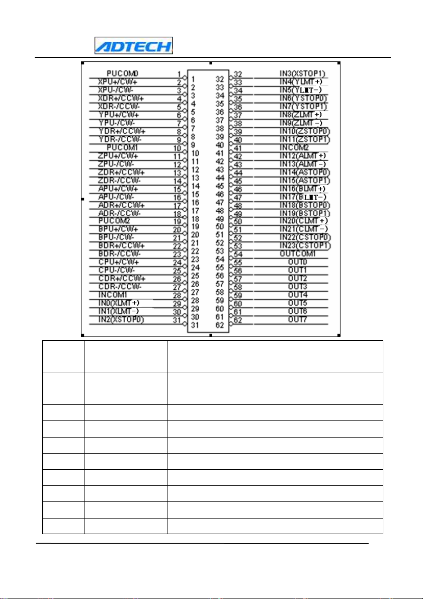
There are two input/ output interfaces inside an ADT8960 card, whereby J1 is for 62-pin
socket and J2 is for 62-pin.
J1 is the signal cable for pulse output of X, Y, Z and A, B, C axis, switch amount input
and switch amount output (OUT0-OUT7); J2 is the signal cable for encoder input and
switch amount input of X, Y, Z and A, B, C axis; switch amount input and switch amount
output (OUT8-OUT15).
Signals are defined as follows:
J1 line
- 9 -
www.machine-controller.com
ADT-8960 6-axis servo/ stepping motion control card
Line
number
Signal Introduction
1 PUCOM0
2 XPU+/CW+ X pulse signal +
3 XPU-/CW- X pulse signal 4 XDR+/CCW+ X direction signal +
5 XDR-/CCW- X direction signal 6 YPU+/CW+ Y pulse signal +
7 YPU-/CW- Y pulse signal 8 YDR+/CCW+ Y direction signal +
9 YDR-/CCW- Y direction signal -
Used for single-port input, not available for external
power supply
- 10 -
www.machine-controller.com

ADT-8960 6-axis servo/ stepping motion control card
10 PUCOM1
11 ZPU+/CW+ Z pulse signal +
12 ZPU-/CW- Z pulse signal 13 ZDR+/CCW+ Z direction signal +
14 ZDR-/CCW- Z direction signal 15 APU+/CW+ A pulse signal +
16 APU-/CW- A pulse signal 17 ADR+/CCW+ A direction signal +
18 ADR-/CCW- A direction signal -
19 PUCOM2
20
BPU+/CW+
Used for single-port input, not available for external
power supply
Used for single-port input, not available for external
power supply
B pulse signal +
21
22
23
24
25
26
27
28
29
30
BPU-/CW-
BDR+/CCW+
BDR-/CCW-
CPU+/CW+
CPU-/CW-
CDR+/CCW+
CDR-/CCW-
INCOM1
IN0(XLMT+)
IN1(XLMT-)
B pulse signal -
B direction signal +
B direction signal -
C pulse signal +
C pulse signal -
C direction signal +
C direction signal -
IN0-11, able to work as general input signal
Positive direction of the Limit Signal for X,able to
work as general input signal
Negative direction of the Limit Signal for X able to
work as general input signal
- 11 -
www.machine-controller.com

31
32
33
34
35
36
37
38
39
40
41
IN2(XSTOP0)
IN3(XSTOP1)
IN4(YLMT+)
IN5(YMT-)
IN6(YSTOP0)
IN7(YSTOP1)
IN8(ZLMT+)
IN9(ZLMT-)
IN10(ZSTOP0)
IN11(ZSTOP1)
INCOM2
ADT-8960 6-axis servo/ stepping motion control card
Origin signal 0 for X, Manually decelerate, able to
work as general input signal
STOP1- signal for X,able to work as general input
signal
Positive direction of the Limit Signal for Y,able to
work as general input signal
Negative direction of the Limit Signal for Y able to
work as general input signal
Origin signal 0 for Y, Manually decelerate, able to
work as general input signal
STOP1- signal for Y,able to work as general input
signal
Positive direction of the Limit Signal for Z,able to
work as general input signal
Negative direction of the Limit Signal for Z able to
work as general input signal
Origin signal 0 for Z, Manually decelerate, able to
work as general input signal
STOP1- signal for Z,able to work as general input
signal
IN12-23 Input general port
42
43
44
45
IN12(ALMT+)
IN13(ALMT-)
IN14(ASTOP0)
IN15(ASTOP1)
Positive direction of the Limit Signal for A,able to
work as general input signal
Negative direction of the Limit Signal for A able to
work as general input signal
Origin signal 0 for A, Manually decelerate, able to
work as general input signal
STOP1- signal for A,able to work as general input
signal
- 12 -
www.machine-controller.com

46
47
48
49
50
51
52
53
54
55
56
57
58
59
60
61
IN16(BLMT+)
IN17(BLMT-)
IN18(BSTOP0)
IN19(BSTOP1)
IN20(CLMT+)
IN21(CLMT-)
IN22(CSTOP0)
IN23(CSTOP1)
OUTCOM1
OUT0
OUT1
OUT2
OUT3
OUT4
OUT5
OUT6
ADT-8960 6-axis servo/ stepping motion control card
Positive direction of the Limit Signal for B,able to
work as general input signal
Negative direction of the Limit Signal for B able to
work as general input signal
Origin signal 0 for B, Manually decelerate, able to
work as general input signal
STOP1- signal for B,able to work as general input
signal
Positive direction of the Limit Signal for C,able to
work as general input signal
Negative direction of the Limit Signal for C able to
work as general input signal
Origin signal 0 for C, Manually decelerate, able to
work as general input signal
STOP1- signal for C,able to work as general input
signal
OUT0-OUT7 general port
Digital Output.
62
OUT7
- 13 -
www.machine-controller.com
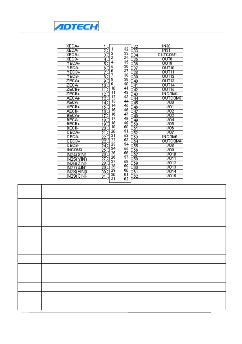
J2 line
Line
number
1
2
3
4
5
6
7
8
9
10
11
12
Signal
XECA+
XECA-
XECB+
XECB-
YECA+
YECA-
YECB+
YECB-
ZECA+
ZECA-
ZECB+
ZECB-
ADT-8960 6-axis servo/ stepping motion control card
Introduction
X-axis encoder A-phase input+
X-axis encoder A-phase input X-axis encoder B-phase input +
X-axis encoder B-phase input -,
Y-axis encoder A-phase input+
Y-axis encoder A-phase input Y-axis encoder B-phase input +
Y-axis encoder B-phase input -,
Z-axis encoder A-phase input+
Z-axis encoder A-phase input Z-axis encoder B-phase input +
Z-axis encoder B-phase input -,
- 14 -
www.machine-controller.com

13
14
15
16
17
18
19
20
21
22
23
24
25
26
27
28
29
30
31
32
33
34
35
36
37
38
AECA+
AECA-
AECB+
AECB-
BECA+
BECA-
BECB+
BECB-
CECA+
CECA-
CECB+
CECB-
INCOM3
IN24(XIN)
IN25(YIN)
IN26(ZIN)
IN27(AIN)
IN28(BIN)
IN29(CIN)
IN30
IN31
OUTCOM2
OUT8
OUT9
OUT10
OUT11
39 OUT12
40 OUT13
41 OUT14
42 OUT15
ADT-8960 6-axis servo/ stepping motion control card
A-axis encoder A-phase input+
A-axis encoder A-phase input A-axis encoder B-phase input +
A-axis encoder B-phase input -,
B-axis encoder A-phase input+
B-axis encoder A-phase input B-axis encoder B-phase input +
B-axis encoder B-phase input -,
C-axis encoder A-phase input+
C-axis encoder A-phase input C-axis encoder B-phase input +
C-axis encoder B-phase input -,
IN24-IN31 General port
Input points for switch amount(X-axis position lock)
Input points for switch amount(Y-axis position lock)
Input points for switch amount(Z-axis position lock)
Input points for switch amount(A-axis position lock)
Input points for switch amount(B-axis position lock)
Input points for switch amount(C-axis position lock)
Input points for switch amount
Input points for switch amount(All axis stop)
OUT8-OUT15 General port
Output points for switch amount
Output points for switch amount
Output points for switch amount
Output points for switch amount
Output points for switch amount
Output points for switch amount
Output points for switch amount
Output points for switch amount
- 15 -
www.machine-controller.com

ADT-8960 6-axis servo/ stepping motion control card
43 INCOM4
44 OUTCOM3
45 I/O0
46 I/O1
47 I/O2
48 I/O3
49 I/O4
50 I/O5
51 I/O6
52 I/O7
53 INCOM5
54 OUTCOM4
55 I/O8
56 I/O9
57 I/O10
58 I/O11
59 I/O12
60 I/O13
61 I/O14
62 I/O15
Remark: In case an encoder is used for general input signals, XECA+、、、、XECB+、
YECA+、、、、YECB+、、、、ZECA+、、、、ZECB+、、、、AECA+、、、、AECB+、、、、BECA+、、、、BECB+、、、、CECA+、
CECB+ will be respectively used as public ports of corresponding input signals.
Voltage at the public ports can only be +5V
power supply, users must serially connect a 1K resistance. Please refer to the
following digital input connection part for wiring method.
I/O0-I/O7 as Input public port
I/O0-I/O7 as output public port
Input/output(X axis manually CW)
Input/output(X axis manually CCW)
Input/output(Y axis manually CW)
Input/output(Y axis manually CCW)
Input/output(Z axis manually CW)
Input/output(Z axis manually CCW)
Input/output(A axis manually CW)
Input/output(A axis manually CCW)
I/O8-I/O15 as Input public port
I/O8-I/O15 as output public port
Input/output(B axis manually CW)
Input/output(B axis manually CCW)
Input/output(C axis manually CW)
Input/output(C axis manually CCW)
Input/output
Input/output
Input/output
Input/output
; in case of using an external+12V
...
、
、、
、
、、
CONNECTION FOR PULSE/ DIRECTION INPUT SIGNAL
Pulse output is in differential output.
May be conveniently connected with a stepping/ servo driver
- 16 -
www.machine-controller.com

ADT-8960 6-axis servo/ stepping motion control card
The following figure shows open-collector connection between pulse and direction.
Stepping motor driver
The following figure shows differential-output connection between pulse and direction
signals; this method is recommended as it is differential connection with strong
resistance to disturbance.
Stepping motor driver
Servo motor driver
Remark: Refer to Appendix A for wiring maps of stepping motor drivers, normal servo
motor driver and terminal panel.
CONNECTION FOR ENCODER INPUT SIGNAL
- 17 -
www.machine-controller.com

Wiring map for an open
-
collect output
-
type encoder. For
+5V power supply, R is not required; for +12V power
external power supply
ADT-8960 6-axis servo/ stepping motion control card
Encoder
supply, R= 1KΩ; and for +24V power supply, R= 2KΩ
Encoder
Wiring map for a differential-driver output-type encoder
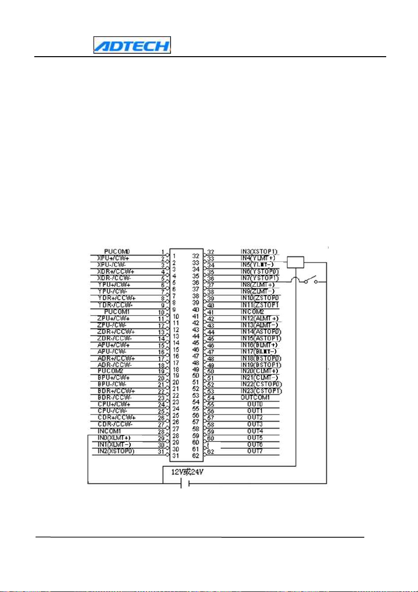
CONNECTION FOR DIGITAL INPUT
Internal circuit
Remark:
(1) Public terminal for IN0-IN11: INCOM1
Public terminal for IN12-IN23: INCOM2
Public terminal for IN24-IN31: INCOM3
Public terminal for I/O0-I/O7: INCOM4
Public terminal for I/O8-I/O15: INCOM5
K1 is for approach switch or
photoelectric switch, and K2 is for
normal mechanical switch
VEXT is anode of
EXT_GND is cathode
of external power
supply
- 18 -
www.machine-controller.com
or
ADT-8960 6-axis servo/ stepping motion control card
(2) To make input signals effective, users shall make sure: firstly, the photoelectric
coupling public ports for corresponding input signals (INCOM1, INCOM2, INCOM3,
INCOM4 or INCOM5) have been connected with anodes of 12V/ 24V power supply;
secondly, one port of the normal switch or earthing cable of the approach switch has
been connected with the cathode (earthing cable); and lastly, the other port of the
normal switch or the control of the approach switch has been connected with the
input port corresponding by the terminal panel.
(3) The following is the actual wiring map of power supply from normal switch and
approach switch to photoelectric coupling public ports, through external power
supply. (take J1 as example)
- 19 -
www.machine-controller.com
ADT-8960 6-axis servo/ stepping motion control card
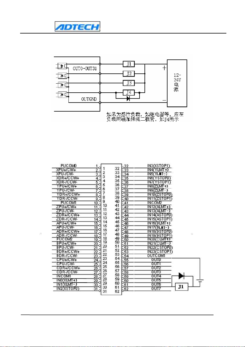
Connection of digital output.
- 20 -
www.machine-controller.com
ADT-8960 6-axis servo/ stepping motion control card
Chapter 4 Software installation
ADT8960
WinXP, but in case of DOS, no drive is required to be installed.
The following part takes Win98 and WinXP for example, and users may refer to other
operating systems.
Drive for the control card is located in the Drive/ ControlCardDrive folder within the CD,
and the drive file is named as ADT8960.INF.
DRIVE INSTALLATION IN WIN98
card must be used with drive installed under Win95/ Win98/ NT/ Win2000/
The following part takes Win98 Professional Version as example to indicate
installation of the drive; other versions of Win98 are similar.
After attaching the ADT8960 card to the PCI slot of a computer, a user shall log in
as administrator to the computer; upon display of the initial interface, the computer
shall notify “Found new hardware” as follows:
Just click “Next” to display the following picture:
- 21 -
www.machine-controller.com

ADT-8960 6-axis servo/ stepping motion control card
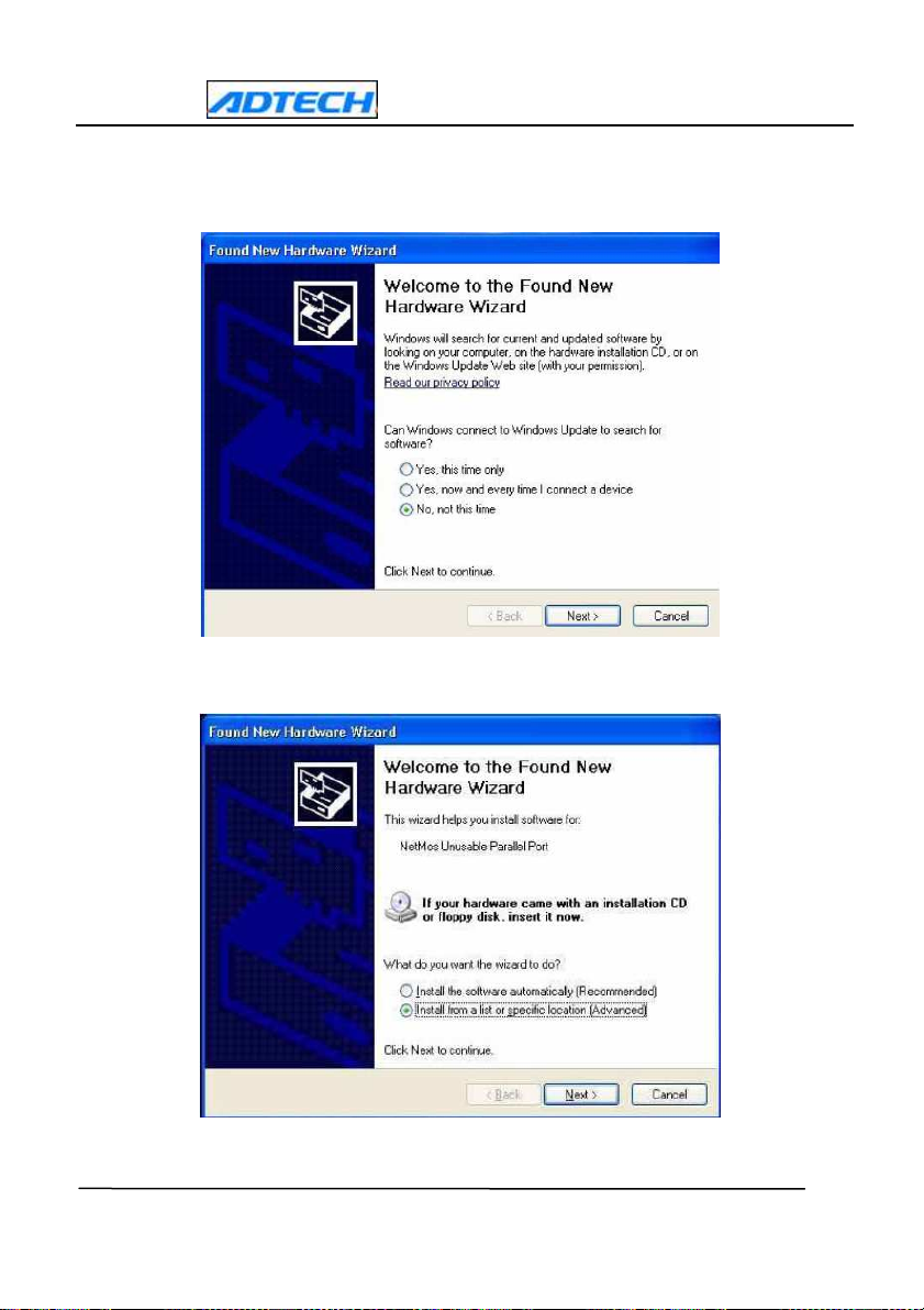
Click again “Next” to display the following picture:
Then select “Specify a location” and Click again “Next” and
select DevelopmentPackage/ Drive/ CardDrive and find the ADT8960.INF file, then click
“OK” to display the following interface:
- 22 -
www.machine-controller.com
Click “Browse” button to

Click
“Next” to display the following picture:
ADT-8960 6-axis servo/ stepping motion control card
Finally click “Finish” to complete installation.
DRIVE INSTALLATION UNDER WINXP
- 23 -
www.machine-controller.com
Installation under
ADT-8960 6-axis servo/ stepping motion control card
WinXP
is similar to that under Win98, specifically:
- 24 -
www.machine-controller.com

ADT-8960 6-axis servo/ stepping motion control card
Click “Browse” button to select Drive/ CardDrive and find the ADT8960.INF file, then
click “Next” to display the following interface:
Then click “Finish” to complete installation.
- 25 -
www.machine-controller.com
Pulse/ direction is set on the positive logical level
Puls
Independent 2
-
puls
Output signal waveform
PU/CW signal
+Direction
Low level
Low level
Lo
w level
Hi level
+Direction
-
Direction
1-pulse 1
-
direction
ADT-8960 6-axis servo/ stepping motion control card
Chapter 5 Functions
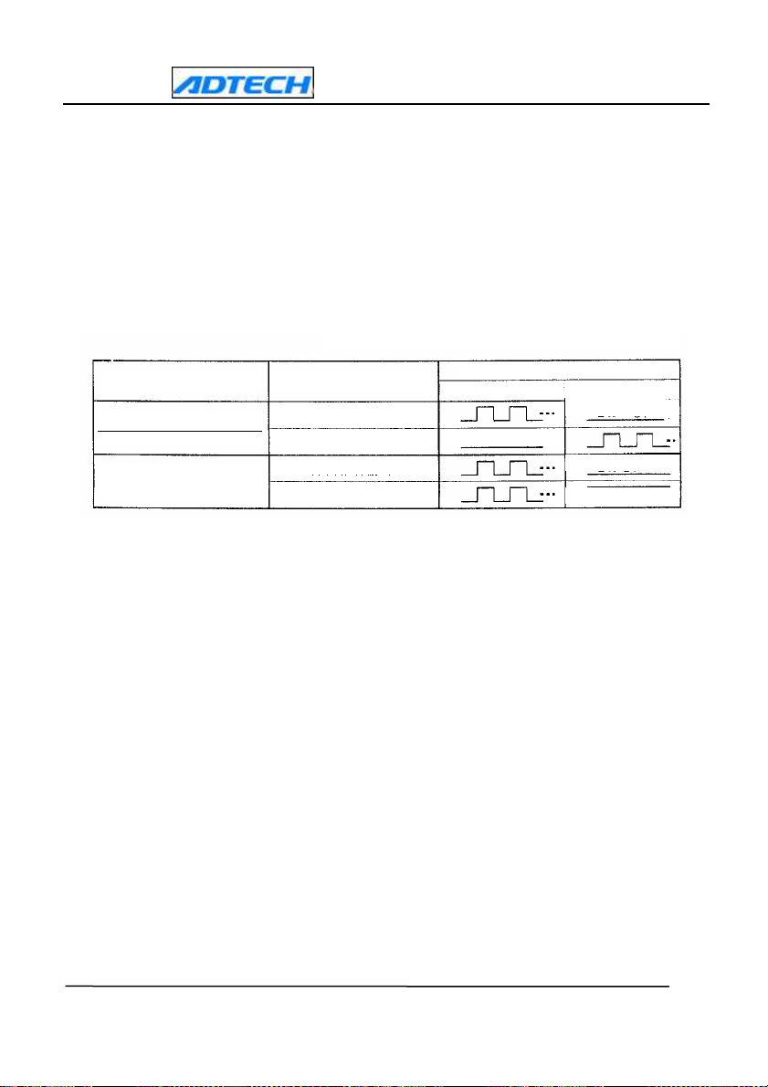
Pulse output method
Pulse output may be realized through either independent 2-pulse or 1-pulse. In
case of independent 2-pulse, the positive direction drive has PU/CW outputting drive
pulses, and the negative direction drive has DR/CCW outputting drive pulses. In
case of 1-pulse, PU/CW outputs drive pulse and DR/CCW outputs direction signals.
Hardware limit signal
Hardware limit signals LMT+ and LMT- are respectively to limit the
input signals outputted by drive pulse along positive and negative
directions, which can be set as “effective”, “ineffective” with high/low
levels. Actually “effective” or “ineffective” can be set for positive limit and
negative limit individually. In case “ineffective” is selected, they may
work as ordinary input points.
Hard limit signals STOP0 and STOP1 are input signals that may
realize hardware termination for all axis drive and may be set as
“effective”, “ineffective” as well as termination method for high/low levels.
In case “ineffective” is selected, they may work as general input points.
Besides, they, when working as drive for interpolation, are effective for
the minimum interpolation axis only.
Linear interpolation
This card may work for 2~6 axes linear interpolation under the modified
method of point-by-point comparison, which can ensure uniform pulse along
Drive direction
-Direction
DR/CCW signal
- 26 -
www.machine-controller.com

ADT-8960 6-axis servo/ stepping motion control card
the long axis, giving the precision within one pulse.
Firstly, take the axis outputting the maximum pulses among the axes
joining interpolation as the long axis, and proportionally distribute for the
rest axes. Speed control applies only to speed of the long axis.
For example, (1-X axis, 2-Y axis, 3-Z axis, and 4-W axis).
Take four axes for linear interpolation, while Axis 1 outputs 1000
pulses, Axis 2 outputs 500, Axis 3 outputs 250 and Axis outputs 2000.
X axis
Y axis
Z axis
W axis
From the above figure, A axis shall be the long axis, and the rest axes
proportionally share the pulses.
Setting of interpolation speed takes the minimum speed of an axis
among the joined axes as the benchmark, for example, if Axis 2 and Axis 3
join linear interpolation, the interpolation speed will be determined by
speed of Axis 2. moreover, speed of interpolation is only half of the single
axis.
For example, Axis 2 and Axis 3 work for two-axis linear interpolation,
with Axis 2 outputs 10000 pulses along positive direction and Axis 3
outputs 5000 pulses along negative direction, which means Axis 2 is the
long axis.
set_startv(0,2,1000);
set_speed(0,2,1000);
inp_move2(0,2,3,10000,-5000);
After execution of the above program, Axis 2 will send 10000 pulses in
the frequency of 1000/2=500Hz, while frequency of Axis 3 shall be
- 27 -
www.machine-controller.com

ADT-8960 6-axis servo/ stepping motion control card
500*5000/10000=250Hz.
If speed of Axis 2 realizes trapezoidal acceleration/deceleration,
interpolation will also follow such trapezoidal acceleration/deceleration.
Quantitative velocity
The velocity may change during motion, so as to control the speed
and track more flexibly and effectively. Refer to the settings of relative
functions, set_atartv, set_speed, set_acc and so on for change of velocity.
External signal driving
External signal driving is the motion controlled by external signals
(handwheel or switch). It is mainly used in the manual debugging of
machines and teaching system. When the external signal driving is
enabled, use the handwheel or mechanical switch to control the pulse and
thus the motion. When the external signal function is not to be used,
disable the external signal driving.
Position lock
Realize hardware position lock function with the designated IN signal
on each axis. With one lock signal, the current position, either logical or
actual, of all axes can be locked. The position lock is useful in measuring
system.
Manual deceleration
Realize manual deceleration function with the designated IN signal on
each axis. The manual deceleration point can be set on each axis
separately. When reaching the point, it will decelerate to the designated
speed automatically. The origin can be searched at the designated speed,
while the origin signal should be triggered externally.
Hardware Cache
With the large capacity hardware cache function, interpolation data
can be saved in the buffer area before motion to be processed in advance,
ensuring continuous output of pulse and enabling smooth and consecutive
motion. Therefore, the processing precision can be effectively promoted.
The memory space for FIFO is as high as 2MB.
- 28 -
www.machine-controller.com

Chapter 6 List of ADT8960 basic library functions
List of library functions
Func
tion
type
Basi
para
mete
Che
for
drive
statu
Function name Function description
adt8960_initial Initialize card
set_pulse_mode Set pulse mode
set_limit_mode Set limit mode
set_stop0_mode Set stop mode
c
set_stop1_mode Set stop mode
rs
set_delay_time Delay status
set_suddenstop_mode Hardware stop
set_ad_mode
get_status
ck
get_inp_status
get_delay_status Delay status
s
ADT-8960 6-axis servo/ stepping motion control card
P
a
g
e
2
9
2
9
3
0
3
0
3
1
3
1
3
1
Acceleration/deceleratio
n mode
Get status of single axis
drive
Get status of
interpolation
3
2
3
2
3
2
3
3
- 29 -
www.machine-controller.com

Mov
eme
nt
para
mete
r
setti
ng
Che
ck
for
moti
on
para
Driv
e
ADT-8960 6-axis servo/ stepping motion control card
get_hardware_ver Hardware version
set_acc Set acceleration
set_acac
Set acceleration change
rate
set_startv Set starting speed
set_speed Set drive speed
set_command_pos
Set logical position
counter
set_actual_pos Set real position counter
set_symmetry_speed Set symmetry speed
set_io_mode
General IN/OUT point
position
get_command_pos Get logical position
get_actual_pos Get real position
get_speed Get drive speed
get_out Get output point
get_ad Get acceleration
pmove
Single-axis quantitative
drive
3
3
3
3
3
4
3
4
3
4
3
4
3
5
3
5
3
6
3
6
3
6
3
7
3
7
3
7
3
8
- 30 -
www.machine-controller.com

Swit
ch
I/O
cate
gory
Com
posit
e
drivi
ng
ADT-8960 6-axis servo/ stepping motion control card
continue_move Continue moving
dec_stop Deceleration stop
sudden_stop Sudden stop
inp_move2
inp_move3
inp_move4
inp_move5
inp_move6
2-axis linear
interpolation
3-axis linear
interpolation
4-axis linear
interpolation
5-axis linear
interpolation
6-axis linear
interpolation
read_bit Read single input point
write_bit Single output point
symmetry_relative_move
symmetry_absolute_move
symmetry_relative_line2
Symmetric relative
movement of single axis
Symmetric absolute
movement of single axis
Relative movement of
2-axis symmetric linear
interpolation
3
8
3
8
3
9
3
9
3
9
4
0
4
0
4
1
4
1
4
1
4
2
4
2
4
3
- 31 -
www.machine-controller.com

Exte
rnal
puls
ADT-8960 6-axis servo/ stepping motion control card
symmetry_absolute_line2
symmetry_relative_line3
symmetry_absolute_line3
symmetry_relative_line4
symmetry_absolute_line4
symmetry_relative_line5
symmetry_absolute_line5
symmetry_relative_line6
symmetry_absolute_line6
manual_pmove
Absolute movement of
2-axis symmetric linear
interpolation
Relative movement of
3-axis symmetric linear
interpolation
Absolute movement of
3-axis symmetric linear
interpolation
Relative movement of
4-axis symmetric linear
interpolation
Absolute movement of
4-axis symmetric linear
interpolation
Relative movement of
5-axis symmetric linear
interpolation
Absolute movement of
5-axis symmetric linear
interpolation
Relative movement of
6-axis symmetric linear
interpolation
Absolute movement of
6-axis symmetric linear
interpolation
Quantitative drive
function of external
signal
4
3
4
4
4
4
4
5
4
5
4
6
4
6
4
7
4
7
4
8
- 32 -
www.machine-controller.com

Posit
ion
lock
Hard
ware
cach
e
ADT-8960 6-axis servo/ stepping motion control card
Continuous drive
manual_continue
function of external
signal
manual_disable
Disable external signal
drive
set_lock_position Set position lock mode
get_lock_status Get lock status
get_lock_position Get lock position
clr_lock_status Clear lock position
fifo_inp_move1 1-axis FIFO
fifo_inp_move2 2-axis FIFO
fifo_inp_move3 3-axis FIFO
fifo_inp_move4 4-axis FIFO
fifo_inp_move5 5-axis FIFO
fifo_inp_move6 6-axis FIFO
reset_fifo Reset FIFO
read_fifo_count Read FIFO
4
8
4
8
4
9
4
9
4
9
5
0
5
0
5
0
5
1
5
1
5
2
5
2
5
3
5
3
- 33 -
www.machine-controller.com

Man
ual
dece
lerati
on
ADT-8960 6-axis servo/ stepping motion control card
read_fifo_empty Read FIFO
read_fifo_full Read FIFO
set_dec_mode
set_dec_pos1
Set manual
deceleration mode
Set manual
deceleration point
Rest position after
set_dec_pos2
arriving at deceleration
point
clr_dec_status
get_dec_status
set_end_speed
Clear manual
deceleration status
Get manual
deceleration status
Set the ending speed
5
3
5
3
5
5
5
5
5
5
5
6
5
6
5
6
Chapter 7 Details of ADT8960 basic library functions
Category of basic parameter setting
1.1 Initialize card
int adt8960_initial(void)
Function:
To initialize the card
Return:
(1)>0, indicating the amount of installed ADT8960 cards; In
case the Return is 3, the available card numbers shall be 0, 1,
and 2;
- 34 -
www.machine-controller.com

Negative logic pulse:
Pulse/ direction are both of positive logic setting
Pulse output method
pulse
Drive direction
Output signal waveform
DR/CCW signal
Positive drive output
Negative drive output
Low level
Low level
Low level
Hi level
Positive drive output
Negative drive output
1-pulse method
ADT-8960 6-axis servo/ stepping motion control card
(2) =0, indicating no installation of ADT8960 card;
(3)<0, indicating no installation of service if the value is -1 or
PCI bus failure if the value is -2.
Note: Initialization functions are preliminary conditions to call
other functions thus must be called firstly so as to verify available
cards and initialize some parameters.
1.2 Get output pulse mode
int set_pulse_mode(int cardno, int axis, int value,int logic,int
dir_logic)
Function:
Parameters:
To set the output pulse mode
cardno Card number
axis
Axis number (1-6)
Value 0: Pulse+Pulse method 1: Pulse+direction method
Independent 2-
logic
pulse
0: Positive logic pulse
1: Negative logic
Positive logic pulse:
dir-logic 0: Positive logic direction of output signal 1:
- 35 -
www.machine-controller.com

ADT-8960 6-axis servo/ stepping motion control card
Negative logic direction of output signal
Dir_logic Output to positive
direction
Output to negative
direction
0 Low Hi
1 Hi Low
Return:
0: Correct
1: Wrong
Default mode: Pulse + direction, with positive logic pulse and
positive logic direction input signal
1.3 Set mode of nLMT signal input along positive/negative
direction
int set_limit_mode(int cardno, int axis, int v1,int v2,int logic)
Function:
To set mode of nLMT signal input along positive/negative
direction
Parameters:
cardno Card number
axis
Axis number (1-6)
v1
0: Positive limit is effective
1: Positive limit is
ineffective
v2
0: Negative limit is effective
1: Negative
limit is ineffective
logic
0: Low level is effective
1: High level is
effective
Return:
0: Correct
1: Wrong
Default mode: positive and negative limits with low level are
effective
1.4 Set mode of stop0 input signal
int set_stop0_mode(int cardno, int axis, int v,int logic)
Function:
- 36 -
www.machine-controller.com

ADT-8960 6-axis servo/ stepping motion control card
To set mode of stop0 input signal
Parameters:
cardno Card number
axis
Axis number (1-6)
v
logic
0: stop0 is ineffective
0: Low level is effective
1: stop0 is effective
effective
Return:
Default mode: Stop 0 is ineffective
1.5 Set mode of stop1 input signal
0: Correct
1: Wrong
int set_stop1_mode(int cardno, int axis, int v,int logic)
Function:
Parameters:
To set mode of stop1 input signal
cardno Card number
axis
Axis number (1-6)
v
logic
0: stop0 is ineffective
0: Low level is effective
1: stop0 is effective
effective
Return:
0: Correct
1: Wrong
Default mode: stop1 is ineffective
1.6 Delay time
int set_delay_time(int cardno,long time)
Function:
To delay the time
Parameters:
time Delay time
maximum.
cardno Card number
Return: 0: Correct 1: Wrong
Note:
The time unit is 1/8us, with the maximum integer value as its
- 37 -
www.machine-controller.com
1: High level is
1: High level is

ADT-8960 6-axis servo/ stepping motion control card
1.7 Set stop using the hardware
int set_suddenstop_mode(int cardno,int v,int logical)
Function:
To set stop sing the hardware
Parameters:
v 0: ineffective 1: effective
logical 0: low level effective 1: high level effective
panel (IN31)
1.8 Set acceleration/deceleration mode
int set_ad_mode(int cardno,int axis,int mode)
cardno Card number
Return: 0: Correct
Note: Hardware stop signals are assigned to use the 33 pin at the P2 terminal
1: Wrong
Function: To select the acceleration/deceleration mode, trapezoid or
S-type
Parameters:
cardno Card number
axis
mode 0: linear acceleration/deceleration
Axis number (1-6)
S-type acceleration/deceleration
Return: 0: Correct
1: Wrong
Default mode: Linear acceleration/deceleration
Category of drive status check
2.1 Get status of single-axis drive
int get_status(int cardno,int axis,int *value)
Function:
To get status of single-axis drive
Parameters:
cardno Card number
axis
Axis number (1-6)
1:
- 38 -
www.machine-controller.com

ADT-8960 6-axis servo/ stepping motion control card
value
Indicator of drive status
0: Drive completed Non-0: Drive in process
Return:
2.2 Get status of interpolation
int get_inp_status(int cardno,int *value)
Function:
Parameters:
0: Correct
To get status of interpolation
1: Wrong
cardno Card number
process
2.3 Get status of Delay
int get_delay_status(int cardno)
2.4 Get hardware version
float get_hardware_ver(int cardno)
Function:
cardno Card number
value Indicator of interpolation
0: Interpolation completed
Return:
Function:
Parameters:
Return:
Parameters:
Return:
0: Correct
To get status of Delay
cardno Card number
0: Delay completed 1: Delay in process
To get hardware version
1.1: Version 1.1 1.2: Version 1.2
1: Interpolation in
1: Wrong
Note: The return value is default. Version 1.1 or 1.2 indicates the
temporary version. The current version is 1.3.
Category of movement parameter setting
Note: The following parameters are not determined after
- 39 -
www.machine-controller.com

ADT-8960 6-axis servo/ stepping motion control card
initialization, and thus must set before use.
3.1 Set acceleration
int set_acc(int cardno,int axis,long value)
Function:
Parameters:
Return:
3.2 Set acceleration change rate
To set acceleration
cardno Card number
axis
Axis number
value
Acceleration (0-32000)
0: Correct
1: Wrong
int set_acac(int cardno,int axis,long value)
Function
Parameters:
cardno Card number
axis Axis number
value K value (1-65535)
Return:
3.3 Set starting speed
: To set the acceleration/deceleration change rate
0: Correct
int set_startv(int cardno,int axis,long value)
Function:
Parameters:
Return:
3.4 Set drive speed
To set starting speed
cardno Card number
axis
Axis number
value Starting speed (1-2M)
0: Correct
1: Wrong
int set_speed(int cardno,int axis,long value)
Function:
To set drive speed
- 40 -
www.machine-controller.com
1: Wrong

ADT-8960 6-axis servo/ stepping motion control card
Parameters:
cardno Card number
axis
Speed (1-2M)
Return:
3.5 Set logical position counter
Axis number
0: Correct
1: Wrong
int set_command_pos(int cardno,int axis,long value)
Function:
Parameters:
To set values for the logical position counter
cardno Card number
axis
Axis number
value Range (-2147483648~+2147483647)
Return:
0: Correct
1: Wrong
A logical position counter can read and write at any time.
3.6 Set real position counter
int set_actual_pos(int cardno,int axis,long value)
Function:
To set values for the real position counter
Parameters:
cardno Card number
axis
Axis number
value Range (-2147483648~+2147483647)
Return:
0: Correct
A real position counter can read and write at any time.
3.7 Set the symmetry speed
1: Wrong
int set_symmetry_speed(int cardno,int axis,long lspd,long
hspd,double tacc)
Function:
To set values for the symmetry speed
- 41 -
www.machine-controller.com

ADT-8960 6-axis servo/ stepping motion control card
Parameters:
cardno Card number
axis Axis number (1-6)
lpsd start speed
hspd running speed
tacc acceleration time
Return
3.8 Set IN/OUT point
int set_io_mode(int cardno,int v1,int v2);
Function:
To set IN/OUT point
Parameters:
v1 0: Set the earlier 8 points as Input 1: Set the earlier 8 points as
Output
Output
v2 0: Set the later 8 points as Input 1: Set the later 8 points as
Return:
: 0: Correct 1: Wrong
0: Correct
1: Wrong
Note: When the IO point is set as output, the IN status can be read at
the same time.
Category of motion parameter check
The following functions can be called at any time
4.1 Get logic position of each axis
int get_command_pos(int cardno,int axis,long *pos)
Function:
To get logic position of each axis
Parameters:
cardno Card number
axis
pos
Return:
Axis number
Indicator of logic position value
0: Correct
1: Wrong
- 42 -
www.machine-controller.com

ADT-8960 6-axis servo/ stepping motion control card
This function can get the logic position of the corresponding axis at
any time, and in case of no out-step by motor, pos values just indicate
the current position of the axis.
4.2 Get real position of each axis (i.e., encoder feedback input)
int get_actual_pos(int cardno,int axis,long *pos)
Function:
Parameters:
Return:
This function can get the real position of the corresponding axis at any time, and
even though in case of out-step by motor, pos values still indicate the real position
of the axis.
4.3 Get current drive speed of each axis
int get_speed(int cardno,int axis,long *speed)
Function:
Parameters:
Return:
To get real position of each axis
cardno Card number
axis
Axis number
pos
Indicator of real position value
0: Correct
To get motion speed
cardno Card number
axis
Axis number
1: Wrong
speed Indicator of current drive speed
0: Correct
1: Wrong
Its data unit is same as that for drive speed setting value V.
This function can get the axis drive speed at any time.
4.4 Get status of output
int get_out(int cardno, int number)
Function:
To get status of output
Parameters:
- 43 -
www.machine-controller.com

ADT-8960 6-axis servo/ stepping motion control card
cardno Card number
number Port number
Return: Current output point status, -1: Wrong
4.5 Get current acceleration of each axis
int get_ad(int cardno,int axis,long *ad);
Function: To get current acceleration of each axis
Parameters:
cardno Card number
axis Axis number
ad Indicator of current acceleration
Return: 0: Correct 1: Wrong
Note: The unit of the data is the same as the drive acceleration setting
value, A.
Category of drive
5.1 Quantitative drive
int pmove(int cardno,int axis,long pulse)
Function:
To set quantitative drive
Parameters:
cardno Card number
axis
Axis number
pulse Outputted pulses
>0: move along positive direction
<0: move along negative direction
Range (-268435455~+268435455)
Return:
0: Correct
1: Wrong
Note: Users must correctly set the parameters required by speed
curve before making drive commands.
5.2 Continue moving
int continue_move(int cardno,int axis,int dir)
- 44 -
www.machine-controller.com

ADT-8960 6-axis servo/ stepping motion control card
Function:
Parameters:
Return:
5.3 Deceleration stop
int dec_stop(int cardno,int axis)
Function:
Parameters:
Return:
To continue moving
cardno Card number
axis
Axis number
dir
Direction 0: Positive 1: Negative
0: Correct
To set deceleration stop
cardno Card number
axis
Axis number
0: Correct
1: Wrong
1: Wrong
During drive pulse output, this command will make deceleration
stop. Users may use this command to stop when the drive speed is
lower than the starting speed.
Note: During linear interpolation, if requiring deceleration stop,
users shall make command only for the earliest interpolation
axis, otherwise it may fail to achieve expected results.
5.4 Sudden stop
int sudden_stop(int cardno,int axis)
Function:
To set sudden stop
Parameters:
cardno Card number
axis
Return:
Axis number
0: Correct
1: Wrong
This command will suddenly stop the pulse output in process, even
though it is in acceleration/deceleration drive.
- 45 -
www.machine-controller.com

ADT-8960 6-axis servo/ stepping motion control card
Note: During linear interpolation, if requiring sudden stop,
users shall make command only for the earliest interpolation
axis, otherwise it may fail to achieve expected results.
5.5 2-axis interpolation
int inp_move2(int cardno,int axis1,int axis2,long pulse1,long
pulse2)
Function:
To set 2-axis interpolation
Parameters:
cardno Card number
axis1 , axis 2 Axis number joining interpolation
pulse1,pulse2 Relative distance of movement Range
(-8388608~+8388607)
Return:
5.6 3-axis interpolation
0: Correct
1: Wrong
int inp_move3(int cardno,int axis1,int axis2,int axis3,long
Function:
To set 3-axis interpolation
Parameters:
cardno Card number
pulse1,long pulse2,long pulse3)
axis1 , axis 2, axis 3 Axis number joining interpolation
pulse1,pulse2,pulse3
specified axis (axis 1/2/3)
Range (-8388608~+8388607)
Return:
0: Correct
5.7 4-axis interpolation
Relative distance of motion along
1: Wrong
int inp_move4(int cardno, int axis1,int axis2,int axis3,int
axis4,long pulse1,long pulse2,long pulse3,long
Function:
pulse4)
- 46 -
www.machine-controller.com

ADT-8960 6-axis servo/ stepping motion control card
To set 4-axis interpolation
Parameters:
cardno Card number
axis1 , axis 2, axis 3, axis 4 Axis number joining interpolation
pulse1,pulse2,pulse3,pulse4 Relative distance of movement
along axis 1/2/3/4
Return:
5.8 5-axis interpolation
Range (-8388608~+8388607)
0: Correct
1: Wrong
int inp_move5(int cardno,int axis1,int axis2,int axis3,int axis4,
int axis5,long pulse1,long pulse2,long
Function:
pulse3,long pulse4,long pulse5)
To set 5-axis interpolation
Parameters:
cardno Card number
axis1 , axis 2, axis 3, axis 4, axis 5 Axis number joining
interpolation
pulse1,pulse2,pulse3,pulse4 ,pulse5 Relative distance of
movement along axis 1/2/3/4/5
Return:
5.9 6-axis interpolation
Range (-8388608~+8388607)
0: Correct
1: Wrong
int inp_move6(int cardno,long pulse1,long pulse2,long
pulse3,long pulse4,long pulse5,long pulse6)
Function:
To set 6-axis interpolation
Parameters:
cardno Card number
pulse1,pulse2,pulse3,pulse4 ,pulse5,pulse6 Relative
distance of movement along axis 1/2/3/4/5/6
- 47 -
www.machine-controller.com

ADT-8960 6-axis servo/ stepping motion control card
Return:
Category of INPUT/OUTPUT
6.1 Read single input point
int read_bit(int cardno,int number)
Function:
To read single input point
Parameters:
cardno Card number
number Input point (0-31)
Return:
Range (-8388608~+8388607)
0: Correct
0: low level
1: Wrong
1: high level effective
-1: Wrong
6.2 Output single output point
int write_bit(int cardno,int number,int value)
Function:
To set sing output point
Parameters:
cardno Card number
number Output point (0-15)
value
Return:
0: Low
0: Correct
A number corresponds to the output number.
Category of composite driving
To provide convenience for the customers, we encapsulated composite driving
functions in the basic library functions. There functions mainly integrate speed mode
setting, speed parameter setting and motion functions, while absolute motion and
relative motion are also considered.
1: High
1: Wrong
7.1 Single axis symmetric relative moving
int symmetry_relative_move(int cardno, int axis, long pulse, long
lspd ,long hspd, double tacc, long vacc, int mode)
Function:
Refer to the current position to perform quantative movement at
- 48 -
www.machine-controller.com

ADT-8960 6-axis servo/ stepping motion control card
acceleration
Parameters:
cardno Card number
axis Axis number
pulse Pulse of axis
lspd Low speed
hspd High speed
tacc Time of acceleration (Unit: sec)
vacc Acceleration change rate
mode Mode (0: trapezoid 1: S curve)
Return
7.2 Single axis symmetric absolute moving
int symmetry_absolute_move(int cardno, int axis, long pulse, long
7.3 Relative moving of 2-axis symmetric linear interpolation
int symmetry_relative_line2(int cardno, int axis1, int axis2, long pulse1,
: 0: Correct 1: Wrong
lspd ,long hspd, double tacc, long vacc, int mode)
Function:
Refer to the Origin to perform quantative movement at acceleration
Parameters:
cardno Card number
axis Axis number
pulse Pulse of axis
lspd Low speed
hspd High speed
tacc Time of acceleration (Unit: sec)
vacc Acceleration change rate
mode Mode (0: trapezoid 1: S curve)
Return
: 0: Correct 1: Wrong
long pulse2, long lspd ,long hspd, double tacc, long vacc, int mode)
Function:
Refer to the current position to perform linear interpolation at acceleration
Parameters:
cardno Card number
axis1 Axis 1
axis1 Axis 2
pulse1 Pulse 1
pulse1 Pulse 2
lspd Low speed
hspd High speed
tacc Time of acceleration (Unit: sec)
vacc Acceleration change rate
mode Mode (0: trapezoid 1: S curve)
Return
: 0: Correct 1: Wrong
- 49 -
www.machine-controller.com

ADT-8960 6-axis servo/ stepping motion control card
7.4 Absolute moving of 2-axis symmetric linear interpolation
int symmetry_absolute_line2(int cardno, int axis1, int axis2, long pulse1,
long pulse2, long lspd ,long hspd, double tacc, long vacc, int mode)
Function:
Refer to the origin to perform linear interpolation at acceleration
Parameters:
cardno Card number
axis1 Axis 1
axis1 Axis 2
pulse1 Pulse 1
pulse1 Pulse 2
lspd Low speed
hspd High speed
tacc Time of acceleration (Unit: sec)
vacc Acceleration change rate
mode Mode (0: trapezoid 1: S curve)
Return
: 0: Correct 1: Wrong
7.5 Relative moving of 3-axis symmetric linear interpolation
int symmetry_relative_line3(int cardno, int axis1, int axis2, int axis3,
long pulse1, long pulse2, long pulse3, long lspd ,long hspd, double
tacc, long vacc, int mode)
Function:
Refer to the current position to perform linear interpolation at
acceleration
Parameters:
cardno Card number
axis1 Axis 1
axis1 Axis 2
axis1 Axis 3
pulse1 Pulse 1
pulse1 Pulse 2
pulse1 Pulse 3
lspd Low speed
hspd High speed
tacc Time of acceleration (Unit: sec)
vacc Acceleration change rate
mode Mode (0: trapezoid 1: S curve)
Return
: 0: Correct 1: Wrong
7.6 Absolute moving of 3-axis symmetric linear interpolation
int symmetry_absolute_line3(int cardno, int axis1, int axis2, int axis3,
long pulse1, long pulse2, long pulse3, long lspd ,long hspd, double
tacc, long vacc, int mode)
Function:
Refer to the origin to perform linear interpolation at
- 50 -
www.machine-controller.com

ADT-8960 6-axis servo/ stepping motion control card
acceleration
Parameters:
cardno Card number
axis1 Axis 1
axis1 Axis 2
axis1 Axis 3
pulse1 Pulse 1
pulse1 Pulse 2
pulse1 Pulse 3
lspd Low speed
hspd High speed
tacc Time of acceleration (Unit: sec)
vacc Acceleration change rate
mode Mode (0: trapezoid 1: S curve)
Return
: 0: Correct 1: Wrong
7.7 Relative moving of 4-axis symmetric linear interpolation
int symmetry_relative_line4(int cardno,int axis1, int axis2, int axis3,int
axis4,long pulse1, long pulse2, long pulse3, long pulse4,long
lspd ,long hspd, double tacc, long vacc, int mode)
Function:
Refer to the current position to perform linear interpolation at
acceleration
Parameters:
cardno Card number
axis1 Axis 1
axis1 Axis 2
axis1 Axis 3
axis1 Axis 4
pulse1 Pulse 1
pulse1 Pulse 2
pulse1 Pulse 3
pulse1 Pulse 4
lspd Low speed
hspd High speed
tacc Time of acceleration (Unit: sec)
vacc Acceleration change rate
mode Mode (0: trapezoid 1: S curve)
Return
: 0: Correct 1: Wrong
7. 8 Absolute moving of 4-axis symmetric linear interpolation
int symmetry_absolute_line4(int cardno, int axis1, int axis2, int axis3,int
axis4,long pulse1, long pulse2, long pulse3, long pulse4,long
lspd ,long hspd, double tacc, long vacc, int mode)
Function:
Refer to the origin to perform linear interpolation at acceleration
Parameters:
- 51 -
www.machine-controller.com

ADT-8960 6-axis servo/ stepping motion control card
cardno Card number
axis1 Axis 1
axis1 Axis 2
axis1 Axis 3
axis1 Axis 4
pulse1 Pulse 1
pulse1 Pulse 2
pulse1 Pulse 3
pulse1 Pulse 4
lspd Low speed
hspd High speed
tacc Time of acceleration (Unit: sec)
vacc Acceleration change rate
mode Mode (0: trapezoid 1: S curve)
Return
: 0: Correct 1: Wrong
7.9 Relative moving of 5-axis symmetric linear interpolation
int symmetry_relative_line5(int cardno,int axis1, int axis2, int axis3,int
axis4,int axis5,long pulse1, long pulse2, long pulse3, long
pulse4,long pulse5,long lspd ,long hspd, double tacc, long vacc, int
mode)
Function:
Refer to the current position to perform linear interpolation at acceleration
Parameters:
cardno Card number
axis1 Axis 1
axis1 Axis 2
axis1 Axis 3
axis1 Axis 4
axis1 Axis 5
pulse1 Pulse 1
pulse1 Pulse 2
pulse1 Pulse 3
pulse1 Pulse 4
pulse1 Pulse 5
lspd Low speed
hspd High speed
tacc Time of acceleration (Unit: sec)
vacc Acceleration change rate
mode Mode (0: trapezoid 1: S curve)
Return
: 0: Correct 1: Wrong
7.10 Absolute moving of 5-axis symmetric linear interpolation
int symmetry_absolute_line5(int cardno, int axis1, int axis2, int axis3,int
axis4,int axis5,long pulse1, long pulse2, long pulse3, long pulse4,long
pulse5,long lspd ,long hspd, double tacc, long vacc, int mode)
Function:
- 52 -
www.machine-controller.com

ADT-8960 6-axis servo/ stepping motion control card
Refer to the origin to perform linear interpolation at acceleration
Parameters:
cardno Card number
axis1 Axis 1
axis1 Axis 2
axis1 Axis 3
axis1 Axis 4
axis1 Axis 5
pulse1 Pulse 1
pulse1 Pulse 2
pulse1 Pulse 3
pulse1 Pulse 4
pulse1 Pulse 5
lspd Low speed
hspd High speed
tacc Time of acceleration (Unit: sec)
vacc Acceleration change rate
mode Mode (0: trapezoid 1: S curve)
Return
: 0: Correct 1: Wrong
7.11 Relative moving of 6-axis symmetric linear interpolation
int symmetry_relative_line6(int cardno,long pulse1, long pulse2, long
pulse3, long pulse4,long pulse5, long pulse6,long lspd ,long
hspd, double tacc, long vacc, int mode)
Function:
Refer to the current position to perform linear interpolation at
acceleration
Parameters:
cardno Card number
pulse1 Pulse 1
pulse1 Pulse 2
pulse1 Pulse 3
pulse1 Pulse 4
pulse1 Pulse 5
pulse1 Pulse 6
lspd Low speed
hspd High speed
tacc Time of acceleration (Unit: sec)
vacc Acceleration change rate
mode Mode (0: trapezoid 1: S curve)
Return
: 0: Correct 1: Wrong
7.12 Absolute moving of 6-axis symmetric linear interpolation
int symmetry_absolute_line6(int cardno,long pulse1, long pulse2, long
pulse3, long pulse4,long pulse5, long pulse6,long lspd ,long hspd,
double tacc, long vacc, int mode)
Function:
Refer to the origin to perform linear interpolation at
- 53 -
www.machine-controller.com

ADT-8960 6-axis servo/ stepping motion control card
acceleration
Parameters:
cardno Card number
pulse1 Pulse 1
pulse1 Pulse 2
pulse1 Pulse 3
pulse1 Pulse 4
pulse1 Pulse 5
pulse1 Pulse 6
lspd Low speed
hspd High speed
tacc Time of acceleration (Unit: sec)
vacc Acceleration change rate
mode Mode (0: trapezoid 1: S curve)
Return
: 0: Correct 1: Wrong
Category of external signal driving
8.1 Quantitative drive function of external signal
int manual_pmove(int cardno, int axis, long pos)
Function: To set quantitative drive function of external signal
Parameters:
cardno Card number
axis
Axis number
Return:
0: Correct
1: Wrong
Note: (1) Send out quantitative pulse, but the drive does not start
immediately until the external signal level changes.
(2) Ordinary button and handwheel are acceptable.
8.2 Continuous drive function of external signal
int manual_continue(int cardno, int axis)
Function: To set continuous drive function of external signal
Parameters:
cardno Card number
axis
Axis number
Return:
0: Correct
1: Wrong
Note: (1) Send out continuous quantitative pulse, but the drive does not
start immediately until the external signal level changes.
(2) Ordinary button and handwheel are acceptable.
8.3 Disable the external signal drive
- 54 -
www.machine-controller.com

ADT-8960 6-axis servo/ stepping motion control card
int manual_disable (int cardno, int axis)
Function: To disable the external signal drive
Parameters:
cardno Card number
axis Axis number (1-6)
Return: 0: Correct 1: Wrong
Note: When using external signal to send out pulses, the function will not
stop the pulse by the function. To stop the pulse, use Stop command.
Category of position lock
9.1 Lock the logical position and real position for all axes
int set_lock_position(int cardno, int axis,int mode,int regi,int logical)
Function: To lock the logical position and real position for all axes with
signal function
Parameters:
axis Reference axis
mode Set lock mode 0: Ineffective 1: Effective
regi Register mode 0: Logical position 1: Real position
logical Level signal 0: From low to high 1: From high to low
Return: 0: Correct 1: Wrong
Note: Use the IN signal of specified axis to trigger.
9.2 Get lock status
int get_lock_status(int cardno, int axis, int *v)
Function: To get the status of position lock
Parameters:
cardno Card number
axis Axis number (1-6)
v 0: Unlocked 1: Locked
Return: 0: Correct
1: Wrong
Note: The function is applicable to capture the lock status.
9.3 Get lock position
int get_lock_position(int cardno,int axis,long *pos)
Function: To get lock position
- 55 -
www.machine-controller.com

ADT-8960 6-axis servo/ stepping motion control card
Parameters:
cardno Card number
axis Axis number (1-6)
pos Lock position
Return: 0: Correct 1: Wrong
9.4 Clear lock status
int _stdcall clr_lock_status(int cardno, int axis)
Function: To clear lock status
Parameters:
cardno Card number
axis Axis number (1-6)
Return: 0: Correct 1: Wrong
Category of hardware cache
10.1 1-axis FIFO
int fifo_inp_move1(int cardno,int axis1,long pulse1,long speed)
Function: To set single axis FIFO
Parameters:
cardno Card number
axis1 Axis number (1-6)
pulse1 Pulses in FIFO buffer
speed FIFO speed
Return: 0: Correct 1: Wrong
Note: The buffer size is 2048 bytes. Every 1-axis cache command
occupies 3 bytes, i.e., 682 commands can be saved.
10.2 2-axis FIFO
int fifo_inp_move2(int cardno,int axis1,int axis2,long pulse1,long
pulse2,long speed)
Function: To set 2-axis FIFO
Parameters:
cardno Card number
axis1 Axis number (1-6)
axis2 Axis number (1-6)
- 56 -
www.machine-controller.com

ADT-8960 6-axis servo/ stepping motion control card
pulse1 Pulses in FIFO buffer
pulse2 Pulses in FIFO buffer
speed FIFO speed
Return: 0: Correct 1: Wrong
Note: The buffer size is 2048 bytes. Every 2- axis cache command
occupies 4 bytes, i.e., 512 commands can be saved.
10.3 3-axis FIFO
int fifo_inp_move3(int cardno,int axis1,int axis2,int axis3,long pulse1,long
pulse2,long pulse3,long speed)
Function: To set 3-axis FIFO
Parameters:
cardno Card number
axis1 Axis number (1-6)
axis2 Axis number (1-6)
axis3 Axis number (1-6)
pulse1 Pulses in FIFO buffer
pulse2 Pulses in FIFO buffer
pulse3 Pulses in FIFO buffer
speed FIFO speed
Return: 0: Correct 1: Wrong
Note: The buffer size is 2048 bytes. Every 3- axis cache command
occupies 5 bytes, i.e., 409 commands can be saved.
10.4 4-axis FIFO
int fifo_inp_move4(int cardno,int axis1,int axis2,int axis3,int axis4,long
pulse1,long pulse2,long pulse3,long pulse4,long speed)
Function: To set 4-axis FIFO
Parameters:
cardno Card number
axis1 Axis number (1-6)
axis2 Axis number (1-6)
axis3 Axis number (1-6)
axis4 Axis number (1-6)
- 57 -
www.machine-controller.com

ADT-8960 6-axis servo/ stepping motion control card
pulse1 Pulses in FIFO buffer
pulse2 Pulses in FIFO buffer
pulse3 Pulses in FIFO buffer
pulse4 Pulses in FIFO buffer
speed FIFO speed
Return: 0: Correct 1: Wrong
Note: The buffer size is 2048 bytes. Every 4-axis cache command
occupies 6 bytes, i.e., 341 commands can be saved.
10.5 5-axis FIFO
int fifo_inp_move5(int cardno,int axis1,int axis2,int axis3,int axis4,int
axis5,long pulse1,long pulse2,long pulse3,long pulse4,long pulse5,long
speed)
Function: To set 5-axis FIFO
Parameters:
cardno Card number
axis1 Axis number (1-6)
axis2 Axis number (1-6)
axis3 Axis number (1-6)
axis4 Axis number (1-6)
axis5 Axis number (1-6)
pulse1 Pulses in FIFO buffer
pulse2 Pulses in FIFO buffer
pulse3 Pulses in FIFO buffer
pulse4 Pulses in FIFO buffer
pulse5 Pulses in FIFO buffer
speed FIFO speed
Return: 0: Correct 1: Wrong
Note: The buffer size is 2048 bytes. Every 5- axis cache command
occupies 7 bytes, i.e., 292 commands can be saved.
10.6 6-axis FIFO
int fifo_inp_move6(int cardno,long pulse1,long pulse2,long pulse3,long
pulse4,long pulse5,long pulse6,long speed)
- 58 -
www.machine-controller.com

ADT-8960 6-axis servo/ stepping motion control card
Function: To set 6-axis FIFO
Parameters:
cardno Card number
pulse1 Pulses in FIFO buffer
pulse2 Pulses in FIFO buffer
pulse3 Pulses in FIFO buffer
pulse4 Pulses in FIFO buffer
pulse5 Pulses in FIFO buffer
pulse6 Pulses in FIFO buffer
speed FIFO speed
Return: 0: Correct 1: Wrong
Note: The buffer size is 2048 bytes. Every 6- axis cache command
occupies 8 bytes, i.e., 256 commands can be saved.
10.7 Reset FIFO cache
int reset_fifo(int cardno)
Function: To reset FIFO cache
Parameters:
cardno Card number
Return: 0: Correct 1: Wrong
10.8 Read FIFO cache
int _stdcall read_fifo_count(int cardno,int *value)
Function: To read FIFO cache to determine the number of FIFO
commands that haven’t been implemented
Parameters:
cardno Card number
value space (bytes) of commands that haven’t been
implemented
Return: 0: Correct 1: Wrong
10.9 Read FIFO status to determine whether it is empty
int read_fifo_empty(int cardno)
Function: To read whether the FIFO status is empty
Parameters:
- 59 -
www.machine-controller.com

ADT-8960 6-axis servo/ stepping motion control card
cardno Card number
Return 0: Non-empty 1: Empty
10.10 Read FIFO status to determine whether it is full
int read_fifo_full(int cardno)
Function: To read whether the FIFO cache is full. If so, no more data can
be saved.
Parameters:
Return 0: Non-full 1: Full
Manual deceleration function
cardno Card number
First, set the manual deceleration mode; when the mode is valid, set
manual deceleration point pos1, the origin offset pos2, and the ending
speed (low speed) after manual deceleration point, endspeed.
During manual deceleration process: when arriving at pos1, it will
decelerate to and operate at endspeed automatically. Search the origin
signal at endspeed, while the origin signal needs to be triggered with
external signal (low level triggerment of stop0). After triggerment, it stops
immediately after arriving at the origin offset (pos2). If no origin signal is
searched, it will keep moving at endspeed.
11.1 Set manual deceleration mode
int set_dec_mode(int cardno,int axis,int mode)
Function: To set manual deceleration mode
Parameters:
cardno Card number
axis Axis number (1-6)
mode Manual deceleration mode 0 ineffective 1
effective
Return: 0: Correct 1: Wrong
11.2 Set manual deceleration point
int set_dec_pos1(int cardno, int axis,long pos)
Function: To set manual deceleration point
Parameters:
- 60 -
www.machine-controller.com

ADT-8960 6-axis servo/ stepping motion control card
cardno Card number
axis Axis number (1-6)
pos Deceleration point
Return: 0: Correct 1: Wrong
Note: Upon reaching the deceleration point, it will decelerate to the
specified low speed motion automatically to search signal to trigger origin.
If no such signal is found, it keeps moving at the speed until the motion
completes.
11.3 Set manual deceleration offset
int set_dec_pos2(int cardno, int axis,long pos)
Function: To set the offset of origin
Parameters:
cardno Card number
axis Axis number (1-6)
pos Residual position
Return: 0: Correct 1: Wrong
Note: The motion of such offset requires external signal (low level of stop0)
for triggerment.
11.4 Clear manual deceleration
int clr_dec_status(int cardno, int axis)
Function: To clear manual deceleration status
Parameters:
cardno Card number
axis Axis number (1-6)
Return: 0: Correct 1: Wrong
11.5 Get manual deceleration status
int get_dec_status(int cardno,int axis,int *sta)
Function: To get manual deceleration status
Parameters:
cardno Card number
axis Axis number (1-6)
- 61 -
www.machine-controller.com

ADT-8960 6-axis servo/ stepping motion control card
sta Deceleration status
0: Searching
1: Search completed
2: Motion stopped. No deceleration point is found
3: Fail to reach the actual offset
4: Servo is turned off while searching for deceleration point
5: Deceleration point is found, which fails to get in place when
moving towards offset (it might be limit triggerment)
Return: 0: Correct 1: Wrong
11.6 Set end speed
int set_end_speed(int cardno,int axis,long value);
Function: To set the endspeed to search for origin signal after manual
deceleration point
Parameters:
cardno Card number
axis
value Range (1-2M)
Return: 0: Correct
Note
: If no signal for triggerment (deceleration origin signal) is found
Axis number (1-6)
1: Wrong
after reaching the manual deceleration point (pos1), it will keep moving
at such speed.
- 62 -
www.machine-controller.com

ADT-8960 6-axis servo/ stepping motion control card
Chapter 8 Guide to motion control function library
1. Introduction to ADT8960 function library
ADT8960 function library is actually the interface for users to operate
the motion control card; users can control the motion control card to
execute corresponding functions simply by calling interface functions.
The motion control card provides movement function library under
DOS and dynamic link library under Windows; the following part will
introduce the library calling method under DOS and Windows.
2. Calling dynamic link library under Windows
The dynamic link library adt8960.dll under Windows is programmed in
VC, saved in the DevelopmentPackage/Drive/Dynamic Link Library, and
applicable for general programming tools under Windows, including VB,
VC, C++Builder, VB.NET, VC.NET, Delphi and group software LabVIEW.
2.1 Calling under VC
(1)
Create a new project;
(2)
Copy adt8960.lib and adt8960.h files from
DevelopmentPackage/VC in the CD to the routing of the newly
created item;
(3)
Under File View of the Work Area of the new item, right click
mouse to select “Add Files to Project” and then in the pop-up file
dialogue select the file type to be "Library Files (.lib)”, then search
for “adt8960.lib” and select it, finally click OK to finish loading of
the static library;
(4)
Add #include “adt8960.h” in the declaim part of the source file,
header, or overall header “StdAfx.h”;
After the above four steps, users can call functions in the dynamic link
library.
Note: The calling method under VC.NET is similar.
- 63 -
www.machine-controller.com

ADT-8960 6-axis servo/ stepping motion control card
2.2 Calling under VB
(1)
Create a new project;
(2)
Copy adt8960.bas file from DevelopmentPackage/VB in the CD to
the routing of the newly created item;
(3)
Select the menu command Engineering/Add module and
subsequently Save Current in the dialogue to search out the
adt8960.bas module file, finally click the Open button;
After the above four steps, users can call functions in the dynamic link
library.
Note: The calling method under VB.NET is similar.
2.3 Calling under C++Builder
(1)
Create a new project;
(2)
Copy adt8960.lib and adt8960.h files from
DevelopmentPackage/C++Builder in the CD to the routing of the
newly created item;
(3)
Select the menu command “Project/Add to Project”, and in the
pop-up dialogue select the file type to be “Library files(*.lib)”, then
search out the “adt8960.lib” file and click Open button;
(4)
Add #include “adt8960.h” in the declaim part of the program file;
After the above four steps, users can call functions in the dynamic link
library.
2.4 Calling under LabVIEW8
(1)
Create a new VI;
(2)
Copy the adt8960.dll file from DevelopmentPackage/Drive/Control
Card Drive in the CD to the routing of the newly created item;
(3)
Select “Call Library Function Node” under “Connectivity\Libraries &
Executables” in the function module in the window of flow diagram
where the function should be called and add it to the target place;
(4)
Double click the node, first select adt8960.dll dynamic link library in
the pop-up dialogue “Call Library Function”, subsequently select
the required library function, and finally configure the return and
- 64 -
www.machine-controller.com

ADT-8960 6-axis servo/ stepping motion control card
parameter attribute of the function;
After the above four steps, users can call functions in the dynamic link
library.
3. Calling library functions under DOS
Function libraries under DOS are edited in Borland C3.1 and
saved in the DevelopmentPackage/C++(or C). Library functions may
be categorized into large and huge modes, applicable for standard C
and Borland C3.1 or above versions.
The method of calling function library with Borland C is as follows:
(1)
Under the development environment of Borland C, select the
“Project\Open Project” command to create a new project;
(2)
Copy adt8960H.LIB/adt8960L.LIB and adt8960.H files from
DevelopmentPackage/C(or C++) in the CD to the routing of the newly
created item;
(3)
Select the “Project\Add Item” command and further in the
dialogue select “adt8960H.LIB” or “adt8960L.LIB”, finally click the
Add button;
(4)
Add #include “adt8960.h” statement in the user program file;
After the above four steps, users can call library functions in the
program.
4. Returns of library functions and their meanings
To ensure that users will correctly know the execution of library
functions, each library function in the function library after completion of
execution will return to execution results of the library functions. Users,
based on such Returns, can conveniently judge whether function calling
has succeeded.
Except “int adt8960_initial(void)” and “int read_bit(int cardno, int
number)” have special Returns, other functions have only “0” and “1” as the
Returns, where “0” means success and “1” means failure.
The following list introduced meanings of function Returns.
- 65 -
www.machine-controller.com

Function name
adt8960_initial
_
ADT-8960 6-axis servo/ stepping motion control card
Return
-1 No installation of service
-2 PCI slot failure
0
No installation of control
Meaning
card
Read_bit
Other functions
>0 Amount of control card
0 Low level
1 High level
-1
0 Correct
1 Wrong
Card number or input point
out of limit
Note: Return 1 means calling error, and the normal cause is
wrong cardno (Card Number) or axis (Axis Number) passed during
the process of calling library functions. Card number have their
values starting as 0, 1, 2, thus in case there is only one card, the card
number must be 0; similarly values of axis number can only be 1, 2, 3,
4, 5, 6, other values are all wrong.
- 66 -
www.machine-controller.com

ADT-8960 6-axis servo/ stepping motion control card
Chapter 9 Briefing on motion control development
Some problems may be encountered during programming, but most
problems are caused by misunderstanding of the principle of this control
card. The following part will give explanations on some usual and
easy-to-misunderstood situations.
Card initialization
At the beginning, users shall call adt8960_initial() function and
ensure the ADT8960 card has been correctly installed, and then set
pulse output mode and limit switch mode. The above parameters shall
be set for individual machine, and normally only one setting is required
during program initialization instead of any later setting.
Generally, the R value should be determined by the highest
frequency under use, and shall not be changed during application
unless the lowest frequency fails to meet the service requirement.
Note: The library function “adt8960_initial” is the door to
ADT8960 card, thus calling other functions are meaningful only
after successful card initialization with calling to this function.
Speed setting
2.1 Constant speed motion
Parameter setting is so simple that users just need to set the drive
speed equal to the starting speed; other parameters need no setting.
Relevant functions:
set_startv
set_speed
2.2 S-type acceleration/deceleration
To achieve better acceleration for several modes with higher load, S
curve is recommended. For this purpose, the value of plus the
- 67 -
www.machine-controller.com

ADT-8960 6-axis servo/ stepping motion control card
acceleration should be set, while the calculation of plus the acceleration
has a great effect on the shape of S curve. Refer to the
above-mentioned example.
Relevant functions:
mode)
set_startv
set_speed
set_acc
set_acac
set_ad_mode (Set as S curve acceleration/deceleration
2.3 Interpolation speed
ADT8960 card can take any 2/3/4/5/6 axes for linear interpolation.
For speed of interpolation, speed parameter for the earliest axis will
apply as speed of the long axis, for example,
inp_move2 (0,3,1,100,200)
Is to apply the speed parameters of the first axis, i.e., X axis,
independent of parameter sequence.
inp_move3 (0,3,4,2,100,200,500)
Is to apply the speed parameters of the second axis, i.e., Y axis,
independent of parameter sequence.
Note: Speed multiple rate during interpolation is half of that
during single-axis movement, which means under the same
parameters speed of interpolation is only half of that of single-axis
movement.
- 68 -
www.machine-controller.com

All movement control functions return immediately; once a drive
ADT-8960 6-axis servo/ stepping motion control card
Chapter 10 Programming samples in motion control
development
command is made, the movement process will be controlled by the
motion control card until completion; then the host computer software of
users can real-time monitor the whole movement process or force to stop
the process.
Note: Axis during motion are not allowed to send new drive
commands to motion axis, otherwise the previous drive will be
given up so as to execute the new drive.
Although programming languages vary in types, they can still be
concluded as Three Structures and One spirit. Three Structures refer to
sequential structure, cycling structure and branch structure emphasized
by all the programming languages, and One Spirit refer to calculation
and module division involved in order to complete design assignments,
which is also the key and hard point in whole programming design.
To ensure that a program is popular, standard, expandable and easy for
maintenance, all the later samples will be divided into the following modules in terms
of project design: motion control module (to further seal library functions provided by
the control card), function realization module (to cooperate code phase of specific
techniques), monitoring module and stop processing module.
Now let’s brief application of ADT8960 card function library in VB and VC. Users
using other programming languages may take reference.
VB programming samples
1.1 PREPARATION
(1)
Create a new item and save as “test.vbp”;
- 69 -
www.machine-controller.com

ADT-8960 6-axis servo/ stepping motion control card
(2) Add the adt8960.bas module in the item following the
above-mentioned method;
1.2
Motion control module
(1)
Add a new module in the project and save as “ctrlcard.bas”;
(2)
At first, within the motion control module self-define initialization
functions of the motion control card and initialize library functions
to be sealed into initialization functions;
(3)
Further self-define relevant motion control functions, such as
speed setting function, single-axis motion function, and
interpolation motion function;
(4)
Source code of ctrcard.bas is:
Public Result As Integer 'Return
Const MAXAXIS = 6 'Maximum axis number
'*******************Initialize the function************************
‘ The function includes the common library functions for card
initialization, which is the base to call other functions, so it must be first
called in the example. ‘Return<=0 means initialization failure; Return >0
means initialization success
'*****************************************************
Public Function Init_Card() As Integer
Result = adt8960_initial 'Initialize card
If Result <= 0 Then
Init_Card = Result
Exit Function
End If
For i = 1 To MAXAXIS
set_command_pos 0, i, 0 'Clear logical position
counter
set_command_pos 0, i, 0 'Clear real position counter
set_startv 0, i, 1000 'Set starting speed
set_startv 0, i, 2000 'Set drive speed
- 70 -
www.machine-controller.com

ADT-8960 6-axis servo/ stepping motion control card
set_startv 0, i, 625 'Set acceleration
Next i
Init_Card = Result
End Function
'********************Get version information************************
The function is used to get the version of function library
Parameters: libver-library version
*********************************************************
Public Function Get_Version(libver As Double) As Integer
Dim ver As Integer
ver = get_hardware_ver(0)
libver = (ver / 256)
End Function
********************** Set speed module ***********************
Based on the value of the parameter, judge it’s uniform or deceleration
Set the initial velocity, drive speed and acceleration
Parameter: axis – axis No.
StartV - initial velocity
Speed - drive speed
Add - acceleration
Return value=0 right,Return value =1 wrong
'*********************************************************
Public Function Setup_Speed(ByVal axis As Integer, ByVal startv As Long, ByVal
speed As Long, ByVal add As Long) As Integer
If (startv - speed >= 0) Then
Result = set_startv(0, axis, startv)
set_speed 0, axis, startv
Else
Result = set_startv(0, axis, startv)
set_speed 0, axis, speed
set_acc 0, axis, add / 250
- 71 -
www.machine-controller.com

ADT-8960 6-axis servo/ stepping motion control card
End If
End Function
'*********************single axis drive function**********************
'Used for driving sing motion axis
'Parameter:axis pulse
'Return value=0 right,Return value =1 wrong
'*******************************************************
Public Function Axis_Pmove(ByVal axis As Integer, ByVal pulse As Long) As
Integer
Result = pmove(0, axis, pulse)
Axis_Pmove = Result
End Function
'************************ single axis continuous drive function ***********************
'Used for driving sing motion axis
'Parameter:axis pulse
'Return value=0 right,Return value =1 wrong
'***********************************************************/
Public Function Axis_ConMove(ByVal axis As Integer, ByVal dir As Long) As
Integer
Result = continue_move(0, axis, dir)
Axis_ConMove = Result
End Function
******************* random 2 axis interpolation function ********************
Used for random 2 axis interpolation
Parameter: axis1 , axis2
pulse1,pulse2
Return value=0 right,Return value =1 wrong
*******************************************************
Public Function Interp_Move2(ByVal axis1 As Integer, ByVal axis2 As Integer,
ByVal pulse1 As Long, ByVal pulse2 As Long) As Integer
Result = inp_move2(0, axis1, axis2, pulse1, pulse2)
- 72 -
www.machine-controller.com

ADT-8960 6-axis servo/ stepping motion control card
Interp_Move2 = Result
End Function
******************* random 3 axis interpolation function ********************
Used for random 3 axis interpolation
Parameter: axis1 , axis2, axis3
pulse1,pulse2, pulse3
Return value=0 right,Return value =1 wrong
'*******************************************************
Public Function Interp_Move3(ByVal axis1 As Integer, ByVal axis2 As Integer,
ByVal axis3 As Integer, ByVal pulse1 As Long, ByVal pulse2 As Long, ByVal pulse3
As Long) As Integer
Result = inp_move3(0, axis1, axis2, axis3, pulse1, pulse2, pulse3)
Interp_Move3 = Result
End Function
******************* random 4 axis interpolation function ********************
Used for random 4 axis interpolation
Parameter: axis1 , axis2, axis3, axis4
pulse1,pulse2, pulse3, pulse4
Return value=0 right,Return value =1 wrong
*******************************************************
Public Function Interp_Move4(ByVal axis1 As Integer, ByVal axis2 As Integer,
ByVal axis3 As Integer, ByVal axis4 As Integer, ByVal pulse1 As Long, ByVal pulse2
As Long, ByVal pulse3 As Long, ByVal pulse4 As Long) As Integer
Result = inp_move4(0, axis1, axis2, axis3, axis4, pulse1, pulse2, pulse3,
pulse4)
Interp_Move4 = Result
End Function
*******************
Used for random 5 axis interpolation
Parameter: axis1 , axis2, axis3, axis4, axis5
random 5 axis interpolation function ********************
- 73 -
www.machine-controller.com

ADT-8960 6-axis servo/ stepping motion control card
pulse1,pulse2, pulse3, pulse4, pulse5
Return value=0 right,Return value =1 wrong
*******************************************************
Public Function Interp_Move5(ByVal axis1 As Integer, ByVal axis2 As Integer,
ByVal axis3 As Integer, ByVal axis4 As Integer, ByVal axis5 As Integer, ByVal
pulse1 As Long, ByVal pulse2 As Long, ByVal pulse3 As Long, ByVal pulse4 As
Long, ByVal pulse5 As Long) As Integer
Result = inp_move5(0, axis1, axis2, axis3, axis4, axis5, pulse1, pulse2, pulse3,
pulse4, pulse5)
Interp_Move5 = Result
End Function
******************* random 6 axis interpolation function ********************
Used for random 6 axis interpolation
Parameter: axis1 , axis2, axis3, axis4, axis5, axis6
pulse1,pulse2, pulse3, pulse4, pulse5, pulse6
Return value=0 right,Return value =1 wrong
'*******************************************************
Public Function Interp_Move6(ByVal pulse1 As Long, ByVal pulse2 As Long, ByVal
pulse3 As Long, ByVal pulse4 As Long, ByVal pulse5 As Long, ByVal pulse6 As
Long) As Integer
Result = inp_move6(0, pulse1, pulse2, pulse3, pulse4, pulse5, pulse6)
Interp_Move6 = Result
End Function
'*******************Stop driving function ********************
'Used for stop driving, Divided into stop immediately and slow to stop
'parameter: axis,mode: 0- stop immediately,1- slow to stop
' Return value=0 right,Return value =1 wrong
'*******************************************************
Public Function StopRun(ByVal axis As Integer, ByVal mode As Integer) As Integer
If mode = 0 Then
Result = sudden_stop(0, axis)
- 74 -
www.machine-controller.com

ADT-8960 6-axis servo/ stepping motion control card
Else
Result = dec_stop(0, axis)
End If
End Function
*******************Set position function********************
Used for set logical position and actual position
Parameter: axis pos-position setting
mode
0 – set logical position 1 – set actual position
' Return value=0 right,Return value =1 wrong
'*******************************************************
Public Function Setup_Pos(ByVal axis As Integer, ByVal pos As Long, ByVal mode As
Integer) As Integer
If mode = 0 Then
Result = set_command_pos(0, axis, pos)
Else
Result = set_actual_pos(0, axis, pos)
End If
End Function
'*******************get motion info function********************
'Used for get logical position、actual position and running speed
'Parameter: axis logps- logical position
' actpos- actual position,speed- running speed
' Return value=0 right,Return value =1 wrong
'*******************************************************
Public Function Get_CurrentInf(ByVal axis As Integer, LogPos As Long, actpos As
Long, speed As Long) As Integer
Result = get_command_pos(0, axis, LogPos)
get_actual_pos 0, axis, actpos
get_speed 0, axis, speed
Get_CurrentInf = Result
- 75 -
www.machine-controller.com

ADT-8960 6-axis servo/ stepping motion control card
End Function
'*******************get motion state function********************
'Used for get axis drive state and interpolation drive state
'Parameter: axis value-stste(0-drive finish,not 0-drive running)
' mode 0-get axis drive state, not 0-get interpolation drive state
' Return value=0 right,Return value =1 wrong
'*******************************************************
Public Function Get_MoveStatus(ByVal axis As Integer, value As Long, ByVal mode
As Integer) As Integer
If mode = 0 Then
GetMove_Status = get_status(0, axis, value)
Else
GetMove_Status = get_inp_status(0, value)
End If
End Function
***********************Read input port*******************************'
Used for read input port '
Parameter:number-input point(0 ~ 31)'
Return value:0 - low level,1 -high level,-1 - wrong'
****************************************************************
Public Function Read_Input(ByVal number As Integer) As Integer
Read_Input = read_bit(0, number)
End Function
*********************Output axis function******************************
Used for output point signal
Parameter: number-output point(0 ~ 15)
value 0-low level 1-high level
Return value=0 right,Return value =1 wrong
'****************************************************************
Public Function Write_Output(ByVal number As Integer, ByVal value As Integer) As
Integer
- 76 -
www.machine-controller.com

ADT-8960 6-axis servo/ stepping motion control card
Write_Output = write_bit(0, number, value)
End Function
********************Set pulse output mode**********************
Used for set pulse working mode
Parameter:axis value-pulse mode: 0-pulse+pulse 1-pulse+direction'
' Return value=0 right,Return value =1 wrong '
Default pulse mode: pulse+direction '
Adopt default positive logic pulse+direction output signal '
'*********************************************************
Public Function Setup_PulseMode(ByVal axis As Integer, ByVal value As Integer) As
Integer
Setup_PulseMode = set_pulse_mode(0, axis, value, 0, 0)
End Function
'********************set limit signal**********************'
Used for set +/- direction limit input nLMT mode
Parameter: axis
value1 0-+ limit effective 1-+ limit invalid
value2 0-- limit effective 1-- limit invalid
logic 0-low level effective 1-high level effective
Default mode: + limit effective, - limit effective, low level effective
Return value=0 right,Return value =1 wrong
*********************************************************
Public Function Setup_LimitMode(ByVal axis As Integer, ByVal value1 As Integer,
ByVal value2 As Integer, ByVal logic As Integer) As Integer
Setup_LimitMode = set_limit_mode(0, axis, value1, value2, logic)
End Function
'********************set stop0 signal mode**********************'
' Used for set stop0 signal mode '
' Parameter: axis
' value 0-
' logic 0-low level effective 1-high level effective '
invalid 1-effective
- 77 -
www.machine-controller.com

ADT-8960 6-axis servo/ stepping motion control card
Default mode: invalid '
' Return value=0 right,Return value =1 wrong
' *********************************************************
Public Function Setup_Stop0Mode(ByVal axis As Integer, ByVal value As Integer,
ByVal logic As Integer) As Integer
Setup_Stop0Mode = set_stop0_mode(0, axis, value, logic)
End Function
********************set stop1 signal mode**********************'
Used for set stop1 signal mode '
Parameter: axis
value 0-invalid 1-effective
logic 0-low level effective 1-high level effective
Default mode: invalid '
Return value=0 right,Return value =1 wrong
*********************************************************
Public Function Setup_Stop1Mode(ByVal axis As Integer, ByVal value As Integer,
ByVal logic As Integer) As Integer
Setup_Stop1Mode = set_stop1_mode(0, axis, value, logic)
End Function
********************set hardware stop**************************
Used for set hardware stop
Parameter: value 0-invalid 1-effective
logic 0-low level effective 1-high level effective
Default mode: invalid
Return value=0 right,Return value =1 wrong
Hardware stop signal fixed on P3 connection board 34pin (IN31)
*********************************************************
Public Function Setup_HardStop(ByVal value As Integer, ByVal logic As Integer) As
Integer
Setup_HardStop = set_suddenstop_mode(0, value, logic)
End Function
- 78 -
www.machine-controller.com

ADT-8960 6-axis servo/ stepping motion control card
********************set delayed**************************
Used for set delayed '
Parameter: time – delay time(us)'
Return value=0 right,Return value =1 wrong
*********************************************************
Public Function Setup_Delay(ByVal time As Long) As Integer
Setup_Delay = set_delay_time(0, time * 8)
End Function
**********************get delay state**********************
Used for get delay state
Return value 0 – delay finish 1 - delay
'********************************************************
Public Function Get_DelayStatus() As Integer
Get_DelayStatus = get_delay_status(0)
End Function
'********************set general input/output**********************
' Used for set general input/output
'Parameter:
' v1 -0: the front 8 point as input 1: the front 8 point as output
' v2 -0: the back 8 point as input 1: the back 8 point as output
Return value=0 right,Return value =1 wrong
Remark: when take IO as output, can read input state as well
*********************************************************/
Public Function Set_IoMode(ByVal v1 As Integer, ByVal v2 As Integer) As Integer
Set_IoMode = set_io_mode(0, v1, v2)
End Function
'/************************Single axis relative motion*********************
'*Function:
'*Parameter:
' cardno –card No.
Refer to the current position to accelerate quantitatively movement
- 79 -
www.machine-controller.com

ADT-8960 6-axis servo/ stepping motion control card
' axis ---axis No.
' pulse --pulse
' lspd ---low speed
' hspd ---high speed
' tacc--- acceleration time
'
Return value=0 right,Return value =1 wrong
'*********************************************************/
Public Function Sym_RelativeMove(ByVal axis As Integer, ByVal pulse As Long,
ByVal lspd As Long, ByVal hspd As Long, ByVal tacc As Double) As Integer
Sym_RelativeMove = symmetry_relative_move(0, axis, pulse, lspd, hspd,
tacc)
End Function
'/**********************single axis
'*Function: Refer to the orignal position to accelerate quantitatively movement
'*Parameter:
' cardno –card No.
' axis ---axis No.
' pulse --pulse
' lspd ---low speed
' hspd ---high speed
' tacc--- acceleration time
'
Return value=0 right,Return value =1 wrong
'***********************************************************/
Public Function Sym_AbsoluteMove(ByVal axis As Integer, ByVal pulse As
Long, ByVal lspd As Long, ByVal hspd As Long, ByVal tacc As Double) As
Integer
Sym_AbsoluteMove = symmetry_absolute_move(0, axis, pulse, lspd, hspd,
tacc)
End Function
'/*****************2 axis linear interpolation relative movement********************
'*function: Refer to the current position to accelerate quantitatively movement
(s)
absolute motion
(s)
- 80 -
************************
www.machine-controller.com

ADT-8960 6-axis servo/ stepping motion control card
'*Parameter:
' cardno –card No.
' axis1 ---axis1
' axis2 ---axis2
' pulse1 –pulse1
' pulse2 –pulse2
' lspd ---low speed
' hspd ---high speed
' tacc--'
Return value=0 right,Return value =1 wrong
'***********************************************************/
Public Function Sym_RelativeLine2(ByVal axis1 As Integer, ByVal axis2 As
Integer, ByVal pulse1 As Long, ByVal pulse2 As Long, ByVal lspd As Long,
ByVal hspd As Long, ByVal tacc As Double) As Integer
Sym_RelativeLine2 = symmetry_relative_line2(0, axis1, axis2, pulse1,
pulse2, lspd, hspd, tacc)
End Function
'/*****************2 axis linear interpolation absolute movement********************
'*function: Refer to the original position to accelerate quantitatively movement
'*Parameter:
' cardno –card No.
' axis1 ---axis1
' axis2 ---axis2
' pulse1 –pulse1
' pulse2 –pulse2
' lspd ---low speed
' hspd ---high speed
' tacc--'
Return value=0 right,Return value =1 wrong
'**********************************************************/
Public Function Sym_AbsoluteLine2(ByVal axis1 As Integer, ByVal axis2 As
acceleration time
acceleration time
(s)
(s)
- 81 -
www.machine-controller.com

ADT-8960 6-axis servo/ stepping motion control card
Integer, ByVal pulse1 As Long, ByVal pulse2 As Long, ByVal lspd As Long,
ByVal hspd As Long, ByVal tacc As Double) As Integer
Sym_AbsoluteLine2 = symmetry_absolute_line2(0, axis1, axis2, pulse1,
pulse2, lspd, hspd, tacc)
End Function
'/*****************3 axis linear interpolation relative movement********************
'*function: Refer to the current position to accelerate quantitatively movement
'*Parameter:
' cardno –card No.
' axis1 ---axis1
' axis2 ---axis2
' axis3 ---axis3
' pulse1 --pulse1
' pulse2 --pulse2
' pulse3 --pulse3
' lspd ---low speed
' hspd ---high speed
' tacc--'
Return value=0 right,Return value =1 wrong
'******************************************************************/
Public Function Sym_RelativeLine3(ByVal axis1 As Integer, ByVal axis2 As
Integer, ByVal axis3 As Integer, ByVal pulse1 As Long, ByVal pulse2 As Long,
ByVal pulse3 As Long, ByVal lspd As Long, ByVal hspd As Long, ByVal tacc As
Double) As Integer
Sym_RelativeLine3 = symmetry_relative_line3(0, axis1, axis2, axis3,
pulse1, pulse2, pulse3, lspd, hspd, tacc)
End Function
'/*****************3 axis linear interpolation absolute movement********************
'*function: Refer to the original position to accelerate quantitatively movement
'*Parameter:
acceleration time
(s)
- 82 -
www.machine-controller.com

ADT-8960 6-axis servo/ stepping motion control card
' cardno –card No.
' axis1 ---axis1
' axis2 ---axis2
' axis3 ---axis3
' pulse1 --pulse1
' pulse2 --pulse2
' pulse3 --pulse3
' lspd ---low speed
' hspd ---high speed
' tacc--'
Return value=0 right,Return value =1 wrong
'***********************************************************/
Public Function Sym_AbsoluteLine3(ByVal axis1 As Integer, ByVal axis2 As
Integer, ByVal axis3 As Integer, ByVal pulse1 As Long, ByVal pulse2 As Long,
ByVal pulse3 As Long, ByVal lspd As Long, ByVal hspd As Long, ByVal tacc As
Double) As Integer
Sym_AbsoluteLine3 = symmetry_absolute_line3(0, axis1, axis2, axis3,
pulse1, pulse2, pulse3, lspd, hspd, tacc)
End Function
'/*****************4 axis linear interpolation relative movement********************
'*function: Refer to the current position to accelerate quantitatively movement
'*Parameter:
' cardno –card No.
' axis1 ---axis1
' axis2 ---axis2
' axis3 ---axis3
Axis4---axis4
' pulse1 --pulse1
' pulse2 --pulse2
' pulse3 --pulse3
Pulse4---pulse4
acceleration time
(s)
- 83 -
www.machine-controller.com

ADT-8960 6-axis servo/ stepping motion control card
' lspd ---low speed
' hspd ---high speed
' tacc--'
Return value=0 right,Return value =1 wrong
'******************************************************/
Public Function Sym_RelativeLine4(ByVal axis1 As Integer, ByVal axis2 As
Integer, ByVal axis3 As Integer, ByVal axis4 As Integer, ByVal pulse1 As Long,
ByVal pulse2 As Long, ByVal pulse3 As Long, ByVal pulse4 As Long, ByVal
lspd As Long, ByVal hspd As Long, ByVal tacc As Double) As Integer
Sym_RelativeLine4 = symmetry_relative_line4(0, axis1, axis2, axis3, axis4,
pulse1, pulse2, pulse3, pulse4, lspd, hspd, tacc)
End Function
'/*****************4 axis linear interpolation absolute movement************
'*function: Refer to the originalposition to accelerate quantitatively movement
'*Parameter:
' cardno –card No.
' axis1 ---axis1
' axis2 ---axis2
' axis3 ---axis3
Axis4---axis4
' pulse1 --pulse1
' pulse2 --pulse2
' pulse3 --pulse3
Pulse4---pulse4
' lspd ---low speed
' hspd ---high speed
' tacc--'
Return value=0 right,Return value =1 wrong
'******************************************************/
Public Function Sym_AbsoluteLine4(ByVal axis1 As Integer, ByVal axis2 As
acceleration time
acceleration time
(s)
(s)
- 84 -
www.machine-controller.com

ADT-8960 6-axis servo/ stepping motion control card
Integer, ByVal axis3 As Integer, ByVal axis4 As Integer, ByVal pulse1 As Long,
ByVal pulse2 As Long, ByVal pulse3 As Long, ByVal pulse4 As Long, ByVal
lspd As Long, ByVal hspd As Long, ByVal tacc As Double) As Integer
Sym_AbsoluteLine4 = symmetry_absolute_line4(0, axis1, axis2, axis3,
axis4, pulse1, pulse2, pulse3, pulse4, lspd, hspd, tacc)
End Function
'/*****************5 axis linear interpolation relative movement********************
'*function: Refer to the current position to accelerate quantitatively movement
'*Parameter:
' cardno –card No.
' axis1 ---axis1
' axis2 ---axis2
' axis3 ---axis3
' axis4 ---axis4
' axis5 ---axis5
' pulse1 --pulse1
' pulse2 --pulse2
' pulse3 --pulse3
' pulse4 –pulse4
' pulse5 –pulse5
' lspd ---low speed
' hspd ---high speed
' tacc--'******************************************************/
Public Function Sym_RelativeLine5(ByVal axis1 As Integer, ByVal axis2 As
Integer, ByVal axis3 As Integer, ByVal axis4 As Integer, ByVal axis5 As Integer,
ByVal pulse1 As Long, ByVal pulse2 As Long, ByVal pulse3 As Long, ByVal
pulse4 As Long, ByVal pulse5 As Long, ByVal lspd As Long, ByVal hspd As
Long, ByVal tacc As Double) As Integer
Sym_RelativeLine5 = symmetry_relative_line5(0, axis1, axis2, axis3, axis4,
axis5, pulse1, pulse2, pulse3, pulse4, pulse5, lspd, hspd, tacc)
acceleration time
(s)
- 85 -
www.machine-controller.com

ADT-8960 6-axis servo/ stepping motion control card
End Function
'/*****************5 axis linear interpolation absolute movement********************
'*function: Refer to the original position to accelerate quantitatively movement
'*Parameter:
' cardno –card No.
' axis1 ---axis1
' axis2 ---axis2
' axis3 ---axis3
' axis4 ---axis4
' axis5 ---axis5
' pulse1 --pulse1
' pulse2 --pulse2
' pulse3 --pulse3
' pulse4 –pulse4
' pulse5 –pulse5
' lspd ---low speed
' hspd ---high speed
' tacc--'******************************************************/
Public Function Sym_AbsoluteLine5(ByVal axis1 As Integer, ByVal axis2 As
Integer, ByVal axis3 As Integer, ByVal axis4 As Integer, ByVal axis5 As Integer,
ByVal pulse1 As Long, ByVal pulse2 As Long, ByVal pulse3 As Long, ByVal
pulse4 As Long, ByVal pulse5 As Long, ByVal lspd As Long, ByVal hspd As
Long, ByVal tacc As Double) As Integer
Sym_AbsoluteLine5 = symmetry_absolute_line5(0, axis1, axis2, axis3,
axis4, axis5, pulse1, pulse2, pulse3, pulse4, pulse5, lspd, hspd, tacc)
End Function
'/*****************6 axis linear interpolation relative movement********************
'*function: Refer to the current position to accelerate quantitatively movement
'*Parameter:
acceleration time
(s)
- 86 -
www.machine-controller.com

ADT-8960 6-axis servo/ stepping motion control card
' cardno –card No.
' axis1 ---axis1
' axis2 ---axis2
' axis3 ---axis3
' axis4 ---axis4
' axis5 ---axis5
' axis6 ---axis6
' pulse1 --pulse1
' pulse2 --pulse2
' pulse3 --pulse3
' pulse4 –pulse4
' pulse5 –pulse5
' pulse6 –pulse6
' lspd ---low speed
' hspd ---high speed
' tacc--'******************************************************/
Public Function Sym_RelativeLine6(ByVal pulse1 As Long, ByVal pulse2 As
Long, ByVal pulse3 As Long, ByVal pulse4 As Long, ByVal pulse5 As Long,
ByVal pulse6 As Long, ByVal lspd As Long, ByVal hspd As Long, ByVal tacc As
Double) As Integer
Result = symmetry_relative_line6(0, pulse1, pulse2, pulse3, pulse4,
pulse5, pulse6, lspd, hspd, tacc)
Sym_RelativeLine6 = Result
End Function
'/*****************6 axis linear interpolation absolute movement********************
'*function: Refer to the original position to accelerate quantitatively movement
'*Parameter:
' cardno –card No.
' axis1 ---axis1
' axis2 ---axis2
acceleration time
(s)
- 87 -
www.machine-controller.com

ADT-8960 6-axis servo/ stepping motion control card
' axis3 ---axis3
' axis4 ---axis4
' axis5 ---axis5
' axis6 ---axis6
' pulse1 --pulse1
' pulse2 --pulse2
' pulse3 --pulse3
' pulse4 –pulse4
' pulse5 –pulse5
' pulse6 –pulse6
' lspd ---low speed
' hspd ---high speed
' tacc--'******************************************************/
Public Function Sym_AbsoluteLine6(ByVal pulse1 As Long, ByVal pulse2 As
Long, ByVal pulse3 As Long, ByVal pulse4 As Long, ByVal pulse5 As Long,
ByVal pulse6 As Long, ByVal lspd As Long, ByVal hspd As Long, ByVal tacc As
Double) As Integer
Result = symmetry_absolute_line6(0, pulse1, pulse2, pulse3, pulse4,
pulse5, pulse6, lspd, hspd, tacc)
Sym_AbsoluteLine6 = Result
End Function
'/*****************************************************
'function: get output point
'parameter:
' cardno
' number output point
'return value the current state of the designated port,-1 means wrong
'*****************************************************/
Public Function Get_OutNum(ByVal number As Integer) As Integer
Result = get_out(0, number)
acceleration time
(s)
- 88 -
www.machine-controller.com

ADT-8960 6-axis servo/ stepping motion control card
Get_OutNum = Result
End Function
Function moudle
1.31 Interface design
1.3.2 The initialization code in the form loads incident, code as below:
Private Sub Init_Board()
Dim count As Integer
count = Init_Card
If count < 1 Then MsgBox "adt8960 Card not installed correctly "
Get_Version g_nLibVer
CardVer.Caption = " Hardware version number:" + CStr(g_nLibVer)
End Sub
1.3.3 linkage code located in AxisPmove_Click,send drive order from different
target, 6 target: X、Y、Z、A、B、C,code as below:
Private Sub AxisPmove_Click()
'*****************speed setting************************
' Initial velocity and drive speed Setting range (1~2M)'
- 89 -
www.machine-controller.com

ADT-8960 6-axis servo/ stepping motion control card
' The acceleration setting range(1×250~32000×250)'
'*****************************************************
For i = 1 To 6
Setup_Speed i, m_nStartV(i - 1).Text, m_nSpeed(i - 1).Text, m_nAdd(i -
1).Text
Next i
If m_bX.value = vbChecked Then
Axis_Pmove 1, m_nPulse(0).Text
End If
If m_bY.value = vbChecked Then
Axis_Pmove 2, m_nPulse(1).Text
End If
If m_bZ.value = vbChecked Then
Axis_Pmove 3, m_nPulse(2).Text
End If
If m_bA.value = vbChecked Then
Axis_Pmove 4, m_nPulse(3).Text
End If
If m_bB.value = vbChecked Then
Axis_Pmove 5, m_nPulse(4).Text
End If
If m_bC.value = vbChecked Then
Axis_Pmove 6, m_nPulse(5).Text
End If
End Sub
1.3.4 Interpolation code located in InterpMove_Click,send drive order from different
target, 6 target: X、Y、Z、A、B、C,code as below:
Private Sub InterpMove_Click()
'*****************Speed setting***********************
' Initial velocity and drive speed Setting range (1~2M)
' The acceleration setting range (1×250~32000×250)
- 90 -
www.machine-controller.com

ADT-8960 6-axis servo/ stepping motion control card
'***************************************************
For i = 1 To 6
Setup_Speed i, m_nStartV(i - 1).Text, m_nSpeed(i - 1).Text, m_nAdd(i - 1).Text
Next i
'***************************** Interpolation ****************************
'ADT-8960 can random 2 axis Interpolation, random 3 axis Interpolation, random 4 axis
Interpolation, random 5 axis Interpolation and 6 axis Interpolation.
'*************************************************************
'******************************6 axis Interpolation **************************
If m_bX.value = vbChecked And m_bY.value = vbChecked And m_bZ.value =
vbChecked And m_bA.value = vbChecked And m_bB.value = vbChecked And
m_bC.value = vbChecked Then
Interp_Move6 m_nPulse(0).Text, m_nPulse(1).Text, m_nPulse(2).Text,
m_nPulse(3).Text, m_nPulse(4).Text, m_nPulse(5).Text
'***************************** random 5 axis Interpolation ****************************
ElseIf m_bX.value = vbChecked And m_bY.value = vbChecked And m_bZ.value =
vbChecked And m_bA.value = vbChecked And m_bB.value = vbChecked Then
Interp_Move5 1, 2, 3, 4, 5, m_nPulse(0).Text, m_nPulse(1).Text,
m_nPulse(2).Text, m_nPulse(3).Text, m_nPulse(4).Text
'************************* random 4 axis Interpolation **************************
ElseIf m_bX.value = vbChecked And m_bY.value = vbChecked And m_bZ.value =
vbChecked And m_bA.value = vbChecked Then
Interp_Move4 1, 2, 3, 4, m_nPulse(0).Text, m_nPulse(1).Text,
m_nPulse(2).Text, m_nPulse(3).Text
'************************* random 3 axis Interpolation **************************
'************************XYZ 3 axis
ElseIf m_bX.value = vbChecked And m_bY.value = vbChecked And m_bZ.value =
vbChecked Then
Interpolation ****************************
- 91 -
www.machine-controller.com

ADT-8960 6-axis servo/ stepping motion control card
Interp_Move3 1, 2, 3, m_nPulse(0).Text, m_nPulse(1).Text, m_nPulse(2).Text
'*************************XYA 3 axis Interpolation ************************* ElseIf
m_bX.value = vbChecked And m_bY.value = vbChecked And m_bA.value = vbChecked
Then
Interp_Move3 1, 2, 4, m_nPulse(0).Text, m_nPulse(1).Text, m_nPulse(3).Text
'************************XZA 3 axis Interpolation **************************
ElseIf m_bX.value = vbChecked And m_bZ.value = vbChecked And m_bA.value =
vbChecked Then
Interp_Move3 1, 3, 4, m_nPulse(0).Text, m_nPulse(2).Text, m_nPulse(3).Text
'**************************YZA 3 axis Interpolation **************************
ElseIf m_bY.value = vbChecked And m_bZ.value = vbChecked And m_bA.value =
vbChecked Then
Interp_Move3 2, 3, 4, m_nPulse(1).Text, m_nPulse(2).Text, m_nPulse(3).Text
'*************************2 axis Interpolation **************************
'**********************XY 2 axis Interpolation **************************
ElseIf m_bX.value = vbChecked And m_bY.value = vbChecked Then
Interp_Move2 1, 2, m_nPulse(0).Text, m_nPulse(1).Text
'************************XZ 2 axis Interpolation ************************
ElseIf m_bX.value = vbChecked And m_bZ.value = vbChecked Then
Interp_Move2 1, 3, m_nPulse(0).Text, m_nPulse(2).Text
'***********************XA 2 axis Interpolation **************************
ElseIf m_bX.value = vbChecked And m_bA.value = vbChecked Then
Interp_Move2 1, 4, m_nPulse(0).Text, m_nPulse(3).Text
'****************************YZ 2 axis Interpolation ************************
ElseIf m_bY.value = vbChecked And m_bZ.value = vbChecked Then
Interp_Move2 2, 3, m_nPulse(1).Text, m_nPulse(2).Text
'*************************YA 2 axis Interpolation ****************************
ElseIf m_bY.value = vbChecked And m_bA.value = vbChecked Then
Interp_Move2 2, 4, m_nPulse(1).Text, m_nPulse(3).Text
***************************ZA 2 axis
ElseIf m_bZ.value = vbChecked And m_bA.value = vbChecked Then
Interpolation ***************************
- 92 -
www.machine-controller.com

ADT-8960 6-axis servo/ stepping motion control card
Interp_Move2 3, 4, m_nPulse(2).Text, m_nPulse(3).Text
Else
MsgBox "Please select interpolation axis",, "tip"
End If
End Sub
1.4 Monitoring module
Monitoring module for real-time obtain all axis drive information, displaying moving
information, and control the drive not send new instructions in processing. Monitoring
module completed by timer events , code as follows:
Private Sub Timer1_Timer()
Dim nLogPos As Long 'logic position
Dim nActPos As Long 'real position
Dim nSpeed As Long 'running speed
Dim nStatus(6) As Long 'driving state
For i = 1 To 6
Get_CurrentInf i, nLogPos, nActPos, nSpeed
m_nLogPos(i - 1).Caption = nLogPos
m_nActPos(i - 1).Caption = nActPos
m_nRunSpeed(i - 1).Caption = nSpeed
Get_MoveStatus i, nStatus(i - 1), 0
' detect limit、stop0, stop1 signal
'detect + limit(XLMT+: 0,YLMT+ :4,ZLMT+:8,ALMT+ :12,BLMT+:16,CLMT+ :20)
If Read_Input((i - 1) * 4) = 0 Then
m_bPLimit(i - 1).value = 1
Else
m_bPLimit(i - 1).value = 0
End If
detect - limit (XLMT- : 1,YLMT- :5,ZLMT- :9,ALMT- :13,BLMT- :17,CLMT- :21)
If Read_Input((i - 1) * 4 + 1) = 0 Then
m_bNLimit(i - 1).value = 1
Else
- 93 -
www.machine-controller.com

ADT-8960 6-axis servo/ stepping motion control card
m_bNLimit(i - 1).value = 0
End If
'detect stop0(XSTOP0 :
2,YSTOP0 :6,ZSTOP0 :10,ASTOP0 :14,BSTOP0 :18,CSTOP0 :22)
If Read_Input((i - 1) * 4 + 2) = 0 Then
m_bStop0(i - 1).value = 1
Else
m_bStop0(i - 1).value = 0
End If
'detect stop1(XSTOP1 :
3,YSTOP1 :7,ZSTOP1 :11,ASTOP1 :15,ZSTOP1 :19,ASTOP1 :23)
If Read_Input((i - 1) * 4 + 3) = 0 Then
m_bStop1(i - 1).value = 1
Else
m_bStop1(i - 1).value = 0
End If
Next i
If nStatus(0) = 0 And nStatus(1) = 0 And nStatus(2) = 0 And nStatus(3) = 0 Then
'driving
AxisPmove.Enabled = True
InterpMove.Enabled = True
BaseparaSet.Enabled = True
ClearPos.Enabled = True
ComeMove.Enabled = True
LineInpMove.Enabled = True
IOTest.Enabled = True
Else
'driving finish
AxisPmove.Enabled = False
InterpMove.Enabled = False
BaseparaSet.Enabled = False
- 94 -
www.machine-controller.com

ADT-8960 6-axis servo/ stepping motion control card
ClearPos.Enabled = False
ComeMove.Enabled = False
LineInpMove.Enabled = False
IOTest.Enabled = False
End If
End Sub
1.5 Stop module
Stop module mainly used to control the incidents that need immediate termination
all axes in the processing. Stop module code is located in CmdStop button, code as
follows:
Private Sub Stop_Click()
For i = 1 To 4
StopRun i, 0
Next i
End Sub
VC programming samples
2.1 Preparation
(1)
Create a new item and save as
(2)
Add the
“adt8960.lib”
above-mentioned method
as module in the item following the
“VCExample.dsw”;
2.2 Motion control module
(1)
Add a new module in the project, header file save as
Original file save as “CtrlCard.cpp”;
(2)
within the motion control module self-define initialization functions
“CtrlCard.h”,
of the motion control card and initialize library functions to be sealed
into initialization functions;
(3)
Further self-define relevant motion control functions, such as
speed setting function, single-axis motion function, and interpolation
motion function;
- 95 -
www.machine-controller.com

ADT-8960 6-axis servo/ stepping motion control card
(4) Header file “CtrlCard.h” code as follow:
# ifndef __ADT8960__CARD__
# define __ADT8960__CARD__
/*********************** motion control module ********************
********************************************************/
#define MAXAXIS 6 //max axis
class CCtrlCard
{
public:
int Get_DelayStatus();
int Setup_Delay(long time);
int Setup_HardStop(int value, int logic);
int Setup_Stop1Mode(int axis, int value, int logic);
int Setup_Stop0Mode(int axis, int value, int logic);
int Setup_LimitMode(int axis, int value1, int value2, int logic);
int Setup_PulseMode(int axis, int value);
void Get_Version(float &LibVer);
int Setup_Pos(int axis, long pos, int mode);
int Write_Output(int number, int value);
int Read_Input(int number);
int Get_CurrentInf(int axis, long &LogPos, long &ActPos, long &Speed);
int Get_Status(int axis, int &value, int mode);
int StopRun(int axis, int mode);
int Interp_Move6(long pulse1,long pulse2,long pulse3,long pulse4,long
pulse5,long pulse6);
int Interp_Move5(int axis1,int axis2,int axis3,int axis4,int axis5,long
pulse1,long pulse2,long pulse3,long pulse4,long pulse5);
int Interp_Move4(int axis1,int axis2,int axis3,int axis4,long value1, long value2,
long value3, long value4);
int Interp_Move3(int axis1, int axis2, int axis3, long value1, long value2, long
value3);
- 96 -
www.machine-controller.com

ADT-8960 6-axis servo/ stepping motion control card
int Interp_Move2(int axis1, int axis2, long value1, long value2);
int Axis_Pmove(int axis ,long value);
int Axis_ConMove(int axis, long value);
int Setup_Speed(int axis ,long startv ,long speed ,long add );
int Init_Board();
int Set_IoMode(int v1,int v2);
CCtrlCard();
int Result; //return value
}; # endif
(5) original file “CtrlCard.cpp”code as follow:
#include "stdafx.h"
#include "DEMO.h"
#include "CtrlCard.h"
#include "adt8960.h"
CCtrlCard::CCtrlCard()
{
}
/******************* Initialization function ************************
This function contains the control card initialization common library,must be based
on the example program
The return value < = 0 means initialization failed, the return value is > 0 means
initialization success
*****************************************************/
int CCtrlCard::Init_Board()
{
Result =adt8960_initial() ; //card Initialization function
if (Result <= 0) return Result;
for (int i = 1; i<=MAXAXIS; i++){
set_limit_mode (0, i, 0, 0, 0); //set limit mode
set_command_pos (0, i, 0); //
set_actual_pos (0, i, 0); // Clear real counter
Clear logical counter
- 97 -
www.machine-controller.com

ADT-8960 6-axis servo/ stepping motion control card
set_startv (0, i, 1000); //设定起始速度
set_speed (0, i, 1000); //设定驱动速度
set_acc(0, i, 625); //设定加速度
}
return 1;
}
/**********************Speed setting module***********************
From the value of the parameter, judge it is uniform or deceleration
Return value=0 right, return value=1 wrong
*********************************************************/
int CCtrlCard::Setup_Speed(int axis, long startv, long speed, long add ,long
ratio ,double tacc)
{
if (startv - speed >= 0) // uniform speed
{
Result = set_startv(0, axis, startv/ratio);
set_speed (0, axis, startv/ratio);
}
else // acceleration /deceleration
{
Result = set_startv(0, axis, startv/ratio);
set_speed (0, axis, speed/ratio);
set_acc (0, axis, add/250/ratio);
}
return Result;
}
/*********************single axis drive function**********************
Used for drive single motion axis
Return value=0 right, return value=1 wrong
*******************************************************/
- 98 -
www.machine-controller.com

ADT-8960 6-axis servo/ stepping motion control card
int CCtrlCard::Axis_Pmove(int axis, long value)
{
Result = pmove(0, axis, value);
return Result;
}
/************************ single axis continuous drive function ***********************
Used for drive single motion axis
Parameter: axis,value-pulse direction
Return value=0 right, return value=1 wrong
***********************************************************/
int CCtrlCard::Axis_ConMove(int axis, long dir)
{
Result = continue_move(0, axis, dir);
return Result;
}
/*******************Random 2 axis Interpolation function ********************
Used for Random 2 axis Interpolation movement
Return value=0 right, return value=1 wrong
*******************************************************/
int CCtrlCard::Interp_Move2(int axis1, int axis2, long value1, long value2)
{
Result = inp_move2(0, axis1, axis2, value1, value2);
return Result;
}
/******************* Random 3 axis Interpolation function ***********************
Used for Random 3 axis Interpolation movement
Return value=0 right, return value=1 wrong
**********************************************************/
int CCtrlCard::Interp_Move3(int axis1, int axis2, int axis3, long value1, long value2,
long value3)
- 99 -
www.machine-controller.com
 Loading...