


ADT-8948A1
4-axle Motion Controlling Card
Technical Manual
Shenzhen Adtech Digital Control Tech Co., Ltd.
Add:Building 36 Majialong Industrial Area Nanshan District,Shenzhen
Post Code: 518052
Tel:0755-26722719 (20 lines) Fax: 0755-26722718

ADT8948A1 4-axis Servo/Stepping Motion Card
Statement about the Copyright
The book property right in this manual belongs to Adtech Digital Tech Co., Ltd only (Further it is Adtech
for short). Without the permission of Atech, anyone can not willfully imitate, copy, copy out or re-translate it. The
manual has no any forms of guarantee, experession of stand point or other suggestions. The Adtech and its staff
have no any responsibilities if there is a information given away secret to bring about a loss of interests or stop of
deeds. Besides, the sizes and data are only for reference in the manual. Its contents may be innovotaed without any
further notice.
Statement about the Trade Mark
The product names involving in the manual are only used to distinguish while they may belong to other
different trade marks or copyrights. Our statement is as follows:
INTEL, PENTIUM are trade marks of INTEL Company.
All WINDOWS,MS—DOS are product trade marks of MICROSOFT Company.
DT-850 is trade mark of Adtech Company.
The marks not mentioned above belong to companies registered.
All rights reserved
Adtech Digital Control Tech Co., Ltd.
1
http://www.adtechcn.com

Contents
CHAPTER I INTRODUCTION.............................................................................................................................4
)
A
BOUT THE PRODUCT
)
F
EATURES
)
A
PPLICATION
CHAPTER II INSTALLING HARDWARE.......................................................................................................... 7
)
A
CCESSORIES
)
I
NSTALL
CHAPTER III ELECTRIC CONNECTION........................................................................................................ 8
)
J1
CABLE MARKER DESCRIPTION
)
J2
CABLE MARKER DESCRIPTION
) C
ONNECTION OF PULSE/DIRECTION OUTPUT SIGNALS
)
C
ONNECTION OF INPUT SIGNALS OF CODER
)
C
ONNECTION OF DIGITAL INPUT
)
C
ONNECTION OF DIGITAL OUTPUT
CHAPTER IV INSTALLING SOFTWARE........................................................................................................ 17
) I
NSTALL DRIVER IN WIN
CHAPTER V FUNCTIONS.................................................................................................................................. 20
)
Q
UANTITATIVE DRIVING
)
C
ONTINUOUS DRIVING
)
V
ELOCITY CURVE
)
P
OSITION MANAGEMENT
)
I
NTERPOLATION
)
P
ULSE OUTPUT MODE
)
H
ARDWARE LIMIT SIGNAL
)
S
IGNALS CORRESPONDING TO SERVO MOTOR
)
P
OSITION LOCK
)
A
UTOMATICALLY BACK TO HOME
) E
XTERNAL SIGNAL DRIVING
) S
TEPPING INTERPOLATION
CHAPTER VI BASIC LIBRARY FUNCTIONS LIST OF ADT-8948A1......................................................... 34
CHAPTER VII DETAILS OF BASIC LIBRARY FUNCTIONS OF ADT8948A1.......................................... 39
)
B
ASIC PARAMETERS SETTINGS
)
D
RIVING STATUS CHECKING
)
M
OVING PARAMETER SETTINGS
)
M
OVING PARAMETER CHECKING
)
L
IBRARY FUNCTION VERSION CHECKING
)
B
ASIC DRIVING
)
S
YNCHRONIZED FUNCTION SETTING
)
C
OMPOSITE DRIVING
)
S
WITCH QUANTITY INPUT/OUTPUT
CHAPTER VIII MOTION CONTROL FUNCTION LIBRARY GUIDE ....................................................... 75
CHAPTER IX KEY POINTS OF MOTION CONTROL DEVELOPMENT.................................................. 77
........................................................................................................................................ 5
................................................................................................................................... 6
................................................................................................................................... 7
........................................................................................................................................... 7
............................................................................................................................... 56
....................................................................................................................... 4
...................................................................................................... 8
.................................................................................................... 11
..................................................................................................... 15
.................................................................................................. 16
XP........................................................................................................... 17
................................................................................................................ 20
................................................................................................................... 21
........................................................................................................................... 21
................................................................................................................ 25
............................................................................................................................. 27
..................................................................................................................... 32
.............................................................................................................. 32
.............................................................................................................................. 33
.................................................................................................. 33
.......................................................................................................... 33
............................................................................................................. 33
....................................................................................................... 39
........................................................................................................... 46
..................................................................................................... 49
.................................................................................................... 55
........................................................................................ 56
............................................................................................... 62
...................................................................................................................... 67
................................................................................................. 73
ADT8948A1 4-axis Servo/Stepping Motion Card
................................................................... 13
.................................................................................... 14
................................................................................. 33
2
http://www.adtechcn.com

)
I
NITIALIZE THE CARD
)
S
PEED SETTING
)
STOP0, STOP1
)
S
ERVO SIGNAL
CHAPTERⅩ EXAMPLES OF MOTION CONTROL DEVELOPING AND PROGRAMMING................ 80
)
E
XAMPLE PROGRAM OF
)
E
XAMPLE PROGRAM OF
CHAPTER XI TROUBLE SHOOTING ........................................................................................................... 167
)
M
ALFUNCTION OF MOTOR
)
S
WITCH QUANTITY INPUT ERROR
............................................................................................................................... 77
................................................................................................................................ 79
..................................................................................................................... 77
AND
STOP2
ADT8948A1 4-axis Servo/Stepping Motion Card
SIGNAL
VB ........................................................................................................... 80
VC ......................................................................................................... 120
............................................................................................................ 167
............................................................................................ 79
................................................................................................. 168
3
http://www.adtechcn.com

ADT8948A1 4-axis Servo/Stepping Motion Card
Chapter I Introduction
)
About the product
ADT-8948A1 is a high performance 4-axis servo/stepping motion card based on PCI bus.
One system can use up to 16 motion cards and control 64 servo/stepping motors. It supports PnP
and the position has variable cyclic function. The speed and target position can be changed in
real-time in the motion process. Advanced functions like continuous interpolation are available.
The pulse output mode is either signal pulse (pulse + direction) or double pulse (pulse +
pulse). The maximum pulse frequency is 4MHz. With advanced technology, the frequency error
is less than 0.1% even when the pulse output frequency is high.
The position is managed by two up/down counters. One is logical position counter used to
manage inner pulse output and the other is used to receive outer pulse input. It is either A/B
phase input signal of coder or grating scale, or input signal of up/down pulse. As actual position
counter, its bits can reach 32 and the maximum range is -2,147,483,648~+2,147,483,647. The
outer input can be used as handwheel input for common counting.
Provide servo interface signals, e.g. Z-phase signal of coder, in-position signal (INPOS),
alarm signal (ALARM) and servo enable (SERVO ON).
Multiple control modes: external signal driving, position lock, automatically back to home,
synchronized control, stepping interpolation, quantitative motion, continuous motion, home
motion, multi-axis interpolation, arc interpolation, emergency stop. Interpolation is normally
used for constant velocity motion or linear/S curve acceleration/deceleration (S curve
acceleration/deceleration can’t be used for arc interpolation).
External signal (handwheel or general input signal) driving can be either constant or
continuous driving.
With position lock, you can lock the value of logical counter or actual position counter.
Automatically back to home can be in various modes. The home signals may be combined
freely in certain mode. The modes can also be customized.
Synchronized control means that the motion axis acts in preset mode when the state of
specified signal changes.
Steeping interpolation is to perform interpolation in single step, including command driving
and external signal driving.
The interpolation is integrated with continuous interpolation function, i.e. input the
interpolation data of next point in the interpolation process to ensure the continuity of pulse and
optimize the performance of interpolation. The maximum interpolation speed is 2MHz.
4
http://www.adtechcn.com

ADT8948A1 4-axis Servo/Stepping Motion Card
The speed control can be constant linear speed (vector composite speed), constant velocity or
linear/S-curve acceleration/deceleration. It may perform asymmetric linear
acceleration/deceleration. Automatic deceleration and manual deceleration are optional. In
constant driving process, it can prevent triangle wave caused by speed curve.
Each axis has two 32-bit compare registers, which are used for software limit.
Each axis has 8 input signals, including 2 positive/negative limit signals, 3 stop signals, 1
servo in-position signal, 1 servo alarm signal and 1 general input signal. Except limit signals,
other signals can be used as general input signals by setting them as invalid. The 3 stop signals
can be used to search for home signal, deceleration signal and Z-phase of coder. All digital input
signals have integral filters. Eight filtering time constants are optional to avoid interference.
Provide DOS, WINDOWS95/98/NT/2000/XP and WINCE development libraries, and
developing software with VC++, VB, BC++, C++builder, LabVIEW and Delphi is possible.
)
Features
z 32-bit PCI bus, PnP
z 4-axis servo/stepping motor control; each axis can control independently
z The frequency error of pulse input is less than 0.1%
z Maximum pulse output frequency is 4MHz
z Pulse output can be either single pulse (pulse + direction) or double pulse (pulse + pulse)
z All the 4 axes have position feedback input; 32-bit counting; maximum counting range:
-2,147,483,648~+2,147,483,647
z Linear or S-curve acceleration/deceleration
z Asymmetric linear acceleration/deceleration
z Random 2-3 axes linear interpolation
z Random 2 axes arc interpolation
z Continuous interpolation is available; top driving speed: 2MHz
z Each axis has two 32-bit compare registers, which are used for position comparison
between logical position counter and actual position counter, and software limit
z Receive signals from servo motor drive, e.g. coder Z-phase signal, in-position signal,
alarm signal, etc
z Each axis has 3 STOP signals, which are used to search for home and Z-phase of coder
z The speed and target position can be changed in real-time in the motion process
z Read the logical position, real position, driving speed, acceleration and driving state in
real-time in the motion process
z Position counter is integrated with variable cyclic function; the logical position counter and
actual position counter are 32-bit up/down cyclic counters
z Each axis has 8-in/8-out digital I/O. Except two limit signals, all signals can be used as
general I/O. Digital output can be used in signals of servo on and servo alarm reset
z The input port of every input signal is equipped with integral filter. You can select to
activate/deactivate the filter of certain input signal. Select one from the 8 constants for
5
http://www.adtechcn.com

the filter time
z Constant linear speed mode is available
z Automatic back to home in various modes
z Position lock triggered by external signal
z Synchronized motion triggered by external signal
z Synchronized stop triggered by external signal
z Synchronized motion at specified position
z Synchronized stop at specified position
z Handwheel and external signal operation
z Stepping interpolation function
z Up to 16 motion cards can be used in one system
Supported operating systems: DOS, WINDOWS95/98/NT/2000/XP
)Application
2
Multi-asix carving and milling system
2
Robot system
2
Coordinate measuring system
2
Numerical control system based on PC
ADT8948A1 4-axis Servo/Stepping Motion Card
, WINCE
6
http://www.adtechcn.com

)
Accessories
)
Install
Chapter II Installing Hardware
1
. ADT-8948A1 User Manual
2
. ADT-8948A1 4-axis PCI motion card
3
. ADT-8948A1 CD
4
. ADT-9162 2 terminal blocks
5
. D62GG Two 62-core shielded cables
6
. DB64 One 64-core flat cable
7
. ADT_9164 One transition board
1. Cut off the power supply of PC.
2. Open the back cover of computer case.
ADT8948A1 4-axis Servo/Stepping Motion Card
3. Select an idle PCI slot and insert the ADT-8948A1.
4. Make sure the golden finger of ADT-8948A1 is inserted into the slot completely
and then fix the screw.
5. Connect one end of the D62GG cable to J1 interface of motion card and the
other end to terminal block ADT_9162.
6. Check whether it is necessary to install J2 interface cable. To install J2 if
necessary:
(1) Connect one end of DB64 to J2 of motion card and the other end to P2 of
ADT_9164;
(2) Fix the ADT_9164 on the rear side of the enclosure;
(3) Connect D62GG to P2 of the transition board and ADT_9162.
7
http://www.adtechcn.com

) Wiring Diagram
ADT8948A1 4-axis Servo/Stepping Motion Card
Chapter III Electric Connection
One ADT8948A1 card has two input/output interfaces: J1/P1, J2/P2 (62-pin socket).
)
J1 cable marker description
8
http://www.adtechcn.com

ADT8948A1 4-axis Servo/Stepping Motion Card
Cable
Symbol Description
marker
1 PUCOM Positive port of internal +5V power supply; do not connect
to external power supply; COM for common anode wiring
2 XPU+/CW+ X pulse signal +
3 XPU-/CW- X pulse signal 4 XDR+/CCW+ X direction signal +
5 XDR-/CCW- X direction signal 6 YPU+/CW+ Y pulse signal +
7 YPU-/CW- Y pulse signal 8 YDR+/CCW+ Y direction signal +
9 YDR-/CCW- Y direction signal -
10 PUCOM Positive port of internal +5V power supply; do not connect
to external power supply; COM for common anode wiring
11 ZPU+/CW+ Z pulse signal +
12 ZPU-/CW- Z pulse signal 13 ZDR+/CCW+ Z direction signal +
14 ZDR-/CCW- Z direction signal 15 APU+/CW+ A pulse signal +
16 APU-/CW- A pulse signal 17 ADR+/CCW+ A direction signal +
18 ADR-/CCW- A direction signal 19 INCOM1 Common port of photoelectric coupling input (signals
below), 12V-24V
20 XLMT-/IN0 X negative limit signal
21 XLMT+/IN1 X positive limit signal
22 XSTOP0/IN2 X origin signal 0; can be used as universal input signal
23 XSTOP1/IN3 X origin signal 1; can be used as universal input signal
24 XSTOP2/IN4 X origin signal 2; can be used as universal input signal
25 XALM/IN5 X servo alarm signal; can be used as universal input signal
26 YLMT-/IN6 Y negative limit signal
27 YLMT+/IN7 Y positive limit signal
28 INCOM2 Common port of photoelectric coupling input (signals
below), 12V-24V
29 YSTOP0/IN8 Y origin signal 0; can be used as universal input signal
30 YSTOP1/IN9 Y origin signal 1; can be used as universal input signal
31 YSTOP2/IN10 Y origin signal 2; can be used as universal input signal
32 YA L M/ I N1 1 Y servo alarm signal; can be used as universal input signal
33 ZLMT-/IN12 Z negative limit signal
34 ZLMT+/IN13 Z positive limit signal
35 ZSTOP0/IN14 Z origin signal 0; can be used as universal input signal
36 ZSTOP1/IN15 Z origin signal 1; can be used as universal input signal
37 INCOM3 Common port of photoelectric coupling input (signals
9
http://www.adtechcn.com

ADT8948A1 4-axis Servo/Stepping Motion Card
below), 12V-24V
38 ZSTOP2/IN16 Z origin signal 2; can be used as universal input signal
39 ZALM/IN17 Z servo alarm signal; can be used as universal input signal
40 ALMT-/IN18 A negative limit signal
41 ALMT+/IN19 A positive limit signal
42 ASTOP0/IN20 A origin signal 0; can be used as universal input signal
43 ASTOP1/IN21 A origin signal 1; can be used as universal input signal
44 ASTOP2/IN22 A origin signal 2; can be used as universal input signal
45 AALM/IN23 A servo alarm signal; can be used as universal input signal
46 OUT0
Digital output
47 OUT1
48 OUT2
49 OUT3
50 OUTCOM External power supply ground wire; common port of digital
output OUT0-3
51 OUT4
Digital output
52 OUT5
53 OUT6
54 OUT7
55 OUTCOM External power supply ground wire; common port of digital
output OUT4-7
56 OUT8
Digital output
57 OUT9
58 OUT10
59 OUT12
60 OUTCOM External power supply ground wire; common port of digital
output OUT8-12
61 +12V Positive port of internal +12V power supply; do not
connect to external power supply
62 GND Internal power supply ground wire
10
http://www.adtechcn.com

)
J2 cable marker description
ADT8948A1 4-axis Servo/Stepping Motion Card
Cable
Symbol Description
marker
1 XECA+ X-axis coder phase A input +
2 XECA- X-axis coder phase A input 3 XECB+ X-axis coder phase B input +
4 XECB- X-axis coder phase B input 5 YECA+ Y-axis coder phase A input +
6 YECA- Y-axis coder phase A input 7 YECB+ Y-axis coder phase B input+
8 YECB- Y-axis coder phase B input 9 ZECA+ Z-axis coder phase A input +
10 ZECA- Z-axis coder phase A input 11 ZECB+ Z-axis coder phase B input +
12 ZECB- Z-axis coder phase B input 13 AECA+ A-axis coder phase A input +
14 AECA- A-axis coder phase A input 15 AECB+ A-axis coder phase B input +
16 AECB- A-axis coder phase B input 17 INCOM Common port of photoelectric coupling input (signals
below), 12V-24V
18 XIN/IN24 X position lock signal; can be used as universal input signal
19 XINPOS/IN25 X servo in-position signal; can be used as universal input
11
http://www.adtechcn.com

ADT8948A1 4-axis Servo/Stepping Motion Card
signal
20 YIN/IN26 Y position lock signal; can be used as universal input signal
21 YINPOS/IN27 Y servo in-position signal; can be used as universal input
signal
22 ZIN/IN28 Z position lock signal; can be used as universal input signal
23 ZINPOS/IN29 Z servo in-position signal; can be used as universal input
signal
24 AIN/IN30 A position lock signal; can be used as universal input signal
25 AINPOS/IN31 A servo in-position signal; can be used as universal input
signal
26 EXPP+ Handwheel phase A input +, can be used as common port of
universal input signal (IN32)
27 EXPP- Handwheel phase A input -, can be used as universal input
signal (IN32)
28 EXPM+ Handwheel phase B input +, can be used as common port
of universal input signal (IN33)
29 EXPM- Handwheel phase B input -, can be used as universal input
signal (IN33)
30 INCOMA Common port of photoelectric coupling input (signals
below), 12V-24V
31 EMGN Emergency stop input signal (IN34)
32 INCOMB Common port of photoelectric coupling input (signals
below), 12V-24V
33 EXPLSN
34 OUT12
Stepping interpolation input signal
Digital output
35 OUT13
36 OUT14
37 OUT15
38 OUT16
39 OUTCOM External power supply ground wire; common port of digital
output OUT12-16
40 OUT17
41 OUT18
Digital output
42 OUT19
43 OUT20
44 OUT21
45 OUTCOM External power supply ground wire; common port of digital
output OUT17-21
46 OUT22
Digital output
47 OUT23
48 OUT24
49 OUT25
50 OUT26
51 OUTCOM External power supply ground wire; common port of digital
12
http://www.adtechcn.com

ADT8948A1 4-axis Servo/Stepping Motion Card
output OUT22-26
52 OUT27
Digital output
53 OUT28
54 OUT29
55 OUT30
56 OUT31
57 OUTCOM External power supply ground wire; common port of digital
output OUT27-31
58 +12V Potive port of internal +12V power supply; do not connect
to external power supply
59 +12V Potive port of internal +12V power supply; do not connect
to external power supply
60 +5V Potive port of internal +5V power supply; do not connect to
external power supply
61 GND Internal power supply ground wire
62 GND Internal power supply ground wire
Note:
XIN, YIN, ZIN and AIN are control signals of position lock and synchronous control
)
Connection of pulse/direction output signals
The pulse/direction signals of the motion card and wiring methods of servo drive and stepping drive
are divided into differential mode and common anode mode.
The following figure shows the common anode wiring of pulse/direction:
The following figure shows the differential wiring of pulse/direction (this mode is recommended for
its strong anti-interference performance):
13
http://www.adtechcn.com

ADT8948A1 4-axis Servo/Stepping Motion Card
Note: See Appendix A for the wiring diagrams of stepping motor drive, common servo motor dirve
and terminal board.
)
Connection of input signals of coder
14
http://www.adtechcn.com

ADT8948A1 4-axis Servo/Stepping Motion Card
)
Connection of digital input
Note:
(1) To make the input signals valid, connect the “common photoelectric coupling port” of
corresponding input signals (INCOM1, INCOM2, INCOM3, INCOM4, INCOMA, INCOMB) to
the positive port of 12V or 24V power supply; connect one end of common switch or ground wire
of approach switch to negative port (ground wire) of power supply; connect the other end of
common switch or control end of approach switch to corresponding input port of terminal board.
(2) The following figure shows the wiring diagram of common switch and approach switch
supplying “common photoelectric coupling port” with external power (take J1 terminal board for
example).
15
http://www.adtechcn.com

ADT8948A1 4-axis Servo/Stepping Motion Card
)
Connection of digital output
OUT0-OUT31 is photoelectric coupling isolation output; see the figure above for wiring mode;
the output current of each line should be smaller than 100mA.
Note:
(1) To make the output signals valid, connect common output (OUTCOM) to negative end
(ground wire) of external power supply; connect the ground wire (GND) of internal power supply to
earth. Connect one end of relay coil to positive end of power supply and the other end to
corresponding output of terminal board.
(2) Do not connect positive ends of external and internal power supply.
(3) The following figure shows the actual wiring diagram of relay with external power supply
(take J1 terminal borad for example).
16
http://www.adtechcn.com

ADT8948A1 4-axis Servo/Stepping Motion Card
Chapter IV Installing Software
To use the ADT-8948A1 card in Win95/Win98/NT/Win2000/WinXP, you need to install driver
first. The driver isn’t necessary in DOS.
The following section shows the procedures of installing driver in WinXP. Refer to this part to
install driver in other operating systems.
The driver (filename: adt8948.inf) of the motion card is in the folder “Development
package\Drivers\Driver of motion card” in the disc.
)
Install driver in WinXP
To install driver in WinXP:
1. First, the dialogue box “Found New Hardware Wizard” appears, as shown in the figure
below:
Select the last option in the dialogue box (No, not this time), as shown in the figure below:
17
http://www.adtechcn.com

ADT8948A1 4-axis Servo/Stepping Motion Card
2. Click “Next” and the following dialogue box appears:
Select “Install from a list or specific position (Advanced)”, as shown in the figure below:
3. Click “Next” and the following dialogue box appears:
18
http://www.adtechcn.com

ADT8948A1 4-axis Servo/Stepping Motion Card
Click “Browse” to select the position of driver.
4. Click “Next” to install. The following interface appears after installation:
5. Click “Finish”.
19
http://www.adtechcn.com

ADT8948A1 4-axis Servo/Stepping Motion Card
Chapter V Functions
)
Quantitative driving
Quantitative driving means to output pulse of specified amount in constant velocity or
acceleration/deceleration. It is useful to move to specified position or execute specified action.
The quantitative driving of acceleration/deceleration is shown in the following picture.
Deceleration starts when left output pulses are less than accumulated acceleration pulses. The
driving stops after the output of specified pulses.
Configure the following parameters to execute the quantitative driving of
acceleration/deceleration:
a) Range R
Acceleration/deceleration A/D
b)
c)
Start velocity SV
d) Driving velocity V
e) Output pulse P
Acceleration/deceleration quantitative driving automatically decelerates from the
deceleration point as shown in the picture above. Manual deceleration is also available. In the
following conditions, the automatic deceleration point can’t be calculated accurately, thus the
manual calculation is necessary:
z The velocity changes frequenctly in linear
z Perform arc and
Change into manual
quantitative
interpolation in
deceleration mode and select deceleration point.
acceleration/deceleration quantitative driving
acceleration/deceleration.
.
20
http://www.adtechcn.com
ADT8948A1 4-axis Servo/Stepping Motion Card
)
Continuous driving
In continuous driving, output driving pulse continuously until the high stop command or external
stop signals are valid. It is useful in home searching, scanning and controlling of motor velocity.
Two stop commands are available: decelerated and sudden. Each axis has the three external
signals STOP0, STOP1 and STOP2 for decelerated/sudden stop. Every signal can be set as
valid/invalid electricity. STOP0, STOP1 and STOP2 signals are decelerated stop in
acceleration/deceleration driving and sudden stop in constant velocity driving.
The application of continuous driving in home searching
Cinfigure home approach signal, home signal and coder phase Z signal to STOP0, STOP1 and
STOP2. Set the valid/invalid and logical electricity of every signal of each axis.
Acceleration/deceleration continuous driving is used in high speed searching. If the set valid
signal is in activated electricity level,
is used in low speed searching. If the set valid signal is in activated electricity level,
is used. To drive continuously in
as quantitative driving except output pulses.
)
Velocity curve
decelerated stop is used. Constant velocity
continuous driving
sudden stop
acceleration/deceleration, you need to configure same parameters
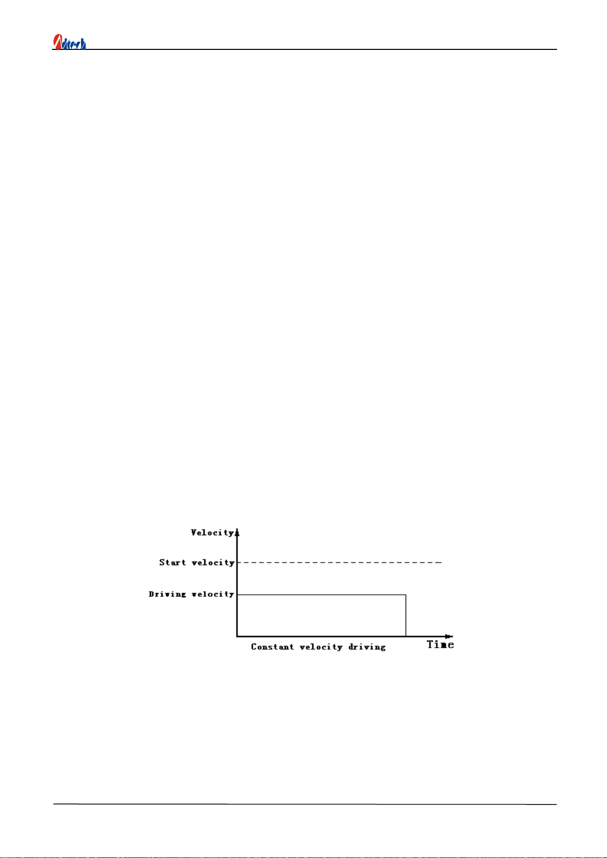
3.1 Constant velocity driving
Constant velocity driving is to output driving pulses in constant speed. If the set driving velocity
is lower than start velocity, there is only constant velocity driving. Only low velocity constant driving
is necessary if you use home searching and coder phase Z signals and stop immediately when signals
are searched.
Configure the following parameters to execute constant velocity driving:
z Range R
z Start velocity SV
z Driving velocity V
21
http://www.adtechcn.com

ADT8948A1 4-axis Servo/Stepping Motion Card
3.2 Linear acceleration/deceleration driving
Linear acceleration/deceleration driving is to accelerate from start velocity to specified driving
velocity linearly.
In quantitative driving, the acceleration counter records the accumulated pulses of acceleration. If
left output pulses are less than acceleration pulses, it will decelerate (automatically). In deceleration, it
will decelerate to start velocity linearly in specified velocity.
Configure the following parameters to execute linear acceleration/deceleration driving:
z Range R
z Acceleration A
Acceleration and deceleration
z Deceleration D Deceleration if they are set separately (if necessary)
z Start velocity SV
z Driving velocity V
0 Triangle prevention in quantitative driving
In quantitative driving of linear acceleration/deceleration, if the output pulses are less than the
required pulses to accelerate to driving velocity, triangle waves as shown in the picture will appear,
and triangle prevention is activated in this case.
The triangle prevention function is to prevent triangle wave if the output pulses are less than
required pulses in linear acceleration/deceleration quantitative driving. In acceleration, if the pulses
consumed by acceleration and deceleration are more than 1/2 of total output pulses, acceleration stops
and keeps in constant velocity field. Therefore, even if output pulses are less than 1/2 of output pulses,
it is in constant velocity field.
22
http://www.adtechcn.com

ADT8948A1 4-axis Servo/Stepping Motion Card
3.3 Asymmetrical linear acceleration/deceleration driving
When an object is moved vertically, it has the load of acceleration of gravity; therefore, you’d
better change the acceleration and deceleration in such asymmetrical linear acceleration/deceleration
quantitative driving whose acceleration and deceleration are different. At this moment, you needn’t to
set manual deceleration point and automatic deceleration is used. Fig. 1 shows the example that
acceleration is lower than deceleration and Fig. 2 shows the example that deceleration is lower than
acceleration.
23
http://www.adtechcn.com
ADT8948A1 4-axis Servo/Stepping Motion Card
Configure the following parameters like common linear acceleration/deceleration driving:
z Range
R
z Acceleration A
z Deceleration D
z Start velocity SV
z Driving velocity V
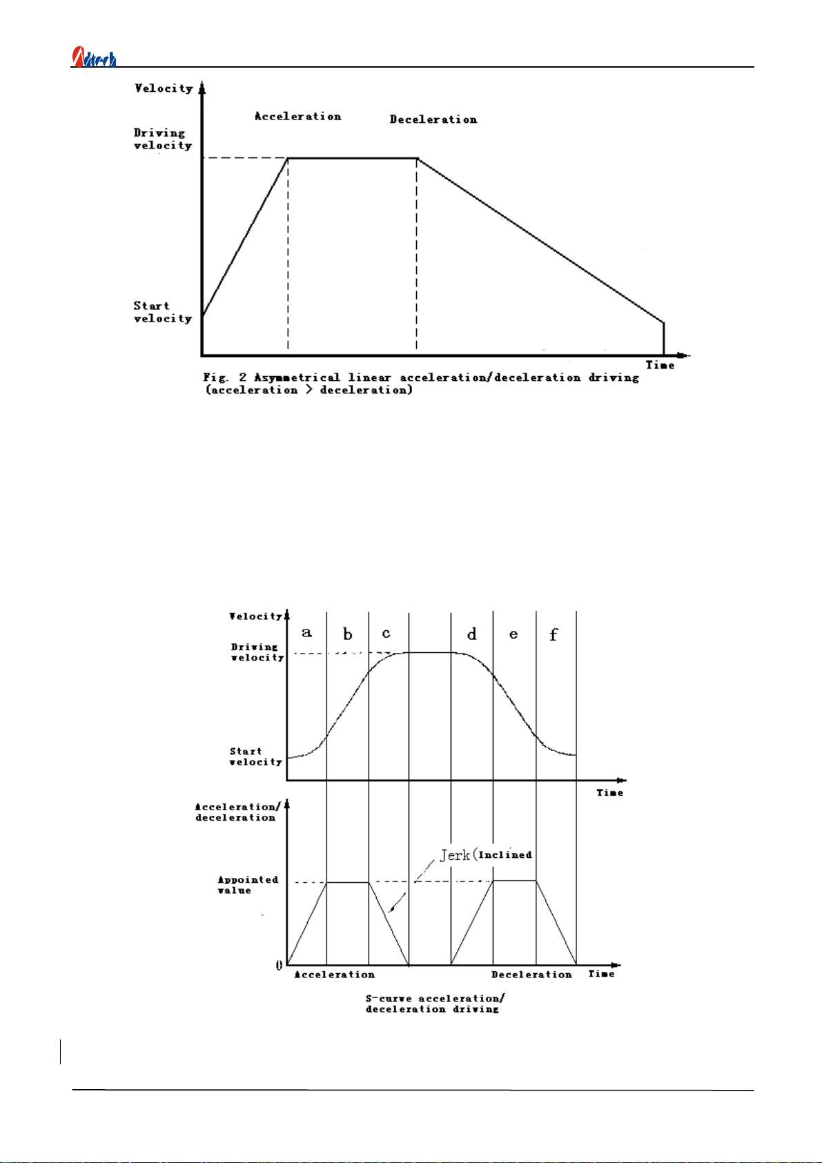
3.4 S-curve acceleration/deceleration driving
When driving velocity accelerates or decelerates, the
acceleration/deceleration can be increased
When the driving accelerates, the acceleration increases from zero linearity to appointed
value (A) in appointed rate (K). Therefore, this velocity curve becomes secondary parabola
24
http://www.adtechcn.com

ADT8948A1 4-axis Servo/Stepping Motion Card
(a-zone). When the acceleration reaches this value (A), it will retain this value. At this moment,
the velocity curve is in linear mode and the velocity is accelerating (b-zone). The acceleration
tends to be 0 if the difference between target velocity (V) and current velocity is less than the
velocity increased in corresponding time. The decreasing rate is same as increasing rate and
decreases in appointed rate (K). At this moment, the velocity curve is in linear mode and the
velocity is accelerating (c-zone). In this manual, the accelerating with partly fixed acceleration is
called as partial S-curve accelerating.
On the other hand, b-zone will disappear if the difference between target velocity (V) and current
velocity is less than the velocity increased in corresponding time before the acceleration reaches
appointed value (A) in a-zone. The accelerating without fixed acceleration is called as complete
S-curve accelerating.
To perform S-curve acceleration/deceleration, you need to set the accelerating mode as
S-curve and then configure the following parameters:
z Range
z Change rate of acceleration/deceleration K
z Acceleration A
z Deceleration D (if necessary)
z Start velocity SV
z Driving velocity V
Precautions of performing S-curve acceleration/deceleration driving:
z Do not change the driving velocity when performing S-curve
acceleration/deceleration quantitative driving.
z
Do not drive are interpolation or continuous interpolation when performing S-curve
acceleration/deceleration.
)
Position management
R
25
http://www.adtechcn.com

ADT8948A1 4-axis Servo/Stepping Motion Card
4.1 Logical position counter and actual position counter
Logical position counter is used to count the positive/negative output pulses of ADT8948A1
card. It counts up 1 after the output of one positive pulse and counts down 1 after the output of
one negative pulse.
Actual position counter counts the input pulses from external coder. You can select the type of
input pulse A/B phase signal or independent 2-pulse up/down counting signals. The counting
direction can be customized.
The data of the two counters can be written or read at any time. The counting range is
-2,147,483,648~+2,147,483,647.
4.2 Compare register and software limit
Each axis has two 32-bit registers (COMP+ COMP-), which can compare size with logical
position counter and actual position counter. You can customize the objects of the two compare
registers as logical position counter or actual position counter. COMP+ register is mainly used to
detect the upper limit of logical/actual position counter and COMP- register is mainly used to
detect the lower limit.
When software limit is valid, deceleration stop is performed if the value of logical/actual
position counter in the driving is bigger than the value of COMP+, and then only negative
driving commands can be executed until the value of logical/actual position counter is smaller
than the value of COMP+. Similarly, deceleration stop is performed if the value of ogical/actual
position counter is smaller than the value of COMP-, and then only positive driving commands
can be executed until the value of logical/actual position counter is bigger than the value of
COMP-.
COMP+ register and COMP- register can be written at any time.
4.3 Variable circle of position counter
The logical position counter and actual position driver are 32-bit up/down cyclic counters.
Therefore, if you count from the 32-bit maximum value FFFFFFFFh to + direction, the last
counting will be 0; count from 0 to – direction, the last counting will be FFFFFFFFh. With
variable circle function, you can customize the maximum value of the cyclic counter. If the
26
http://www.adtechcn.com

ADT8948A1 4-axis Servo/Stepping Motion Card
position is not in linear but rolling motion, it is convenient to control position with this function.
When variable circle function is activated, COMP+ register sets the maximum value of logical
position counter and COMP- register sets the maximum value of actual position counter.
If X-axis is the rotating axis, supposing X-axis rotates one circle every 10,000 circles and
variable corcle function is valid, set 9,999 on COMP+ register; if actual position counter is used
at the same time, set 9,999 on COMP- register.
Then, the counting:
Count up to + direction: … → 9998 → 9999 → 0 → 1 …
Count down to - direction: … → 1 → 0 → 9999 → 9998 …
Then, the counting range is 0-9999 and you needn’t to consider the calculation when the
value is over 10,000.
Note
z You need to activate/deactivate the variable circle function of each axis, but can’t
activate/deactivate logical position counter and actual position counter separately.
z Software limit is invalid if variable circle function is activated.
)
Interpolation
ADT8948A1 card can perform linear interpolation of random 2-3 axes and arc interpolation
of random 2 axes.
In interpolation driving process, the interpolation operation is performed in basic pulse time
series of appointed axis. Before executing interpolation command, you need to set the start
velocity and driving velocity of appointed axis.
Threshold-crossing error in interpolation
In interpolation driving, every driving axis can perform hardware limit and software limit.
The interpolation driving will stop if the limit of any axis changes.
27
http://www.adtechcn.com

ADT8948A1 4-axis Servo/Stepping Motion Card
0
Note
The interpolation will stop if the hardware limit or software limit in any direction (+/-) is
activated in the arc interpolation process. Therefore, you must be careful when perform arc
interpolation and can't leave limit area.
In-position signal of servo motor
The interpolation driving will stop once the INPOS signal of each axis is valid. The INPOS
signals of all axes are in effective electricity level when the interpolation driving is finished.
5.1 2-3 axes linear interpolation
The linear interpolation starts when the end coordinate relative to current position is set. The
coordinate range of linear interpolation is 24-bit with symbols. The interpolation range is from
current position of each axis to -8,388,607~+8,388,607.
As shown in the picture above, the position precision of appointed line is ±0.5LSB in the
whole interpolation range. The above picture also shows the example of pulse output of linear
interpolation driving. In set end-point values, the axis with maximum absolute value is long axis
and this axis always outputs pulses in the interpolation driving process. Other axes are short axes
and they output pulses sometimes according to the result of linear interpolation operation.
5.2 Arc interpolation
Set the center coordinates and end-point coordinates of the arc relative to the start point of
current position, and then perform arc interpolation.
28
http://www.adtechcn.com

ADT8948A1 4-axis Servo/Stepping Motion Card
CW arc interpolation draws arc from current coordinates to end-point coordinates in
clockwise direction around the center coordinates. CCW arc interpolation draws arc around the
center coordinates in counterclockwise direction. It will draw a complete circle if the end point is
(0, 0).
The arithmetic of arc interpolation is shown in the picture below. A plane is defined by
X-axis and Y-axis. Devide it into 8 quadrants (0-7) around center coordinates. At the
interpolation coordinates (X, Y) of quadrant 0, absolute value Y is always smaller than absolute
value X. The axes with smaller absolute values are short axes. Quadrants 1, 2, 5 and 6 are X axes
and quadrants 0, 3, 4 and 7 are Y axes. Short axes always output dricing pulses in these quadrants
and long axes output pulses sometimes according to the result of arc interpolation operation.
The following examples show the output of a complete circle (take pulse output as an example).
29
http://www.adtechcn.com

ADT8948A1 4-axis Servo/Stepping Motion Card
Judgment of end-point
For arc interpolation, set the current coordinates as (0, 0) before starting interpolation driving,
then, determine the radius according to the value of center coordinates and draw a circle. The
error of arc algorithmic is one pulse within the range of interpolation driving. Therefore, the
appointed end-point may be not on the track of the circle. When the arc interpolation enters the
quadrant of end-point, it will stop if the value of end point is same to the value of short axis of
end point.
5.3 Continuous interpolation
For motion card without continuous interpolation function, if you want to continue next
interpolation after the previous interpolation, you have to check whether the previous
interpolation is finished and then output the data of next interpolation. If the upper computer is
too slow, or multi-task OS is run on the upper computer, an intermission, which has a adverse
impact on effect and velocity of interpolation, occurs between interpolations.
ADT8948A1 card is intergrated with continuous interpolation function and thus this problem
is solved. It can output the data of next interpolation before previous interpolation is finished. It
can get excellent effect even if the computer is slow.
In continuous interpolation driving, read the writable state of continuous interpolation and
interpolation driving state first, you can write the command of next interpolation if the
interpolation hasn’t been finished and it is writable. Therefore, in all interpolation nodes, the time
from the beginning to the end of continuous interpolation driving should be more than the time of
setting the data of next interpolation node and sending command.
30
http://www.adtechcn.com

ADT8948A1 4-axis Servo/Stepping Motion Card
Errors in continuous interpolation
In continuous interpolation driving process, if invalid drivings like
threshold-crossing error
occur, it stops immediately at current interpolation node. At stopped interpolation node, the
command is invalid although the data and command of next node still exist. In addition, you need
to check error before sending interpolation command. If you haven’t checked, the data and
command will be invalid when error occurs and driving stops. If it is started from the second
interpolation node at the bottom, you have to check. If any error is found, the circle of continuous
interpolation should be disengaged.
If there is arc interpolation in continuous interpolation, the value of short axis of arc
interpolation end point might deviate one pulse from actual value. To avoid accumulating the
errors of every node, you have to confirm the end point of every arc interpolation first and then
determine the mode of continuous interpolation.
5.4 Interpolation of acceleration/deceleration driving
The interpolation is usually driven in constant velocity. But ADT8948A1 card can perform
interpolation in linear acceleration/deceleration driving or S-curve acceleration/deceleration driving
(for linear interpolation only).
To realize acceleration/deceleration driving in continuous interpolation, you can use deceleration
valid command and deceleration invalid command. In interpolation driving, deceleration valid
command is used to make automatic or manual deceleration valid and deceleration invalid command
is used to make them invalid. To run interpolation driving in acceleration/deceleration separately, you
must select deceleration valid state before driving, otherwise, the deceleration valid command is
invalid when you write it in the driving process.
Acceleration/deceleration driving of linear interpolation
In linear interpolation, linear acceleration/deceleration driving, S-curve acceleration/deceleration driving
and automatic deceleration can be performed.
Acceleration/deceleration driving of arc interpolation
In bit mode arc interpolation, only manual decelerated linear acceleration/deceleration driving
instead of S-curve acceleration/deceleration driving and automatic deceleration can be performed.
Acceleration/deceleration driving of continuous interpolation
In continuous interpolation,
instead of S-curve acceleration/deceleration driving and automatic deceleration can be performed.
only manual decelerated linear acceleration/deceleration driving
In
continuous interpolation, you need to set manual deceleration point first. This manual
deceleration point is set on the final node of deceleration and the value of basic oulse from X axis
is also set. To perform continuous interpolation, deactivate interpolation deceleration first and
then perform interpolation driving. At the final interpolation node to be decelerated, write allow
deceleration command before writing interpolation command. Then, the deceleration is valid
when the driving of final interpolation node starts. Deceleration starts when basic pulses from X
axis of final interpolation node are bigger than the value of manual deceleration point.
For example, in the continuous interpolation from node 1 to node 5, the procedures are as
follows if manual deceleration is performed on final node 5.
Set the acceleration/deceleration mode and
parameters of main axis
↓
31
http://www.adtechcn.com

Write manual deceleration point
↓
Write deceleration invalid command
↓
Interpolation command of node 1
↓
Detect error and wait to write next data
↓
Interpolation command of node 2
↓
Detect error and wait to write next data
↓
Write deceleration valid command
Interpolation command of node 5
ADT8948A1 4-axis Servo/Stepping Motion Card
↓
Set the manual deceleration point according to the value of basic pulses from node 5. For
example, supposing that the deceleration consumes 2,000 pulses and total amount of basic pulses
from node 5 is 5,000, set manual deceleration point as 5,000-2,000=3,000.
The deceleration should be performed within one node from start to end. The total basic pulses
from X axis to Z axis of final interpolation point of decelerated stop should be more than the pulses
consumed by deceleration.
)
Pulse output mode
The driving output pulse has two pulse output modes as shown in the figure below. In
independent 2-pulse mode, PU/CW output driving pulse in positive driving and DR/CCW output
driving pulse in negative driving. In single pulse mode, PU/CW output driving pulse and
DR/CCW output direction signal.
)
Hardware limit signal
Hardware limit signals (LMT+, LMT-) are used to limit the input signals of positive and
32
http://www.adtechcn.com

ADT8948A1 4-axis Servo/Stepping Motion Card
negative direction driving pulses. If the limit signals and their logical level are valid, you can
select decelerated stop or sudden stop with command.
)
Signals corresponding to servo motor
The input signals connected to servo motor drive are INPOS signal and ALARM signal. You
can activate/deactivate each signal and set the logical electricity level.
INPOS signal corresponds to the position end signal of servo motor. If the mode is valid,
when a driving is finished, the waiting INPOS input signal is valid and the driving state is
finished. ALARM input signal receives alarm signal from servo motor drive. It monitors the
ALARM input signal if it is valid. If the signal is valid, the driving will be stopped immediately.
You can read the status of the input signals for servo motor drive with universal I/O function.
Universal output signal can be used to clear counter, reset counter or turn on servo.
)
Position lock
Realize hardware position lock function with the IN signal on each axis. With one lock signal,
the current position (either logical or actual) of all axes can be locked.
The position lock is usefyl in mearsuring system.
)
Automatically back to home
1. Back to hone includes four steps:
(1) Approach stop0 signal in high velocity;
(2) Approach stop1 signal in low velocity;
(3) Approach stop2 signal in low velocity;
(4) Move from home to start point of processing in high velocity.
2. Process analysis
You can select whether perform the above four steps or not, as well as the direction of each step;
you can also use same signal in different steps.
)
External signal driving
External signal driving is the motion controlled by external signals (handwheel or switch). It is
mainly used in the manual debugging of machines and provides a lot of convenience in teaching
system.
To simplify the wiring, the motion card short connects the positive driving signals of the four
axes and also short connects the negative driving signals of the four axes; therefore, only one signal
cable of the coder is connected to the external interface of external singals.
)
Stepping interpolation
Stepping interpolation is to perform interpolation in single step. When one step is finished, the
next interpolation motion will be performed while waiting for the command or signal of next
interpolation.
Stepping interpolation is mainly used in multi-axis manual debugging.
33
http://www.adtechcn.com

ADT8948A1 4-axis Servo/Stepping Motion Card
Chapter VI Basic Library Functions List of ADT-8948A1
Function
catalog
Function name Description Page
adt8948_initial Initial card 33
Basic
parameters
adt8948_end
set_stop0_mode
set_stop1_mode
set_stop2_mode
set_actualcount_mode
set_pulse_mode
set_limit_mode
set_softlimit_mode1
set_softlimit_mode2
set_softlimit_mode3
disable_soft_limit
End card 33
Home signal mode 33
Home signal mode 34
Home signal mode 34
Actula position counter mode 34
Pulse mode 35
Limit mode 35
Soft limit mode 36
Soft limit mode 36
Soft limit mode 36
Soft limit mode enabled 37
enable_soft_limit Disable soft limit mode 37
Driving status
checking
set_inpos_mode
set_alarm_mode
set_ad_mode
set_dec1_mode
set_dec2_mode
set_circle_mode
set_input_fiilter
set_filer_time
set_lock_position
Set position lock mode 39
Servo in-position mode 37
Servo alarm mode 37
Acceleration/deceleration mode 38
Asymmetric
acceleration/deceleration setting
Deceleration mode 38
Variable circle mode 38
Signal filtering 39
Signal filtering time 39
get_status Get axis driving status 40
get_stopdata Get error stop data 40
get_inp_status Get interpolation driving status 41
38
34
http://www.adtechcn.com

ADT8948A1 4-axis Servo/Stepping Motion Card
Driving
parameters
setting
get_inp_status2
get_lock_status
get_home_status
get_home_error
Get lock status 41
Get back-to-home error 42
Continuous interpolation writing
status
Get back-to-home status 42
41
set_range Set range 42
set_acac Set acceleration changing rate 43
set_acc Set acceleration 43
set_dec Set deceleration 44
set_startv Set start speed 44
set_speed Set driving speed 44
set_command_pos Set logical position counter 45
set_actual_pos Set actual position counter 45
set_comp1 Set register 45
set_comp2 Set register 46
Driving
parameters
checking
Version
number
set_soft_limit
Set software limit value 46
set_dec_pos Set deceleration position 46
set_vector_speed Set speed mode 46
set_home_mode
set_symmetry_speed
set_unsymmetry_speed
Set back-to-home mode 47
Set symmetric
acceleration/deceleration
Set asymmetric
acceleration/deceleration
get_command_pos Get logical position 48
get_actual_pos Get actual position 48
get_speed Get driving speed 49
get_ad Get acceleration 49
get_lock_position
Get lock position 49
get_lib_vision Get library functions version 49
47
48
Basic driving
pmove Single axis quantitative driving 49
continue_move Continuous driving 50
35
http://www.adtechcn.com

ADT8948A1 4-axis Servo/Stepping Motion Card
dec_stop Decelerated stop 50
sudden_stop Sudden stop 50
stop
stop
_axis
_all
Stop axis 50
Stop all axes 51
inp_move2
inp
_cw_arc
inp_ccw_arc
Two axes inperpolation 51
Clockwise arc interpolation 51
Counterclockwise arc
interpolation
inp_move3 Three axes interpolation 52
inp_dec_enable
inp_dec_disable
manual_pmove
manual_continue
manual_disable
inp_step_command2
inp_step_command3
inp_step_move
inp_step_signal2
inp_step_signal3
inp_step_stop
Interpolation deceleration
enabled
Interpolation deceleration
disabled
Quantitative driving of external
signals
Continuous driving of external
signals
Disable external signals driving 53
Two axes command stepping
interpolation
Three axes command stepping
interpolation
Stepping interpolation driving
command
Two axes signal stepping
interpolation
Three axes signal stepping
interpolation
Stepping interpolation stop
command
51
52
52
53
53
53
54
54
54
54
55
Synchronized
function
setting
home
clear_home_error
set_in_move1
set_in_move2
set_in_move3
Back to home 55
Clear back-to-home error
Single axis following signal
moving
Two axes following signal
moving
Three axes following signal
moving
36
55
56
56
56
http://www.adtechcn.com

ADT8948A1 4-axis Servo/Stepping Motion Card
Composite
driving
set_in_stop1
set_in_stop2
set_in_stop3
set_comp_pmove1
set_comp_pmove2
set_comp_pmove3
set_comp_stop1
set_comp_stop2
set_comp_stop3
Single axis following signal stop 57
Two axes following signal stop 57
Three axes following signal stop 57
symmetry_relative_move
symmetry_absolute_move
unsymmetry_relative_move
unsymmetry_absolute_move
symmetry_relative_line2
symmetry_absolute_line2
unsymmetry_relative_line2
unsymmetry_absolute_line2
symmetry_relative_line3
symmetry_absolute_line3
unsymmetry_relative_line3
unsymmetry_absolute_line3
symmetry_relative_arc
symmetry_absolute_arc
Position comparison single axis
moving
Position comparison two axes
moving
Position comparison three axes
moving
Position comparison single axis
stop
Position comparison two axes
stop
Position comparison three axes
stop
Single axis symmetric relative
moving
Single axis symmetric absolute
moving
Single axis asymmetric relative
moving
Single axis asymmetric absolute
moving
Two axes symmetric linear
interpolation relative moving
Two axes symmetric linear
interpolation absolute moving
Two axes asymmetric linear
interpolation relative moving
Two axes asymmetric linear
interpolation absolute moving
Three axes symmetric linear
interpolation relative moving
Three axes symmetric linear
interpolation absolute moving
Three axes asymmetric linear
interpolation relative moving
Three axes asymmetric linear
interpolation absolute moving
Two axes symmetric arc
interpolation relative moving
Two axes symmetric arc
interpolation absolute moving
58
58
58
59
59
59
60
60
61
61
61
62
62
62
63
63
64
64
65
65
37
http://www.adtechcn.com

ADT8948A1 4-axis Servo/Stepping Motion Card
Switch signals
unsymmetry_relative_arc
unsymmetry_absolute_arc
read_bit Read single input bit 66
write_bit Output single bit 67
get_out Get output status 67
Two axes asymmetric arc
interpolation relative moving
Two axes asymmetric arc
interpolation absolute moving
66
66
38
http://www.adtechcn.com

ADT8948A1 4-axis Servo/Stepping Motion Card
Chapter VII Details of Basic Library Functions of ADT8948A1
)
Basic parameters settings
)
Initialize ADT-8948A1 card
int adt8948_initial(void);
Function
Initialize motion card
Return value
Return value is the quantity of ADT-8948 cards in the system. Value 3 indiates that
three cards have been installed and available card numbers are 0, 1 and 2;
Value 0 indicates that no ADT-8948A1 card has been installed;
Value -1 indicates that the drivers of ADT-8948A1 card haven’t been installed
Relative default status after initialization:
Pulse output mode: pulse + direction
Feedback input is A/B phase coding pulse input with 4 times frequency doubling
STOP0, STOP1 and STOP2 are invalid
Limit signals LMT+ and LMT- are low electricity level valid, sudden stop
Software limit is invalid
Servo nINPOS signal is invalid
Servo nALARM signal is invalid
Available acceleration/deceleration modes are linear, symmetric and automatic.
The variable circle function of counter is invalid
Input filtering is invalid
Note
Initialization function is the premise to invoke other functions. You need to invoke this
function first to confirm available cards and initialize certain parameters.
)
Release ADT-8948A1 card
int adt8948_end(void);
Function
Release the resources of motion card
Return value
)
Set the mode of stop0 signal
0:correct 1:wrong
int set_stop0_mode(int cardno, int axis, int value,int logic);
Function
Setup of STOP0 signal
valid
/in
valid
and logic electric level
Parameter
cardno card number
axis axis number(1-4)
value 0:invalid 1:valid
logic 0:low electric stop 1:high electric stop
Return value 0:correct 1:wrong
Default modes
Signal is
invalid,low electric stop
Notice
The way to stop rests on that it is A/D drive or uniform acceleration drive. For former
39
http://www.adtechcn.com

ADT8948A1 4-axis Servo/Stepping Motion Card
it is A/D stop while for latter instant stop. STOP1 and STOP2 are just the same
)
Set the mode of stop1 signal
int set_stop1_mode(int cardno, int axis, int value,int logic);
Function
Setup of STOP1 signal
valid
/in
valid
and logic electric level
Parameter
cardno card number
axis axis number(1-4)
value 0:invalid 1:valid
logic 0:low electric stop 1:high electric stop
Return value
Default modes
0:correct 1:wrong
Signalinvalid,low electric stop
)
Set the mode of stop2 signal
int set_stop2_mode(int cardno, int axis, int value,int logic);
Function
Setup of STOP2 signal
valid
/in
valid
and logic electric level
Parameter
Parameter
cardno card number
axis axis number(1-4)
value 0:invalid 1:valid
logic 0:low electric stop 1:high electric stop
Return value
Default modes
0:correct 1:wrong
Signalinvalid,low electric stop
Notice
STOP2 signal can clear actual position counter when it is valid. Due to the delay of servo
system or mechanical system, error may occur in home position if you clear the actual
position counter with software after driving. With this function, you can get higher
precision.
)
Set the working mode of actual position counter (coder input)
int set_actualcount_mode(int cardno, int axis, int value,int dir,int freq);
Function
Set working mode of actual position counte
Parameter
cardno card number
axis axis number(1-4)
value
Pulse input mode
0:A/B pulse input
1:Up/Down (PPIN/PMIN) pulse input
dir Counting direction
A leads B or PPIN pulse input up count
0:
40
http://www.adtechcn.com

ADT8948A1 4-axis Servo/Stepping Motion Card
B leads A or PMIN pulse input down count
1:
B leads A or PMIN pulse input up count
A leads B or PPIN pulse input down count
freq
Frequency multiplication of A/B pulse input, Invalid for Up/Down pulse input
0: 4× 1: 2× 2: 1×
Return value
Default modes
0:correct 1:wrong
A/B pulse input,direction: 0,Frequency multiplication: 4×
Most position feedback devices use coder or grating scale, so you need to select A/B phase
pulse input mode. The precision of this mode can be improved with frequency doubling
technology. You can select 4 times or 2 times, or disable frequency doubling. For 4 times
frequency doubling, if a coder of 1000 pulse per circle is used, the counter value will increase
by 4000 when it rotates one circle clockwise, i.e. the precision is increased by 4 times
)
Set working mode of output pulse
int set_pulse_mode(int cardno, int axis, int value,int logic,int dir_logic);
Function
Set working mode of output pulse
Parameter
cardno card number
axis axis number(1-4)
value 0:Pulse + Pulse 1:Pulse + Direction
logic 0:Positive logical pulse 1:Negative logical pulse
dir-logic 0: Positive direction pulse output
1:Negative direction pulse output
41
http://www.adtechcn.com

ADT8948A1 4-axis Servo/Stepping Motion Card
Return value
Default mode
output signal
)
Set the working mode of limit signal
Pulse + direction; positive logical pulse; Positive logic of direction
0:correct 1:wrong
int set_limit_mode(int cardno, int axis, int value, int logic);
Function
Set the mode of positive/negative limit input signal nLMT
Parameter
cardno card number
axis axis number(1-4)
value 0:sudden stop 1:decelerated stop0:sudden stop 1:decelerated
stop
logic 0:low electric valid 1:high electric valid
Return value
Default modes
0:correct 1:wrong
sudden stop,low electric valid
Notice
The limit signal can’t be valid or invalid.
)
Setting of COMP+ register as software limit
int set_softlimit_mode1(int cardno, int axis, int value);
Function
Set COMP + register as software limit
Parameter
cardno card number
axis axis number(1-4)
value 0:invalid 1:valid
Return value
Default modes
0:correct 1:wrong
invalid
Notice
Software limit is always decelerated stop and the counting value may exceed the
setting value. It is necessary to consider this point while setting range
)
Setting of COMP- register as software limit
int set_softlimit_mode2(int cardno, int axis, int value);
Function
Set COMP - register as software limit
Parameter
cardno card number
axis axis number(1-4)
value 0:invalid 1:valid
Return value
0:correct 1:wrong
42
http://www.adtechcn.com

ADT8948A1 4-axis Servo/Stepping Motion Card
Default modes
invalid
Notice
The same as above
)
Comparison objects setting of COMP+/- registers
int set_softlimit_mode3(int cardno, int axis, int value);
Function
set
COMP+/- registers
as the compare objects of software limit
Parameter
cardno card number
axis axis number(1-4)
value 0:Logical position counter 1:Actual position counter
Return value
Default modes
0:correct 1:wrong
Logical position counter
This function is the comparison object of setting software limit.
)
Set software limit invalid
int disable_soft_limit(int cardno, int axis);
Function
set
software limit
function invalid
Parameter
cardno card number
axis axis number
Return value
(1-4)
0:correct 1:wrong
Notice
This function is encapsulated with COMP+ and COMP- setting functions.
)
Set software limit valid
int enable_soft_limit(int cardno, int axis, int value);
Function
set
software limit
function valid
Parameter
cardno card number
axis axis number
(1-4)
value compare objects (0: logical position counter;1:Actual position counter)
Return value
0:correct 1:wrong
Notice
This function is encapsulated with COMP+, COMP- and COMP+/- setting functions
)
Setting of servo in-position signal nINPOS
int set_inpos_mode(int cardno, int axis, int value, int logic);
Function
Setting of servo in-position signal nINPOS
Parameter
cardno card number
axis axis number(1-4)
value 0:invalid 1:valid
43
http://www.adtechcn.com

logic 0:low electricvalid 1:high electricvalid
Return value
Default modes
0:correct 1:wrong
invalid,low electricvalid
Notice
Do not select valid if nINPOS isn’t connected to servo or stepping motor is used.
)
Setting of servo alarm signal nALARM
int set_alarm_mode(int cardno, int axis, int value,int logic);
Function
Set the working mode of servo alarm signal nALARM
Parameter
cardno card number
axis axis number(1-4)
value 0:invalid 1:valid
logic 0:low electric valid 1:high electric valid
Return value
Default modes
0:correct 1:wrong
invalid,low electric valid
Notice
Do not select valid if nALARM isn’t connected to servo or stepping motor is used
ADT8948A1 4-axis Servo/Stepping Motion Card
)
Acceleration/deceleration setting
int set_ad_mode(int cardno, int axis, int value);
Function
Select linear or S-curve acceleration/deceleration
Parameter
cardno card number
axis axis number(1-4)
value 0:linear A/D 1:S-curve A/D
Return value
Default modes
)
Asymmetric ladder acceleration/deceleration setting
0:correct 1:wrong
linear A/D
int set_dec1_mode(int cardno, int axis, int value);
Function
Select symmetric or asymmetric acceleration/deceleration
Parameter
cardno card number
axis axis number(1-4)
value deceleration mode
(0: symmetric deceleration, 1: asymmetric deceleration)
Return value
Default modes
0:correct 1:wrong
symmetric acceleration/deceleration
)
Deceleration mode setting of acceleration/deceleration quantitative driving
int set_dec2_mode(int cardno, int axis, int value);
Function
Set deceleration mode
44
http://www.adtechcn.com

Parameter
cardno card number
axis axis number(1-4)
value 0:automatic deceleration 1: manual deceleration
Return value
Default modes
0:correct 1:wrong
Automatic deceleration
Notice
Automatic deceleration is used in most cases. To use manual deceleration, it is
necessary to set deceleration point
)
Setting of variable circle function of the counter
int set_circle_mode(int cardno, int axis, int value);
Function
Set the variable circle mode of counter
Parameter
cardno card number
axis axis number(1-4)
value 0:invalid 1:valid
Return value
Default modes
0:correct 1:wrong
invalid
ADT8948A1 4-axis Servo/Stepping Motion Card
)
Input signal filtering function setting
int set_input_filter(int cardno,int axis,int number,int value);
Function
Set the filtering function of input signal
Parameter
cardno card number
axis axis number
number Input types
1:LMT+、LMT-、STOP0、STOP1
2:STOP2
3:nINPOS、nALARM
4:nIN
Set the filtering state of the four types input signals above
value 0: Filtering invalid 1: Filtering valid
Return value
Default modes
)
Constant setting of filtering time of input signals
0:correct 1:wrong
invalid
int set_filter_time(int cardno,int axis,int value);
Function
Set the filtering time constant of input signals
Parameter
cardno card number
axis axis number
value Range: 1-8, and the meanings are as follow:
45
http://www.adtechcn.com

ADT8948A1 4-axis Servo/Stepping Motion Card
Return value
)
Set the working mode of position lock
0:correct 1:wrong
int set_lock_position(int cardno, int axis,int regi,int logical);
Function
Set the working mode of position lock
Parameter
cardno card number
axis axis number
regi Counter type (0:logical position counter;1:Actual position counter)
logical Electricity level logic of lock signals (0: low level lock; 1: high level
lock)
Return value
0:correct 1:wrong
)
Driving status checking
)
Get the driving status of single axis
int get_status(int cardno,int axis,int *value)
Function
Get the driving status of single axis
Parameter
cardno card number
axis axis number(1-4)
value Index of driving status; the meanings are:
0: Driving stopped
Non-0: the value is in 2 bytes and their meanings are:
D0 is the lowest position and D15 is the highest position
D0: indicate the size comparison of logical/actual position counter and COMP+ register
1: logical/actual position counter >=COMP+ register
0: logical/actual position counter <COMP+ register
D1: indicate the size comparison of logical/actual position counter and COMP- register
1: logical/actual position counter >=COMP- register
0: logical/actual position counter <COMP- register
D2: In acceleration/deceleration driving, it is 1 in acceleration
D3: In acceleration/deceleration driving, it is 1 in constant speed
D4: In acceleration/deceleration driving, it is 1 in deceleration
D5: In S-curve acceleration/deceleration driving, it is 1 when acceleration/deceleration is
increased
46
http://www.adtechcn.com

D6: In S-curve acceleration/deceleration driving, it is 1 when acceleration/deceleration is
constant
D7: In S-curve acceleration/deceleration driving, it is 1 when acceleration/deceleration is
decreased
D8-D15: Reserved
Return value
0:correct 1:wrong
Notice
If single axis driving command is executed, you can send next driving instruction to the axis
when the driving of corresponding axis is stopped. Otherwise, previous driving instruction
stops immediately and next instruction is executed.
)
Get the error stop data of axes
int get_stopdata(int cardno,int axis,int *value)
Function
Get the error stop data of axes
Parameter
cardno card number
axis axis number(1-4)
value Index of error status
0: No error
Non-0: the value is in 2 bytes and their meanings are :
D0 is the lowest position and D15 is the highest position
D0: Stopped by STOP0
D1: Stopped by STOP1
D2: Stopped by STOP2
D3: Stopped by positive limit LMT+
D4: Stopped by negative limit LMTD5: Stopped by servo alarm
D6: COMP+ register limit driving stopped
D7: COMP- register limit driving stopped
D8-D15: Reserved
Return value
0:correct 1:wrong
ADT8948A1 4-axis Servo/Stepping Motion Card
)
Get the driving status of interpolation
int get_inp_status(int
cardno
,int *value)
Function
Get the driving status of interpolation
Parameter
cardno card number
value Index of interpolation status
0: Interpolation stopped 1: Interpolating
Return value
0:correct 1:wrong
Notice
If interpolation driving command is executed, you can send next driving instruction to the
axis when the interpolation driving of corresponding axis is stopped. Otherwise, previous
47
http://www.adtechcn.com

driving instruction stops immediately and next instruction is executed.
)
Get the writable status of continuous interpolation
int get_inp_status2(int
cardno
,int *value)
Function
Get the writable status of continuous interpolation
Parameter
cardno card number
value Index of writing status
0: Unwritable 1: Writable
Return value
0:correct 1:wrong
Notice
If the driving is stopped, the status is 0. Threrfore, it is necessary to check whether error
occurs in continuous interpolation process.
)
Get lock status
int get_lock_status(int cardno, int axis, int *status)
Function
Get the status of position lock
Parameter
cardno card number
axis axis number
(1-4)
status Lock status (0: unlocked, 1: locked)
Return value
)
Get back-to-home status
0:correct 1:wrong
int get_home_status(int cardno, int axis, int *status, int *err);
Function
Get back-to-home status
Parameter
cardno card number
axis axis number
(1-4)
status Whether driving is stopped (0:driving stopped, 1: moving)
err Whether error occurs (0:correct,1:wrong)
Return value
0:correct 1:wrong
ADT8948A1 4-axis Servo/Stepping Motion Card
)
Get back-to-home error
int get_home_error(int cardno, int axis ,int *err);
Function
Get back-to-home error information
Parameter
cardno card number
axis axis number
(1-4)
err Error marker
0:correct >0:wrong
The meanings of first 7 digits of err:
D0: comp+ limit
D1: comp- limit
D2: LMT+ limit
48
http://www.adtechcn.com

ADT8948A1 4-axis Servo/Stepping Motion Card
D3: LMT- limit
D4: Servo alarm
D5: Emergency stop
D6: Z phase signal arrives in advance
Return value
)
Moving parameter settings
The values of the following parameters are not fixed when the motion card is initialized.
0:correct 1:wrong
You need to set before using
)
Range setting
int set_range(int cardno,int axis,long value);
Function
set range
Parameter
cardno card number
axis axis number
(1-4)
value range(8000000-16000)
Return value
0:correct 1:wrong
Notice
Range is the rate parameter that determines the speed, acceleration/deceleration and
change rate of acceleration/deceleration. If the range is R, the formula to calculate M is:
M = 8000000/R.
The effective range of driving speed, inialization speed and acceleration/deceleration is
1~8000. If required actual speed or acceleration/deceleration is higher than 8000, you
need to set the range and adjust the magnification. If magnification is increased, the
actual speed and acceleration/deceleration can be increased in same scale, but the
resolution of speed and acceleration/deceleration becomes rough. Therefore, it is
recommended that you set minimum value for magnification and maximum value for
range within stated range of actual speed.
In engineering practice, the setting of reasonable range is the premise to get ideal actual
speed curve. To calculate the range:
Step 1: Calculate the magnification (M) according to estimated maximum actual speed
(Vmax) M=Vmax/8000 (8000 is the maximum speed);
Step 2: Calculate range (R) according to magnification: R = 8000000/M.
For example: if required maximum speed is 40KPPS, then, M = 40*1000/8000 = 5 and
R = 8000000/5 = 1600000.
The range of R is 8000000-16000 and corresponding rate is 1-500.
You’d better set the range in the process of system initialization. Do not change the range
in the moving process; otherwise, the speed may jump.
In a word, actual speed = set value of speed * magnification.
)
Set the change rate of acceleration/deceleration
int set_acac(int cardno,int axis,long value);
Function
Set the change rate of acceleration/deceleration
Parameter
49
http://www.adtechcn.com

ADT8948A1 4-axis Servo/Stepping Motion Card
cardno card number
axis axis number
(1-4)
value range(1-65535)
Return value
Notice
0:correct 1:wrong
The change rate of acceleration/deceleration is the parameter that determines the
change rate of acceleration and deceleration of S-curve acceleration/deceleration in unit time. If
the value of acceleration/deceleration change rate is K, the actual value V (PPS/SEC2) of
acceleration/deceleration change rate is V = (62500000/K)*M = (62500000/K)*(8000000/R).
The range of acceleration/deceleration change rate is 1~65,535.
If the setting is as follow:
set_range(0,1,800000); the range is 800000 and magnification M=8000000/800000=10
set_acac(0,1,100); acceleration/deceleration change rate is 100;
Then, the actual change rate of acceleration/deceleration is (62500000/100)*10=6250000
PPS/SEC2
)
Acceleration setting
int set_acc(int cardno,int axis,l on g val ue);
Function
Set the value of acceleration
Parameter
cardno card number
axis axis number
(1-4)
value range(1-8000)
Return value
Notice
0:correct 1:wrong
This is the acceleration and deceleration parameter in linear acceleration/deceleration
driving. In S-curve acceleration/deceleration driving, the acceleration and deceleration increase
linearly from 0 to set acceleration value.
The set acceleration value is A and the actual acceleration is:
Actual acceleration (PPS/SEC) = A*125*M = A*125*(8000000/R)
The range of acceleration value is 1~8,000.
If the setting is as follow:
set_range(0,1,80000); the range is 800000 and magnification M=8000000/800000=10
set_acc(0,1,100);
The acceleration is:
100*125* (8000000/80000) =1250000 PPS/SEC
)
Deceleration setting
int set_dec(int cardno,int axi s, l ong value);
Function
Set the value of deceleration
Parameter
cardno card number
axis axis number
(1-4)
value D-value(1-8000)
50
http://www.adtechcn.com

ADT8948A1 4-axis Servo/Stepping Motion Card
Return value
Notice
0:correct 1:wrong
It is the deceleration parameter in linear acceleration/deceleration driving in
acceleration/deceleration fixed mode. In S-curve acceleration/deceleration driving, the
deceleration increases linearly from 0 to set deceleration value.
The deceleration value is D and the actual deceleration is:
Actual deceleration (PPS/SEC) = D*125*M=D*125*(8000000/R)
The range of deceleration value D is 1~8,000.
If the setting is as follow:
set_range(0,1,80000); the range is 800000 and magnification M=8000000/800000=10
set_dec(0,1,100);
The deceleration is:
100*125* (8000000/80000) =1250000 PPS/SEC
)
Start velocity setting
int set_startv(int cardno,int axis,long value);
Function
Set the value of start velocity
Parameter
cardno card number
axis axis number
(1-4)
value range(1-8000)
Return value
0:correct 1:wrong
Notice
Start velocity is the velocity when the driving starts. The start velocity value is SV and
the actual value of start velocity is: actual value of start velocity
(PPS) = SV*M =
SV*(8000000/R)
If the value of start velocity is higher than that of driving speed, the drving will be
performed in driving speed constantly even if the acceleration/deceleration has been set.
)
Driving speed setting
int set_speed(int cardno,int axis,long value);
Function
Set the value of driving speed
Parameter
cardno card number
(1-4)
axis axis number
value range(1-8000)
Return value
0:correct 1:wrong
Notice
Driving speed is the speed that reaches constant speed area in the moving process.
The driving speed should be no lower than start velocity in principle. The driving
speed is V and the actual value of driving speed is: actual value of driving speed (
= V*M = V*(8000000/R).In ladder acceleration/deceleration or constant speed moving
process, you can change the driving speed in real time. You can’t change the driving
51
http://www.adtechcn.com
PPS)

speed in the quantitative pulse driving process of S-curve acceleration/deceleration.
Besides, if the speed is changed in acceleration area or deceleration area in the
continuous driving process of S-curve acceleration/deceleration, you can’t run correct
S-curve. Please change the speed in constant speed area.
In the quantitative pulse driving of linear acceleration/deceleration, if the driving speed
si changed frequently, the dragging driving in start velocity will probably occur in the
deceleration at the end of output pulse
)
Logical position counter setting
int set_command_pos(int cardno,int axis,long value);
Function
Set the value of logical position counter
Parameter
cardno card number
axis axis number
(1-4)
value range value(-2147483648~+2147483647)
Return value
Notice
0:correct 1:wrong
You can access the logical position counter in real time
ADT8948A1 4-axis Servo/Stepping Motion Card
)
Actual position counter setting
int set_actual_pos(int cardno,int axis,long value);
Function
Set the value of actual position counter
Parameter
cardno card number
axis axis number
(1-4)
value range value(-2147483648~+2147483647)
Return value
Notice
0:correct 1:wrong
You can access the actual position counter in real time
)
COMP+ register setting
int set_comp1(int cardno,int axis,long value);
Function
Set the value of COMP+ register
Parameter
cardno card number
axis axis number
(1-4)
value range value(-2147483648~+2147483647)
Return value
Notice
0:correct 1:wrong
You can access the COMP+ register in real time
)
COMP- register setting
int set_comp2(int cardno,int axis,long value);
Function
Set the value of COMP- register
52
http://www.adtechcn.com

ADT8948A1 4-axis Servo/Stepping Motion Card
Parameter
cardno card number
axis axis number
(1-4)
value range value(-2147483648~+2147483647)
Return value
Notice
0:correct 1:wrong
You can access the COMP- register in real time
)
Software limit setting
int set_soft_limit (int cardno,int axis,long value1, long value2);
Function
Set the value of software limit
Parameter
cardno card number
axis axis number
(1-4)
value1 positive limit
value2 negative limit
Return value
Notice
This function is encapsulated by COMP+ and COMP-.
0:correct 1:wrong
)
Manual deceleration point setting
Set the value of manual deceleration point
int set_dec_pos(int cardno,int axis,long value);
Function
Set the value of COMP+ register
Parameter
cardno card number
axis axis number
(1-4)
value range value(0~268435455)
Return value
0:correct 1:wrong
Notice
If manual deceleration mode is used, you need to set manual deceleration point first.Manual
deceleration point = output pulses – pulses consumed by deceleration
)
Set linear speed mode
int set_vector_speed(int cardno, int mode);
Function
Linear speed mode setting
Parameter
cardno card number
mode Speed mode
(0: do not use constant linear speed; 1: use constant linear speed)
Return value
0:correct 1:wrong
Notice
Linear speed indicates vector speed. Constant linear speed can guarantee the constant
combination speed in interpolation
)
Set back-to-home mode
53
http://www.adtechcn.com

ADT8948A1 4-axis Servo/Stepping Motion Card
int set_home_mode(int cardno, int axis,long speed,int logical0, int logical1, int
logical2,int offset,int dir0, int dir1, int dir2,int offsetdir,int
clear,long pulse);
Function
Set back-to-home mode of appointed axis
Parameter
cardno card number
axis axis number
(1-4)
speed Low speed (this value should be lower than start velocity of high speed)
logical0 stop0 electricity level logic
(0:low electric stop, 1:high electric stop,-1:invalid)
logical1 stop1 electricity level logic
(0:low electric stop, 1:high electric stop,-1:invalid)
logical2 stop2 electricity level logic
(0:low electric stop, 1:high electric stop,-1:invalid)
offset Offset symbol (0: do not offset from home, 1: offset from home)
dir0 Direction approaching stop0 (0: positive, 1: negative)
dir1 Direction approaching stop1 (0: positive, 1: negative)
dir2 Direction approaching stop2 (0: positive, 1: negative)
offsetdir Offset direction (0: positive, 1: negative)
clear Clear counter? (0: Yes, 1: No)
pulse Offset pulses
Return value
0:correct 1:wrong
)
Set symmetric acceleration/deceleration
int set_symmetry_speed(int cardno,int axis,long lspd,long hspd,double tacc,long
vacc,int mode);
Function
Set the value of symmetric acceleration/deceleration
Parameter
cardno card number
(1-4)
axis axis number
lspd Start speed
hspd Driving speed
tacc Acceleration time
vacc Acceleration change rate
mode Acceleration mode (0:
Return value
0:correct 1:wrong
trapezoid 1: S-curve)
Notice
This function is composed of the function that sets acceleration/deceleration mode and the
functions that set start velocity, driving speed, acceleration and change rate of
acceleration/deceleration.
)
Set asymmetric acceleration/deceleration
int set_unsymmetry_speed(int cardno,int axis,long lspd,long hspd,double tacc,double
tdec,long vacc,int mode);
Function
Set the value of asymmetric acceleration/deceleration
Parameter
54
http://www.adtechcn.com

cardno card number
axis axis number
(1-4)
lspd start speed
hspd driving speed
tacc acceleration time
tdec deceleration time
vacc acceleration change rate
mode acceleration mode (0: trapezoid 1:S-curve)
Return value
0:correct 1:wrong
Notice
This function is composed of the function that sets acceleration/deceleration mode and the
functions that set start velocity, driving speed, acceleration, deceleration and change rate
of acceleration/deceleration.
)
Moving parameter checking
The following functions can be invoked at any moment.
)
Get the logical position of axes
int get_command_pos(int cardno,int axis,long *pos);
Function
Get the logical position of axes
Parameter
cardno card number
axis axis number
(1-4)
pos Index of logical position value
Return value
0:correct 1:wrong
Notice
You can use this function to get the logical position of axes and it can represent the current
position of axes if the motor is not out of step
ADT8948A1 4-axis Servo/Stepping Motion Card
)
Get the actual position of axes (i.e. coder feedback value)
int get_actual_pos(int cardno,int axis,long *pos);
Function
Get the actual position of axis
Parameter
cardno card number
axis axis number
(1-4)
pos Index of actual position value
Return value
0:correct 1:wrong
Notice
You can use this function to get the actual position of axes and you can get the current
position of axes even if the motor is out of step.
)
Get the current driving speed of axes
int get_speed(int cardno,int axis,long *speed);
Function
Get the current driving speed of axes
Parameter
cardno card number
55
http://www.adtechcn.com

ADT8948A1 4-axis Servo/Stepping Motion Card
axis axis number
(1-4)
speed Index of current driving speed
Return value
Notice
)
Value of actual speed = Getting speed*M = Getting speed*(8000000/R)
Get the current acceleration of axes
int get_ad(int cardno,int axis,long *ad);
0:correct 1:wrong
Function
Get the current acceleration of axes
Parameter
cardno card number
axis axis number
(1-4)
ad Index of current acceleration
Return value
)
Get lock position
0:correct 1:wrong
int get_lock_position( in t card n o, in t axi s, l on g *p os );
Function
Get the latest lock position
Parameter
cardno card number
axis axis number
(1-4)
pos Locked position
Return value
0:correct 1:wrong
)
Library function version checking
)
Get the version of library fu nction
int get_lib_vision(int *ver);
Function
Get the version number of library function
Parameter
ver Version number index (ver is a 4-digit integer with the first two digits are
master version number and last two sigits are secondary version number)
Return value
)
Basic driving
)
Quantitative driving
0:correct 1:wrong
int pmove(int cardno,int axis,long pulse);
Function
Single axis quantitative driving
Parameter
cardno card number
axis axis number
(1-4)
pulse output pulses >0: Positive <0: Negative
range(-268435455~+268435455)
Return value
0:correct 1:wrong
56
http://www.adtechcn.com

ADT8948A1 4-axis Servo/Stepping Motion Card
Notice
You need to set valid speed parameter before writing driving command.
)
Continuous driving
int continue_move(int cardno,int axis,int dir);
Function
Single axis continuous driving
Parameter
cardno card number
axis axis number
(1-4)
dir Driving direction 0: Positive 1: Negative
Return value
Notice
0:correct 1:wrong
You need to set valid speed parameter before writing driving command.
)
Driving
int dec_stop(int cardno,int axis);
decelerated stop
Function
Stop current driving process in deceleration
Parameter
cardno card number
axis axis number
Return value
Notice
(1-4)
0:correct 1:wrong
This command is decelerated stop in acceleration/deceleration driving, process and
sudden stop in constant speed driving process.
)
Driving
sudden stop
int sudden_stop(int cardno,int axis);
Function
Stop current driving process immediately
Parameter
cardno card number
axis axis number
Return value
Notice
0:correct 1:wrong
(1-4)
Stop pulse output immediately in acceleration/deceleration and constant speed driving
process.
)
Stop single axis
int stop_axis(int cardno,int axis,int mode);
Function
Stop the moving of singl axis in set mode.
Parameter
cardno card number
axis axis number
(1-4)
mode stop mode(0:sudden stop 1:decelerated stop)
57
http://www.adtechcn.com

ADT8948A1 4-axis Servo/Stepping Motion Card
Return value
)
Stop all axes
0:correct 1:wrong
int stop_all(int cardno,int mode);
Function
Stop the moving of all axes of appointed card in set mode.
Parameter
cardno card number
mode stop mode(0:sudden stop 1:decelerated stop)
Return value
)
Two axes linear interpolation
int inp_move2(in t
0:correct 1:wrong
cardno
Function
Two axes linear interpolation
Parameter
cardno card number
axis1 Interpolation axis number1(1-4
axis2 Interpolation axis number2(1-4,indicate :X、Y、Z、A)
pulse1 Moving distance of axis1
pulse2 Moving distance of axis2
Return value
Notice
0:correct 1:wrong
The interpolation speed takes the speed of the axis with smaller axis number between
axis1 and axis2 as the standard.
,int axis1,int axis2,long pulse1,long pulse2);
,
indicate :X、Y、Z、A)
)
CW arc interpolation
int inp_cw_arc(int
cardno
,int axis1,int axis2,long x,long y,long i,long j);
Function
Two axes CW arc interpolation
Parameter
cardno card number
axis1 Interpolation axis number1(1-4
,
indicate :X、Y、Z、A)
axis2 Interpolation axis number2(1-4,indicate :X、Y、Z、A)
x,y End point position of arc interpolation (relative to start point)
i,j Circle center position of arc interpolation (relative to start point)
Return value
0:correct 1:wrong
Notice
The interpolation speed takes the speed of axis1
)
CCW arc interpolation
int inp_ccw_arc(int cardno,int axis1,int axis2,long x,long y,long i,long j);
Function
Two axes CCW arc interpolation
Parameter
cardno card number
axis1 Interpolation axis number1(1-4
,
indicate :X、Y、Z、A)
58
http://www.adtechcn.com

ADT8948A1 4-axis Servo/Stepping Motion Card
axis2 Interpolation axis number2(1-4,indicate :X、Y、Z、A)
x,y End point position of arc interpolation (relative to start point)
i,j Circle center position of arc interpolation (relative to start point
Return value
0:correct 1:wrong
Notice
The interpolation speed takes the speed of the axis with smallest axis number among
axis1, axis2 and axis3 as the standard (axis1).
)
Three axes linear interpolation
int inp_move3(int cardno,int axis1,int axis2,int axis3,long pulse1,long pulse2,long
pulse3);
Function
Three axes linear interpolation
Parameter
cardno card number
axis1 Interpolation axis number1(1-4
,
indicate :X、Y、Z、A)
axis2 Interpolation axis number2(1-4,indicate :X、Y、Z、A)
axis3 Interpolation axis number3(1-4,indicate :X、Y、Z、A)
pulse1 Moving distance of axis1
pulse2 Moving distance of axis2
Return value
0:correct 1:wrong
Notice
The interpolation speed takes the speed of the axis with smallest axis number among
axis1, axis2 and axis3 as the standard (axis1).
)
Enable interpolation deceleration
int inp_dec_enable(int cardno);
Function
Enable deceleration of interpolation
Parameter
cardno card number
Return value
)
Disable interpolation deceleration
0:correct 1:wrong
int inp_dec_disable(int cardno);
Function
Disable deceleration of interpolation
Parameter
cardno card number
Return value
0:correct 1:wrong
Notice
This function and previous function are used in interpolation of
acceleration/deceleration. Select Enable for single interpolation and select Disable at
first and then select Enable at the last point for continuous interpolation. See the
following examples.
)
Manual quantitative driving
int manual_pmove(int cardno, int axis, long pulse);
59
http://www.adtechcn.com

ADT8948A1 4-axis Servo/Stepping Motion Card
Function
Quantitative driving of external signals
Parameter
cardno card number
axis axis number
(1-4)
pulse pulse
Return value
Notice
0:correct 1:wrong
(1) After the command is sent, the quantitative driving can be triggered when external signal
(trigger signal) drops to low electricity level;
(2) In the driving process, the trigger signal isn’t valid even if it drops to low electricity
level;
(3) The trigger signal may be triggered with handwheel or normal switch.
)
Manual continuous driving
int manual_continue (int cardno, int axis);
Function
Continuous driving of external signals
Parameter
cardno card number
axis axis number
Return value
Notice
(1-4)
0:correct 1:wrong
(1) After the command is sent, the quantitative driving can be triggered when manual signal
(trigger signal) drops to low electricity level;
(2) In the driving process, the trigger signal isn’t valid even if it drops to low electricity
level;
(3) The trigger signal may be triggered with handwheel or normal switch.
)
Disable manual driving
int manual_disable(int cardno, int axis);
Function
Disable manual driving function
Parameter
cardno card number
(1-4)
axis axis number
Return value
Notice
0:correct 1:wrong
If this function is used, the axis won’t move even if there is manual trigger signal as long
as manual quantitative driving and manual continuous driving instructions are not
invoked.
)
Command type two axes stepping interpolation
int inp_step_command2(int cardno,int axis1,int axis2,long pulse1,long pulse2
Function
Set the data of two axes command stepping interpolation
Parameter
cardno card number
axis1 axis number1
axis2 axis number2
pulse1 pulse of axis1
60
http://www.adtechcn.com
);

ADT8948A1 4-axis Servo/Stepping Motion Card
pulse2 pulse of axis 2
Return value
)
Command type three axes stepping interpolation
0:correct 1:wrong
int inp_step_command3(int cardno,int axis1,int axis2,int axis3,long pulse1,long
pulse2,long pulse3);
Function
Set the data of three axes command stepping interpolation.
Parameter
cardno card number
axis1 axis number1
axis2 axis number2
axis3 axis number3
pulse1 pulse of axis 1
pulse2 pulse of axis 2
pulse3 pulse of axis 3
Return value
)
Command stepping interpolation driving
0:correct 1:wrong
int inp_step_move(int cardno);
Function
Execute command stepping interpolation in single step.
Parameter
cardno card number
Return value
Notice
0:correct 1:wrong
When you execute two axes or three axes command type stepping interpolation in single
step, you can sned this command consecutively to execute stepping interpolation
consecutively.
)
Signal type two axes stepping interpolation
int inp_step_signal2(int cardno,int axis1,int axis2,long pulse1,long pulse2);
Function
Set the data of two axes signal type stepping interpolation.
Parameter
cardno card number
axis1 axis number1
axis2 axis number2
pulse1 pulse of axis 1
pulse2 pulse of axis 2
Return value
)
Signal type three axes stepping interpolation
0:correct 1:wrong
int inp_step_signal3(int cardno,int axis1,int axis2,int axis3,long pulse1,long
pulse2,long pulse3);
Function
Set the data of three axes stepping interpolation
Parameter
cardno card number
61
http://www.adtechcn.com

axis1 axis number1
axis2 axis number2
axis3 axis number3
pulse1 pulse of axis 1
pulse2 pulse of axis 2
pulse3 pulse of axis 3
Return value
0:correct 1:wrong
Notice
Stepping interpolation can be triggered when stepping interpolation signal is in low
electricity level.
)
Stop stepping interpolation
int inp_step_stop(int cardno,int axis);
Function
Stop executing stepping interpolation.
Parameter
cardno card number
axis axis number
Return value
0:correct 1:wrong
Notice
Once the stepping interpolation driving is started, the driving is always active state
before it is stopped normally. To stop stepping interpolation moving in advance, you need
to use stepping interpolation stop command, rather than sudden or decelerated stop.
(1-4)
ADT8948A1 4-axis Servo/Stepping Motion Card
)
Automatic back-to-home
int home(int cardno,int axis);
Function
Appointed axis executes back-to-home motion automatically
Parameter
cardno card number
axis axis number
Return value
0:correct 1:wrong
(1-4)
Notice
You need to select valid mode before using automatic back-to-home function.
)
Clear back-to-home error
int clear_home_error (int cardno, int axis );
Function
Clear back-to-home error
Parameter
cardno card number
axis axis number
Return value
)
Synchronized function setting
0:correct 1:wrong
(1-4)
)
Signal type single axis follow moving setting
int set_in_move1(int cardno,int axis,int axis1,long pulse,long pulse1,int logical,int
mode);
62
http://www.adtechcn.com

ADT8948A1 4-axis Servo/Stepping Motion Card
Function
When the IN signal of active axis is changed into set logic, the driven axis1 follows to
move. The motion of active axis depends on set mode.
Parameter
cardno card number
axis Active axis number
axis1 Driven axis number1
pulse Active axis pulses
pulse1 Driven axis1 pulses
logical Electricity level logic of IN signal (0:low electric 1:high electric)
mode Running status of active axis (0: persistent,1: appointed pulse)
Return value
)
Signal type two axes follow moving setting
0:correct 1:wrong
int set_in_move2(int cardno, int axis, int axis1,int axis2 ,long pulse,long pulse1,long
pulse2,int logical,int mode);
Function
When the IN signal of active axis is changed into set logic, the driven axis1 and axis2
follow to move. The motion of active axis depends on set mode.
Parameter
cardno card number
axis Active axis number
axis1 Driven axis number1
axis2 Driven axis number2
pulse Active axis pulses
pulse1 Driven axis1 pulses
pulse2 Driven axis2 pulses
logical Electricity level logic of IN signal (0:low electric 1:high electric)
mode Running status of active axis (0: persistent,1: appointed pulse)
Return value
0:correct 1:wrong
)
Signal type three axes follow moving setting
int set_in_move3(int cardno, int axis, int axis1,int axis2 ,int axis3,long pulse,long
pulse1,long pulse2,long pulse3,int logical,int mode);
Function
When the IN signal of active axis is changed into set logic, the driven axis1, axis2 and
axis3 follow to move. The motion of active axis depends on set mode.
Parameter
cardno card number
axis active axis number
axis1 driven axis number1
axis2 driven axis number2
axis3 driven axis number3
pulse Active axis pulses
pulse1 Driven axis1 pulses
pulse2 Driven axis2 pulses
pulse3 Driven axis3 pulses
63
http://www.adtechcn.com

ADT8948A1 4-axis Servo/Stepping Motion Card
logical Electricity level logic of IN signal (0:low electric 1:high electric)
mode Running status of active axis (0: persistent,1: appointed pulse)
Return value
)
Signal type single axis follow stopping setting
0:correct 1:wrong
int set_in_stop1(int cardno,int axis,int axis1,int logical,int mode);
Function
When the IN signal of active axis is changed into set logic, the driven axis1 stops
immediately. The motion of active axis depends on set mode.
Parameter
cardno card number
axis active axis number
axis1 driven axis number1
logical Electricity level logic of IN signal (0:low electric 1:high electric)
mode Running status of active axis (0: persistent,1: appointed pulse)
Return value
)
Signal type two axes follow stopping setting
0:correct 1:wrong
int set_in_stop2(int cardno, int axis, int axis1,int axis2,int logical,int mode);
Function
When the IN signal of active axis is changed into set logic, the driven axis1 and axis2
stop immediately. The motion of active axis depends on set mode.
Parameter
cardno card number
axis active axis number
axis1 driven axis number1
axis2 driven axis number2
logical Electricity level logic of IN signal (0:low electric 1:high electric)
mode Running status of active axis (0: persistent,1: appointed pulse)
Return value
0:correct 1:wrong
)
Signal type three axes follow stopping setting
int set_in_stop3(int cardno, int axis,int logical,int mode);
Function
When the IN signal of active axis is changed into set logic, the other three axes stop
immediately. The motion of active axis depends on set mode.
Parameter
cardno card number
axis active axis number
logical Electricity level logic of IN signal (0:low electric 1:high electric)
mode Running status of active axis (0:
Return value
0:correct 1:wrong
persistent,1: appointed pulse)
)
Position comparison single axis follow moving setting
int set_comp_pmove1(int cardno, int axis, int axis1, long pulse, long pulse1, int regi,
int term);
Function
When active axis reaches appointed position, driven axis1 moves immediately.
64
http://www.adtechcn.com

ADT8948A1 4-axis Servo/Stepping Motion Card
Parameter
cardno card number
axis active axis number
axis1 driven axis number1
pulse Active axis pulses
pulse1 drive pulse of driven axis1
regi Comparison register type (0:comp+;1:comp-)
term Relational operator (0:>=,1:<)
Return value
0:correct 1:wrong
)
Position comparison two axes follow moving setting
int set_comp_pmove2(int cardno, int axis, int axis1,axis2, long pulse, long
pulse1,long pulse2, int regi, int term);
Function
When active axis reaches appointed position, driven axis1 and axis2 move
immediately.
Parameter
cardno card number
axis active axis number
axis1 driven axis number1
axis2 driven axis number2
pulse Active axis pulses
pulse1 Driven axis1 pulses
pulse2 Driven axis2 pulses
regi Comparison register type (0:comp+;1:comp-)
term Relational operator (0:>=,1:<)
Return value
0:correct 1:wrong
)
Position comparison three axes follow moving setting
int set_comp_pmove3(int cardno, int axis, int axis1,axis2,int axis3, long pulse, long
pulse1,long pulse2,long pulse3, int regi, int term);
Function
When active axis reaches appointed position, driven axis1, axis2 and axis3 move
immediately.
Parameter
cardno card number
axis active axis number
axis1 driven axis number1
axis2 driven axis number2
axis3 driven axis number3
pulse drive pulse of active axis
pulse1 drive pulse of driven axis1
pulse2 drive pulse of driven axis2
pulse3 drive pulse of driven axis2
regi Comparison register type (0:comp+;1:comp-)
term Relational operator (0:>=,1:<)
Return value
0:correct 1:wrong
65
http://www.adtechcn.com

ADT8948A1 4-axis Servo/Stepping Motion Card
Notice
Position comparison driving is to compare the current position (logical and actual) of
active axis with comparison register. If they satisfy the condition of relational operator,
the driven axis will run appointed pulses immediately.
)
Position comparison single axis stop setting
int set_comp_stop1(int cardno, int axis, int axis1, long pulse, int regi, int term,int
mode);
Function
When active axis reaches appointed position, driven axis1 moves immediately. The
motion of active axis depends on set mode.
Parameter
cardno card number
axis active axis number
axis1 driven axis number1
pulse drive pulse of active axis
regi Comparison register type (0:comp+;1:comp-)
term Relational operator (0:>=,1:<)
mode The driving state of active axis (0: persistent,1:stop)
Return value
0:correct 1:wrong
)
Position comparison two axes stop setting
int set_comp_stop2(int cardno, int axis, int axis1,int axis2, long pulse, int regi, int
term,int mode);
Function
When active axis reaches appointed position, driven axis1 and axis2 move immediately.
The motion of active axis depends on set mode.
Parameter
cardno card number
axis active axis number
axis1 driven axis number1
axis2 driven axis number2
pulse drive pulse of active axis
regi Comparison register type (0:comp+;1:comp-)
term Relational operator (0:>=,1:<)
mode The driving state of active axis (0: persistent,1:stop)
Return value
)
Position comparison three axes stop setting
0:correct 1:wrong
int set_comp_stop3(int cardno, int axis, long pulse, int regi, int term,int mode);
Function
When active axis reaches appointed position, driven axis1, axis2 and axis3 move
immediately. The motion of active axis depends on set mode.
Parameter
cardno card number
axis active axis number
pulse drive pulse of active axis
regi Comparison register type (0:comp+;1:comp-)
66
http://www.adtechcn.com

ADT8948A1 4-axis Servo/Stepping Motion Card
term Relational operator (0:>=,1:<)
mode The driving state of active axis (0: persistent,1:stop)
Return value
)
Composite driving
0:correct 1:wrong
To provide convenience for the customers, we encapsulated composite driving functions in
the basic library functions. These functions mainly integrate speed mode setting, speed parameter
setting and motion functions, while absolute motion and relative motion are also considered.
)
Single axis symmetric relative moving
int symmetry_relative_move(int cardno, int axis, long pulse, long lspd ,long hspd,
double tacc, long vacc, int mode);
Function
Refer to current position and perform quantitative motion in symmetric
acceleration/deceleration.
Parameter
cardno card number
(1-4)
axis axis number
pulse pulse
lspd low speed
hspd high speed
tacc time of acceleration (Unit: sec)
vacc change rate of acceleration
mode mode (trapezoid(0) or S-curve(1))
Return value
0:correct 1:wrong
)
Single axis symmetric relative moving
int symmetry_absolute_move(int cardno, int axis, long pulse, long lspd ,long hspd,
double tacc, long vacc, int mode);
Function
Refer to current position and perform quantitative motion in symmetric
acceleration/deceleration.
Parameter
cardno card number
axis axis number
(1-4)
pulse pulse
lspd low speed
hspd high speed
tacc time of acceleration (Unit: sec)
vacc change rate of acceleration
mode mode (trapezoid(0) or S-curve(1))
Return value
0:correct 1:wrong
)
Single axis asymmetric relative moving
int unsymmetry_relative_move (int cardno, int axis, long pulse, long lspd ,long hspd,
double tacc, double tdec, long vacc, int mode);
Function
Refer to current position and perform quantitative motion in asymmetric
acceleration/deceleration.
67
http://www.adtechcn.com

ADT8948A1 4-axis Servo/Stepping Motion Card
Parameter
cardno card number
axis axis number
(1-4)
pulse pulse
lspd low speed
hspd high speed
tacc time of acceleration (Unit: sec)
tdec time of deceleration (Unit: sec)
vacc change rate of acceleration/deceleration
mode mode (trapezoid(0) or S-curve(1))
Return value
)
Single axis asymmetric absolute moving
0:correct 1:wrong
int unsymmetry_absolute_move (int cardno, int axis, long pulse, long lspd ,long hspd,
double tacc, double tdec, long vacc, int mode);
Function
Refer to the position of zero point and perform quantitative motion in asymmetric
acceleration/deceleration.
Parameter
cardno card number
axis axis number
(1-4)
pulse pulse
lspd low speed
hspd high speed
tacc time of acceleration (Unit: sec)
tdec time of deceleration (Unit: sec)
vacc change rate of acceleration
mode mode (trapezoid(0) or S-curve(1))
Return value
0:correct 1:wrong
)
Two axes symmetric linear interpolation relative moving
int symmetry_relative_line2(int cardno, int axis1, int axis2,long pulse1, long pulse2, long
lspd ,long hspd, double tacc, long vacc, int mode) ;
Function
Refer to current position and perform linear interpolation in symmetric
acceleration/deceleration.
Parameter
cardno card number
axis1 axis number1
axis2 axis number2
pulse1 pulse of axis1
pulse2 pulse of axis2
lspd low speed
hspd high speed
tacc time of acceleration (Unit: sec)
vacc change rate of acceleration
mode mode (trapezoid(0) or S-curve(1))
Return value
)
Two axes symmetric linear interpolation absolute moving
0:correct 1:wrong
int symmetry_absolute_line2(int cardno, int axis1, int axis2,long pulse1, long pulse2,
68
http://www.adtechcn.com

ADT8948A1 4-axis Servo/Stepping Motion Card
long lspd ,long hspd, double tacc, long vacc, int mode) ;
Function
Refer to the position of zero point and perform linear interpolation in symmetric
acceleration/deceleration.
Parameter
cardno card number
axis1 axis number1
axis2 axis number2
pulse1 pulse of axis1
pulse2 pulse of axis2
lspd low speed
hspd high speed
tacc time of acceleration (Unit: sec)
vacc change rate of acceleration
mode mode (trapezoid(0) or S-curve(1))
Return value
)
Two axes asymmetric linear interp olation relative moving
0:correct 1:wrong
int unsymmetry_relative_line2 (int cardno, int axis1, int axis2, long pulse1, long pulse2,
long lspd ,long hspd, double tacc, double tdec, long vacc, int mode) ;
Function
Refer to current position and perform linear interpolation in symmetric
acceleration/deceleration.
Parameter
cardno card number
axis1 axis number1
axis2 axis number2
pulse1 pulse of axis 1
pulse2 pulse of axis 2
lspd low speed
hspd high speed
tacc time of acceleration (Unit: sec)
tdec time of deceleration (Unit: sec)
vacc change rate of acceleration
mode mode (trapezoid(0) or S-curve(1))
Return value
0:correct 1:wrong
)
Two axes asymmetric linear interpolation absolute moving
int unsymmetry_absolute_line2 (int cardno, int axis1, int axis2, long pulse1, long pulse2,
long lspd ,long hspd, double tacc, double tdec, long vacc, int mode) ;
Function
Refer to the position of zero point and perform linear interpolation in symmetric
acceleration/deceleration.
Parameter
cardno card number
axis1 axis number1
axis2 axis number2
pulse1 pulse of axis 1
pulse2 pulse of axis 2
69
http://www.adtechcn.com

ADT8948A1 4-axis Servo/Stepping Motion Card
lspd low speed
hspd high speed
tacc time of acceleration (Unit: sec)
tdec time of deceleration (Unit: sec)
vacc change rate of acceleration
mode mode (trapezoid(0) or S-curve(1))
Return value
)
Three axes symmetric linear interpolation relative moving
0:correct 1:wrong
int symmetry_relative_line3(int cardno, int axis1, int axis2, int axis3, long pulse1, long
pulse2, long pulse3, long lspd ,long hspd, double tacc, long vacc, int
mode);
Function
Refer to current position and perform linear interpolation in symmetric
acceleration/deceleration.
Parameter
cardno card number
axis1 axis number1
axis2 axis number2
axis3 axis number3
pulse1 pulse of axis 1
pulse2 pulse of axis 2
pulse3 pulse of axis 3
lspd low speed
hspd high speed
tacc time of acceleration (Unit: sec)
vacc change rate of acceleration
mode mode (trapezoid(0) or S-curve(1))
Return value
0:correct 1:wrong
)
Three axes symmetric linear interpolation absolute moving
int symmetry_absolute_line3(int cardno, int axis1, int axis2, int axis3, long pulse1, long
pulse2, long pulse3, long lspd ,long hspd, double tacc, long vacc, int
mode);
Function
Refer to the position of zero point and perform linear interpolation in symmetric
acceleration/deceleration.
Parameter
cardno card number
axis1 axis number1
axis2 axis number2
axis3 axis number3
pulse1 pulse of axis 1
pulse2 pulse of axis 2
pulse3 pulse of axis 3
lspd low speed
hspd high speed
tacc time of acceleration (Unit: sec)
vacc change rate of acceleration
mode mode (trapezoid(0) or S-curve(1))
70
http://www.adtechcn.com

ADT8948A1 4-axis Servo/Stepping Motion Card
Return value
)
Three axes asymmetric linear interpolation relative moving
0:correct 1:wrong
int unsymmetry_relative_line3(int cardno, int axis1, int axis2, int axis3, long pulse1,
long pulse2, long pulse3, long lspd ,long hspd, double tacc, double
tdec, long vacc, int mode);
Function
Refer to current position and perform linear interpolation in symmetric
acceleration/deceleration.
Parameter
cardno card number
axis1 axis number1
axis2 axis number2
axis3 axis number3
pulse1 pulse of axis1
pulse2 pulse of axis2
pulse3 pulse of axis3
lspd low speed
hspd high speed
tacc time of acceleration (Unit: sec)
tdec time of deceleration (Unit: sec)
vacc change rate of acceleration
mode mode (trapezoid(0) or S-curve(1))
Return value
0:correct 1:wrong
)
Three axes asymmetric linear interpolation absolute moving
Int unsymmetry_absolute_line3(int cardno, int axis1, int axis2, int axis3, long pulse1,
long pulse2, long pulse3, long lspd ,long hspd, double tacc, double
tdec, long vacc, int mode);
Function
Refer to the position of zero point and perform linear interpolation in symmetric
acceleration/deceleration.
Parameter
cardno card number
axis1 axis number1
axis2 axis number2
axis3 axis number3
pulse1 pulse of axis1
pulse2 pulse of axis2
pulse3 pulse of axis3
lspd low speed
hspd high speed
tacc time of acceleration (Unit: sec)
tdec time of deceleration (Unit: sec)
vacc change rate of acceleration
mode mode (trapezoid(0) or S-curve(1))
Return value
0:correct 1:wrong
)
Two axes symmetric arc interpolation relative moving
int symmetry_relative_arc(int cardno, int axis1, int axis2, long x, long y, long i, long j,
int dir, long lspd ,long hspd, double tacc, long vacc, int mode);
71
http://www.adtechcn.com

ADT8948A1 4-axis Servo/Stepping Motion Card
Function
Refer to current position and perform arc interpolation in symmetric
acceleration/deceleration.
Parameter
cardno card number
axis1 axis number1
axis2 axis number2
x、y Coordinates of arc end point (Refer to current point, that is starting point
of arc)
i、j Centre coordinate (Refer to current point, that is, starting point of arc)
dir Moving direction (0-Clockwise,1-Anti-clockwise)
lspd low speed
hspd high speed
tacc time of acceleration (Unit: sec)
vacc change rate of acceleration
mode mode (trapezoid(0) or S-curve(1))
Return value
)
Two axes symmetric arc interpolation absolute moving
0:correct 1:wrong
int symmetry_absolute_arc(int cardno, int axis1, int axis2, long x, long y, long i, long j,
int dir, long lspd ,long hspd, double tacc, long vacc, int mode);
Function
Refer to the position of zero point and perform arc interpolation in symmetric
acceleration/deceleration.
Parameter
cardno card number
axis1 axis number1
axis2 axis number2
x、y Coordinates of arc end point
(Refer to current point, that is starting point of arc)
i、j Centre coordinate (Refer to current point, that is, starting point of arc)
dir Moving direction (0-Clockwise,1-Anti-clockwise)
lspd low speed
hspd high speed
tacc time of acceleration (Unit: sec)
vacc change rate of acceleration
mode mode (trapezoid(0) or S-curve(1))
Return value
0:correct 1:wrong
)
Two axes asymmetric arc interpolation relative moving
int unsymmetry_relative_arc(int cardno, int axis1, int axis2, long x, long y, long i, long j,
int dir, long lspd ,long hspd, double tacc, double tdec, long vacc, int
mode);
Function
Refer to current position and perform arc interpolation in asymmetric
acceleration/deceleration.
Parameter
cardno card number
axis1 axis number1
axis2 axis number2
72
http://www.adtechcn.com

ADT8948A1 4-axis Servo/Stepping Motion Card
x、y Coordinates of arc end point
(Refer to current point, that is starting point of arc)
i、j Centre coordinate (Refer to current point, that is, starting point of arc)
dir Moving direction (0-Clockwise,1-Anti-clockwise)
lspd low speed
hspd high speed
tacc time of acceleration (Unit: sec)
tdec time of deceleration (Unit: sec)
vacc change rate of acceleration
mode mode (trapezoid(0) or S-curve(1))
Return value
)
Two axes asymmetric arc interpolation absolute moving
0:correct 1:wrong
int unsymmetry_absolute_arc(int cardno, int axis1, int axis2, long x, long y, long i, long j,
int dir, long lspd ,long hspd, double tacc, double tdec, long vacc, int
mode);
Function
Refer to the position of zero point and perform arc interpolation in asymmetric
acceleration/deceleration.
Parameter
cardno card number
axis1 axis number1
axis2 axis number2
x、y Coordinates of arc end point
(Refer to current point, that is starting point of arc)
i、j Centre coordinate (Refer to current point, that is, starting point of arc)
dir Moving direction (0-Clockwise,1-Anti-clockwise)
lspd low speed
hspd high speed
tacc time of acceleration (Unit: sec)
tdec time of deceleration (Unit: sec)
vacc change rate of acceleration
mode mode (trapezoid(0) or S-curve(1))
Return value
0:correct 1:wrong
)
Switch quantity input/output
)
Read single input bit
int read_bit(int cardno,int number);
Function
Get the status of single input bit
Parameter
cardno card number
number input bit (0-34)
The meanings of input bit number are as follow:
0:X LMT- 1:X LMT+
2:X STOP0 3:X STOP1
4:X STOP2 5:X ALARM
6:Y LMT- 7:Y LMT+
8:Y STOP0 9:Y STOP1
73
http://www.adtechcn.com

10:YSTOP2 11:Y ALARM
12:Z LMT- 13:Z LMT+
14:Z STOP0 15:Z STOP1
16:Z STOP2 17:Z ALARM
18:A LMT- 19:A LMT+
20:A STOP0 21:A STOP1
22:A STOP2 23:A ALARM
24:X IN 25:X INPOS
26:Y IN 27:Y INPOS
28:Z IN 29:Z INPOS
30:A IN 31: A INPOS
32:EXPP 33:EXPM
34:EMGN
Return value
)
Output single bit
int write_bit(int cardno,int number,int value);
0:low electric 1:high electric
Function
Corresponding port performs output operation.
Parameter
cardno card number
number output bit(0-31)
value 0:low 1:high
Return value
0:correct 1:wrong
ADT8948A1 4-axis Servo/Stepping Motion Card
)
Get the status of output bit
int get_out(int cardno, int number);
Function
Get the status of output port
Parameter
cardno card number
number Output bit (0-31)
Return value
Get the current status of appointed port
0: OFF 1: ON -1:Parameterwrong
74
http://www.adtechcn.com

ADT8948A1 4-axis Servo/Stepping Motion Card
Chapter VIII Motion Control Function Library Guide
1. Introduction of ADT8948A1 functions library
ADT-8948A1 functions library is actually the interface for users to operate motion card.Users
can control the motion card and perform corresponding functions by invoking interface functions.
The motion card provides motion functions library in DOS and DLL in Windows. The invoking
methods of functions library in DOS and Windows are introduced below.
2. Invoking DLL in Windows
The DLL “adt8948.dll” in Windows is written with VC and locates in directory “Development
kits\Drivers\DLL” in the CD. Common programing tools in Windows are: VB, VC, C++Builder,
VB.NET, VC.NET, Delphi and configuration software LabVIEW.
2.1 Invoke in VC
(1) Create a new project;
(2) Copy the “adt8948.lib” and “adt8948.h” in “Development kits\VC” to the directory of new
project;
(3) In the “File view” of working area of the new project, right click the mouse and select “Add
Files to Project”. In the dialogue box, select “Library Files(.lib)” in file type, search and
select “adt8948.lib” and then click “OK”. The static library is loaded.
(4) Add “#include ‘adt8948.h’” to the declaration part of source program file or header file or
global header file “StdAfx.h”;
Then, you can invoke the functions in DLL.
Note: Use same method to invoke in VC.NET.
2.2 Invoke in VB
(1) Create a new project;
(2) Copy the “adt8948lib.bas” in “Development kits\VB” to the directory of new project;
(3) Select “Project\Add module” menu and select “Existing” tag in the dialogue box, then,
search the “adt8948lib.bas” module file and click “Open”.
Then, you can invoke the functions in DLL.
Note: Use same method to invoke in VB.NET.
2.3 Invoke in C++Builder
(1) Create a new project;
(2) Copy the “adt8948.lib” and “adt8948.h” in “Development kits\C++Builder” to the directory
of new project;
(3) Select “Project\Add to Project” menu, and select “Library files(*.lib)” in the file type
dialogue box, search and select “adt8948.lib” and then click “OK”.
(4) Add #include “adt8948.h” to the declaration part of the program.
Then, you can invoke the DLL in the program.
2.4 Invoke in LabVIEW 8
(1) Create a new VI;
(2) Copy the “adt8948a1.llb” and “adt8948.dll” in “Development kits\LabVIEW” to the
75
http://www.adtechcn.com

ADT8948A1 4-axis Servo/Stepping Motion Card
directory of new project;
(3) Right click the mouse in the blank area of the program window and the Functions Palette
popup. Select “Select a VI..” and select adt8948a1.llb file in the popup window, and then select
desired library function in the “Select the VI to Open” window and drag it into the program
window.
Then, you can invoke the DLL in the program.
3. Invoking library function in DOS
The functions library in DOS is written with Borland C3.1 and saved in “Development
kits\BC” or “Development kits\C” of the CD. The library functions are in large model or huge
model. It is suitable for standard C and Borland C3.1 or later.
To invoke functions library in Borland C:
(1) In Borland C, select “Project\Open Project” to create a new project;
(2) Copy the “8948dosh.lib” or “8948dosl.lib” and “adt8948.h” in “Development
kits\BC” in the CD to the directory of new project;
(3) Select “Project\Add Item” and select “8948DOSH.LIB” or “8948dos.lib” in the
dialogue box, and then click “Add”;
(4) Add “#include ‘adt8948.h’” declaration to the program file.
Then, you can invoke the library functions in the program.
4. Return values of library function and their meanings
To make sure that users can monitor the normal execution while using library functions, every
library function in the library will return the result after execution. Users can check whether the
function is invoked successfully according to the return value.
Except “int adt8948_initial(void)” and “int read_bit(int cardno, int number)”, the return
values of other functions are “0” (normal) and “1” (error).
The meanings of return values are introduced in the following table.
Function name Return value Meaning
-1
Port driver isn’t
installed
-2 PCI slot fault
adt8948_initial
0
>0
Motion card isn’t
installed
Quantity of motion
cards
0 Low electricity level
read_bit
All other functions
1 High electricity level
-1
Card No. error or input
bit exceeding limit
0 Normal
1 Error
Note: Return value 1 error is caused by the cardno or axis error in the processs of
invoking library functions. The values of card number are 0, 1 and 2, counting form small to
big. If there is only one card, the card number should be 0. The axis number should be 1, 2, 3
or 4.
76
http://www.adtechcn.com

ADT8948A1 4-axis Servo/Stepping Motion Card
Chapter IX Key Points of Motion Control Development
Most of the problems in the programming of the card are caused by the misunderstanding of
the principle of the motion card. Refer to the following section for common problems.
)
Initialize the card
Invoke the adt8948_initial() function first, and make sure that the ADT8948A1 card has been
installed properly. Then, set the pulse output mode and working mode of limit switch. These
parameters should be set according to the PC configuration. Set only once when the program is
initialized.
The “set_range” function is usually set according to maximum pulse frequency and do not
change it after this. The ranges of different axes can be different. If the maximum frequency of X
axis is 100K, the maximum value of “set_speed” is 8000, the magnification should be
100000/8000=12.5,the range R should be 8000000/12.5=640000, i.e.
set_range(cardno,1, 640000);
To output 100K frequency
set_speed(cardno,1,8000)
To output 10K frequency
set_speed(cardno,1,800)
Minimum output frequency is 1*12.5=12.5Hz
Confirm the R value according to maximum application frequency. Do not change the R
value in the application process unless the minimum frequency can’t satisfy your requirement.
Note: Library function “adt8948_initial” is the “door” to ADT8948A1 card. The
invoking of other functions is effective only when the motion card is initialized with this
function.
)
Speed setting
2.1 Constant speed moving
The parameter configuration is simple. You just need to set the driving speed same as start
speed.
Related functions:
set_startv
set_speed
Note: The actual speed is the result that function value multiplys magnification.
2.2 Symmetric linear acceleration/deceleration
This is a common used mode and you need to set start speed, driving speed, acceleration and
automatic deceleration.
Related functions:
set_startv
set_speed
set_acc
77
http://www.adtechcn.com

ADT8948A1 4-axis Servo/Stepping Motion Card
set_ad_mode (set as linear acceleration/deceleration)
set_dec1_mode (set as symmetric mode)
set_dec2_mode (set as automatic deceleration)
Note: The actual acceleration is the result that acceleration function multiplys magnification
and then multiplys 125.
2.3 Asymmetric linear acceleration/deceleration
This mode is mainly used in moving objects in vertical direction. The acceleration time is
different from deceleration time and you need to set the value of deceleration.
Related functions:
set_startv
set_speed
set_acc
set_dec
set_ad_mode (set as linear acceleration/deceleration)
set_dec1_mode et as asymmetric mode)
set_dec2_mode (set as automatic deceleration)
2.4 S S-curve acceleration/deceleration
For certain modes with heavy load, S-curve acceleration is used to get better acceleration. In
this case, you need to set the values of acceleration/deceleration. The calculation of
acceleration/deceleration has a big influence on the shape of S-curve. Refer to the following
examples.
Related functions:
set_startv
set_speed
set_acc
set_acac
set_ad_mode (set as S-curve acceleration/deceleration)
set_dec2_mode (set as automatic deceleration)
2.5 Manual deceleration
Manual deceleration is used only when automatic deceleration can’t be used normally, e.g.
acceleration/deceleration driving of arc interpolation and continuous interpolation. In this case,
you need to calculate the manual deceleration point. Refer to the following examples.
2.6 Interpolation speed
For interpolation speed, you just need to set the parameter of first axis. The first axis is the
axis1 in the interpolation function parameters of basic library function drivings.
The interpolation is usually driven in constant speed. Therefore, you just need to set start
speed and driving speed. You can also use acceleration/deceleration interpolation if you set valid
X axis parameter. However, S-curve interpolation can’t be used in arc interpolation and
continuous interpolation.
The interpolation deceleration is disabled by default. If acceleration/deceleration
interpolation is used, there is only acceleration process in the driving. This is suitable for
continuous interpolation. If single interpolation is used, you need to enable interpolation
78
http://www.adtechcn.com

ADT8948A1 4-axis Servo/Stepping Motion Card
deceleration before driving.
The aforesaid settings are to exert the functions of the card. Actually, many functions are
necessary only when the speed and effect requirements are very high. In this case, the setting is
complicated but necessary.
)
STOP0, STOP1 and STOP2 signal
Every axis has STOP0, STOP1 and STOP2 signals, therefore, there are 12 STOP signals
totally. These signals are mainly used in back-to-home operation. The back-to-home mode can
use either one signal or several signals. Please note that this signal is decelerated stop. For high
speed resetting, you can add one deceleration switch before home switch, i.e. use two STOP
signals (one for home switch and the other for deceleration switch). You can also use one signal
only. In this case, when the machine receives STOP signal, it stops in deceleration, then, moves
to opposite direction in constant speed and stops when receives the signal again.
STOP2 has a special function, i.e. if the setting is valid, the actual position counter will be
cleared by STOP2 if you use STOP2 signal to stop. This is to ensure that the value of the counter
is 0 in home position. Other motion cards reset the counter with software when the driving is
stopped. In servo driving process, even if the pulse output is stopped, it will move forward a little
as there are still pulses acclumulated in the servo, thus the position error occurs. With the
aforesaid method of the card, it is normal if the actual position isn’t 0 after resetting. It isn’t
necessary to invoke function and reset.
)
Servo signal
Servo in-position signal and servo alarm signal are valid only when the signals have been
connected. If servo in-position signal is activated before it is connected, the driving won’t be able to
stop, because the in-position signal is the symbol to stop driving.
Other servo signals, e.g. servo ON signal and clear alarm signal, can be driven with general
output signal.
79
http://www.adtechcn.com

ADT8948A1 4-axis Servo/Stepping Motion Card
ChapterⅩ Examples of Motion Control Developing and Programming
Results of all motion control functions will be returned immediately. The motion is controlled
by motion card when the drive command is sent, and at this point, upper computer software of
the user not only could monitor the whole motion in real time, but also force the motion to
stop.
Note: It is not allowed to send new drive command to the axis when it is working,
otherwise, it will quit the last drive and carry out the next drive command.
Although there are many kinds of programming languages, they will all come to one regarding its nature.
In all, there are “Three structures and one thought”. Three structures are sequence structure, cyclic structure
and branch structure that are stressed in all programming languages, and one thought is the algorithm and
module division that are used to complete the design job, which is the stress and difficulty of the whole
program design.
In order to ensure the generality, normative, extensibility and convenient maintenance of a
program, we put an eye on the project design and divide the following examples into several
modules as shown below: Motion control module (Envelop the library function offered by
motion card), function-realization module (Code snippet that fits the specific technics),
monitoring module and stop-processing module.
We will briefly introduce the application of ADT-8948A1 card function library in VB and
VC programming languages as below. For other programming languages, please refer to the
example program of VB and VC.
)
Example program of VB
1.1 PREPARATION
(1) Create a new program and save it as “test.vbp”;
(1) Add “ADT8948.bas” module to the program according to the aforesaid method.
1.2
Motion control module
(1) Add a new module to the program and save it as “ctrlcard.bas”;
(2) Firstly, self-define the initialization function of motion card in the motion control module
and initialize the library function that needed to be
enveloped in
initialization function;
(3) Continue to self-define related motion control function, such as speed setting function,
single-axis motion function and interpolation function etc;
(4) source code of ctrcard.bas:
'******************* Motion control module **************************
' For developing an application system of great generality, extensibility and 'convenient
maintenance easily and swiftly, we
the card function library
envelop all the library functions 'by category basing on
'**************************************************************
Public Result As Integer 'return value
Const MULTIPLE = 5 ' ratio
Const MAXAXIS = 4 ' max axis number
80
http://www.adtechcn.com

ADT8948A1 4-axis Servo/Stepping Motion Card
'******************* Initialization function ***************************
' This function contains library functions that are usually used in the initialization 'of the motion
card; it is the base of invoking other functions, so it must be 'invoked first in the example
program.Return value<=0 means the initialization 'is failed, while return value >0 means the
initialization is successful.
'**************************************************************
Public Function Init_Card() As Integer
Result = adt8948_initial ' Initialization function of the card
If Result <= 0 Then
Init_Card = Result
Exit Function
End If
For i = 1 To MAXAXIS
set_range 0, i, CLng(8000000 / 5) ' Set the range, set the initial 'ratio to be 5
set_command_pos 0, i, 0 ' Reset logical counter
set_actual_pos 0, i, 0 ' Reset actual position counter
set_startv 0, i, 1000 ' Set the start velocity
set_speed 0, i, 1000 ' Set the driving speed
set_acc 0, i, 625 ' Set the acceleration
Next i
Init_Card = Result
End Function
'****************** Function of releasing control card ******************
This function contains the library function that releases the control card; it should be invoked at
the end of the program
**************************************************************
Public Function End_Board()
Result = adt8948_end()
End_Board = Result
End Function'
'******************* Set stop0 signal mode *******************'
Set mode of stop0 input signal '
Parameter: axis number
0-ineffective 1-effective
logic 0-low level effective 1-high level effective
Defaule : ineffective
Return 0:Correct 1: Wrong
***************************************************************
Public Function Setup_Stop0Mode(ByVal axis As Integer, ByVal Value As Integer, ByVal logic
As Integer) As Integer
Setup_Stop0Mode = set_stop0_mode(0, axis, Value, logic)
End Function
'********************Set stop1 signal mod******************
Set mode of stop1 input signal
para: axis-axis number
value 0-ineffective 1-effective
81
http://www.adtechcn.com

ADT8948A1 4-axis Servo/Stepping Motion Card
logic 0-low level effective 1-high level effective
Defaule : ineffective
Return 0:Correct 1: Wrong
***************************************************************
Public Function Setup_Stop1Mode(ByVal axis As Integer, ByVal Value As Integer, ByVal logic
As Integer) As Integer
Setup_Stop1Mode = set_stop1_mode(0, axis, Value, logic)
End Function
'********************* Set stop2 signal mode ****************'
Set mode of stop2 input signal
para: axis-axis number
value 0-ineffective 1-effective
logic 0-low level effective 1-high level effective
Defaule : ineffective
Return 0:Correct 1: Wrong
***************************************************************
Public Function Setup_Stop2Mode(ByVal axis As Integer, ByVal Value As Integer, ByVal logic
As Integer) As Integer
Setup_Stop2Mode = set_stop2_mode(0, axis, Value, logic)
End Function
'******************** Set the actual position counter ********************
cardno Card number.
axis Axis number(1-4)
value Pulse input mode
0: A/B pulse input 1:Up/Down (PPIN/PMIN) pulse input
dir Counting direction
0: A leads B or PPIN pulse input up count
B leads A or PMIN pulse input down count
1: B leads A or PMIN pulse input up count
A leads B or PPIN pulse input down count
freq Frequency multiplication of A/B pulse input, Invalid for Up/Down pulse input
0: 4× 1: 2× 2: 1×
Initialization status: A/B pulse input,direction: 0,Frequency multiplication: 4
'**************************************************************
Public Function Actualcount_Mode(ByVal axis As Integer, ByVal Value As Integer, ByVal dir
As Integer, ByVal freq As Integer) As Integer
Result = set_actualcount_mode(0, axis, Value, dir, freq)
Actualcount_Mode = Result
End Function
'********************** Set mode of pulse output ********************
This function is used to set the working mode of pulse
para:axis-axis number, value-pulse mode 0-pulse+pulse 1-pulse + direction
Return=0 correct,Return=1 wrong
Default mode: Pulse + direction, with positive logic pulse
Default pulse mode is Pulse + direction
82
http://www.adtechcn.com

ADT8948A1 4-axis Servo/Stepping Motion Card
This program adopts default positive logic pulse and positive logic of direction output
signal
'*************************************************************
Public Function Setup_PulseMode(ByVal axis As Integer, ByVal Value As Integer) As Integer
Setup_PulseMode = set_pulse_mode(0, axis, Value, 0, 0)
End Function
**********************set limit signal mode***********************'
set the mode of nLMT signal input along positive/ negative direction
para: axis-axis number
value 0: sudden stop effective 1: decelerate stop effective
logic 0: low level effective 1: high level ineffective
Default mode: Apply positive and negative limits with low level
Return 0:Correct 1: Wrong
***************************************************************
Public Function Setup_LimitMode(ByVal axis As Integer, ByVal Value As Integer, ByVal logic
As Integer) As Integer
Setup_LimitMode = set_limit_mode(0, axis, Value, logic)
End Function
*************** Set COMP + register as software limit ***************'
cardno card number
axis axis number(1-4)
value 0:ineffective 1:effective
Return 0:Correct 1:Wrong
Default mode:ineffective
Notice:Software position limiting always adopts acceleration to stop.
Calculating value may be over set up value. Within setup sphere it must be considered.
'**************************************************************
Public Function Setsoft_LimitMode1(ByVal axis As Integer, ByVal Value As Integer) As
Integer
Result = set_softlimit_mode1(0, axis, Value)
Setsoft_LimitMode1 = Result
End Function
'************** Set COMP - register as software limit ****************'
cardno card number
axis axis number(1-4)
value 0:ineffective 1:effective
Return 0:Correct 1:Wrong
Default mode:ineffective
Notice:Software position limiting always adopts acceleration to stop.
Calculating value may be over set up value. Within setup sphere it must be considered.
***************************************************************
Public Function Setsoft_LimitMode2(ByVal axis As Integer, ByVal Value As Integer) As
Integer
Result = set_softlimit_mode2(0, axis, Value)
Setsoft_LimitMode2 = Result
83
http://www.adtechcn.com

ADT8948A1 4-axis Servo/Stepping Motion Card
End Function
************** Set COMP+/-register as software limit **************'
cardno card number
axis axis number(1-4)
value 0:logic position counter 1:real position counter
Return 0:Correct 1:Wrong
Default mode : logic position counter
This function is of comparative object for setup of software limiting position.
***************************************************************
Public Function Setsoft_LimitMode3(ByVal axis As Integer, ByVal Value As Integer) As
Integer
Result = set_softlimit_mode3(0, axis, Value)
Setsoft_LimitMode3 = Result
End Function
'************ Setting of servo in-position signal nINPOS ***************
ardno card number
axis axis number(1-4)
value 0:ineffective 1:effective
logic 0:Effective when low electric level 1:Effective when low electric level
Return 0:Correct 1:Wrong
Default mode : ineffective, low electric level is effective
'**************************************************************
Public Function Inpos_Mode(ByVal axis As Integer, ByVal Value As Integer, ByVal logic As
Integer) As Integer
Result = set_inpos_mode(0, axis, Value, logic)
Inpos_Mode = Result
End Function
'************* Setting of servo alarm signal nALARM **************
cardno card number
axis axis number(1-4)
value 0:ineffective 1:effective
logic 0:Effective when low electric level 1:Effective when low electric level
Return 0:Correct 1:Wrong
Default mode : ineffective, low electric level is effective
'**************************************************************
Public Function Setup_AlarmMode(ByVal axis As Integer, ByVal Value As Integer, ByVal logic
As Integer) As Integer
Result = set_alarm_mode(0, axis, Value, logic)
Setup_AlarmMode = Result
End Function
*********************** Set the velocity module **********************
Check whether it is in constant speed or acceleration/deceleration according to the parameter
value.
Set the range, which is the parameter that determines the ratio
84
http://www.adtechcn.com

ADT8948A1 4-axis Servo/Stepping Motion Card
Set the start velocity, driving velocity and acceleration of axis
Parameter:axis Axis number.
startv start velocity
speed driving velocity
add acceleration
dec deceleration
ratio ratio
mode mode
Return=0 correct,Return=1 wrong
**************************************************************
Public Function Setup_Speed(ByVal axis As Integer, ByVal startv As Long, ByVal speed As
Long, ByVal add As Long, ByVal Dec As Long, ByVal ratio As Long, ByVal mode As Integer)
As Integer
If (startv - speed >= 0) Then 'constant-speed motion
set_range 0, axis, 8000000 / ratio
Result = set_startv(0, axis, startv / ratio)
set_speed 0, axis, startv / ratio
Else 'acceleration/ deceleration
Select Case mode
Case 0
set_dec1_mode 0, axis, 0 'Set symmetry type
set_dec2_mode 0, axis, 0 'Set automatic deacceleration
Result = set_range(0, axis, 8000000 / ratio)
set_startv 0, axis, startv / ratio
set_speed 0, axis, speed / ratio
set_acc 0, axis, add / 125 / ratio
set_ad_mode 0, axis, 0 Set as liner acceleration/deceleration
Case 1
set_dec1_mode 0, axis, 1 ' Asymmetry
set_dec2_mode 0, axis, 0 ' Set automatic deceleration
Result = set_range(0, axis, 8000000 / ratio)
set_startv 0, axis, startv / ratio
set_speed 0, axis, speed / ratio
set_acc 0, axis, add / 125 / ratio
set_dec 0, axis, Dec / 125 / ratio
set_ad_mode 0, axis, 0 'set liner acceleration/deceleration type
Case 2
Dim time As Double
Dim addvar As Double
Dim k As Long
time = (speed - startv) / (add / 2)
addvar = add / (time / 2)
k = (62500000 / addvar) * ratio
set_dec2_mode 0, axis, 0 automatic deacceleration
Result = set_range(0, axis, 8000000 / ratio)
85
http://www.adtechcn.com

ADT8948A1 4-axis Servo/Stepping Motion Card
set_startv 0, axis, startv / ratio
set_speed 0, axis, speed / ratio
set_acc 0, axis, add / 125 / ratio
set_acac 0, axis, k
set_ad_mode 0, axis, 1 choose S-curve A/D type
Setup_Speed = Result
End Select
End If
End Function
'********************* single-axis motion **************************
' This function is to drive the single axis
' para: axis-axis number,value-pulse of motion
' Return=0 correct,Return=1 wrong
'**************************************************************
Public Function Axis_Pmove(ByVal axis As Integer, ByVal Value As Long) As Integer
Result = pmove(0, axis, Value)
Axis_Pmove = Result
End Function
'**************single-axis continuous motion ***********************
' This function is to continuous drive the single axis
' axis-axis number,value-pulse of motion
' value-0:positive direction 1:negative direction
' Return=0 correct,Return=1 wrong
'***********************************************************
Public Function Axis_Cmove(ByVal axis As Integer, ByVal Value As Long) As Integer
Result = continue_move(0, axis, Value)
Axis_Cmove = Result
End Function
'***************two axes interpolation function ********************
Two axes linear interpolation
Parameter
cardno card number
axis1 Interpolation axis number1(1-4
,
indicate :X、Y、Z、A)
axis2 Interpolation axis number2(1-4,indicate :X、Y、Z、A)
pulse1 Moving distance of axis1
pulse2 Moving distance of axis2
Return value
0:correct 1:wrong
Notice
The interpolation speed takes the speed of the axis with smaller axis number between axis1
and axis2 as the standard.
'**********************************************************
Public Function Interp_Move2(ByVal axis1 As Integer, ByVal axis2 As Integer, ByVal value1
As Long, ByVal value2 As Long) As Integer
Result = inp_move2(0, axis1, axis2, value1, value2)
86
http://www.adtechcn.com

ADT8948A1 4-axis Servo/Stepping Motion Card
Interp_Move2 = Result
End Function
'****************3-axis interpolation **************************
Function:
Three axes linear interpolation
Parameter
cardno card number
axis1 Interpolation axis number1(1-4,indicate :X、Y、Z、A)
axis2 Interpolation axis number2(1-4,indicate :X、Y、Z、A)
axis3 Interpolation axis number3(1-4,indicate :X、Y、Z、A)
pulse1 Moving distance of axis1
pulse2 Moving distance of axis2
Return value
0:correct 1:wrong
Notice
The interpolation speed takes the speed of the axis with smallest axis number among axis1,
axis2 and axis3 as the standard (axis1).
'**************************************************************
Public Function Interp_Move3(ByVal axis1 As Long, ByVal axis2 As Long, ByVal axis3 As
Long, ByVal value1 As Long, ByVal value2 As Long, ByVal value3 As Long) As Integer
Result = inp_move3(0, axis1, axis2, axis3, value1, value2, value3)
Interp_Move3 = Result
End Function
*************** Clockwise CW arc interpolation function ****************
axis1,axis2 1: x 2:y 3:z 4:a
x,y End position of arc interpolation (relative to starting point)
i,j Center point position of arc interpolation (relative to starting point)
return 0:Correct 1:False
*************************************************************
Public Function Interp_Arc(ByVal axis1 As Integer, ByVal axis2 As Integer, ByVal X As Long,
ByVal Y As Long, ByVal i As Long, ByVal j As Long) As Integer
Interp_Arc = inp_cw_arc(0, axis1, axis2, X, Y, i, j)
End Function
************ Counterclockwise CCW arc interpolation function ********
'axis1,axis2 1:X 2:Y 3:Z 4:A
x,y End position of arc interpolation (relative to starting point)
i,j Center point position of arc interpolation (relative to starting point)
return 0:Correct 1:False
***************************************************************
Public Function Interp_CcwArc(ByVal axis1 As Integer, ByVal axis2 As Integer, ByVal X As
Long, ByVal Y As Long, ByVal i As Long, ByVal j As Long) As Integer
Interp_CcwArc = inp_ccw_arc(0, axis1, axis2, X, Y, i, j)
End Function
************** Setup of counter’s variable circle function ***************
axis axis number(1-4)
value 0: ineffective 1: effective
return 0:Correct 1:False
87
http://www.adtechcn.com

ADT8948A1 4-axis Servo/Stepping Motion Card
default mode: ineffective
*************************************************************
Public Function SetCircle_Mode(ByVal axis As Integer, ByVal Value As Integer) As Integer
Result = set_circle_mode(0, axis, Value)
SetCircle_Mode = Result
End Function
************** setup of wave filter time constant of input signal ************
number input type
1: LMT +、LMT - 、STOP0、STOP1
2: STOP2
3: nINPOS、nALARM
4: nIN
Set the filtering state of the four types input signals above
value 0: Wave filter is ineffective 1: Wave filter is effective
default mode: ineffective
***************************************************************
Public Function Setup_InputFilter(ByVal axis As Integer, ByVal number As Integer, ByVal
Value As Integer) As Integer
Result = set_input_filter(0, axis, number, Value)
Setup_InputFilter = Result
End Function
'************ setup of wave filter time constant of input signal **********
'axis axis number(1-4)
'value maximum noise scope deleted , delay of input signal
'*************************************************************
Public Function Setup_FilterTime(ByVal axis As Integer, ByVal Value As Integer) As Integer
Result = set_filter_time(0, axis, Value)
Setup_FilterTime = Result
End Function
'********************* set lockmode **********************
function:lock the logical position and real position for all axis
para:
axis—reference axis
regi—register mode |0:logical position
|1:real position
logical—level signal |0: from high to low
|1:from low to high
retutrn 0:correct 1:wrong
Note: Use IN signal of specific axis as the trigger signal
*************************************************************
Public Function Setup_LockPosition(ByVal axis As Integer, ByVal regi As Integer, ByVal
logical As Integer) As Integer
Result = set_lock_position(0, axis, regi, logical)
Setup_LockPosition = Result
End Function
88
http://www.adtechcn.com

ADT8948A1 4-axis Servo/Stepping Motion Card
'****************** Stop the axis drive *********************
' This function is used to immediately stop or decelerate to stop the axis drive
para:axis-axis number、mode-stop mode(0-sudden stop, 1-decelerate stop)
Return=0 correct,Return=1 wrong
'************************************************************
Public Function StopRun(ByVal axis As Integer, ByVal mode As Integer) As Integer
If mode = 0 Then
Result = sudden_stop(0, axis)
Else
Result = dec_stop(0, axis)
End If
End Function
'****************** get status of motion **********************
get status of single-axis motion or interpolation
para:axis-axis number
value-Indicator of motion status
(0:Drive completed,Non-0: Drive in process)
mode(0-single-axis motion,1-interpolation)
Return=0 correct,Return=1 wrong
**************************************************************
Public Function Get_MoveStatus(ByVal axis As Integer, Value As Integer, ByVal mode As
Integer) As Integer
If mode = 0 Then ' status of single-axis motion
GetMove_Status = get_status(0, axis, Value)
Else ' status of interpolation
GetMove_Status = get_inp_status(0, Value)
End If
End Function
**************** get synchronous action state *******************
function:get synchronous action state
para:
cardno card number
axis axis number
status—0|haven't run synchronous
1|run synchronous
retutrn 0:correct 1:wrong
Note: This function could tell whether the position lock has been executed
*************************************************************/
Public Function Get_LockStatus(ByVal axis As Integer, status As Integer) As Integer
Result = get_lock_status(0, axis, status)
Get_LockStatus = Result
End Function
********************** home diving status************************
unction:get the information of home position,judge the error message
pare:
89
http://www.adtechcn.com

ADT8948A1 4-axis Servo/Stepping Motion Card
cardno card number
axis axis number
status—drive status 0|finish driving
1|driving
err—error message 0|correct
1|wrong
retutrn 0:correct 1:wrong
*************************************************************/
Public Function Get_HomeStatus(ByVal axis As Integer, status As Integer, err As Integer) As
Integer
Result = get_home_status(0, axis, status, err)
Get_HomeStatus = Result
End Function
************ Get the error information of home position return *******
Function: Get the error information of home position return
err—error message
0|correct
not 0|wrong
D0: comp+Limit
D1: comp-Limit
D2: LMT+Limit
D3: LMT-Limit
D4: Servo alarm
D5: Emergency stop
D6:Z-phase signal arrives ahead of time
retutrn 0:correct 1:wrong
***************************************************************
Public Function Get_HomeError(ByVal axis As Integer, err As Integer) As Integer
Result = get_home_error(0, axis, err)
Get_HomeError = Result
End Function
*******************deceleration enable*********************
This function is to enable the deceleration during the driving
retutrn 0:correct 1:wrong
**************************************************************
Public Function AllowDec() As Integer
Result = inp_dec_enable(0)
AllowDec = Result
End Function
********************** deceleration disable ***********************
This function is to disable the deceleration during the driving
retutrn 0:correct 1:wrong
**************************************************************
Public Function ForbidDec() As Integer
Result = inp_dec_disable(0)
90
http://www.adtechcn.com

ADT8948A1 4-axis Servo/Stepping Motion Card
ForbidDec = Result
End Function
*************** Get the error stop information of axis *******************
This function is to get the stop information of axis
value: Index of error status 0:No error 1:Value of two bytes
retutrn 0:correct 1:wrong
**************************************************************
Public Function Get_ErrorInf(ByVal axis As Integer, Value As Integer) As Integer
Result = get_stopdata(0, axis, Value)
Get_ErrorInf = Result
End Function
********** Get the status of continuous interpolation ***************
This function is to get the writable status of continuous interpolation
value:Index of interpolation status 0: Unwritable 1: Writable
retutrn 0:correct 1:wrong
***************************************************************
Public Function Get_AllowInpStatus(Value As Integer) As Integer
Result = get_inp_status2(0, Value)
Get_AllowInpStatus = Result
End Function
******************* Set the mode of deceleration *********************
deceleration for symmetry/asymmetry/automatic/manual
mode1: 0:symmetry acceleration/ deceleration
1:asymmetry acceleration/ deceleration
mode2: 0: automatic 1:manual
retutrn 0:correct 1:wrong
*************************************************************
Public Function Set_DecMode(ByVal axis As Integer, ByVal mode1 As Integer, ByVal mode2
As Integer) As Integer
Dim Result1 As Integer
Dim Result2 As Integer
Result1 = set_dec1_mode(0, axis, mode1)
Result2 = set_dec2_mode(0, axis, mode2)
Set_DecMode = Result1 & Result2
End Function
'***************** Set the mode of deceleration *******************
' This function is to set the symmetrical/dissymmetrical and automatic/manual deceleration
' retutrn 0:correct 1:wrong
'*************************************************************
Public Function Set_DecPos(ByVal axis As Integer, ByVal Value As Long, ByVal startv As
Long, ByVal speed As Long, ByVal add As Long) As Integer
Dim addtime As Double
Dim DecPulse As Long
addtime = (speed - startv) / add
DecPulse = ((startv + speed) * addtime) / 2
91
http://www.adtechcn.com

ADT8948A1 4-axis Servo/Stepping Motion Card
Result = set_dec_pos(0, axis, Value - DecPulse)
Set_DecPos = Result
End Function
******************* Read the input point **********************
This function is to read the single input point
para:number- Input points (0 ~ 34)
Return:0 - low level,1 - high level,-1 - error
***************************************************************
Public Function Read_Input(ByVal number As Integer) As Integer
Read_Input = read_bit(0, number)
End Function
********************* Single point output function **************
This function is to output single point signal
Para: number- output port (0 ~ 31),
value 0-low level、1-high level
Return=0 correct,Return=1 wrong
***************************************************************
Public Function Write_Output(ByVal number As Integer, ByVal Value As Integer) As Integer
Write_Output = write_bit(0, number, Value)
End Function
**************** Position counter setting *********************
This function is to set the logical position and actual position
para:axis-
axis number, pos- Value of position
mode 0-Set the logical position, Non-0-Set the actual position
Return=0 correct,Return=1 wrong
**************************************************************
Public Function Setup_Pos(ByVal axis As Integer, ByVal pos As Long, ByVal mode As Integer)
As Integer
If mode = 0 Then
Result = set_command_pos(0, axis, pos)
Else
Result = set_actual_pos(0, axis, pos)
End If
End Function
******************** COMP+register setting ****************
cardno card number
axis axis number
value range(-2147483648~+2147483647)
retutrn 0:correct 1:wrong
**************************************************************
Public Function Setup_Comp1(ByVal axis As Integer, ByVal Value As Long)
Result = set_comp1(0, axis, Value)
Setup_Comp1 = Result
End Function
******************* set COMP- register *********************
92
http://www.adtechcn.com

ADT8948A1 4-axis Servo/Stepping Motion Card
cardno card number
axis axis number
value range(-2147483648~+2147483647)
retutrn 0:correct 1:wrong
***************************************************************
Public Function Setup_Comp2(ByVal axis As Integer, ByVal Value As Long)
Result = set_comp2(0, axis, Value)
Setup_Comp2 = Result
End Function
***************** Set the mode of fixed linear speed*******************
Function: Set the mode of fixed linear speed
para:
cardno card number
mode—0| not use the fixed linear speed 1| Use the fixed linear speed
retutrn 0:correct 1:wrong
Note: Linear speed means vector speed; fixed linear speed could ensure the
speed
to be fixed during the interpolation
**************************************************************/
Public Function Setup_VectorSpeed(ByVal mode As Integer) As Integer
Result = set_vector_speed(0, mode)
Setup_VectorSpeed = Result
End Function
******************** set home position mode ************************
Function: Set the
back-to-home
mode of specific axis
para:
logical0—stop0|0: stop with low level
|1: stop with high level
|-1: ineffective
logical1—stop1|0: stop with low level
|1: stop with high level
|-1:
ineffective
logical2—stop2|0: stop with low level
|1: stop with high level
|-1: ineffective
0ffset— 0| Do not offset from home 1| Offset from home
dir0—Direction |0:Positive |1:Negative
dir1—Direction |0:Positive |1:Negative
dir2—Direction |0:Positive |1:Negative
offsetdir—Offset direction |0:Positive |1:Negative
speed—Low search speed, it's required to be lower than start velocity of high speed
reset—Reset the counter?|0: Yes |1: No
return 0:correct 1:wrong
Note:
(1) Zero-return is divided into four steps:
|The first step: swiftly approach stop0 (logical0 close origin setup);
composite
93
http://www.adtechcn.com

ADT8948A1 4-axis Servo/Stepping Motion Card
|The second step: slowly approach stop1 (logical1 origin setup);
|The third step: slowly approach stop2 (logical2 encoder Z-phase);
|The fourth step: Deviation range (For working origin);
(2) The above four steps can decide whether to be carried out by choosing among logical0,
logical1、logical2 and offset
(3) Able to use a proximity switch to act as several signals
**************************************************************/
Public Function Setup_HomeMode(ByVal axis As Integer, ByVal speed As Long, ByVal
logical0 As Integer, ByVal logical1 As Integer, ByVal logical2 As Integer, ByVal offset As
Integer, ByVal dir0 As Integer, ByVal dir1 As Integer, ByVal dir2 As Integer, ByVal offsetdir As
Integer, ByVal clear As Integer, ByVal pulse As Long) As Integer
Result = set_home_mode(0, axis, speed, logical0, logical1, logical2, offset, dir0, dir1, dir2,
offsetdir, clear, pulse)
Setup_HomeMode = Result
End Function
'******************** Get the motion information *******************
'This function is to reflect a feedback of current logic position, actual position and operating speed of
axis
para:axis-Axis number., LogPos-Logical position, ActPos-Actual position, Speed- driving speed
Return=0 correct,Return=1 wrong
'***********************************************************/
Public Function Get_CurrentInf(ByVal axis As Integer, LogPos As Long, ActPos As Long,
speed As Long) As Integer
Result = get_command_pos(0, axis, LogPos)
get_actual_pos 0, axis, ActPos
get_speed 0, axis, speed
Get_CurrentInf = Result
End Function
**********************get lock position*********************
Function: Get the locked position
para:
cardno card number
axis axis number
pos lock position
Return 0:Correct 1:Wrong
**************************************************************
Public Function Get_LockPosition(ByVal axis As Integer, pos As Long) As Integer
Result = get_lock_position(0, axis, pos)
Get_LockPosition = Result
End Function
'************* Function of library function's version number ***********
'Function: Get the version of library function
para:
ver-Version number (The first two numbers are the major version numbers, the last two
numbers are secondary version numbers)
94
http://www.adtechcn.com

ADT8948A1 4-axis Servo/Stepping Motion Card
Return 0:Correct 1:Wrong
'**************************************************************
Public Function Get_LibVision(ver As Integer) As Integer
Result = get_lib_vision(ver)
Get_LibVision = Result
End Function
************ Quantitative drive function of external signal ************
function: Quantitative drive function of external signal
para:
cardno card number
axis axis number
pulse pulse
Return 0:Correct 1:Wrong
Note: (1) Send out quantitative pulse, but the drive does not start immediately until the external
signal level changes
(2)Ordinary button and handwheel are acceptable.
**********************************************************/
Public Function Manu_Pmove(ByVal axis As Integer, ByVal pulse As Long) As Integer
Result = manual_pmove(0, axis, pulse)
Manu_Pmove = Result
End Function
*************Continuous drive function of external signal ***********
function: Continuous drive function of external signal
para:
cardno card number
axis axis number
Return 0:Correct 1:Wrong
Note: (1) Send out fixed pulse, but the drive does not start immediately until the level of external
signal changes
(2) Ordinary button and handwheel are acceptable.
***********************************************************/
Public Function Manu_Continue(ByVal axis As Integer) As Integer
Result = manual_continue(0, axis)
Manu_Continue = Result
End Function
**********Shut down the enabling of external signal drive ************
function: Shut down the enabling of external signal drive
para:
cardno card number
axis axis number
Return 0:Correct 1:Wrong
************************************************************/
Public Function Manu_Disable(ByVal axis As Integer) As Integer
Result = manual_disable(0, axis)
95
http://www.adtechcn.com

ADT8948A1 4-axis Servo/Stepping Motion Card
Manu_Disable = Result
End Function
'*********
'Function:
Command type two axes stepping interpolation setup
Set the data of two axes command stepping interpolation
******
para:
The same with the 2-axis interpolation function
Return 0:Correct 1:Wrong
Functional description: Send out data of stepping interpolation, the drive does not start but
waiting for drive command function
'**************************************************************
Public Function Inp_Command2(ByVal axis1 As Integer, ByVal axis2 As Integer, ByVal pulse1
As Long, ByVal pulse2 As Long) As Integer
Result = inp_step_command2(0, axis1, axis2, pulse1, pulse2)
Inp_Command2 = Result
End Function
*********
Function:
Command type three axes stepping interpolation
Set the data of three axes command stepping interpolation
setup **********
para:
The same with three-axis interpolation function
Return 0:Correct 1:Wrong
Functional description: Send out data of stepping interpolation, the drive does not work but
waiting for drive command function
'**************************************************************
Public Function Inp_Command3(ByVal axis1 As Integer, ByVal axis2 As Integer, ByVal axis3
As Integer, ByVal pulse1 As Long, ByVal pulse2 As Long, ByVal pulse3 As Long) As Integer
Result = inp_step_command3(0, axis1, axis2, axis3, pulse1, pulse2, pulse3)
Inp_Command3 = Result
End Function
'************
function:
Execute command stepping interpolation in single step
Stepping interpolation command driving function
********
para:
cardno card number
Return 0:Correct 1:Wrong
Functional description: Drive the stepping motion in the form of command according to the
parameter of the set function
'**************************************************************/
Public Function Inp_StepMove() As Integer
Result = inp_step_move(0)
Inp_StepMove = Result
End Function
********** Setting function of 2-axis signal stepping interpolation *******
Function: Set the data of 2-axis signal stepping interpolation
parameter:
The same with the interpolation function of 2-axis
Return 0:Correct 1:Wrong
96
http://www.adtechcn.com

ADT8948A1 4-axis Servo/Stepping Motion Card
Functional description: Send out data of stepping interpolation, the drive does not work but
waiting for the external signal level to drop to low level
**************************************************************
Public Function Inp_Signal2(ByVal axis1 As Integer, ByVal axis2 As Integer, ByVal pulse1 As
Long, ByVal pulse2 As Long) As Integer
Result = inp_step_signal2(0, axis1, axis2, pulse1, pulse2)
Inp_Signal2 = Result
End Function
******** Setting function of three-axis signal stepping interpolation ******
function: Set the data of three-axis stepping interpolation
para:
The same with the three-axis interpolation function
return value 0:correct 1:wrong
Functional description: Send out data of stepping interpolation, the drive does not work but
waiting for the external signal level to drop to low level
**************************************************************
Public Function Inp_Signal3(ByVal axis1 As Integer, ByVal axis2 As Integer, ByVal axis3 As
Integer, ByVal pulse1 As Long, ByVal pulse2 As Long, ByVal pulse3 As Long) As Integer
Result = inp_step_signal3(0, axis1, axis2, axis3, pulse1, pulse2, pulse3)
Inp_Signal3 = Result
End Function
********************* Stop stepping interpolation *******************
function: Stop the stepping interpolation
para:
cardno card number
axis axis number
return value 0:correct 1:wrong
Note: Axis that is in the state of stepping interpolation must carry out the stop command of
stepping interpolation before going to other drives
'**************************************************************
Public Function Inp_Stop(ByVal axis As Integer) As Integer
Result = inp_step_stop(0, axis)
Inp_Stop = Result
End Function
******************** back-home drive function *********************
function: Back-home by following the set mode
para:
cardno card number
axis axis number
return value 0:correct 1:wrong
*************************************************************
Public Function Move_Home(ByVal axis As Integer) As Integer
Result = home(0, axis)
Move_Home = Result
End Function
97
http://www.adtechcn.com

ADT8948A1 4-axis Servo/Stepping Motion Card
***********
Clear back-to-home error information
***************
function: Clear error information of home
para:
cardno card number
axis axis number
return value 0: correct 1: wrong
'**************************************************************
Public Function Clear_HomeError(ByVal axis As Integer) As Integer
Result = clear_home_error(0, axis)
Clear_HomeError = Result
End Function
**************
Single axis follow moving setting function
*************
function: Function of IN simultaneous movement setup
para:
axis—a
axis1—driven axis
pulse—pulse of a
ctive axis number
number1
ctive
axis
pulse1—pulse of drive axis
logical—Electricity level logic of IN signal (0:low electric 1:high electric)
mode—The a
ctive axis
has moved? 0| Yes 1| No
return value 0:correct 1:wrong
Note: Use IN signal of a
ctive axis
as trigger signal
**************************************************************
Public Function Set_InMove1(ByVal axis As Integer, ByVal axis1 As Integer, ByVal pulse As
Long, ByVal pulse1 As Long, ByVal logical As Integer, ByVal mode As Integer) As Integer
Result = set_in_move1(0, axis, axis1, pulse, pulse1, logical, mode)
Set_InMove1 = Result
End Function
***************
2-axis follow moving setting function
***************
function: Function of IN simultaneous movement setup
para:
axis—active axis number
axis1—driven axis number
axis2—driven axis number
pulse—pulse of a
ctive
axis
pulse1—pulse of drive axis1
pulse2—pulse of drive axis2
logical—level signal |0: From high to low |1: From low to high
mode—The a
ctive axis
has moved? 0| Yes 1| No
return value 0:correct 1:wrong
Note: Use IN signal of a
ctive axis
as trigger signal
**************************************************************
Public Function Set_InMove2(ByVal axis As Integer, ByVal axis1 As Integer, ByVal axis2 As
Integer, ByVal pulse As Long, ByVal pulse1 As Long, ByVal pulse2 As Long, ByVal logical As
Integer, ByVal mode As Integer) As Integer
98
http://www.adtechcn.com

ADT8948A1 4-axis Servo/Stepping Motion Card
Result = set_in_move2(0, axis, axis1, axis2, pulse, pulse1, pulse2, logical, mode)
Set_InMove2 = Result
End Function
*************
3-axis follow moving setting function
*********
function: Function of IN simultaneous movement setup
para:
axis—active axis number
axis1—driven axis number1
axis2—driven axis number2
axis3—driven axis number3
pulse—pulse of active axis
pulse1—pulse of driven axis 1
pulse2—pulse of driven axis 2
pulse3—pulse of driven axis 3
logical—level signal |0: From high to low |1: From low to high
mode—The a
ctive axis
has moved? 0| Yes 1| No
return value 0:correct 1:wrong
Note: Use IN signal of a
ctive axis
as trigger signal
**************************************************************
Public Function Set_InMove3(ByVal axis As Integer, ByVal axis1 As Integer, ByVal axis2 As
Integer, ByVal axis3 As Integer, ByVal pulse As Long, ByVal pulse1 As Long, ByVal pulse2 As
Long, ByVal pulse3 As Long, ByVal logical As Integer, ByVal mode As Integer) As Integer
Result = set_in_move3(0, axis, axis1, axis2, axis3, pulse, pulse1, pulse2, pulse3, logical,
mode)
Set_InMove3 = Result
End Function
***************
Single axis follow stopping setting function
**********
function: Set the IN synchronization action
para:
axis—active axis number
axis1—driven axis number1
logical—level signal |0: From high to low |1: From low to high
mode—active axis stop? |0:yes |1:no
return value 0: correct 1: wrong
Note:
Signal changes detected, dead axle has stopped and the driving status of drive axle can
be set
**************************************************************
Public Function Set_InStop1(ByVal axis As Integer, ByVal axis1 As Integer, ByVal logical As
Integer, ByVal mode As Integer) As Integer
Result = set_in_stop1(0, axis, axis1, logical, mode)
Set_InStop1 = Result
End Function
*************
2-axis follow stopping setting function
*************
function: Set the IN synchronization action
99
http://www.adtechcn.com
 Loading...