

Page 1
TM
8-6520-002-24&P
UNIT,
DIRECT
MAINTENANCE
(INCLUDING
DENTAL
TECHNICAL
SUPPORT,
REPAIR
SPECIAL
OPERATING
MANUAL
AND
TOOLS
GENERAL
MANUAL
PARTS
LIST)
SUPPORT
AND
AND
'
TREATMENT
ADEC
APPROVED
MODEL
FOR
PUBLIC
UNIT,
6520-01-272-4531
RELEASE;
FIELD,
3406
DISTRIBUTION
PORTA-CART
PORTABLE,
IS
UNLIMITED
HEADQUARTERS,
DEPARTMENT
OF
THE
ARMY
1991
Page 2
TM
8-6520-002-248P
|
|
Throughout
time
to
read
Procedures which
this
manual
these.
They
are
must
are
WARNINGS,
there
be
observed
CAUTIONS,
to
protect
WARNING
to
avoid
you
and
personal
and
the
equipment.
injury,
NOTES.
and
even
loss
Please
of
life.
take
|
|
Procedures
which
must
Essential
observed
be
CAUTION
avoid
to
or
long-term
NOTE
information
that
damage
health
should
eguipment,
to
hazards.
remembered.
be
destruction
eguipment,
of
a/b
blank
Page 3
TM
8-6520-002-24&P
|
TECHNICAL
NO.
8-6520-002-248P
MANUAL
UNIT,
(INCLUDING
FIELD,
You
can
help
prove
procedures,
mended
Changes
Commander,
5001. A reply
Changes
to
DIRECT
DENTAL
PORTABLE,
improve
please
to
Publications
Equipment
U.S.
Army
will
be
furnished
SUPPORT,
MAINTENANCE
REPAIR
OPERATING
6520-01-272-4531
this
manual.
let
us
know.
Technical
Medical
Materiel
directly
AND
PARTS
AND
AND
ADEC
If
you
and
Blank
Publications)
to
find
Mail
Agency,
you.
MODEL
any
your
Forms),
GENERAL
MANUAL
SPECIAL
TREATMENT
3406
mistakes
memorandum,
or
DA
located
ATTN:
in
the
SGMMA-M,
HEADQUARTERS
DEPARTMENT
WASHINGTON,
DC
SUPPORT
TOOLS
UNIT,
PORTA-CART
or
if
you
know a way
DA
Form
2028
Form
2028-2
back
(Recommended
of
this
manual,
Frederick,
OF
THE
LIST)
to
im-
(Recom-
to:
MD
21702-
ARMY
CHAPTER
Section
CHAPTER
Section
CHAPTER
Section
1.
I.
И.
Il.
2.
ll
|.
Ill.
IV.
3.
|.
I.
o
Approved
HOW
TO
USE
INTRODUCTION
General
Equipment
Principles
OPERATING
Operating
Operational
Operation
Operation
UNITLEVEL
General
Service
Information
Description
of
Procedures
of
Under
Information
Upon
for
public
TABLE
THIS
MANUAL...
and
Operation
INSTRUCTIONS
......
Care
Auxiliary
MAINTENANCE
Receiptof
Equipment
Unusual
release;
OF
see
Data
........
еее
Conditions
Eguipment
distribution
is
CONTENTS
нение
..
................
...................
unlimited.
a
инея
as
ser
0...
renen
eee
ee
e
venerne
rr
eee
Page|
iv
2-1
ne
3-1
Page 4
TM
8-6520-002-24&P
Section
CHAPTER
Section
APPENDIX
GLOSSARY
INDEX
Figure
No.
1-1
1-2
1-3
1-4
1-5
16
2-1
3-1
32
E-1
E-2
E-3
E-4
ES
E-6
E-7
E-8
E-9
E-10
E-11
E-12
E-13
E-14
E-15
11.
SEZ
Vil.
Vill.
4.
L
Il
A
B.
C.
D.
E
Lubrication
Preventive
Functional
Troubleshooting
Maintenance
Storage
DIRECT
General
Troubleshooting
REFERENCES
MAINTENANCE
COMPONENTS
EXPENDABLE
REPAIR
Controls
Control
Control
Control
Water
Signal
AVS
Mechanical
Master
Water
Air
filter
Master
Control
Microvalve
Automatic
Foot
Toggle
Needle
SYNGE:
AVS
Air
vacuum
Air
saliva
Water
Frame
Instructions
Maintenance
Testing
Instructions
and
Shipment
SUPPORT
Information
PARTS
and
associated
block
assembly
block
detail
block
front
valve
relay
valve
and
ASE
assemblies
schematic
block
assembly
filt@n
vic
and
regulator
block
assembly
block
assembly
holder
control
handpiece
valve
valve
valve
scan
system
ejector
tank
system
assembly
Checks
......
Procedures
AND
GENERAL
..
.
..
ALLOCATION
OF
END
AND
DURABLE
AND
SPECIAL
LIST
(front
cover
CHART
ITEM
AND
SUPPLIES
TOOLS
OF
ILLUSTRATIONS
components
view)
detail
cms
ancas»
with
chip
blower
rs
assembly
and
Services
SUPPORT
BASIC
Title
(inner
valve
...
..
ISSUE
AND
LIST
surface)
..
MAINTENANCE
ITEMS
MATERIALS
.....................
LIST
LIST
...
ss
41
.
41
„Aj
.B-1
Page
1-6
Page 5
Table
No.
LIST
OF
Title
TABLES
TM
8-6520-002-24&P
1-1
1-2
1-3
14
31
32
33
3-4
35
3-6
3-7
3-8
39
8-10
Nomenclature
Dimensions
Specifications
Miscellaneous
Preventive
Master
Control
Three-way
Foot
Signal
Chip
Three-way
Needle
Air
block
control
relay
blower
regulator
cross-reference
...........
characteristics
maintenance
troubleshooting . ..............................
blocks
microvalve
valve
valve
valve
toggle
valve
troubleshooting
troubleshooting . 2...
list
.........
.
checks
troubleshooting
troubleshooting
troubleshooting
troubleshooting
(tWo-way
valve
microvalve)
troubleshooting
............................
and
services
................
............
..............
..............
troubleshooting
........................
0.
ee
πο
ee
ee
eee
Page 6
TM
8-6520-002-24&P
O
This
manual
functions,
operate,
manual
Lİ
The
manual
appendixes, a glossary,
to
index
O
Multiple
Words
help
locate
will
that
ponents
provides
and
test,
and
before
is
the
help
figures
are
or
words
characteristics
operating
arranged
locate
HOW
all
repair
chapter
more
and
tables
both
capitalized
that
you
TO
USE
the
information
of
the
item.
or
beginning a maintenance
by
chapters,
an
index,
or
section
specific
are
will
actually
THIS
this
equipment.
You
must
sections,
and
DA
Forms
for
subjects.
provided
and
in
see
needed
the
quotation
MANUAL
to
understand
It
familiarize
and
2028-2.
general
for
on
your
the
ease
marks
equipment.
describes
yourself
task.
paragraphs
Use
the
subject
in
area
using
are
the
capabilities,
how
table.of
to
with
the
followed
set
contents
needed.
this
manual.
names
of
up,
entire
by
The
com-
[]
Chapter 3 provides a systematic
ment.
problem
the
detected
Specific
O
cluded.
location
for
measurement,
In this
causing
checks
quickly.
direct
Only
chart
higher
way,
services
and
support
perform
for
levels
and
small
the
unit
maintenance
your
maintenance
of
diagnostic
defects
in
and
level
can
to
fail
same
the
general
of
equipment;
method
be
to
complete
order
of
inspecting
detected
its
each
support
functions
maintenance.
frequently
tools.
or
and
early
time
maintenance
specified
before
mission.
and
Make a habit
anything
in
Maintenance
require
additional
servicing
they
become a major
the
wrong
instructions
maintenance
the
functions
training;
equip-
of
doing
be
will
in-
are
al-
specified
test,
Page 7

TM
8-6520-002-24&P
1-1.
Scope.
This
manual
stallation
information
a.
Type
special
and
b.
Model
Portable.
c.
Purpose
control
1-2.
Special
systems,
Explanation
or
describes
procedures;
follows:
of
manual.
list).
tools
number
of
equipment.
and
work
unique
abbreviations,
the
and
provides
Unit,
and
equipment
surface.
of
INTRODUCTION
Section
dental
unit;
direct
To
abbreviations
acronyms,
I.
GENERAL
provides
operational
support
provide
(DS),
name.
an
and
CHAPTER
maintenance
and
maintenance
and
general
ADEC
3406
Porta-Cart,
integral
and
terms
system
terms.
used
1
INFORMATION
personnel
support
for
within
with
functions,
Dental
dental
this
services,
(GS)
maintenance
Operating
treatment
manual
eguipment
i
with
are
explained
technical
and
actions.
(including
and
Treatment
operating
in
data
and
Additional
repair
Unit,
accessories,
the
glossary.
in-
|
parts
Field,
1-3.
Maintenance
TB
38-750-2
1-4.
Destruction
AR
40-61
publications
ardous.
1-5.
Administrative
a.
Placement
of
maintenance
factors
be
kept.
b.
Army
ance
with
equipment
c.
Inside
1-6.
Preparation
Refer
to
prescribes
contains
provide
as
determined
equipment
the
preventive
is
removed
storage
chapter
forms, records,
of
instructions
periodic
of
the
dental
effort
exists.
by the
placed
maintenance
from
is
preferred
for
3,
section
forms,
Army
for
destruction and
information
storage.
unit
in
Items
should
directing
in
administrative
storage,
for
storage
VIII
for
the
records,
reports,
materiel
and/or
administrative
be
authority.
checks
PMCS
equipment
or
procedures
and
and
to
disposal
instructions
in
mission
During
storage
and
will
be
performed
selected
shipment.
used
reports.
procedures.
prevent
of
Army
on
storage
services
should
readiness
the
storage
will
have
(PMCS)
to
for
administrative
to
prepare
enemy
medical
the
disposal
be
for
condition
period,
preventive
listed
ensure
operational
the
dental
use.
materiel.
of
medical
short
periods
within
24
appropriate
maintenance
in
table
readiness.
storage.
unit
for
storage
Also,
the
SB
materiel
of
time
when a shortage)
hours
or
maintenance
performed
3-1
before
or
shipment.
8-75
series
that
are
haz-
within
the
records
in
accord-
storage.
|
time
will
When
|
1-7.
Quality
TB
740-10/DLAM
assurance
4155.5/AFR
67-43
or
quality
contains
control
QA
or
QC
(QA
or
requirements
QC).
and
procedures.
Page 8
TM
8-6520-002-24&P
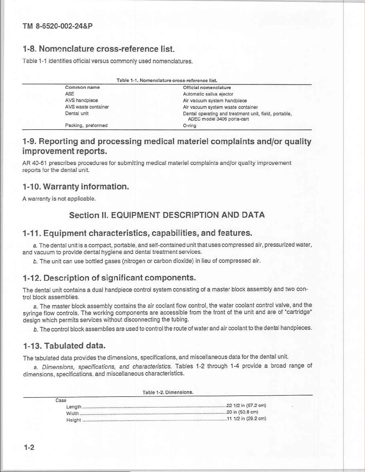
1-8.
Nomenclature
Table
1-1
identifies
Common
ASE
AVS
AVS
Dental
1-9.
Reporting
Packing,
improvement
AR
40-61
prescribes
reports
for
the
dental
cross-reference
official
versus
name
handpiece
waste
container
unit
preformed
and
processing
reports.
procedures
unit.
commonly
Table
for
submitting
used
1-1.
Nomenclature
medical
medical
list.
nomenclatures.
cross-reference
Official
Automatic
Air
vacuum
Air
vacuum
Dental
ADEC
O-ring
materiel
materiel
complaints
list.
nomenclature
saliva
ejector
system
handpiece
system
waste
operating
model
3406
and
treatment
porta-cart
complaints
and/or
container
unit, field,
and/or
quality
improvement
—
portable,
quality
1-10.
Awarranty
1-11.
and
1-12.
The
trol
syringe
design
1-13.
The
dimensions,
Warranty
Equipment
a.
The
dental
vacuum
b.
The
unit
Description
dental
block
assemblies.
master
The
a.
flow
which
control
The
b.
Tabulated
tabulated
Dimensions,
a.
information.
is
not
applicable.
Section
characteristics,
unit
is a compact,
to
provide
can use
unit
contains a dual
controls.
permits
block
The
services
block
dental
bottled
assembly
assemblies
data.
provides
data
specifications,
specifications,
II.
EQUIPMENT
portable,
hygiene
gases
of
significant
handpiece
working
without
the
and
and
(nitrogen
contains
components
disconnecting
are
dimensions,
and
miscellaneous
DESCRIPTION
capabilities,
and
self-contained
dental
treatment
or
carbon
components.
control
used
characteristics.
system
coolant
air
the
accessible
are
the
control
to
specifications,
characteristics.
the
unit
that
services.
dioxide)
consisting
flow
tubing.
route
Tables
in
control,
from
water
of
miscellaneous
and
1-2
AND
and
features.
uses
compressed
lieu
of
compressed
of a master
water
the
of
front
the
coolant
air
and
through
block
coolant
the
data
1-4
DATA
air,
air.
assembly
control
and
unit
the
to
the
for
provide
pressurized
and
two con-
valve,
"cartridge"
of
are
handpieces.
dental
unit.
dental
broad
a
water,
and
range
the
of
Table
1-2.
Dimensions.
22
0
1
1/2
in
in
(50.8
1/2
in
(57.2
cm)
cm)
(29.2
cm)
Page 9
TM
8-6520-002-24&P
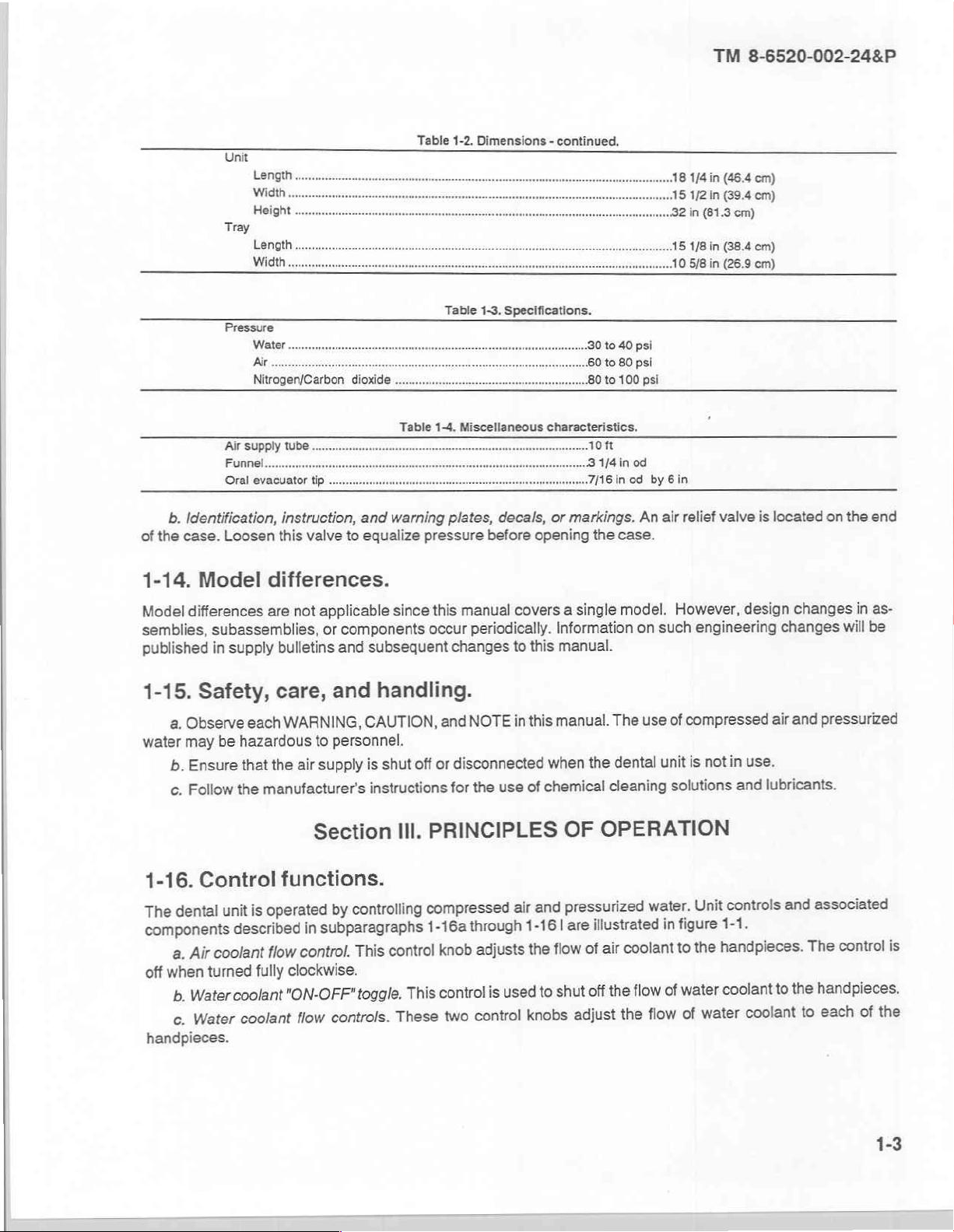
Table
1-2,
Dimensions - continued.
Unit
Length..
Width
Height.
Tray
Air
Funnel...
Oral
Length..
Width
supply
tube
evacuator
tip
Table
Table
1-3.
1-4.
Miscellaneous
Specifications.
characteristics,
он
3
1/4
in
od
7116
in
od
by
6in
b.
Identification,
of
the
case.
1-14.
Model
semblies,
published
1-15.
water
1-16.
The
components
off
handpieces.
Model
differences
Safety,
Observe
а.
may
Ensure
b.
Follow
с.
Control
dental
Air
a.
when
turned
Water
b.
Water
c.
instruction,
Loosen
this
valve
differences.
not
are
subassemblies,
supply
in
bulletins
care,
WARNING,
each
be
hazardous
that
manufacturer's
the
the
to
air
Section
functions.
operated
is
unit
described
coolant
fully
coolant
coolant
in
control.
flow
clockwise.
"ON-OFF"
flow
and warning
to
equalize
applicable
components
or
and
and
personnel.
supply
since
subsequent
handling.
CAUTION,
shut
is
instructions
III.
controlling
by
subparagraphs
control
This
toggle.
controls.
This
These
plates,
pressure
this
occur
changes
and
or
off
for
decals,
before
manual
periodically.
NOTE
disconnected
use
the
PRINCIPLES
compressed
through
1-16a
adjusts
knob
used
two
is
control
control
or
opening
covers
to
this
this
in
when
chemical
of
and
air
1-16
flow
the
to
knobs
markings.
the
case.
model.
single
a
Information
manual.
manual.
OF
pressurized
|
shut
The
dental
the
cleaning
OPERATION
illustrated
are
coolant
air
of
the
off
adjust
the
flow
An
air
such
on
use
unit
water.
in
of
flow
relief
valve
However,
engineering
compressed
of
in
not
is
solutions
controls
Unit
1-1.
figure
handpieces.
the
to
coolant
water
water
of
is
located
design
changes
air
use.
lubricants.
and
and
to
coolant
on
the
changes
will
pressurized
and
associated
control
The
handpieces.
the
each
to
in
of
end
as-
be
is
the
Page 10
TM
8-6520-002-24&P
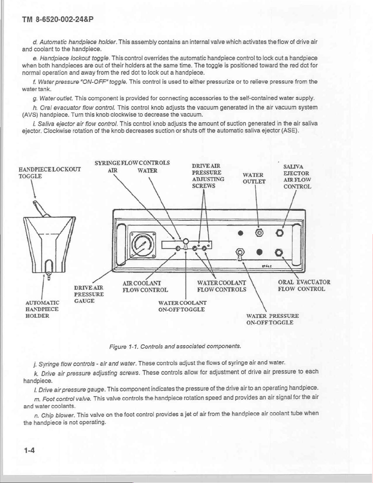
d,
Automatic
and coolant
e.
when
normal
f.
water
g.
h.
(AVS)
i.
ejector.
to
the
Handpiece
both
handpieces
operation and
Water
pressure
tank.
Water
outlet.
Oral
evacuator
handpiece.
Saliva
ejector
Clockwise
handpiece
handpiece.
lockout
Turn
rotation
are
away
"ON-OFF"
This
component
fiow
this
air
flow
toggle.
holder.
This
out
of
their
from
the red
toggle.
control.
knob
clockwise
control.
of
the
knob
This
assembly
control
holders
dot
This
is
provided
This
control
This
control
decreases
overrides
at
the
to
lock
control
for
knob
to
decrease
knob
contains
same
out a handpiece.
is
connecting
suction
an
the
automatic
time.
used
to
adjusts
the
vacuum.
adjusts
or
shuts
internal
either
accessories
the
the
handpiece
The
toggle
pressurize
vacuum
amount
off
the
valve
which
is
to
the
generated
of
suction
automatic
activates
control
positioned
or
to
toward
to
relieve
self-contained
in
the
generated
saliva
the
flow
lock
out a handpiece
the
pressure
water
air
vacuum
in
the
ejector
(ASE).
of
drive
red
dot
from
supply.
system
air
saliva
air
for
the
HANDPIECELOCKOUT
TOGGLE
AIR
DRIVE
PRESSURE
AUTOMATIC
HANDPIECE
HOLDER
GAUGE
SYRINGE
AIR
A
FLOW
CONTROLS
WATER
NN
5
AIRCOOLANT
CONTROL
FLOW
SN
WATER
ON-OFFTOGGLE
DEAR
PRESSURE
ADJUSTING
SCREWS
¿15%
WATER
FLOW
COOLANT
1
Nİ
Sy
CONTROLS
WATER
OUTLET
s
$
\
COOLANT
WATER
ON-OFFTOGGLE
ぁ
る
e
sua
・
SALIVA
EJECTOR
AIR
CONTROL
/
gll
NS
ORAL
FLOW
PRESSURE
FLOW
S
EVACUATOR
CONTROL
Syringe
i.
Drive
k.
handpiece.
air
Drive
I
Foot
m.
and
water
coolants.
Chip
n.
the
handpiece
1-4
controls
flow
pressure
air
pressure
control
blower.
is
not
-
adjusting
gauge.
This
valve.
valve
This
operating.
and
air
This
valve
on the
Figure
water.
screws.
component
controls
foot
1-1.
Controls
These
control
controls
These
indicates
handpiece
the
provides
and
associated
adjust
controls
the
jet
a
flows
the
for
allow
pressure
of
speed
air
rotation
componenits.
syringe
of
air
drive
provides
and
handpiece
of
adjustment
the
of
the
from
and
air
drive
an
to
an
water.
pressure
air
operating
signal
air
coolant
air
each
to
handpiece.
air
the
for
when
tube
Page 11
TM
8-6520-002-24&P
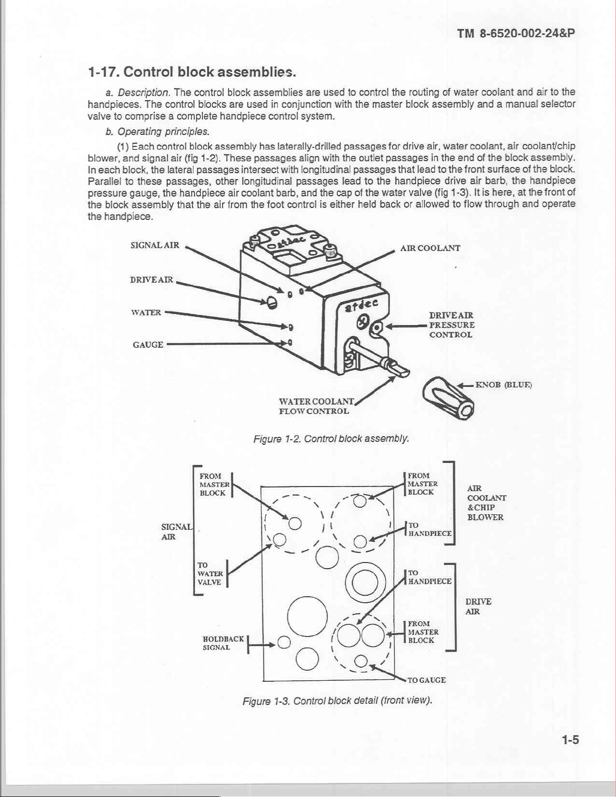
1-17.
handpieces.
valve
blower,
In
Parallel
pressure
the
the
Control
a.
Description.
to
comprise a complete
b.
Operating
(1)
Each
and
each
block,
to
these
gauge,
block
assembly
handpiece.
SIGNABAIR
DRIVEAIR
WATER
GAUGE
block
The
The
control
principles.
control
signal
air
(fig
the
lateral
passages,
the
handpiece
that
assemblies.
control
block
passages
the
blocks
handpiece
assembly
1-2).
These
other
air
block
are
air
from
assemblies
used
in
conjunction
control
has
laterally-drilled
passages
intersect
longitudinal
coolant
the
with
barb,
foot
passages
control
are
used
to
with
system.
passages
align with the
longitudinal
and
the
is
passages
lead
cap
of
either
control
the
master
outlet
to
the
the
water
held
back
the
routing
block
for
drive
passages
that
lead
handpiece
valve
or
allowed
AIR
COOLANT
—
of
water
assembly
air,
water
in
the
end
to
the
front
drive
(fig
1-3).
to
flow
DRIVEAR
PRESSURE
CONTROL
coolant and
and a manual
coolant,
of
air
Itis
air
the
block
surface
barb,
the
here,
through
at
air
to
the
selector
coolant/chip
assembly.
of
the
block.
handpiece
the
front
of
and
operate
FROM
MASTER
BLOCK
WATER
FLOW
Figure
M
I
SIGNAI
AIR
\
x
P
TO
WATER
VALVE
HOLDBACK
SIGNAL
|
>
O
1-2.
—
O
O
COOLANT,
CONTROL
Control
~
Xi
gı
x
O
00;
\
x
block
-
¿O
©
一
一
^
Os
assembly.
№
1
A
Tİ
HANDPIECE
7
x
x
1
/
TO
FROM
MASTER
BLOCK
To
HANDPIECE,
FROM
а
BLOCK
GAUGE
ペー
KNOB
AIR
COOLANT
&CHIP
BLOWER
DRIVE
AIR
(BLUF)
Figure
1-3.
Control
block
detail
(front
view).
1-5
Page 12
TM
8-6520-002-24&P
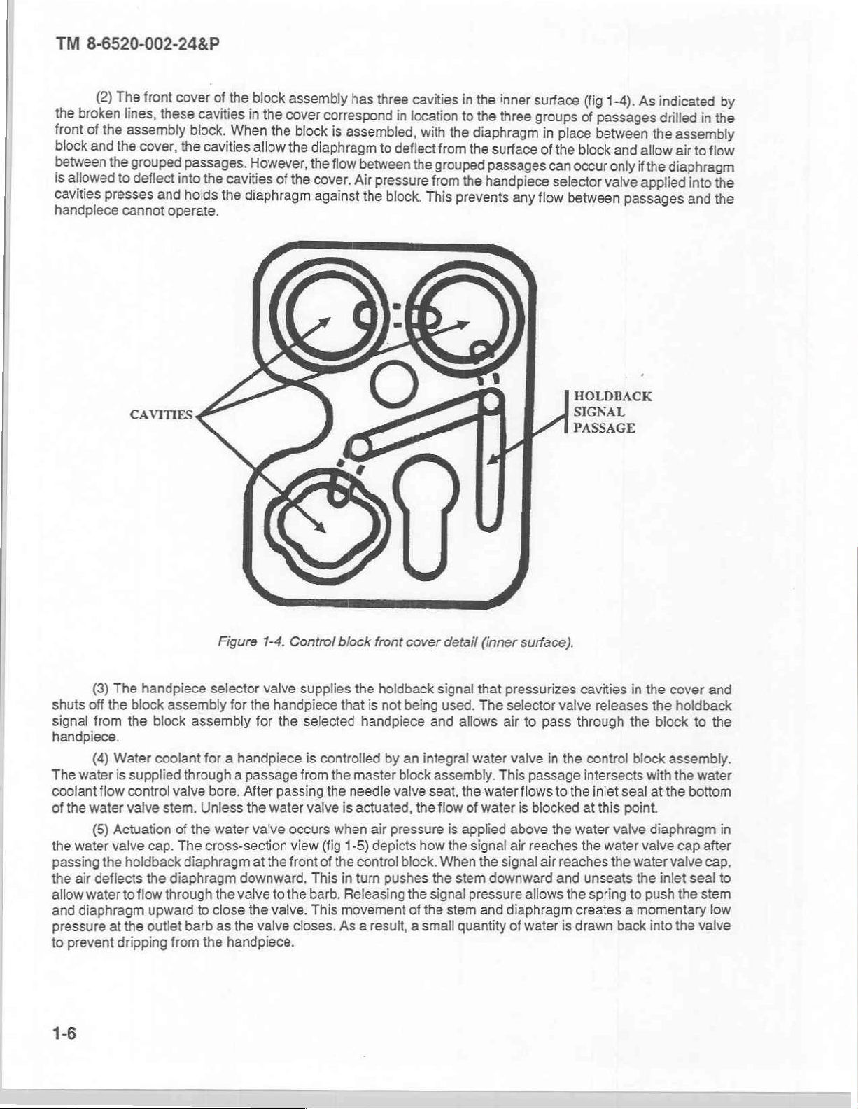
(2)
The
the
broken
front
block
between
is
allowed
cavities
handpiece
of
the
and
the
presses
lines,
assembly
the
cover,
grouped
to
deflect
cannot
front
these
and
operate.
cover
of
cavities
block.
the
cavities
passages.
into
the
holds
the
block
in
the
When
allow
However,
cavities
the
diaphragm
assembly
cover
the
block
the
of
the
has
correspond
is
assembled,
diaphragm
the
flow
between
cover.
Air
against
the
three
cavities
in
location
with
to
deflect
the
pressure
block.
This
in
to
the
from
grouped
from
the
prevents
the
inner
the
three
diaphragm
the
surface
passages
handpiece
any
surface
groups
in
place
of
the
block
can
occur
selector
flow
between
HOLDBACK
SIGNAL
PASSAGE
(fig
1-4).
of
passages
between
and
only
valve
As
indicated
drilled
the
assembly
allow
air
if
the
diaphragm
applied
passages
in
to
flow
into
and
by
the
the
the
(3)
The
handpiece
shuts
off
the
block
signal
from
the
handpiece.
(4)
Water
The
water
is
supplied
coolant
of
the
passing
the
allow
and
pressure
to
flow
the
water
(5)
water
the
air
deflects
water
diaphragm
at
prevent
control
valve
Actuation
valve
cap.
holdback
the
to
flow
upward
the
outlet
dripping
Figure
selector
assembly
block
coolant
through a passage
valve
stem.
of
The
diaphragm
diaphragm
through
barb
from
for
assembly
for a handpiece
bore.
Unless
the
water
cross-section
the
to
close
as the
the
handpiece.
1-4.
Control
valve
the
handpiece
for
the
After
passing
the
water
valve
occurs
view
at
the
front
downward.
valve
to
the
the
valve.
valve
supplies
selected
is
controlled
from
the
the
valve
when
(fig
of
the
This
barb.
This
closes.
block
front
cover
detail
the
holdback
that
is
not
handpiece
by an
master
needle
is
1-5)
in
Releasing
movement
As a result, a small
valve
actuated,
air
pressure
depicts
control
turn
pushes
being
and
integral
block
seat,
the
how
block.
the
the
signal
of
the
signal
used.
assembly.
flow
When
stem
(inner
that
The
allows
water
the
water
of
water
is
applied
the
signal
the
stem
downward
pressure
and
quantity
surface).
pressurizes
selector
air
to
pass
valve
in
This
passage
flows
to
is
blocked
above
air
signal
diaphragm
of
the
reaches
air
allows
water
cavities
valve
through
the
control
intersects
the
at
water
the
reaches
and
unseats
the
spring
creates a momentary
is
drawn
in
releases
the
block
inlet
seal
this
point.
valve
water
valve
the
water
the
to
back
the
the
with
at
diaphragm
push
into
cover
holdback
block
to
assembly.
the
water
the
bottom
cap
valve
inlet
seal
the
stem
the
valve
and
the
in
after
cap,
to
low
Page 13
TM
8-6520-002-24&P
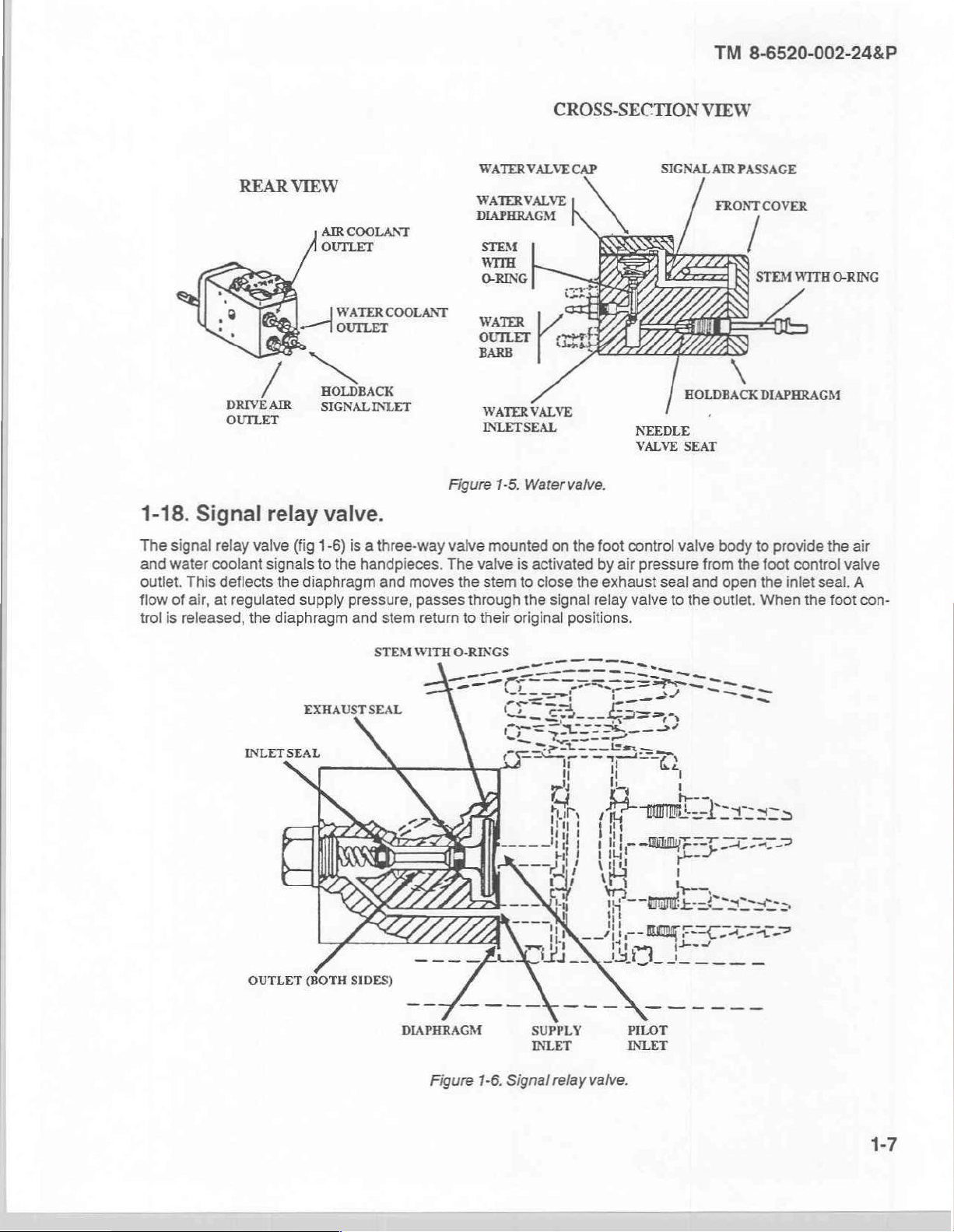
1-18.
The
and water
outlet.
flow
trol
Signal
signal
This
of
air,
is
released,
È
DRIVE
OUTLET
relay
valve
coolant
deflects
at
regulated
the
AIR
relay
(fig
1-6)
signals
to
the
diaphragm
supply
diaphragm
AIR
COOLANT
OUTLET
he
COOLANT
HOLDBACK
SIGNALINLET
valve.
is a three-way
the
handpieces.
and
pressure,
and
stem
moves
passes
return
WATER
‘WATER
DIAPHRAGM
STEM
WITH
O-RING
У,
OUTLET
BARB
‘WATER
INLET
Figure
valve
mounted
The
valve
the
stem
through
to
their
VALVE
VALVE
VALVE
SEAL
1-5.
Watervalve.
is
activated
to
close
the
original
CROSS-SECTION
CAP
SIGNAL
NEEDLE
VALVE
on the foot
the
signal
positions.
control
by
air
exhaust
relay
pressure
seal
valve
VIEW
HOLDBACK
SEAT
valve
from
and
to
the
AIR
PASSAGE
FRONTCOVER
STEM
\
DIAPHRAGM
body
to
the
foot
open
the
outlet.
When
WITH
provide
control
inlet
seal.
the foot
O-RING
the
air
valve
A
con-
INLETSEAL
EXHAUST
STEM WITH
SEAL
DIAPHRAGM
O-RINGS
Figure
1-6.
SUPPLY
INLET
Signal
relay
PILOT
INLET
valve.
Page 14
TM
8-6520-002-24&P
2-1.
Initial
Detailed
procedures
paragraph
a.
Start-up
(1)
(2)
(3)
(4)
(6)
(6)
(7)
(8)
(8)
(10)
amount
flow
of
control
(11)
OPERATING
Section
procedures.
for
unpacking,
3-7.
Procedures
procedures.
Ensure
Depress
Remove
Replace
Install a sterilized
Connect
Turn
Check
Check
suction
Only
the
Check
knob.
Check
that the
sterilize
the
the
generated
the
vent
the
water
the
water
the
air
water
air
water
AVS
the
saliva
the
water
the
supply
pressure
pressure
pressure
for
shutdown
pressure
button
tank
cap and
tank
cap
syringe
two
tips
tubing
gauge
evacuator
oral
the
by
ejector
CHAPTER
|.
OPERATING
assembling,
are
"ON-OFF"
on
the
water
using a funnel,
and
ensure
tip,
an
oral
and
mouthpiece
to a supply
"ON-OFF"
for a reading
gauge
for a reading
by
handpiece
AVS
turning
by
INSTRUCTIONS
and
preparing
provided
toggle
tank
cap
that the
evacuator
NOTE
of
dry,
toggle
to
of
pressing
can
saliva
the
in
paragraph
is
turned
(fig
E-14)
fill
the
vent
tip,
and a saliva
when
patient
filtered
the
"ON"
60
to
80
of
30
AVS
the
increased
be
ejector
2
PROCEDURES
the
dental
unit
2-1c.
"OFF."
to
tank.
button
treatment
air
or
position.
psi.
to
40
psi.
handpiece
flow
air
ensure
or
that
is
not
in
ejector
bottled
button
decreased
control
for
operation
the
tank
the
locked
mouthpiece.
is
involved.
gas
regulated
to
by
vary
to
are
has
position.
from
actuate
turning
amount
the
provided
no
air
80
vacuum.
the
oral
the
of
in
pressure.
to
100
psi.
The
evacuator
suction.
Procedures
b.
technician
с.
Shutdown
Turn
(1)
Insert
(2)
panel.
Turn
(3)
turn
the
toggle
Remove
(4)
Clean
(5)
Empty
(6)
The
or
dentist
Use
of
8
the
the
to
ASE
control
during
during
procedures.
shutdown
the
shuts
patient
patient
hours.
pressure
water
quick-disconnect
the
pressure
water
the
"OFF"
position.
quick-disconnect
the
handpiece
AVS
the
waste
AVS
the
off
the
treatment.
treatment.
procedures
to
toggle
fitting
to
toggle
fitting
ASE
and
container,
suction
when
The
the
when
various
the
"OFF"
(contained
"ON"
the
and
following
by
clean
then
NOTE
turned
functions
NOTE
dental
position.
the
in
position
back
it
put
the
disinfect
and
fully
shut
is
unit
accessory
and
the
in
cleaning
clockwise.
dental
the
of
down
kit)
the
allow
accessory
procedures
it.
unit
any
for
into
water
kit,
will
period
water
the
tank
paragraph
in
controlled
be
excess
in
outlet
completely
to
on
2-2.
dental
a
by
control
the
drain;
then
Page 15
TM
8-6520-002-24&P
(7)
Clean
(8)
Ensure
the
unit
by
depressing
(9)
Clean
and
that
the
external
lubricate
the
the
the
external
syringe
surfaces.
handpieces
air
supply
air
button.
by
following
is
turned
the
off.
Disconnect
lubrication
procedures
the
tube and
in
paragraph
bleed
the
3-8.
air
pressure
from
2-2.
Cleaning,
a.
Cleaning.
(1)
External
detergent.
Abrasive
never
(2)
internal
should
detergent
should
be
thoroughly
solution.
be
flushed
The
a
hot
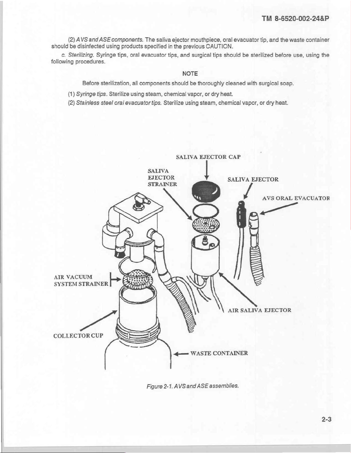
(3)
Air
vacuum
(a)
After
air
through
clean
the
it
with a hot
(b)
system
Daily.
manufacturer's
order
to
clean
the
water
has
been
(c)
Weekly.
removing
strainer,
between
any
debris.
(d)
As required.
(4)
Automatic
(8)
After
(b)
Weekly.
and
removing
b.
Disinfecting.
External
(1)
patients.
disinfecting,
surfaces.
cleansers
be
used.
assemblies
cleaned
Any
wiping
with
clear,
lubricant
detergent
each
detergent
instruction.
lower
purged
each
used
solution
system. The
patient.
for a few
solution.
Clean
the
In
portion.
from
Clean
The
saliva
ejector.
patient.
Clean
any
debris.
surfaces.
Section
All
external
and
scrubbing
and
components.
and
inspected
should
hot
water
in
the
dental
is
AVS
Rinse
seconds
AVS
handpiece
addition,
Then,
the
tubing.
the
strainer
waste
container
The
Remove
the
strainer
external
All
Il.
and
surfaces
be
done
and
then
unitis
the
most
system
the
AVS
to
remove
use
the
rinse
by
ASE
the
by
surfaces
OPERATIONAL
sterilizing
should
CAUTION
pads
will
damage
When
servicing
for
defects
with a soft,
rinsed
largely
effective
(fig
by
using a cleaner
brush
with
removing
should
system
ASE
removing
prior
lint-free
in
isopropyl
NOTE
impervious
cleaner.
2-1)
should
drawing
all
clean
water
provided
clean
water.
the
waste
be
cleaned
should
mouthpiece
the
ASE
dental
the
of
CARE
procedures.
be
cleaned
the
surface
the
dental
to
reassembly.
cloth.
alcohol.
to
chemical
be
cleaned
water
through
from
the
tubes.
with
disinfectant
in
the
accessory
Finally,
be
cleaned
and
cap,
hold
container,
each
as
clean
unscrewing
should
unit
with a solution
finishes
unit,
the
components
The
most
When
the
components
solvents.
as
follows:
the
handpiece
Remove
the
properties
kit
to
insert
the
control
unscrewing
time
it
is
emptied.
follows:
with a hot
be
detergent
the
knurled
carefully
of
hot
water
and
should
of
effective
cleaner
Therefore,
and
oral
evacuator
by
into
the
button
down
the
collector
solution.
screw
with
wiped
and
any
assembly
is a hot
are
clean,
then
drawing
tip
following
handpiece
until
all
cup,
holding
disinfectant
liquid
they
and
the
in
the
and
the
Disinfectants
part
one
phenolics
that
Clorox®
such
will
or
as
Lysol®;
not
damage
Purex©
and
CAUTION
the
surface
parts
ten
to
isopropyl
finishes
water;
of
alcohol.
include--
hypochlorite
gluteraldehyde
solution
solution;
Cydex®,
of
Page 16
(2)
should
following
be
c.
Sterilizing.
(1)
(2)
AVS
and
ASE
disinfected
Syringe
procedures.
Before
Syringe
Stainless
sterilization,
tips.
steel
components.
using
products
tips,
Sterilize
oral
evacuator
The
specified
oral
evacuator
all
components
using
steam,
saliva
chemical
tips.
Sterilize
ejector
in
the
tips,
and
should
mouthpiece,
previous
surgical
NOTE
be
thoroughly
vapor,
using
steam,
oral
CAUTION.
tips
should
or
dry
heat.
chemical
evacuator
be
cleaned
vapor,
TM
tip,
and
sterilized
with
surgical
or
dry
8-6520-002-24&P
the
waste
container
before
heat.
soap.
use,
using
the
AIR
VACUUM
SYSTEM
STRAINER
SALIVA
EJECTOR
EJECTOR
©
CAP
SALIVA
/
EJECTOR
AVS
ORAL
AIR
SALIVA
EJECTOR
EVACUATOR
COLLECTOR
CUP
Figure
==
2-1.
AVS
WASTE
and
ASE
assemblies.
CONTAINER
Page 17
TM
8-6520-002-24&P
2-3.
Operation
The
dental
Stool
Unit,
2-4.
Operation
Operation
quent
intervals
Section
unit
is
used
Dental
Operating;
Section
of
the
dental
of
PMCS.
Ill.
of
auxiliary
with
the
following
and
IV.
OPERATION
under
unit
under
OPERATION
equipment.
items
Compressor,
unusual
unusual
conditions.
conditions,
OF
of
equipment:
Dental
Operating.
UNDER
such
AUXILIARY
Light
Set,
Dental
UNUSUAL
as
in
dusty
environments,
EQUIPMENT.
Operating,
Field;
CONDITIONS
may
require
Chair
more
and
fre-
2-4
Page 18
TM
8-6520-002-24&P
3-1.
Overview.
Maintenance
unit
level
medical
quired
for
cabinet,
3-2.
Common
111
items.
3-3.
Components
and
Tools
tools
of
this
manual.
Components
functions,
the
dental
case.
and
and
of
end
both
equipment
unit
except
This
chapter
test
test
equipment
Refer
to
your
of
item
and
UNIT
Section
preventive
repairer
LEVEL
and
personnel.
for
some
provides
I.
tasks
instructions
equipment.
required
unit's
modified
end
item
basic
issue
items
CHAPTER
MAINTENANCE
GENERAL
corrective,
involving
for
maintenance
table
and
are
that
These
personnel
the
and
information
of
organization
basic issue
listed
in
3
INFORMATION
are
beyond
master
of
the
appendix
will
perform
block
to
dental
and
items.
C,
the
scope
assembly,
aid
in
unit
equipment
sections
of
the
user
the
majority
control
performing
are
listed
in
(MTOE)
II
and
III
are
assigned
of
maintenance
block
the
required
appendix
for
authorized
of
this
manual.
to
re-
assemblies,
tasks.
B,
section
3-4.
Expendable
Expendable
dix
D,
section
3-5.
Repair
Repair
3-6.
Special
3-7.
The
crepancies
case
parts
Special
tools
Inspecting
dental
a.
Unpacking
(1)
Remove
(2)
Loosen
Unlatch
(3)
Lift
(4)
aside.
Open
(5)
and
durable
II
of
this
parts.
reguired
tools.
reguired
Section
will
unit
be
must
the
the
unit
the
the
supplies.
supplies
manual.
for
unit
for
maintenance
and
unpacked,
be
reported
unit.
the
shipping
air
relief
case,
the
from
accessory
and
level
maintenance
II.
SERVICE
servicing
inspected,
accordance
in
container
valve
which
case,
and
kit
the
Also
remove
the
materials
of
the
dental
UPON
the
and
with
if
not
previously
is
located
remove
and
lid,
remove
remove
the
reguired
are
listed
unit
are
RECEIPT
unit.
serviced
instructions
the
on
the
the
waste
the
inch
3/4
for
maintenance
in
appendix
listed
described
as
given
removed.
end
of
protective
container,
open-end
E,
in
appendix
OF
in
in
the
case.
foam
accessory
wrench.
of
the
dental
section
II
E,
section
EQUIPMENT
following
the
40-61.
AR
pad.
kit,
unit
are
of
this
manual.
III
of
subparagraphs.
post
and
listed
in
appen-
this
manual.
assembly.
Dis-
Set
the
3-1
Page 19
TM
8-6520-002-24&P
(6)
Remove
(7)
Fasten
time.
same
foot
(8)
Stand
(9)
Install
(10)
Remove
the foot
the
unit.
performing
procedures.
control
(11)
Set
(12)
Lift
(13)
Loosen
(14)
Locate
(15)
Uncoil
ASE
tip
and
(16)
Feed
(17)
Install
(18)
Screw
(19)
Connect
(20)
Secure
b.
Inspecting
(1)
Perform a visual
(2)
Check
(3)
Perform a thorough
the
(4)
Report
©.
Servicing
For
maximum
pads
the
the
tubing
the
off
the
the
the
initial
the
the
the
Remove
holes,
dental
the top
the
and
the
AVS
the
the
the
the
damage
cap
screw
post
assembly
unit
the
and
secure
into
the
frame
base
unit
on
the
the foot
handpiece
handpieces
the
unit.
unit
procedures
unit.
control
from
inside
unit
upright.
of
the
thumbscrews
install
the
AVS
handpiece
handpiece
AVS
waste
10-foot
accessory
inspection
frame
and/or
that
secures
to
the
mobility,
foot
accessory
upright.
post
unit.
hanger
tubings
container
air
by
inspection
in
the
pads
the
by
tightening
secured
the
unit.
that
and
in
their
and
from
the
supply
kit
and
to
detect any
adjusting
paragraph
discrepancies
the
frame
frame
base
casters
using a 5/32
casters
kit.
secure
bar
case.
for
with
the
on
the
underside
the
assemblies
ASE
tubings and
hangers.
syringe
accessory
onto
tubing
it
to
leaks
2-1.
out
the
to
damage
several
in
base
to
using
the
cap
NOTE
from
the
accessory
inch
hex
wrench,
the
cap
screws
thumbscrews.
of
the
instrument
to
through
kit
onto
bottom
the
quick-disconnect
different
after
components
NOTE
hanger
the
outside
feed
the
their
of
the
which
checking
the
underside
screw
from
unit
with
bar
of
them
out
bottom
tubings.
AVS
assembly.
may
have
heights.
the
control
or
operation
of
and
wrench.
kit
may
be
insert
the
the
foot
an
elastic
assemblies
the
unit.
through
of
the
unit.
on
the
occurred
functions
in
the
unit
using
installed
casters
pads.
Place
cord.
upside
the
bottom
Place
them
short
supply
to
the
in
accordance
the
wrench.
at
this
into
the
the
Carefully
down
in
of
the
in
their
tubing
dental
paragraph
unit.
with
established
draw
the
unit.
unit.
Place
hangers.
under
1-16
and
out
the
Additional
(1)
Syringe.
(a)
(b)
(c)
(2)
Drive
PMCS
A
syringe
table
Change
Pull
the
Insert a replacement
syringe
air
pressure.
servicing
(para
the
syringe
tip
out
tip
that
when
the
instructions
3-9)
or
the
maintenance
tip
by
loosening
with a straight
tip
is
not
air
button
by
pushing
fully
seated
is
motion.
depressed.
and
procedures
the
it
completely
CAUTION
may
may
instructions
nut
approximately
into
cause
the
water
be
incorporated
(para
3-13
1/2
the
syringe
button
through
turn.
seat
to
be
into
either
para
and
tighten
ejected
the
3-23).
the
from
the
nut.
Page 20
at
the
To
preclude
handpiece
The
drive
the
faceplate
(a)
Install a dental
(b)
Operate
The
handpiece
tool
is
completed
(c)
With
maximum
pressure
Turn
counterclockwise
damage
manufacturer.
air
pressure
of
the
handpiece
actually
in
several
the
foot
control
specified
the
drive
to
the
adjusting
the
unit
(fig
tool
in
the
and
should
not
performing
steps
fully
by the
air
pressure
to
increase
unit,
adjust
screws
1-1).
handpiece
observe
be
operated
its
function.
to
prevent
depressed,
manufacturer.
adjusting
pressure.
CAUTION
the
drive
NOTE
are
located
chuck.
the
drive
CAUTION
more
than a few
The
damage
adjust
NOTE
screws
air
air
pressure
drive
to
the
the
drive
clockwise
pressure
next
to
gauge.
seconds
air
pressure
handpiece.
air
adjusting
to
the
the
water
ata
time
adjustment
to
decrease
TM
8-6520-002-24&P
specifications
coolant
unless a dental
screws
of
knobs
should
until
the
pressure
the
on
be
handpiece
or
runs
(3)
Handpiece
(a)
handpiece.
(b)
(c)
(d)
(e)
visible
to
spray
around
(f)
(4)
Syringe
(a)
(b)
increase
(c)
pattern.
Ensure
Operate
Adjust
A
Adjust
The
faceplate
flow.
the
strong
Turn
the
Operate
the
dental
the
flow.
syringe
Depress
Adjust
the
Depress
coolant
that the
the
handpiece
air
coolant
air
coolant
water
coolant
the
handpiece
tool.
second
flow
of
the
unit
the
water
water
both
buttons
flow.
water
coolant
at
medium
flow
flow
is
flow
and
handpiece
adjusting
button.
flow
(fig
1-1).
by
(air
screws
turning
toggle
as
desired.
recommended.
control
turn
by
and
water)
is
speed
NOTE
clockwise
the
water
following
NOTE
are
located
the
adjusting
simultaneously
in
the
while
until
coolant
the
preceding
above
screw
"OFF"
position
observing
it
seats
flow
control
steps.
the
air
clockwise
and
and a dental
the
preceding
softly.
counterclockwise
coolant
adjust
flow
to
decrease
the
air
tool
CAUTION
control
flow
flow
to
is
installed
.
until a fine
on
the
or
counterclockwise
achieve
the
in
mist
desired
the
is
The
syringe
water.
flow
Forcing
adjusting
the
screws
screws
to
turn
CAUTION
are
not
intended
off
the
water
or
to
completely
air
will
damage
stop
the
the
unit.
flow
of
air
and
Page 21
TM
8-6520-002-24&P
3-8.
General.
All
lubrication
internal
tings
to
should
o-rings.
the
moving
also
Section
The
unit.
3-9.
General.
a.
The
dental
at
all
times.
failure.
b.
are
things
observing
c.
each
area
on
Operation, A -
unit.
Inspection
Table
3-1
Preventive
you
for
The
following
column:
(1)
Item
the
Equipment
(2)
Interval.
Section
requirements
parts
of
mechanical
be
coated
should
bores
Seal
IV.
PREVENTIVE
PMCS
should
improper
No.
After
chart
unit
must
will
contains a list
maintenance
do
operational
is a list
This
column
Inspection
This
column
Operation, M -
for
the
before
in
this
be
inspected
allow
defects
of
is
any
time
of
the
shows
shows
III.
LUBRICATION
dental
unit
valves
they
are
lightly
be
also
section
and
to
be
PMCS
not
and
items
limited
you
see
indicators,
PMCS
Monthly, Q -
table
the
sequence
Maintenance
when
can
be
performed
and
controls
installed.
lubricated
should
This
makes
before
MAINTENANCE
NOTE
contains
serviced
discovered
to
performing
they
and
each
all
necessary
systematically
and
to
be
performed
the
need
to
maintaining
column
Quarterly.
headings
in
which
Worksheet,
PMCS
item
be
to
B, D,
INSTRUCTIONS
using
a
high
be
coated
their
inserting
with
installation
stems
CHECKS
unit
level
services
to
ensure
corrected
by
checks
done,
the
do
the
DA
is
to
and A should
before
unit
level
maintenance
and
services
such
as
proper
with a description
be
quantities
PMCS,
Form
and
2404.
serviced; B -
quality
a
light
easier
or
silicone
film
pistons.
AND
for
that the
they
result
listed
checking
of
of
is
used
Before
be
performed
base
of
silicone
and
prevents
SERVICES
the
dental
unit
is
ready
in
serious
personnel.
in
the
PMCS
for
general
operating
the
information
to
identify the
Operation, D -
with
grease.
grease.
damage
for
operation
damage
table.
There
cleanliness,
supplies.
found
equipment
During
daily
use
All
of
O-
or
in
the
When
the
items
that
when
the
(3)
Item
to
be
Inspected
checked
or
ITEM
NO
or
serviced.
(4)
Equipment
unusable.
BIDIA
1
x
is
INTERVAL
| M |Q
x
equipment
Will
equipment
not
x
must
not
disrupt
can
and
Ready/Available
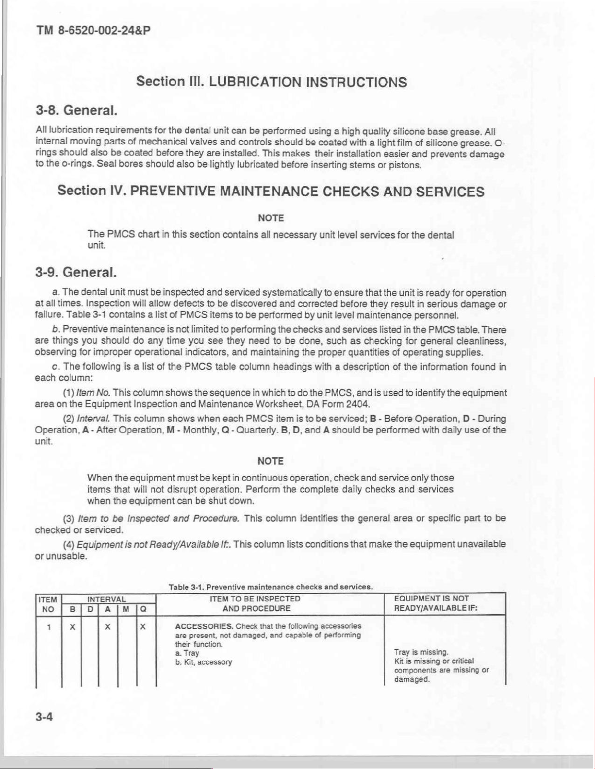
Table
ACCESSORIES.
are
their
a.
b.
be
kept
operation.
be
shut
Procedure.
If..
3-1.
Preventive
ITEM
AND
present,
not
function.
Tray
Kit,
accessory
NOTE
in
continuous
Perform
down.
This
This
column
maintenance
TO BE
INSPECTED
PROCEDURE
Check
that
damaged,
operation,
the
column
lists
the
following
and
capable
check
complete
identifies
conditions
checks
and services.
accessories
of
performing
and
daily
the
general
that
service
checks
make
only
those
and
services
area
or
specific
the
equipment
EOUIPMENT
READY/AVAILABLE
IS
-
Tray
is
missing.
Kit
is
missing
components
damaged.
or
are
part
to
be
unavailable
NOT
IF:
critical
missing
or
Page 22
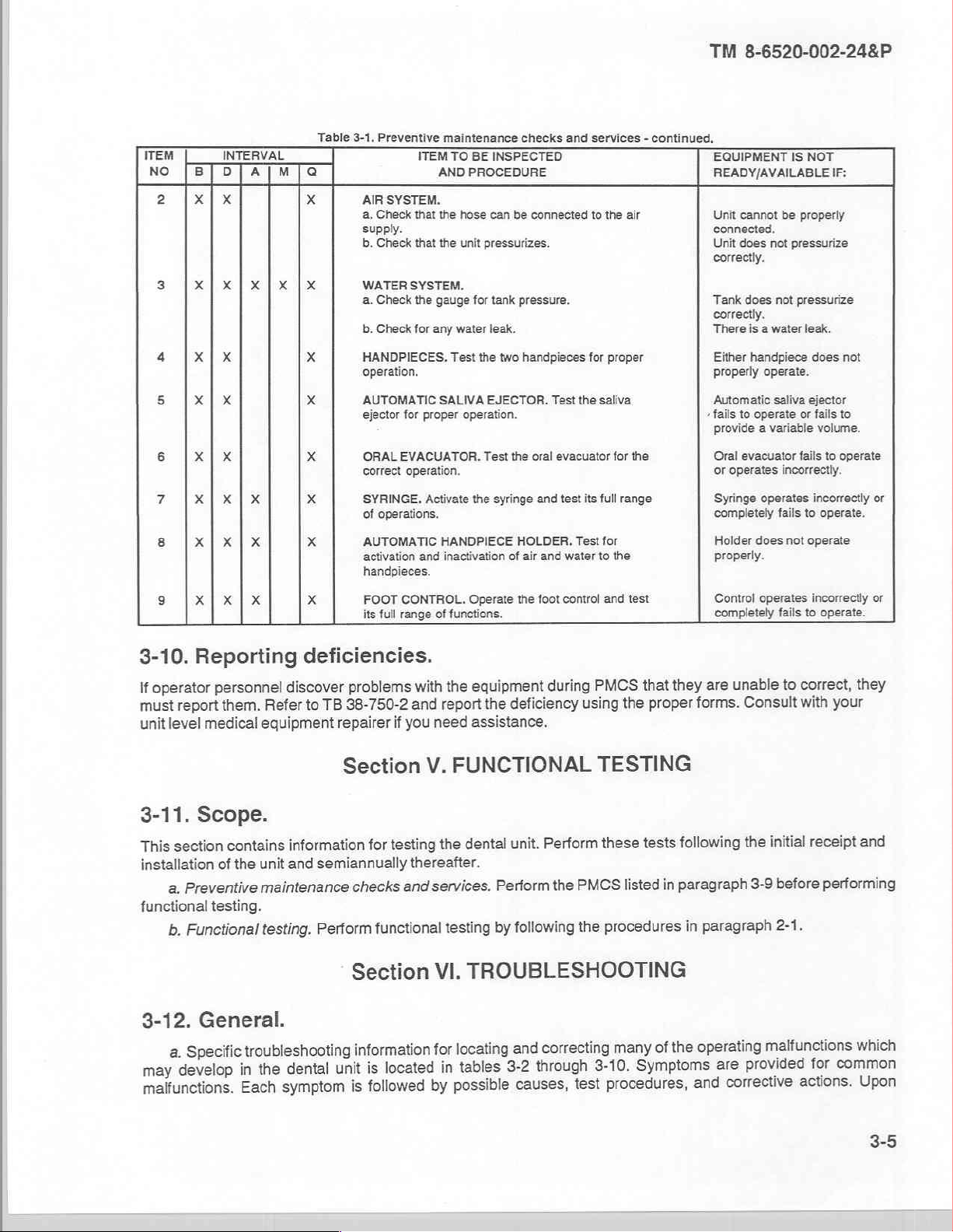
ITEM
no
2
[By]
|x|x
INTERVAL
D]A|M
Table
3-1.
Preventive
AIR
SYSTEM.
a.
Check
supply.
b.
Check
maintenance
ITEM
AND
that
the
that
the
TO
BE
INSPECTED
PROCEDURE
hose
can
be
unit
pressurizes.
checks
and
connected
services - continued.
to
the
air
TM
8-6520-002-24&P
EQUIPMENT
READY/AVAILABLE
Unit
cannot
connected.
Unit
does
correctly.
IS
NOT
IF:
be
properly
not
pressurize
4 X | X
5
X | X
6
X | X
了
X|X|X
3-10.
operator
If
report
must
unit
level
Reporting
personnel
them.
medical
Refer
equipment
deficiencies.
to
TB
problems
38-750-2
repairer
discover
WATER
a.
b.
HANDPIECES.
operation.
AUTOMATIC
ejector
ORAL
correct
SYRINGE.
of
AUTOMATIC
activation
handpieces.
its
SYSTEM.
Check
the
gauge
Check
for
any
water
Test
SALIVA
for
proper
EVACUATOR.
operation.
operations.
FOOT
Activate
and
CONTROL.
full
range
with
and
you
if
HANDPIECE
inactivation
of
functions.
the
report
need
operation.
for
tank
pressure.
leak.
the
two
handpieces
EJECTOR.
Test
the
oral
the
syringe
and
HOLDER.
of
air
and
Operate
the
foot
equipment
the
assistance.
during
deficiency
for
proper
Test
the
saliva
evacuator
test
water
control
its
full
Test
for
to
and
PMCS
using
for
range
the
the
test
that
the
Tank
‘There
+
fails
are
they
forms.
proper
does
not
correctly.
is a water
Either
handpiece
properly operate.
Automatic
to
provide a variable
Oral
evacuator
or
operates
Syringe
completely
Holder
properly.
Control
completely
unable
Consult
pressurize
leak.
does
saliva
operate
operates
does
operates
ejector
or
fails
volume.
fails
incorrectly.
incorrectly
fails
to
not
operate
incorrectly
fails
to
correct,
to
with
to
operate
operate.
operate.
your
not
to
or
or
they
3-11.
This
installation
functional
3-12.
may
maifunctions.
Scope.
section
of
Preventive
a.
testing.
Functional
b.
General.
Specific
a.
develop
contains
the
Section
information
unit
and
semiannually
maintenance
testing.
troubleshooting
the
in
Each
Perform
dental
symptom
unit
V.
testing
for
thereafter.
checks
Section
information
is
and
functional
located
is
followed
FUNCTIONAL
Perform
dental
the
services.
testing
VI.
locating
for
tables
in
possible
by
unit.
Perform
following
by
TROUBLESHOOTING
correcting
and
through
3-2
causes,
the
PMCS
the
test
TESTING
tests
these
in
listed
procedures
of
many
Symptoms
3-10.
procedures,
following
paragraph
paragraph
in
operating
the
are
corrective
and
receipt
initial
the
before
3-9
2-1.
malfunctions
provided
actions.
and
performing
which
common
for
Upon
3-5
Page 23
TM
8-6520-002-24&P
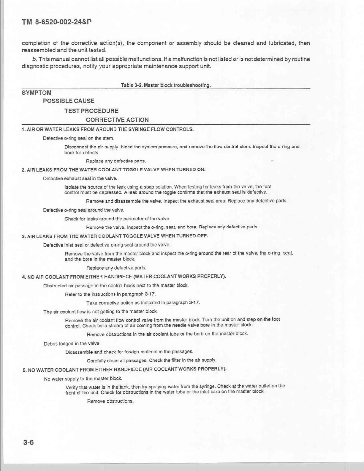
completion
reassembled
b.
This
manual
diagnostic
SYMPTOM
1,
AIR
2.
AIR
procedures,
POSSIBLE
OR
WATER
Defective
LEAKS
Defective
Defective
3.
AIR
LEAKS
Defective
4,
NO
AIR
COOLANT
Obstructed
The
Debris
WATER
NO
5,
No
of
the
corrective
and
the
cannot
CAUSE
TEST
LEAKS
o-ring
Disconnect
bore
for
FROM
THE
exhaust
Isolate
control
o-ring seal
Check
FROM
THE
inlet
seal
Remove
and
the
FROM
air
passage
Refer
air
coolant
Remove
control.
lodged
in
Disassemble
COOLANT
water
supply
Verify
front
action(s),
unit
tested.
list
all
notify
your
PROCEDURE
CORRECTIVE
FROM
AROUND
seal
on
the
stem.
the
air
defects.
Replace
WATER
the
seal
must
COOLANT
in
the
source
be
depressed, A leak
Remove
around
for
leaks
around
Remove
WATER
COOLANT
or
defective
the
valve
bore
in
the
Replace
EITHER
in
the
to
the
instructions
Take
corrective
flow
is
not
getting
coolant
air
the
for
Check
Remove
the
valve.
and
Carefully
EITHER
FROM
to
the
master
is
water
that
the
of
Check
unit.
Remove
the
component
possible
supply,
any defective
valve.
of
the
and
the
the
malfunctions.
appropriate
Table
3-2.
ACTION
THE
SYRINGE
bleed
the
system
parts.
TOGGLE
leak
using a soap
around
disassemble
the
valve.
the
perimeter
valve.
Inspect
TOGGLE
o-ring
seal
around
from
the
master
block
master
block.
any
defective
HANDPIECE
control
in
to
flow
stream
a
obstructions
check
clean
parts.
(WATER
block
next
paragraph
action
as
indicated
the
master
valve
control
coming
air
of
in
the
for
foreign
material
all
passages.
HANDPIECE
block.
try
then
tank,
the
in
obstructions
for
obstructions.
or
If a malfunction
maintenance
Master
block
troubleshooting.
FLOW CONTROLS.
pressure,
VALVE
WHEN
solution.
the
toggle
valve.
Inspect
of
the
valve.
the
o-ring,
seat,
VALVE
WHEN
the
valve.
and inspect
COOLANT
to
the
master
3-17.
in
paragraph
block.
master
the
from
from
air
coolant
Check
COOLANT
(AIR
spraying
in
the
in
the
the
water
the
water
needle
tube
passages.
filter
assembly
support
and
remove
TURNED
When
testing
confirms
the
exhaust
and
bore.
TURNED
the
o-ring
WORKS
block.
3-17.
block.
valve
or
the
barb
in
the
WORKS
the
from
the
or
tube
should
is
unit.
the
ON.
for
that
the
seal
Replace
not
listed
flow
leaks
exhaust
area.
any
be
control
from
defective
OFF.
around
the
rear
PROPERLY).
Turn
bore
on
air
supply.
the
in
the
master
master
unit
the
PROPERLY).
Check
syringe.
inlet
on
barb
cleaned
or
is
notdetermined
stem.
the
valve,
seal
is
defective.
Replace
any
parts.
of
the
valve,
step
and
on
block.
block.
water
the
at
master
the
and
lubricated,
Inspect
the
o-ring
the
foot
defective
on
parts.
the
o-ring
foot
the
the
on
outlet
block.
by
routine
and
seat,
then
3-6
Page 24
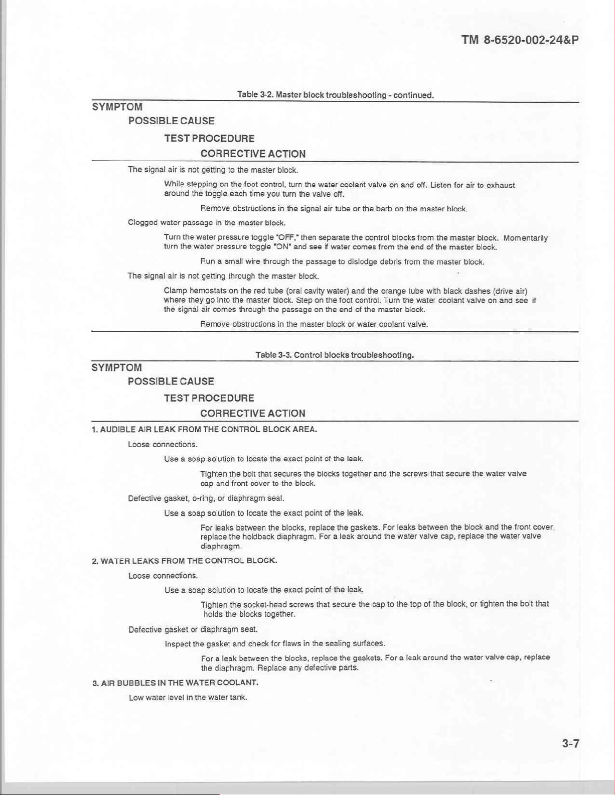
SYMPTOM
POSSIBLE
The
Clogged
The
TEST
signal
air
While
around
water
Turn
turn
signal
air
Clamp
where
the
CAUSE
PROCEDURE
CORRECTIVE
is
not
getting
to
stepping
passage
the
the
is
not
they
signal
on
the
the
toggle
each
Remove
in
the
water
pressure
water
pressure
Run a small
getting
through
hemostats
go
into
air
comes
Remove
on
Table
3-2.
Master
ACTION
the
master
block.
foot
control,
time
obstructions
master
toggle "OFF,"
toggle
wire
the
the red
the
master
through
obstructions
turn
you
tum
the
in
the
signal
block.
then
"ON"
and
through
the
master
block.
tube
(oral
block.
Step
the
passage
in
the
master
block
troubleshooting - continued.
the
water
coolant
valve
off.
air
tube
separate
see
if
water
passage
cavity
water)
on
the
on
the
block
valve
or
the
the
control
comes
to
dislodge
and
the
foot
control,
end
of
the
or
water
barb
from
debris
orange
Turn
master
coolant
on
and
off.
on
the
master
blocks
from
the
end
from
tube
the
water
block.
valve.
Listen
block.
the
master
of
the
master
the
master
with
black
coolant
TM
for
air
block.
block.
È
dashes
valve
8-6520-002-24&P
to
exhaust
block.
Momentarily
(drive
air)
on
and see
if
SYMPTOM
POSSIBLE
1,
AUDIBLE
Loose
Defective
2.
WATER
3.
AIR
LEAKS
Loose
Defective
BUBBLES
Low
CAUSE
TEST
PROCEDURE
AIR
LEAK
FROM
connections.
Use a soap
gasket,
o-ring,
Use a soap
FROM
THE
connections.
Use a soap
gasket
or
Inspect
IN
THE
WATER
water
level
in
Table
CORRECTIVE
THE
CONTROL
solution
to
locate
Tighten
the
cap
solution
For
replace
diaphragm.
CONTROL
solution
Tighten
holds
diaphragm
the
gasket
For a leak
the
the
water
bolt
and
front
cover
or
diaphragm
to
locate
leaks
between
the
holdback
BLOCK.
to
locate
the
socket-head
the
blocks
seat.
and
check
between
diaphragm.
COOLANT.
tank,
3-3.
Control
ACTION
BLOCK
AREA.
the
exact
that
secures
to
seal.
the
the
the
together.
for
the
Replace
the
the
block.
exact
blocks,
diaphragm,
exact
screws
flaws
in
blocks,
any
blocks
troubleshooting.
point
of
the leak.
blocks
together
point
of
the
leak.
replace
the
For a leak
point
that
the
replace
defective
gaskets.
around
of
the leak.
secure
sealing
surfaces.
the
gaskets.
parts.
and
the
cap
the
screws
For
leaks
the
to
between
water
valve
the
top
For a leak
that
secure
the
cap,
of
the
block,
around
the
the
water
block
and
replace
the
or
tighten
water
valve
valve
the
front
water
valve
the
bolt
cap,
replace
cover,
that
3-7
Page 25
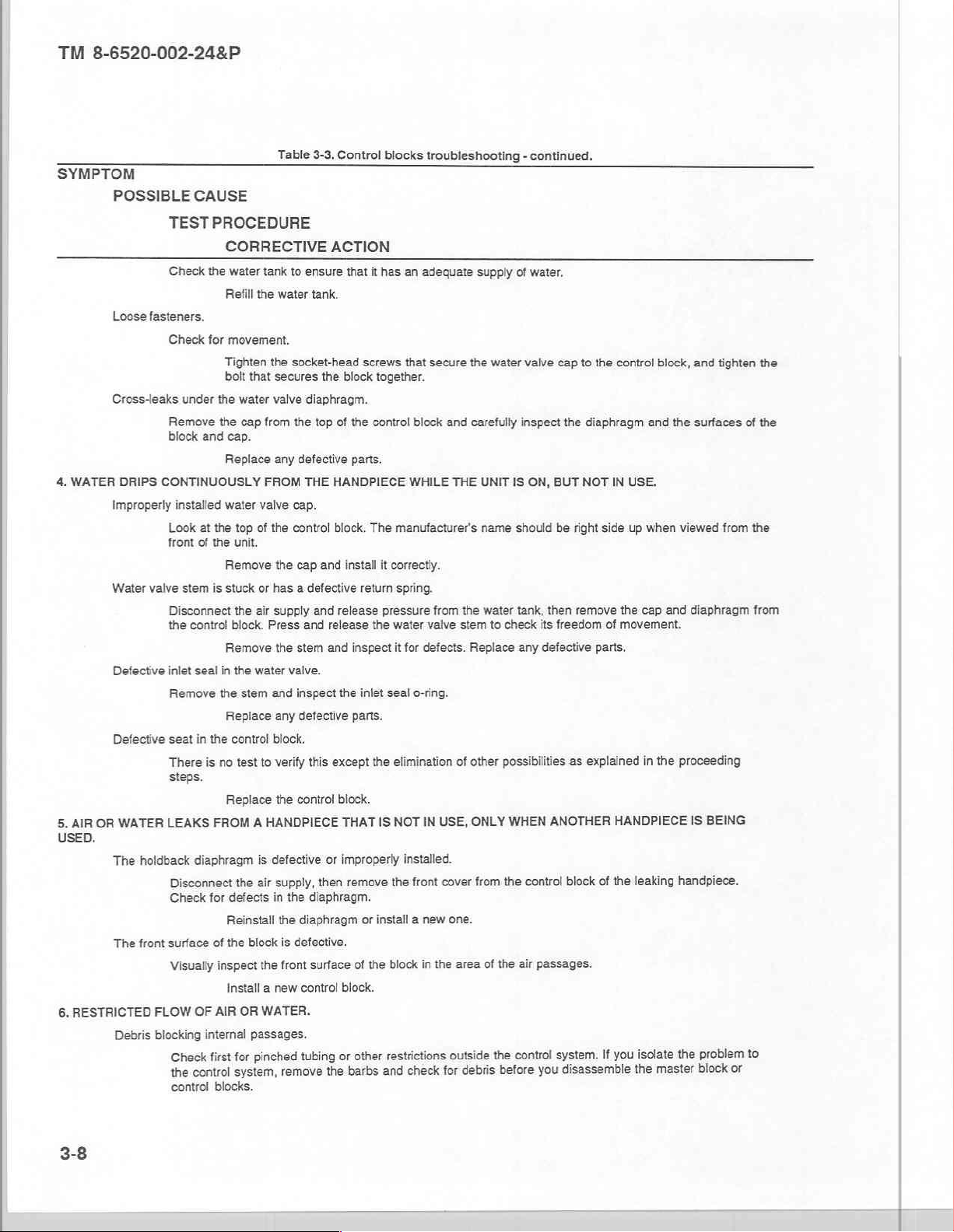
TM
8-6520-002-24&P
SYMPTOM
POSSIBLE
Loose
fasteners.
Cross-leaks
4.
WATER
DRIPS
Improperly
Water
valve
Defective
Defective
WATER
OR
AIR
5.
USED.
The
holdback
The
front
6.
RESTRICTED
FLOW
Debris
blocking
CAUSE
TESTPROCEDURE
CORRECTIVE
Check
the
water
tank
Refill
the
Check
for
movement.
Tighten
the
bolt
that
under
the
water
Remove
block
and
the
cap.
cap
from
Replace
CONTINUOUSLY
installed
Look
at
the
front
of
the
FROM
water
valve
top
of
unit.
Remove
stem
is
stuck
or
Disconnect
the
the
control
block.
air
Press
Remove
inlet
seal
in
the
water
Remove
seat
There
in
the
is
the
no
stem
Replace
control
test
to
steps.
Replace
HANDPIECE
A
FROM
LEAKS
diaphragm
Disconnect
Check
for
is
the
air
defects
Reinstall
surface
of
the
block
Visually
inspect
the
Install a new
OF
AIR
OR
WATER.
internal
passages.
pinched
for
first
Check
the
control
control
blocks.
system,
Table
3-3,
Control
ACTION
to
ensure
that
it
has
water
tank.
socket-head
secures
valve
diaphragm.
the
top
any defective
THE
screws
the
block
together.
of
the
control
parts.
HANDPIECE
cap.
the
control
block.
The
the
cap and
has a defective
supply
the
stem
install
retum
and
release
and
release
and inspect
it
pressure
the
valve.
and
inspect
the
inlet
any defective
parts.
block.
verify
this
except
the
the
control
block.
IS
THAT
defective
supply,
in
or
improperly
then
the
the
is
defective.
front
remove
remove
diaphragm.
diaphragm
surface
of
control
block.
other
or
tubing
the
barbs
or
install a new
the
and
blocks
troubleshooting - continued.
an
adequate
that
secure
block
WHILE
manufacturer's
the
and
carefully
THE
supply
water
UNIT
name
correctly.
spring.
from
the
water
valve
it
for
defects.
seal
o-ring.
elimination
IN
NOT
stem
of
USE,
water
to
Replace
other
possibilities
ONLY
installed.
the front
cover
from
one.
block
in
the
area
of
the
the
check
outside
debris
for
before
restrictions
of
water.
valve cap
inspect
IS
ON,
should
tank,
check
any defective
WHEN
the
control
air
control
to
the
the
diaphragm
BUT NOT
be
right
then
remove
its
freedom
parts.
as
explained
ANOTHER
block
passages.
system.
disassemble
you
control
block,
and
IN
USE.
side
up
when
the
cap
of
movement.
in
the
HANDPIECE
of
the
leaking
isolate
you
If
the
master
and
tighten
the
surfaces
viewed
from
and
diaphragm
proceeding
BEING
IS
handpiece.
problem
the
block
or
the
of
the
the
from
to
3-8
Page 26
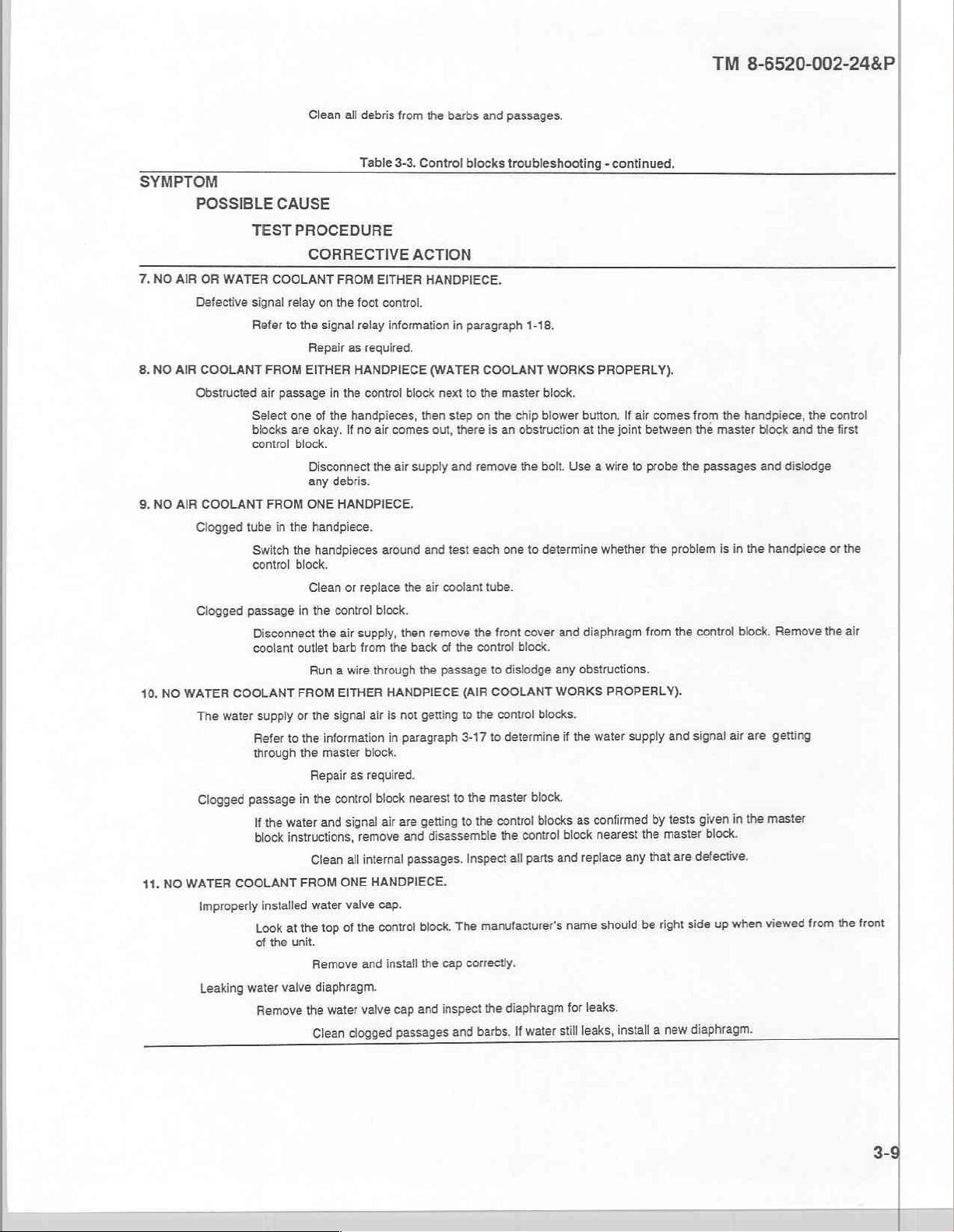
SYMPTOM
POSSIBLE
7.
NO
AIR
OR
Defective
8.
NO
AIR
COOLANT
Obstructed
9.
NO
AIR
COOLANT
Clogged
Clogged passage
10.
NO
WATER
The
Clogged
WATER
NO
41.
Improperly
Leaking
TEST
WATER
water
COOLANT
signal
Refer
FROM
air
Select
blocks
control
FROM
tube
Switch
control
Disconnect
coolant
COOLANT
supply
Refer
through
passage
the
If
block
COOLANT
installed
Look
of
the
water
Remove
Clean
all
CAUSE
PROCEDURE
CORRECTIVE
FROM
relay
on
the
to
the
signal
Repair
as
EITHER
passage
in
valve
in
the
one
of
the
okay.
handpieces,
If
are
block.
Disconnect
any
debris.
ONE
HANDPIECE.
the
handpiece.
the
handpieces
block.
Clean
or
in
the
control
the
air
outlet
barb
Run a wire
FROM
EITHER
or
the
signal
to
the
information
the
master
Repair
as
in
the
control
signal
and
water
instructions,
all
Clean
ONE
FROM
water
valve
of
top
the
at
unit.
Remove
diaphragm.
the
water
clogged
Clean
debris
from
the
Table
3-3.
Control
ACTION
EITHER
foot
relay
required.
HANDPIECE
control
no
air
the
replace
block.
supply,
from
through
air
block.
required.
block
remove
internal
HANDPIECE.
cap.
control
the
and
valve
HANDPIECE.
control.
information
(WATER
block
then step
comes
out,
air
supply
around
and
the
air
then
remove
the
back
the
HANDPIECE
is
not
getting
in
paragraph
nearest
getting
are
air
disassemble
and
passages.
block.
install
the
cap
and
passages
barbs
and
passages.
blocks
troubleshooting - continued.
in
paragraph
COOLANT
next
to
the
master
on
the
there
and
test
coolant
of
the
passage
(AIR
to
3-17
to
to
Inspect
The
cap
correctly.
inspect
and
chip
is
an
obstruction
remove
the
each
one
tube.
the front
control
block.
to
dislodge
COOLANT
the
control
to
determine
the
master
control
the
control
the
all
manufacturer's
the
diaphragm
If
barbs.
1-18.
WORKS
block.
blower
bolt.
Use a wire
to
determine
cover
and
any
WORKS
blocks.
if
block.
blocks
block
and
parts
name
for
still
water
PROPERLY).
button,
If
air
joint
to
comes
between
probe
the
the
problem
from
the
at
the
whether
diaphragm
obstructions.
PROPERLY).
the
water
supply
and
tests
confirmed
as
nearest
replace
should
the
that
any
be
by
master
are
right
leaks.
new
a
install
leaks,
TM
8-6520-002-24&P
from
the
the
control
signal
handpiece,
master
block
passages
given
block.
is
in
air
in
and
the
block.
are
the
handpiece
getting
master
defective.
viewed
when
up
side
diaphragm.
the
control
and
the
first
dislodge
or
Remove
the
from
the
air
front
the
3-9
Page 27
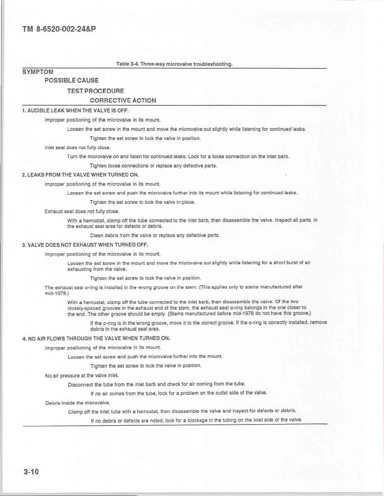
TM
8-6520-002-24&P
SYMPTOM
1,
AUDIBLE
2.
LEAKS
3.
VALVE
POSSIBLE
LEAK
Improper
Inlet
seal
FROM
Improper
Exhaust
DOES
Improper
CAUSE
TEST
PROCEDURE
WHEN
THE
positioning
Loosen
the
does
not
fully
Turn
the
microvalve
THE
VALVE
positioning
Loosen
the set
seal
does
not
With a hemostat,
the
exhaust
NOT
EXHAUST
positioning
Loosen
the
exhausting
The exhaust
seal
o-ring
mid-1978.)
With a hemostat,
closely-spaced
the
end.
The
4.
NO
AIR
FLOWS
Improper
THROUGH
positioning
Loosen
the set
No
air
Debris
pressure
inside
at
the
Disconnect
the
microvalve.
off
Clamp
Table
CORRECTIVE
VALVE
IS
OFF.
of
the
microvalve
set
screw
in
Tighten
the set
close.
on
Tighten
Tighten
Clean
Tighten
loose
WHEN
TURNED
of
the
microvalve
screw
the set
fully
close.
clamp
seal
area
debris
WHEN
of
the
microvalve
set
screw
from
the
the
is
installed
and
for
TURNED
in
valve.
set
clamp
grooves
other
groove
If
the
o-ring
is
debris
in
the
THE
VALVE
of
the
microvalve
screw
and
Tighten
the
set
vaive
inlet.
the
tube from
If
no
air
comes
tube
inlet
the
or
debris
no
If
3-4.
Three-way
ACTION
in its
the
mount
screw
to
and
listen
connections
ON,
in its
push
the
screw
to
off
the
tube
defects
or
from
the
valve
OFF.
in its
the
mount
screw
to
in
the
wrong
off
the
tube
in
the
exhaust
should
in
the
wrong
exhaust
seal
WHEN
TURNED
in its
push
the
screw
to
the
inlet
from
the
hemostat,
a
with
are
defects
microvalve
mount.
and
move
the
lock
the
valve
for
continued
or
mount.
microvalve
lock
the
connected
debris.
or
mount.
and
lock
groove
connected
end
be
empty.
groove,
area.
mount.
microvalve
lock
barb
tube,
noted,
leaks.
replace
any
further
valve
to
replace any defective
move
the
the
valve
on
to
of
the
(Stems
move
ON.
further
the
valve
and
check
look
for a problem
disassemble
then
look
troubleshooting.
microvaive
in
position.
defective
in
place.
the
microvalve
in
position.
the
the
stem,
Look
for a loose
into
its
inlet
barb,
stem.
(This
inlet
barb,
the
exhaust
out
slightly
parts,
mount
then
parts.
out
slightly
applies
then
manufactured
it
to
the
correct
into
the
mount.
in
position.
for
air
coming
from
on
the
outlet
valve
the
the
for
blockage
a
in
while
listening
connection
while
listening
disassemble
while
listening
only
to
stems
disassemble
seal
o-ring
before
groove.
the
and
tubing
belongs
mid-1978
If
the
o-ring
tube.
side
of
the
for
inspect
the
on
for
continued
on
the
inlet
barb.
,
for
continued
the
valve.
leaks.
Inspect
for a short burst
manufactured
the
valve.
Of
the
in
the
not
have
is
correctly
or
of
side
one
this
debris.
the
do
valve.
defects
inlet
leaks.
all
parts
of
air
after
two
closer
to
groove.)
installed,
valve.
in
remove
3-10
Page 28
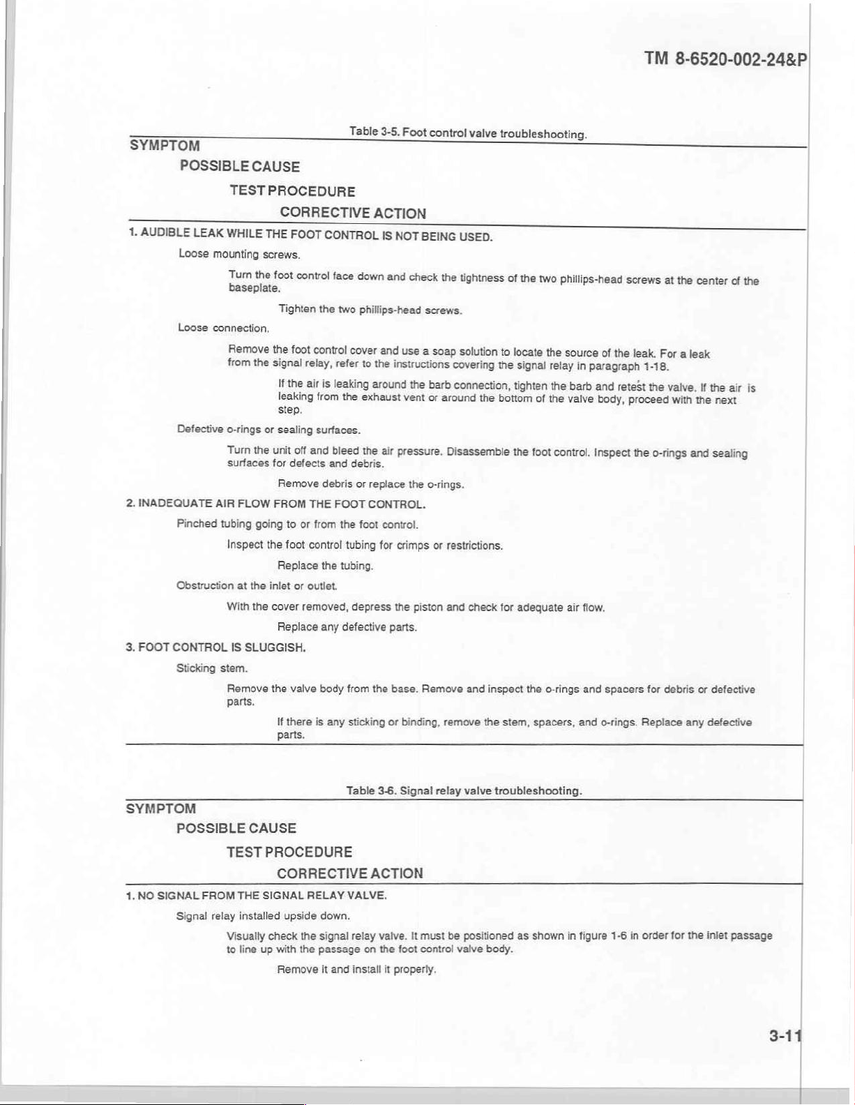
SYMPTOM
1,
AUDIBLE
2.
INADEQUATE
3.
FOOT
POSSIBLE
TEST
LEAK
WHILE
Loose
mounting
to
aseplate.
Loose
connection,
Remove
from
Defective
Pinched
Obstruction
CONTROL
Sticking
o-rings
Turn
surfaces
AIR
FLOW
tubing
Inspect
at
With
IS
stem.
Remove
parts.
CAUSE
PROCEDURE
CORRECTIVE
THE
FOOT
screws.
the
foot
control
Tighten
the
foot
the
signal
relay,
If
the
leaking
step.
or
sealing
the
unit
off
for
defects
Remove
FROM
going
to
or
the
foot
Replace
the
inlet
or
the
cover
removed,
Replace
SLUGGISH.
the
valve
If
there
parts.
Table
CONTROL
face
down
the
two
phillips-head
control
cover
refer
to
air
is
leaking
from
the
exhaust
surfaces.
and
bleed
the
and
debris.
debris
or
replace
THE
FOOT
CONTROL.
from
the
foot
control
tubing
the
tubing.
outlet.
depress
any
defective
body
from
is
any
sticking
3-5.
Foot
ACTION
IS
NOT
BEING
and
check
screws.
and
use
the
around
for
the
a
instructions
the
vent
air
pressure,
the
o-rings.
control.
crimps
the
piston
parts.
base.
Remove
or
binding,
control
valve
troubleshooting.
USED.
the
tightness
soap
solution
covering
barb
connection,
or
around
the
the
bottom
Disassemble
or
restrictions.
and
check
and inspect
remove
the
of
the
two
to
locate
signal
tighten
of
the
foot
for
adequate
the
stem,
spacers,
phillips-head
the
source
relay
in
paragraph
the
barb
the
o-rings
and
valve
body,
control.
inspect
air
flow.
and
and
o-rings.
screws
of
the
retest
proceed
spacers
TM
8-6520-002-24&P
at
the
center
leak.
For
aleak
1-18.
the
valve.
If
the
with
the
next
the
o-rings
and
sealing
for
debris
or
defective
Replace
any
defective
of
the
air
is
|
SYMPTOM
1.
NO
SIGNAL
POSSIBLE
TEST
FROM
Signal
relay
Visually
to
CAUSE
PROCEDURE
CORRECTIVE
THE
SIGNAL
installed
check
line
up
with
Remove
RELAY
upside
down.
the
signal relay
the
passage
it
Table
VALVE.
and
install
3-6.
Signal
ACTION
valve.
on
the
foot
it
properly.
relay
It
must
be
control
valve
valve
troubleshooting.
positioned
as
shown
body.
in
figure
1-6
in
order
for
the
inlet
|
|
passage
Page 29

TM
8-6520-002-24&P
SYMPTOM
POSSIBLE
TEST
2.
3.
4.
Defective
AIR
SIGNAL
The
The
AUDIBLE
AIR
Improper
Signal
AUDIBLE
AIR
Improper
Signal
or
Remove
the
FROM
stem
return
Remove
valve
stem
Disassemble
LEAK
seating
Use a soap
relay
If
Inspect
LEAK
seating
Depress
relay
While
CAUSE
PROCEDURE
CORRECTIVE
improperly
diaphragm
THE
is
WHILE
inlet
the
leak
WHILE
exhaust
the
installed
the
signal
must
Replace
SIGNAL
spring
is
the
hex
If
the
stuck
in
the
Replace
THE
of
the
diaphragm.
solution
If
the
replace
seal
does
is
from
the
stem,
Replace
THE
of
the
diaphragm.
the
foot
If
the
If
the
seal
foot
control
Tighten
the
exhaust
missing.
spring
the
leak
leaking
leak
does
Table
3-6.
diaphragm.
relay
from
aligned
be
any
defective
RELAY
DOES
plug
from
the
is
missing
open
position.
signal
relay
any
defective
UNIT
IS
NOT
to
locate
is
at
the
the
diaphragm.
not
fully
close,
the
exhaust
o-rings,
UNIT
control
and seats
any
defective
IS IN
USE.
until
increases
persists,
not
fully
is
depressed,
the
barb
or
seal
area
Signal
relay
valve
ACTION
the
foot
control
passages
the
with
parts.
NOT
SHUT
end
of
the
signal
or
defective,
valve
and
inspect
parts.
IN
USE.
the
source
of
the leak.
diaphragm
holes,
the
replace
close.
the
for
line,
shut
the
for
debris
parts.
relay
is
actuated.
with
pressure
the
diaphragm.
check
for
sleeve
as
debris
or
necessary
troubleshooting - continued.
and
check
for
the
in
OFF.
relay
valve
replace
it.
all
parts
tighten
the
unit
off,
then
or
defects.
While
on
the
leaks
from
defects.
to
Replace
defects,
valve
and
for
defects,
signal
remove
listening
foot
control,
the
exhaust
stop
debris,
bodies.
verify
debris,
relay
mounting
the
to
the
tighten
holes
the leak.
any
defective
or
improper
that
the
spring
or
improper
screws.
signal
relay
leak,
depress
the
signal
in
the
If
air
comes
parts.
installation.
is
in
place.
installation.
If
leaking
from
the
foot
the
foot
control
relay
mounting
signal relay
from
the
body.
exhaust
The
holes
persists,
control.
all
the
way.
screws.
holes,
inspect
in
SYMPTOM
POSSIBLE
1.
AIR
LEAKS
Improper
CAUSE
TEST
PAST
THE
positioning
Loosen
Table
3-7.
PROCEDURE
CORRECTIVE
VALVE
WHEN
TURNED
of
the
microvalve
the set
screw
in
Tighten
the set
Chip
blower
ACTION
in
the
mount,
screw
valve
OFF.
its
mount.
and
and
lock
(two-way
move
the
microvalve
the
valve
in
microvalve)
troubleshooting.
out
slightly
position.
while
listening
for
continued
leaks.
Page 30
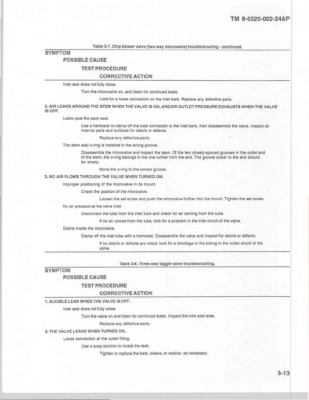
SYMPTOM
POSSIBLE
2.
IS
3.
AIR
OFF.
NO
Inlet
LEAKS
Leaks
The
AIR
FLOWS
Improper
No
Debris
TEST
seal
does
Turn
AROUND
past
the
Use a hemostat
internal
stem
seal
Disassemble
of
the
be
THROUGH
positioning
Check
air
pressure
Disconnect
inside
Clamp
Table
3-7.
CAUSE
PROCEDURE
CORRECTIVE
not
fully
close.
the
microvalve
Look
for a loose
THE
STEM
stem
seal.
parts
and
Replace
o-ring
is
installed
the
stem,
the
Move
THE
of
position
Loosen
the
valve
the
If
no
the
If
no
valve.
o-ring
the
VALVE
the
tube
air
inlet
debris
empty.
the
at
the
microvalve.
off
Chip
blower
ACTION
on,
and
listen
connection
WHEN
THE
VALVE
to
clamp
off
surfaces
any
microvalve
o-ring
microvalve
of
the
inlet.
from
comes
tube
the
for
defective
in
the
wrong
and
belongs
to
the
WHEN
in its
the
microvalve.
set
screw
the
from
with a hemostat.
or
defects
valve
(two-way
for
IS
tube
debris
or
parts.
groove.
inspect
in
the
one
correct
TURNED
mount.
and
push
inlet
barb
the
tube, look
are
noted,
microvalve)
continued
on
the
inlet
ON,
AND/OR
connected
defects.
the
stem.
further
groove.
ON.
the
microvalve
and
check
for a problem
Disassemble
look
troubleshooting
leaks.
barb.
Replace
OUTLET
to
the
inlet
barb,
Of
the
for
two
the
end.
further
air
coming
the
in
valve
from
for a blockage
any defective
PRESSURE
then
disassemble
closely-spaced
The
groove
closer
into
the
mount.
from
the tube.
the
inlet
circuit
and inspect
in
the
tubing
TM
8-6520-002-24&P
-
continued.
parts.
EXHAUSTS WHEN
the
valve.
grooves
of
for
in
to
the
Tighten
the
valve.
debris
the
outlet
in
the
end
the
or
defects.
circuit
set
THE
Inspect
outlet
should
screw.
of
the
VALVE
all
end
SYMPTOM
POSSIBLE
1,
AUDIBLE
Inlet
2.
THE
VALVE
Loose
LEAK
seal
LEAKS
connection
CAUSE
TEST
PROCEDURE
WHEN
THE
does
not
Tum
the
WHEN
Use a soap
CORRECTIVE
VALVE
IS
fully
close.
valve
on
and
Replace
at
Tighten
TURNED
the
outlet
solution
any
or
Table
3-8.
ACTION
OFF.
listen
for
defective
ON.
fitting.
to
locate
the
replace
the
Three-way
continued
parts.
leak.
barb,
leaks.
sleeve,
toggle
valve
Inspect
or
washer,
troubleshooting.
the
inlet
seal area.
as
necessary.
|
|
Page 31

TM
8-6520-002-24&P
SYMPTOM
POSSIBLE
3.
VALVE
Exhaust
DOES
The exhaust
4,
LOOSE
TOGGLE.
The
toggle
Table
CAUSE
TEST
PROCEDURE
CORRECTIVE
seal
does
not
fully
Clamp
off
the
exhaust
NOT
EXHAUST
seal
tube
seal
area
Replace
WHEN
o-ring
is
With a hemostat,
grooves
groove
Inspect
in
should
pin
is
part
the
place.
near
the
Move
way
pin
If
the
If
the
be
the
and
toggle
pin
3-8.
Three-way
ACTION
close,
connected
for
defects
or
any
defective
TURNED
installed
in
clamp
off
head
of
the
the
the
stem,
empty.
o-ring
to
the
out.
the
valve
pin
is
loose,
still in
work
is
toggle
to
the
inlet
debris.
parts.
OFF,
wrong
tube
connected
the
correct
mounting
place,
it
into
valve
troubleshooting - continued.
with a hemostat.
groove
on
the
to
The
the
the
seal
outer
hole
and
in
install
exhaust
groove.
nut.
place
Disassemble
stem.
inlet.
Disassemble
o-ring
belongs
nut
should
the
toggle
is
the
mounting
the
valve.
the
the
one
the
nut
valve.
toggle
so
in
cover
worn. A new
Inspect
Of
the
closer
to
pin
holes
toggle
should
it
covers
the
all
parts
in
the
two
closely-spaced
the
head.
The
other
to
keep
the
be
installed.
toggle
pin
holes.
pin
SYMPTOM
POSSIBLE
TEST
1.
NO
FLOW
THROUGH
Obstruction
Verify
tube.
2,
LEAKS
AROUND
3.
FLOW
Defective
CONTROL
Stripped
o-ring
Use a hemostat
parts
threads
Use a hemostat
parts
CAUSE
PROCEDURE
THE
in
the
barb
that
there
THE
STEM.
seal
and
CANNOT
on
and
CORRECTIVE
NEEDLE
Remove
around
surfaces
Replace
BE
VALVE.
or
valve body.
is a flow
debris.
the
stem.
to
clamp
for
defects
any defective
ADJUSTED.
stem.
to
surfaces
Replace
clamp
for
debris
any defective
Table
ACTION
at
the
off
the
and
off
the
or
3-9,
Needle
valve
inlet.
tube
connected
debris.
parts.
tube
connected
defects.
parts.
valve
Turn
troubleshooting.
the
control
knob
to
the
inlet
bard.
to
the
inlet
bard.
counterclockwise
Disassemble
Disassemble
the
the
to
open
valve.
valve.
the
valve.
Inspect
Inspect
Clamp
all
internal
all
internal
the
inlet
3-14
Page 32

SYMPTOM
1.
LOW
AIR
2.
HIGH
POSSIBLE
PRESSURE.
‘Clogged
Leaking
Leaking
Leaking
PRESSURE.
Leaking
CAUSE
TEST
PROCEDURE
CORRECTIVE
air
filter
disk.
Follow
the
testing
Clean
purge
valve.
Depress
filter
Check
regulator
Use a soap
the
Clean
bowl.
to
assure
Tighten
housing.
Tighten
inlet
seal,
Observe
pressure
Replace
procedure
and
purge
valve
debris
that
the
solution
the
rising
the
Table
ACTION
in
paragraph
reinstall
the
several
from
the
the
bowl
is
bowl
and
to
locate
the
regulator
when
the
inlet
seat
3-10.
Air
regulator
3-15.
air
filter
disk
times
to
reseat
valve
and
check
screwed
check
cover.
for
source
If
unit
is
tightly
continued
of
the leak.
the
not
assembly.
troubleshooting.
following
leak persists,
in
the
for
onto
use.
the
procedures
valve.
continued
the
regulator.
leaks.
If
replace
leaks.
the
in
If
the
leak
persists,
the
diaphragm.
paragraph
leak
persists,
replace
TM
8-6520-002-24&P
3-15.
replace
the
valve
the o-ring.
core.
|
|
|
c.
Amechanical
3-13.
This
subseguent
3-14.
General.
section
of
repair
Water
a.
Testing.
(1)
Remove
(2)
Connect
(8)
Fill
(4)
Depress a syringe
The
b.
Removal,
Vent
(1)
the
manual
or
filter.
the top
the
the
tank
maximum
repair
water
the
schematic
is
Section
contains
replacement
(Refer
of
the
air
supply
of
the
unit
air
water
or
replacement,
by
tank
provided
VII.
MAINTENANCE
procedures
of
RX
or
to
figure
unit.
to
the
unit.
with
water.
button
and
pressure
and
depressing
in
figure
3-1
for
for
the
repair
new
items.
E-1.)
observe
drop
installation.
the
the
NOTE
should
syringe
be
detailed
of
air
pressure
less
button
air
troubleshooting
INSTRUCTIONS
defective
than
to
assemblies
drop.
10
psi.
relieve
pressure.
the
and
failure
or
components
analysis.
and
the
3-1
Page 33

TM
8-6520-002-24&P
AIR
SALIVA
EJECTOR
KV.
CHECK
VAL!
MINI-FILTER
fa
AIR
VACUUM
Fog
AVS
&
—
HANDPIECE
TUBING
7
ASSY
NEEDLE
DISCONNECT
VALVES
QUICK-
WAY
es
TOGGLE
AUTOMATIC
HANDPIECE
HOLDERS
WATER
REGULATOR
GAUGES
AIR
REGULATOR
<
FILTER-
"=
<
AIRIN
MAN
LD
Figure
3-1.
Mechanical
AIR
WATER
VACUUM
schematic.
>
B
>>
z
CONTROL
|
|
|
e
~
ューーーー
CHECK
SYRINGE
CONTROLASSY
GAUGE
VALVE
Page 34

(2)
Remove
(3)
Separate
(4)
Clean
(5)
Dry
the
(6)
Clean
(7)
Install
(8)
Reassemble
(8)
Replace
(10)
Connect
the
the
disk
the
an
the
two
the
filter
disk
with
using
o-ring
o-ring
the
two
the
air
screws
and
using a small
o-ring
screws.
supply,
holding
housing
isopropyl
the
AVS
inspect
and
pressurize
and
handpiece.
filter
the
remove
alcohol
it
for
damage
amount
disk
filter
housing
the
or
replace
of
lubricant.
into
the
the
water
filter
disk.
it
or
wear.
filter
tank,
together.
as
required.
housing.
and
repeat
the
preceding
TM
8-6520-002-24&P
test.
|
|
3-15.
a.
b.
3-16.
Air
filter.
Testing.
(1)
Remove
(2)
Connect
(8)
Fill
the
(4)
Depress a syringe
The
Removal,
(1)
Disconnect
(2)
Depress
(3)
Unscrew
(4)
Install a replacement
(5)
Connect
The
it
should
Water
(Refer
the top
the
air
tank
of
maximum
repair
or
the
the
syringe
the
bowl
the
air
air
filter
be
regulator.
to
of
the
unit.
supply
the
replacement,
air
supply,
also
released
unit
with
water
air
pressure
supply
air
from
filter
serves
to
button
the
pressurize
by
(Refer
figure
the
unit.
water.
button
and
drop
should
and
installation.
to
the
unit.
to
vent
air
filter
and
and replace
the
as a moisture
pressing
to
E-2.)
observe
NOTE
be
the
water
then
the
filter
water
NOTE
separator.
the
purge
figure
the
water
less
than
tank.
unscrew
bowl.
tank,
and
valve.
3-1.)
pressure
15
the
repeat
When
psi.
filter
element.
the
water
drop.
preceding
accumulates
test.
in
the
|
|
|
bowl,
The
water
regulator
by
tightening
sure
are
indications
3-17.
economical
replacement
Master
a.
The water
(1)
Disconnect
(2)
Vent
(3)
Remove
(4)
Remove
(5)
Move
the
coolant
to
replace
valve
the
the
is a not a repairable
fittings
or
replacing
of
internal
block
than
is
not
the
water
the
knobs
the
two
assembly backward
leaks
assembly.
control
readily
to
air
supply
tank
screws
(cartridge
repair.
available.
by
depressing
from
that
the
which
Use
to
the
the
air
assembly.
nylon
washers. Leaks around
require
(Refer
valve)
the
following
unit.
the
and
water
secure
to
the
allow
An external
replacement
to
and
the
air
procedures
syringe
access
air
coolant
master
to
block
leak
around
of
the
figures
coolant
button
the
flow
controls.
assembly
valves.
flow
to
to
relieve
the
inlet
the
adjusting
regulator.
3-2
and
control
remove,
to
the
the
(needle
repair,
or
outlet
knob
or
E-3.)
valve)
and
reinstall
pressure.
faceplate.
can
be
erratic
water
are
normally
the
corrected
pres-
more
valves
if
a
3-17
|
|
Page 35

TM
8-6520-002-24&P
Ensure
(6)
Loosen
(7)
Pull
the
that
the set
valve
out
all
air
screw
of
pressure
on the
the
assembly.
has
been
bottom
of
the
CAUTION
bled
from
assembly
the
dental
that
locks
unit.
each
valve
in
place.
|
RETAINING
STEM
WATER
COOLANT
DRIVE \ ENEEE
SIGNAL
INLET
CROSS-SECTION
RING
REAR VIEW
VIEW
osent
SYRINGE
AIR
SYRINGE
WATER
EXHAUSTSEAL
OUTLET
OUTLET
3-18
CHIP
ト
BLOWER
OS
o?
=
INLET
WATER
068
INLET
Figure
3-2.
Go
\
AIR
COOLANTINLET
Master
block
:
REGULATED
assembly.
o
INLET
AIR
Page 36

b.
2-1a.
If
you
(8)
Inspect
(9)
Disassemble
(10)
Reassemble
(11)
Lightly
(12)
Push
Ensure
(13)
Tighten
(14)
Move
Replace
(15)
Test
the
can't
pull
the
valve
the
the
coat
the
the
valve
that
the
the
set
the
assembly
valve.
the
individual
valves
the
valve
for
wear
valve
by
valve.
o-rings
into
the
toggle
screw
on the
forward
or
with
your
or
damage.
following
with
silicone
assembly
is
properly
bottom
and
the
master
hands,
the
breakout
grease.
block
oriented
of
the
replace
block
NOTE
use
illustration
until
it
is
NOTE
relative
assembly
the
two
screws
assembly
pliers
on
fully
seated.
to
the
block.
by
following
the
(fig
"ON"
to
secure
valve
toggle
3-2)
and
and
the
the
procedures
TM
or
repair
"OFF"
positions.
assembly
8-6520-002-24&P
the
stem.
as
required.
block
to
the
faceplate.
contained
in
paragraph
3-18.
This
microvalve,
be
serviced
valve
and
3-19.
The
chip
sidered a consumable
from
the
3-20.
This
valve
stem,
and
3-21.
a.
Microvalve.
used
in
(if a replacement
extracting
Chip
blower
actuator
Toggle
is
serviced
spring.
The
installed
Syringe.
Button
(1)
Push
(2)
Remove
the
blower
valve
and
valve.
After
toggle can
or
tip
leaks.
the
retainer
the
(two-way
extracting
by
to
(Refer
(Refer
the
automatic
valve
stem
and
valve.
microvalve)
item.
It
can
the
(Refer
removing
inspecting
be
installed
match
the
to
pin
completely
faulty
button
to
figure
handpiece
is
not
readily
spring
to
(Refer
be
serviced
stem
and
to
figure
the
toggle
and
replacing
in
any
lettering
on
figure
out
assembly.
E-5.)
holders,
available)
replace
is a subassembly
the
to
figure
(if a replacement
spring
pin
from
worn
of
four
the
faceplate
is
by
o-rings.
to
replace
E-8.)
the
neck
or
damaged
NOTE
different
E-10.)
of
the
syringe
normally
removing
E-7.)
of
the foot
valve
the
of
the
o-rings,
positions.
of
the
unit.
head
using a paper
considered a consumable
the
valve
from
the
control
is
not
o-rings.
valve
valve.
readily
body
reassemble
Ensure
available)
and
that the
clip
It
is
removing
the
or
other
item.
automatic
normally
by
removing
the
toggle,
valve.
toggle
is
similar
It
can
holder
con-
it
device.
spring
A
that
this
removed.
located
is
spring
inside
does
not
the
fall
out
syringe
and
get
CAUTION
underneath
head
misplaced
the
while
button
you
have
assembly.
the
bution
careful
Be
assembly
Page 37

TM
8-6520-002-24&P
(3)
Apply a light
assembly.
(4)
Install
(5)
While
coating
the
replacement
firmly
holding
of
silicone
assembly.
down
both
lubricant
buttons,
around
reinsert
the
CAUTION
the
outside
retainer
of
pin.
the
o-rings
on a replacement
button
Damage
while
b.
Syringe
(1)
(2)
(3)
(4)
(5)
(6)
(7)
(8)
c.
Leak
tip
Loosen
Remove
Remove
Remove
Apply a light
Reinstall
Install a syringe
Tighten
between
This
button
(1)
Remove
(2)
Remove
(3)
Remove
(4)
Apply a light
(5)
(6)
d.
Syringe
(1)
(2)
Reassemble
Test
the
handle
Turn
the
Disconnect
system.
(3)
Unscrew
(4)
Remove
(5)
Use a pointed
(6)
Apply a light
(7)
Reinstall
(8)
Activate
to
the
inserting
leak.
the
tip
nut.
the
tip.
the
nut.
the
o-ring
coat
the
nut,
the
tip
nut.
air
and
problem
is
depressed.
the nut
the
insert
the
o-ring
coat
the
syringe.
leak.
water
pressure
the
the
syringe
the
connector
instrument
coat
the
connector
the
unit
o-rings
the
retainer
inside
of
silicone
but
do
not
tip
and
ensure
water
is
indicated
and
tip
as
from
the
by
using a pointed
of
silicone
insert,
nut,
toggle
air
supply
handle.
tubes.
of
silicone
tubes
and
test
or
the
brass
spool
pin.
the nut
passages.
and
lubricant
tighten
that
it.
it
is
by a momentary
explained
syringe
lubricant
and
and
to
remove
lubricant
and syringe
the
syringe.
in
head
tip.
to
the
"OFF"
depress
the
can
occur
the
o-ring
around
to
new
o-rings
firmly
seated.
NOTE
spray
the
preceding
using a 5/32
instrument.
to a new
to
o-ring,
position.
both
syringe
o-rings.
the
new
handle.
o-rings,
if
the
two
the
insert
and
carefully
of
water
from a syringe
instructions.
inch
hex
then
install
buttons
then
buttons
are
using a pointed
install
them.
tip
wrench.
it
in
the
insert
to
relieve
install
the
them
not
depressed
when
seat.
pressure
on the
instrument.
the
air
from
the
connector
lines.
dental
3-22.
a.
Button
(1)
(2)
3-20
AVS
replacement.
Remove
Pull
the
handpiece
the
button
button
from
assembly.
retainer
the
screw.
handpiece.
(Refer
to
figure
E-11.)
o
=
Page 38

b.
(1)
(2)
(8)
(4)
(5)
(6)
(8)
Use
Install
(4)
(5)
Replace
Test
(6)
replacement.
Tube
The
Turn
Separate
Unscrew
Remove
If
the
or
Slip
the
Push
the
special
new
the
the
button
handpiece.
the
AVS
air
off
the
air
the
the
the
air
flexible
deformed
terminal
one end
tool
to
spring.
and
supply
supply
flexible
terminal
supply
drain
tubing.
nuts
of
the
tubing
drain
tubing
remove
retainer
tube
is
to
the
tube
nuts
and
tubing.
is
onto
the
onto
the
screw.
inside
AVS
oral
from
retain
to
be
new
the
spring.
the
flexible
evacuator.
the
handpiece
them
NOTE
reused,
air
supply
tubing
NOTE
drain
for
reuse.
trim
the
tubing.
adapter
tube.
and
ends
and
from
the
slightly
then
tighten
tubing
to
remove
the
TM
adapter
any
terminal
8-6520-002-24&P
at
the
other
end.
damaged
nut.
(7)
Feed
adapter
point
handpiece.
3-23.
(8)
where
(9)
(10)
a.
Jet
(1)
(2)
(8)
(4)
as
Lay
Connect
Air
assembly
Close
Remove
Remove
Pull
Do
not
loose
the
far
as
it
the
the
drain
Turn
on
saliva
the
out
the
Verify
control.
flow
tighten
from
the
air
supply
will
go.
tubing
in a straight
tubing
the
air
the
air
ejector.
(venturi)
saliva
the
cap
the
slotted
venturi.
air
that
the
terminal
terminal.
tubing
ends.
Cut
supply
tube
supply
and
(Refer
replacement.
ejector
from
the
screw.
reaching
is
flow
nut
excessively
through
line
without
the
air
to
the
check
control.
saliva
ejector
saliva
the
NOTE
the
flexible
stretching
supply
handpiece
for
to
tubing
leaks.
figure
body.
NOTE
ejector
or
the
tubing
drain
tubing.
or
one
and
tighten
If
no
leaks
E-13.)
momentarily
by
will
slip
out
Then,
push
compressing
inch
short
of
the
terminal
occur,
push
opening
of
the
it.
Mark
that
nut.
the
the
nut
and
drain
the
mark.
flexible
saliva
the
come
tubing onto
air
supply
drain
tubing
ejector
the
tube
onto
tubing
at
the
the
(5)
(6)
(7)
Saliva
b.
a
Insert
Replace
the
Test
ejector
replacement
slotted
the
assembly.
tubing
replacement.
venturi.
and
screw
the
saliva
ejector
cap.
3-21
Page 39

TM
8-6520-002-24&P
(1)
Close
(2)
Remove
(3)
Pull
the
(4)
Remove
(5)
Insert
(6)
Test the
the
saliva
the
hose
tubing
the strain
the
adapter
assembly.
ejector
adapter
from
the
relief
into
flow
control.
fastening
adapter.
spring
the
tubing
and
and
the
tubing
install
it
connect
to
the
saliva
ejector
on a replacement
it
to
the
saliva
body.
tube.
ejector
body.
Section
3-24.
This
syringes
console.
assemblies
casters
open-end
Preparation
section
a.
contains
Storage
(1)
Drain
(2)
Disconnect
(3)
Clean
(4)
Purge
(5)
Perform
(6)
Remove
along
(7)
Pull
the
(8)
Loosen
from
(9)
Push
(10)
Fasten
(11)
Loosen
(12)
If
applicable,
into
the
(13)
Remove
wrench
(14)
Fasten
(15)
Pack
(16)
Pack
(17) Coil
(18)
Position
procedures.
the
the
the
the
the
water
the
the
solid
strainers.
the
air
from
all
applicable
the
syringes
sides
of
AVS
oral
the
thumb
their
slots
foot
control
the
foot
the
thumbscrews
remove
accessory
the
cap
from
the
the
frame
all
accessory
the
post
assembly,
air
supply
the
foam
VIII.
STORAGE
for
storage
procedures
from
the
unit,
air
supply
the
the
evacuator
and
control
kit.
screw
accessory
base
to
unit.
PMCS
from
console.
screws
reinstall
tubing
to
the
that
to
the
kit
items
waste
tubing
insert
and
or
for
preparing
syringes,
the
unit.
procedures.
their
hangers
and
ASE
that
secure
them
up
into
the
unit
using
securing
casters
and
by
secures
kit.
underside
into
their
container,
lay
it
carefully
AND
shipment.
the
dental
and
tubing.
and
push
tubings
upside
the
the
using a 5/32
the
in
back
the
instrument
down
unit.
the elastic
frame
assembly
post
of
the
console
case.
and
the
bottom
place
the
SHIPMENT
unit
for
them
back
into
the
unit.
hanger
inside
the
cord
attached under
to
the
inch
hex
assembly
accessory
of
unit
by
the
into
to
using
kit
case.
the
PROCEDURES
storage
console.
wrench.
the
and
through
Coil the
bar
console.
Install
base
the
cap screw
into
the
case.
shipment
the
bottom
tubes
around
assemblies
the
console.
Lift
the
console
the
foot
of
the
frame
from
dental
unit
within a case.
of
the
unit.
the
inside
to
the
unit.
from
the
pads
and
by
using a 3/4
the
preceding
case.
Lay
of
Lift
frame.
pack
inch
step.
the
the
the
the
(19)
(20)
(21)
Shipment
b.
for
commercial
3-22
The
front
of
Place
the
manuals
Place
the
foam
Close
the
air
procedures.
transportation.
the
console
pad
relief
valve.
No
into
the
over
special
must
tray
the
unit
shipment
face
on
top
and
NOTE
the
side
of
the
install
procedures
of
the
unit.
the
cover
case
of
required
are
with
the
the
air
case.
for
relief
movements.
unit
valve.
Crating
required
is
Page 40

TM
8-6520-002-24&P
DIRECT
4-1.
Overview.
This
chapter
maintenance
4-2.
Support
Specified
DS
4-3.
There
components
and
GS
General.
are
no
provides
personnel.
maintenance
specific
for
maintenance
or
troubleshooting
SUPPORT
Section
maintenance
The
procedures
assembles
units.
Section
CHAPTER
AND
MAINTENANCE
I.
GENERAL
that
is
beyond
in
this
services.
identified
procedures
in
II.
the
chapter
TROUBLESHOOTING
should
appendix
at
these
4
GENERAL
INFORMATION
capability,
B,
levels
capacity,
not
be
section
Il,
of
maintenance.
attempted
are
SUPPORT
and
authorization
at
the
only
authorized
unit
for
level.
for
servicing
unit
level
by
4-1
Page 41

TM
8-6520-002-24&P
A-1.
Army
AR
40-61
AR710-2
AR725-50
AR
750-1
АВ 750-43
A-2.
Technical
TM-DPSC-6500-RPL
A-3.
Technical
TB
38-750-2
TB
43-180
TB
740-10/DLAM
TB750-8-1
regulations.
manual.
bulletins.
4155.5/AFR
67-43
APPENDIX
REFERENCES
Medical
Supply
Reguisitioning,
Army
Test,
Medical
Maintenance
Calibration and
Materiel
Quality
Supplies
Maintenance
(Medical
Logistics
Policy
Materiel
Measurement,
Materiel:
Control,
Only)
Policies
Below
Receipt, and
Maintenance
Medical
Management
Repair
Depot Storage
Expenditure
A
and
Procedures
the
Wholesale
Issue
Policy
and
Diagnostic
Repair
Procedures
Requirements
Limits
Level
System
and
Retail
Equipment
Parts
Reference
for
for
the
Standards,
for
Medical
Maintenance
Program
List
Medical
Appendix
Equipment
Maintenance
Materiel:
Operations
of
M,
Medical
FSC
Army
Groups
A-4.
A-5.
Field
FM
21-11
Supply
$B 700-20
SB708-48
A-6.
Other
(These
SGMMA-M,
publications
Operating
Operation
manual.
bulletins.
publications.
be
may
Frederick,
and
and
MD
Maintenance
Maintenance
obtained
21702-5001.)
from
Instructions,
Instructions,
First
Aid
for
Army
Adopted/Other
Reportable
Cataloging
(CAGE)
Commander,
Sections
Porta-Cart
ADEC
Soldiers
Items
Handbook
À &
Army
U.S.
3408,
Syringes,
Items
H4/H8,
В
Medical
ADEC
ADEC
Selected
Corporation
Corporation
for
Commercial
Materiel
Authorization/List
Government
and
Agency,
ATTN:
of
Entity
Page 42

TM
8-6520-002-248Ρ
B-1.
maintenance
end
be
Section
particular
B-2.
to
each
disassembly
group.
indicates
Various
General.
a.
This
section
levels.
b.
Section
item
consistent
c.
Section
d.
Section
Explanation
a.
Group Number,
b.
Assembly
©.
Maintenance
maintenance
C - Operator
Ο - Unit
Ε - Direct
H - General
D - Depot
Il
or
component.
with
III
Il.
maintenance
assembly.
seguence
the
lowest
maintenance
MAINTENANCE
provides a general
designates
the
lists
IV
contains
The
Group,
Functions,
maintenance
levels
or
support
support
maintenance
overall
The
implementation
assigned
the
tools
and
supplemental
function.
of
columns
Column
beginning
1.
applicable
Column
Column
are
as
crew
maintenance
maintenance
responsibility
maintenance
The
with
2.
This
level
follows:
APPENDIX
Section
explanation
of
levels.
test
equipment
instructions,
in
assembly
assembly
the
3.
groups
first
assembly
column
This
column
authorized
ALLOCATION
I.
INTRODUCTION
of
all
maintenance
for
the
performance
the
maintenance
required
explanatory
section
group
number
are
removed
contains a brief
lists
to
perform
functions
for
each
II.
(Group
listed
in
description
the
various
these
B
and
of
maintenance
maintenance
notes,
No.)
the
maintenance
in a top
maintenance
functions,
CHART
repair
upon
and/or
column
down
disassembly
of
the
The
functions
the
function
is a numerical
components
symbol
authorized
functions
end
item
as
u
illustrations
allocation
functions
designations
at
on the
or
referenced
seguence.
of
(A
identified
component
reguired
group
assigned
chart
(MAC)
each
assembly
through
various
will
from
for a
in
K)
an
for
the
|
The
maintenance
A - Inspect.
characteristics
В - Test.
C-
Service.
elements,
-
Adjust.
D
E - Align.
F - Calibrate. To
in
precise
known
the
shelters.
accuracy,
certified
G-
Install.
with
To
verify
To
such
as
To
To
measurement.
standard.
To
functions
To
determine
established
serviceability
clean,
to
painting
rectify
to
adjust
specified
determine
Consists
to
detect
set
for
use
are
defined
serviceability
standards.
and
preserve,
and
the
and
in
an
to
lubricating,
extent
necessary
variable
the
corrections
of
the
adjust
any
operational
as
follows:
of
to
detect
charge,
be
defined
elements
to
comparison
discrepancy
environment
an
item
by
electrical
and
to
add
separately,
to
bring
into
of
an
item
be
made
of
two
in
comparing
or
mechanical
lubricants,
they
proper
in
the
instruments,
the
such
operating
to
bring
readings
accuracy
as
tents
its
physical,
failure by
cooling
may
it
agents,
be
so
range.
to
optimum
of
instruments
one
of
of
the
instrument
or
International
mechanical,
use
of
test
and
listed.
performance.
or
which
is a certified
being
Standards
equipment.
air.
If
itis
test
equipment
compared
and
electrical
desired
standard
Organization
that
used
o!
with
|
|
|
Page 43

TM
8-6520-002-24&P
H - Replace.
| - Repair.
correction
work
restore
J-
Overhaul.
in
process
an
of
publications
K - Rebuild.
possible
required
d.
to
by
Tools
equipment
e.
Remarks,
maintenance
B-3.
Explanation
a.
Reference
b.
Maintenance
equipment.
c.
Nomenclature,
d.
National
tools
or
test
To
replace
Those
material
damage
Normally
consistent
item
to
completely
for
each
item
The
highest
new
condition
operational
and
Equipment,
(sec
III)
required
Column
functions.
Code,
Level,
Column
Stock
Number,
equipment.
unserviceable
maintenance
operations
to a specific
the
highest
with
quality
serviceable
of
equipment.
degree
in
accordance
considerations
Column
to
perform
5.
This
column
of
columns
Column
7.
Column
3.
This
This
2.
Column
items
failure.
degree
and
economy
Overhaul
of
material
with
or
other
4.
This
the
maintenance
is
provided
in
column
This
column
4.
This
with
serviceable
necessary
Repair
of
maintenance
of
condition
normally
maintenance.
original
manufacturing
paramount
column
for
section
correlates
column
identifies
identifies
column
like
to
restore
may
be
accomplished
performed
operation.
as
prescribed
does
not
It
consists
factors
is
provided
and
functions.
referencing
by
Ill.
to
section
the
maintenance
the
tools
and
provides
the
items.
an
item
to
at
by
the
It
consists
by a maintenance
return
standards.
then
for
code,
II,
test
national
of
that
an
item
of
restoring
Rebuild
only
at
referencing
the
remarks
column
4.
equipment.
stock
serviceable
each
level
Army
in
order
maintenance
standard
to
like
new
equipment
is
performed
the
depot
by
code,
(sec
levels
using
number
condition
of
maintenance.
to
minimize
necessary
in
condition.
as
maintenance
the
tools
IV)
pertinent
the
tools
(NSN)
of
the
through
time
technical
nearly
only
when
level.
and
test
to
the
and
test
specific
to
as
B-4.
Explanation
a.
Reference
b.
Remarks,
maintenance
Code,
Column
function
of
Column
2.
in
section
columns
1.
This
This
column
II.
in
section
column
correlates
provides
IV.
to
section
supplemental
II,
column
information
or
5.
explanatory
notes
pertinent
to
the
Page 44

TM
8-6520-002-24&P
GROUP
NO.
00
01
011
012
013
(1)
Section
(2)
ASSEMBLY
GROUP
Dental
Unit
Air
System
Hose,
Supply
Air
Regulator/Filter
Manifold
Assembly
II.
MAINTENANCE
MAINTENANCE
A
B C
ololo
1.5
[0.5 | 0.6
olo
0.1
[0.2
o o
06
o
0.8
FOR
DENTAL
D
E
ALLOCATION
UNIT
(3) (4)
FUNCTIONS
F
G
H
I
o
10
o
0.2
0.6
[1.1
olo
0.6
[0.8
CHART
J
XK | EQUPMENT
F|
D|01,02,03
8.0 | 9.0
01,02
TOOLS
AND
(5)
REMARKS
CODEA
014
015 | Valve,
016
017
018 | Toggle
019 | Control
02
021
022
Gauge
Check
Master
Assembly
Needle
Water
Tank
Filter
Block
Valve
Valve
Block
System
o 이 이
02
o o
02 03
o
0.3
o
03
o
03
『
1.0}1.4)
olo
0.4/0.3
o
14
0.6 | 0.8 | 2.0
olo
06/08
20
01,02
이
이
『
CODEA
B-3
Page 45

TM
8-6520-002-24&P
(1)
GROUP
NO.
023
024
025
03
031 | AVS
Regulator
Quick-disconnect
Air
ASSEMBLY
Gauge
Vacuum
Assembly
(2)
GROUP
Section
System
Il.
A B
MAINTENANCE
FOR
DENTAL
(3)
MAINTENANCE
C
D
E F
o o
0.5
o
0.4
FUNCTIONS
G H
ALLOCATION
UNIT
I
J
XK J EQUPVENT
08
o
0.3
olo
02102
ojo
11/14
CHART
(4)
TOOLS
AND
01,02
|
(5)
REMARKS
CODE
A
032 | AVS
03
|
04
041
Handpiece
Waste
Air
Saliva
Jet
Assembly
Container
042 ASE
05
051 | Valve
052
Handpiece
Foot
Control
Assembly
Relay,
Signal o
Ejector
o o
0.4
o o
0.2
o
0.4
o
0.4
03
02
olo
0.6
olo
0.8/1.1
olo
0.6
15
o
12
{0.6
|0.8
01,02
01,02
CODEA
CODEA
Page 46

TM
8-6520-002-24&P
GROUP
NO.
06
061
062
07
08
(1)
Section
(2)
ASSEMBLY
GROUP
Accessories
Syringe
Напаресе
Automatic
Handpiece
Frame
Assembly
Holder
II.
MAINTENANCE
MAINTENANCE
C
o
03
o
0.2
o
0.2
FOR
DENTAL
D
E
ALLOCATION
UNIT
(3)
FUNCTIONS
F
G H
olo
0.8
olo
0.5
O| O| F
0.4
I
J
1.0
|0.7
|1.0 |1.0
CHART
K
|EQUPMEN
01,02,03
D
0.7
01,02
01,02
(4
TOOLS
AND
|
(5)
REMARKS
CODEA
CODEA
09
Сазе
О
2.0
|
01,02
CODEA
Page 47

TM
8-6520-002-24&P
REFERENCE
CODE
(1)
01
02
03
Section
(2)
MAINTENANCE
LEVEL
O,F,H,D
O,F,H,D
FH
III.
TOOLS
AND
FOR
DENTAL
NOMENCLATURE
Tool
Kit,
Medical
Maintenance
Repairmans
Tool
Kit,
Medical
Maintenance
Organizational
Shop
Eguipment,
Maintenance:
Maintenance
TEST
UNIT
G)
and
and
Depot
EQUIPMENT
Equipment
Repair:
Equipment
Repair:
Medical
(MEDSOM)
(4)
NATIONAL
STOCK
NUMBER
5180-00-611-7923
5180-00-61
4940-00-594-6455
1-7924
$
Page 48

TM
8-6520-002-24&P
REFERENCE
CODE
4)
A
Tools
and
test
equipment
Section
DENTAL
are
listed
IV.
REMARKS
FOR
REMARKS
for
UNIT
(2)
each
assembly
group.
Page 49

TM
8-6520-002-24&P
COMPONENTS
C-1.
Scope.
This
appendix
items
required
C-2.
The
packaged
it
operation,
operation
requisition
General.
Components
a.
Section
is
issued
b.
Section
for
or
to
and
basic issue
lists
components
for
safe
and
efficient
of
End
Item
II.
Components
transportation
transferred
Ill.
Basic
operate
whenever
between
Issue
it,
and
it
items,
or
to
is
OF
Section
of
end
item
operation.
and
Basic
Issue
of
End
Item.
shipment.
Items.
perform
transferred
based
As
property
These
emergency
between
on
MTOE
APPENDIX
END
ITEMS
and
Items
These
part
of
accounts.
are
the
authorization
ITEM
LIST
|.
INTRODUCTION
basic issue
lists
are
items
are part
the
end
item,
minimum
repairs.
property
Basic
accounts.
C
AND
items
for
the
divided
essential items
of
of
these
issue
the
into
the
This
end
end
items
items
item.
BASIC
equipment
the
following sections.
item, but
must
required
must
manual
to
help
are
removed
be with the
to
place
be
with
is
your
ISSUE
you
inventory
and
end
item
the
equipment
the
equipment
authority
to
separately
whenever
in
during
request
or
C-3.
The
to
These
Explanation
following
a.
Item
b.
National
c.
Description,
identify
code
operational
equipment.
and
in
parentheses
d.
Unit
abbreviations
e.
Quantity,
provides
Number,
Stock
locate
of
Measure,
or
maintenance
Column
of
an
Column
Number,
Column
the item.
followed
Column
are
listed
5.
columns.
explanation
1.
This
column
Column
3.
This
column
The
last line
by the part
4.
This
function.
in
This
This
the
glossary.
column
of
columns
indicates
2.
This
indicates
for
each
number.
column
measure
indicates
found
column
the
item
indicates
is
the
in
both
the
item
indicates
federal
indicates
the
expressed
quantity
listings:
number
the
item
unit
(QTY)
assigned
national
name
and,
the
commercial
of
measure
by a two-character
of
the
to
the
item.
stock
number
if
required, a minimum
and
used
item(s)
assigned
government
in
performing
alphabetical
to
be
used
with
to
the item.
description
entity
(CAGE)
the
actual
abbreviation.
or
on
the
C-1
Page 50

TM
8-6520-002-24&P
(1)
ITEM
NUMBER NUMBER
4
2
3
NATIONAL
Section
6520-00-138-2308
6520-00-103-2858
(2)
Il.
COMPONENTS
STOCK
FOR
DENTAL
Tray
(51840)
Handpiece,
(57078)
Handpiece,
wiChip
(25692)
OF
END
UNIT
(3)
DESCRIPTION
043-003-00
Dental,
57506/3055
Dental,
Blower
53874
Low
High
ITEM
Speed
Speed
UNIT
MEAS
EA
EA
(4)
OF
URE
(5)
QTY
1
1
1
C-2
Page 51

TM
8-6520-002-24&P
(1)
ITEM
NUMBER
+
2
3
4
5
NATIONAL
NUMBER
Section
(2) (3) (4)
STOCK
III.
BASIC
FOR
DENTAL
Operation
Instructions
(51840)
Kit,
(51840)
Operation
Instructions
Case,
(61840)
Pad,
(51840)
ISSUE
UNIT
DESCRIPTION
and
85-0634-01
Accessory
36-0089-00
and
(Syringes)
Carrying
36-0700-00
Foam
Not
Available
ITEMS
Maintenance
Maintenance
UNIT
OF
MEASURE
EA
KT
EA
EA
EA
(5)
QTY
2
1
2
1
1
C-3
Page 52

TM
8-6520-002-24&P
EXPENDABLE
D-1.
This
ment.
D-2.
explanation
to
part
operational
These
equipment.
Scope.
appendix
This
listing
Explanation
a.
Item
Number,
b.
Level,
c.
National
d.
Description,
identify
and
number.
e.
Unit
abbreviations
f.
Quantity,
lists
expendable
is
authorization
Column
of
the
alphabetical
Stock
Column
locate
of
Measure,
or
maintenance
Column
of
columns.
Column
2.
Number,
the item.
are
1.
This
column
4.
Column
function.
listed
6.
This
Section
and
durable
to
requisition
The
item
identifies
character
Column
This
column
The
last line
5.
This
This
in
the
glossary.
column
APPENDIX
AND
DURABLE
MATERIALS
I.
INTRODUCTION
supplies
number
is
provided
3.
This
indicates
for
each
column
measure
indicates
and
and
retain the
(Item
the
lowest
column
the
item
indicates
is
the
materials
No.)
in
appendix
indicates
federal
indicates
expressed
quantity
D
LIST
items
is
sequentially
level
of
B,
the
item
the
the
unit
(QTY)
SUPPLIES
that
are
required
if
not
otherwise
assigned.
maintenance
section | of
national
name
CAGE
of
by a two-character
stock
and,
code
measure
of
the
to
authorized.
that
requires
this
manual.
number
if
required, a minimum
in
parentheses
used
item(s)
to
AND
maintain
in
alphabetical
be
the
the
listed
assigned
followed
performing
abbreviation.
used
with
equip-
item.
An
to
the
item.
description
by the
the
actual
or
on
the
Page 53

TM
8-6520-002-24&P
Section
(1)
ITEM | LEVEL
NO.
1
2
3
4
5
6
7
Il.
EXPENDABLE
(2)
o
o
o
o
o
o
o
AND
(3)
NATIONAL
NUMBER
7920-01-004-7847
6520-01-169-0257
6850-00-110-4498
7920-00-543-7148
7930-00-926-5171
8030-00-889-3534
6505-00-655-8366
STOCK
DURABLE
LIST
DENTAL
Cloth,
(97327)
Lubricant,
(17925)
Cleaning
(81348)
Brush,
(81348)
Polish,
(81348)
Tape,
(81349)
Alcohol,
(1DZ38)
SUPPLIES
FOR
UNIT
DESCRIPTION
Cleaning
Rymple
Silicone
616SY0001
Compound
PD680
Dusting
HB00190
Stainless
P-C-1121
Teflon,
3/10
MIL-T-27730
Isopropyl
Not
Available
AND
(4) (5)
Cloth
301
Spray
Steel
in
MATERIALS
UNIT
OF
MEASURE
RO
EA
PT
í
EA
PT
RO
PT
(6)
QTY
1
1
1
1
1
1
1
D-2
Page 54

TM
8-6520-002-24&P
REPAIR
E-1.
Scope.
This
manual
ment
required
It
authorizes
E-2.
The
Repair
a.
and
item
b.
authorized
E-3.
a.
is
shown.
illustration.
b.
c.
indicates
d.
operational
e.
illustrated
lists
the
General.
Parts
Repair
Special
Illustration,
National
Description,
Parts,
number
for
Explanation
(1)
Figure
(2)
Item
the
CAGE
Unit
of
or
Quantity,
component,
spare
and
for
the
performance
requisitioning
and Special
Section
sequence.
Tools,
Test,
and
the
performance
of
Column
Number.
Number.
Stock
Column
Measure,
maintenance
Column
1.
This
'
This
Number,
code
in
Column
5.
assembly,
PARTS
Section
repair
parts,
of
unit
and
issue
Tools
List
II. A list
3.
function. This
This
of
repair
Support
of
Equipment,
maintenance.
columns
column
column
Column
This
parentheses
indicates
indicates
2.
column
4.
This
column
module,
APPENDIX
AND
I.
INTRODUCTION
special
of
is
followed
indicates
tools,
level,
direct
spare and
divided
This
indicates
column
measure
or
parts
authorized
in
section
the
the
column
end
item.
into
by
indicates
Section
figure
item
the
the
is
expressed
the
E
SPECIAL
special
support,
repair
the
indicates
quantity
The
test
general
parts
following
for
the
III. A list
Il.
number
number
the
federal
item
part
number.
the
unit
by a two-character
(QTY)
abbreviation
equipment;
in
sections:
performance
of
(Fig
(Item
TOOLS
and
support,
consonance
special
national
name
of
tools,
No.)
of
No.)
used
stock
of
the
measure
of
the
item(s)
"AR"
indicates
LIST
other
special
and
depot
level
maintenance.
with
the
MAC
(app
of
maintenance
test,
the illustration
to
identify
number
item.
The
used
in
alphabetical
to
"as
in
and
support
on
each
assigned
last line
performing
be
used
required.”
support
figure
which
abbreviation.
with
equip-
B).
number
equipment
the
item
on the
to
the item.
for
each
the
actual
or
on the
item
item
E-4.
Explanation
a.
Item
Number,
b.
Level,
explanation
c.
National
d.
Description,
to
identify
part
operational
equipment.
and
number.
e.
Unit
Quantity,
f.
of
Column
Column
of
the
alphabetical
Stock
Column
locate
the
Measure,
maintenance
or
Column
of
2.
This
Number,
4.
item.
Column
function.
This
6.
columns
1.
This
number
column
This
The
identifies
character
Column
column
last
line
5.
This
This
column
3.
in
section
is
seguentially
the
is
provided
This
column
indicates
for
each
column
measure
indicates
indicates
lowest
in
appendix
indicates
the
federal
item
indicates
expressed
is
quantity
the
III.
assigned.
level
of
maintenance
B,
the
item
the
the
unit
by
(QTY)
section | of
national
name
CAGE
of
measure
two-character
a
of
stock
and,
code
the
this
if
item(s)
that
reguires
manual.
number
required, a minimum
in
parentheses
used
alphabetical
to
the
assigned
in
performing
used
be
listed
followed
abbreviation.
with
item.
An
to
the item.
description
by the
the
actual
the
on
or
Page 55

TM
8-6520-002-24&P
E-2
Figure
E-1.
Water
filter.
Page 56

TM
8-6520-002-24&P
FIG
NO.
EA
E-1
(D
ILLUSTRATION
E-1
E-1
ITEM
NO.
1
2
3
4
Section
NATIONAL
6520-01-295-7504
5330-01-297-4158
(2)
STOCK
NUMBER
II.
REPAIR
FOR
DENTAL
Housing
(61840)
Screw,
(51840)
Filter,
(51840)
Packing,
(61840)
PARTS
UNIT
DESCRIPTION
19-0110-00
4-40
by
001-047-00
Disk
19-0220-00
Preformed
030-016-00
(3)
1/4
in,
LIST
Zinc
Plated
(4)
UNIT
MEAS
EA
EA
EA
EA
(5)
QTY
OF
URE
2
2
1
1
E-3
Page 57

TM
8-6520-002-24&P
19
18
E-4
Figure
E-2.
Air
filter
and
regulator.
Page 58

TM
8-6520-002-24&P
ILLUSTRATION
E-2
Ε-2
E-2
(1)
FIG | ITEM
NO. NO.
E-2
E-2
E-2
E-2
1
2
3
4
5
6
了
NATIONAL
NUMBER
Section
(2)
STOCK
II.
REPAIR
FOR
DENTAL
Screw,
(51840)
Locknut
(51840)
Spring
(51840)
Spring,
(51840)
Cover
(51840)
Diaphragm
(51840)
Body,Valve
(51840)
PARTS
UNIT
(3)
DESCRIPTION
Adjusting
Not
Available
006-006-00
Cap
Not
Available
Compression
Not
Available
Not
Available
Assembly
97-0200-00
Not
Available
LIST
(4) (5)
UNIT
OF
MEASURE
EA
EA
EA
EA
EA
EA
EA
QTY
1
1
1
1
1
1
1
E-2
E-2
E-2
E2
E-2 12
E-2
E-2
E-2
E2
E-2
E2
8
9
10
11
13
14
15
16
17
18
5330-01-295-3215
4310-01-295-3244
Packing,
(51840)
Poppet
(51840)
Spring,
(51840)
Assembly,
(51840)
Filter
(51840)
Filter
(51840)
Bowl,
(51840)
Valve
(51840)
Quick-disconnect,
(51849)
Tubing,
(51840)
Elbow,
(51840)
Preformed
030-023-00
97-0240-00
Compression
Not
Available
Inlet
Seat
Not
Available
Element,
Element,
Sediment
Core,
1/4
Intake
97-0280-00
Retainer
Not
Available
97-0290-00
Dental
026-033-00
026-040-00
Braided,
024-088-00
by
in
022-003-00
Male,
3/8
1/8
Air
in
in
od
mpt
Cleaner
in
3/8
od
EA
EA
EA
EA
EA
EA
EA
EA
EA
EA
EA
1
1
1
1
1
1
1
1
1
1
1
E-5/E-6
blank
Page 59

TM
8-6520-002-24&P
(1)
ILLUSTRATION
FIG
No. | No.
E-2
E2
E2
E-2
E-2
ITEM
19
20
21
*
=
Section
(2) (3)
NATIONAL
NUMBER
6520-01-300-4550
II.
STOCK
REPAIR
FOR
DENTAL
PARTS
UNIT
DESCRIPTION
Elbow,
(61840)
Plug,
(51840)
Screw,
(61840)
Service
(51840)
Air
(51840)
3/8
in
022-025-00
1/8
in
mpt,
021-020-00
Button
001-012-00
Kit,
Air
90-0030-00
Filter/Regulator
026-041-00
LIST
by
1/8
in
mpt
Socket
Head,
Filter/Regulator
Head,
6-32
by 1/4
Brass
in.
(4)
UNIT
OF
MESURE
EA
EA
EA
KT
EA
(5)
QTY
1
1
2
AR
1
*
Includes
**
Includes
items
6,
9,
12,
items 1 through
and
15.
15
and
item
21.
E-7
Page 60

TM
8-6520-002-24&P
NEEDLE
VALVE
CARTRIDGE
FRONT
VIEW
E-8
Figure
E-3.
Master
block
CARTRIDGE
VALVE
assembly.
Page 61

TM
8-6520-002-24&P
ILLUSTRATION
E-3
(1)
FIG | ITEM
NO.
E-3
E-3
E-3
E3
E3
E-3
ES
E-3
E-3
NO.
1
2
3
4
5
6
7
8
9
10
Section
NATIONAL
5315-01-297-4198
5360-01-246-1988
4820-01-247-4962
(2) (3)
STOCK
PEER
II.
REPAIR
FOR
DENTAL
Set
Screw,
Cup
(51840)
Packing,
(51840)
Packing,
(61840)
Pin,
Straight,
(51840)
Body,
(51840)
Spring,
(51840)
Packing,
(1840)
Stem,
(51840)
Toggle,
(61840)
Knob
(51840)
PARTS
UNIT
DESCRIPTION
Socket,
Point,
Stainless
007-001-00
Preformed
030-008-00
Preformed
030-010-00
Headless
011-039-00
Valve
33-0099-00
Compression
22-0040-00
Preformed
030-001-00
Cartridge
29-0840-00
Plastic
22-0462-00
027-018-00
6-32
Valve
LIST
by
1/8
in,
UNIT
MEAS
EA
EA
EA
EA
EA
(4)
OF
URE
EA
EA
EA
EA
EA
(5)
QTY
1
1
4
1
1
1
1
1
1
1
E3
E-3
E3
E-3
E-3
E-3
E-3
11
12
13
14
15
16
17
Ring,
Retaining,
(61840)
Stem,
Cartridge,
(51840)
Packing,
(51840)
Valve
Body,
(51840)
Packing,
(51840)
Packing,
(61840)
Screw,
(61840)
010-017-00
33-0103-00
Preformed
030-004-00
33-0102-00
Preformed
030-010-00
030-008-00
Adjusting
29-0100-00
Internal
Needle
Preformed
Valve
EA
EA
EA
EA
EA
EA
EA
E-9/E-10 blank
1
1
1
1
1
1
1
Page 62

TM
8-6520-002-24&P
ILLUSTRATION
(1)
FIG | ITEM
NO.
E3
E-3
E-3
E-3
ЕЗ
NO.
18
.
=.
....
Section
NATIONAL
NUMBER
6520-01-296-7429
Il.
DENTAL
(2)
STOCK
REPAIR
FOR
Packing,
(61840)
Service
(51840)
Master
(51840)
Valve,
(61840)
Valve,
(51840)
PARTS
UNIT
DESCRIPTION
Preformed
030-004-00
Cartridge,
Kit,
90-0308-00
Block
38-0185-00
Needle
33-0101-00
Cartridge
33-0100-00
LIST
G)
Needle
Cartridge
Valve
(4
UNIT
OF
MEASURE
EA
KT
EA
EA
EA
(5)
QTY
1
AR
AR
AR
AR
Includes
*
Includes
**
Includes
***
Includes
****
items
items
items
items
3,
2,
through
1
through
10
through
2
15,
13,
11,
18.
16.
9.
16,
and
18.
E-11
Page 63

TM
8-6520-002-24&P
Figure
E-12
E-4.
Control
block
assembly.
Page 64

TM
8-6520-002-24&P
(1)
ILLUSTRATION
FIG | ITEM
NO.
E-4
E-4
E-4
E-4
Е-4
E4
E4
E-4
E-4
NO.
1
2
3
4
5
6
7
8
9
NATIONAL
DEEE
Section
(2) (3)
STOCK
II.
REPAIR
FOR
DENTAL
Screw,
(51840)
Cap,
(51840)
Diaphragm
(51840)
Stem,
(61840)
Packing,
(61840)
Spring
(51840)
Control
(51840)
Diaphragm,
(51849)
Cover,
(61840)
PARTS
UNIT
DESCRIPTION
Socket
002-092-00
Water
Valve
38-0181-00
38-0054-00
Control
29-0835-00
Preformed
030-001-00
013-025-00
Block
38-0176-00
Control
38-0179-00
Front
38-0178-00
Head,
Block
LIST
4-40
Block
by 1/4
in
(4)
UNIT
OF
MEASURE
EA
EA
EA
EA
EA
EA
EA
EA
EA
(5)
QTY
2
1
1
1
1
1
1
1
1
Es
Е-4
E-4
E-4
E-4
E4
E-4
E4
10
11
12
13
14
15
16
*
6520-01-296-7429
*
Includes
items
1 1
3,
4,
5, 8,
Packing,
(51840)
Screw,
(51849)
Packing,
(51840)
Stem,
(51840)
Knob
(51840)
Screw,
(61840)
Gasket
(51840)
Service
(51840)
10,
12,
and
Preformed
030-004-00
Adjusting
29-0100-00
Preformed
030-004-00
Needle
33-0103-00
027-017-00
Phillips,
002-097-00
38-0186-00
Master
Kit,
90-0308-00
16.
Valve
4-40
by
Block
1/4
in
EA
EA
EA
EA
EA
EA
EA
EA
1
1
1
1
1
2
1
AR
E-13
Page 65

TM
8-6520-002-24&P
E-14
Figure
E-5.
Microvalve.
Page 66

TM
8-6520-002-24&P
(1)
ILLUSTRATION
FIG
NO. NO.
E-5
Es
ES
E-5
ITEM
1
2
3
4
NATIONAL
NUMBER
Section
(2)
STOCK
Il.
REPAIR
FOR
DENTAL
Packing,
(51840)
Stem,
(51840)
Spring,
(51840)
Body,
(51840)
PARTS
UNIT
(3)
DESCRIPTION
Preformed
030-001-00
Needle
Microvalve
Valve
29-0820-00
Helical
29-0190-00
Compression
10-0440-00
LIST
(4)
UNIT
OF
MEASURE
EA
EA
EA
EA
(5)
QTY
2
1
1
1
E-15
Page 67

TM
8-6520-002-24&P
M
ves
V
di
E-16
Figure
E-6.
Automatic
holder.
Page 68

TM
8-6520-002-24&P
@)
ILLUSTRATION
FIG
NO. NO.
E-6
ES
ES
E-6
E-6
E-6
E-6
ITEM
1
2
3
4
5
6
7
NATIONAL
NUMBER
Section
@)
STOCK
II.
REPAIR
FOR
DENTAL
Holder,
(51840)
Actuator,
(51840)
Spring,
(51840)
Clamp,
(61840)
Pin,
(61840)
Screw,
(51840)
Spacer
(51840)
PARTS
UNIT
DESCRIPTION
Automatic
99-0541-00
Automatic
40-0667-00
Helical
40-0182-00
Automatic
40-0710-00
Dowel,
011-041-00
Knurled,
Compression
1/16
001-003-00
40-0665-00
(3)
Block
Holder
Holder
in
od
10-32
LIST
by
0.52
by
1/2
in
in
(4)
UNIT
OF
MEASURE
EA
EA
EA
EA
EA
EA
EA
(5)
QTY
1
1
1
+
2
2
1
E-6
8
Lever,
Lock-Release
(51840)
22-0462-00
EA
1
Page 69

TM
8-6520-002-24&P
valve
E-18
Figure
E-7.
Foot
control
with
chip
blower
valve.
Page 70

TM
8-6520-002-24&P
ILLUSTRATION
E-7
E-7
E-7
E-7
FIG
NO.
E-7
E-7
E-7
E-7
E-7
E-7
E-7
E-7
E-7
E-7
E-7
E-7
E-7
E-7
4)
ITEM
NO.
1
2
3
4
5
6
7
8
9
10
11
12
13
14
15
16
17
18
NATIONAL
NUMBER
Section
(2) (3)
STOCK
II.
REPAIR
FOR
DENTAL
Cover
(51840)
Ring,
(51840)
Spring,
(51840)
Ring,
(51840)
Stem,
(51840)
Spring,
(51840)
Body,
(51840)
Diaphragm,
(51840)
Body,
(51840)
Screw,
(51840)
Spring,
(51840)
Packing,
(51840)
Stem,
(51840)
Packing,
(51840)
Spacer
(51840)
Packing,
(51840)
Screw,
(51840)
Screw,
(51840)
PARTS
UNIT
DESCRIPTION
22-0110-00
Retainer
38-0237-00
Helical
013-011-00
Retaining,
010-002-00
Valve
38-0246-00
Helical
013-022-00
Valve
Valve,
Phillips,
Relay,
Compression
External
Compression
38-0241-00
Valve,
38-0054-00
Relay
38-0056-00
4-40
002-016-00
Helical
10-0440-00
030-001-00
22-0778-00
Socket
Sheet
Compression
Preformed
Foot
Preformed
035-019-00
38-0213-00
Preformed
030-012-00
Head,
002-092-00
Metal,
003-022-00
Flat
Control
LIST
in
7/8
by
by
4-40
Phillips,
1/4
by
6
(4)
UNIT
OF
MEASURE
EA
EA
EA
EA
EA
EA
EA
EA
EA
EA
EA
EA
EA
EA
EA
EA
in
EA
EA
in
1/2
(5)
QTY
1
1
1
1
1
1
1
1
1
2
1
2
1
1
1
1
2
4
E-19/E-20
blank
Page 71

TM
8-6520-002-24&P
ILLUSTRATION
E-7
E-7
FIG
NO.
E-7
E-7
E-7
E-7
ΕΤ
E-7
E-7
E-7
E-7
E-7
E-7
(1)
|
ITEM
NO.
19
20
21
2
23
24
25
26
27
28
>
**
ss
Section
NATIONAL
NUMBER
5330-01-297-4157
6520-01-296-7427
II.
DENTAL
Q)
STOCK
REPAIR
FOR
Screw,
(61840)
Base
(51840)
Microvalve
(51840)
Pedestal
(61840)
Pin,
(51840)
Set
(51840)
Packing,
(51840)
Spring,
(51840)
Button
(61840)
Housing,
(51840)
Bumper,
(51840)
Service
(51840)
Valve,
(51840)
PARTS
UNIT
DESCRIPTION
Sheet
003-031-00
38-0055-00
38-0062-00
38-0072-00
Dowel
011-016-00
Screw,
Socket,
007-002-00
Preformed
035-005-00
Helical
22-0040-00
38-0070-00
Plastic,
38-0046-00
Self-adhesive
017-007-00
Foot
Kit,
90-0312-00
Blower
Chip
38-0078-00
LIST
(3)
Metal,
Phillips, 4 by
6-32
Compression
Holes
Two
Control
by
3/16
1/2
in
MEASURE
in
(4)
UNIT
OF
EA
EA
EA
EA
EA
EA
EA
EA
EA
EA
EA
KT
EA
(5)
QTY
4
1
1
1
1
1
1
1
1
1
9
AR
AR
Indicates
*
Includes
**
***
Includes
parts
items
items
that
5,
3,
21
through
are
8,
6,
illustration.
the
12,
in
14,
and
16.
not
11,
shown
27.
E-21
Page 72

Page 73

TM
8-6520-002-24&P
FIG
NO.
E-8
Е-8
E8
E-8
E-8
4)
ILLUSTRATION
Е-8
E-8
ITEM
NO.
1
2
3
4
5
6
7
Section
NATIONAL
5315-01-295-7196
(2)
STOCK
NUMBER
II.
REPAIR
FOR
DENTAL
Pin,
(51840)
Spring,
(51840)
Stem,
(61840)
Packing,
(51840)
Nut,
(51840)
Toggle,
(61840)
Toggle,
(51840)
Body,
(51840)
Body,
(51840)
Body,
(51840)
PARTS
UNIT
DESCRIPTION
Straight,
Needle
15/32
Valve
Valve
Valve
Headless
011-038-00
Helical
22-0040-00
29-0840-00
030-001-00
006-009-00
Compression
Valve
Preformed
by
3/32
Plastic
22-0462-00
OR
Metal
22-0470-00
33-0006-00
OR
33-0050-00
OR
33-0078-00
(3)
in,
LIST
9/16
in
Hex
(4)
UNIT
OF
MEASURE
EA
EA
EA
EA
EA
EA
EA
EA
EA
EA
(5)
QTY
1
1
1
2
2
1
1
1
1
1
E-23
Page 74

TM
8-6520-002-24&P
E-24
Page 75

TM
8-6520-002-24&P
(D
ILLUSTRATION
FIG
NO. NO.
E-9
E-9
E-9
E-9
E9
ITEM
1
2
3
4
5
Section
(2)
NATIONAL
NUMBER
5355-01-295-7190
STOCK
II.
REPAIR
FOR
DENTAL
Stem,
(51840)
Stem,
(51840)
Packing,
(51840)
Ring,
(51840)
Nut,
Chrome
(61840)
Knob
(51840)
PARTS
UNIT
DESCRIPTION
Needle
Needle
Retaining,
15/32
Valve,
38-0102-00
OR
Valve,
33-0094-00
Preformed
030-010-00
010-013-00
by
3/32
Plated
006-009-00
027-008-00
LIST
(3) (4)
UNIT QTY
OF
MEASURE
Black
White
Internal
in,
9/16
in
Hex,
EA
EA
EA
EA
EA
EA
(5)
1
1
1
1
2
1
E-9
E-9
6
7
Set
Screw,
Point,
Black
(51840)
Body,
(51840)
Body,
(51840)
007-016-00
Valve
33-0086-00
Valve
13-0353-00
Socket,
Oxide
OR
6-32
by
1/8
in,
Cup
EA
EA
EA
1
1
1
E-25
Page 76

TM
8-6520-002-24&P
E-26
Figure
E-i0.
Syringe.
Page 77

TM
8-6520-002-24&P
(4)
ILLUSTRATION
FIO | ITEM
NO.
E-10
E-10
E-10
E-10
E-10
E-10
E-10
E-10
E-10
NO.
1
2
3
4
5
6
7
8
9
Section
(2) (3)
NATIONAL
NUMBER
6520-01-296-7425
STOCK
II.
REPAIR
FOR
DENTAL
Identifier,
(61840)
Identifier,
(61840)
Button
(51840)
(Includes
Button
(51840)
Packing,
(51840)
Spool,
(61840)
Packing,
(51840)
Packing,
(51840)
Ring,
(61840)
PARTS
UNIT
DESCRIPTION
Blue
40-0691-00
Yellow
40-0689-00
Assembly
23-0040-00
items 4 through
Stem
23-0025-00
Preformed
035-010-00
Brass
23-0024-00
Preformed
035-012-00
Preformed
033-006-00
Retaining
010-019-00
LIST
9)
(4)
UNIT
OF
MEASURE
EA
EA
EA
EA
EA
EA
EA
EA
EA
(5)
QTY
1
1
1
2
2
1
2
2
2
E-10
E-10
E-10
E-10
E-10
E-10
E-10
E-10
10
11
12
13
14
15
16
17
6515-01-296-5761
Spring,
(51840)
Pin,
(61840)
Body,
(51840)
Connector,
(61840)
Packing,
(51849)
Terminal,
(51840)
Terminal,
(61840)
Handle,
(51840)
Conical
013-038-00
Dowel
011-029-00
Syringe
23-0093-00
Tubing,
23-0758-00
Preformed
030-004-00
Non-circulating
23-0760-00
Circulating
23-0782-00
Syringe
23-0757-00
Compression
Straight
EA
EA
EA
EA
EA
EA
EA
EA
.
E-27/E-28
2
1
1
2
2
1
1
1
blank
Page 78

TM
8-6520-002-24&P
ILLUSTRATION
|
FIG
NO.
E-10
E-10
E-10
E-10
E-10
E-10
E-10
E-10
E-10
E-10
E-10
E-10
(1)
ITEM
NO.
18
19
20
21
2
23
24
25
2
*
==
e.
Section
(2)
NATIONAL
NUMBER
6520-01-114-9988
6520-01-296-7426
II.
REPAIR
DENTAL
STOCK
FOR
UNIT
Bushing,
(61840)
Packing,
(51840)
Packing,
(51840)
Insert,
(51840)
Packing,
(51840)
Sleeve,
(51840)
Syringe
Nut,
(51840)
Nozzle
(61840)
Sleeve,
(51840)
Service
(51840)
Service
(51840)
Assembly,
(51840)
PARTS
Handle
23-0768-00
Preformed
033-003-00
Preformed
035-020-00
Tip
23-0878-00
Preformed
033-006-00
Swivel,
23-0886-00
23-0875-00
23-0872-00
Non-swivel
23-0887-00
Kit,
90-0317-00
Kit,
90-309-00
23-0094-00
LIST
(3)
DESCRIPTION
Adapter
Metal
Syringe
Button
Syringe
Head
(4)
UNIT
MEAS
EA
EA
EA
EA
EA
EA
EA
EA
EA
KT
KT
EA
(5)
QTY
OF
URE
1
1
1
1
1
1
1
1
1
AR
AR
AR
Includes
*
**
Includes
Includes
***
items
items
items
8,
7,
5,
5,
7, 8,
through
1
20.
and
19,
10,
9,
and
9.
through
19
and
12
26.
E-29
Page 79

TM
8-6520-002-24&P
Page 80

TM
8-6520-002-24&P
ILLUSTRATION
FIG
E-11
E-11
E-11
E-11
E-11
E-11
E-11
E-11
E-11
E-11
NO.
品
ITEM
NO.
1
2
3
4
5
6
7
8
9
10
|
NATIONAL
Section
©
NUMBER
STOCK
II.
REPAIR
FOR
DENTAL
Tubing,
(51840)
Assembly,
(51840)
Nut,
Special
(61840)
Spring,
(51840)
Tubing,
(51840)
Tubing,
(51840)
Screw,
2-56
by
(51840)
Button,
(51840)
Packing,
(51840)
Spring,
(51840)
PARTS
UNIT
©
DESCRIPTION
Gray,
3/4
in
024-004-00
Tubing
10-0170-00
10-0120-00
Strain
013-009-00
0.145
024-003-00
Convolute,
024-093-00
Trusshead,
1/8in
001-002-00
Locking
10-0110-00
Preformed
030-001-00
Helical
10-0440-00
Adapter
Relief
in
od
5/8
Slotted,
Compression
od
LIST
in
id
(4)
UNIT
OF
MEASURE
EA
EA
EA
EA
EA
EA
EA
EA
EA
EA
6)
QTY
1
1
1
1
1
1
1
1
2
1
E-11
E-11
E-11
E-11
11
*
a
+
4720-01-297-8658
*
Includes
**
Includes
***
Includes
items 7 through
items 8 through
items 3 through
AVS
Handpiece
(51840)
Handpiece,
(61840)
AVS
(61840)
AVS
(51840)
Not
10-0700-00
Button
10-0600-00
Tubing
024-039-00
Body
Availabie
AVS
Assembly
Kit
Assembly
10.
10.
6.
EA
EA
KT
EA
1
AR
AR
AR
E-31
Page 81

TM
8-6520-002-24&P
E-32
Figure
E-12.
Air
vacuum
system.
Page 82

TM
8-6520-002-24&P
(1)
ILLUSTRATION
FIG | ITEM
No. | No.
E-12
E-12
E-12
E-12
E-12
E-12
E-12
E-12
E-12
1
2
3
4
5
6
の
8
9
Section
(2)
NATIONAL
NUMBER
4510-00-393-3728
STOCK
II.
REPAIR
FOR
DENTAL
Elbow,
(51840)
Tube,
(51840)
Pin, Roll
(51840)
Baffle,
(51840)
Nut,
(61840)
Packing,
(51840)
Ring,
(51840)
Strainer,
(51840)
Lower
(51840)
PARTS
UNIT
DESCRIPTION
Saliva
Drain
Spiral
Hex,
Retaining,
Body
Ejector
12-0440-00
12-0350-00
011-003-00
12-0380-00
Nylon,
12-0390-00
Preformed
030-018-00
010-0390-00
Waste
10-0310-00
17-0290-00
LIST
(3) (4)
UNIT
OF
MEASURE
Drain
1/2-20
Internal
by
7/16
in
EA
EA
EA
EA
EA
EA
EA
EA
EA
(5)
QTY
1
1
1
1
1
1
1
1
1
E-12
E-12
E-12
E-12
E12
E-12
E-12
E-12
E-12
10
11
12
13
14
15
16
17
E
4310-01-297-8696
Lid,
AVS
Waste
(51840)
Screw,
(51840)
Jar,
(51840)
Stopper,
(51840)
Ring,
(51840)
Filter
(51840)
Housing,
(51840)
Upper
(51840)
Lower
(51840)
17-0320-00
Slotted,
001-048-00
Cylinder
14-0010-00
028-002-00
Retaining,
010-001-00
Element
10-0540-00
10-0530-00
Body
10-0430-00
Body
17-0280-00
Container
10-32
Rubber
Muffler
Assembly,
by 1/4
Internal
AVS
in
EA
EA
EA
EA
EA
EA
EA
EA
EA
E-33/E-34
1
4
1
1
1
1
1
1
AR
blank
Page 83

TM
8-6520-002-24&P
(1)
ILLUSTRATION
FIG
NO.
E-12
ITEM
NO.
se
Section
(2) (3)
NATIONAL
NUMBER
Il.
REPAIR
DENTAL
STOCK
FOR
Waste
(51840)
PARTS
UNIT
Container
17-0270-00
LIST
DESCRIPTION
Assembly,
AVS
(4)
UNIT
OF
MEASURE
EA
(5)
QTY
1
*
Includes
**
Includes
items 7 through
items 7 through
11
and
item
13.
13.
E-35
Page 84

TM
8-6520-002-24&P
Figure
E-13.
Air
saliva
ejector.
E-36
Page 85

TM
8-6520-002-24&P
Section
ILLUSTRATION
E-13
E-13
FIG
NO.
E13
E-13
E-13
E-13
E13
E13
E13
E-13
E43
E-13
E-13
E-13
E-13
E-13
E-13
E-13
(1)
ITEM
|
NO.
1
2
3
4
5
6
7
8
9
10
11
12
13
14
15
16
17
18
NATIONAL
NUMBER
5330-01-297-8635
6520-01-297-1677
5305-01
6520-00-089-4087
-297-8631
(2)
STOCK
Il.
REPAIR
FOR
DENTAL
Screw,
(61840)
Washer,
(61840)
Bracket,
(51840)
Nut,
(51840)
Cap,
(51840)
Packing,
(51840)
Screen
(51840)
Thumbscrew,
(51840)
Screw,
(51840)
Body,
(61840)
Adapter,
(51840)
Spring,
(51840)
Tip,
(51840)
Body
(51840)
Tubing,
(51840)
Screw,
(51840)
Mounting
(51840)
Barb,
(61840)
PARTS
UNIT
DESCRIPTION
Slotted,
001-054-00
Shoulder,
004-020-00
Cover
ASE
36-0051-00
by
6-32
Hex,
006-012-00
ASE
12-0140-00
Preformed
030-031-00
12-0090-00
6-32
001-011-00
Slotted,
001-032-00
ASE
12-0100-00
in
1/8
022-001-00
Relief
Strain
36-0082-00
Ejector
Saliva
12-0183-00
12-0184-00
Ejector,
024-008-00
Slotted,
001-012-00
Bracket
12-0280-00
mpt
in
1/8
023-003-00
(3)
6-32
Nylon
1/4
6-32
mpt
Saliva
6-32
by
LIST
by
3/8
Holder
in
1/4
by
1/8
by
1/4
by
1/4
by
in
1/4
in
in
in
in
od
in
Tubing
(4)
UNIT
OF
MEASURE
EA
EA
EA
EA
EA
EA
EA
EA
EA
EA
EA
EA
EA
EA
FT
EA
EA
EA
5
Dre
1
2
1
1
1
1
1
1
1
1
2
2
1
1
8
2
1
1
E-37/E-38
blank
Page 86

TM
8-6520-002-24&P
(1)
ILLUSTRATION
|
FIG
NO.
E-13
E-13
E-13
E-13
E-13
E-13
E-13
E-13
E-13
E-13
ITEM
NO.
19
20
21
24
=
ea
ARE
A
Section
(2)
NATIONAL
NUMBER
5330-01
5330-01-297-8634
II.
DENTAL
STOCK
-297-8645
REPAIR
FOR
Drain
(61840)
Packing,
(51840)
Packing,
(61840)
Venturi
(51840)
Tube,
(51840)
Ring,
(51840)
Cap
(61840)
Jet
(51840)
ASE
(51840)
Saliva
(51840)
PARTS
UNIT
DESCRIPTION
Pipe
12-0160-00
Preformed
030-01
Preformed
030-012-00
12-0462-00
Threaded
12-0030-00
Retaining,
010-002-00
Assembly
12-0150-00
Assembly
12-0010-00
Assembly
12-0070-00
Ejector
12-0200-00
LIST
(3)
4-00
External
Assembly
Tip
(4)
UNIT
OF
MEASURE
EA
EA
EA
EA
EA
EA
EA
EA
EA
EA
(5)
QTY
1
1
2
1
1
1
AR
AR
AR
AR
through
5
Includes
*
Includes
**
Includes
***
Includes
****
items
items
items
items
through
21
through
5
and
13
8.
24.
through
16
and
11
14.
24.
E-39
Page 87

TM
8-6520-002-24&P
DØ
E
E-40
Figure
E-14.
Water
tank
system.
Page 88

TM
8-6520-002-24&P
ILLUSTRATION
E-14
E-14
E-14
FIG
NO.
E-14
E-14
E-14
E44
E-14
E-14
E-14
E-14
E-14
E-14
4)
|
ITEM
NO.
1
2
3
4
5
6
7
8
9
10
11
È
==
NATIONAL
NUMBER
4820-01
Section
(2) (3)
STOCK
-300-0507
II.
REPAIR
FOR
DENTAL
Vent
Button
(51840)
Packing,
(61840)
Screw,
1/8
(51840)
Spring,
(51840)
Packing,
(51840)
Tank
(61840)
Quick-disconnect,
(61840)
Valve,
Valve,
Truss
in
Helical
Elbow,
(51840)
(51840)
(51840)
Quick-disconnect
(51840)
Plug
(61840)
Water
(61840)
Street,
Toggle,
Check
Assembly,
Tank
PARTS
UNIT
DESCRIPTION
10-0111-00
Preformed
030-001-00
Head,
001-002-00
Compression
22-0040-00
Preformed
030-016-00
36-0039-00
Female,
026-015-00
in
1/8
021-019-00
3-way
33-0048-00
026-073-00
with
026-003-00
Tank
36-0041
36-0023-00
-00
Assembly
LIST
Slotted,
npt
2-56
1/4
1/8
by
Valve,
by
in
in
Male
d
id
fpt
UNIT
MEAS
EA
EA
EA
EA
EA
EA
EA
EA
(4)
OF
EA
EA
EA
EA
EA
(5)
QTY
URE
1
1
1
1
1
1
1
1
1
1
1
AR
AR
*
Includes
Includes
**
items 1 through
items
through
1
5.
8.
E-41
Page 89

TM
8-6520-002-24&P
5
E-42
Figure
E-15.
Frame
assembly.
Page 90

TM
8-6520-002-24&P
FIG
NO.
E-15
E-15
E-15
E-15
E-15
E-15
E-15
E-15
E-15
E-15
E-15
E-15
(1)
|
ILLUSTRATION
E-15
E-15
ITEM
NO.
1
2
3
4
5
6
4
8
9
10
11
12
13
14
NATIONAL
NUMBER
Section
(2)
STOCK
II.
REPAIR
FOR
DENTAL
Thumbscrew,
(51840)
Post,
(51840)
Plate,
(51840)
Knob
(51840)
Post,
(51840)
Side
(51840)
Cap
10-32
(51840)
Foot
(51840)
Cross
.|
(51840)
Cap
1/2-13
(51840)
Clamp
(51840)
Cap
1/2-13
(51840)
Bumper,
(51840)
Nut,
(61840)
PARTS
UNIT
DESCRIPTION
5/16-18
001-099-00
Inner
36-0013-00
Nut
36-0017-00
027-007-00
Outer
36-0009-00
Member,
Screw,
by
Member,
Screw,
by
Bar
Screw,
by 2 1/2in
1/4-20
Frame
36-0003-00
Socket
5/8
in
001-088-00
36-0004-00
Frame
36-0001-00
Hex
31/2in
001-098-00
36-0007-00
Socket
001-090-00
Rubber
017-002-00
3/8
by
006-037-00
(3)
Head,
Head,
Head,
in
LIST
by 3/4
in
(4)
UNIT
OF
MEASURE
EA
EA
EA
EA
EA
EA
EA
EA
EA
EA
EA
EA
EA
EA
(5)
QTY
2
1
1
1
1
2
4
4
1
1
2
2
4
1
Page 91

TM
8-6520-002-24&P
ILLUSTRATION
N/A
N/A
N/A
N/A
N/A
N/A
N/A
N/A
N/A
N/A
(1)
FIG | ITEM
NO.
N/A
N/A
N/A
N/A
N/A
N/A
N/A
N/A
NO.
1
2
3
4
5
6
7
8
9
10
11
12
13
14
15
16
17
18
NATIONAL
AE
5220-01-300-0524
Section
(2)
STOCK
II.
REPAIR
FOR
DENTAL
DESCRIPTION
Funnel,
(51840)
Gauge,
(51840)
Quick-disconnect,
(51840)
Air
(51840)
Cup,
(51840)
Valve,
(51840)
Tip,
(51840)
Handpiece
(51840)
Filter
(61840)
Spool,
(51840)
Syringe
(51840)
Frame
(51840)
Hub,
(51840)
Disk,
(51840)
Housing
(51840)
Bracket,
(51840)
Bezel,
(51840)
Manifold,
(51840)
Plastic, 3 1/4
009-003-00
Comparator,
026-009-00
026-065-00
Vacuum
10-0729-00
Oral,
Dry
11-0450-00
Needle
13-0361-00
Dental
10-0010-00
10-0716-00
19-0100-00
Foot
22-0993-00
23-0088-00
Assembly
36-0015-00
to
Cart
36-0019-00
to
Hub
36-0021-00
36-0030-00
Housing,
36-0032-00
Gauge
36-0025-00
Hex
36-0050-00
PARTS
UNIT
G)
in
Air
Female,
System
Suction
Assembly,
Control
Frame
Cart
Holder
Center
Shape
LIST
od
1/4
AVS
Support
in
(4)
UNIT
OF
MEASURE
EA
EA
id
EA
"
EA
EA
EA
EA
EA
EA
EA
EA
EA
EA
EA
EA
EA
EA
EA
(5)
QTY
1
1
1
1
5
2
3
1
1
2
1
1
1
1
1
1
1
1
E-44
Page 92

TM
8-6520-002-24&P
ILLUSTRATION
N/A
(1)
FIG | ITEM
NO.
N/A
N/A
N/A
N/A
N/A
N/A
NO.
19
20
21
24
25
Section
(2) (3)
NATIONAL
NUMBER
II.
REPAIR
DENTAL
STOCK
FOR
UNIT
Cover
(51840)
Cord,
(51840)
Handle
(51840)
Kit,
Accessory
(51840)
Faceplate
(51840)
Control
(51840)
Foot
Control
(51840)
PARTS
DESCRIPTION
36-0062-00
Shock,
16
36-0072-00
36-0080-00
36-0089-00
36-0103-00
Assembly
38-0191-00
Assembly
38-0251-00
LIST
in
(4)
UNIT
OF
MEASURE
EA
EA
EA
KT
EA
EA
EA
(5)
QTY
1
1
2
1
1
1
1
N/A
N/A
N/A
N/A
N/A
N/A
NA
NIA
N/A
N/A
26
27
31
32
3
34
35
Tubing
Air
(51840)
Tubing
(51840)
Holder,
(51840)
Holder,
(51840)
Gauge
(51840)
Screw,
(51840)
Screw,
(61840)
Cap
(51840)
Cap
(51840)
Washer,
(51840)
3
1/2in
Assembly,
Supply
45-0182-00
Assembly,
98-0448-00
Handpiece,
99-0519-00
Handpiece,
99-0528-00
Water
and
24-0252-00
Round
001-001-00
Slotted,
001-004-00
Screw,
Screw,
Socket
001-009-00
Socket
002-041-00
Flat,
004-005-00
Quick-disconnect,
Handpiece
Universal,
Automatic
Regulator
Slotted,
Head,
3/8
by
10-32
1/4-20
Head,
6-32
Head,
in
3/16
Nylon,
Assembly
10-32
in
id
Black
by
3/8
by
EA
EA
EA
EA
EA
in
in
EA
EA
EA
EA
EA
by
1
1
2
9
1
1
2
20
4
6
42
E-45
Page 93

TM
8-6520-002-24&P
ILLUSTRATION
N/A
N/A
(1)
FIG | ITEM
NO. NO.
N/A
N/A
N/A
N/A
N/A
N/A
N/A
N/A
NA
N/A
N/A
N/A
36
38
40
43
37
3
4
42
44
45
46
47
48
49
NATIONAL
NUMBER
(2)
Section
STOCK
Il.
REPAIR
FOR
DENTAL
Plug,
Hole,
(51840)
Plug,
(51840)
Barb,
(For
(51840)
Barb,
(For
(61840)
Tee,
(For
(51840)
Body,
(51840)
Uni-clamp,
(51840)
Clamp,
(51840)
Clip,
(51840)
Tubing,
1/8
(51840)
Tubing,
1/8
(51840)
Tubing,
Dashes)
(51840)
Tubing,
Dashes)
(51840)
Tubing,
1/4inod
(51840)
018-012-00
Hex
Head,
021-016-00
10-32
1/4
in
023-001-00
10-32
1/8
in
023-004-00
Barbed,
1/8
in
023-014-00
Tee,
024-071-00
025-007-00
Sleeve
025-015-00
Adhesive
025-017-00
Regulated
in
od
036-003-00
Oral
in
od
036-005-00
Signal
036-006-00
Drive
036-010-00
Regulated
036-051-00
PARTS
UNIT
(3)
DESCRIPTION
Plastic,
by
od
by
od
Tubing)
10-32
1/8
1/2
10-32
1/8
in
Tubing)
1/16
in
Tubing)
1/16
in
in
id
Back
Air
Air
(Orange
Air
Water
(Green
Air
Cavity,
LIST
in id
(Yellow),
(Red),
Black
with
Black
with
(Yellow),
(4)
UNIT
OF
MEAS
EA
EA
EA
EA
EA
EA
EA
EA
EA
FT
FT
FT
FT
FT
(5)
QTY
URE
1
6
16
20
2
1
39
19
3
=
e
>
*
S
E-46
Page 94

TM
8-6520-002-24&P
(1)
ILLUSTRATION
FIG
NO.
N/A
ITEM
NO.
50
Section
(2)
NATIONAL
NUMBER
II.
REPAIR
DENTAL
STOCK
FOR
UNIT
Tubing,
(51840)
PARTS
Cold
036-053-00
LIST
(3)
DESCRIPTION
Water
(Blue),
1/4
in
od
(4)
UNIT
OF
MEASURE
FT
6)
QTY
length
Specify
*
the
you
wish
order.
to
E-47/E-48
blank
Page 95

TM
8-6520-002-24&P
Section
(1)
ITEM | LEVEL
NO.
1
2
3
4
5
6
7
8
9
10
11
(2)
o
o
o
o
o
o
o
o
o
o
o
Ill.
SPECIAL
(3) (4)
NATIONAL
NUMBER
6520-01-296-9899
TOOLS,
STOCK
TEST,
FOR
DENTAL
Hemostats
(51840)
Syringe,
(51840)
Gauge,
(51840)
Pliers,
(51840)
Pliers,
(51840)
Magnifier,
(51840)
Tools,
Packing
(61840)
Gauge
(51840)
Barb
Tee
(51840)
Tubing,
(51840)
Tool,
(51840)
AND
UNIT
DESCRIPTION
009-008-00
Test
98-0050-00
Test
024-015-00
Ring
Snap
009-007-00
Tubing
009-014-00
Pocket
009-009-00
Installation
(O-rings)
009-013-00
Kit
023-028-00
and
023-014-00
1/8
024-015-00
Spring
96-0030-00
of
Clamp
ft
2
by
in
Removal
SUPPORT
Preformed
Kit
EQUIPMENT
(5)
UNIT
OF
MEASURE
EA
EA
EA
PR
PR
EA
KT
KT
KT
FT
EA
(6)
QTY
1
1
1
1
1
1
1
1
1
2
1
Page 96

GLOSSARY
TM
8-6520-002-24&P
ADEC
app
ASE
AVS
CAGE
cm
DLAM
DPSC
fig
FM
fpt
ADEC
Corporation.
Air
Force
regulation.
Appendix.
Army
regulation.
Automatic
Air
vacuum
Operator
Commercial
Centimeter.
Depot
Department
Defense
Defense
Direct
Each.
Direct
Figure.
Field
Female
Federal
Foot
General
General
saliva
system.
or
maintenance.
Logistics
Personnel
support.
support
manual.
pipe
stock
(feet).
support.
support
ejector.
crew.
and
government
of
the
Army.
Agency
Support
maintenance.
thread.
class.
maintenance.
entity.
Manual.
Center.
NSN
od
para
Inner
diameter.
Inch.
Kit.
Maintenance
Medical
Male
Modified
Not
Number.
National
Unit
Outer
Paragraph.
supply,
pipe
thread.
table
applicable.
stock
maintenance.
diameter.
allocation
optical,
of
number.
chart.
and
organization
maintenance.
equipment.
and
GLOSSARY-1
Page 97

TM
8-6520-002-24&P
Preventive
Pair.
Pounds
Pint.
Quality
Quality
Quantity.
Roll.
Repair
Reparable
Section.
Supply
Technical
Technical
per
assurance.
control.
parts
bulletin.
bulletin.
manual.
maintenance
square
inch.
list.
exchange.
checks
and
services.
GLOSSARY-2
Page 98

This
index
tified
by
paragraph
is
organized
alphabetically
number.
by
topic
INDEX
and
by
subtopic
within a topic.
TM
Topics
8-6520-002-24&P
and
subtopics
are
iden-
Accessory
Administrative
Air
coolant,
Air
filter,
Air
relief
Air
saliva
Alcohol,
AVS
Basic
Case,
Caution,
Cleaning,
Common
Complaints,
kit,
3-12,
valve,
ejector, 1-16,
2-2,
handpiece
issue
1-13,
2-2, 3-7,
disinfecting,
names,
Components
Coolant
Air,
1-12, 1-16, 1-17, 1-18,
Water,
1-12, 1-16, 1-17,
2-1, 2-2,
storage,
3-7
1-5,
3-24
1-12, 1-16, 1-17, 1-18,
3-15
1-13,
3-7,
3-24
3-23
3-14
assembly,
items,
3-3
3-1, 3-7,
3-17,
1-8
medical
of
end
3-22
3-24
3-21
and
sterilizing
materiel,
item,
3-3
3-7,
1-18,
1-9
3-12,
3-7,
3-7,
3-12-,
procedures,
3-17
3-12,
3-17
3-17
2-2
Deficiencies,
Destruction
reporting,
of
Army
Equipment
Capabilities,
Characteristics,
Chip
blower
Cleaning,
Components,
Control
Control
2-1,
block
functions,
Description,
Differences,
Dimensions,
Disinfectant,
Disinfecting
Durable
supplies,
3-10
materiel,
1-11
1-11,
1-13
valve,
3-12,
2-2,
3-9,
3-12,
1-12, 1-14,
assemblies,
1-16,
3-1
1-12
1-14
1-13
2-2
procedures,
3-4
1-4
3-19
1-16,
1-17,
2-2
3-14,
2-2,
3-1
3-18,
3-7,
3-24
3-12,
3-13
INDEX-1
Page 99

TM
8-6520-002-24&P
Features,
Gauges,
Inspection,
Operation,
1-11
1-16,
2-1,
Schematic,
Servicing,
Shipment,
Shutdown
1-1,
1-6,
procedures,
Specifications,
Start-up
procedures,
Unpacking,
Expendable
Explanation
supplies,
of
Filter
Air,
3-12,3-15
Water,
Forms,
3-14
1-3
Interval
Lubrication,
1-17,
2-1,3-7,3-12
2-2,
3-7,
3-9,
2-3, 2-4,
3-12
1-5,
1-11,
3-7,
3-24
1-13
2-1
3-7
3-4
abbreviations
3-8
3-12, 3-14,
3-7,
3-9
1-12,
2-2, 3-7, 3-9,
2-1
and
terms,
3-17,
1-2
3-20
3-11,
3-18, 3-19,
3-20
PMCS,
Lubrication,
1-5,
2-1, 3-8,
Maintenance
Master
Mechanical
Medical
Microvalve,
Model
Nomenclature
Note,
Official
Operation
Operation
Overview,
Overview,
Preventive
Procedures,
Purpose
Quality
block
assembly,
schematic,
materiel
3-12,
differences,
2-1,
2-2,
nomenclatures,
of
auxiliary
under
unit
support
maintenance
initial
of
equipment,
assurance
2-4,
3-9
3-12
functions,
3-1
1-12,
3-12
complaints,
3-18
1-14
cross-reference,
3-7, 3-8, 3-9,
unusual
level
maintenance,
level
operation,
or
3-15,
1-8
equipment,
conditions,
maintenance,
checks
1-1
quality
1-17,
3-1,
3-17
1-9
1-8
3-17, 3-20, 3-21, 3-22, 3-23,
」
2-3
2-4
3-1
4-1
and
services,
1-5,
2-4, 3-7, 3-9,
2-1,
control,
1-7
3-24
3-10, 3-11,
3-24
INDEX-2
Page 100

TM
8-6520-002-24&P
Records,
Repair
Reports,
Safety,
Scope,
Shipment,
Signal
Special
Sterilizing
1-3,
1-5
parts,
3-5
1-3, 1-9,
care,
and
1-1,3-11
1-6,
3-24
relay
valve,
tools,
3-6,
procedures,
Storage
Administrative,
Preparation,
Syringe,
Tabulated
Test
equipment,
Toggle
Tools,
valve,
3-2,
Troubleshooting
1-6
1-12, 1-16,
data,
1-13
3-12,
3-6,
3-7,
3-7,
3-10
handling,
1-18,
3-12
3-22
2-2
1-5
2-1,
2-2,
3-2
3-20
3-22
1-15
3-7, 3-9,
3-12, 3-14, 3-15,
3-17,
3-21,
3-24
Corrective
General,
Possible
Support
Test
procedure,
Unit
level,
Type
of
manual,
Unit
level
Warranty,
Water
coolant,
Water
filter,
Water
regulator,
action,
3-12
3-12
cause,
level,
3-12
4-3
3-12
3-12
1-1
maintenance,
1-10
1-12,
1-16,1-17,1-18,3-7,3-12,3-17
3-14
3-12,
3-16
3-1
INDEX-3
 Loading...