

Page 1
a'dec
"OPERATION
AND
MAINTENANCE
INSTRUCTIONS
-
PORTA-CART
DENTAL
FIELD
FEDERAL
OPERATING
PORTABLE,
NATIONAL
6520-00-140-7663
ITEM
IDENTIFICATION
AND
AIR
STOCK
TREATMENT
NUMBER
3406
UNIT,
OPERATED
Page 2
A-dec
for
one
warranty
have
are
excluded.)
A-dec
resulting
use,
The
by
excessive
warrants
year
from
is
to
no
other
within
the
from
warranty
NO
OTHER
its
products
time
repair,
or
remedy.
Written
warranty
improper
also
or
misuse.
WARRANTIES
OR
WARRANTY
against
of
installation.
at
its
option,
(All
special,
notice
period.
installation
does
not
OTHERWISE
defects
to
incidental,
of
breach
The
and
cover
AS TO
aYdee
in
material
A-dec's
replace
warranty
upholstery
ARE
sole
the
and
of
warranty
does
maintenance,
damaged
MERCHANTABILITY
MADE.
or
workmanship
obligation
unit.
The
buyer
coincidental
must
be
not
cover
accident
or
under
the
shall
damages
given
to
damage
or
mis-
disfigured
9
o
PUBLICATION PRINTED
NUMBER
85-0634-01
ařdec
2601
Crestview
Newberg,
Phone
Telex
Oregon
(503)
538-7478
4970448
Drive
97132
ADEC
(ITT)
U.S.A
IN
U.S.A.
oh
Page 3
aídec
Porta-Cart
3406
OPERATION
THIS
TO
EQUIPMENT
DEFENSE
NATIONAL
NO
OTHER
FEDERAL
2601
CRESTVIEW
DRIVE * POST
AND
INSFRUCTION
PERSONNEL
STOCK
USE
OF
CONTRACT
OFFICE
MAINTENANCE
MANUAL
PURCHASED
NUMBER
THIS
NUMBERS
BOX
APPLIES
BY
THE
SUPPORT
6520-00-140-7663.
MANUAL
111
+»
CENTER
IS
DLA
DLA
NEWBERG,
INSTRUCTIONS
EXCLUSIVELY
UNITED
UNDER
AUTHORIZED
120-87-C-4625
120-87-C-4649
OREGON
97132 * TELEPHONE
STATES
BY
A-DEC.
(503)
538-7678
Page 4
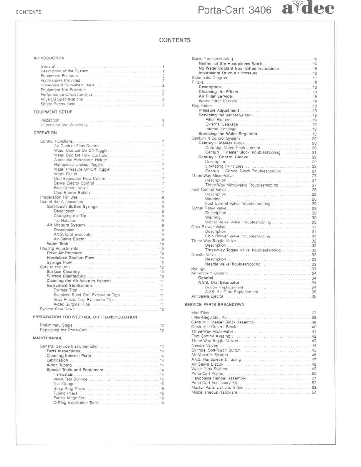
CONTENTS
CONTENTS
Porta-Cart
3406
@idee
INTRODUCTION
General
Description
Equipment
Accessories
Government
Eovipment
Performance
Physical
Safety
EQUIPMENT
버마
Unpaexing
OPERATION
Control
Preparation
Use
Routing
Care
System
PREPARATION
Preliminary
Repacking
MAINTENANCE
General
of
Features
Provided
Furnished
Not
Specifications
Precautions
SETUP
ana
Functions
Air
Coolant
Water
Water
Automatic
Handpiece
Water
Water
Oral
Evacuator
Saliva
Foot
Control
Chip
Blower
For
of
the
Accessories
Soft-Touch
Description
Changing
Tip
Rotation
Air
Vacuum
Description
ANS.
Air
Saliva
Water
Tank
Adjustments
Drive
Air
Handpiece
Syringe
Flow
of
the
Unit
Surface
Cleaning
Surface
Disintecting
Cleaning
Instrument
Parts
Cleaning
Lubrication
A-dec
Special
the
Syringe
Stainless
Gray
Plastic
A-dec
Snut-Down
FOR
Steps
the
Service
Inspections
Internal
Tubing
Tools
Hemostats
Valve
Test
Test
Gauge
Snap
Ring
Tubing
Pocket
O-Ring
ος
the
System
Items
Provided
Characteristics
Assembly
Flow
Coolant
Coolant
Pressure
Outlet
Ejector
Button
Oral
Pressure
Coolant
Surgical
Porta-Cart
Pliers
Magnifier
Installation
Control
On-Off
Toggle
Flow
Handpiece
Use
the
System
Ejector
Sterilization
Tips
Steel
STORAGE
Instrumentation
and
Syringe
Controls
Lockout
Evacuator
Air
Oral
Pliers
Holder
Toggie
On-Off
Toggle
Fiow
Control
Centro!
Vaive
Button
Syringe
Tip
Flow
Vacuum
System
Oral
Evacuator
Evacuator
Tips
OR
Parts
Equipment
Tools
TRANSPORTATION
Tips
Tips
ま
È
2
2
2
2
2
2
3
a
3
ココ
ココ
ココ
ココ
の
gogoogeee
10
Basic
Troubleshooting
Neither
of
the
No
Water
Insufficient
Schematic
Filters
Description
Checking
Air
Filter
Water
Regulators
Pressure
Servicing
Filter
External
Internal
Servicing
Century
Il
Century
Cartridge
Century
Century
Description
Operating
Century
Three-Way
Description
Three-Way
Foot
Contro]
Description
Warning
Foot
Signa!
Relay
Description
Warning
Signal
Chip
Blower
Description
Chip
Three-Way
Description
Three-Way
Needie
Valve
Description
Needle
Syringe
Air
Vacuum
General
AMS.
Button
AMS.
Air
Saliva
SERVICE
PARTS
Min-Fitter
Filter-Reguiator,
Century
II
Century
Il
Three-Way
Foot
Control
Three-Way
Needle
Valves
Syringe,
SoftTouch
Air
Vacuum
ANS.
Hanepiece & Tubing
Air
Saliva
Water
Tank
Porta-Cart
Hanapiece
Porta-Cart
Master
Parts
Miscellaneous
Handpieces
Coolant
Drive
Diagram
the
Filters
Service
Filter
Service
Adjustment
the
Air
Element
Leakage
Leakage
the
Water
Control
System
II
Master
Valve
II
Master
II
Control
Principles
II
Control
Micro-Valve
Micro-Valve
Valve
Control
Valve
Valve
Relay
Valve
Valve
Blower
Valve
Toggle
Valve
Toggle
Valve
System
Oral
Evacuator
Replacement
Air
Tube
Ejector
BREAKDOWN
Air
Master
Block
Control
Block
Micro-Valve
Assembly
Togale
Valves
Button
System
Ejector
System
Frame
Hanger
Assembly
Accessory
List
and
Hardware
Work
from
Either
Air
Regulator
Reguiator
Block
Replacement
Block
Blocks
Block
Valve
Troubleshooting
Replacement
Assembly
Kit
Index
Handpiece.
Pressure
Troubleshooting
Troubleshooting
Troubleshooting
Troubleshooting
Troubleshooting
Troubleshooting
Troubleshooting
16
16
16
16
17
18
A
18
18
18
19
18
19
1
E
19
19
20
20
20
2
22
22
22
24
27
Page 5
a
dy
атаес
INTRODUCTION
GENERAL
The A-dec
the
finest
profession.
of
reliable
amount
sion
instrument,
is
required.
tions
given
the
best
This
manual
troubleshooting,
plus
auxiliary
as
specified
(12-10-79).
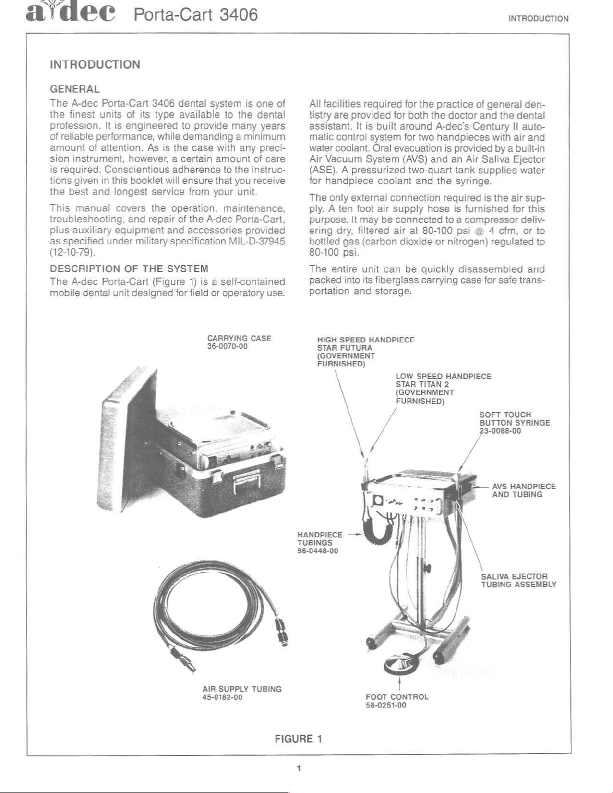
DESCRIPTION
The A-dec
mobile
Porta-Cart
units
It
is
performance,
of
attention.
Conscientious
in
this
and
longest service
covers
equipment
under
Porta-Cart
dental
unit
Porta-Cart
3406
dental
of
its
type
available
engineered
As
however, a certain
booklet
the
and
repair
military
OF
THE
designed
to
provide
while
demanding a minimum
is
the
case
adherence
will
ensure
from your
operation,
of
the
A-dec
and
accessories
specification
SYSTEM
(Figure
1) is a self-contained
for
field
3406
system
or
is
to
the
many
with
any
amount
to
the
instruc-
that
you receive
unit.
maintenance,
Porta-Cart,
provided
MIL-D-37945
operatory
one
of
dental
years
preci-
of
care
use.
All
facilities
tistry
assistant.
matic
water
Air
Vacuum
(ASE). A pressurized
for
handpiece
The
only
ply. A ten
purpose.
ering
bottled
80-100
The
entire
packed
portation
required
are
provided
It
is
control
coolant.
dry,
system
System
external
foot
lt
may
filtered
gas
(carbon
psi.
unit
into
its
and
for
built
around
Oral
evacuation
(AVS)
coolant
connection
air
supply hose
be
connected
air
dioxide
can
fiberglass
storage.
for
the
practice
both
the
A-dec's
for
two
handpieces
and
two-quart
and
the
at
80-100
or
be
quickly
carrying
of
general
doctor
is
required
to a compressor
nitrogen)
and
the
Century
with
provided
an
tank
syringe.
is
furnished
psi @ 4
disassembled
case
Air
Saliva
supplies
is
for
the
regulated
by a built-in
cfm,
safe
INTRODUCTION
den-
dental
II
auto-
air
and
Ejector
water
air
sup-
for
this
deliv-
or
to
to
and
trans-
CARRYING
36-0070-00
CASE
HIGH
SPEED
STAR
FUTURA
(GOVERNMENT
FURNISHED)
\
\
HANDPIECE 一 一
TUBINGS
38-0448-00
HANDPIECE
LOW
SPEED
TITAN
HANDPIECE
2
SOFT
BUTTON
'3-0088-00
AVS
AND
STAR
(GOVERNMENT
FURNISHED)
/
SALIVA
TUBING
TOUCH
SYRINGE
HANDPIECE
TUBING
EJECTOR
ASSEMBLY
AIR
SUPPLY
45-0182-00
TUBING
FIGURE
1
FOOT
58-0251-00
CONTROL
Page 6
INTRODUCTION
Porta-Cart
3406
a'dec
EQUIPMENT
*
Century
Handpieces
*
Air
*
Water
+
Individual
Handpiece
*
Individual
Handpiece
*
Drive
*
Disc
*
Self-Contained
*
Water
+
Air
+
Soft
Il
Automatic
Coolant
Coolant
Water
Drive
Air
Pressure
Type
Foot
Pressure
Vacuum
AVS
Handpiece
Oral
Evacuator
Air
Saliva
Polypropylene Waste
Touch
(23-0088-00)
Quick-Disconnect
Adjustable
Fiberglass
Stainless
ACCESSORIES
s
Two
Coiled
nectors
®
10
Foot
Height
Carrying
Steel
Handpiece
(98-0448-00)
Air
Supply
(45-0182-00)
¢
Water
Tank
e
Stainless
®
Stainless
3
Each
®
Porta-Cart
Steel
Steel
Accessory
FEATURES
Flow
Control
On-Off
Coolant
Air
Pressure
Gauge
Control
Two-Quart
On-Off
System,
Assembly
Flow
Ejector
Button
Filler
Syringe
Water
Frame
Tray,
PROVIDED
Tubing
Funnel
Dry
Oral
Control
Toggle
Flow
Adjustment
with
Chip
Water
Toggle
including:
Control
with
Solids
Bottle
with
Outlet
Case
(36-0070-00)
15
1/8”
x10
Tubings
with
(009-003-00)
Oral
Cup
Evacuator
Kit
(36-0089-00)
System
(17-0270-00)
5/8”
with
Quick
(11-0450-00)
Tips
for
Control
Tank
Separator
Coiled
for
for
Blower
Tubing
(043-003-00)
Midwest
Disconnects
(10-0010-00),
Two
Each
Each
Button
Con-
Oral
Evacuator
Package
AVS
Handpiece
(049-001-01)
PERFORMANCE
The
A-dec
with
1.
High
Procedure
2.
Low
Procedure
3.
Vibration,
cedure
STD-810B.
4.
Shock,
dure
Water
Waste
Air
Supply
Gas
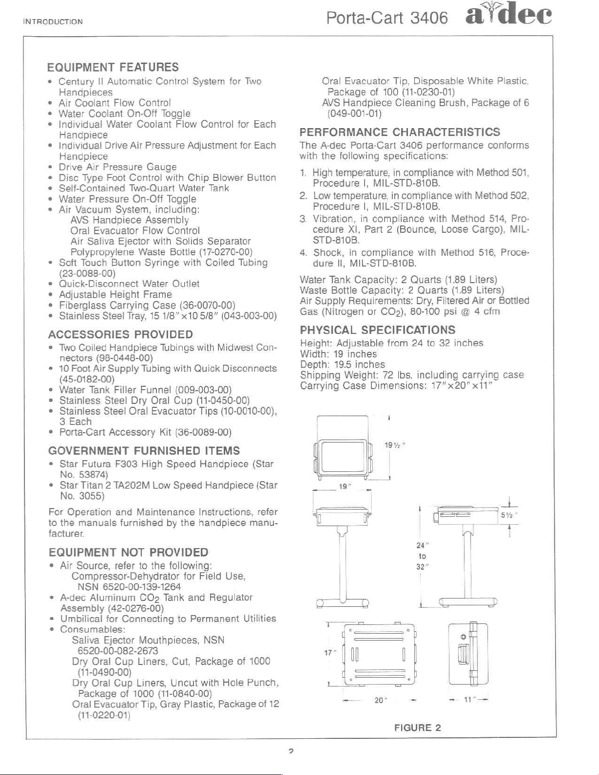
PHYSICAL SPECIFICATIONS
Height:
Width:
Depth:
Shipping
Carrying
Porta-Cart
the
following
temperature,
|,
temperature,
|,
in
XI,
in
compliance
Il,
MIL-STD-810B.
Tank
Capacity: 2 Quarts
Bottle
Capacity: 2 Quarts
Requirements:
(Nitrogen
Adjustable
19
inches
19.5
inches
Weight:
Case
Tip,
Disposable
of
100
(11-0230-01)
Cleaning
CHARACTERISTICS
3406
performance
specifications:
in
compliance
MIL-STD-810B.
in
compliance
MIL-STD-810B.
compliance
Part 2 (Bounce,
with
Dry,
or
CO»),
80-100
from
24
to
72
Ibs.
including
Dimensions:
with
17"x20"
White
Brush,
Loose
Method
Filtered
32
Package
with
with
Method
Cargo),
(1.89
Liters)
(1.89
Air
psi @ 4
inches
carrying
Plastic,
conforms
Method
Method
514,
516,
Proce-
Liters)
or
Bottled
cfm
x11”
of
501,
502,
Pro-
MIL-
case
6
GOVERNMENT
e
Star
Futura
No.
53874)
¢
Star
Titan 2 TA202M
No.
3055)
For
Operation
to
the
manuals
facturer.
EQUIPMENT
e
Air
Source,
Compressor-Dehydrator
NSN
6520-00-139-1264
+
A-dec
Aluminum
Assembly
®
Umbilical
*
Consumables:
Saliva
Dry
Ejector
6520-00-082-2673
Oral
FURNISHED
F303
High
Speed
Low
and
Maintenance
furnished
NOT
refer
by
PROVIDED
to
the
following:
CO:
Tank
(42-0276-00)
for
Connecting
Mouthpieces,
Cup
Liners,
Cut,
Speed
the
for
and
to
Permanent
(11-0490-00)
Dry
Oral
Cup
Package
Oral
Evacuator
of
1000
Liners,
Tip,
Uncut
(11-0840-00)
Gray
Plastic,
(11-0220-01)
ITEMS
Handpiece
Handpiece
Instructions,
handpiece
Field
Use,
Regulator
Utilities
NSN
Package
with
of
Hole
Package
(Star
(Star
refer
manu-
1000
Punch,
of
12
ar
|
Tİ
|
|
|
24"
FIGURE
2
ーー
キー
Ts
e
Page 7
A!
MEC
Porta-Cart
3406
EQUIPMENT
SETUP
SAFETY
Providing
are
followed.
operational
precautions
cautions
and
EQUIPMENT
INSPECTION
1.
During
external
or
2.
Check
vided
page
PRECAUTIONS
that
the
safety
are
associated
procedures.
the
damage
dented
the
and
Government
2.
the
instructions
A-dec
hazards,
required.
with
SETUP
assembly
such
unit.
contents
given
Porta-Cart
and
Observe
standard
of
the
unit,
as
cracked
against
the
Furnished
in
this
manual
3406
presents
no
special
the
normal
dental
check
Accessories
practices
for
obvious
carrying
Items
lists
no
safety
pre-
case
Pro-
on
3.
Inspect
age.
Check
4.
several
Check
5.
hardware.
After
6.
and
a
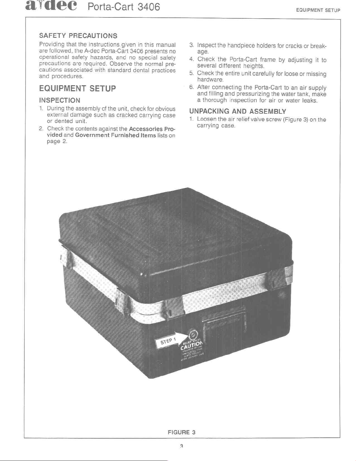
UNPACKING
1.
Loosen
carrying
the
the
different
the
connecting
filling
thorough
the
handpiece
Porta-Cart
entire
pressurizing
and
inspection
AND
air
relief
case.
holders
frame
heights.
carefully
unit
Porta-Cart
the
for
ASSEMBLY
valve
for
by
for
the
or
air
screw
cracks
adjusting
loose
an
to
tank,
water
water
(Figure
or
break-
missing
or
supply
air
make
leaks.
3)
on
it
the
to
FIGURE
3
Page 8
EQUIPMENT
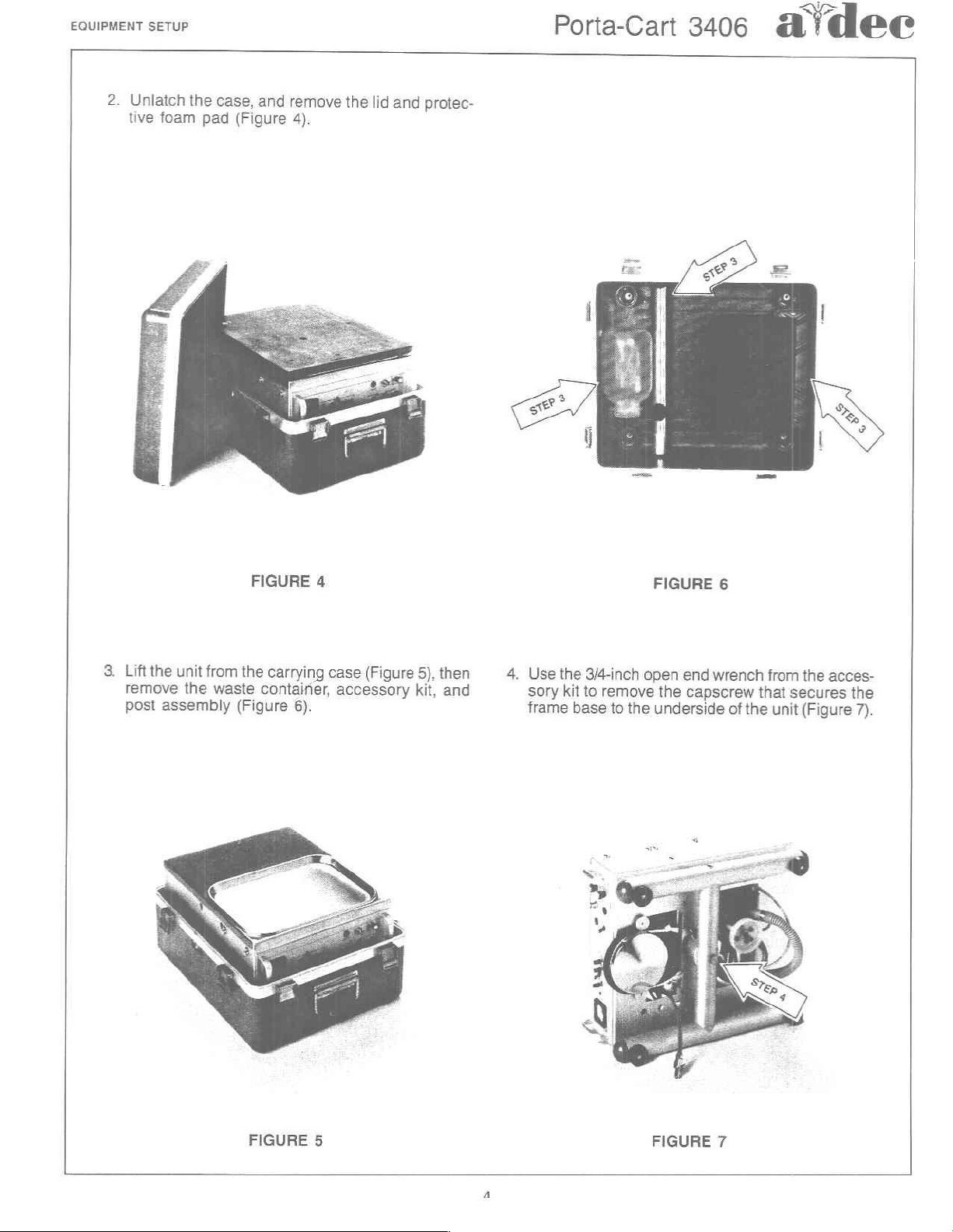
2.
Unlatch
tive
SETUP
foam
the
pad
case,
(Figure
and
remove
4).
the
lid
and
protec-
Porta-Cart
3406
a'dec
3.
Lift
the
remove
post
assembly
unit
the
from
waste
FIGURE
the
carrying
container,
(Figure
6).
4
case
accessory
(Figure
5).
kit,
then
and
4.
Use
the
sory
frame
3/4-inch
kit
to
base
open
remove
to
the
FIGURE
the
underside
6
end
wrench
capscrew
of
that
the
from
secures
unit
the
acces-
the
(Figure
7).
FIGURE
5
FIGURE
7
Page 9
a'cdel
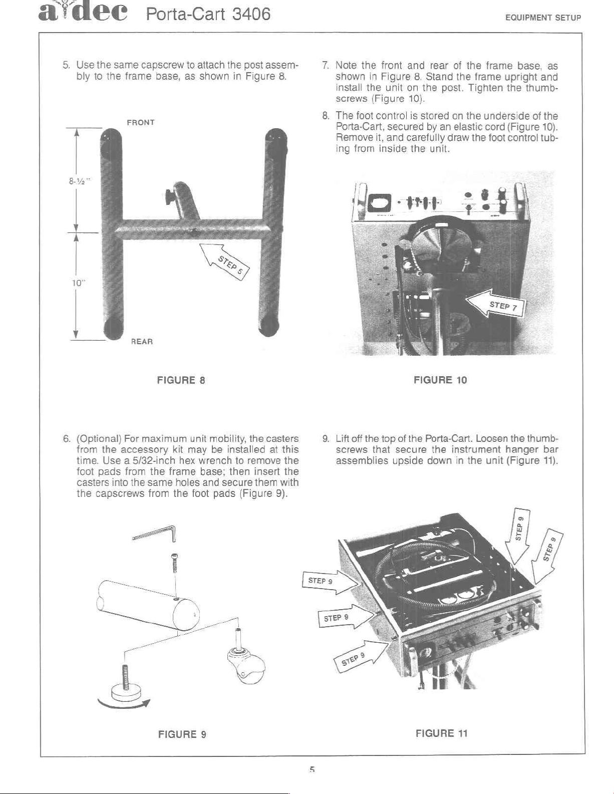
5.
Use
the
bly
to
8-2"
À
10”
same
the
Porta-Cart
capscrew
frame
FRONT
base,
to
attach
as
shown
3406
the
post
in
Figure
assem-
8.
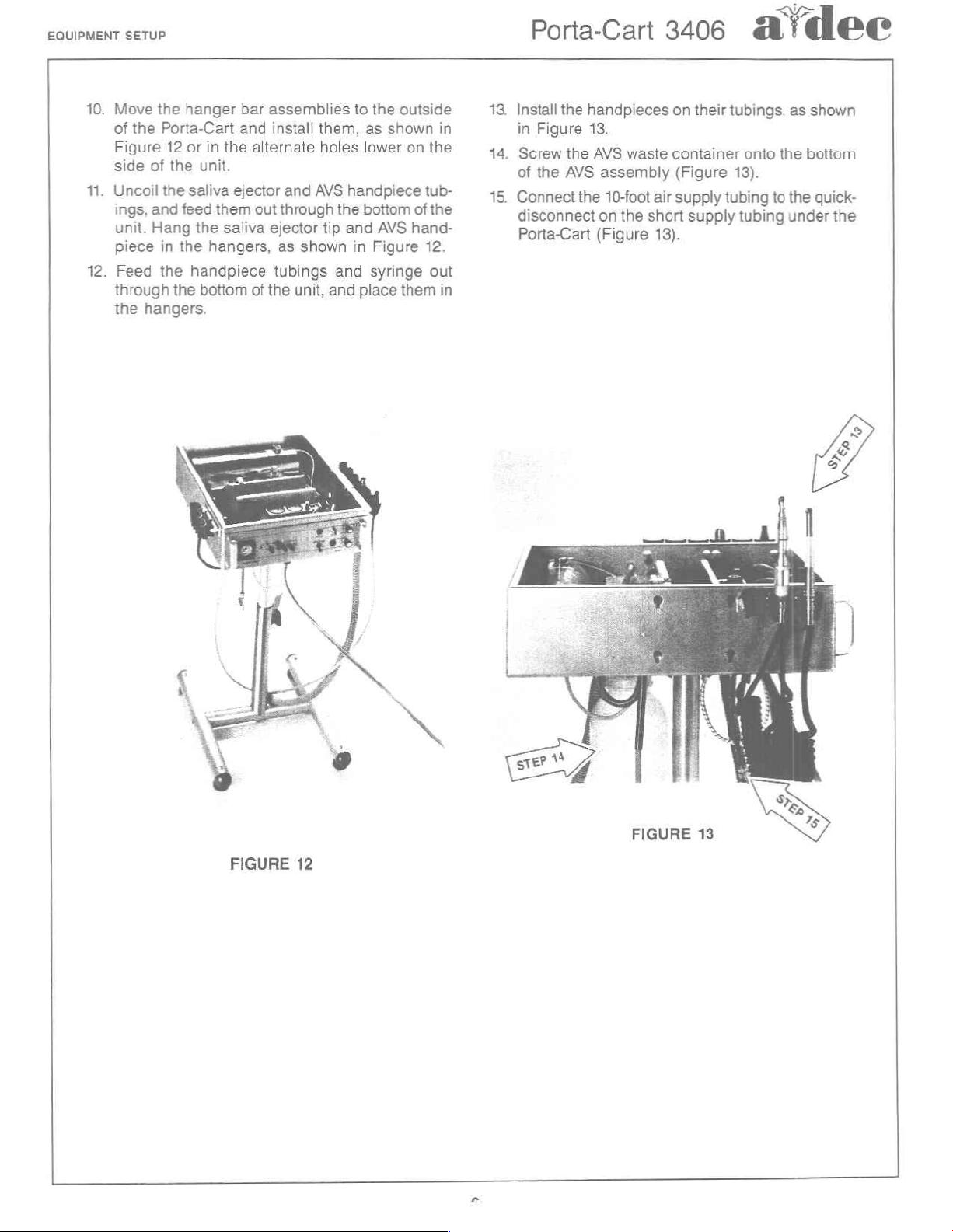
7.
Note
shown
install
screws
8.
The
foot
Porta-Cart,
Remove
ing
from
the
in
the
(Figure
control
it,
inside
front
and
Figure
unit
on
secured
and
carefully
8.
the
10).
is
stored
the
rear
Stand
post.
by
an
draw
unit.
of
the
the
frame
Tighten
on
the
elastic
the
EQUIPMENT
frame
underside
cord
upright
foot
base,
the
thumb-
(Figure
control
and
of
tub-
SETUP
as
the
10).
6.
(Optional)
from
time.
foot
casters
the
REAR
FIGURE
For
maximum
the
accessory
Use a 5/32-inch
pads
from
the
into
the
same
capscrews
from
kit
may
hex
frame
holes
the
8
unit
wrench
base;
and
foot
mobility,
be
installed
to
then
secure
pads
(Figure
the
casters
at
remove
insert
them
this
the
the
with
9).
9.
Liftoff
screws
assemblies
the
that
top
secure
upside
of
the
FIGURE
10
Porta-Cart.
the
down
Loosen
instrument
in
the
unit
the
thumb-
hanger
(Figure
bar
11).
FIGURE
9
FIGURE
11
Page 10
EQUIPMENT
10.
11.
12.
of
side
Uncoil
SETUP
Move
Figure
ings;
unit.
piece
Feed
through
the
the
the
Porta-Cart
12
of
the
the
and
feed
Hang
in
the
the
the
hangers.
hanger
or
saliva
handpiece
in
the
unit.
ejector
them
the
saliva
hangers,
bottom
bar
and
assemblies
install
alternate
out
through
ejector
of
the
them,
holes
and
AVS
tip
as
shown
tubings
unit,
and
to
the
outside
as
shown
lower
on
handpiece
the'battom
and
in
and
place
of
AVS
hand-
Figure
syringe
them
13.
in in
the
tub-
the
12.
out
in
14.
15.
Porta-Cart
Install
the
handpieces
Figure
Screw
of
the
Connect
disconnect
Porta-Cart
13.
the
AVS
AVS
assembly
the
on
(Figure
10-foot
waste
air
the
short
13).
3406
on
their
tubings,
container
(Figure
supply
13).
tubing
supply
tubing
a
onto
to
dee
as
shown
the
bottom
the
under
quick-
the
FIGURE
12
FIGURE
13
Page 11
aídeec
Porta-Cart
3406
OPERATION
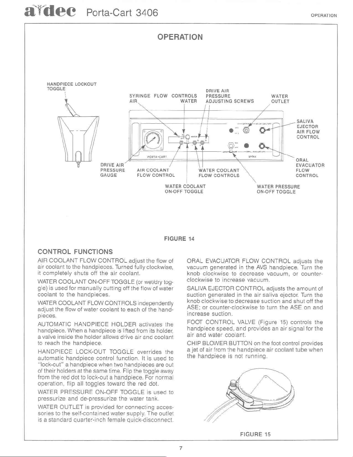
OPERATION
HANDPIECE
TOGGLE
LOCKOUT
SYRINGE
AIR
X
MOM
DRIVE
PRESSURE © AİR
GAUGE
AIR
FLOW
FLOW
/
COOLANT
CONTROL
WATER
ON-OFF
FIGURE
CONTROLS
WATER
©
1
da
_ i i
/
k
A
|
COOLANT
TOGGLE
14
DRIVE
AIR
PRESSURE
ADJUSTING
/ /
yr
SCREWS
À
Water
FLOW
6ΟΟΙΑΝΤ
CONTROLS
WATER
ON-OFF
WATER
OUTLET
|
PRESSURE
TOGGLE
SALIVA
EJECTOR
AIR
FLOW
CONTROL
GRA:
EVACUATOR
FLOW
CONTROL
CONTROL
AIR
COOLANT
air
coolant
it
completely
WATER
gle)
is
used
coolant
WATER
adjust
the
pieces.
AUTOMATIC
handpiece.
a
valve inside
to
reach
HANDPIECE
automatic
“lock-out” a handpiece when
of
their
holders
from
the
operation,
WATER
pressurize
WATER
sories
to
is a standard
FUNCTIONS
FLOW
to
the
handpieces.
shuts
off
COOLANT
for
to
the
COOLANT
flow
When a handpiece
the
handpiece
red
flip
PRESSURE
and
OUTLET
the
ON-OFF
manually
handpieces.
FLOW
of
water
HANDPIECE
the
holder
handpiece.
LOCK-OUT
at
the
same
dot
to
lock-out a handpiece.
all
toggles
de-pressurize
is
provided
self-contained
quarter-inch
CONTROL
the
cutting
CONTROLS
coolant
allows
control
toward
ON-OFF
Turned
air
coolant.
TOGGLE
off
to
HOLDER
is
lifted
drive
TOGGLE
function.
two
handpieces
time.
Flip
TOGGLE
the
for
connecting
water
female
adjust
each
the
supply.
quick-disconnect.
the
flow
fully
clockwise,
(or
wet/dry
the
flow
of
independently
of
the
activates
from
its
holder,
air
and coolant
overrides
It
is
used
are
the
toggle
For
normal
red
dot.
is
used
water
tank.
acces-
The
of
tog-
water
hand-
the
the
to
out
away
to
outlet
ORAL
vacuum
knob
clockwise
SALIVA
suction
knob clockwise
ASE;
increase
FOOT
handpiece
air
CHIP
a
the
EVACUATOR
clockwise
or
CONTROL
and water
BLOWER
jet
of
air
handpiece
generated
to
increase
EJECTOR
generated
counter-clockwise
suction.
speed,
coolant.
from
in
to
decrease
CONTROL
in
to
decrease
VALVE
and
BUTTON
the
handpiece
is
not
FLOW
the
AVS
vacuum.
the
air
to
(Figure
provides
on
running.
CONTROL
handpiece.
vacuum,
adjusts
saliva
suction and
turn
the
air
ejector.
the
15)
an
air
foot
control
coolant
the
signal
adjusts
Turn
or
counter-
amount
Turn
shut
off
ASE
on
controls
for
provides
tube
when
the
the
of
the
the
and
the
the
FIGURE
15
Page 12
OPERATION
Porta-Cart
34066
d'dec
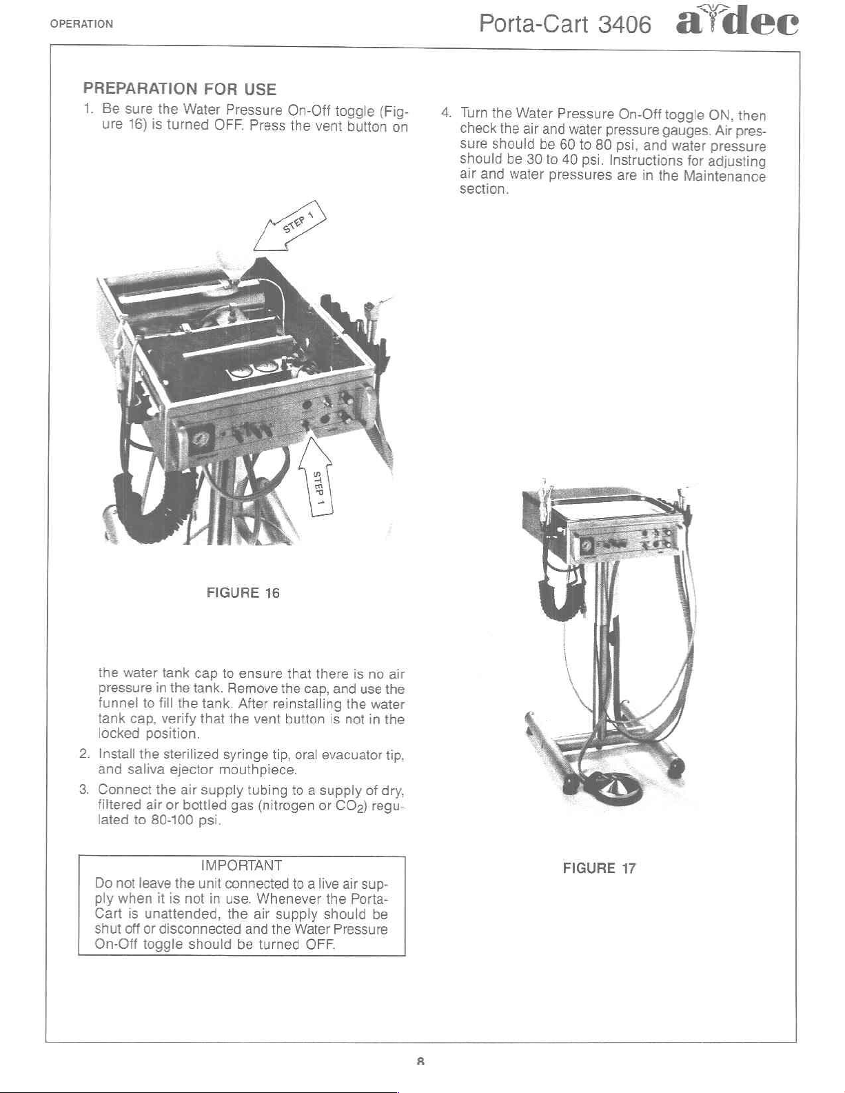
PREPARATION
1.
Be
sure
the
ure
16)
is
turned
FOR
Water
OFF.
USE
Pressure
Press
On-Off
the
vent
toggle
button
(Fig-
on
4.
Turn
check
Sure
should
air
section.
the
the
should
and
Water
air
30
be
water
Pressure
and
water
be
60
to
psi.
40
to
pressures
On-Off
pressure
80
psi,
and
Instructions
are
in
the
toggle
gauges.
ON,
water
pressure
adjusting
for
Maintenance
Air
then
pres-
the
pressure
funnel
tank
locked
2.
Install
and
3.
Connect
filtered
lated
Do
not
ply
Cart
shut
On-Off
water
tank
in
to
fill
cap,
verify
position.
the
sterilized
saliva
the
air
to
80-100
leave
when
it
is
unattended,
off
or
disconnected
togale
FIGURE
cap
the
tank.
the
tank.
that
ejector
air
supply
or
bottled
psi.
IMPORTANT
the
unit
is
not
should
16
to
ensure
Remove
After
the
vent
syringe
mouthpiece.
tubing
gas
(nitrogen
connected
in
use.
Whenever
the
air
and
be
turned
that
there
the
cap,
and
reinstalling
button
tip,
oral
to a supply
to a live
supply
the
Water
the
is
not
evacuator
or
COs)
air
the
should
Pressure
OFF.
is
no
air
use
the
water
in
the
tip,
of
dry,
regu-
sup-
Porta-
be
FIGURE
17
Page 13
aídee
USE
Soft
DESCRIPTION
is a three-way
change
straightforward
maintenance.
can
be
Maintenance
CHANGING
and
pull
and
push
nut
by
When
sure
way
in
be
is
OF
THE
Touch
the
ejected
pressed.
Button
autoclavable
performed
THE
the
used
it
in
hand
changing
that
the
into
the
syringe
from
Porta-Cart
ACCESSORIES
Syringe
A-dec’s
air
and
design,
Any
service
by
section
TIP
tip
as
far
until
it
the
replacement
syringe. A tip
could
the
Soft
water
syringe
tip.
Because
this
syringe
that
following
of
this
Loosen
straight
as
it
will
is
just
snug.
IMPORTANT
autoclavable
tip
that
cause
syringe
3406
Touch
out.
go,
when
Button
featuring a quick-
of
its
requires
will
ever
be
the
instructions
book.
the nut a half
Insert
the
then
retighten
syringe
is
pushed
is
not
fully
the
water
button
the
air
Syringe
simple,
very
little
required
in
the
turn
new
tip
the
tip,
be
all
the
seated
to
button
Air
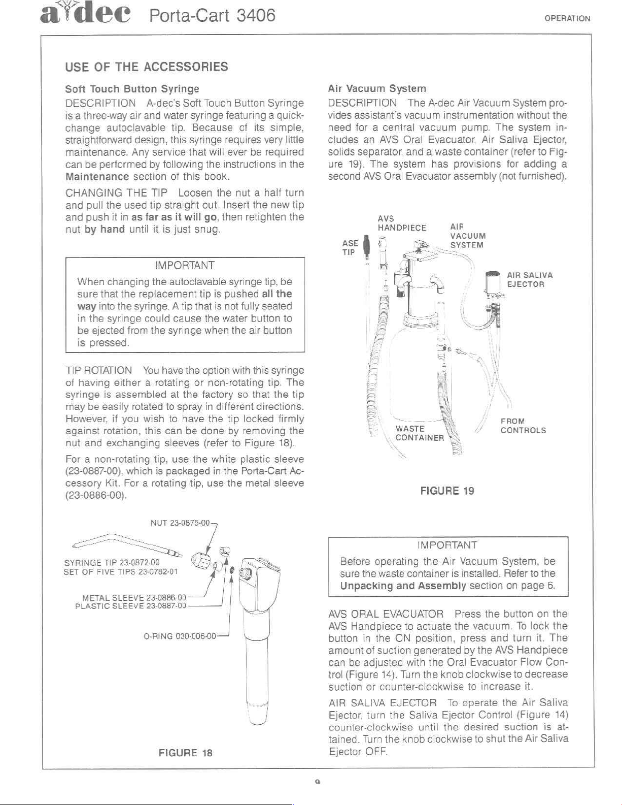
DESCRIPTION
vides
need
cludes
solids
ure
second
Vacuum
assistant’s
for a central
separator,
19).
an
AVS
The
AVS
AVS
HANDPIECE
System
vacuum
Oral
and a waste container
system
Oral
Evacuator
The
A-dec
vacuum
Evacuator,
has
Air
Vacuum
instrumentation
pump.
provisions
assembly
AIR
VACUUM
SYSTEM
Air
System
The
Saliva
(refer
for
(not
AIR
EJECTOR
OPERATION
pro-
without
system
furnished).
Ejector,
to
Fig-
adding
SALIVA
the
in-
a
TIP
ROTATION
of
having
syringe
may
However,
against
nut
For a non-rotating
(23-0887-00),
cessory
is
be
easily
rotation,
and
exchanging
Kit.
You
have
the
either a rotating
assembled
rotated
if
you
which
For a rotating
wish
this
tip,
is
at
the
to
spray
to
have
can
be
sleeves
use
packaged
tip,
option
or
non-rotating
factory
in
different
the
done
(refer
the
white
in
use
(23-0886-00).
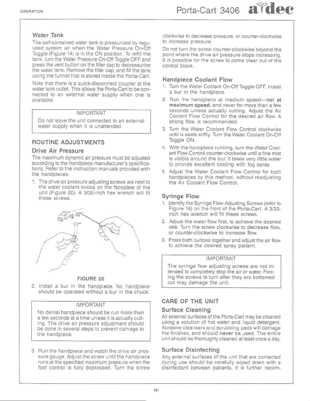
NUT 23-0875-00—
SYRINGE
SET
OF
FIVE TIPS
METAL
PLASTIC
TIP
SLEEVE
SLEEVE
—
23-0872-00
23-0782-01
23-0886-00
23-0887-00
O-RING
030-006-00
FIGURE
18
with
so
that
tip
locked
by
removing
to
Figure
plastic
the
Porta-Cart
the
metal
this
syringe
tip.
The
the
tip
directions.
firmly
the
18).
sleeve
Ac-
sleeve
WASTE
CONTAINER
x
Before
sure
Unpacking
AVS
AVS
button
amount
can
trol
suction
AIR
Ejector,
counter-clockwise
tained.
Ejector
operating
the
waste
ORAL
Handpiece
in
the
of
suction
be
adjusted
(Figure
SALIVA
14).
or
counter-clockwise
turn
Turn
OFF.
container
and
EVACUATOR
to
ON
with
Turn
EJECTOR
the
Saliva
the
knob
FIGURE
IMPORTANT
the
Air
is
Assembly
Press
actuate
position,
generated
the
until
the
the
Oral
knob
To
Ejector
the
clockwise
FROM
и
CONTROLS
19
Vacuum
installed.
section
press and
by
Evacuator
clockwise
to
operate
desired
System,
Refer
the
button
vacuum.
the
AVS
increase
the
Control
suction
to
shut
to
on
page
To
lock
turn
it.
Handpiece
Flow
to
decrease
it.
Air
(Figure
the
Air
be
the
6.
on
the
the
The
Con-
Saliva
14)
is
at-
Saliva
Page 14
OPERATION
Porta-Cart
3406
d
dee
Water
The
lated
Toggle
tank,
press
the
using
Note
water
nected
available.
Tank
self-contained
system
(Figure
turn
the
water
the
that
tank
to
Do
not
water
supply
ROUTINE
Drive
The
according
tions.
the
1.
2.
Air
maximum
Refer
handpieces.
The
drive
the
water
unit
(Figure
these
screws.
Install a bur
should
No
dental
a
few
seconds
ing.
The
be
done
the
handpiece.
water
air
when
the
14)
is
in
the
the
Water
Pressure
vent
button
tank.
funnel
there
outlet.
an
leave
on the
Remove
that
is a quick-disconnect
This
external
the
when
the
is
stored
allows
water
IMPORTANT
unit
connected
it
ADJUSTMENTS
Pressure
dynamic
to
the
handpiece
to
the
air
pressure
coolant
20). A 3/32-inch
be
operated
handpiece
drive
in
several
air
instruction
knobs
FIGURE
in
the
without a bur
IMPORTANT
should
at a time
air
pressure
steps
tank
is
pressurized
Water
ON
filler
filler
the
is
unattended.
pressure
manufacturer’s
adjusting
on
handpiece.
unless
to
Pressure
position.
On-Off Toggle
cap
cap,
inside
Porta-Cart
supply
to
must
manuals
screws
the
faceplate
hex
20
be
run
it
is
adjustment
prevent
by
On-Off
To
refill
OFF
to
depressurize
and
fill
the
the
Porta-Cart.
coupler
to
be
when
one
an
external
be
adjusted
specifica-
provided
are
next
wrench
No
handpiece
in
the
chuck.
more
than
actually
cutt-
should
damage
regu-
the
and
tank
at
the
con-
with
of
the
will
to
is
to
fit
clockwise
to
increase
Do
not
point
It
is
control
Handpiece
1.
Turn
a
2.
Run
maximum
seconds
Coolant
strong
.
Turn
until
Toggle
.
With
ant
is
to
.
Adjust
handpieces
the
Syringe
1.
Identify
Figure
inch
.
Adjust
rate.
or
.
Press
to
The
tended
ing
out
CARE
Surface
All
external
using a solution
Abrasive
the
finishes,
unit
to
decrease
pressure.
turn
the
where
possible
the drive
for
block.
Coolant
the
Water
bur
in
the
the
handpiece
speed,
unless
Flow
flow
is
the
Water
is
seats
ON.
the
handpiece
Flow
Control
visible
achieve
around
provide
Air
counter-clockwise
syringe
the
may
the
Coolant
Flow
the
14)
hex
wrench
the
water
Turn
the
both
to
completely
screws
damage
OF
THE
excellent
Water
by
Syringe
on
buttons
the
flow
Cleaning
surfaces
cleansers
and
should
be
thoroughly
pressure,
screw
counter-clockwise
air
pressure
the
screw
to
come
Flow
Coolant
handpiece.
Control
recommended.
Coolant
softly.
counter-clockwise
this
Flow
the
flow
screw
desired
IMPORTANT
to
On-Off
at
medium
and
never
actually
Turn
the
Coolant
Flow Adjusting
front
will
together
adjusting
turn
the
cutting.
for
the
Flow
the
Water
running,
bur.
It
takes
cooling
Flow
method,
Control.
of
the
fit
these
first,
to
clockwise
to
increase
and
spray
screws
stop
the
after
they
unit.
UNIT
of
the
Porta-Cart
of
hot
water and
and
scrubbing
should
never
cleaned
or
counter-clockwise
beyond
stops
increasing.
clear
Toggle
for
desired
Control
turn
with
without
Porta-Cart. A 3/32-
achieve
pattern.
air
be
at
OFF.
speed—not
more
Adjust
Coolant
the
Water
until a fine
very
fog
spray.
Control
readjusting
Screws
screws.
the
to
decrease
flow.
adjust
the
are
or
water.
are
bottomed
may
be
liquid
detergent.
pads
will
used.
The
least
once a day.
than a few
air
clockwise
little
out
of
Install
the
flow.
On-Off
Cool-
water
for
both
(refer
desired
flow,
air
flow
not
in-
Forc-
cleaned
damage
entire
the
the
Air
mist
at
A
to
3.
Run
the
handpiece
sure
gauge.
runs
at
foot
control
Adjust
the
specified
is
and
the
maximum
fully
watch
screw
depressed.
until
the
drive
the
handpiece
pressure
Turn
the
air
when
screw
pres-
the
Surface
Any
external
during
disinfectant
10
Disinfecting
surfaces
use
should
between
of
the
be
carefully
patients.
unit
wiped
It
that
is
further
are
contacted
down
with
a
recom-
Page 15
a
dee
Porta-Cart
3406
OPERATION
mended
is
in
disinfectant.
The
danger
(1)
to
Cydex*
producis containing
propyi
sult a full-service
the
Cleaning
After
rinsed
piece
through
water
mouthpiece
sterilization.
Daily
to
prevent
cleaners
systems
you
manufacturer's
sudsing
Use
Push
clean
hold
purged
The rubber
easily
stall
Do
The
equipped
ing
cleaned
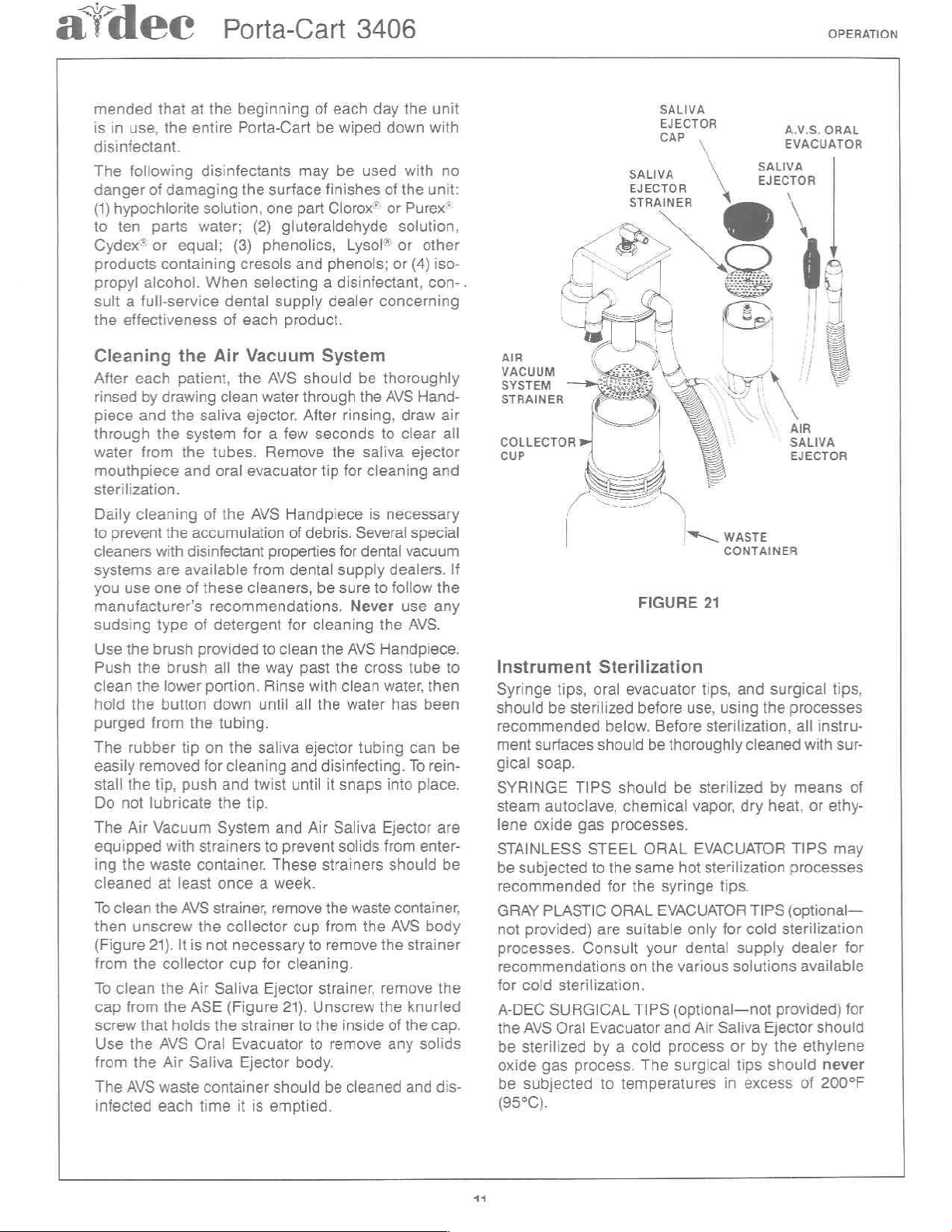
To
then
(Figure
from
To
cap
screw
Use
from
The
infected
that
at
use,
the
entire
following
of
hypochlorite
ten
parts
or
alcohol.
effectiveness
disinfectants
damaging
water;
equal;
the
each
patient,
by
drawing
and
the
saliva
the
system
from
the
and
cleaning
the
accumulation
with
disinfectant
are
available
use
one
of
type
of
the
brush
provided
the
brush
the
lower
the
button
from
the
tip
removed
the
tip,
push
not
lubricate
Air
Vacuum
with
strainers
the
waste
clean
unscrew
21).
the
clean
from
that
the
the
AVS
container.
at
least
the
AVS
the
itis
collector
the
Air
the
ASE
holds
AVS
Oral
Air
Saliva
waste
each
time
the
solution,
When
Air
tubes.
oral
of
these
recommendations.
detergent
all
portion.
down
on
for
strainer,
not
Saliva
the
container
beginning
Porta-Cart
the
one
(2)
(3)
phenolics,
cresols
selecting a disinfectant,
dental
of
each
Vacuum
the
clean water
ejector. After
for a few
Remove
evacuator
the
AVS
from
cleaners,
to
the
way
Rinse
until
tubing.
the
saliva
cleaning
and
twist
the
tip.
System
to
once a week.
collector
necessary
cup
for
Ejector
(Figure
strainer
Evacuator
Ejector
it
is
of
each
be
wiped
may
be
surface
supply
finishes
part
Clorox®
gluteraldehyde
Lysol®
and
phenols;
dealer
product.
System
AVS
should
through
Handpiece
of
debris.
properties
dental
for
clean
past
with
all
ejector
and
until
and
Air
prevent
These
remove
cup
to
cleaning.
21).
to
to
body,
should
emptied.
be
the
rinsing,
seconds
the
tip
for
Several
for
supply
be
sure
Never
cleaning
the
AVS
the
clean
the
water
tubing
disinfecting.
it
snaps
Saliva Ejector
solids
strainers
the
waste
from
remove
strainer,
Unscrew
the
inside
remove
be
cleaned
day
the
down
used
with
of
the
or
Purex*
solution,
or
or
(4)
concerning
thoroughly
AVS Hand-
draw
to
clear
saliva
dental
cross
the
ejector
cleaning
is
necessary
special
vacuum
dealers.
to
follow
use
the
AVS.
Handpiece.
tube
water,
has
can
To rein-
into
from
should
container,
AVS
the
strainer
remove
the
knurled
of
the
any
and
unit
with
no
unit:
other
iso-
con-
air
all
and
If
the
any
to
then
been
be
place.
are
enter-
be
body
the
cap.
solids
dis-
.
AIR
VACUUM
SYSTEM
STRAINER
COLLECTOR
CUP
Instrument
Syringe
should
recommended
ment
gical
SYRINGE
steam
lene
STAINLESS
be
subjected
recommended
GRAY
not
provided)
processes.
recommendations
for
cold sterilization.
A-DEC
the
AVS
be
sterilized
oxide
be
subjected
(95°C).
SALIVA
TOR
SALIVA
EJECTOR
STRAINER
|
tips,
oral
be
sterilized
surfaces
soap.
TIPS
autoclave,
oxide
gas
STEEL
to
PLASTIC
Consult
SURGICAL
Oral
Evacuator
by a cold
gas
process.
Sterilization
evacuator
before
below.
should
should
chemical
processes.
the
same
for
the
ORAL
are
suitable
on the
TIPS
to
temperatures
E
FIGURE
use,
Before
be
thoroughly
be
vapor,
ORAL
your
The
EVACUATOR
hot
syringe
EVACUATOR
only
dental
various
(optional—not
and
Air
process
surgical
ANS.
κ
\
\
EVACUATOR
CR
、
AIR
SALIVA
EJECTOR
WASTE
CONTAINER
21
tips,
and
surgical
using
the
processes
sterilization,
cleaned
sterilized
sterilization
tips.
for
Saliva Ejector
by
means
dry heat,
TIPS
processes
TIPS
(optional
cold
sterilization
supply
solutions available
or
tips
in
excess
dealer
provided)
by
the
should
ORAL
tips,
all
instru-
with
sur-
or
ethy-
may
for
for
should
ethylene
never
of
200°F
of
—
11
Page 16
PREPARATION
OR
TRANSPORTATION
FOR
STORAGE
Porta-Cart
3406
A
dee
SYSTEM
The
following
Cart
is
eight
hours.
1.
Turn
the
quick-disconnect
Accessory
on
the
2.
Turn
allow
the
Water
Off
toggle
fitting.
3.
Clean
tor
by
the
Air
4.
Empty
disinfect
5.
Clean
by
the
6.
Disconnect
sure
button.
7.
Thoroughly
fied
in
SHUT-DOWN
steps
being
shut
down
the
Water
Pressure
Kit
(see
faceplate.
the
Water
the
the
following
Vacuum
the
it.
and
manufacturer.
from
the
Pressure
water
tank
Outlet;
OFF,
and
AVS
Handpiece
the
AVS
waste
lubricate
the
air
the
unit
clean
Care
of
should
then
be
taken
for
any
On-Off
fitting
page
52)
On-Off
to
completely
turn the
remove
and
instructions
System
supply
the
the
section
container,
the
handpieces,
tube,
by
pressing
external
Unit
when
the
period
from
into
Water
the
the
surfaces
section
in
excess
toggle
and
OFF.
the
Porta-Cart
the
Water
toggle
guick-disconnect
in
then
the
drain
Pressure
Air
Saliva
the
Cleaning
on
page
clean
as
specified
bleed
syringe
as
on
page
ON,
through
air
Porta-
of
Insert
Outlet
and
On-
Ejec-
11.
and
pres-
air
speci-
10.
PREPARATION
TRANSPORTATION
PRELIMINARY
1.
Conduct
Down
2.
Clean
System
tions
section
3.
Pack
by
REPACKING
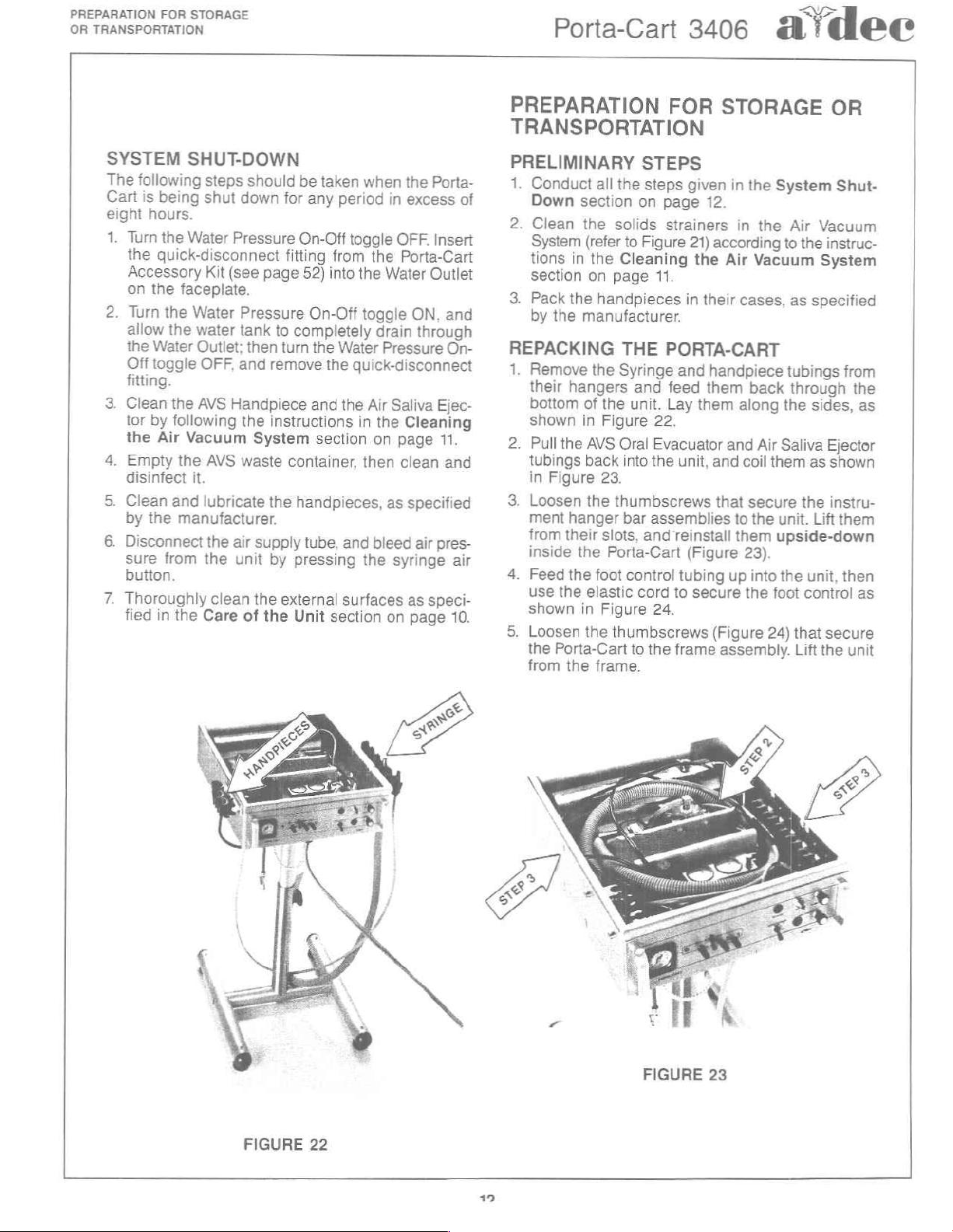
1.
Remove
their
bottom
shown
2.
Pull
tubings
in
3.
Loosen
ment
from
inside
4.
Feed
use
shown
5.
Loosen
the
from
section
the
(refer
in
the
on
the
the
manufacturer.
the
hangers
of
in
the
AVS
back
Figure
the
hanger
their
the
the
foot
the
elastic
in
the
Porta-Cart
the
frame.
STEPS
all
the
steps
on
solids
to
Figure
Cleaning
page
11.
handpieces
THE
Syringe
and
the
unit.
Figure
23.
slots,
Porta-Cart
Figure
22,
Oral
Evacuator
into
the
thumbscrews
bar
assemblies
and
control
cord
24.
thumbscrews
to
the
FOR
page
strainers
PORTA-CART
feed
Lay
STORAGE
given
in
12.
in
21)
according
the
Air
in
their
cases,
and
handpiece
them
them
along
and
unit,
and
that
to
reinstall
(Figure
tubing
to
frame
them
up
secure
(Figure
assembly.
the
System
the
to
Vacuum
tubings
back
the
Air
Saliva
coil
them
secure
the
unit.
upside-down
23).
into
the
the
foot
24)
OR
Shut-
Air
Vacuum
the
instruc-
System
as
specified
through
sides,
Ejector
as
shown
the
instru-
Lift
unit,
control
that
secure
Lift
the
from
the
as
them
then
as
unit
FIGURE
22
FIGURE
23
Page 17
ai
@e@e@
Porta-Cart
3406
PREPARATION
OR
FOR
TRANSPORTATION
STORAGE
6.
7.
8.
If
a
stall
Pack
Use
sory
post
Use
to
the
casters
5/32-inch
the
foot
the
casters
the
3/4-inch
kit
to
remove
assembly
the
same
the
underside
FIGURE
are
installed
hex
wrench
pads
open
to
capscrew
(refer
into
end
the
capscrew
the
of
the
24
on
to
remove
to
Figure 9 on
the
accessory
wrench
frame
to
secure
unit
the
frame
them
from
that
base.
the
(Figure
base,
and
page
kit
case.
the
acces-
secures
frame
25).
use
rein-
5).
the
base
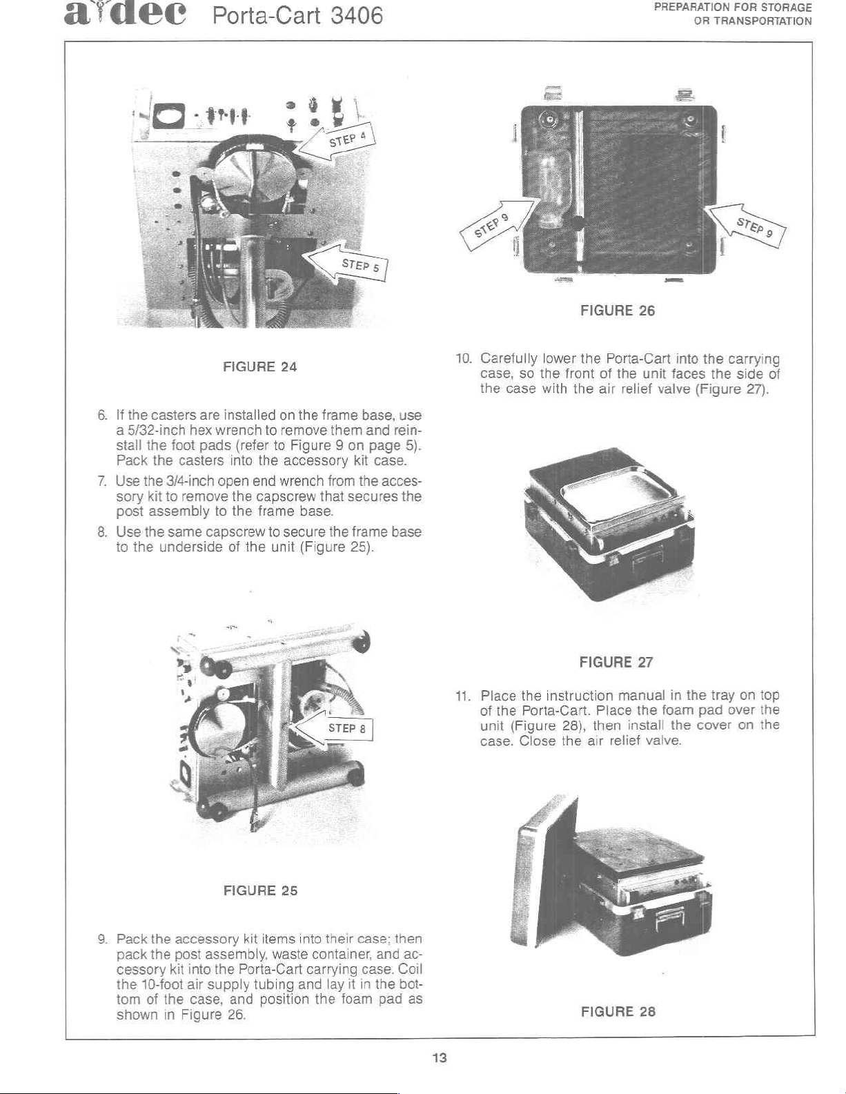
10.
Carefully
case,
the
Place
11.
of
unit
case.
so
the
case
the
the
Porta-Cart.
(Figure
Close
FIGURE
lower
the
front
with
the
air
FIGURE
instruction
Place
28),
then
the
air
26
Porta-Cart
of
the
unit
relief
valve
27
manual
the
install
relief
valve.
into
faces
in
foam
the
the
carrying
the
(Figure
the tray
pad
over
cover
side
27).
on
on
of
top
the
the
FIGURE
9.
Pack
the
accessory
pack
the
post
assembly,
cessory
the
tom
shown
kit
into
the
Porta-Cart
10-foot
air
of
the
case,
in
Figure
supply
and
26.
kit
items
waste
tubing
position
25
into
and
their
case:
container,
carrying
the
lay
case.
it
in
foam
and
the
pad
then
ac-
Coil
bot-
as
FIGURE
13
28
Page 18
MAINTENANCE
MAINTENANCE
Porta-Cart
3406
a@idee
GENERAL
Parts
In
find
sible
itself
body,
ton.
age,
careful
A
Equipment
that
When
kets
new
old
check
Cleaning
When
ponent
and
lubricant
pervious
cleaner
be
clear,
Inspection
the
Troubleshooting
references
defects.
(usually
and
Defects
so an
examination
magnifier,
are
too
servicing
or
diaphragms,
ones
gasket
for
servicing
disassembled
inspected
recommended
to
is a hot
done
with a soft,
hot
water,
SERVICE
to
the
The
seal
an
O-ring),
the
O-ring
in
any
inspection
as
shown
section,
small
components
when
reassembling
or
diaphragm
pin
holes
Internal
dental
for
chemical
detergent
then
INFORMATION
Guides
“seal
area”
area
the
groove
of
these
of
the
of
all
sealing
in
the
is
essential
to
see
otherwise.
it
is
generally
is
or
cracks.
Parts
systems,
should
defects
lint-free
before
for
these
solvents,
solution.
cloth.
rinse
them
in
this
as
is
comprised
bore
or
in
the
valve
may
result
seal
parts
Special
for
that
have
advisable
the
components.
to
be
reused.
the
parts
be
thoroughly
reassembly.
parts
so
the
Any
Flush
in
isopropyl
manual
location
of
the
seat
in
the
stem
in
seal
area
includes
and
surfaces.
Tools
detecting
rubber
to
carefully
of
any
cleaned
is
largely
most
effective
wiping
all
parts
alcohol.
you
will
of
pos-
seal
valve
or
pis-
leak-
and
flaws
gas-
install
If
the
com-
The
im-
should
with
Lubrication
A-dec
high
lubricating
oral
the
Lubricant.
a
Before
of
will
seal
inserting
A-dec
The
cially
A-dec
When
although
theless
Crimps
short,
Remember
ing
length.
Silicone
quality
evacuator
A-dec
silicone
prevent
bores
silicone
the
lubricant
installing
grease.
the
should
stems
Tubing
tubing
rarely
used
engineered
tubing
troubleshooting
so
this
can
are
that
when
becomes
for
tubing
become
often
it
Lubricant,
base
internal
valves.
O-rings,
O-rings
or
throughout
for
replacement.
is
installing
moving
An
is
Dow-Corning
always
This
makes
from
also
be
pistons.
durability
the
is
resistant
crimped
caused
stretched
crimped,
part
no.
grease
parts,
acceptable
apply a light
installation
being
lightly
A-dec
system,
by
any
and
to
and
the
at
the
tubing
and
lubricated
dental
long
bear
crimping,
obstruct
tubing
barb
98-0090-00,
that
is
ideal
O-rings,
substitute
No.
103
Silicone
coating
easier,
damaged.
before
units
is
life.
Use
in
mind
it
never-
the
being
connection.
that
slack
allow
adequate
is
a
for
and
for
and
The
spe-
only
that
flow.
too
tub-
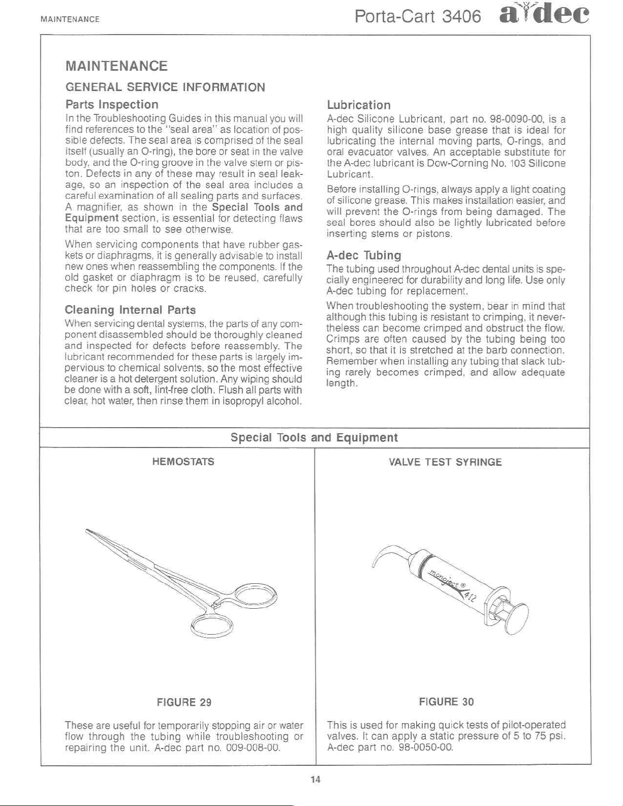
HEMOSTATS
FIGURE
29
Special
Tools
and
Equipment
VALVE
TEST
FIGURE
SYRINGE
30
These
flow
are
through
repairing
useful
the
the
unit.
for
temporarily
tubing
A-dec
stopping
while
troubleshooting
part
no.
air
or
009-008-00.
water
or
This
is
used
valves.
A-dec
It
can
part
no.
14
for
making
apply a static
98-0050-00.
quick
tests
of
pressure
pilot-operated
of 5 to
75
psi.
Page 19

aídeec
Porta-Cart
3406
MAINTENANCE
Use
an
A-dec
range.
points
no.
Barbed
part
A-dec
1/8-inch
This
while
026-078-00.
Fitting,
no.
023-028-00;
part
TEST
FIGURE
air
pressure
is
for
checking
troubleshooting
Also
Washer
Tee
no.
023-014-00;
tubing,
A-dec
GAUGE
It
31
gauge
air
the
required
and
Sleeve
Barb
and a two-foot
part
no.
with a 0-100
pressure
system.
for
use
of
Clamp
and
Sleeve
024-015-00.
at
A-dec
this
Kit,
Clamp
length
psi
various
part
gauge:
A-dec
Kit.
of
These
snap
A-dec
snap
rings,
and
part
SNAP
ring
pliers
fit
no.
009-007-00.
RING
FIGURE
are
all
sizes
PLIERS
for
both
used
33
inside
in
A-dec
and
outside
equipment.
These
tubing
014-00.
modified
onto
the
TUBING
FIGURE
pliers
barbed
PLIERS
32
are
used
fittings.
for
pushing
A-dec
part
no.
O-RING
1/8-inch
009-
INSTALLATION
This
is a 10X
miniature
POCKET
magnifier
valve
parts.
MAGNIFIER
FIGURE
for
A-dec
TOOLS
3
Align
tool
groove
4.
with
tne
O-ring
in
the
stem.
Slide
the
O4
34
inspecting
part
no.
for
defects
009-009-00.
in
These
field,
tools
enable
on
most
A-dec
you
to
make
miniature
quick
components.
repairs,
The
FIGURE
in
the
tools
35
in
this
set
eguipment.
fit
the
four
smallest
A-dec
part
no.
O-ring
009-013-00.
sizes
in
A-dec
Page 20

MAINTENANCE
=
Porta-Cart
3406
4Ÿdec
BASIC
Given
of
go
tells
removing
This
every
so
be
If
the
rect
are
ponents
Neither
(No
1.
2.
3. Is
TROUBLESHOOTING
proper
reliable
wrong
what
troubleshooting
problem
that
you
repaired
procedures
the
problem,
given
in
of
of
Air
or
Does
the
Yes:
Check
tubing.
Control
No:
Proceed
Is
the
air
turned
Yes:
Proceed
No:
Correct
re-test
the
air
Yes:
Refer
No:
Connect
unit.
care,
your
service.
with
can
the
can quickly
the
the
supply
ON
In
the
unit,
be
done
unit
for
that
could
without
the
Water)
syringe
supply
special
given
much
sections
Porta-Cart
Handpieces
for a pinched
If
the
section
to
Step
(compressor
and
operating
with
any
problems
the
unit.
tubing
to
the
Regulators
the
air
Porta-Cart
the
event
this
in
repair.
guide
is
arise.
identify
training
here
do
more
covering
system.
work?
tubing
is
on
2.
Step
3.
properly
supply
will
provide
that
something
troubleshooting
the
operatory,
not
intended
Rather
the
problems
not
identify
detailed
the
to
it
is
designed
that
or
equipment.
and
instructions
individual
Work
or
crimped
okay,
page
or
bottled
properly?
in
the
section
tubing,
foot
refer
to
28.
gas
air
supply.
connected?
on
and
re-test
the
system)
page
years
does
guide
before
isolate
can
cor-
com-
control
Foot
then
19.
the
No
Water
1.
Test
Yes:
No:
2.
Check
Toggle
OPEN?
Yes:
No:
3.
Does
Yes:
No:
Insufficient
1.
Does
Yes:
No:
2.
Check
show a pressure
Yes:
No:
3.
Watch
ing
by
Yes:
the
Proceed
Verify
ne
N.
the
ON?
Proceed
Set the
unit.
the
Refer
tion
Refer
the
Proceed
Refer
cedure
on
the
Proceed
Refer
the
the
syringe
more
Remove
to
the
Coolant
syringe.
Water
handpiece
on
problems
page
system
than
page
No:
Refer
From
Does
with
Step
that
there
is
Pressure
controls.
Are
controls
to
the
page
to
the
Drive
to
the
in
system
to
the
instructions
Is
the
Water
with
Step
Century
20.
Signal
Air
affect
to
Step
Drive
the
Routine
10.
air
of
at
to
Step
Regulators
air
pressure
air
button.
15
psi?
and
inspect
as
air
18.
to
the
Foot
Control
Either
it
spray
2.
water
in
On-Off
the
Water
Coolant
3.
specified
coolant
II
Control
Relay
section
Pressure
both
2.
Air
Pressure
Adjustments
pressure
least
60
3.
secton
gauge
Does
the
air
in
the
Filters
section
Handpiece
water?
the
tank
toggle
Coolant
work?
handpieces?
gauge.
psi?
the
filter
is
Flow
and
re-test
System
on
adjusting
on
while press-
pressure
according
section
on
and
that
turned
On-Off
Controls
the
sec-
page
30.
pro-
section
Does
it
page
19.
drop
on
page
28.
16
Page 21

Porta-Cart
3406
MAINTENANCE
SALIVA
L!
Esecron
see
AIR
Le
AIR
vacuum
SYSTEM
10072900
WASTE-
CONTAİNER
—E
SCHEMATIC
AVS
&
TUBING
@|
‘ость
品 一
DIAGRAM
HANDPIECE
ASSY
NEEDLE
VALVES
(2
EA)
19-0361-00
QUICK-DISCONNECT
925-05-00
e a
26002300
MINEFILTER
19-0100-00
WATER
REGULATOR
24028100
AIR
REGULATOR
02504100
FILTER
026-073-00
026.073
00
CENTURY
CONTROL
56019100
ASSY
AUTOMATIC
HOLDERS
se.0528.00
HANDPIECE
SOFT
TOUCH
BUTTON
SYRINGE
23-0088-00
AIR
IN
17
FOOT
CONTROL
36.025"
06
AIR
WATER
VACUUM
~
B
D>
GAUGE
12610300
Page 22

MAINTENANCE
INLET
AIR
FILTER/REGULATOR
FILTERS
Porta-Cart
IN-LINE
3406
MINI-FILTER
a
dee
SERVICE
BREAKDOWN:
Description
The
entering
be
to
impede
Checking
To
check
the
air
the
water
Watch
the
air
drops
syringe,
Air
The
(97-0280-00)
to
the
PARTS
PAGE
air
and
water
the
serviced
the
a
the
top
of
the
supply.
water
syringe
is
supply
source.
the
15
psi,
by
any
the
ufo
Filter
air
filter
bottom
Be
system
buttons.
element
Service
when
38
supplies
regulators,
flow
the
Filters
condition
Porta-Cart,
sure
and
for
more
>
consists
housed
of
the
The
they
become
to
the
si
of
there
tube
is
pressure
The
maximum
water
than
is
clogged
of a replaceable
in a
regulator.
PURGE
pass
through
filter
elements
sufficiently
regulators.
the
filter
elements,
and
connect
is
water
in
the
connected
gauges
is
10
this
and
transparent
while
pressure
psi.
If
while
must
It
also
FİLTER
ELEMENT
97-0280-00
VALVE
filters
before
should
clogged
remove
the
unit
to
tank
or
to
an
external
pressing
drop
the
pressure
operating
be
serviced.
filter
element
bow!
attached
serves
as
FIGURE
its
that
for
the
a
36
moisture
bowl,
valve.
To
the
by
pressing
tank.
screw
ment
Kit
Water
The
with a reusable
nect
fore
the
ing
disc
the
positioned
separator.
it
should
replace
air
(90-0030-00)
water
servicing
filter
and
with
AVS
a
supply
the
Unscrew
the
filter
is
included
Filter
is
filtered
the
water
housing
remove
isopropyl
handpiece.
when
clogged
tube,
the
element
Service
supply
the
the
When
be
released
air
and
relieve
syringe
porous
button
bowl
from
retainer.
in
the
Air
in
the
Porta-Cart
by
an
disc
tube from
filter.
Remove
together,
filter
disc
alcohol,
Be
assembling
liquid
accumulates
by
pressing
filter
element,
pressure
and
the
A
Filter-Regulator
in-line
Mini-filter
filter
the
then
separate
(19-0220-00).
then
thoroughly
sure
the
the
FILTER
ELEMENT
18022000
SERVICE
BREAKDOWN:
venting
regulator,
replacement
Accessory
element.
the
water
screws
O-ring
filter
PARTS
PAGE
in
the
the
purge
disconnect
from
the
unit
the
water
then
un-
ele-
Service
Kit.
(19-0100-00)
Discon-
tank
be-
that
hold
the
hous-
Clean
the
dry
it
with
is
properly
housing.
37
18
Page 23

a'dec
Porta-Cart
WATER
REGULATOR
24-0251-00
3406
REGULATORS
FIGURE
37
AIR
FILTER-REGULATOR
02604100
SERVICE
BREAKDOWN:
MAINTENANCE
PARTS
PAGE
38
Pressure
The
regulated
on
the
gauges
should
be 30
Before
the
source.
supply
is
connected
filters
adjusting
If
required,
crease
pressure.
is
before
syringe
Servicing
The
Porta-Cart
(1)
(3)
FILTER
covered
EXTERNAL
age
tion
1.
be 60
to
40
adjusting
air
supply
Do
pressure
water
in
the
as
explained
the
adjustment
turn
pressure
When
necessary
reading
buttons.
Air-Filter
is
Clogged
Internal
ELEMENT
in
from
the
according
Leakage
filter
bowl
Adjustment
air
and
water
inside
to
psi.
the
tube
not
attempt
tank
to
an
regulators.
of
the
to
the
the
Regulator
subject
Filter
Leakage.
the
Filter
LEAKAGE
air
filter/regulator,
to
from
results
the
80
psi,
and
air
or
is
connected
to
is
less
or
that
external
in
the
either
relieve
the
regulator
or
counter-clockwise
adjusting
the
gauge.
Air
Regulator
to
only
Element;
Service
section
the
point
the
purge
from a loose
pressures
Porta-Cart.
water
pressure should
water
regulators,
to
adjust
than
water
(026-041-00)
(2)
İn
the
80
psi.
the
water
source.
Filters
air
or
water
knob
to
decrease
pressure
Do
this
three
types
External
of
the
on
page
the
event
take
of
leakage:
valve
at
air
supply
section
clockwise
by
filter
of
the
the
or
defective
are
indicated
Air
pressure
verify
an
80-100
regulator
Be
sure
tube
Check
pressure
to
decrease
pressure,
in
the
system
pressing
used
of
problems:
Leakage;
element
18.
external
following
bottom
that
psi
if
there
is
the
before
is
to
in-
it
the
in
the
and
is
leak-
ac-
of
the
vaive
core.
Try
persists,
valve core
Service
sory
Kit.
2.
Leakage
from
the
regulator
ening
the
O-ring
3.
Leakage
from a loose
sembly.
leak,
assembly
Regulator
Cart
INTERNAL
indicates
unit
inlet
ing
Regulator
Accessory
certain
ing
Servicing
The Water
repairable
inlet or
cr
replacing
around
are
lator.
(030-023-00).
replace
Accessory
that the
is
not
being
seal.
This can
the
poppet
Service
that
surfaces
Regulator
component.
outlet
the
indications
tightening
replace
is
Kit
(90-0030-00)
around
bowl
or
from a defective
bowl.
around
cover
If
tightening
(97-0200-00)
Service
LEAKAGE
(97-0240-00),
Kit.
When
there
in
the
the
can
the
nylon
adjusting
of
the
the
included
the
not
being
If
the
the
or a defective
the
diaphragm. A new
Kit
Kit
pressure
used,
there
normally
Kit
(90-0030-00)
installing
is
no
foreign
valve body.
Water
(24-0251-00)
External
be
corrected
washer
knob
internal
valve
core.
valve
core. A replacement
in
the
Air
in
the
top
of
the
screwed
O-ring
leaking
top
the
persists,
of
the
cover
is
included
(90-0030-00)
If
the
air
creeps
is
air
be
corrected
included
the
material
Regulator
leakage
by
tightening
(004-005-00).
or
erratic
leakage.
If
the
leaking
Filter/Regulator
Porta-Cart
filter
tightly
seal.
regulator
diaphragm
does
in
pressure
upward
leaking
in
in
the
new
is
basically a non-
water
Insiall a new
Acces-
bowl
results
onto
Try
tight-
install a new
results
not
stop
diaphragm
the
Air
Filter/
in
the
Porta-
gauge
when
past
by
replac-
the
Air
Filter/
Porta-Cart
poppet,
on
the
around
the
fitting
Leakage
pressure
the
as-
the
the
the
be
seal-
the
regu-
10
Page 24

MAINTENANCE
—
Porta-Cart
3406
@'
dee
WATER
3-WAY
CARTRIDGE
VALVE
33-0100-00
SYRINGE
SYRINGE
COOLANT
CHIP
AIR
REGULATED
AIR
WATER
SIGNAL
DRIVE
BLOWER
WATER
COOLANT
OUTLET
OUTLET
AIR
AIR
INLET
INLET
INLET
INLET
INLET
INLET
OUTLET
CENTURY
==,
\
x
90
Pos.
Il
CONTROL
9º
o
SYSTEM
SYRINGE
ADJUSTMENT.
SYRINGE
ADJUSTMENT
CARTRIDGE
NEEDLE
VALVE
33-0101-00
WATER
AIR
CARTRIDGE
NEEDLE
VALVE
-0
-|
drop:
OUTLET
OU
3WAY
CARTRIDGE
VALVE
33030000
SERVICE
BREAKDOWN:
ae
Steam
PARTS
PAGE
one
39
SEAL“
The
Porta-Cart
trol
system
Master
semblies.
troubleshooting
Century
DESCRIPTION
houses
Coolant
All
the
front
of
can
be
The
Water
three-way
Control
While
Cartridge
for
repairing
if a replacement
(38-0191-00).
Block
Assembly
These
II
Master
the
Air
On-Off
working
the
serviced
is a cartridge
it
is
Valve,
components
unit
and
Coolant
valve
(33-0100-00),
normally
Valves
them
1
use a two
are
guides
The
Coolant
without
more
than
are
valve
handpiece
The
and
explained
are
provided
Block
A-dec
Flow
and
the
are
of
“cartridge”
disconnecting
On-Off
Valve
type
needle
economical
it
is
to
included
is
not
two
Century
Syringe
are
and
repair
here
readily
EXHAUST
(SEAL
Century
system
consists
Control
in
detail
for
each
II
Master
Control,
Flow
accessible
design,
is a cartridge
the
Air
valve
to
replace
them,
and
available.
FIGURE
II
con-
of
a
Block
As-
below,
the
any
Coolant
(33-0101-00).
instructions
may
and
section.
Block
Water
Controls.
from
the
so
they
tubing.
type
Flow
these
be
used
38
CARTRIDGE
1.
The
Cartridge
be
removed
the
Master
Water
2.
Remove
Block
bly
back
3.
Disconnect
from
the
4.
Loosen
Master
the
Master
5.
Pull
the
the
valve
on
the
6.
Before
the
O-rings
in
until
sure
that
oriented.
7.
Reinstall
VALVE
Valves
as
Block.
Coolant
the
two
to
the
faceplate.
to
get
the
system.
the
set
screw
Block.
toggle
installing
The
Block.
Cartridge
cannot
or
with
it
is
fully
the
ON
Firmly
the
Century
REPLACEMENT
are
long
as
the
Pull
the
Flow
Controls.
screws
Move
access
air
supply
that
set
screws
Valve
out
be
pulled
stem.
the
replacement
silicone
seated.
and
OFF
tighten
Il
assembly
flanged
faceplate
knobs
that
secure
the
to
the
Cartridge
and
bleed
secures
are
of
the
out
by
grease.
On
toggle
positions
the
set
so
they
is
off
the
the
Century
all
the
valve
on
the
Master
hand,
valve,
lightly
Push
valves,
are
screw.
on
the
cannot
in
front
of
Air
and
Master
Il
assem-
Vavles.
pressure
in
the
bottom
use
the
properly
faceplate.
Block.
pliers
coat
valve
be
of
If
20
Page 25

атаес
Porta-Cart
3406
MAINTENANCE
SYMPTOM
Air
or
water
leaks
from
around
the
syringe
flow
controls.
Air
leakage
a
Cartridge
gle
Valve
turned
Air
a
gle
turned
No
from
the
(water
works
No
coolant
either
handpieces
coolant
properly).
that
ON.
leakage
Cartridge
Valve
that
OFF.
air
coolant | The
either
handpieces
coolant
properly)
water
from
of
the
works
POSSIBLE
CAUSE
Defective
seal
|
from | Detective
Tog- | seal
is | Cartridge
Detective
seal
Cartridge
from | Detective
Tog- | seal
is_|
o-ring
the
Valve.
of
Flow
closed.
|
Obstructed
passage
Control
to
block.
The
flow
to
Block.
Debris
the
Needie
No
to
Block
(air
o-ring
on
the
мет. | flow
exhaust | Isolate
in
the
Valve.
o-ring
around
Valve
inlet
or
defectve | o-ring
seal
around | Master
Cartridge
Air
Coolant
Control
air
in
the
block
the
Master
Air
Coolant
is
not
getting | Master
the
Master
lodged
Cartridge
Vaive,
water
supply
the
Master
Disconnect
When
Control
the
if
the the
is
next
in
the
Remove
Turn
handpiece
Refer
Remove
a
stream
Disassemble
material
Verify
syringe.
Century
control
the
testing
must
exhaust
leakage
center
of
the
around
Block.
the
Air
to
the
the
Block.
of
from
that
there
Il
TEST
the
air
supply,
stem.
Inspect
source
of
the
for
leakage
be
depressed,
seal
is
defective.
is
around
the
Cartridge
Cartridge
Coolant
Century
Air
air
the
rear
Flow
Coolant
Turn
the
comino
the
Air
Coolant
the
passages.
is
water
Valve
of
||
Control
unit
from
Master
and
the
leakage,
from
the
valve
the
Contol
Flow
ON
in
the
Block
PROCEDURE
bleed
the
o-ring
and
using & scap
the
Water
Leakage
around
perimeter
from
valve,
the
Needle
of
is
not
sealing
the
Master
the
o-ring
counter-clockwise
Block
instructions
Contrel
Cartridge
and
step
Needle
Valve
Valve
tank,
then
Troubleshooting
system
pressure,
bore
for
solution,
Coolant
the
toggle
the
valve.
Block,
seat.
for
Needle
on the
Foot
bore
and
clean
try
spraying
remove
defect
if
necessary.
On-Off
Vaive,
confirms
the
ring
and
inspect
and
the
bore
while
running a If
the
test
procedure.
Valve
Control,
in
the
Master
any
foreign
water
from
the
,
= | Lubricate
the
Foot | around
that
step
around
the
in
the | ‘ent
from
the
Check
for | air,
Block, | next
the W water
Step.
CORRECTIVE
IF
TEST
NORMAL
if
no
defects
found,
Reassemble
the
if
there
proceed
if
there
here
toggle,
age
ponents
the
It
there
defects
areas,
the
valve
the
inlet
the
starts
for
the
If
the
that
Blocks
ceed
step
If
there
proceed
WW
nothing
Needle
the
passage
the
Control
proceed
are
clean
all
tne o-ring. |
and
unit
is
no
the
toggle,
with the
is
no
or
around
check
from
nearby
or
barbs
Master
Biock.
are no
in
disassemble
arid
seal
area.
air
coolant
flowing,
desiree
test
indicates
the
Control
are
okay.
with
the
is a flow
with
step.
is
inthe | Carefully
Valve,
going
Blocks
is
present.
with
the
ACTION
IS IF
|
ABNORMAL
parts. | parts.
leakage | If
leakage | II
the
for
appar- | Replace
these | parts.
inspect
adjust | not
spray. | the
pro-
next
of | H
check
Replace
Clean
and
test | cate
next | remove
leak- | remove
com- | Valve.
on
the | check
to
next | check
stem,
the
|
Reassemble
|
the
unit
the
leakage
around
semble
Valve.
Inspect
haust
seal
|
Replace
parts.
Re-assemble
and
test
the
leakage
around
the
Inspect
o-ring,
its
bore.
Replace
detective
assemble
valve.
Re-assemble
and
test
If
the
air
begin
time
tues
all
counter-clockwise,
proceed
step.
Take
corrective
as
indicated
Control
Block
instructions.
there
is
for
in
the
air
or
the
barb
Master
Block.
parts.
Check
in
the
air
assemble
unit
if
there
is
at
outlet on
the
unit.
water
there,
obstructions
water
lube
barb
on the
|
Block
TEST
IS
any
defective
the
bore
and
lubri-
o-ring,
and
test
is
the
toggle
and
disas-
the
Cartridge
the
ex-
area
any
defective
the
unit.
is
perimeter,
the
Cartridge
the
seat,
and
any
parts.
Re-
and
test
the
any
defective
the
unit
coolant
does
to
flow
by
the
knob
is
the
way
with
the
next
action
in
the
no
air,
obstructions
coolant
tube
on
the
clean
all
the
filter
supply.
Re-
and
test
the
no
water.
the
water
the
front
If
of
there
is
check
for
in
the
or
the
inlet
Master
ni
Page 26

MAINTENANCE
Porta-Cart
3406
а
Чее
SYMPTOM
=.
POSSIBLE
CAUSE
The
signal
not
getting
airs
Turn
the
Water
Blocks
from
the
Of
Block
Continuing
Water
the
toggle
Ol
from
Coolant
passage
on
TEST
Pressure
On-Off
Master
Block,
the
preceeding
On-Off
Valve
the
enc
of
PROCEDURE
toggie
Mi
ON
and
see
tne
Mester
Block.
OFF.
then
‘n
the
the
enc
jemp
hemostats
black
on
the
if
the
signal
separate
the
Water
Pressure
of
the
Master
on
the
dashes
(drive.
Foot
Control.
air
comes
Control
red
Turn
|
On
tube
ait)
the
through
CORRECTIVE
IFTESTIS
NORMAL
It
air
exhausts
the
valve
is
cycleu,
with
the
I
water
the
Master
ceed
with
step
İt
so,
check
structea
the
Control
nearest
Block
from
each
time
proceed
next
step
comes
from
Black. pro-
the
next
for
passages
Block
tne
Master
ob-
in
ACTION
|
iF
ABNORMAL
It
no
it
air
from
the
for
obstructions
signal
air
©
on
Block
f
no
water
Out,
try
small
wire
the
passage,
lodge
sebris
Master
you
get
through
assemble
unit
If
no
signal
through
Block,
remove
Water
Coolant
Valve
and
obstructions
the
Master
TESTIS
exhausts
valve,
look
in
tube
oP
the
the
Master
comes
running
a
through
t0
cis-
from
Block.
When
water
to
flow
the
block,
and
test
air
comes
the
Master
the
On-Ott
check
for
in
it
and
Block
|
the
the
re-
the
Century
DESCRIPTION
used
to
the
conjunction
manual
system.
AIR
SIGNAL
DRIVE
WATER
GAUGE
II
to
control
handpieces.
selector
COOLANT
AIR
AR 一 一
一
Control
The
the
with
the
valve
一
一
WATER
FLOW
COOLANT
CONTROL
Blocks
Century
routing
The
Control
Century
to
make a complete
=
一
>:
FIGURE
CENTURY
Il
Control
of
water
Blocks
Il
Master
Il
Block
coolant
are
Block and
CONTROL
and
used
control
SÉ
DRIVE
AIR
PRESSURE
CONTROL
SI
Ba,
7"
Kos
39
is
air
in
a
SYSTEM,
OPERATING
Control
air,
nal
sages
of
in
air
passages
Parallel
to
sure
cap
Detail
block.
back
handpiece.
The
ties
lines
cavities
three
block.
phragm
Blocks
water
air.
(Refer
line
the
Century
each
block,
coolant,
to
the
handpiece
gauge,
for
the
drawing).
that
or
front
in
the
on
groups
When
Cont.
PRINCIPLES
has
coolant,
to
the
up
with
Il
Master
the
and
signal
that
lead
these, other
drive
the
handpiece
water
It
the
air
from
allowed
cover
of
inner
surface.
the
Control
in
the
cover
of
passages
the
block
in
place
between
laterally
air
the
lateral
to
valve
is
to
the
drilled
coolant/chip
illustration
outlet
Block.
passages
air
intersect
the
front
longitudinal
air
barb,
air
(refer
here,
at
the
foot
flow
Control
As
Block
correspond
drilled
is
assembled,
the
Each
of
passages
blower,
below.)
passages
for
with
surface
passages
the
handpiece
coolant
to
the
Control
the
front
control
through
Block
has
indicated
Detail
in
in
block
drawing.
location
the
and
the
Century
for
and
These
in
the
the
drive
longitudinal
of
the
block.
barb,
and
Block
surface
is
and
by
with
of
either
run
three
the
broken
these
to
front
of
the
the
cover,
Il
drive
sig-
pas-
end
air,
lead
pres-
the
the
held
the
cavi-
the
the
dia-
22
Page 27

a
dec
the
cavities
the
surface
grouped
allow
the
of
the
block,
passages.
Porta-Cart
diaphragm
so
air
can
to
deflect
flow
3406
between
away
MAINTENANCE
from
the
CONTROL
SIGNAL
AIR
soups
However,
can
occur
into
the
cavities
handpiece
presses
This
handpiece
The
signal”
shuts
not
back
selected,
handpiece.
Water
integral
water
Block.
Flow
section
the
and
prevents
handpiece
that
off
being
signal
coolant
water
is
supplied
This
Control
drawing.
water
BLOCK
_
FROM
ai
the
flow
only
if
the
in
selector
holds
any
flow
cannot
selector
pressurizes
the
Control
used.
The
from
the
allowing
passage
flows
air
for
the
valve
through a passage
needle
After
to
DETAIL
FIGURE
between
diaphragm
the
cover.
valve
the
diaphragm
between
operate.
valve
cavities
Block
selector
Control
to
pass
handpiece
in
the
Century
intersects
valve
bore,
passing
the
inlet
(FRONT
FROM
MASTER
BLOCK
TO
HANDPIEGE
+
o
HANDPIECE
FROM
MASTER
KES
To
GAUGE
40
the
grouped
is
Air
applied
the
supplies
for
the
valve
Block
through
is
Il
with
as
shown
the
seal
at
pressure
VIEW)
AIR
—
{
COOLANT
&
CHIP
]
LOWER
DRIVE
AIR
passages
allowed
into
against
passages,
in
handpiece
releases
for
controlled
Control
from
the
needle
the
the
the
the
the
the
block
Water
in
bottom
the
to
the
“holdback
cover
handpiece
Block.
the
valve
deflect
from
the
cavities
block.
so
the
and
that
is
the
hold-
to
the
by
an
The
Master
Coolant
cross-
seat.
of
the
FRONT COVER
CAVITIES
water
valve
stem.
Uniess
the
flow
of
water
is
blocked
Actuation
is
applied
water
the
ing
Block.
it
deflects
the
ing
Releasing
push
valve.
creates a momentary
as
the
back
piece.
valve
signal
the
holdback
When
stem
water
the
This
valve
into
of
the
water
above
cap.
air
the
downward
to
the
stem
the
the
The cross-section
reaches
diaphragm
the
signal
diaphragm downward.
and
flow
through
signal
and
diaphragm
movement
closes,
valve
so a small
to
DETAIL
FIGURE
the
valve
water
the
water
air
reaches
unseats
the
air
pressure
of
the
low
pressure
prevent
(INNER
41
water
at
this
occurs
valve
drawing
valve
at
the
the
the
valve
allows
back
stem
quantity
dripping
SURFACE)
HOLDBACK
SIGNAL
PASSAGE
valve
is
actuated
point.
when
air
diaphragm.
shows how
cap
after
front
of
the
water
valve
This
in
turn
inlet
seal,
to
the
outlet
the
up,
to
and
diaphragm
at
the
outlet
of
water
from
the
pressure
in
the
pass-
Control
cap,
pushes
allow-
barb.
spring
close
the
barb
is
drawn
hana-
to
22
Page 28

MAINTENANCE
Porta-Cart
3406
a’
dee
SERVICE
/
CAS
~
+
PARTS
PAGE
©
|
40
BREAKDOWN:
a
K
—
|@
~
—
FIGURE
WATER
WATER
VALVE
GAP 35.018100
STEM
AIR
COOLANT
OUTLET
|
—«—
WATER
OUTLET
HOLDBACK
SIGNAL
INLET
DRIVE
AIR
OUTLET
42
COOLANT
WATER
OUTLET
Re
©
VALVE
FIGURE
CROSS
43
SECTION
WATER
VALVE
DIAPHRAGM
38005400
SIGNAL
AIR
PASSAGE
=
Ry
N
©
/
STEM
33910300
HOLOBACK
DIAPHRAGM
36017900
NEEDLE
VALVE
SEAT
WATER
VALVE
INLET
SEAL
FRONT
COVER
38017690
SERA
FLOW
CONTROL
WE
GANG
SYMPTOM
Audible
leakage
the
Contro!
Biock
Water
from
the
Block
Arr
Bubbles
the
coolant
ko
POSSIBLE
CAUSE
air
from | connections.
area,
leakage
Control | connections.
Loose
|
Detective
o-ring.
ciaphragm
Loose
Detective
or
diaphragm
|
seat
in
Low
water
the
water
Loose
Cross-leaxage
under
valve
or
fasteners
the
diaphragm
gasket,
seal.
gasket
level
in
tank.
water
Century
It
necessary,
Tighten
the
that
secure
For
leakage
between
the
diaphragm.
valve
diaphragm.
Depending
secure
the
blocks
together.
For
leakage
around
the
Check
the
water
Tighten
the
Control
Block.
Remove
the
the
diapnragm
Il
Control
TEST
use a soap
tie
bolt
the
between
block
For
on
the
cap
between
water
socket-head
anc
cap
and
that
water
valve
tne
and
leakage
point
to
the
top
the
valve
tank
to
tighten
from
the
the
solution
secures
blocks.
the
around
of
of
blocks.
cap,
ensure
screws
the
top
surfaces
Blocks
PROCEDURE
to
locate
the
blocks
cap
anc
front
repiace
front
cover,
the
water
leakage.
tichten
the
block,
replace
replace
the
that
it
that
secure
tie
bolt that
of
the
Control
of
the
Troubleshooting
the
exact
together
cover
to
the
gaskets.
replace
the
valve
cap,
the
socket-nead
or
the
tie
bolts
the
gaskets.
diachragm.
has
an
adequate
the
water
secures
Biock
block
and
cap.
point
of
and
the
the
block
For
leakage
noldback
replace
that
hold
For
leakage
supply
valve
the
blocks
and
carefully
leakage.
screws
the
water
screws
that | if
the
of
water
cap
to
the
together.
inspect
CORRECTIVE
IF
TEST
IS
NORMAL
If
no
leakage
is
‘on
the
check
Block
and
connections.
It
this
stops
age,
no
is
required.
this
stops
age,
no
is
required.
If
this
stops
age;
no
is
required
İf
it
does,
with
the
If
this
corrects
problem,
action
no
defects
observed,
new
diaphragm.
install
and
valve
found
Control
Blocks.
the
Master
bard
the
leak-
further
action
the
leak- | If
further
action | fasteners
the
leak-
further
action
proceed
next
step.
the
no
further
is
required.
are
install
2
Re-
test
the
ACTION
IF
TEST
ABNORMAL
If
tightening
| fasteners
the
leakage,
with
the
It
leakage
check
tor
sealing
surfaces.
Repiace
paris.
tightening
the
leakage,
with
the
if
leakage
check
for
sealing
surfaces.
Replace
parts.
Refill
the
If
there
is still
the
water,
with
the
Repiace
parts,
Re-assemble
|
and
test
IS
the
fails
to
stop
proceed
next
step.
continues,
flaws
in
the
any
detective
the
fails
to
stop
proceed
next
step.
continues,
flaws
in
the
any
detective
water
tank
air
in
proceed
next
step,
any
detective
the
unit
24
Page 29

A
dec
Porta-Cart
3406
MAINTENANCE
SYMPTOM
Water
drips
tinuously
the
while
ON.
ee
Air
leaks
handpiece
is
not
only
another
rece
a
Coolant
times
momentarily
from
pieces
selector
turned
Restricted
of air or
No
coolant
either
handpieces.
No
from
handpieces
{water
works
con- | Improperly
from
handpiece
the
unit
is
butnotin | (Water
or
water
trom a diaphragm
in
use,
when
hand
Arba
some- | The
sprays
the
hand-
as
valve
water.
ait
or
from
of
the
Air
Coolant
either
coolant
properly).
that | detective
the
is
tlow
water
POSSIBLE
CAUSE
installed
water
cup
valve.
valve
is
stuck
detective
spring.
Detective
seal
valve.
Defective
the
The
properly
Defect
surface
block
Valve
haust
released,
Debris blocking
interna!
Defective
Relay
Control.
The
Flow
closed.
Obstructed
passage
Control
to
the
Block.
stem | Disconnect
or
has a then
return
inlet
in
the
water
seat
Control
noldback
Foot
Air
Control
in | There
Block,
is
or
im-
installed.
in
the
front | Visually
of
the
Control | Refer
fails
fo
ex-
when
it
is
passages.
Signal
on
the
Foot
Coolant
is
air
in
the
Block
next
Master
Look
at
the
side
release
Remove
ties
Disconnect
Block
passages,
procedure.
Check
II
Control
remove
Master
Refer
signal
Tum
handpiece.
Select
air
comes
Block
top
up
when
the
remove
the
the
water
the
stem,
is
no
test
as
explained
the
for
the
leaking
inspect
to
tne
instructions
first
for
System,
the
barbs
Block
or
to
the
Signal
from
the
the
Air
Coolant
one
of
from
out,
and
the
the
there
comes
viewed
first
TEST
of
the
alr
supply.
cap
vaive
and inspect
to
verify
in
the
air
supply,
the
front
pinched
It
you
and
Control
Relay
Signal
Flow
handpieces,
the
handpiece.
is
an
Control
PROCEDURE
Control
Block.
from
the
and
and
diaphraam
stem
this,
proceeding
then
nandpiece.
surface
for
tubing
isolate
check
Biocks.
instructions
Relay
Control
obstruction
Block
The
front
cf
release
fram
to
check
the
inlet
except
the
steps.
remove
Check
of
the
the
Foot
Control
or
other
the
problem o the
for
debris
end
Valve.”
counter-clockwise
then
step
the
Control
at
the
A-dec
name
the
unit.
pressure
the
its
freedom
seal
elimination
the
front
for
detects
block
Valve
restrictions
there,
conduct
on
the
Blocks
joint
should
from
the
Control
in
the
before
Chip
between
water
Block,
of
movement.
of
other
cover
trom
in
the
diaphragm
area
of
for
the
test
outside
the
control
system,
disassembling
the
tests
while
running
Blower
are
okay.
the
be
right
Pa
with
tank
Press and | move
possibill-
the
Control
the
air
Century
for
“No
with
if
defective,
with
lf
not
with
I
visible,
assembie
|
Block
unit.
If
re-assemble
the
the
И
okay,
pinched
tube
nal
handpiece
system
It
à
starts
for
button,
If
no
air
Master
Il
If
the
are okay, refer
Century
Block
further
CORRECTIVE
IF
TEST
NORMAL
If
the
cap
is
installed,
Wthe
the
the
no
no
the
Relay
the
the
the
Control
properly
proceed
the
next
stem
seems
freely.
proceed | stem
the
next
o-ring
is
proceed
the
next
diaphragm
defective,
the
next
defects
are
caretully
the
and
test
debris
is
and
unit.
Signal
Relay
look
for
or
pluggeo
between
and
control
air
coolant
flowing,
cesired
test
indicates
Blocks
Il
Master
instructions
tests.
ACTION
IS
IF
TEST
IS
ABNORMAL
If it
is
wrong,
the
step.
to | If
step.
not
step.
is
proceed | defective,
step.
re-
Control | new
the
found,
test
is
a
the Sig-
the
adjust
spray.
to
the
for
cap
correctiy.
unit.
it
sticks,
tor
debris
detects.
defective
assembly
|
valve
Replace
parts.
ang
test
Replace
Block.
and
test
It
the
new
one.
assemble
unit.
|
if
the
damaged.
Control
Re-assemble
the
unit
Take
corrective
as
indicated
Foot
Control
structions.
Clean
the
barbs
sages.
tubes
pinched
‘Take
corrective
as
indicated
Signal
|
|
structions.
W
this
the
air
ing,
proceed
next
step.
It
the
an
obstruction
joint
between
Master
Control
connect
ply
and
tie
bolt.
probe
and
dislodge
debris.
and
test
remove
and
install
Re-test
remove
and
inspect
and
Replace
parts.
Re-
and
test
any
defective
Re-assemble
the
valve.
the
Control
Re-assemble
the
unit,
diaphragm
install
Re-
and
test
surface
is
install
Block.
and
action
in
the
Valve
all
debris
trom
and
pas-
Make
sure
are
crimped
action
in
the
Relay
in-
Goes
not
start
coolant
tlow-
with the
test
indicates
at
the
Block
and
Blocks,
dis.
the
air
sup-
remove
the
Use a wire
the
passages
any
Re-assemble
the
unit.
it
the
the
it
any
the
is
a
the
2
test
in-
no
ot
the
the
to
25
Page 30

MAINTENANCE
Porta-Cart
3406
dl
dec
SYMPTOM
Ne
air
cooiant
trom
one
handpiece.
No
water
coclant
from
either
of
handpieces
coolant
properly)
No
coolant
one
‘One
does
operate.
the
works
water
from
handpiece.
handpiece
not
(air
|
POSSIBLE
CAUSE
Clogged
tube
the
handpiece.
Clogges
passage
in
the
Control
Block
Either
the
supply
nal
ting
Blocks.
Clogged
n
Block
the
Giosed
valve.
improperly
installed
valve
Leaking
valve
The
hanger
the
position.
water
or
the
air
is
not
to
the
Control
passage
the
Control
nearest
Master
Block
needle
water
cap
water
diaphragm
hanoplece
is
set
LOCKED
in
Switch
the
nandpseces
problem
the
Control
of
the
obstructions
lo
the
if
Block
water
by
tests
and
disassemble
the
Water
handpiece,
at
the
when
the
the
toggle
sig-
get-
10
in
OUT
the
Disconnect
from
back
any
Refer
determine
Master
|
ifthe
firméa
move
Turn
the
Look
side up
Remove
Check
the ted dot
TEST
the
hancpiece
air
supply,
Block.
Block.
water
supply and
signal
given
in
Coolant
of
the
Control
viewed
trom
valve
on
the
around
then
Remove
Run a wire
for
the
gir
are
the
Century
tne
Control
Flow
Control
the
cap
and
handpiece
Is In
the
Control
instructions
the
and
top
water
PROCEDURE
ano
test
each
or
the
remove
the
Century
signal
getting
Block
Block.
front
of
inspect
hanger
one,
Control
Block
the
front
air
coclant
threugh
the
li
Master
air
are
to
the
Control
Il
Master
Block
nearest
counter-clockwise,
The
A-dec
the
unit,
the
diaphragm
It
should
to
determine
cover
and
outlet
Block
getting
to
name
diaphragm
bart
from
passage
to
dislodge
for
test
through
Blocks,
às
Master
while
running
should
be right
for
leaks.
flipped
con-
instructions,
the
be
whether | lf
the
to
the
re-
Block
toward
the
|
ог
coolant
If
found,
handpiece
connector.
I
Water
are
Control
ceed
step.
It
water
begins
the
desired
It
the
installed,
with
If
the
not
for
or
trol
If
properly.
the
CORRECTIVE
IF
TEST
IS IF
NORMAL
the
problem
handpiece,
replace
no
tests
getting
valve
the
defective
clogged
barbs
Block.
it
is
next
is
clean
the
air
tube.
obstructions
check
the
tube
and
confirm
and
with
cap
diaphragm
that
signal
to
the
Blocks,
pro-
the
next
coolant
to
flow,
adjust
for
the
flow
rate.
is
properly
proceed
next
step.
check
passeges
in
the
Con-
already
set
proceed
step.
in
If
the
proceed
step.
are
If
the
passages,
out,
tnen
test
‘Take
air
as
Master
instructions.
Clean
sages.
parts,
any
Re-assemble
the
и
when
turned
clockwise,
with the
If
properly
|
move
correctly.
unit
If
is
cefective,
new
assemble
valve.
If it
wrong
with
the
test
ACTION
TEST
ABNORMAL
the
problem
Control
Block.
with
the
there
is
debris
Control
Block
clean
Check
the
re-assemble
the
unit.
corrective
indicated
there
the
the
other
in
Block
ail
internal
Inspect
and
replace
that
are
defective.
unit
was
the
and
ls
no flow
the
knob
fully
counter-
proceed
next step
cap
is
not
installed
it
and
install
Re-test
diaphragm
install
one.
Re-
and
set
in
position,
way
and
unit
IS
is
in
next
in
it
filter,
and
action
the
pas-
all
test
is
re-
it
the
is
2
test
the
the
flip
it
re-
26
Page 31

a'dec
Porta-Cart
3406
MAINTENANCE
A-dec's
in
(optional)
the
automatic
INLET
three-way
toggle
(exhausting)
handpiece
on
the
foot
29-0185-00
OUTLET
micro-valve
holders,
control.
THREE-WAY
is
and
as a wet/dry
| |
MICRO-VALVE
used
While
the
its
$8:0080-00
|
VALVE
it
is
normally
micro-valve
actuator
and
considered a consumable
can
be
serviced
extracting
j—
STEM
У
29-0820-00
[8
by
the
stem
WITH
EXHAUST
SEAL
INLET
SEAL
O-RINGS
removing
and
spring.
item,
it
from
SERVICE
BREAKDOWN:
SYMPTOM
Audibie
leakage | Improper
when
the
OFF,
valve
turned
from
valve
when | ing
ON. | Valve
is
Leakage
the
itis
PARTS
PAGE
POSSIBLE
CAUSE
ing
of
Valve
in
Inlet
seal
|
fully
close.
|
|
Improper
cf
in
Exhaust
no?
fully
41
position- | Loosen
the
Micro-
its
mount
does
position- | Loosen
the
Micro-
its
mount.
seal
close.
slightly
not | Turn
while
does | With a hemostat,
disassemble
detects
Three-Way
the
while
the
Micro-Valve
the
listening
ar
set
screw
listening
sel
screw
for
continued
clamp
the
valve
deoris
AUTOMATIC
HANDPIECE
HANGER
VALVE
FIGURE
Micro-Valve
TEST
ON,
in
the
mount.
for
continued
and
and
push
leakage.
off
the
Inspect
PROCEDURE
and
listen
for
the
Micre-Vaive
tube
all
parts
44
Troubleshooting
move
continuec
in
1he
57
the
to
exnaust
leakage:
connected
Micro-Valve
leakage
further
into
the
miet
seal
out
its
mount.
barb,
then
area
for
CORRECTIVE
IF
TEST
NORMAL
If
the
leaking
lighten
the set
to
lock
the
position
I
continues,
loose
the
if
ughten
to
place
Il
found.
ang
valve
the
leaking
look
connection
inlet
barb.
the
leaking
the
lock
the
no
defects
re-assembie
test
the
set
valve
ACTION
IS
stops,
screw | continues,
in
tor a inspect
on
stops,
screw | tinues
in
are
valve
IF
TEST
ABNGRMAt 一 一 一 一
if
the
leaking
with
the
If
the
leaking
the
area.
Replace
detective
assemble
valve.
If
the
leaking
proceed
the
next step
Replace
paris.
Re-assemble
and
test
IS
proceed
next
step.
stops.
inlet
any
parts.
Re-
and
test
con-
with
any
detective
the
valve
seal
the
Page 32

MAINTENANCE
Porta-Cart
3406
&'dec
SYMPTOM
|
Valve
does
air
flows
ON
ло!
when
OFF.
the
exhaust
is
turned
No
through
hermes.
turned
POSSIBLE
AUSE
CAUS
Improper
it
Valve
plies
stems
tured
mic-1978)
Improper
|
| A
ing
of
in
only
after
posi
the
Mic:
its
mount
to
manufac:
position-
the
Micro-
en
the
y
while
A
nemastal.
emble
r
tc
the
the
the
tube,
off
the
"Loosen
Tighten
|
Disconnect
|
the
Clamp
ane inspect
Set
listening
tne
end.
sel
screw,
set
the
inlet
for
TEST
screw
In
the
or a short Durst
clamp
off
valve.
Ot
me
The
omer
and
screw
and
test
lube
from
the
tube
with а hem
defects
or
den:
FOOT
PROCEDURE
mount,
and
the
tbe
groove
push
the
the
valve
iniet
barb
CONTROL
move
lhe
c!
air
connec
should be
Micro-Valve
anc
checs
Slat,
then
Micro-Velve
exhausting
yeiongs
empty.
(Slems
further
for
air ing
disassemble
VALVE
from
|
baro,
the
in
the
manufac:
into
the
the
ou:
then
ex
one
mount
trom | ff
valve
CORRECTIVE
IF
TEST
NORMAL.
If
the
valve
tighten
the
ta
lock
the
position,
Il
ine
O-ring
rectly
installed.
for
debris
haust
assemble
valve
Ii
no
required
ceed
step
Il
are
blockage
|
jng
|
stream
valve,
in
seal
area.
and
it
Works
properly,
further
action
air
Is
present,
with
the
no
debris
noted,
look
in
on
tne
down-
side
ACTION
IS
Т
IF
exhausis, | Il
set
screw
valve
is
cor
look
the
test
next
or
defects
for
the
tub-
of
the
__ABNORMAL
the
not
in
ex-
Re- | Re-assemble
the | the
is
pro.
a
exhaust.
with the
ifthe
wrong
to
the
I
the
valve
not
work.
with the next
If
no
air
the
tube.
probiem
from
the
Clean
lubricate
and
O-rings.
assemble
valve.
TEST
IS
valve
still
proceed
next
step.
O-ring
is
in
groove.
move
correci
one.
and
stili
proceed
step.
comes
look
fora
upstream
valve.
all
parts
and
the
stem
Re-
and
test
does
the
it
test
does
from
the
DESCRIPTION
tuated
by
foot
the
stem
assembly
fluted
surfaces
allowing
is
O-ring.
is
then
the
The
tion,
air to
released,
Any
exhausted
outlet
O-ring
Signal
found
Relay
©
ーーー
AIR
COOLANT
The
A-dec
pressure
of
flow
the
stem
pressure
on
page
in
the
stem
to
the
from
as
the
seal.
Valve
30.
on
the
returns,
is
a
AT
—
y
Foot
the
cover,
valve
bore.
below
outlet.
sealing
the
outlet
fluted
surfaces
covered
WATER COOLANT
SIGNAL
AIR
DRIVE
AIR
OUT
REGULATED
AIR
IN
CHIP
BLOWER
WATER
COOLANT
SIGNAL
AIR
CHIP
BLOWER
DRIVE
AIR
REGULATED
Е
Control
the
When
Valve
which
depresses
This
moves
inlet
O-ring
foot
pressure
the
inlet
side
of
the
move
in a separate
SERVICE
BREAKDOWN:
FIGURE
is
ac-
the
seal,
at
the
valve
above
sec-
PARTS
PAGE
42
SIGNAL
RELAY
45
Before
air
system.
may
Never
when
appropriate
that
removing
supply
If
be
ejected
turn the
the
the
stem
OFF
this
is
air
cover
steps
assembly
WARNING
the
Foot
and
bleed
not
from
supply
is
off
have
FOOT
ινε
Control
done,
the
to
the
been
cannot
CONTROL
all
pressure
the
Foot
the
Foot
Foot
taken
STEM
WITH
RETAINING
38-02460
cover,
turn
from
stem
assembly
Control
Control
Control,
to
be
ejected.
the
the
valve.
ON
unless
ensure
Page 33

Yaee
Porta-Cart
Foot
3406
Control
Valve
MAINTENANCE
Troubleshooting
SYMPTOM
Auciole
leakage | Loose
while
the
Control
being used | Loose
Inadequate
tow
Foot
Foot
sluggish
Foot
is
not
air | Inadequate
from
the | flow
Control Control
Control
‘screws.
|
|
|
Detective
or
|
|
|
Pinched
going
|
the
Obsrucnon
inlet
|
is
Sticking
POSSIBLE
CAUSE
mounting | Turn
connection | Note
O-rings | Turn
sealing
surface: | Foot
air
te
the
Foot
tubing
to or
from
Foot
Control
at
oF
the | Note
outlet
stem.
the
Foot
screws
at
|
"WARNING"
caver
and
the
leakage.
covering
the
the
unit
Control.
debris.
Reter
to
the
tem
pressure
when
it
is
Inspect
the
WARNING"
depress
the
Note
"WARNING"
from
the
base
of
defective
TEST
Control
the
use e scap
not
Foot
piston
parts
face
center
of
jn
the
solution, + necessary,
For
leakage
Signal
Relay
OFF
anc
the
drops
when
Seine
used
Control
in
the
anc
In
the
Remove
bleed
check
Inspect
instructions
PROCEDURE
cown
anc
the
baseplate.
deseriotion
from
O-rings
for
Regulators.
tne
tubing
cescrption
ceseription
and
tighten
heading.
the
Signal
the
air
pressure,
anc
sealing
system
is
for
crimps
neading,
for
adequate
neading.
inspect
the
the
two
Remove
to
located
Relay
reter
then
surfaces
and
conduct
in
use.
tnen
or
restrictions.
With
air
flow.
Remove
O-rings
and
phillips-head
the
Foot
Control | IT
the
source
to
the
disassemble
for
the
tests
builds
the
cover
the
spacers
ol
instructions | nection,
the ] if
cefects and | noted.
tor
“Sys- | if
pack
us
removed, | |
valve
body | If
for
debris | smoothly,
|
CORRECTIVE
IF
TEST
NORMAL
If
the
leakage
no
further
requires,
around
barb
valve.
@nd
parts.
and
that
air
ceed
step.
If
found,
the
noted.
and
parts.
ang
weak
installed
|
action
the
air
is
leaking I the
the
barb
tighten
and
retest
no
defects
caretuliy
lubricate
Re-assemble
test
the
these
tests
there
is
in
the
system,
with the
no
problem
proceed
next
step.
no
defecis
carefully
lubricate
Re-assemble
test
the
it
works
easily
check
or
improperly
spring
IS
stops, | If
is
con- | from
the | or
the | of
are
clean | parts.
the
vaive.
ingicate | It
adequate | dicates a problem
pro- | the
next
is
with | crimped,
are
clean | parts.
the
valve
ang W there
fora |
ACTION
IF
TEST
ABNORMAL
the
not stop,
the
next
the
around
the
Proceed
step.
Replace
and
lubricate
parts.
and
test
any
air
Foot
Control,
corrective
recommenced
If
the
tubing
one,
assemble
test
the
Replace
and
lubricate
parts.
and
test
or
binding.
the stem.
ano
O-rings.
any
detective
|
Carefully
lubricate
assemble
valve
IS
leakage
does
proceed
step.
air
is
leaking
exhaust
the
bottom
valve
Бобу,
with
the
any
defective
Caretully
Re-assemble
of
Carefully
Re-assembie
clean
all
the
valve
the
tests
supply
to
the
take
action
is
install a new
and
unit.
any
defective
clean
all
the
valve
is
any
sticking
remove
spacers,
Replace
parts
clean
and
all
parts,
and
test
with
vent
next
in-
in
the
Re-
the
EXHAUST
SEAL
OUTLET
(BOTH
SIDES)
DIAPHRAGI
0054
的
SIGNAL
SUPPLY
INLET
RELAY
\
FIGURE
na
VALVE
PILOT
INLET
46
SIGNAL
OUTLET
RELAY
SERVICE
BREAKDOWN:
PARTS
PAGI
Page 34

MAINTENANCE
Porta-Cart
3406
d'€i
SYMPTOM
No
signal
the
Signai
Valve.
Air
signal
the
Signal
does
not
off.
Audibie
age
while
unit
isnotin
use.
Audit
le
age
while
unit
is
DESCRIPTION
is a pilot
the
coolant
valve
trol
moves
the
sure,
let.
and
the
outlet.
om — |
from
shut
air
the
air
the
in
use.
operated
foot
control vaive
and
the
is
actuated
valve
outlet.
the
stem,
inlet
seal. A flow
passes
When
stem
inlet
Relay | installed
Relay
ieak- | Improper
ieak | Improper
through
the
return
seal
|
POSSIBLE
|
CAUSE
Signal
down.
|
Detective
improperly
installed
|
diaphragm
|
The
stem
spring
|
The
valve
|
Stuck
position.
|
of
the
|
|
Signal
seal
does
close
|
of
the
|
‘Signal
exhaust
not
fully
The
signal
relay
three-way
body
handpiece
by
air
This
deflects
to
close
of
air,
the
foot
control
to
their
and
exhausting
Relay | Visualy
upside
or
return
is
missing. | that
stem
in
is | Disassemble
the
open | debris,
seating | Note
diaphragm.
valve
to
provide
water
pressure
the
exhaust
at
regulated
signal
relay
is
released,
original
any
|
|
in
the
illusireton
|
sage
on
|
|
Remove
debris,
or
aligned
with
Remove
the
or
|
"WARNING"
necessary,
|
Relay
inlet
If
the
not
fully
seating
diaphragm
Relay
seal
does
close.
leakage
|
remove
the
O-rings,
anc
|
|
Depress
the
leak,
|
|
|
Note
"WARNING"
depressed,
body.
valve
that
handpiece
coolant
from
the
the
diaphragm
seal
supply
valve
the
positions.
pressure
Signal
check
the
Signa!
in
the
Foot
Control
the
Signal
Retay
improper
the
passages
the
hex
plug
spring
is
in
the
Signal
improper
the
oepress
installation
in
to
locate
is
from
Signal
Relay
seats
for
Foot
Control
the
in
check
for
shown
signal.
TEST
order
installation.
place.
the
the
the
Foot
the
leakage
here
mounts
and
to
diaphragm
Relay
from
Relay
source
debris
on
air
The
foot
con-
and
open
pres-
the out-
closing
at
the
Valve
PROCEDURE
Relay
Valve.
for
the
inlet
Valve
body.
trom
the
The
in
the
valve
the
enc
Valve
description
of
the
exhaust
holes.
from
the
Foot
or
defects
until
the relay
Control
al!
description
out the
it
passage
Foot
Control and
hoides
bodies.
of
the
and
heading.
leakage
shut
Control,
is
the
heading.
exhaust
Before
Control
retaining
bleed
done,
the
ply
off
have
bly
Troubleshooting
must
be
tc
in
the
Signal
Relay
inspect
all
Use a soap
the
inspect
actuated.
way.
While
holes
removing
Il
(identified
ring),
all
pressure
the
stem
Foot
Control
to
the
Foot
the
Foot
been
taken
cannot
positioned
line
diaphragm
unit
up with
check
Valve
parts
for
solution,
OFF.
the
While
listening
the
Foot
in
the
Signal
as
the
for
defects, | If
must
anc
defects,
then
stem,
Control
WARNING
the
cover
by a black
turn
the
from
the
assembly
Il
valve.
Never
Control
Control
to
be
ejected.
shown | if
pas- | properly
be | notec,
verity
if it
to
is
Relay
ON when
unless
ensure
|
CORRECTIVE
IF
TEST
NORMAL
the
Signal
installed.
proceed
step.
|
step.
|
Tit
with the
no
detects
clean
Re-assemble
the
vaive
I
the
spring
proceed
with
ino
detects
found,
carefully
ail
parts.
stem
the
then
re-assembie
test
the
valve.
the
leakage
the
exhaust
the
sides
Signal
Relay.
with
the
next
no
detects
noted.
carefully
and
lubricate
pans.
Re-assemble
and
test
the
If
there
is
in
the
sound
leak,
proceed
the
next
step.
If
there
is
from
the
holes,
the outlet
tubing,
Tighten
barb
or
the
necessary
leak.
from
the
A-dec
rather
air
supply
system.
may
appropriate
that
Relay
are
ail
is
tne
are
Lubricate
and
holes
of
the
step.
are
the
valve
no
change
of
no
leakage
barb
sleeve,
to
stop
If
be
ejected
turn
the
the
the
stem
IS IF
is | If
next | move
parts. | parts.
and
test | the
there,
next
clean | paris.
O-rings,
and
Ji
is
from | If
on
clean
the
check
and
the
as
the
|
proceed
with
Foot
than gray
OFF
and
this
is
not
from
air
sup-
cover
is
steps
assem-
ACTION
TEST
ABNORMAL
the
Signal
installed
properly.
valve.
Replace
sure
properly
if
the
ing
replace
the
Replace
stem
then
test
the
the
tighten
Relay
screws.
sists,
aphragm.
Repiace
parts.
lubricate
then
test
If
the
increases
pressure
Control,
Signal
ing
screws.
persists,
diaphragm.
If
air
exhaust
inspect
seal
or
defects.
any
Clean
all
parts,
assemble
valve.
Relay
wrong,
it
and
install
Re-test
any
defective
Re-assemble
valve,
making
all
parts
installed
spring
is
or
defective,
it
and
valve.
any
defective
Lubricate
and
O-rings
re-assembie
the
valve,
leakage
diaphragm
the
Signal
mounting
If
leaking
replace
the
any
defective
Clean
and
the
parts,
re-assemble
the
valve
leaking
with
on
the
tighten
Relay
mount-
If
replace
comes
from
holes,
the
exhaust
area
for
debris
Replace
defective
and
lubricate
then
and
IS
is
re-
it
the
are
miss-
re-test
the
and
is
at
line
per-
di-
and
Foot
the
leakage
the
the
parts.
fe-
test
the
30
Page 35

a'dec
Porta-Cart
3406
MAINTENANCE
88
38-0078-00
CHIP
BLOWER
VALVE
DESCRIPTION
(38-0078-00)
(non-exhausting)
operated
on
the
actuator.
The
chip
blower
foot
control
micro-valve
valve
consists
mounted
CHIP
(TWO-WAY
mer
of a two-way
in a button
pos
38-0062-00
assembly
BLOWER
MICRO-VALVE)
一 人
STEM
22081000
—
STEM
SEAL
mer
SEM
47
This
able
it
from
。 レク
ES
FIGURE
VALVE
WITH
ØRINGS
valve
item,
its
actuator
is
normally
however
and
SERVICE
BREAKDOWN:
considered
it
can
be
extracting
PARTS
PAG!
38-0062-00
to
be a consum-
serviced
the
by
stem
and
removing
spring.
SYMPTOM
Air
leaks
past
he
valve
when
is
turned
Air
around
when
s
ON,
downstream
pressure
hausts
valve
OFF.
lesrage
the
stem
the
valve
ancior
ex-
when
is
turned
OFF
flows
air
No
the
through
valve
turned
tis
when
ON.
POSSIBLE
|
Improper
ing
|
Valve
Inlet
fully
Leakage
stem
|
The
O-ring
the
|
Improper
ing
Valve
|
|
No
the
Debris
Micro-Vaive
Chip
CAUSE
position- | Loosen
of
the
Micro-
in
its
mount
seal
does
close.
past
seal.
stem
seal
is
installed
position
Micro-
the
of
mount
its
in
air
pressure
valve
inlet
inside
Blower
|
slightly.
Turn
not
tne
Use a hemostat
Gisassemble
or
Disassembie
spaced
one
empty,
Loosen
|
Tighten
|
at
Disconnect
the
the
‘Clamp
and
Valve
the
set
while
listening
the
Micro-Vaive
detects.
tube.
the
the
grooves
further
from
sel
the
set
the
the
off
the
inspect
inlet
for
(Two-Way
TEST
screw
in
the
mount,
for
continued
ON,
and
listen
lo
clamp
off
valve.
Micro-Valve ang
in
the
the
screw.
screw
tube from
tube
debris
the
insoect
outlet
end
end.
The
oush
and
test
and
the
with a nemostat
or
celects
Micro-Valve)
PROCEDURE
and
move
lezkace.
‘or
continued
tupe
connected
all
internal
parts
inspect
the
of
the
groove
inlet
stem,
closer
Micro.Valve
the
valve.
the
bart
and
then
the
Micro-Valve
leakage.
10
the
iniet
anc
surfaces
stem.
Of
the
the
O-ring
to
the
check
cisassembie
belongs
end should
into
further
for
ar
coming
Troubleshooting
out
barb.
for
two
closely
be
mount
the
|
then
debris
in
the
|
If
the
tighten
and
position
ihe
nues,
loose
the
it
no
served,
the
If
the
rectly
for
debris
valve.
lubricate
Re-assembie
the
the
if
properly,
action
if
air
ceed
step
if
по
are
|
blockage
ing
stream
valve
tne
from
valve
CORRECTIVE
TEST
NORMAL
lock the
inlet
detects
next
O-ring
valve.
valve
is
with
debris
notec.
om
IS IF
leaking
stops, | If
the
set
screw
valve
leaking
can
look
for
connection
installed,
a
on
Darb
are ob-
proceed
with
step.
is
cor
look
in
the
Clean
and
the
parts
and
works
further
no
requires
is
present.
pro-
ine
next
or
cefecis
look
ler
in
the
tub-
lhe
dou.
side
of
tne
|
continues.
in
with
|
|
1
inspect
area.
detective
assemble
valve.
Replace
parts.
and
|
if
wrong
to
Re-assemble
the
test
|
|
i
not
with
If
the
problem
rom
Clean
lubricate
a
and
|
assembie
valve
|
ACTION
TEST
ABNORMAL
the
leaking
proceed
the
next
step.
the
leaking
the
inlet
Replace
paris,
and
any
delecuve
Re-assemble
test
the
valve.
the
O-ring
is
groove,
the
correct
valve.
ine
work.
no
tube,
and
still
valve
proceed
step.
next
the
air
comes
look
upstream
the
valve.
all
paris
the
stem
O-rings.
then
and
IS
stops
seal
any
Re-
test
the
in
the
move
it
one:
test
does
from
for
a
and
re-
test
the
Page 36

MAİNTENANCE
Porta-Cart
3406
d&'dec
THREE-WAY
SERVICE
BREAKDOWN:
PARTS
PAGE
43,
INLET
FIGURE
TOGGLE
INLET
VALVE
OUTLET
(77
(<
NY
SEAL
48
EXHAUST
STEM
WITH
σα
SEAL
O-RINGS
TOGGLE
22:0462.00
DESCRIPTION
(exhausting)
pressurize
These
out
SYMPTOM
Audible leakage
when
the
is
OFF.
Leakage
the
it
Valve
exhaust
is
Loose
from
valve
is
turned
does
when
turned
OFF.
toggle.
of
valve
when
ON.
not
it
valves
the
POSSIBLE
Inlet
fully
Loose
at
the
fitting.
Exhaust
not
The
O-ring
in
the
groove
stem
The
part
The
toggle
and
de-pressurize
are
serviced
neck
of th
CAUSE
seal
does
close
connection
outlet
seal
fully
does
close.
exhaust
seal
is
installed
wrong
on
the
toggle
pin
way
out
is
illustrations
valve
used
the
by
pushing
valve
body
Three-Way
|
|
not | Turn
the
valve
Use a soap
Clamp
off
semble
the
or
debris.
|
With a hemostat.
semble
the
the
stem,
head.
Visually
should
the
The
inspect
cover
show
the
in
the
Porta-Cart
water
the
and
removing
TEST
ON,
and
solution,
if
the
tube
connected
valve,
Inspect
clamp
valve.
Of the
exhaust
groove
the pin
the
toggle
seal
other
three-way
to
tank.
toggle
Toggle
listen
necessary.
off
two
should
and
pin
pin
the
Valve
PROCEDURE
for
continued
to
determine
to
the
all
O-ring
inlet
parts
in
the
the
tube
connected
closely-spaced
belongs
be
empty.
the
valve
holes
mounting
to
keep
toggle,
note
different
it
of
leakage.
with a hemostat.
exhaust
grooves
in
the
the
pin
32
stem,
that
the
positions,
is
installed
the
unit.
Troubleshooting
the
point
of
leakage.
area
the
inlet,
near
closer
The
piace
then
for
then
the
to
outer
seal
to
one
nut.
in
and
spring.
toggle
to
match
disas-
defects
disas-
head
of
the
nut
can
so
When
it
is
the
assembling
be
installed
necessary
lettering
CORRECTIVE
IF
TEST
NORMAL
If
the
tinues,
loose
the
inlet fitting
If
the
air
around
proceed
step.
If
no
defects
found.
lubricate
then
re-assemble
test
the
It
the
O-ring
rectiy
installed,
for
debris
haust
seal
Clean
the
parts.
assemble
valve.
If
the
toggle
still
in
in
the
so a new
should
IS IF
leaking
con-
look
for
connection
is
escaping
the
toggle,
with
the
are
clean
and
all
parts,
valve
is
cor-
In
the
area
and
lubricate
Re-
ano
test
pin
place.
the
toggle
is
worn
toggle
be
installed
a
look
in
to
on
the
If
inspect
at
area.
defective
assemble
valve.
If
outlet
next
replace
sleeve,
necessary.
Replace
parts.
and
and
Hf
wrong
ex-
to
Re-assemble
the
the
is
if
hole
work
install
nut so
toggle
the
valve,
any
of
four
ensure
that
faceplate
ACTION
TEST
ABNORMAL
the
leaking
the
inlet
Replace
pants.
and
the
leak
is
at
barb,
tighten
the
barb,
or
washer,
any
detective
Re-assemble
test
the
valve,
the
O-ring
is
groove.
the
correct
valve,
the
pin
is
loose.
it
into
place
the
mounting
it
covers
pin
holes.
IS
stops,
seal
any
Re-
test
the
as
in
the
move
one.
and
test
and
the
the
or
it
Page 37

a@iGe@e
Porta-Cart
3406
MAINTENANCE
DESCRIPTION
valves
Air
_
_
SYMPTOM
No
flow
the
Nesale
Valve.
Leakage
the
stem
Flow
cannot
acjusted
that
is
used
Vacuum
thraugh | Obstruction
around
System
_
POSSIBLE
|
CAUSE
barb
or
|
valve
body.
Detective
seal
around
ed
m
The
illustrations
to
control
and
.agaoo
in
the
O-ring
the
threaos
show
the
flow
the
Air
Saliva
that
Needle
there
to
the
valve.
debris
to
tne
valve.
o
Verity
counter-clackmse
Use a hemostat
disassemble
defects and
Use a hemostat
disassemble
or
defects.
the
of
air
Ejector.
TEST
is a Ном
to
apen
clamp
Inspect
ciamp
Inspect
NEEDLE
FIGURE
needle
to
the
Valve
PROCEDURE
at
the
valve
the
valve
off
the
tude
all
internal
off
the
tu:
ail
inte:
VALVES
49
Troubleshooting
inlet.
then
turn
the
control
connected
to
parts
and
ec
to
is
and
the
inlet
barb,
surfaces
for
the
inlet
barb,
surfaces
for
knot
then
then
deoris
13-0361-00
CORRECTIVE
[E
|
|
|
|
TEST
NORMAL
If
the
valve
work,
adjust
desired
rate
Wno
delects
re-assemble
found,
and
test
the
If
no
detecis
re-assemole
found.
and
test
ine
SERVICE
BREAKDOWN:
IS IF
begins
to
it
for
ine | blocked,
of
flow,
semble
Carefully
then
test
are
valve.
are
valve.
parts.
öne
Replace
paris.
ano
PARTS
PAGE
44
ACTION
TEST
ABNORMAL
If
the
valve
remains
ciamp
let
tube,
then
disas-
the
valve.
clean
lubricate
the
parts,
re-assemble
the
valve
Replace
any
Getective
Re-assembie
test
the
valve
any
defective
Re-assemble
test
the
valve
IS
the
in-
anc
and
The
Sofi-Touch
easily
serviced
the
Syringe
In
the
event
take
the
leakage.
1.
Leakage
by
installing a new
ure
50.
a.
Using a paper
retainer
and
that
underneath
that
the
syringe
with
Repair
of
air or
following
around
pin
completely
remove
there
is a spring
this
spring
button
assembly
is
the
tools
Kit
(A-dec
water
action
the
button
button
clip
the
faulty
the
button
does
designed
and
part
leakage
according
or
assembly
or
similar
out
button
inside
assembly;
not
fall
removed.
so that
parts
no.
from
to
tip
can
object,
of
the
assembly.
the
syringe
out
while
syringe
SYRINGE
it
can
be
contained
90-0310-00).
the
the
be
repaired
(refer
push
be
you
in
syringe,
point
of
to
Fig-
the
head
Note
head.
careful
have
aa
b.
Apply a light
the
assembly,
sure
the
c.
While
sert
tons
brass
2.
Airleakage
by
replacing
a.
Loosen
b.
Remove
(033-006-00)
another
outside
then
that the
syringe
firmly
the
retainer
down,
spool
around
O-rings.
the
syringe
the
O-ring
coating
of
spring
head.
holding
you
nut.
of
the
o-rings
install
is
down
pin.
If
risk
damaging
the
syringe
tip
Note
retained
(035-020-00)
A-dec
lubricant
on
the
the
new
correctly
both
you
do
not
tip
nut
and
that
there
inside
around
around
new
button
button
nut
remove
making
positioned
buttons
hold
the
the
o-ring
is
repaired
the
is
an
O-ring
the
nut,
the
insert.
in
rein-
but-
or
tip.
and
Page 38

MAINTENANCE
Porta-Cart
3406
då
dec
O-RING
033-006-00
O-RING
035-020-00
O-RING
033-003-00
no
Ed
,
O-RING
030-004-00
c.
Use a pointed
rings.
Apply a light
Lubricant
stall
them.
seated
(033-006-00).
d.
Reinstall
a
snug.
3.
Leakage
cause a momentary
tip
when
tip
is
problem
insert.
a.
Remove
2a
b.
Use a 5/32-inch
sert
in
syringe
between
the
pushed
is a defective
and
2b
from
NR
>.
to
the
the
tip,
air
all
the
above.
the
>
<
|
instrument
the
new
Be
sure
nut
before
nut,
but
then
tighten
the
air
spray
button
the
way
tip
and
hex
syringe
a
\
coating
O-rings
the
installing
do
not
the nut
and
of
water
is
pressed.
into
O-ring
nut,
as
wrench
head.
BUTTON
ASSEMBLY
23-0040-00
SPRING,
COMPRESSION
013-038-00
to
of
then carefully
sleeve
water
its
(033-003-00)
explained
to
CONICAL
remove
A-dec
is
the
tighten
until
passages
from
the
Be
seat.
If it
remove
Silicone
properly
it.
it
sure
in
FIGURE
the
O-
in-
O-ring
Install
is
just
will
syringe
the
is,
the
in
the
Steps
the
in-
50
c.
Use a pointed
(033-003-00)
ing
O-ring,
d.
Reinstall
tighten
e.
Install
Step
.
Leakage
by
replacing
a.
Flip
nect
tons
b.
Unscrew
connector
c.
Use a pointed
(030-004-00).
cone
them
d.
Reinstall
and
BUTTON
ASSEMBLY
pese
RETAINING
EXTERNAL
010-019-00
of
A-dec
then
the
it
firmly
the
syringe
2d.
from
the
the
the
water
the
air
supply
to
relieve
the
tubes
Lubricant
on
the
the
reinstall
©
RING,
instrument
from
the
insert.
Silicone
install
insert
with
syringe
O-rings
pressure
pressure
syringe
from
instrument
Apply a light
to
connector
connector
the
Lubricant
it
in
the
in
the
the
nut
and
handle
on
toggle
and
press
handle,
the
to
the
new
lines.
tubes
syringe handle.
BRASS SPOOL
23-0024-00
O-RING
035-012-00
O-RING
033-006-00
to
remove
Apply a light
to
seat.
syringe
hex
wrench.
tip
as
explained
can
be
the
connector
OFF
and
both
syringe
from
the
and
remove
terminal.
remove
coating
O-rings,
in
of
the
STEM
y
23-0025-00
O-RING
035-010-00
the
O-ring
coat-
the
new
head,
and
in
repaired
tubes.
discon-
but-
system.
the
the
O-rings
A-dec
Sili-
then
install
terminal,
General
The
A-dec
Air
Vacuum
instrumentation
equipped
cludes
AV.S.
BUTTON
around
button
10-0600-00)
new
(refer
with
an
AVS
Oral
REPLACEMENT
the
assembly.
spring,
to
Figure
for
central
Oral
Evacuator
AVS
Oral
contains
and a tool
51).
System
dental
vacuum.
Evacuator
Evacuator
The AVS
the
for
operatories
The
and a Solids
Ifair
Button,
Button
new
button
removing
AIR
provides
that
basic
leakaqe
install a new
Kit
(A-dec
with
the
VACUUM
assistant's
are
not
system
develops
O-rings,
old
in-
Strainer.
part
no.
a
spring
na
SYSTEM
<
ET
BUTTON
ASSEMBLY
10011000
O-RING
030:001-00
SPRING
10:0440:00
)
SPRING
REMOVAL
TOOL
98-0030-00
FIGURE
51
Page 39

A
tel
Porta-Cart
3406
MAINTENANCE
Remove
button
(98-0030-00)
spring
screw.
ANS.
tube
drain
crimped
follows:
1.
Turn
2.
Separate
Evacuator
the
3.
Unscrew
Evacuator
the
for
4.
If
ends
5.
Slip
ing.
adapter,
Be
Tightening
out
the
from
and
AIR
TUBE
for
the
tube
or
OFF
tubing
air
supply
use
with
the
flexible
to
remove
the
terminal
Push
careful
of
the
(refer
button
the
to
button.
AVS
develops a leak,
the
air
the
handpiece
adapter.
the
handpiece
one end
the
not
it
too
nut
retainer
AVS
Oral
remove
and
secure
REPLACEMENT
Oral
Evacuator
to
Figure
supply
flexible
the
drain
tighten
and
drain
terminal
and
tubing.
new
tubing
any
damaged
nuts
onto
of
the
NOTE
to
overtighten
far
will
come
the
52).
to
and,
nuts
Recover
tubing.
the
cause
loose from
screw,
Evacuator.
spring.
the
tube
at
tubing
is
the
tubing
terminal
Install
them
with
The
is
inside
If
the
tube
install a new
AVS
Oral
from
the
other end,
from
the
adapter
the
to
re-used,
or
deformed
new
air
onto
nut.
the
terminal
the
tubing
the
then
pull
Use
the
the
the
retainer
air
supply
the
flexible
becomes
one
Evacuator.
the
AVS
AVS
Remove
terminal
trim the
tubing.
supply
the
tubing
nut.
to
slip
terminal.
the
tool
new
as
Oral
from
Oral
nuts
tub-
6.
Feed
drain
tubing
7.
Lay
or
compressing
mark
the
one
8.
Connect
Evacuator
as
explained
9.
Turn
tubing
flexible
handpiece.
AIR
SALIVA
if
the
Air
bly
may
saliva
ejector,
tainer
screw
sembly
While
the
tor
Flow
ing
the
is
clogged
ing
the
jet.
Replace
the
air
supply
tubing,
the
on
drain
inch
ON
connections.
Saliva
be
from
jet
Control
saliva
saliva
then
adapter
tubing
the
air
tubing
short
the
air
handpiece,
the
air
drain
tubing
EJECTOR
Ejector
clogged.
and
(refer
the
assembly
to
ejector.
and
should
ejector,
the
jet
tubing
push
the
as
far
as
in a straight
the
flexible
supply
ends.
of
supply
in
Step
supply
remove
to
Air
verify
assembly.
Cut
that
mark.
and
5.
and
If
there
onto
stops
Turn
OFF
the
Figure
Saliva
is
out,
that
If
it
is
not,
be
replaced.
then
the
tube
tubing
the
53),
Ejector.
through
drain
tubing
it
will
go.
line,
without
drain
tubing.
at
the
the
air
to
tighten
working,
the
the
check
are
no
AVS
Oral
the
air
cap.
Remove
then
open
the
air
supply
the
Air
problem
the
flexible
onto
stretching
Make
point
supply
the
for
leaks,
the
supply
pull
If
tubing
AVS
terminal
leaks
push
Evacuator
jet
assem-
the
the
jet
Saliva
is
reach-
Flow
Control
air
is
reach-
is a clogged
the
where
Oral
nut
at
the
the
to
the
re-
as-
Ejec-
a
TUBING
ADAPTER
0290
SERVICE
BREAKDOWN:
PARTS
PAGE
47
mrINCH
AIR
TUBING
SUPPLY
TUBING
TERMINAL
NUT
FIGURE
52
FLEXIBLE
DRAIN
A.V.S.
ORAL
EVACUATOR
HANDPIECE
35
JET
ASSEMBLY
|
FIGURE
53
12.0010.00
RETAINER
SCREW
SERVICE
BREAKDOWN:
PARTS
PAGE
48
Page 40

@
idee
Porta-Cart
3406
SERVICE
PARTS
BREAKDOWN
SERVICE
PARTS
BREAKDOWN
MINI-FILTER
19-0100-00
REF. NO.
2
3
4
DESCRIPTION
1
Screw,
Housing
O-Ring,
Filter
Disc
Slotted,
ARP
4-40 x We,
568-016
Zinc
Plate
PART
NO.
|001:047-00
19-0110-00
030-016-00
19-0220-00|
37
Page 41

Porta-Cart
3406
а
ее
FILTER-REGULATOR,
AIR
00000
00
©
(REF.
NO.
|
1 | Screw.
2 | Elbow
|
3 | Elbow % Poly x Ye
|
4
|
5
6
|
7 | Locknut
|
8
|
9
|
10 | Cover
Button
*%
Poly x ie
Tubing,
Quick
Adjusting
Spring
Spring,
Braided, %
Disconnect.
Screw
Cap
Compression
DESCRIPTION
Head,
6-32 x 4
MPT
MPT
O.D.
Male
*s
0.D.
PART
NO.
001-012-00
2
022-003-009
024-088-00
[028-040-00)
—
|
006-006-00|
一
=
o
[REF.NO.]
14
15° | Poppet
16
17
18° | Filter
19
20
21
m
O-ring,
Spring,
Inlet
Filter
Bowl
Valve
Air
(includes
DESCRIPTION
ARP
568-023
Compression
Seat
Assembly
Element
Element
Core,
Short
Filter
Regulator
Items
0000
©
Retainer
san
RT
030-023-00
97-0240-00
87-0280-00
'97-0290-00
026-033-00
026-04
1-00
|
|
anses
12 | Valve
13
|
Plug,
Body
‘#2
MPT,
Socket
Head,
Brass
—
621-020-009]
-
a,
and
asterisk”)
‘90-0030-00
Page 42

a ' Gee
=
Porta-Cart
3406
SERVICE
PARTS
BREAKDOWN
CENTURY
Il
MASTER
BLOCK
ASSEMBLY
[ВЕР.
№.
1
2*
3
3A* | O-Ring,
4
a”
e
一
|
7
|
в
SA | O-Ring.
9
Knob,
Retaining
Stem,
WATER
Valve
Neecie
(Gitme,
O-Rings
Century
|
includes
Master
Adjusting
Toggle.
DESCRIPTION
Century
Needle
ORNE)
Body,
Il
Ring. Internal
Valve
ARP
568-004
Century
Valve
ARP
SEBE
ARP:
G66
||
Block.
ARP
Plas:
008
Needle
Items-1-6)
Century
Serew
568-004
(Yellow)
11
Valve
Il
(with
O-Ring)
PART
NO]
027-018-00
010-017-006
33:0103-00
|030.004-00
33010200! | 44- | O-Ring,
09
080-008:08
MM
38018500)
29-0100-00 | =
030-004-00|
22046200)
[REF.
NO.
10° | Stem,
104 | O-Ring,
11 | Spring,
12
|
13
15- | O-Ring,
=
16 | Set
| |
|
Valve
Toggie
Toggle
Century
(Includes
Cup
Century
pe
(with
ARP
Compression
Body,
Valve
Pin.
ARP
ARP
Il
Screw,
Point.
Control
39
DESCRIPTION
O-Rings)
568-001
Century
Century
568.010
568-008
Toggle
Valve
Items
9-15}
Socket,
Stainless
Il
Service
6:32 x "k
Kit
SE
Blocks)
Il
Il
ene
—
by
PART
NO.
3.0840-00
030-001-00
22:0040-00
|
99-00
011-039-00
103001000
|030-008-00
|
|33-0100-00
007-001-00
90-0308-00
|
_
Page 43

SERVICE
PARTS
BREAKDOWN
Porta-Cart
3406
dUCU
CENTURY
Il
CONTROL
BLOCK
38-0175-00
REF.
NO.
1
2
2А° | O-Ring,
3
Knob,
Stem,
Screw,
4-40
4
|
Adjusting
dA | ORG,
5
|
Cover,
6* | Diaphragm,
7.
|
Gasket.
i
DESCRIPTION
Century
Needle
Binder
x
%,
Century
II
Valve
ARP
868-004
Head
Zinc
Plate
Screw
ARP
BB
ll
Century
Century
(blue)
(with
O-Ring)
Philips,
(with
O-Ring)
004
Front
ll
Holdback
Il
Control Block
PART
NO.
027-017-00 | в
—|330103-00 | 9
}030-004-00
002-097-00|
29-0100-00!
03680400
38-0178:00
38-0179-00 | 一 | Century
38.0186.00|
[REF.
I
40
NO.
Control Block
Spring
10° | Stem,
104° | O-Ring,
ne
Diaphragm
12
13 | Capscrew,
|
Cap.
Century
Zinc
Plate
НЫ
the
Master
(with
ARP
Socket
Il
Service
DESCRIPTION
O-Ring)
568.001
Il
Water
Valve
Head,
4-40 x %
Kit
Ὃ
Block
components)
DA
[PART
NO.
38.0176.00|
|013-025-00
29-0835-00)
030-001-00)
38-0054-00|
38-0181-00
002.092.00|
iniz
Page 44

a'aec
Porta-Cart
3406
SERVICE
PARTS
BREAKDOWN
CENTURY
SERIES
AUTOMATIC
99-0528-00
HOLDER
REF. NO.
1
2
3
4
5
6
7
8
DESCRIPTION
Screw,
Knurl,
Lever,
Plastic
Spacer,
Clamp,
Pin,
Spring,
Actuator, Auto
Holder,
.367
Auto
Dowel,
1/16
Helical
Auto-Block
10-32x
1/2,
Toggle
Valve
O.D. x .200
Holder
O.D. x .520
Comp,
.750
Holder
PART
BR,
NKL | 001-003-00
22-0462-00
1.D
O.D.x.18|
40-0665-00
40-0710-00
011-041-00
40-0182-00
40-0667-00
99-0541-00
NO.
THREE-WAY
MICRO-VALVE
29-0185-00
REF.
NO.
1
2
3
3A
| |
|
Body.
Spring,
Stem
O-Ring,
DESCRIPTION
Micro-Vaive
Compression
(with
O-Rings)
ARP
568-001
PARTNO. | CODE
29-0190-00
10-0440-00
29-0820-00
030-001-00
6
2
2
2
|
1.
Page 45

SERVICE
PARTS
BREAKDOWN
38-0250-00,
38-0254-00,
FOOT
38-0251-00,
CONTROL
38-0255-00
Porta-Cart
II
38-0252-00,
and
38-0256-00
38-0253-00,
34066
&'dec
REF. NO:
|
Toggie
|
O-Ring,
Base
[Prato
—
DESCRIPTION
Plastic
Housing,
Plastic
Housing,
ie
Housing,
Button
Special
Setscrew.
Cup
Dewel
Pedestal
Micro:Valve.
Micro:Valve,
Chip
(includes
Sealer
liems
Wel!Dry
tems
Bumpers
(not
Screw.
Socket.
Point
Pin
Blower
Items
Valve
4,
6. 8, 9.
Valve
5.6:
78,2.
(wn
Bumpers)
Sell
shown
Sheet
4x4
2-Way
3Way
Valve
Assembly
Metal,
No
Holes
One
Hole
Two
6-32 x “ts
Assembly
4. 6 8,9.
10,
11.8
Assembly
10,
Adhesive
Pan
Zinc
Plate
Holes
10.
11
& 12)
(Includes
13}
(Includes
118.19)
Head
[PART
NO.
38-0042-00
esi
50096
зева
İnme
而 20° | Stem
Pa
96066
007:002-00 | 23° | Diaphragm
01101600 | 24 | valve
88-0072-00 | 28
Бан
29018500]
38.0978.00
#097906
tee
0055-00
16
|
|
|
|
|
Screw,
Phillips.
Cover
Retainer
19° | Spring,
204
Retaining
213
Spring,
22
Valve
Screw.
4-40 x Ye.
26・ | Spring,
27° | Stem,
27А | O-Ring,
28” | O-Ring.
29 | Spacer
30° | O-Ring,
a
Capscrew,
440
— | Service
(includes
DESCRIPTION
Sheet
Metal,
6 x Ys,
Ring
Compression
(with
Retaining
Ring,
Conical
Body
Body.
Retay
Pan
Head
Zing
Compression
Relay
(with
ARP
568-001
ARP
568-008
ARP
588012
Socket
x
Ve,
Zine
Kit,
Foot
ail
parts
42
Pan
Zinc
Compression
Plate
Plate
Head
Plate
Ring!
External
Phillips
O-Rings)
Head
Control
II
designated
[PART
NO]
003-022-00
22.0110.00
38-0237-00
01301100
38024600
010-002-00|
91302200]
38-0241-00
38-0054-00)
38-0056-0
002.016-0C|
10:0440-00
220778.
030-001-01
035-018-00
38-0213-00|
030:012:00.
002-092-00|
90-0312-90
|
|
Page 46

atadadee
Porta-Cart
3406
SERVICE
PARTS
BREAKDOWN
THREE-WAY
026-050-00,
TOGGLE
33-0048-00,
VALVE
33-0080-00
REF.NO:|
La
2
3
4
5
6
6A
7
8
Valve
Body
|
Valve
Body
|
Valve
Body
|
Toggle
Spring,
Stem
(with
O-Ring,
Nut,
Ma
Chrome
Toggle,
Toggle,
DESCRIPTION
(tor
026-050-00)
(for
33-0048:00)
(for
33-0080-00)
Pin
Compression
O-Rings)
ARP
568-001
aa,
re
Plate
Metal
Plastic
Hex,
PART
|
NO.
33-0006-00
33-0050-00
133-0078-00
011-038-00
|22-0040-00
|29.0840-00
|030.001-00
| |
|00600900|
22-0470-00
22-0462-00
o
|
|
|
|
|
|
42
Page 47

SERVICE
PARTS
BREAKDOWN
Porta-Cart
3406
a
aee
NEEDLE
13-0361-00,
VALVES
33-0084-00
and
33-0085-00
REF. NO.
1
2
3
4
4A | O-Ring,
6
了
TA
Valve
Body
Valve
Body
Stem,
Needle
(with
O-Ring)
eh A Rina
ARP
Retaining
Nut,
Chrome
Knob
Setscrew,
Cup
Ring,
's2-32 x Maa,
Plate
(with
Setscrew)
Socket,
Point,
Black
DESCRIPTION
Valve,
Black
Valve,
White
568-010
Internal
Ye
Hex,
6-32 x ‘fs,
Oxide
44
PART
NO.
33-0086-00
13-0353-00
|
|38.0102.00
33:0094-00
030-010-00
010-013-00
006009.00|
027-008-00
90701600
|
Page 48

a
ace
Porta-Cart
3406
SERVICE
PARTS
BREAKDOWN
SYRINGE,
SOFT
TOUCH
BUTTON
REF.
NO.
1 | Syringe
2
|Nut.
3 | Sleeve.
4
Sleeve,
”5
7
>
“11D
“NE
*
+
|
ORing,
6
| Insert, Tip
7
O-Ring,
8
— |
O-Ring,
9
Identifier,
10
Identifier,
11
Button
VIA
118
116
11F
12 | Spring,
13
Pin,
14 | Syringe
15 | Connector
15A
16
Terminal,
17 | Terminal,
18 | Handle,
19 | Bushing,
—
|Syringe
— | Button
—
|Syringe
Tip,
Syringe
Swivel
Non-Swivel
Viton,
Viton,
Viton,
Assembly
Button
O-Ring,
Spool,
O-Ring,
O-Ring,
Retaining
Conical
Dowel
Body
O-Ring,
Syringe
Head
(includes
Service
(Includes
Service
(includes
asterisk
DESCRIPTION
Autoclavable
Tip
(Metal)
(Plastic)
ARP
Adapter
Blue
Yellow
Stem
Viton,
Brass
Viton,
Viton,
Tube
ARP
Non-Circulating
Circulating
Syringe
items 1 through
items
all
*)
568-006
Special
ARP
568-003
(includes
Special
Special
ARP
568-006
Ring,
External
Compression
(Includes
568-004
Handle
Assembly
Kit
11B,
11D,
Kit
items
designated
114-11F)
15A)
14)
11E, 11F)
by an
PART
NO.
23-0872-00
23-0875-00
23-0886-00
23-0887-00
033-006-00
23-0878-00
035-020-00
033-003-00
40-0691-00
40-0689-00
23-0040-00
23-0025-00
035-010-00
23-0024-00
035-012-00
033-006-00
010-019-00
013-038-00
011-029-00
23-0093-00
23-0758-00
030-004-00
23-0760-00
23-0782-00
23-0757-00
23-0768-00
23-0094-00
90-0309-00
90-0317-00
Page 49

SERVICE
PARTS
SHEAKUGWN
AIR
VACUUM
SYSTEM
Porta-Cart
10-0729-00
3406
al
y
dee
REF. NO.
1
2
3
4
5
6
7
8
9
一
10
11
12
13 | screen,
14
15
|
16 | Screw,
i |
|
7
Elbow,
Drain
Roll
Baffle,
Drain
(Includes
Nut,
Upper
Mufiler
Filter,
Retaining
Muffler
(includes
O-Ring,
Rubber
Retaining
Lower
Lid.
Lower
|
includes
|
Waste
Waste
{includes
DESCRIPTION
Saliva
Ejector
Tube
Rin
Spiral
Tube
Assembly
Items
Hex,
Nylon
Body,
AVS
Housing
Foam
Ring, Internal
Assembly,
Items
ARP
568-018
Stopper
Ring,
Pertorated
Body
AVS
Waste
Slotted,
Body
Container,
Container
10-32 k %
Assembly,
Items
Items
Drain
2-4)
Ve-20
Xx
The
AVS
7-9)
Internal
Container
AVS
11-16)
AVS
Assembly,
11-17)
AVS
PART
NO.
12:0440-00
12.0350.00
(011-003-00
12.0380.00
|
|12-0400-00
12.0390.00
10-0430-00
10.0530.00
10-0540-00
010-001-00
10-0500-00
030-018-00
028-002-00
10-0390-00
10.0310.00
17-0290-00
17-0320-00
001-048-00
17-0280:00
14-0010-00|
17-0270-00!
©
(15)
46
|
| /
|
|
、
|
Page 50

al 1 det
Porta-Cart
3406
AVS
HANDPIECE
ASSEMBLY
10-0716-00
SERVICE
PARTS
BREAKDOWN
REF.
NO.
1
2
3
4
5
6
圖
Tubing,
Tubing
Nut,
Spring,
Tubing,
Tubing,
人
DESCRIPTION
Gray % 0.0
Adapter
Special
Strain
.145
Convolute
Assembly
Rellet
O.D.
:
1.0:
+4
PART
NO]
024-004-00
10.0170-00
16010
013-009-00
024-003-00
024-093-00
024-039.00|
AT
[REF.
NO.
7
|
Β
|
SAP
9
19
— | AVS
— | AVS
DESCRIPTION
Screw,
Truss
Head
Slotted
de
256%
O-Rings)
Button,
G:RIna:ARR:S68:001
Spring,
(includes
parts
Locking
Compression
ni
e
Handpiece
Button
designated
(with
Body
Assembl
7-10)
ene
Kit
(includes
by
"
all
asterisk")
an
PART
NO.
1001-002-00
10:0110.00
030-001-00
10-0440-00
一
10-0700-00|
10-0600-00)
|
Page 51

SERVICE
PARTS
BREAKDOWN
REF.
NO]
1
2
3
4
5
6
7
一
9
10
11
12
13
14
一
15
16
17
18
19
一
20
21
22
23
24
一
25
Screw,
Shoulder
Bracket.
Cap,
O-Ring,
Screen,
Screw,
Cap
(Includes
Screw,
Body,
Adapter,
Retaining
Tube,
Venturi
O-Ring,
Jet
Assembly
Items
O-Ring,
Drain
Barb,
(for,
Mounting
Screw,
Air
Saliva
(includes
Shoulder
Nut, 6-32 x %
Spring,
Tip,
Saliva
Body
Saliva
(Includes
Tubing,
DESCRIPTION
Slotted,
ASE
Knurled,
Assembly,
Slotted,
ASE
Threaded
ARP
11-14)
Pipe,
‘le
0.D.
Slotted,
Strain
Ejector
6-32 x %
Washer,
ASE
Cover
ARP
568-031
ASE
6-32 x Ya
ASE
Items
4-7)
6-32 x ‘/s
‘le
MPT x %
Ring,
External
568-012
(Includes
ARP
568-014
ASE
MPT x な
Tubing)
Bracket,
6-32 x ls
Ejector
Items
4-19)
Washer,
Hex
Relief
Ejector
Tip
Items
23 & 24)
Gray
.340
Nylon
Holder
0.D.
ASE
Assembly
Nylon
.385
1.0.
Assembly
O.D.
AIR
SALIVA
PART
001-054-00
004-020-00
36-0051-00
12:0140-00
030-031-00
12-0090-00
001-011-00
12-0150-00
001-032-00
12-0100-00
Tubing | 022-001-00
010-002-00
12.0030-00
12:0462-00
030-012-00
12-0010-00
030-014-00
12-0160-00
023-003-00
12-0280-00
001-012-00
12-0070-00
004-020-00
006-012-00
36.0082.00
12-0183-00
12-0184-00
12-0200-00
024-008-00
EJECTOR
NO!
48
Porta-Cart
12-0070-00
0+
3406
=
a'dec
|
n
||
Page 52

Porta-Cart
3406
SERVICE
PARTS
BREAKDOWN
WATER
TANK
SYSTEM
REF.
1
2
8
4
4A
5
6
|
7
—
8
9
10
一
NO.
Quick
Check
Toggle
Button,
O-Ring,
Screw,
2-56 x "a
Spring,
O-Ring,
Plug
Assembiy,
(Includes Items
Tank
Quick
Street
Water
(Includes
DESCRIPTION
Disconnect
Valve
Valve,
Vent
ARP
Truss
Compression
ARP
Disconnect,
Elbow, e MPT x ‘le
Tank
Items
WiValve,
Assembly
3Way
(with
O-Ring)
568-001
Head
Slot,
568.016
Tank
4-7)
Female % I.D.
Assembly
4-10)
ла
Male
FPT
PART
NO.
026-003-00
026-073-00
33-0048-00
10-0111-00
030:001-00
001-002-00
22-0040-00
030:016-00
36-0041-00
36-0039-00
026-015-00
021-019.00|
36-0023-00
Page 53

SERVICE
PARTS
BREAKDOWN
PORTA-CART
FRAME
Porta-Cart
36-0015-00
3406
di
el
REF,
.
|
|
|
|
|
NO.
Thumbscrew,
3
3
4
5
6
7
в | Frame
9
10
11
12
13
Post,
T-Nut,
Nut Plate
Knob
Post
Rubber
Frame
Capscrew,
V413 x 3%
Clamp
DESCRIPTION
618 x %
Inner
4-20 x e
Outer
Bumper
Side
Member
.
Socket
=
Cross
Member
Hex
Head
Bar
Head,
PART
NO.
001-098-00
36-0013-00
006-037-00
36-0017-00
027-007-00
36-0009-00
017-002-00
36-0003-00
001-088-00
36:0004:00
36-0001-00
001-098-00|
36-0007-00
"
AKK
г
o
50
001.090.00|
Page 54

a'aec
Porta-Cart
3406
SERVICE
PARTS
BREAKDOWN
HANDPIECE
HANGER
ASSEMBLY
REF.
NO.
1
2
3
4
5
6
Screw,
‘Screw,
Screw,
Automatic
Knurled
Holder
Bar
Universal
Pan
Zinc
Plate
Soc
DESCRIPTION
Holder
Head
Slotted,
Hd.
6-32x9/16,
Handpiece
Es
6-32x
Bik
Holder
PART
001-003-00
99-0450-00
99-0519-00
1/4,
001-073-00
005-105-00
99-0537-00
NO.
Page 55

a'dec
Porta-Cart
3406
SERVICE
PARTS
BREAKDOWN
AVS
LOCKING
BUTTON
(10-0600-00)
KIT
CASE
(36-0084-00)
PORTA
CART
ACCESSORY
CASTERS
(16-0080-00)
(4)
KIT
36-0089-00
SERVICE
AIR-FILTER/REGULATOR
(90-0030-00)
KIT,
SERVICE
CENTURY
(90-0308-00)
KIT,
Il
STAINLESS
TIP
(10-0010-00)
STEEL
SYRINGE
KIT
(80-0310-00)
SYRINGE
(23-0872-00)
SERVICE — 3
TIPS
PLASTIC
(98-0072-00)
SLEEVE TOOL
OFFSET
SCREWDRIVER
(009-001-00)
E
MP
ーーー
3/4”
1/2"
DIAMETER
(049-001-00) (009-004-00)
BRUSH
OPEN
WRENCH
MALE
DISCONNECT
(026-035-00)
WATER
FILLER
(17-0240-00)
END
1/4”
QUICK-
CUP
TUBE
52
Page 56

ai
dec
Porta-Cart
3406
SERVICE
PARTS
BREAKDOWN
PART
NO. | GTX. | DESCRIPTION
009-003-00
0
026-08
026-041-00
02600300 | 1 | Check
043-003-00
10-0010-00
10-0716-00
10-0729-00
11-0450-00
12-0070-00
18036100 | 2 | Needle
19-0100-00
22-0893-00
23-0088-00
24.0252.00 | 1 | Gauge
20018500 | 1 | sway
33-0048-00 | 1 | Toggle
36-0015-00 | 1 | Frame
36001800 | 1 | Hub,
36.002100 | 4 | Disc
36-0023-00
36-0030-00
36-0032.00 | 1 | Bracket,
36.0025.00 | 1 | Bezel,
36-0050-00
36008200 | 1 | Cover,
36007000 | 1 | Camying
36-0072-00
36-0080-00
36-0089-00 | 1 | Accessory
36-0103-00
38-0191-00
38-0251-00
“5018200 | 1 | Tubing
85-0634-01
98-0448-00
99-0512.00
88-0528-00 | 1 | Handpiece
1
Funnel,
Plastic,
O | 1 | Gauge,
o
1
1
1
3
1
1
1
a
1
2
1
1
1
1
1
2
| 1 |
1
1
2
2
| 9 |
Drive
Quick-Disconnect,
Filter-Reguiator,
Valve
Tray,
Stainless
Oral
Evacuator
AVS.
Handpiece
Air
Vacuum
Oral
Air
Mini-Filter
Spool,
SoftTouch
026-009-00
24-0251-00
41-0148-00
Tank
Housing,
Manifold,
Shock
Handle,
Faceplate, Porta-Cart
Control
Foot
Instruction
Handpiece
96-0190-00
88-0450-00
98-0822-00
Handpiece
System
Cup,
Dry
Saliva
Ejector
Valve
Foot
Control
Button
and
Water
Mounting
Microyave
Valve,
Three-Way
Assembly,
Carto-Fiame
Hub
Attachment
Assembly,
Porta-Cart
Porta-Can
Gauge
Hex
Porte-can
Case.
Cord,
16"
Porta-Cart
Kit.
Assembly,
Control
II
Assembly,
Manual
Tubing
Nut,
Terminal,
Tubing,
Holder,
Holder,
MASTER
3-1/6
0.0.
Air
Pressure
Female
1/4" 7
Air 18,
Steel,
15-1/8x10-5/8"
Tip,
Stainless
Assembly
Holger
Syringe
Regulator
Gauge,
Regulator,
Porta-Cart
Water
Housing
Shape
Porta-Can
Porta-Cart
Century
Assembly
QuickDisconnect,
Assembly
Handpiece,
Universal
Century
Steel,
with
Coiled
Assembly
Air or
Water
Panel
Mount
Bracket
Center
Il, 2 HP 2,7
Consists
Midwest
4-Hole
Midwest
4-Hole
Colled
Black
Series
PARTS
7/16
O.D.x6
Tubing
Consists
of
(2
each)
Support
Air
Supply
of:
Black
Automatic
LIST
roo
AND
2791
2,9,
3,10,
8,
INDEX
PAGE
NUMBER
|
MAINTENANCE | ILLUSTRATION
:
2
=
19
=
2
2,1
9.1
2
14
7
18
—
11
= =
一
:
19 19
一
7
732
2 2
= = = =
=
10,
12
—
一
=
—
=
1
5;
12
=
2
=
27
6
— —
—
一 一
=
= =
z
—
=
一
18,
19
一
=
=
34,
35
34
—
35
33
18 18
一
33
一
一
27
32
=
=
= =
一 一
=
一
一 一
=
一
=
=
一
20.
22
28
—31
=
一
=
=
=
18,
17,
9.
11,
gn
911,35
7.39
4,5,
9,33
27,41
17
4.
5,
—
4.1382
17,
20,
22,
7,
17,
28,
— —
= 一
一
= =
=
27.
41.51
8
7
了
19
49
i
52
35.
—
13
17
17
19
一
一
8
7
1
8, 13
7
23,
29,
1
1
35
24
31
| © PARTS
SERVICE
BREAKDOWN
—
一
—
38
=
一
—
47
46
—
48
44
37
=
=
一
一
一
a
43
50
一
as
=
一
=
一
一
=
—
一
52
一
39,
40
42
=
一
一
51
41.51
Page 57

SERVICE
PARTS
BREAKDOWN
Porta-Cart
3406
001-001-00
001-004-00
001-009-00
001-012-00
002-041-00
004-005-00
018-012-00
021-016-00
023-001-00
023-004-00
023-014-00
023-022-00
024-071-00
025-007-00
025-015-00
025-017-00
036-003-00
036-005-00
036-006-00
036-010-00
036-051-00
036-053-00
PART
NO.
ary.
2
20
4
7
6
42
1
6
16
20
2
1
39
19
3
MISCELLANEOUS
Screw,
Round
Screw, Binder
Capscrew,
Screw, Binder
Capscrew,
Washer,
Hole
Plug,
Barb,
Barb,
Barbed
Тее Воду,
Tubing,
Uni-Clamp,
Sleeve
Clip,
Tubing,
Tubing,
Tubing,
Tubing,
Tubing,
Tubing,
Socket
Socket
Flat
Nylon,
Plug,
Plastic,
Hex
Head,
10-32 x 1/8"
10-32 x 1/16”
Tee,
1/16"
10-32
Foot
Control,
1/8“
Clamp,
Adhesive
Regulated
Oral
Cavity
Signal
Drive
Air
Regulated
Cold
Water
HARDWARE
Head
Slotted,
10-32 x 3-1/2
Head
Slotted,
Head,
Head
Slotted,
Head,
3/16
1/2
10-32
(for
(for
(for
1.0.
1/4”
LD.
Back
Air
Water
Air
(Green
(Orange
Air
(Blue),
10-32 x 3/8
1/4-20
6-32 x 1/4
6-32 x 3/8
1.D.
Dia.
1/4"
O.D.
1/8”
O.D.
1/8"
O.D.
5-Hole * Specify
(Yellow),
(Red),
with
with
(Yellow),
1/4”
DESCRIPTION
x 1
Tubing)
Tubing)
Tubing)
Length
1/8"
O.D. * Specify
1/8”
0.0. * Specify
Black
Dashes),
Black
Dashes),
1/4"
O.D. * Specify
O.D. * Specify
1/8"
1/8" O.D. * Specify
Length
Length
Length
O.D. * Specify
Length
Length
Length
na
 Loading...