

Page 1

Owner’s Guide
PERFORMER
®
(PERFORMER
III CHAIR)
85.2638.00
Page 2
ALPHABETICAL EQUIVALENT
TO THE NUMERAL OF THE
MONTH MANUFACTURED
A January
B February
C March
D April
E May
F June
G July
H August
I September
J October
K November
L December
Designated EU Representative: A-dec Dental U.K., Ltd.
Austin House, 11 Liberty Way, Attleborough Fields,
Nuneaton, Warwickshire, England CV116RZ
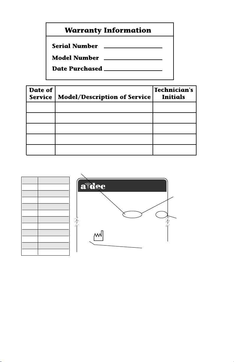
1999
2601 CRESTVIEW DRIVE
NEWBERG, OREGON 97132 USA
Tele: (44) 24 7635 0901
SN: J828287
MADE
IN USA
SERIAL
NUMBER
REF: 2122
MODEL
NUMBER
YEAR MANUFACTURED
Serial Number Identification
Performer Equipment:
• Delivery System: On the bottom of the control head.
• Cuspidor: Underneath the cuspidor, on the post.
• Assistant’s Instrumentation: Underneath the assistant’s
instrumentation module, on the post.
• Light: On the light post, near the mounting end.
• Chair: On the upper structure, under the seat upholstery
For service information contact your local authorized A-dec dealer.
Check with local codes and A.D.A. (Americans with Disabilities
Act) requirements for Installation of this product.
Page 3
A-dec warrants its products and A-dec/W&H Synea
handpieces against defects in material or workmanship
for one year from time of delivery. All other handpiece
instrumentation has a warranty period of six months.
A-dec’s sole obligation under the warranty is to provide
parts for the repair, or at its option, to provide the
replacement product (excluding labor). The buyer shall
have no other remedy. (All special, incidental, and
coincidental damages are excluded.) Written notice of
breach of warranty must be given to A-dec within the
warranty period. The warranty does not cover damage
resulting from improper installation or maintenance,
accident or misuse.The warranty does not cover damage resulting from the use of cleaning, disinfecting or
sterilization chemicals and processes. The warranty also
does not cover light bulbs. Failure to follow instructions
provided in A-dec’s Operation and Maintenance
Instructions (Owner’s Guide) may void the warranty.
Warranty
NO OTHER WARRANTIES AS TO
MERCHANTABILITY OR OTHERWISE ARE MADE.
All product names used in this document are trademarks or
registered trademarks of their respective holders.
Printed in U.S.A. • Copyright © 2000 • All Rights Reserved
Page 4
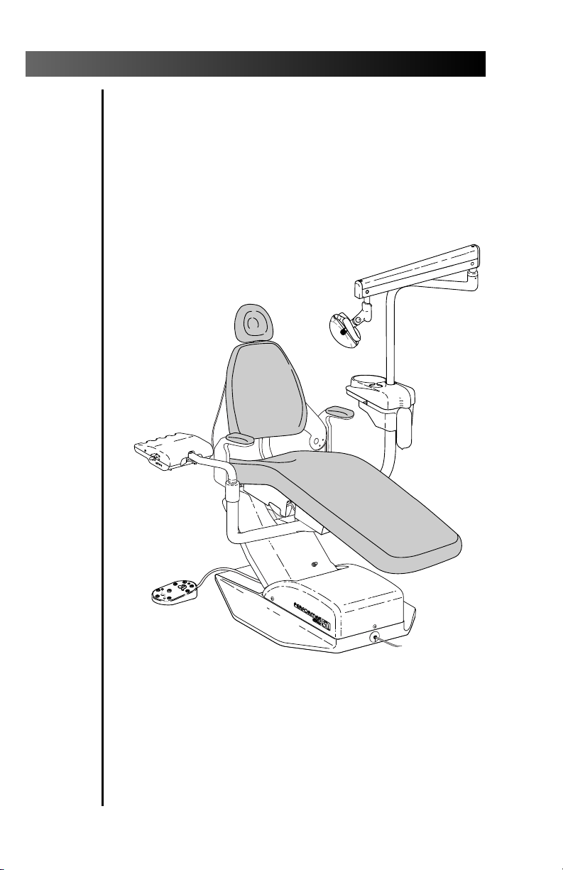
Performer
Serial number location, service information,
and warranty information are located on the
inside front cover and front page.
Performer III Chair
Page 5

CONTENTS
Performer III Chair
Back Positioning................................................ 1
Seat Positioning................................................. 1
Programming Positions 0, 1, or 2 ..................... 2
Chair LED .......................................................... 3
Chair Stop Plate ................................................ 4
Headrest Positioning......................................... 5
Headrest Glide Bar Tension Adjustment .......... 5
Upholstery Replacement .................................. 6
Double-Articulating Headrest Upholstery.... 6
Backrest Upholstery/Armrest Caps ............ 6
Narrow Backrest Upholstery with Slings.... 7
Seat/Toeboard Upholstery .......................... 7
Performer Handpiece Control
Master On/Off Toggle ....................................... 8
Foot Control, Wet/Dry Toggle ........................... 8
Drive Air Adjustment........................................ 9
Coolant Air Adjustment ................................. 10
Coolant Water Adjustment ............................ 10
Handpiece Tubing Flush................................. 11
Handpiece Oil Collector, Cleaning................. 12
Handpiece Control Adjustments.................... 12
Control Head Height Adjustment ............ 12
Control Head Positioning ......................... 12
Pivot Point Tension Adjustment ............... 13
A-dec Autoclavable Syringe
Using the Autoclavable Syringe ..................... 14
Syringe Flow Adjustments .............................. 14
Performer Cuspidor
Cup Fill ............................................................ 15
Bowl Rinse ....................................................... 15
Cuspidor Bowl Rinse Flow Adjustment .......... 16
Performer
Page 6

Performer
CONTENTS
Assistant’s Instrumentation
Autoclavable HVE........................................... 17
Autoclavable Saliva Ejector............................ 17
HVE Screen ...................................................... 17
Performer Assistant’s Arm
(Optional for Performer III Chair ONLY.)
Holder Tension Adjustment............................ 18
Swivel Tension Adjustment............................. 18
Performer Accessory Tray Holder
(Optional for Performer III Chair ONLY.)
Tray Holder Height Adjustment ..................... 19
Swivel Tension Adjustment............................. 19
Performer Dental Light
Dental Light On/Off Toggle............................ 20
Dental Light Intensity Switch ......................... 20
Light Head Positioning ................................... 20
Dental Light Bulb Replacement ..................... 21
Light Head Pivot Adjustments........................ 21
Floor Box
Air Filter Element Replacement...................... 22
Water Screen Replacement ............................. 22
Accessories
Bitewing Viewer .............................................. 23
Bitewing Viewer Bulb Replacement ............... 23
80 Watt Power Supply..................................... 23
Fiber-Optic Bulb Replacement........................ 24
Dual HVE......................................................... 24
General Information
Adjustments and Specifications ..................... 25
Maintenance................................................... 26
Safety Considerations for
Accessory Equipment................................ 26
Identification of Symbols................................ 27
Classification of Equipment
(EN 60601-1)
....... 27
Page 7
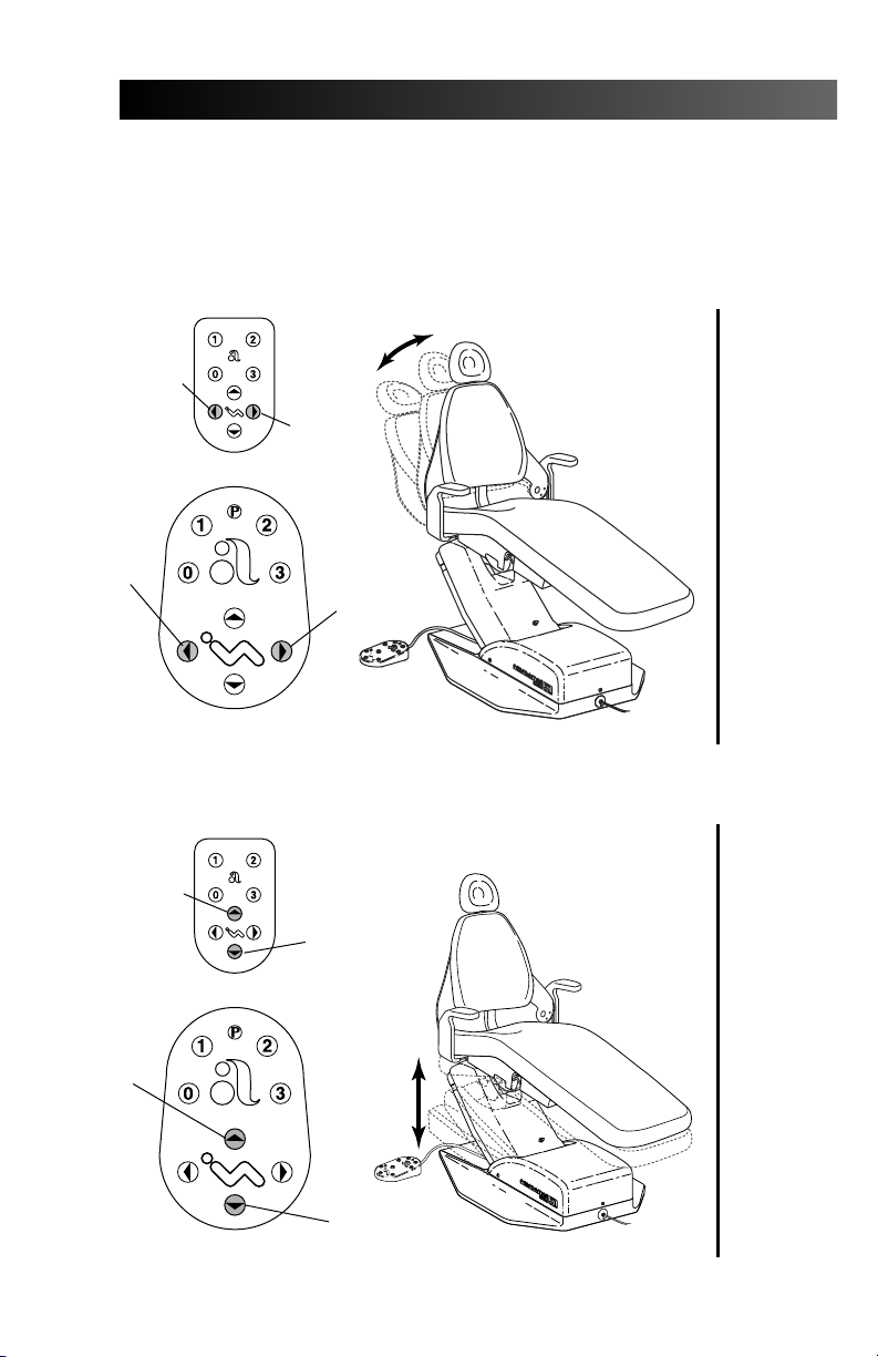
CHAIR
BACK
DOWN
CHAIR
BACK
DOWN
Performer
PERFORMER III CHAIR
Back Positioning
CHAIR
BACK UP
TOUCH PAD
CHAIR
BACK UP
FOOTSWITCH
CHAIR
LIFT UP
CHAIR
LIFT
UP
Seat Positioning
CHAIR
LIFT DOWN
TOUCH PAD
CHAIR
LIFT DOWN
FOOTSWITCH
1
Page 8
Performer
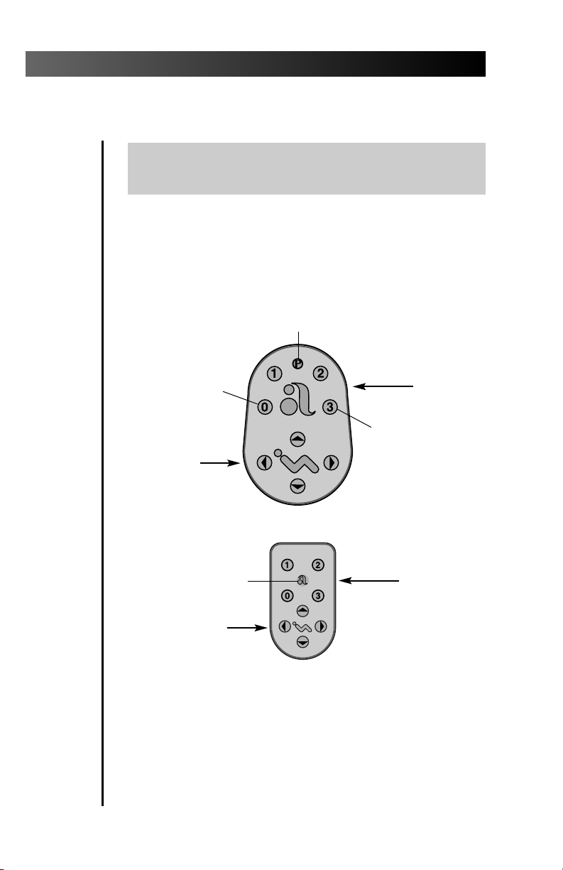
Programming Positions 0, 1, or 2
NOTE
To stop the chair at any point, push any button on
the footswitch or touch pad.
• Move the chair to the desired operating position.
• Press the program button. A tone will sound.
• Press the programmable position button for the
desired setting (0, 1, or 2) within 4 seconds.
• A tone will sound 3 times confirming the position
has been reprogrammed.
PROGRAM BUTTON
PRE-PROGRAMMED
FOR ENTRY/EXIT
MANUAL
POSITION
BUTTONS
PROGRAMMABLE
POSITION
BUTTONS
CUSPIDOR/RETURN
(FACTORY SET)
Chair Footswitch
PROGRAMMABLE
PROGRAM BUTTON
MANUAL
POSITION
BUTTONS
POSITION
BUTTONS
Chair Touch Pad
Position 3 is factory set in the Cuspidor/Return mode.
Pressing the position 3 button moves the chair back up
allowing patient access to the Cuspidor. Pressing the
position 3 button a second time returns the patient to
the previous operating position.
Contact an authorized A-dec Dealer to have Position 3 reconfigured to a third Pre-Position or as a last position recall.
2
Page 9
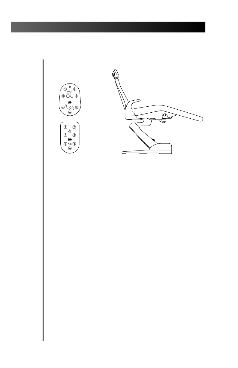
The chair LED indicates the status of the chair:
ON: Normal operation.
SLOW BLINK: The cuspidor or stop plate limit
switches have been activated. Remove any
obstructing object.
CHAIR LED
Performer
Chair LED
3
Page 10
Performer
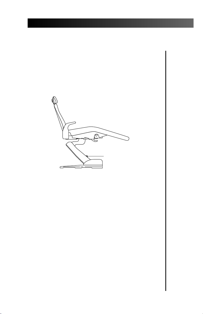
Chair Stop Plate
The chair stop plate stops the chair immediately
when any part of it is pressed. Should anything
inadvertently become lodged under the chair,
press Base UP on the footswitch or touch pad to
raise the chair so the object can be removed. As
long as pressure is applied to the stop plate, the
chair base will not go down any further.
CHAIR STOP
PLATE
4
Page 11
Performer
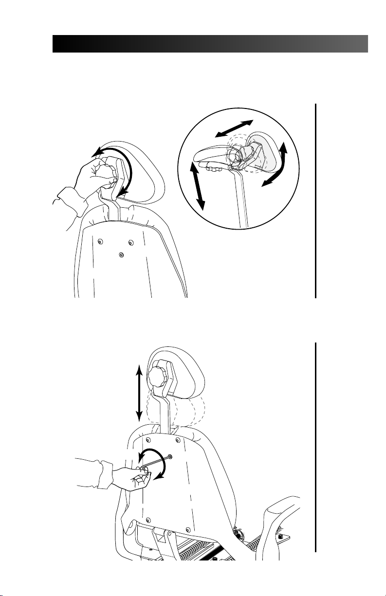
Headrest Positioning
Headrest Glide Bar Tension Adjustment
DECREASE
INCREASE
5
Page 12

Performer
Upholstery Replacement
Double-Articulating Headrest Upholstery
Backrest Upholstery/Armrest Caps
6
Page 13

Performer
Narrow Backrest Upholstery with Slings
MOUNTING
SCREWS
Seat/Toeboard Upholstery
7
Page 14

Performer
PERFORMER HANDPIECE CONTROL
Master On/Off Toggle
Foot Control, Wet/Dry Toggle
8
Page 15

Performer
Drive Air Adjustment
2
kg/cm
psi
1
10 20
23
30
40
50 60
4
NOTE
The drive air control must be adjusted to meet
the handpiece manufacturer’s drive air pressure
specification. Refer to the documentation that
came with your handpiece for drive air pressure.
9
Page 16

Performer
Coolant Air Adjustment
Coolant Water Adjustment
10
Page 17

Handpiece Tubing Flush
The handpiece tubing flush system flushes
more water through the tubings in less time
than is normally possible when operating the
foot control only. The handpieces should not be
connected when flushing the tubings.
Performer
How Often Should the Handpiece Tubings be Flushed?
After each patient:
Flush the tubings for about 20–30 seconds.
At the beginning of each day:
Flush the tubings for 2–3 minutes.
11
Page 18

Performer
Handpiece Oil Collector, Cleaning
Change the 2" (50mm) square gauze pad once a week.
Handpiece Control Adjustments
Control Head Height Adjustment
Control Head Positioning
12
Page 19

Performer
Pivot Point Tension Adjustment
FRONT MOUNT
BACK MOUNT
13
Page 20

Performer
A-DEC AUTOCLAVABLE SYRINGE
Using the Autoclavable Syringe
Syringe Flow Adjustments
14
Page 21

Performer
PERFORMER CUSPIDOR
Cup Fill
Bowl Rinse
15
Page 22

Performer
Cuspidor Bowl Rinse Flow Adjustment
DECREASE FLOW
INCREASE FLOW
16
LOCATED IN THE FLOOR BOX.
Page 23

Performer
ASSISTANT’S INSTRUMENTATION
Autoclavable HVE
Autoclavable Saliva Ejector
HVE Screen
17
Page 24

Performer
PERFORMER ASSISTANT’S ARM
(Option for Performer III Chair ONLY)
Holder Tension Adjustment
HOLDER TENSION
ADJUSTMENT SETSCREWS
Swivel Tension Adjustment
REMOVE SEAT
UPHOLSTERY
18
5/16"
HEX KEY
SWIVEL TENSION
ADJUSTMENT BOLT
BACKREST IN NEAR
FULL DOWN POSITION.
Page 25

Performer
PERFORMER ACCESSORY TRAY HOLDER
(Option for Performer III Chair ONLY)
Tray Holder Height Adjustment
TRAY HOLDER
TRAY HOLDER ARM
HEIGHT ADJUSTMENT RING
1.Lift the tray holder to access the height adjustment ring.
2.Slide the height adjustment ring to desired position.
3.Lower the tray holder onto the arm.
Swivel Tension Adjustment
ACCESSORY
TRAY
HOLDER
ARM
5/16"
HEX KEY
REMOVE SEAT
UPHOLSTERY
19
Page 26

Performer
PERFORMER DENTAL LIGHT
Dental Light On/Off Toggle
Dental Light Intensity Switch
Light Head Positioning
20
Page 27

Performer
Dental Light Bulb Replacement
Light Head Pivot Adjustment
21
Page 28

Performer
FLOOR BOX
Air Filter Element Replacement
MANUAL AIR
SHUTOFF VALVE
(Turn completely OFF
when replacing the
air filter element.)
Water Screen Replacement
WATER
REGULATOR
(black body)
22
WATER SCREEN
(water shutoff valve only)
MANUAL WATER
SHUTOFF VALVE
(Turn completely OFF
when replacing the
water filter screen.)
COMPRESSION
NUT
Page 29

Performer
ACCESSORIES
Bitewing Viewer
Bitewing Viewer Bulb Replacement
80 Watt Power Supply
NOTE
No cleaning or maintenance required. If the floor
box has an indicator light, it will illuminate when
the power supply is plugged in.
23
Page 30

Performer
Fiber-Optic Bulb Replacement
Dual HVE
24
Page 31

GENERAL INFORMATION
Adjustments and Specifications
Performer III Chair......................................page 1
Headrest Positioning...................................page 5
Headrest Glide Bar Tension Adjustment....page 5
Drive Air Adjustment..................................page 9
Coolant Air Adjustment .............................page 0
Coolant Water Adjustment ........................page 0
Control Head Height Adjustment ..............page 12
Control Head Positioning...........................page 13
Pivot Point Tension Adjustments................page 13
Using the Autoclavable Syringe.................page 14
Syringe Flow Adjustments ..........................page 14
Cuspidor Bowl Rinse Flow Adjustment ......page 16
Dental Light Intensity Switch.....................page 20
Light Head Positioning...............................page 21
Light Head Pivot Adjustments....................page 21
Minimum air, water, and vacuum service
requirements for proper unit operation:
L
Air: 2.50 cfm (70.80
Water: 1.50 gpm (5.68
Vacuum: 12 cfm (339.84 L/min) at 8 inches
(27 kPa) of mercury.
/min) at 80 psi (551 kPa).
L
/min) at 40 psi (276 kPa).
Performer
Maximum weight specifications:
Maximum control head weight is 55 lbs. (30 kg).
Maximum cuspidor and dental light weight is
27 lbs. (12.25 kg).
Maximum Tray Holder (optional) weight is
12 lbs. (5.44 kg).
Weight of optional scaler: 2 lbs. (.91 kg).
Chair Capacity:
Patient Load: 300 lbs (135 kg) maximum.
Accessory Load: 130 lbs. (59 kg) maximum.
25
Page 32

Performer
Maintenance
Handpiece Tubing Flush...........................page 11
Oil Collector, Cleaning...............................page 12
HVE Screen ..................................................page 17
Dental Light Bulb Replacement.................page 21
Air & Water Filter Element Replacement ......page 22
Bitewing Viewer Bulb Replacement ...........page 23
80 Watt Power Supply.................................page 23
Fiber-Optic Bulb Replacement ...................page 24
Also refer to the following Owner’s Guides for
more maintenance information:
Autoclavable Syringe ............................85.0680.00
Equipment Asepsis ................................85.0696.00
Maintenance Parts ................................85.2634.00
Self-contained Water System ................85.0675.00
Safety Considerations for
Accessory Equipment
The use of accessory equipment not complying
with the equivalent safety requirements of this
equipment may lead to a reduced level of safety
of the resulting system.
Consideration relating to the use of accessory
equipment shall include:
Evidence that Safety Certification of the accessory
equipment has been performed in accordance to
the appropriate IEC 601 and IEC 601-1 Harmonized
National Standards.
26
Page 33

¤
Identification of Symbols
Recognized by Underwriters Laboratories Inc. ® with respect to
electric shock, fire and mechanical hazards only in accordance
with UL 2601-1. Recognized with respect to electric shock, fire,
mechanical and other specified hazards only in accordance with
CAN/CSA C22.2, No. 601.1.
UL listed to US (UL 544) and Canadian (CAN/CSA C22.2, No.
125) safety standards.
LISTED
Classified by Underwriters Laboratories Inc. ® with respect to electric shock, fire and mechanical hazards only in accordance with
UL 2601-1. Classified with respect to electric shock, fire, mechanical and other specified hazards only in accordance with
CAN/CSA C22.2, No. 601.1.
Performer
Conforms to European Directives
Protective earth (ground).
Functional earth (ground).
Attention, consult accompanying documents.
!
TYPE B APPLIED PART.
CLASS II EQUIPMENT.
(refer to Declaration Statement)
Classification of Equipment (EN 60601-1)
Type of Shock Protection:
CLASS I EQUIPMENT
(Dental Chairs, Dental Lights, & Power Supplies)
CLASS II EQUIPMENT
(Chair, Wall, & Cart Mounted Delivery Systems)
Degree of Shock Protection:
TYPE B APPLIED PART (All products)
(Degree of protection against water ingress:
ORDINARY EQUIPMENT (All products)
Mode of Operation
CONTINUOUS OPERATION
(All models except Dental Chairs)
Mode of Operation
CONTINUOUS OPERATION WITH
INTERMITTENT LOADING (Dental Chairs)
27
Page 34

Performer
28
Page 35

Performer
29
Page 36

2601 Crestview Drive
Newberg, Oregon 97132 U.S.A.
Telephone 1-800-547-1883
(503) 538-7478
Fax (503) 538-0276
Designated Representative’s Address:
A-dec Dental U.K., Ltd.
Austin House
11 Liberty Way
Attleborough Fields Industrial Estate,
Nuneaton, Warwickshire,
England CV11 6RZ
Telephone: 0800-ADECUK (233285) Within UK
00 44 24 7635 0901 Outside UK
Fax: 00 44 24 7634 5106
Designated Representative’s Address:
A-dec Australia
41-43 Bowden Street
Alexandria, N.S.W. 2015, Australia
Telephone: (61) 1.800.225010 within Australia
00612-9699-4600 outside Australia
Fax: 00612-9699-4700
85.2638.00
2000-03 Rev C
(1968.07)
Made with 50% waste paper
Printed in USA.
Copyright © 2000,
All Rights Reserved.
 Loading...