

Page 1

85.0812.00, 2003 i
Contents
Identifying A-dec Tubing . . . . . . . . . . . . . . . . . . . . . . . . . . . . . . . . .PR-2
Identifying Tubing Functions . . . . . . . . . . . . . . . . . . . . . . . . . . . . .PR-3
Locating Serial/Model Number Labels . . . . . . . . . . . . . . . . . . . . .PR-7
Troubleshooting Performer I Chair . . . . . . . . . . . . . . . . . . . . . . . . .PR-13
Troubleshooting Performer II Chair . . . . . . . . . . . . . . . . . . . . . . . .PR-19
Adjusting the Hydraulic Manifold . . . . . . . . . . . . . . . . . . . . . . . . .PR-25
Installing a Solenoid . . . . . . . . . . . . . . . . . . . . . . . . . . . . . . . . . . . . .PR-26
Correcting Hydrostatic Lock . . . . . . . . . . . . . . . . . . . . . . . . . . . . . .PR-28
Testing and Programming the Circuit Board . . . . . . . . . . . . . . . .PR-34
Testing Factory Defaults . . . . . . . . . . . . . . . . . . . . . . . . . . . . . . . . . .PR-35
Identifying New Features . . . . . . . . . . . . . . . . . . . . . . . . . . . . . . . . .PR-38
Using the Headrest . . . . . . . . . . . . . . . . . . . . . . . . . . . . . . . . . . . . . .PR-44
Removing the Helical Drive Shaft . . . . . . . . . . . . . . . . . . . . . . . . .PR-47
Adjusting the Base Positioning Potentiometer . . . . . . . . . . . . . . .PR-49
Adjusting the Base Up Limit Switch . . . . . . . . . . . . . . . . . . . . . . .PR-50
Programming the Chair . . . . . . . . . . . . . . . . . . . . . . . . . . . . . . . . . .PR-51
Programming Function 3 . . . . . . . . . . . . . . . . . . . . . . . . . . . . . . . . .PR-52
Troubleshooting Foot Controls . . . . . . . . . . . . . . . . . . . . . . . . . . . .PR-73
Troubleshooting the Control Block . . . . . . . . . . . . . . . . . . . . . . . . .PR-79
Troubleshooting Syringes . . . . . . . . . . . . . . . . . . . . . . . . . . . . . . . . .PR-83
Working with the Holder Valve Assembly . . . . . . . . . . . . . . . . . .PR-84
Activating the Holder Valve . . . . . . . . . . . . . . . . . . . . . . . . . . . . . .PR-87
Adjusting the Accessory Tray Holder Height . . . . . . . . . . . . . . . .PR-88
Adjusting the Accessory Tray Holder Arm Tension . . . . . . . . . .PR-88
Adjusting the Light Head Vertical Tension . . . . . . . . . . . . . . . . . .PR-91
Adjusting the Light Head Horizontal Tension . . . . . . . . . . . . . . .PR-91
Focusing the Light . . . . . . . . . . . . . . . . . . . . . . . . . . . . . . . . . . . . . . .PR-91
Adjusting the Flexarm . . . . . . . . . . . . . . . . . . . . . . . . . . . . . . . . . . .PR-92
Troubleshooting Dental Lights . . . . . . . . . . . . . . . . . . . . . . . . . . . .PR-93
Troubleshooting Cuspidors . . . . . . . . . . . . . . . . . . . . . . . . . . . . . . .PR-99
Troubleshooting Air Vacuum Generator . . . . . . . . . . . . . . . . . . . .PR-103
Troubleshooting Water Saliva Ejectors . . . . . . . . . . . . . . . . . . . . . .PR-111
Adjusting Holder Tension . . . . . . . . . . . . . . . . . . . . . . . . . . . . . . . .PR-120
Adjusting Tension on the Assistant’s Arm . . . . . . . . . . . . . . . . . .PR-120
Troubleshooting Assistant’s Instrumentation . . . . . . . . . . . . . . . .PR-121
Page 2

85.0812.00, 2003 PR-1
Performer Overview
This section provides descriptions, service, maintenance, adjustment, and troubleshooting detail on
the Performer product line.
Page 3
85.0812.00, 2003 PR-2
Performer Tubing
Identifying
A-dec Tubing
Using
Suggested Fittings
Identifying Detail
This section identifies the tubing type
used when servicing A-dec products.
Allow adequate length when installing
to avoid crimping or bending of
tubing. The use of the appropriate
tools can improve the ease of tubing
installation or replacement.
Unit-clamps or tubing sleeves must be
used to ensure a good seal and to
prevent tubing from coming off barbs.
For 1/4" polyurethane tubing,
use 1/4" barbs with sleeves and 1/4"
Poly-Flo fittings.
For 3/8" Polyurethane tubing,
use 3/8" Poly-Flo fittings.
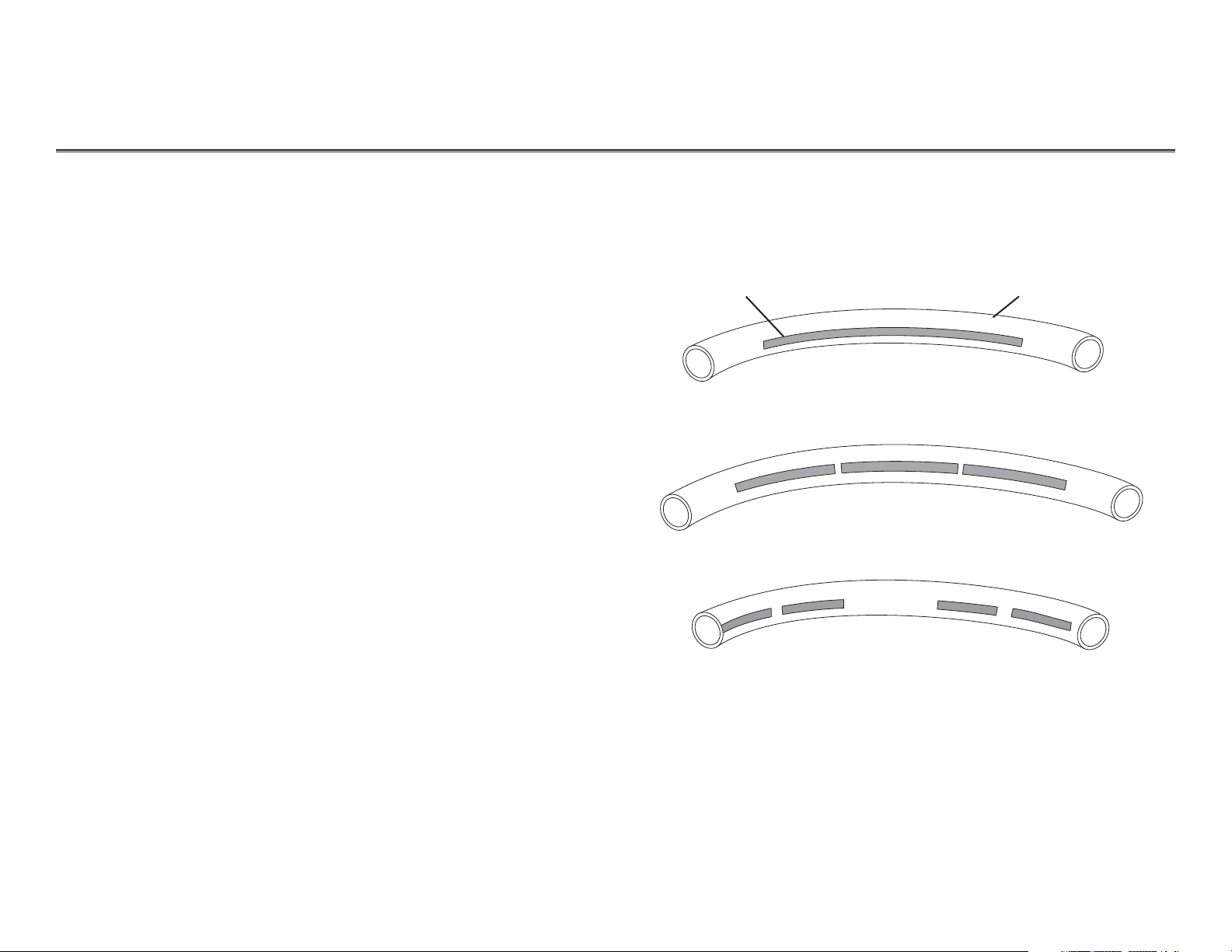
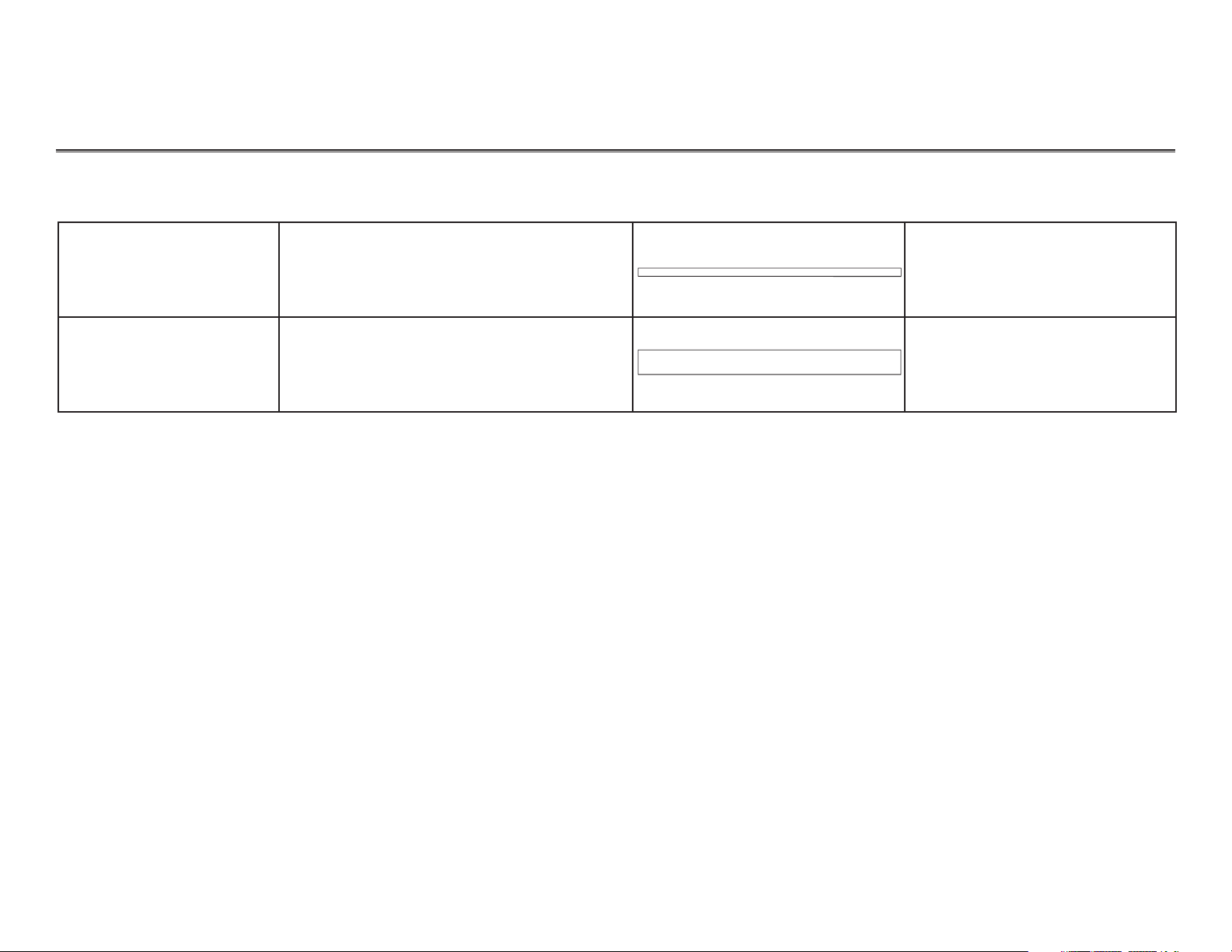
When identifying tubing, the body
color of the tubing is the “tubing
color”. The line and/or the A-dec
name printed on the tubing are the
“tracer markings”. These two details
will identify the type of tubing you
will need and its use.
Color of tubing
Tracer marking
Tubing with stripe tracer
Tubing with long dash tracer
Tubing with short dash tracer
Tubing Identification Details
A-DEC
A-DEC
A-DEC
A-DEC
A-DEC
Page 4
85.0812.00, 2003 PR-3
Performer Tubing
Tubing Function
Description Part NumberTubing Color
When installing or replacing tubing, allow enough length to avoid crimping or bending. Unit-clamps or
tubing sleeves must be used to ensure a good seal and to prevent tubing from coming off barbs.
The following table lists the different types of tubing and its function.
Identifying
Tubing Functions
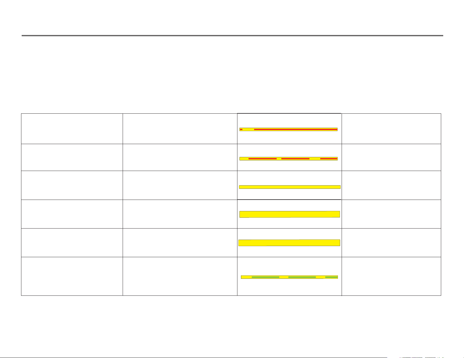
Unregulated Air Continuous, filtered, unregulated air
— 1/8" OD from the air
regulator to On/Off toggle
036.013.03
Pilot Air Filtered unregulated air controlled by
Master On/Off toggle —1/8" OD
036.009.04
Regulated Air Supply Continuous, filtered, regulated air
—1/8" OD
036.003.03
Regulated Air Supply Regulated air — 3/8" OD 036.103.03
Regulated Air Supply Regulated air — 3/8" OD 036.031.02
Regulated Air (40 psi) Regulated air at 40 psi to pressurize
the water bottle — 1/8" OD
036.044.03
A-DEC
A-DEC A-DEC
A-DEC
A-DEC
A-DEC
A-DEC
Page 5
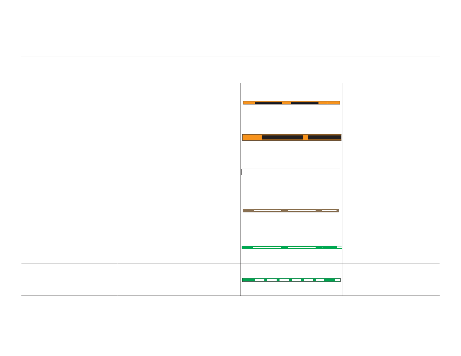
036.006.03
Signal air/air coolant from foot control,
signal air for cuspidor cup filler and
vacuum actuator — 1/8" OD
Signal Air, Coolant Air
85.0812.00, 2003 PR-4
Performer Tubing
Tubing Function
Description
Part Number
Tubing Color
Drive Air Drive air for pressure gauge — 1/8" OD 036.010.03
Drive Air Drive air for foot control — 1/4" OD 036.052.03
Drive Air Handpiece drive air (clear) — 1/4" OD 036.066.03
Chip Blower Air Air for chip blower — 1/8" OD 036.014.02
Signal Air, Water Coolant Signal air/water coolant from foot
control, signal air for cuspidor bowl rinse
— 1/8" OD Signal
036.018.03
A-DEC A-DEC
A-DEC
A-DEC A-DEC
A-DEC
A-DEC A-DEC
A-DEC
A-DEC
Page 6
85.0812.00, 2003 PR-5
Performer Tubing
Tubing Function
Description
Part Number
Tubing Color
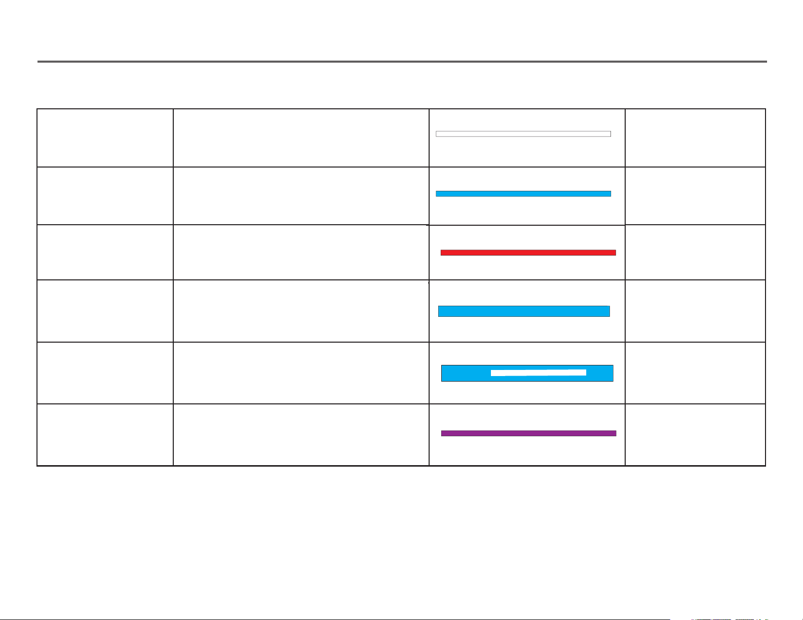
Signal Air, Coolant Water Signal air (clear) from foot control relay to
wet/dry toggle — 1/8" OD
024.015.04
Water Supply Coolant water supply, handpiece water
— 1/8" OD
036.004.03
Oral Cavity Water Oral cavity water — 1/8" OD 036.005.03
Water Supply Regulated water, water to bowl rinse
— 1/4" OD
036.053.03
Water Supply
Unregulated water
— 3/8" OD
036.033.02
Return Water Return water, tank water heater, water to gravity
drain drip tube from syringes — 1/8" OD
036.011.03
A-DEC A-DEC
A-DEC A-DEC
A-DEC
A-DEC A-DEC
Page 7
85.0812.00, 2003 PR-6
Performer Tubing
Tubing Function
Description Part NumberTubing Color
Miscellaneous Miscellaneous line (white) for use with
A-dec authorized accessories — 1/8" OD
036.019.03
Hydraulic System Supply Low pressure hydraulic system supply for
chair (clear) — 3/8" OD
036.035.00
A-DEC A-DEC
A-DEC A-DEC
Page 8
85.0812.00, 2003 PR-7
Performer Serial/Model Number Label
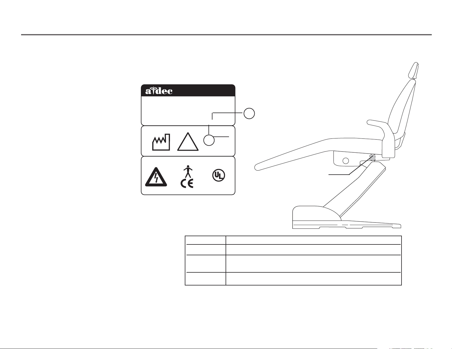
Locating Serial/Model
Number Labels
Item # Description
1 Month of manufacture
The first letter of the serial number indicates the month
the product was manufactured; e.g., A is January.
2 Last digit of the year manufacture
1
2
Serial/model number
tag (at base of arm)
The serial/model number label identifies the chair model and the month and year in
which the chair was manufactured. This label is located on the underside of the righthand arm rest support.
2601 CRESTVIEW DRIVE
®
BERG, OREGON 97132 USA
NEW
Designated EU Representative: A-dec Dental U.K., Ltd.
Austin House, 11 Liberty Way, Attleborough Fields,
Nuneaton, Warwickshire, England CV 116RZ
DENTAL
CHAIR
MADE IN
USA
2001
CAUTION!
Tele: (44) 1203-350901
REF: 8000
!
DENTAL CHAIR
LABEL P/N: 051.515.02 REV L
S/N: J167856
INPUTS
-
120 V
10 AMPS MAX
50-60 Hz
C
®
LISTE
D
15VJ
U
S
Page 9
85.0812.00, 2003 PR-8
Performer Performer I
WARNING.
DO NOT
USE THE
HEADREST
IF THE
LINE IS
VISABLE.
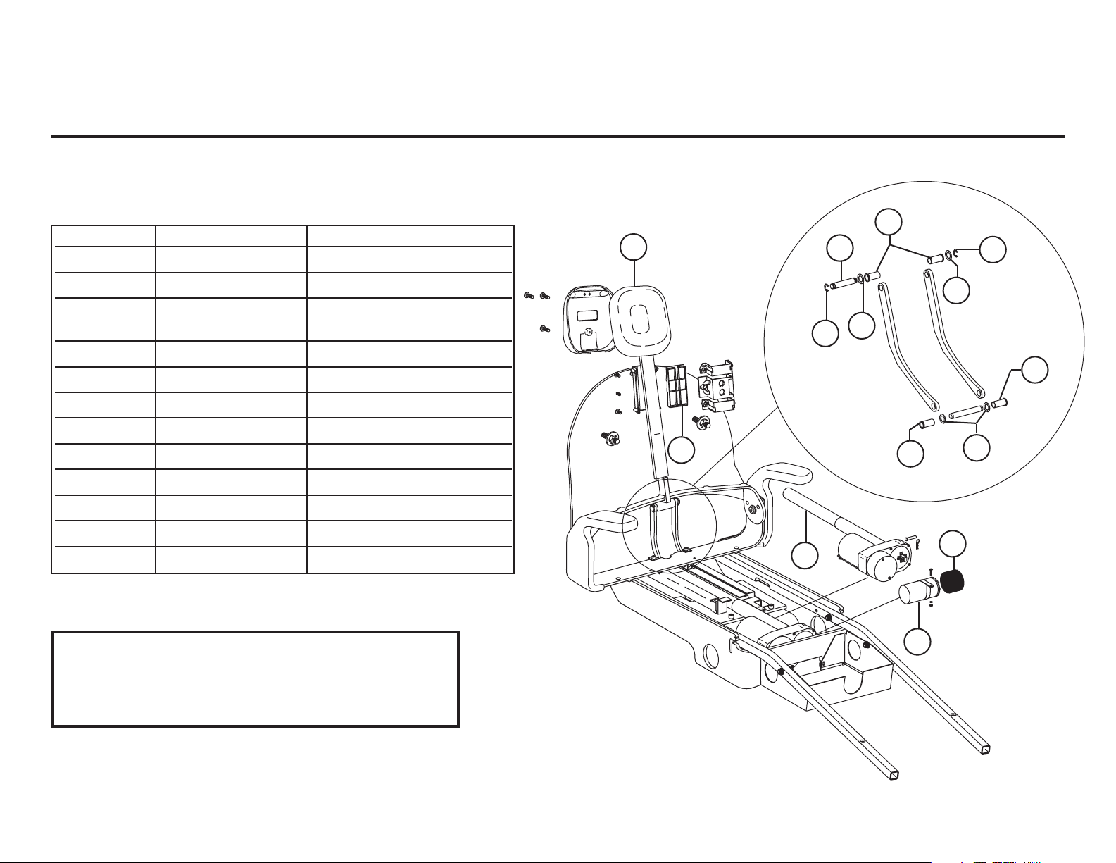
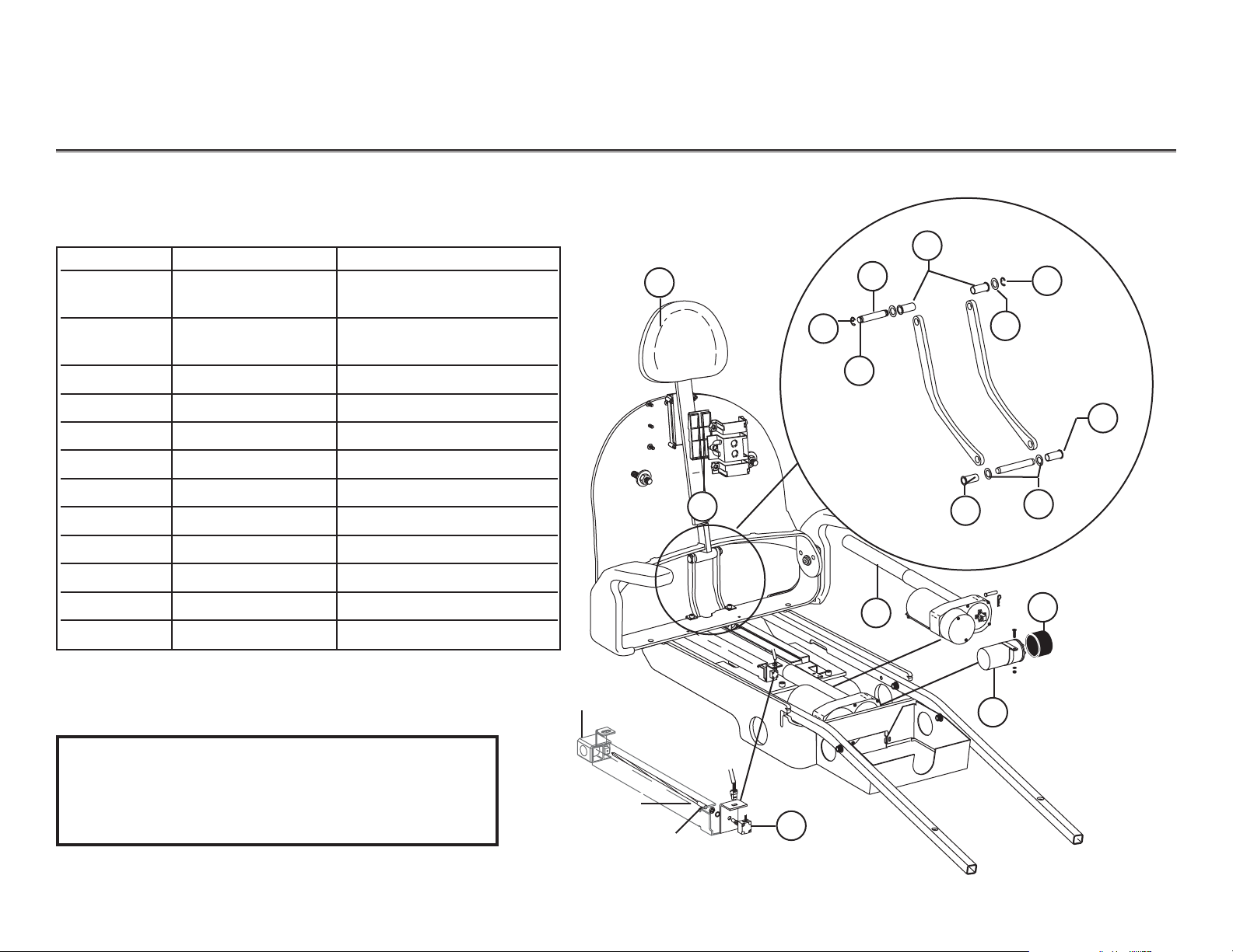
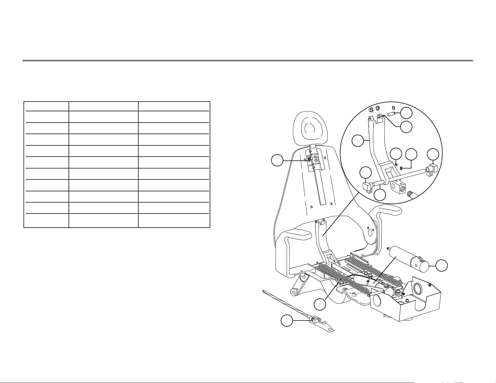
Item # Part Number Description
1 (Obsolete) Single articulating headrest
61.2116.XX Double articulating headrest
2 61.1569.00 Wear pad, sliding
wedge molded
3 61.2409.00 115V tilt actuator
3 61.2410.00 230V tilt actuator
4. 041.529.00 Capacitor boot
5 90.1035.00 115V tilt actuator capacitor
90.1036.00 230V tilt actuator capacitor
6 61.2181.00 Bearing, flanged
7 004.035.00 Washer, flat, nylatron
8 010.040.01 E-ring, retaining
10 61.2425.00 Pivot pin, back link
Performer I Upper Structure
1
2
8
7
6
4
5
3
7
8
9
6
7
6
WARNING
High voltages are present at motor and limit switch
connections. Unplug the chair before servicing. Failure
to do so could result in serious injury.
WARNING.
DO NOT
USE THE
HEADREST
IF THE
LINE IS
VISABLE.
Page 10
85.0812.00, 2003 PR-9
Performer Performer I
Performer I Base Structure
TM
TM
TM
TM
TM
1
3
4
2
6
8
7
NOTE: If the chair limit switch bracket assembly is not located in the
upper lift arm of the chair, it will need to be replaced with a
base limit switch kit, P/N 90.1000.00.
5
Item # Part Number Description
1 041.583.00 240V base capacitor
(after June 1998)
— 041.517.00 240V base capacitor
(before June 1998)
— 041.504.00 440V base capacitor
2 041.529.00 115V capacitor boot
3 61.2469.00 115V base actuator
— 61.2470.00 230V actuator
4 61.2483.00 Joystick chair control
5 90.1000.00 Base limit switch kit
6 044.183.00 Base down, shutoff switch
7 044.184.00 Base up limit switch (Red)
8 044.184.00 Base down limit switch (Black)
T
T
M
M
T
M
T
T
M
M
Page 11
85.0812.00, 2003
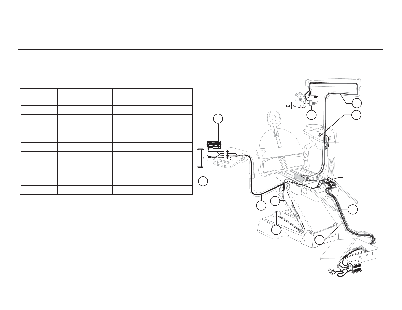
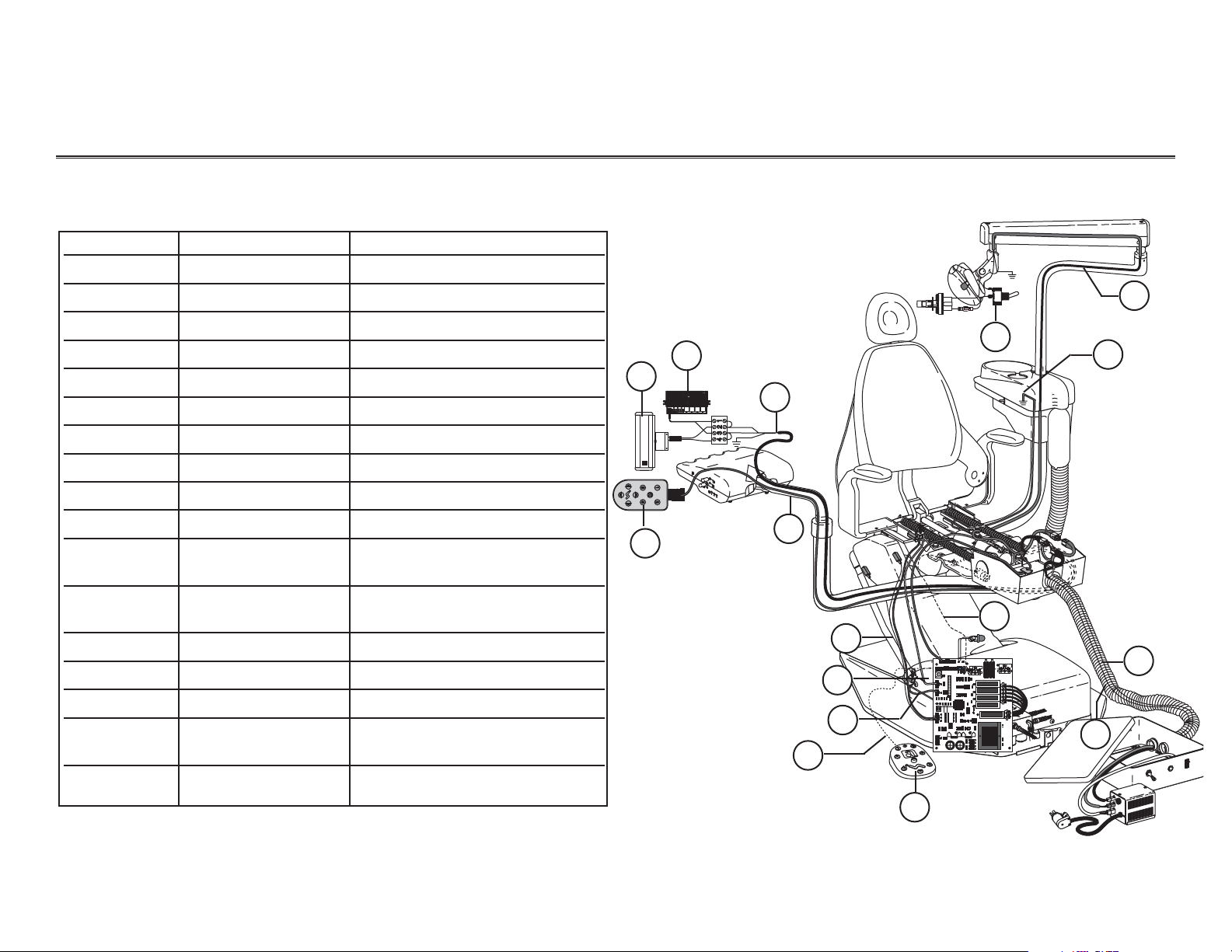
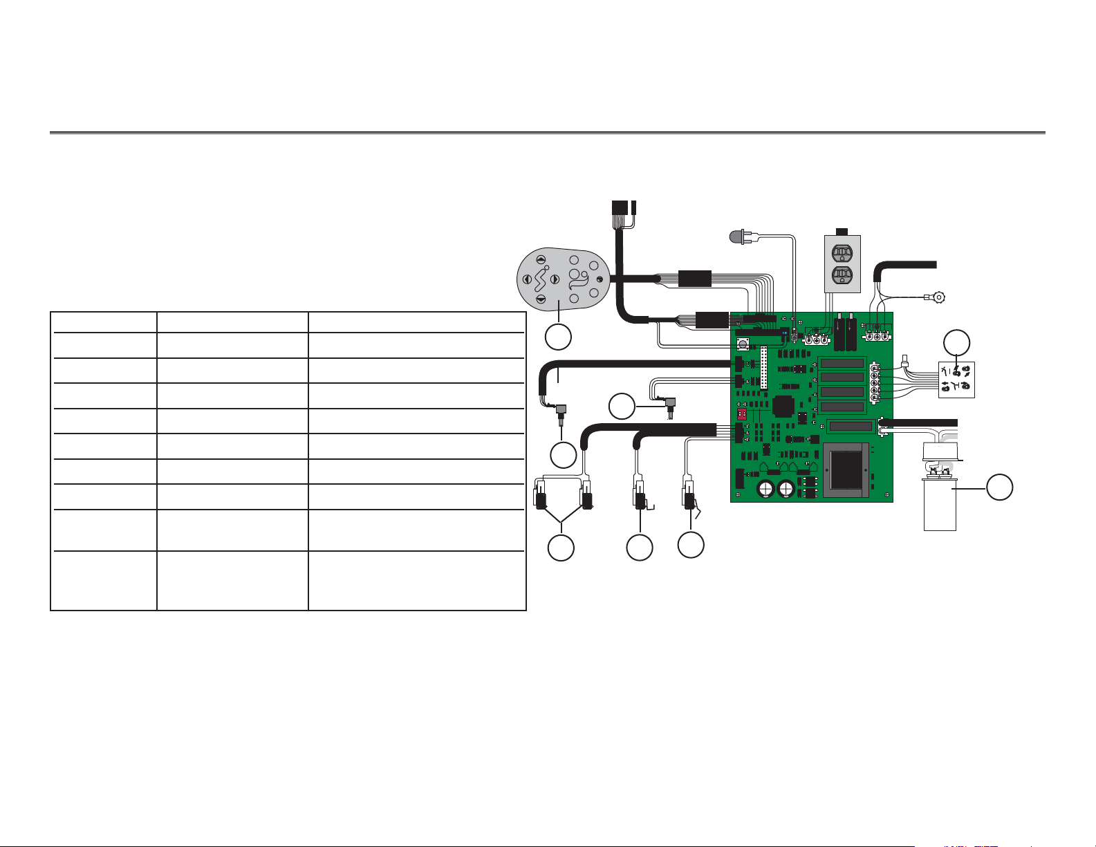
Performer Performer I Electrical Flow Diagram
INTRA OR AL
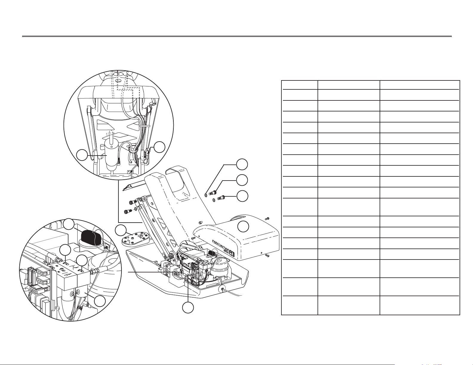
Item # Part Number Description
1 76.1005.00 Intra-oral light source kit
2 76.8000.00 Bitewing x-ray viewer
3 35.1673.00 Cable assembly
4 61.2582.00 Wire harness assembly
5 61.2483.00 Joystick, auto exit
6 35.1567.00 Cable assembly
7 28.1244.00 Cable assembly, dental light
8 41.1444.00 Ground wire assembly
(after April 1999)
9 90.1054.00 Cable assembly
10 90.1039.00 On/Off switch
1
2
3
4
5
6
7
8
9
10
Before January 1996,
dental light cable
assembly connected in
cuspidor housing.
After January 1996,
dental light cable
assembly connected
in the junction box.
Performer I Electronics
PR-10
ADJUST ONLY
PN 34-0064-00
WHEN BRIGHT
DANGER
INTRA ORAL
LIGHT SOURCE
2.9 - 4.25VDC .8AMP
POWER
24V
BRIGHT
/DC
AC
4321
Page 12
85.0812.00, 2003 PR-11
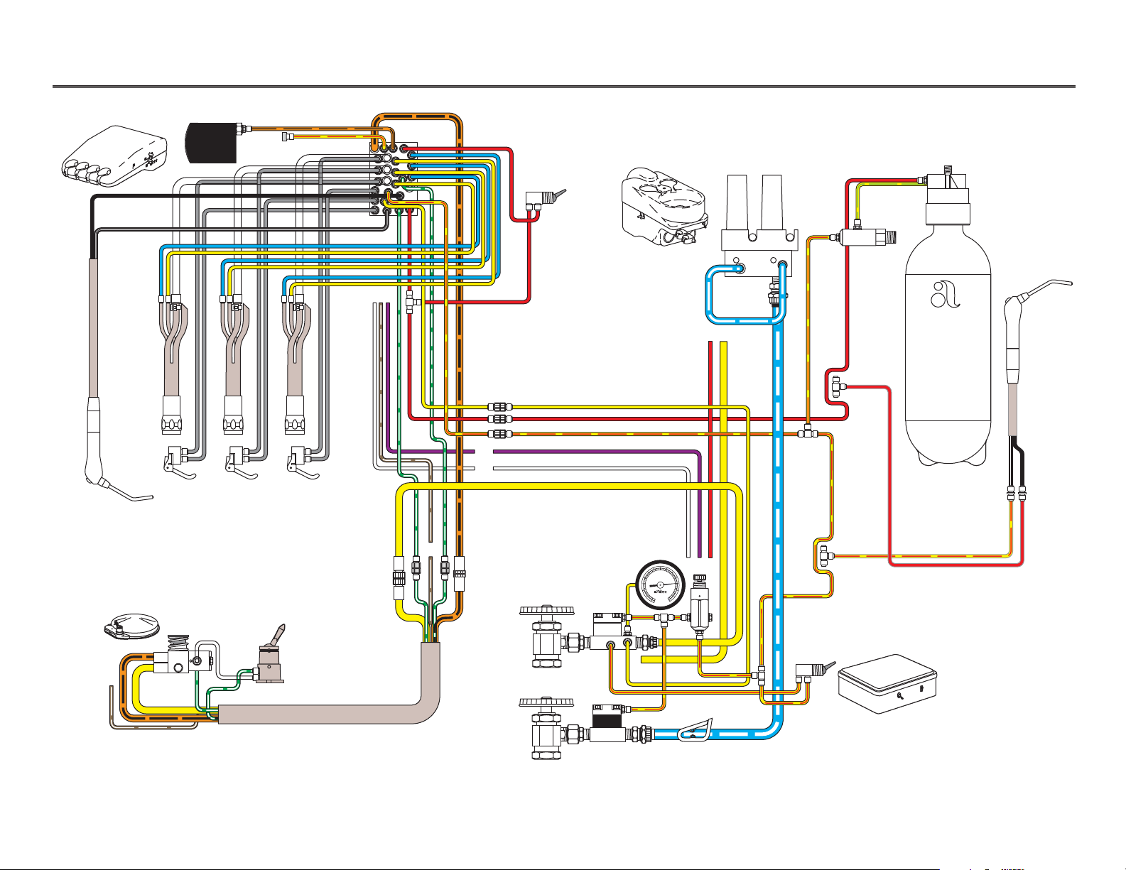
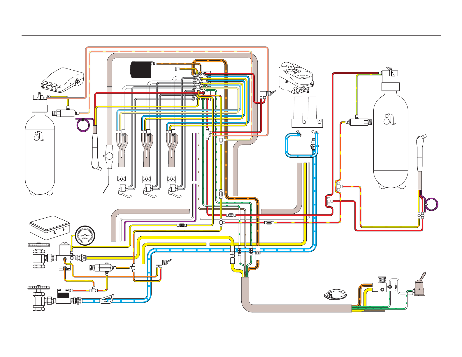
Performer Performer I Flow Diagram
Control head
Foot control
Cuspidor and Assistant’s instrumentation
Optional
assistant’s
syringe
Floor box
34
50
40
60
5
2
30
70
20
80
1
6
90
10
100
0
psi
2
7
0
kg/cm
Page 13
85.0812.00, 2003 PR-12
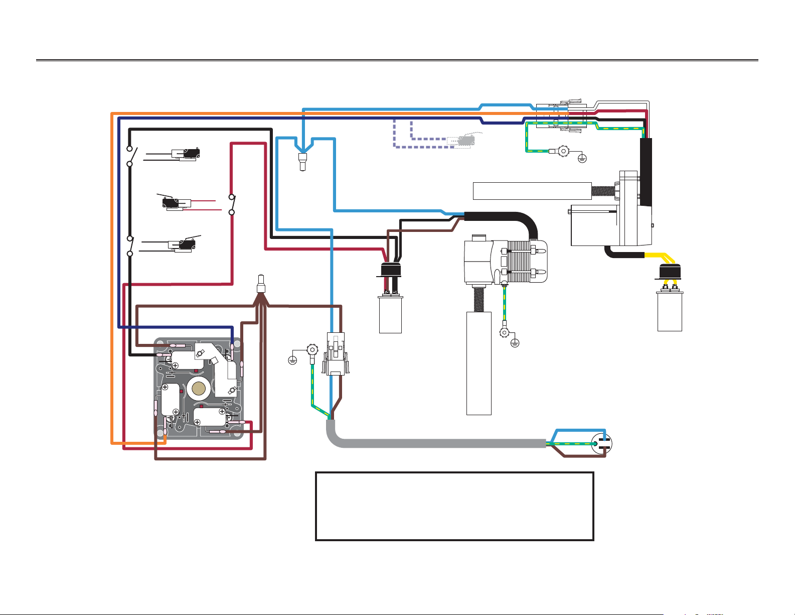
Performer Performer I Electrical Flow Diagram
Tilt actuator
Lift actuator
Tilt capacitor
Lift capacitor
Ground
Ground
BS
DN
BS
UP
BK
DN
BK
UP
Joystick (viewed from the bottom)
Base down
limit switch
Base down
shutoff switch
Base up
limit switch
AC plug
Ground
(NO)
(COM)
(NO)
(COM)
(NO)
(COM)
(NO)
(COM)
WARNING
High voltages are present at motor and limit switch
connections. Unplug the chair before servicing.
Failure to do so could result in serious injury.
Page 14

85.0812.00, 2003
Performer Troubleshooting
Problem
Action
Chair back is inoperative
Chair base is inoperative
Noisy motor
Follow these steps to determine the problem with the chair back.
Task Description
1Make sure system power is ON.
2 Check power and connections.
3 Check for bad capacitors.
Follow these steps to determine the problem with the chair base.
1Make sure system power is ON.
2 Check power and connections.
3 Check for bad capacitors.
Follow these steps to check the motor.
1 Check for loose mounts.
2 Adjust base screw drive nut.
3 Replace motor.
Tips and troubleshooting information are listed to assist in distinguishing Performer I chair problems.
Troubleshooting
Performer I Chair
PR-13
Page 15
85.0812.00, 2003 PR-14
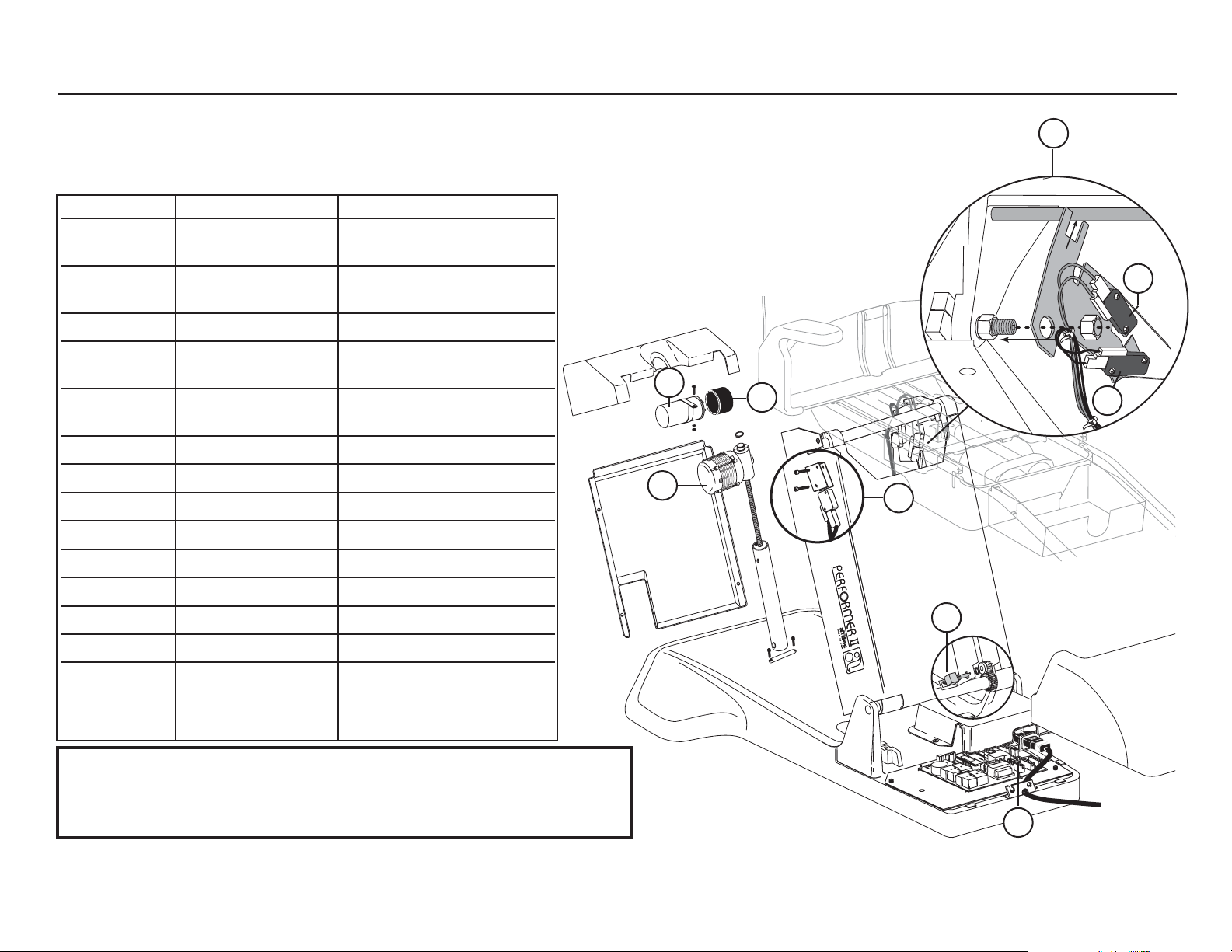
Item # Part Number Description
1— Single articulating headrest
2 61.1569.00 Wear pad, sliding
wedge molded
3 61.2409.00 115V tilt actuator
61.2410.00 230V tilt actuator
4 041.529.00 Capacitor boot
5 90.1035.00 115V tilt actuator capacitor
90.1036.00 230V tilt actuator capacitor
6 041.372.00 Potentiometer, back up
7 61.2181.00 Bearing, flanged
8 004.035.00 Washer, flat, nylatron
9 010.040.01 E-ring, retaining
10 61.2425.00 Pivot pin, back link
Performer II Upper Structure
1
2
9
8
7
4
5
6
3
8
9
10
7
8
7
WARNING
High voltages are present at motor and limit switch
connections. Unplug the chair before servicing.
Failure to do so could result in serious injury.
Holder
Tubing, 3/8" OD
Helical drive shaft
Performer Performer II
ARNING.
W
DO NOT
USE THE
REST
HEAD
IF THE
LINE IS
VISABLE.
Page 16
85.0812.00, 2003
Performer Performer II
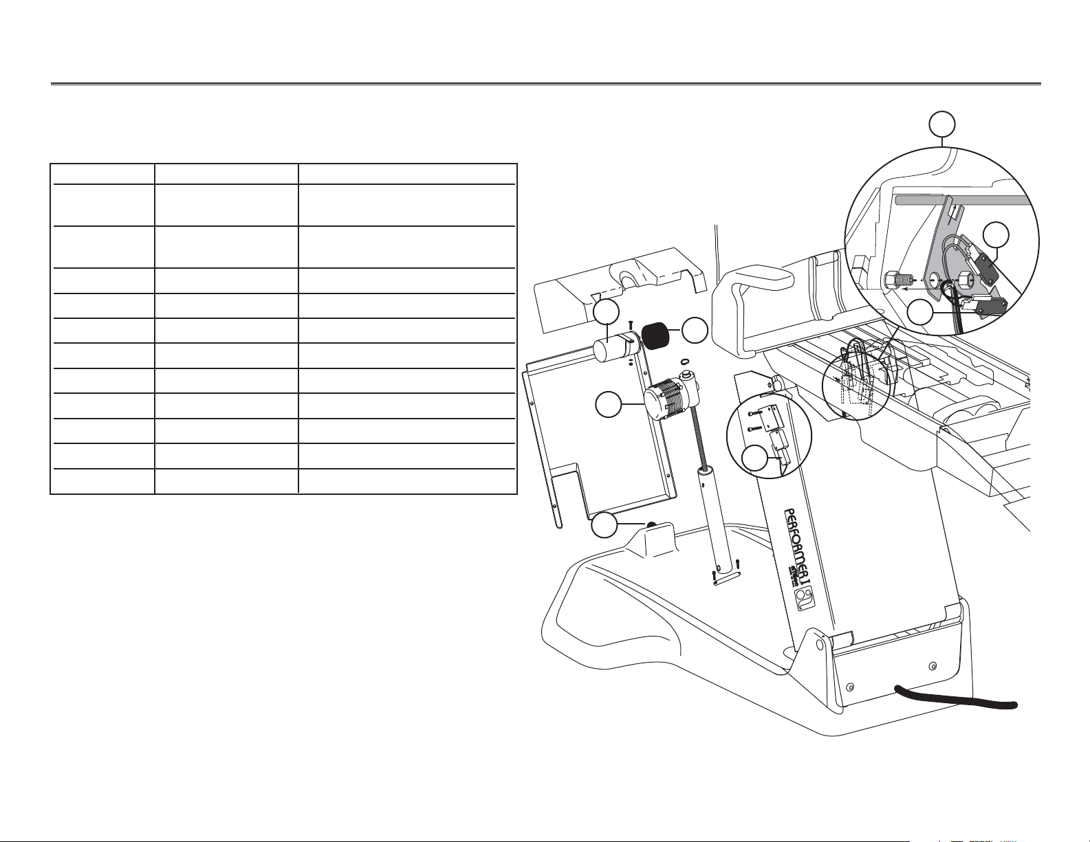
Item # Part Number Description
1 041.583.00 240V base capacitor
(after June 1998)
041.517.00 240V base capacitor
(before June 1998)
041.504.00 440V base capacitor
2 041.529.00 115V capacitor boot
(after June 1998)
041.529.00 115V capacitor boot
(before June 1998)
3 61.2469.00 115V base actuator
61.2470.00 230V base actuator
4— Base down shutoff switch
5 041.372.00 Potentiometer, base up
6 90.1000.00 Base limit switch kit
7 90.1029.00 100V/120V, PCB, chair
90.1029.01 220V/240V, PCB, chair
8 044.184.00 Base up limit switch (Red)
9 044.184.00 Base down limit
switch (Black)
Performer II, Base Structure
1
3
4
5
2
7
9
8
WARNING
High voltages are present at motor and limit switch connections. Unplug
the chair before servicing. Failure to do so could result in serious injury.
NOTE: If the chair limit switch bracket
assembly is not located in the
upper lift arm of the chair, it will
need to be replaced with a limit
switch bracket assembly kit,
P/N 90.1000.00.
6
PR-15
TMTMTMT
M
Page 17
85.0812.00, 2003 PR-16
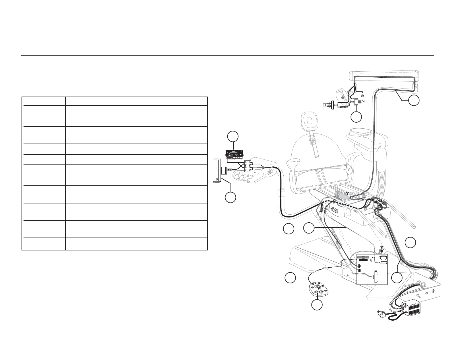
Performer Performer II Flow Diagram
INTR A ORA L
Item # Part Number Description
1 76.1005.00 Intra-oral light source kit
2 76.8000.00 Bitewing x-ray viewer
3 35.1673.00 Cable assembly,
control head
3 28.1264.00 Power cord, 115V
4 28.1276.00 Power cord, 230V
5 61.2108.00 Cable assembly, footswitch
6 61.3043.00 Button footswitch
7 35.1567.00 Cable assembly,
accessory power
8 28.1244.00 Cable assembly,
dental light lower
9 90.1054.00 Cable assembly,
dental light upper
10 90.1039.00 On/Off switch
3
4
8
9
10
75
Performer II Electronics
2
1
NOTE:Performer II chair discontinued in April 1999.
6
ADJUST ONLY
PN 34-0064-00
WHEN BRIGHT
DANGER
INTRA ORAL
LIGHT SOURCE
2.9 - 4.25VDC .8AMP
POWER
24V
BRIGHT
/DC
AC
4321
P9
Page 18
85.0812.00, 2003 PR-17
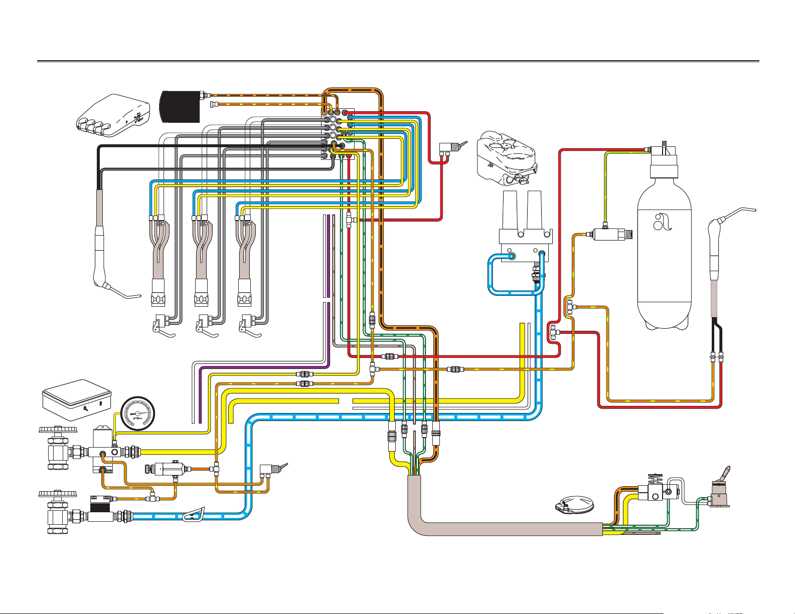
Performer Performer II Flow Diagram
Control head
Foot control
Cuspidor and Assistant’s instrumentation
Optional
assistant’s
syringe
Floor box
NOTE: The Performer II was discontinued
in April 1999.
34
50
40
60
5
2
30
70
20
80
1
6
90
10
100
0
psi
2
7
0
kg/cm
Page 19
85.0812.00, 2003 PR-18
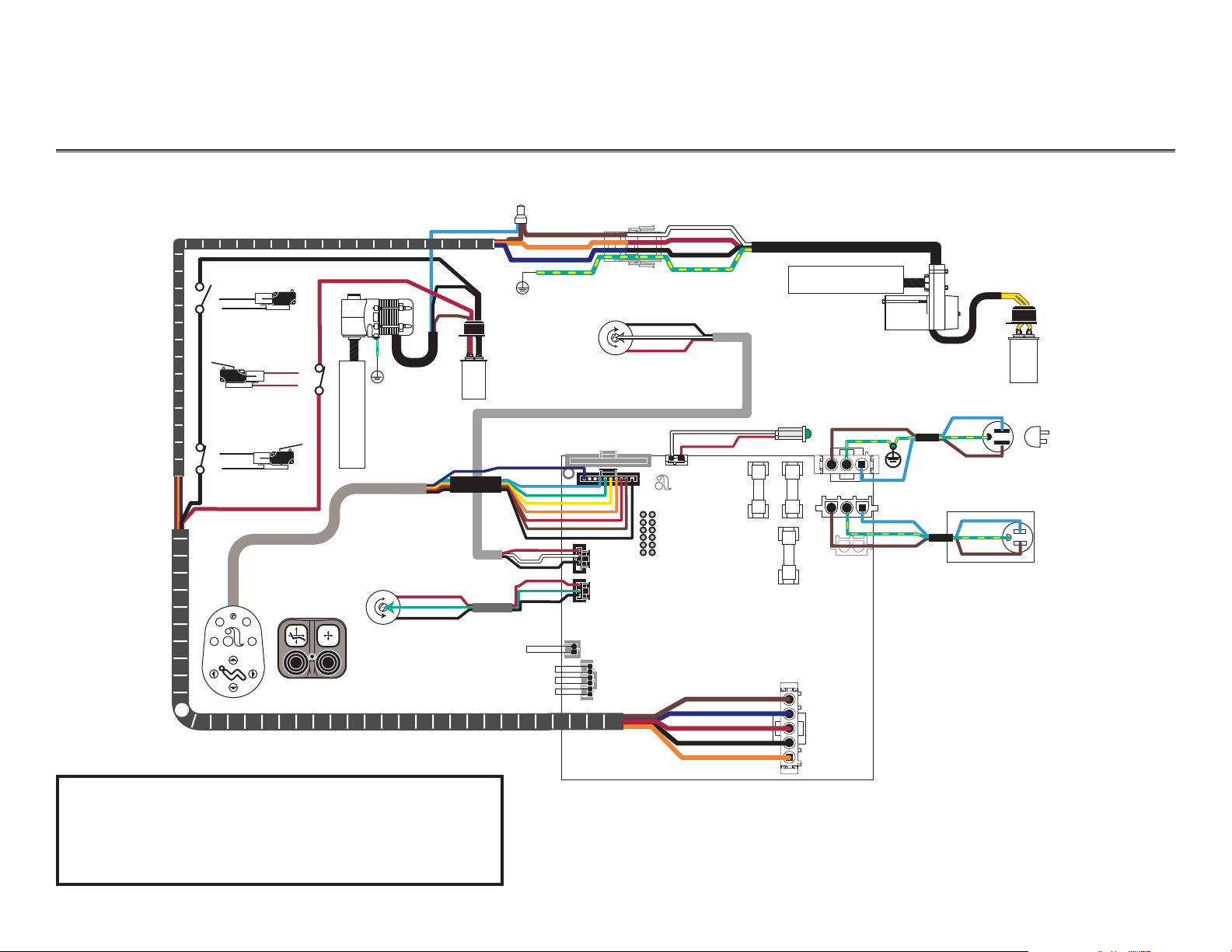
Performer Performer II Electrical Flow Diagram
Tilt actuator
Lift actuator
Tilt
capacitor
Lift
capacitor
Base down
limit switch
Base down
shutoff switch
Base up
limit switch
AC plug
Ground
Tilt (back) potentiometer
back up = clockwise
Lift (base) potentiometer
base up = counterclockwise
(NO)
(COM)
(COM)
WARNING
High voltages are present at motor and limit switch
connections. Unplug the chair before servicing.
Failure to do so could result in serious injury.
(NO)
(NO)
(COM)
2
1
3
0
210
3
P1
TEST POINTS
P5
P4
P14 CUSP
JUMPER
JUMPERS
P6
P2
IND. LAMP
ENT
EXT
DN
BS UP
BK DN
BK UP
P16
P11
F2
F1
P12
P9
F3
P10
Page 20

85.0812.00, 2003 PR-19
Performer Troubleshooting
Problem
Action
Chair back or base is inoperative
Noisy motor
Automatic positions erratic
Follow these steps.
Task Description
1Make sure system power is ON.
2 Check power and connections.
3Check for bad fuses on the circuit board.
4 Operate chair from printed circuit board test points.
5 Check for bad capacitors.
Follow these steps.
1 Check for loose mounts.
2 Adjust base screw drive nut.
3 Replace motor.
• Check potentiometers and wiring
• Replace the circuit board
Troubleshooting
Performer II Chair
Tips and troubleshooting information are listed to assist in distinguishing Performer II
chair problems.
Page 21
85.0812.00, 2003 PR-20
Performer Performer III
Item # Part Number Description
1 006.122.01 Retainer nut
2 61.2740.00 Pin
3 007.069.00 Setscrew
4 61.2741.01 Back link
5 007.042.00 Setscrew
6 61.2082.00 Slide
7 61.2693.00 Tilt rod
8 61.2050.01 Tilt cylinder
9 013.054.00 Spring
10 041.372.00 Potentiometer
Performer III Upper Structure
1
3
2
3
5
4
6
6
7
8
10
9
Page 22
85.0812.00, 2003 PR-21
Performer Performer III
Performer III Lower Structure
1
2
5
4
3
6
8
12
10
9
11
7
Item # Part Number Description
1 61.1287.00 Lift cylinder
2 044.184.01 Base up limit switch
3 004.148.00 Flat washer
4 001.165.00 Socket shoulder screw
5 001.164.00 Socket shoulder screw
6 61.3043.00 Button foot switch
7 61.2142.00 Pump cover
8 90.1029.00 PCB, 120V
90.1029.01 PCB, 240V
9 90.1032.00 Capacitor (after 6/1/98)
90.1033.00 Capacitor
(before 6/1/98)
90.1034.00 Base capacitor
10 61.0460.00 Flow adjustment screw
11 001.002.01 Truss head screw
002.118.02 Button head screw
12 61.1335.00 Solenoid, 100V,
Yellow wires
61.1336.00 Solenoid, 120V,
Black wires
61.1337.00 Solenoid, 240V,
Red wires
Page 23
85.0812.00, 2003 PR-22
Performer Performer III Flow Diagram
BRIGHT
POWER
ADJUST ONLY
2.9 - 4.25 VDC .8AMP
PN 34-0064-00
WHEN BRIGHT
DANGER
24V
AC
DC
INTRA ORAL
LIGHT SOURCE
ON
CB2
CB1
"STATIC SENSITIVE
"
P
17
P5
P2
P1
S1
P4
S2
P6
B
S
P
O
T
BK
P
O
T
BKUP
PRGM
B
EE
P
E
R
PUMP
(
100
-
120
V
~
)
N/L2
DS3
DS5
DS12
DS8
P14
CUSP
STATUS
P16
P12
P11
DS15
BK UP
DS14
DS7
DS13
DS4
BS UP
BK UP
BS UP
BS DN
BK DN
N/L2
BS DN
BK DN
PUMP
K5
PUMP
P9
LOCKOUT
P13
DS1
DS16
DS17
DS2
DS11
DS6
DS9
DS10
+12V
+5V
BSU
P
BSDN
BK
DN
PRGM
0
PRGM
1
PRGM
2
PRGM
3
EN/DIS TP/F
S
FACT DEFAU
LT
BK POT
BS PO
T
SPAR
E
SPAR
E
TEST POINTS
P10
N/L2
N/L2
AUXILIARY
OUTPUT POWE
R
(2A MAX
)
MAINS
INPUT POWER
R74
R72
R73
SET
S
O
FF
O
N
O
FF
O
N
O
FF
O
FF
O
N
O
N
CUSP/RET
LAST POST
PRGM
3
NOT USE
D
B
S
BK
SP
(
220
-
240
V
~
)
P
A
R
T
#
1
3
12
15
16
10
2
5
11
6
4
7
8
9
14
13
Performer III Electronics
Item # Part Number Description
1 35.1673.00 Cable assembly, control head
2 76.1005.00 Single volt intra-oral light source
3 76.8100.00 Bitewing viewer
4 39.1385.00 Touchpad
5 76.0144.00 Cable assembly, touchpad
6 61.2099.00 Limit switch, back up
7 61.1503.00 Back electric wiring cable
8 61.1502.00 Base electric wiring cable
9 61.2108.00 Cable assembly, foot switch
10 61.3043.00 Button footswitch
11 35.1567.00 Cable assembly,
accessory power
12 28.1244.00 Cable assembly,
dental light, lower
13 28.1264.00 Power cord, 115V
13 28.1276.00 Power cord, 230V
14 41.1444.00 Ground wire assembly
15 90.1054.00 Cable assembly,
dental light, upper
16 90.1039.00 On/Off switch, dental light
ADJUST ONLY
PN 34-0064-00
WHEN BRIGHT
DANGER
INTRA ORAL
LIGHT SOURCE
2.9 - 4.25VDC .8AMP
POWER
24V
BRIGHT
AC
/DC
P1
P2
S1
PRGM
P5
T
O
P
BK
P4
T
O
P
S
B
DS1
DS2
ON
S2
1 2
P6
SP
BK
S
B
R
E
P
EE
B
DS8
DS15
AUXILIARY
CB2
CB1
MAINS
OUTPUT POWE
R
INPUT POWER
P14
P16
(2A MAX
)
CUSP
STATUS
L1L1N/L2
L1L1N/L2
P11
P12
P
17
TEST POINTS
BKUP
BSU
P
BSDN
BK
DN
DS3
PRGM
0
PRGM
1
PRGM
2
PRGM
3
EN/DIS TP/F
FACT DEFAU
DS5
BK POT
BS PO
T
SPAR
E
SPAR
E
"STATIC SENSITIVE
#1#1#2#2SET
S
O
FF
O
FF
CUSP/RET
O
N
O
FF
LAST POST
O
FF
O
N
PRGM
3
O
N
O
N
NOT USE
D
DS6
DS9
DS10
DS17
+12V
P10
BK UP
DS12
S
LT
"
N/L2
BK UP
BS UP
DS14
BS UP
BS DN
BS DN
DS7
BK DN
BK DN
DS13
P9
PUMP
K5
PUMP
DS11
PUMP
P13
N/L2
LOCKOUT
DS4
)
~
V
R73
240
220
(
DS16
+5V
#
)
~
T
V
R72
R
A
120
-
P
R74
100
(
Page 24
85.0812.00, 2003 PR-23
Performer Performer III Flow Diagram
Control head
Foot control
Optional
assistant’s
syringe
Cuspidor and Assistant’s instrumentation
Floor box
Optional
control head
mounted selfcontained
water (for
systems without cuspidor)
Optional control
head saliva ejector
34
50
40
60
5
2
30
70
20
80
1
6
90
10
100
0
psi
2
7
0
kg/cm
Page 25
85.0812.00, 2003 PR-24
Performer Performer III Electrical Flow Diagram
PUMP
N/L2
P14
CUSP
STATUS
P16
DS4
DS6
DS9
DS10
ON
CB2
CB1
"STATIC SENSITIVE"
Performer III (LEDs)
3
2
4
5
6
8
7
1
To post box
Led light
Optical duplex
100V and 120V only
From electrical
outlet
Ground
To hydraulic
motor pump
Item # Part Number Description
1 61.3043.00 8-function footswitch
2 041.372.00 Positioning potentiometer, back
3 041.372.00 Positioning potentiometer, base
3 28.1264.00 Power cord, 115V
4— Safety stop limit switch
5 61.2065.00 Back up limit switch (1040 only)
6 044.184.01 Base up limit switch (1040 only)
7 90.1031.00 Capacitor with boot (100-120V)
90.1034.00 Capacitor with boot (240V)
8 61.1332.00 Manifold assembly, hyd, 100V
61.1333.00 Manifold assembly, hyd, 120V
61.1334.00 Manifold assembly, hyd, 240V
0
1
2
3
DS8
#1 #2 SETS
OFF
ON
OFF
ON
DS6
DS9
DS10
TEST POINTS
OFF
OFF
ON
ON
P17
CUSP/RET
LAST POST
PRGM 3
NOT USED
P14
CUSP
BKUP
BSUP
BSDN
BKDN
PRGM 0
PRGM 1
PRGM 2
PRGM 3
EN/DIS TP/FS
FACT DEFAULT
BK POT
BS POT
SPARE
SPARE
"STATIC SENSITIVE"
+12V +5V
DS15
P16
STATUS
AUXILIARY
OUTPUT POWER
(2A MAX)
L1
N/L2
BK UP
DS12
BS UP
DS14
BS DN
DS7
BK DN
DS13
K5
PUMP
DS11
P13
LOCKOUT
DS4
DS16DS17
CB2
CB1
MAINS
INPUT POWER
L1 N/L2
P11
P12
P10
N/L2
BK UP
BS UP
BS DN
BK DN
P9
PUMP
PUMP
N/L2
(220-240V~)
PART #
R74 R72 R73
(100-120V~)
P1
P2
S1
PRGM
P5
DS3DS5
BK POT
P4
BS POT
DS1
DS2
ON
S2
1 2
P6
BS BK SP
BEEPER
Page 26
85.0812.00, 2003 PR-25
Performer Adjustments
Adjusting the
Hydraulic Manifold
Base down
control valve
Base up
control valve
Back down
control valve
Back up
control
valve
CAUTION
Do not remove retaining screw from the manifold.
Do not completely close a speed control valve. The
motor/pump could overheat and become damaged
from pumping against a closed valve.
Retaining
screws
To adjust... Do this...
Base up speed Turn base up control valve:
clockwise to decrease speed, or
counterclockwise to increase speed.
Base down speed Turn base down control valve:
clockwise to decrease speed,
or counterclockwise to increase speed
Back up speed Turn back up control valve counterclockwise to decrease
speed, or clockwise to increase speed. Back down speed.
Turn the back down control valve, clockwise to decrease
speed, or counterclockwise to increase speed.
The hydraulic manifold incorporates four speed control valves which restrict or divert the flow of
hydraulic fluid to and from the lift and tilt cylinders.
NOTE: The speed control valves are hex drive.
NOTE: This is opposite of the other three control valves.
Turning the back up valve counterclockwise too
far may disable this function.
Page 27
85.0812.00, 2003 PR-26
Performer Hydraulic Manifold
Removing a
Solenoid
Installing
a Solenoid
To remove a solenoid:
1 Lower the chair base and back to the full down position to depressurize the
hydraulic system. Remove the motor pump cover, then unplug the chair.
2 If necessary, remove the two mounting screws that secure the manifold
to the hydraulic tray. Rotate that manifold so the solenoids
are accessible.
3Using a flat blade screwdriver and a 9/16" wrench, remove
the defective solenoid.
4 Cut the defective solenoid wires 3" (74mm) from the coil
and discard.
5Remove the old o-ring from the solenoid cavity and clean
out any excess oil. Replace the o-ring with the correct o-ring
provided in the kit.
Hydraulic manifold
O-ring
Poppet sleeve
Washer
ID washer
Retaining
nut
Poppet
Coil
Wire nut
J10
WARNING
The solenoid coils are powered by line voltage (100, 120, or 240V AC).
Failure to unplug the chair may result in serious injury from electrical shock.
The following steps will guide you through the procedure for installing a solenoid.
Page 28

85.0812.00, 2003 PR-27
Performer Hydraulic Manifold
Replacing a
Solenoid
To replace a solenoid:
1 Install the new solenoid stem and poppet into the manifold and tighten to 35-40 in lb
(.11985–.2284 Nm). Position the remaining solenoid parts on the stem and secure by
tightening the retaining nut to 25-30 in lb (.14275–.1713 Nm).
2 Cut the solenoid wires 3" (75 mm) from the coil. Install the stripped wires from the
solenoid and the connector housing into a wire nut. Repeat for the remaining wire.
3Using the mounting screws, secure the manifold to the hydraulic tray.
4. Plug in the chair. Test the chair functions to ensure proper operation and that no
fluid leakage occurs. Reinstall the motor pump cover.
Page 29
85.0812.00, 2003 PR-28
Performer Troubleshooting
Task Description
1 Remove the motor/pump cover from the chair.
2 Fit a 5/8" wrench to the high pressure outlet port
(either lift or tilt, whichever is in hydrostatic lock) of
the hydraulic manifold. Hold the port still and use a
9/16" wrench to loosen the hose fitting.
3 Place a shop rag around the fitting to absorb
the fluid.
4 Carefully loosen the fitting counterclockwise until
oil begins to leak from the fitting. Retighten the
fitting. Operate the down function. A second release
of hydraulic fluid may be required.
5 Adjust the limit switch that caused the hydrostatic
lock (refer to Adjusting the Base Up Limit Switch). In
some cases it may be necessary to remove and
replace the limit switch. Adjust the new limit switch
as needed. Also ensure that the large gear/actuator
is securely installed and not slipping.
6Cycle the chair a couple of times to verify it is no
longer in hydrostatic lock.
Tilt cylinder
high pressure
fitting
Lift cylinder
high pressure
fitting
Correcting
Hydrostatic
Lock
Hydraulic lock occurs based on the following conditions:
•chair base or back is stuck in full up position
• limit switch not activated, or
• down solenoid poppet is unable to open based on excess hydraulic pressure.
Correcting Hydrostatic Lock
Page 30
85.0812.00, 2003 PR-29
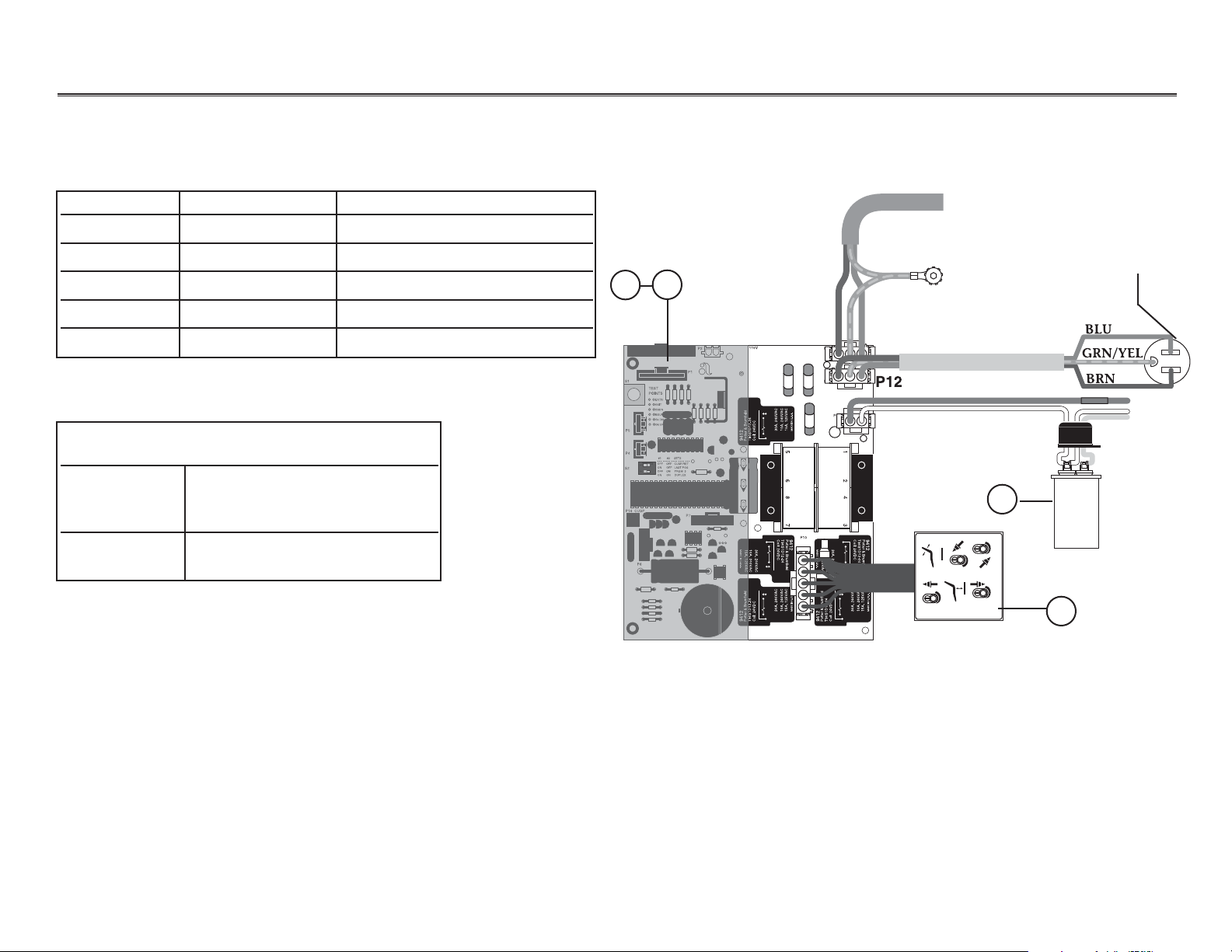
Performer Performer III Electrical Diagram
Performer III (No LEDs)
1
2
3
4
Item # Part Number Description
1 61.2512.00 Printed circuit board, 240V
2 61.2510.00 Printed circuit board, 100-120V
3 61.1333.00 Hydraulic manifold, 120V
3 61.1334.00 Hydraulic manifold, 240V
4 90.1031.00 Capacitor
From electrical outlet
Optional accessory
power cord
Ground
NOTE: P12 should be used for
the optional accessory
power cord.
NOTE:Solenoid wire color
varies with voltage.
To Replace Circuit Board
Part Number Order this kit
61.2510.00 90.1029.00 (100-120V)
61.1214.01
61.1373.01
61.2512.00 90.1029.01(220-240V)
61.1217.01
S1
P5
P4
S2
P14 CUSP
TEST
POINTS
ENTR
EXIT
BSDN
BSUP
Bk DN
Bk UP
#1 #2 SETS
- - - - - - - - - - - - - - - - - - -
ON
12
OFF OFF sCUSP/RET
ON OFF LAST POS
OFF ON PRGM 3
ON ON DUPLEX
P6
100 - 120 V
P2
P1
9412
P7
MADE IN U.S.A.
9412
A-DEC 61-1215-00 REV L ASSY 61-1214-01 REV E
Page 31

85.0812.00, 2003 PR-30
Performer Performer III Electrical Diagram
9412
Potter & Brumfield
T90S1D12-24
Coil: 24VDC
30A, 240VAC
MADE IN U.S.A.
30A, 240VAC
MADE IN U.S.A.
10A, 240VAC
15A, 125VAC
9412
Potter & Brumfield
T90S1D12-24
Coil: 24VDC
9412
Potter & Brumfield
T90S1D12-24
Coil: 24VDC
30A, 240VAC
MADE IN U.S.A.
10A, 240VAC
15A, 125VAC
9412
Potter & Brumfield
T90S1D12-24
Coil: 24VDC
30A, 240VAC
MADE IN U.S.A.
10A, 240VAC
15A, 125VAC
1243
5687
P9
P12
P11
P1
P5
P4
P14 CUSP
P7
P10
P6
S1
S2
12
ON
- - - - - - - - - - - - - - - - - - -
#1 #2 SETS
OFF OFF sCUSP/RET
ON OFF LAST POS
OFF ON PRGM 3
ENTR
TEST
POINTS
EXIT
BSDN
BSUP
Bk DN
Bk UP
9412
Potter & Brumfield
T90S1D12-24
Coil: 24VDC
30A, 240VAC
MADE IN U.S.A.
10A, 240VAC
15A, 125VAC
9412
Potter & Brumfield
T90S1D12-24
Coil: 24VDC
30A, 240VAC
MADE IN U.S.A.
10A, 240VAC
15A, 125VAC
9412
30A, 240VAC
MADE IN U.S.A.
10A, 240VAC
15A, 125VAC
9412
Potter & Brumfield
T90S1D12-24
Coil: 24VDC
30A, 240VAC
MADE IN U.S.A.
10A, 240VAC
15A, 125VAC
1243
5687
T90S1D12-24
Coil: 24VDC
Potter & Brumfield
T90S1D12-24
Coil: 24VDC
1
2
3
0
1
2
3
4
6
7
9
10
12
11
5
8
To chair touchpad
Printed circuit
board assembly
Performer III
(No LEDs)
Item # Part Number Description
1 39.1385.00 Chair touchpad kit
2 041.582.00 LED light
3 61.2108.00 Cable assembly,
button footswitch
4 61.1503.00 Cable assembly,
potentiometer, back up
5 61.1502.00 Cable Assembly,
potentiometer, base up
6 041.372.00 Potentiometer, back
7 041.372.00 Potentiometer, base
8 61.3043.00 Button footswitch
8 61.3048.00 Button footswitch,
membrane
8 61.3049.00 Button footswitch, boot
9 Limit switch, safety
10 044.184.00 Limit switch, back up
11 044.184.01 Limit switch, base up
12 61.2099.00 Cable assembly,
limit switch
Page 32

85.0812.00, 2003 PR-31
Performer Performer III Electrical Diagram
Performer III (No LEDs)
1
Item # Part Number Description
1 90.1029.00 Circuit board assembly, 100V-120V
90.1029.01 Circuit board assembly, 240V
2 044.192.00 Fuse, 10 A, 5x20 mm time lag,
240V (61.2510.00 CBA, 120V)
044.147.00 Fuse, 6.3 A (61.2512.00 CBA, 240V)
3 044.193.00 Fuse, .063 A, 5x20MM, time lag,
250V (61.2510.00 CBA, 120V)
044.194.00 Fuse, .040A (61.2512.00 CBA, 240V)
2
3
NOTE:Refer to the
Genuine A-dec Service Parts Catalog
for information
on fuses that worked on previous styles of printed circuit boards.
There are no replacement fuses on the following circuit boards:
61.2774.00 (100-120V) and 61.2774.01 (220-240V).
Page 33

85.0812.00, 2003 PR-32
Performer Performer III Diagnostic LEDs for the Circuit Board
LEDs
NOTE: Refer to
Testing Factory Defaults
for more details.
DS1
DS2
DS3
DS7
DS8
DS9
DS10
DS11
DS12
DS13
DS4
DS5
DS6
DS14
DS15
DS16
DS17
R73
R72
R74
Page 34

85.0812.00, 2003 PR-33
Performer Performer III Diagnostic LEDs for the Circuit Board
LED Description Information Communicated
DS1 S2 (red DIP switch) is ON Switch is ON
DS2
DS3 Back Potentiometer LED ON Back potentiometer is functioning normally when the chair back is moving
DS4 Handpiece Lockout LED ON Lockout enabled
DS5 Base Potentiometer LED ON Base potentiometer is functioning normally when the chair base is moving
DS6 Chair Stop Plate Limit Switch LED ON Chair stop plate limit switch activated
DS7 Base Down LED Relay is ON when LED is ON and the function is moving
DS11 Pump LED
DS12 Back Up LED
DS13 Back Down LED
DS14 Base Up LED
DS8 Cuspidor Limit Switch LED ON Cuspidor limit switch activated, or jumper is missing
DS9 Back Up Limit Switch LED ON Back Up limit switch activated
DS10 Base Up Limit Switch LED ON Base Up limit switch activated
DS15 Status LED ON ON: Normal operation
Off: Microcontroller is not functioning. Verify voltage regulator LEDs
(DS16 and DS17) are ON. Is the chair plugged in? Circuit breaker tripped?
Slow Blink: Check cuspidor (DS8) and stop plate (DS6) limit switch LEDs
Fast Blink: Check handpiece lockout (DS4) LED
Double Blink: A SPARE jumper is in the FACT DEFAULT position
DS16 5V Regulator LED OFF 1 Power to circuit board is OFF, or
2 There is a short in the cable to the base or back potentiometer. Disconnect all cables
except the power cable. Plug the cables in one at a time (the LED will turn ON when the
problem is fixed).
DS17 12V Regulator LED OFF 1 1 Power to circuit board is OFF, or
2. There is a short in the cable to the status light or limit switch (the LED will turn ON when
the problem is fixed).
Page 35

85.0812.00, 2003 PR-34
Performer Performer III Printed Circuit Board (PCB)
Testing and
Programming
the Circuit Board
Follow these steps to test and program the chair circuit board.
Task Description
1 Insert the SPARE jumper into the FACT DEFAULT location (on P17).
Result: The chair will cycle the base and back movements and automatically
reprogram the memory positions to the factory settings
(position 0 to entry/exit; 1 and 2 to the same pre-programmed positions;
and 3 to cuspidor/return).
If the circuit board beeps three times, continue with step two.
If the circuit board beeps just once, the chair cycle has been interrupted. Diagnose
and correct any errors, then press either circuit breaker for five seconds to restart
the cycle (refer to Testing Factory Defaults).
2Move the jumper from the FACT DEFAULT location (on P17) back to the
SPARE location.
NOTE: The jumper must be in the SPARE position for normal chair functions and
safe operation.
3Press “1” on the touchpad or footswitch or green position on the 8-function
footswitch.
Result: The chair will move to the operating position.
4Press “0” on the touchpad or footswitch, or the red button on the 8-function
footswitch.
Result: The chair will move to the entry/exit position.
NOTE: The chair programmable position buttons can be reprogrammed to the
desired positions as specified by the dental team.
WARNING
The chair will begin to move
automatically during this
test; to avoid injury or
equipment damage, remove
all possible obstructions and
maintain a safe distance
from the chair. To interrupt
the chair cycle, press any
button on the touchpad or
footswitch, or activate the
chair stop plate.
Page 36

85.0812.00, 2003 PR-35
Performer Tests
Problem Action
Factory Default test will not start
(LEDs DS15, DS16 and DS17
are Off)
Factory Default test will not start
(LED DS15 is Off; DS16 and DS17
are ON)
Factory Default test will not start
(LED DS15 is blinking; DS16 and
DS17 are ON)
If . . .
Then . . .
Transformer thermal limiter is open
Circuit breaker is tripped
Wait for transformer to cool off.
Reset circuit breaker (short circuit fault currents
may damage the circuit breaker and prevent it
from resetting).
If . . .
Then . . .
Input voltage is too low or is outside the
required range
Microcontroller is not functioning
Ve rify input voltage and voltage selection
resistors (100-120VAC=R72 and R74)
(220-240VAC=R73).
Replace the circuit board.
If . . .
Then . . .
Input voltage is too low or is outside the
required range
Microcontroller is not functioning
Ve rify input voltage and voltage selection
resistors (100-120VAC=R72 and R74)
(220-240VAC=R73).
Replace the circuit board.
Testing Factory Defaults
The table lists conditions and corrective actions for testing the factory defaults for LEDs.
Page 37

85.0812.00, 2003 PR-36
Performer Tests
Problem Action
Factory Default test halts during
the BASE UP test and the PCB
board beeps one time
Factory Default test halts during
the BACK DOWN test and PCB
board beeps one time
If . . .
Then . . .
Input voltage is too low or is outside the
required range
Base Up limit switch is activated
Motor thermal limiter is open, motor is hot
Motor capacitor is defective
Base Up solenoid is defective
Base is in hydrostatic lock
Potentiometer is not changing voltage
Ve rify input voltage and voltage selection
resistors (100-120VAC=R72 and
R74 (220-240VAC=R73).
Verify switch operation.
Wait for motor to cool off.
Test capacitor and replace, if needed.
Test solenoid and replace, if needed
Refer to Correcting Hydrostatic Lock.
Ve rify potentiometer LED comes ON when base
is moving.
Check potentiometer mechanical drive and
electrical connections.
If . . .
Then . . .
Stop plate limit switch is activated
Stop plate is jammed
Back Down solenoid is defective
Back is in hydrostatic lock
Potentiometer is not changing voltage
Verify switch operation.
Remove and reinstall the stop plate.
Test solenoid and replace, if needed
Refer to Correcting Hydrostatic Lock.
Ve rify potentiometer LED is ON when back
is moving.
Check potentiometer mechanical drive and
electrical connections.
Page 38

85.0812.00, 2003
Performer Tests
PR-37
Problem Action
Factory Default test halts during
the BACK UP test
Factory Default test halts during
the BASE DOWN test
Chair moves by itself when power
is turned ON
If . . .
Then . . .
Back up limit switch is activated
Back Up solenoid is defective
Back is in hydrostatic lock
Potentiometer is not changing voltage
Verify switch operation.
Test solenoid and replace, if needed.
Refer to the Correcting Hydraulic Lock.
Ve rify potentiometer LED is ON when back
is moving.
Check potentiometer mechanical drive and
electrical connections.
If . . .
Then . . .
Stop plate limit switch is activated
Base Down solenoid is defective
Base is in hydrostatic lock
Potentiometer is not changing voltage
Verify switch operation.
Test solenoid and replace, if needed.
Refer to Correcting Hydraulic Lock.
Ve rify potentiometer LED is ON when base
is moving.
Check potentiometer mechanical drive and
electrical connections.
If . . .
Then . . .
The jumper is in FACT DEFAULT position
Short circuit in touchpad or footswitch
Short circuit on circuit board
Verify that the jumper is in the
SPARE position.
Unplug the touchpad and footswitch; reset the
circuit breaker. If the problem isn’t repeated, the
touchpad or footswitch may have shorted.
Replace the circuit board.
Page 39

85.0812.00, 2003 PR-38
Performer Performer III Printed Circuit Board (PCB)
Raise the chair with the
stop plate limit switch
Enable and disable touchpad
and footswitch buttons
Handpiece lockout
Plug the chair into an electrical outlet.
Tap the chair stop plate three times within five seconds and hold on the third tap.
Result: The chair base will continue to rise as long as the stop plate is held in. This function is
automatically disabled after five minutes but is re-enabled upon each power up. To reset the
five-minute timer, depress either circuit breaker until the LEDs turn OFF, then release the
circuit breaker.
Place the SPARE jumper in the EN/DIS TP/FS position of the Test Points header P17.
Push the buttons to be Enabled or Disabled (PRGM, PRGM 0, PRGM 1, PRGM 2, PRGM 3).
Result: One beep indicates the button is disabled. Three beeps indicate the button in enabled.
Place the SPARE jumper back into the SPARE position of the Test Points header P17.
Plumb a normally open air-electric switch (kit P/N 61.1384.00) to the air-coolant tubing (green with
long white dashes).
Insert the two position connector from the air-electric switch into P13 Lockout (next to the transformer).
Feature Programming
The chart provides information on new features and associated programming on the PCB.
Identifying
New Features
Page 40

85.0812.00, 2003 PR-39
Performer Performer III Printed Circuit Board (PCB)
Diagnostic LEDs
Test Points Header
See Performer III Diagnostic LEDs for the Circuit Board.
Use a SPARE jumper to test the chair manual functions (BKUP, BSUP, BSDN, BKDN).
BK POT and BS POT points allow test meter check of potentiometer voltages and measurement of the
analog DC voltage from pin 2 of the potentiometer.
Feature Programming
Page 41

85.0812.00, 2003 PR-40
Performer Headrests
Single-Articulating Headrest
(Discontinued)
Item # Part Number Description
1 61.2355.XX Formed headrest upholstery assy
2 Not a serviceable part
3 61.2350.00 Headrest cover
NOTE:For upholstery color availability, refer to the current
A-dec Standard Upholstery Guide
.
1
2
3
Page 42

85.0812.00, 2003 PR-41
Performer Headrests
Double-Articulating Headrest
NOTE:For upholstery color availability, refer to the current
A-dec Standard Upholstery Guide
.
1
2
Item # Part Number Description
1 61.2116.XX Formed headrest upholstery assy
2 027.035.01 Height adjustment knob, Gray
027.035.00 Height adjustment knob, Black
Page 43

85.0812.00, 2003 PR-42
Performer Headrests
Headrest Instrument Holder
(For single-articulating headrest)
1
2
3
Item # Part Number Description
1 99.0584.00 Cascade individual assistant’s holder
(includes friction pad and setscrew)
2 45.0403.00 Friction pad, Black
3 007.042.00 Set screw, socket cup point
Page 44

Performer Headrests
Headrest Instrument Holder Kit
(For double-articulating headrest)
1
2
3
Item # Part Number Description
1 99.0584.00 Cascade individual assistant’s holder
(includes friction pad and setscrew)
2 45.0403.00 Friction pad, Black
3 007.042.00 Set screw, socket cup point
PR-4385.0812.00, 2003
Page 45

85.0812.00, 2003 PR-44
Performer Adjustments
Using the Headrest
Adjusting
Headrest Position
Adjusting Headrest Glide
Bar Tension
The double articulating headrest offers complete
versatility in head positioning. This headrest
allows the doctor/assistant to position the headrest
to fit the nape of the patient’s neck, and to tilt to
the head to almost any position.
Loosen the knob on the back of the headrest. Move
the headrest into the desired position. Tighten the
headrest knob.
The headrest should move freely while positioning
yet maintain its position when set. Turn the tension
adjustment screw clockwise to increase friction and
hold the headrest more securely. Turn the tension
adjustment screw counterclockwise to decrease
friction and allow the headrest to move up and
down more freely.
1/8" hex key
Page 46

85.0812.00, 2003 PR-45
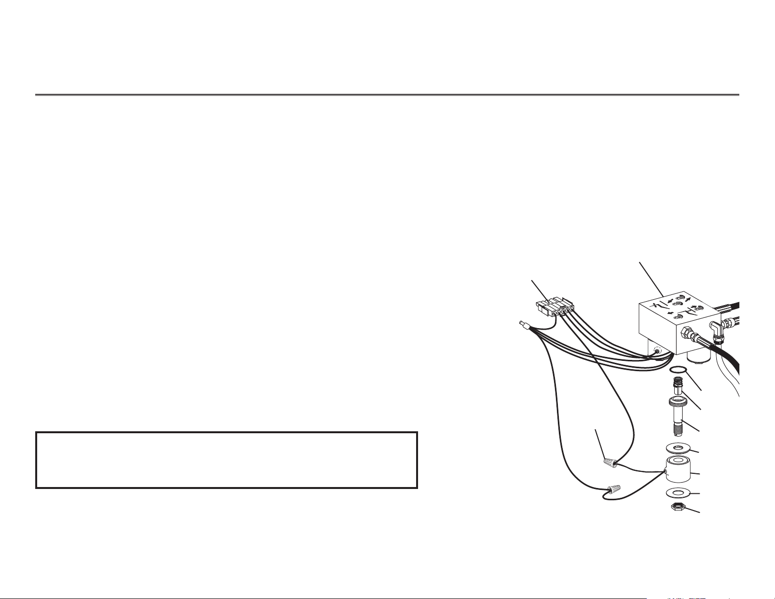
Performer Hydraulic Manifold
Hydraulic Manifold
Item # Part Number Description
1 61.1335.00 Solenoid, 8-watt, 100V, Yellow wires
61.1336.00 Solenoid, 8-watt, 120 V, Black wires
61.1337.00 Solenoid, 8-watt, 240 V, Red wires
2 030.015.02 O-ring pkg 10
3 030.004.02 O-ring, AS568-004 pkg 10
4 61.0460.00 Flow adjust screw with o-ring
5 002.118.01 Screw, button-head, socket
6. 61.1333.00 Manifold assy, hyd, 120V
61.1334.00 Manifold assy, hyd, 240V
3
4
5
2
6
1
3
After January 1999
Page 47

85.0812.00, 2003 PR-46
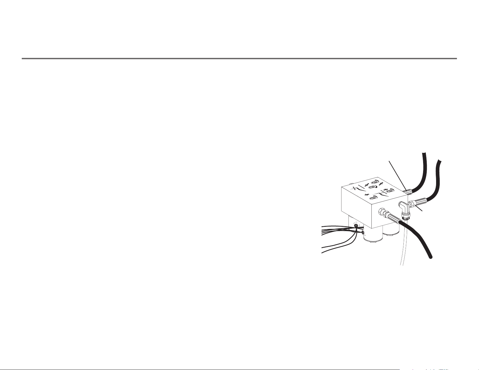
Performer Hydraulic Flow Diagram
From motor/pump
start capacitor
{
Hydraulic
manifold
assembly
Tilt cylinder
Lift cylinder
Vent lines
Pickup tube
Hydraulic fluid reservoir
(check fluid level with
base and back full up)
Hydraulic
pump
motor
NOTE: Use only A-dec fluid P/N 61.0197.00.
MAX
MIN
Page 48

85.0812.00, 2003 PR-47
Performer Potentiometers
Removing the
Helical Drive Shaft
Potentiometer shaft
Back positioning
potentiometer
Clockwise
Follow these steps to remove the limit switch and the
helical drive shaft from the potentiometer shaft.
Task Description
1 Position the chair back full down, loosen the
four screws under the toeboard and remove the
seat upholstery.
2Raise the toeboard assembly and disconnect the
limit switch wiring harness from the limit switch.
3Remove the limit switch mounting screws
and limit switch from the bracket. Lower the
toeboard, if necessary, to access the rear mounting
screw. Do not bend the switch arm.
4Remove the bracket mounting screws. Manually
raise or lower the toeboard for access if necessary.
5Remove helical drive shaft from potentiometer
shaft. While holding the helical shaft, reach
underneath the chair to the base of the backrest.
Grasp the bracket and pull away from the
helical shaft.
6Remove the helical drive shaft from the chair by
moving it toward the chair backrest and then
slightly to the side to dislodge it from the holder
and guide.
Limit switch
mounting screws
Potentiometer shaft
Urethane tubing 3/8" OD
Helical drive shaft
Page 49

85.0812.00, 2003 PR-48
Performer Potentiometers
Base Positioning Potentiometer and Limit Switch
2
1
3
Item # Part Number Description
1 041.372.00 Potentiometer,
5K Ohm, +20%, 1W, w/nut
2 044.049.01 Limit switch, modified
3. 61.1295.00 Gear, 24 pitch, 30 tooth
Replacing Base Positioning Potentiometer,
Limit Switch and Gear
CAUTION
Ensure that the large drive gear is secure (does not
turn) on the head of the bolt. Do not over tighten
(or “bottom” out) the setscrew.
Page 50

85.0812.00, 2003 PR-49
Performer Potentiometers
Follow these steps to adjust the base positioning potentiometer.
Task Description
1 Remove the motor/pump cover and position
the chair base down.
2Remove the mounting screw.
3Turn the potentiometer gear clockwise until
it stops.
4Align the potentiometer assembly, then
turn the potentiometer gear counterclockwise
two teeth (relative to one tooth on the large
drive gear).
5 Ensure all electrical connections to the limit
switch and positioning potentiometer are complete.
6Raise the chair base while observing the two gears for binding.
Adjusting the
Base Positioning
Potentiometer
Limit
switch
Large drive gear
Potentiometer gear
Positioning
potentiometer
Mounting screw
Clockwise
Counterclockwise
Adjusting the Base Positioning Potentiometer
NOTE: Do not raise the base to full up until you have
checked the base up limit switch for proper
adjustment (see
Adjusting the Base Up Limit Switch
).
CAUTION
Ensure that the large drive gear is secure (does not
turn) on the head of the bolt. Do not over tighten
(or “bottom” out) the setscrew.
Page 51

85.0812.00, 2003 PR-50
Performer Potentiometers
Adjusting the
Base up
Limit Switch
Limit switch
Switch arm
Actuator
Clamping
screws
Mounting bracket
NOTE:Positioning potentiometer omitted for clarity.
23"
584mm
To adjust the base up limit switch, do the following.
Task Description
1 Remove the motor/pump cover.
2 Loosen the two screws clamping the limit
switch to the mounting bracket.
3 Position the chair base up until the distance
from the floor to the base of the upper chair
casting is 23" (584mm).
4 Push the limit switch against the
actuator on the drive gear until the switch
opens (clicks).
NOTE:For correct limit switch actuation, the
actuator tab on the large gear should be at
the 5:30 clock position when the chair is full
base down.
5Tighten the clamping screws, making sure they
do not hit the gear.
6Lower the chair base down until the limit
switch has closed, then raise the chair full base
up. Check the distance from the floor to the base
of the chair casting to ensure it is 23" (584mm).
Page 52

85.0812.00, 2003 PR-51
Performer Auto-Positioning
Programming
the Chair
Follow these steps to set the auto-positioning for the chair.
Task Description
1Use the footswitch or touchpad to set the chair at the desired position
for base and back.
2Press and release the program button.
Result: You will hear a single beep.
3Within four seconds, press an automatic position button (0, 1, 2, or 3)
on the footswitch or touchpad to store the chair position. On an
8-function footswitch, move the actuator to the desired position.
Result: You will hear three beeps confirming that
the function has been programmed.
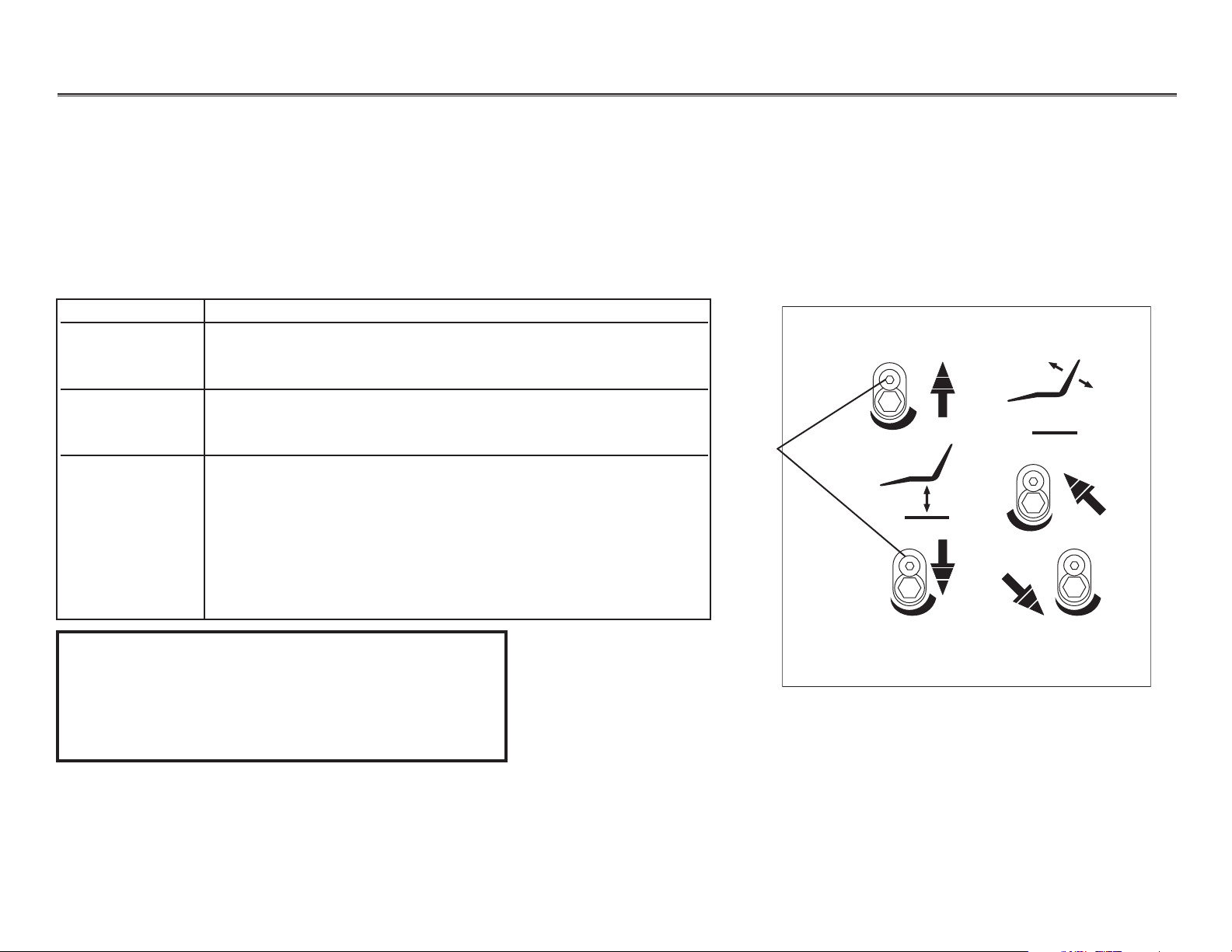
Performer III Touchpad
8-Button Footswitch
Pre-position (1)
Pre-position (2)
Entry/Exit (0)
Cuspidor/return,
last position, or
pre-position (3)
Program
button
Program
button
Base up
Back down
Back up
Base down
Programmable
position (1)
Programmable
entry/exit (0)
Programmable
position (2)
Cuspidor
return (3)
Base up
Back up
Base down
Back down
Replacement membrane P/N 61.3048.00
NOTE: PCBs manufactured before 1994, do not beep.
Test the programming by trying it.
2
3
1
0
Page 53

85.0812.00, 2003 PR-52
Performer Function 3 Programming
Programming
Function 3
Function
Programming
Cuspidor/Return
NOTE: Chairs with S/N J467728
and later are factory set with
function 3 as cuspidor/return
Last Position
Programmable Position
NOTE: Chairs up to S/N J467727
are factory set with function 3
as a programmable position
Description
Switches 1 and 2 are OFF.
Switch 1 is ON and switch 2 is OFF.
Go back and forth between two
positions by momentarily moving the
righthand actuator on the 8-function
footswitch to position 3 or pressing
number 3 on the touchpad or 8-button
footswitch.
Switch 1 is OFF and switch 2 is ON.
Move the chair to the desired position.
Press and release the program button.
After the beep, push button 3 on the
touchpad or 8-button footswitch or
move the actuator to position 3 on the
8-function footswitch. The single beep
confirms the position is programmed.
Used to raise the chair back to a
programmable upright position
providing the patient access to the
cuspidor. Momentarily pushing button 3
on the touchpad or 8-button footswitch,
or moving the actuator to position three
on the 8-function footswitch, returns the
back to the previous position.
Anon-programmable position that
simply moves the chair base and back to
their previous positions.
This option is used to set the base and
back to a predesignated
position. It allows this function to be
programmed like 0, 1, and 2.
ON
Switch 2
Function 3 DIP Switch
before 2000
Switch 1
Before 2000
1 2
ON
Page 54

85.0812.00, 2003 PR-53
Performer Function 3 Programming
Switch 1
Switch 2
Function 3 DIP Switch
after 2000
Programming
Function 3
Function
Programming
Cuspidor/Return
Last Position
Programmable Position
Description
Both switches 1 and 2 are OFF.
Switch 1 is ON and switch 2 is OFF.
Go back and forth between two
positions by momentarily pushing the
right hand rocker button to position 3
or pressing number 3 on the touchpad.
Switch 1 is OFF and switch 2 is ON.
Move the chair to the desired position.
Press and release the program button.
After the tone, push button 3 on the
touchpad or footswitch or move the
actuator to position 3 on the 8-function
footswitch. The audible tone confirms
the position is programmed.
Used to raise the chair back to a
programmable upright position
providing the patient access to the
cuspidor. Momentarily pushing button 3
on the touchpad or 8-button footswitch,
or the actuator to position 3 on the
8-function footswitch will return the
back to the previous position.
Anon-programmable position that
simply moves the chair base and back to
their previous positions.
Used to set the base and back to a
predesignated position.
After 2000
Page 55

85.0812.00, 2003 PR-54
Performer Floor Box
Floor Box
1
2
3
Item # Part Number Description
1 33.0048.03 Master On/Off (3-way) toggle valve
2 041.582.00 12 volt green light; not installed on all floor boxes
(replace as a complete assembly)
3 041.512.00 Light intensity rocker switch
(replace as a complete assembly)
90.1045.00 Kit, intensity light switch cable.
Page 56

85.0812.00, 2003 PR-55
Performer Flow Diagram
Item # Part Number Description
1 24.0469.00 Air filter/regulator valve
2 34.0033.00 Water shutoff valve, air operated
3 025.052.00 Pinch clamp
4. 33.0048.03 Master On/Off (3-way) toggle valve
Floor Box
1
2
Handpiece
control
Cuspidor/
Assistant’s
Foot control
Air manual shutoff valve
Water manual shutoff valve
NOTE: Do not connect the water shutoff valve
(34.0033.00) when the unit does not include a
cuspidor or a water quick disconnect.
After December 1995
3
4
2
30
20
1
10
0
34
50
40
60
70
90
100
0
psi
2
kg/cm
5
80
6
Page 57

85.0812.00, 2003 PR-56
Performer Flow Diagram
Item # Part Number Description
1 24.0372.00 Air regulator valve
2 34.0033.00 Water shutoff valve, air operated
3 025.052.00 Pinch clamp
4 33.0048.03 Master On/Off (3-way) toggle valve
Floor Box
1
2
Handpiece control
Cuspidor/
Assistant’s
Foot control
Air manual shutoff valve
Water manual shutoff valve
NOTE: Do not connect the water shutoff valve (34.0033.00) when the
unit does not include a cuspidor or a water quick disconnect.
After December 1995
(only with the International Performer I chair)
3
4
34
50
40
60
2
20
1
5
30
70
80
6
90
10
100
0
psi
2
7
0
kg/cm
Page 58

85.0812.00, 2003
Performer Flow Diagram
Item # Part Number Description
1 90.1027.03 Automatic moisture separator
2 24.0469.00 Air filter/regulator valve
3 34.0037.00 Air shutoff valve, air operated
4 34.0033.00 Water shutoff valve, air operated
5 025.052.00 Pinch clamp
6 33.0048.03 Master On/Off (3-way) toggle valve
Floor Box with Automatic Moisture Separator
1
2
Handpiece control
Cuspidor/
Assistant’s
Gravity drain
Dump tube
Air manual shutoff valve
Foot
control
Water manual shutoff valve
NOTE: Do not connect the water shutoff valve (34.0033.00) when the
unit does not include a cuspidor or a water quick disconnect.
After December 1995
3
6
4
5
Moisture
separator
PR-57
34
50
40
60
2
30
70
20
1
90
10
100
0
psi
2
7
0
kg/cm
5
80
6
Page 59

85.0812.00, 2003 PR-58
Performer Flow Diagram
Item # Part Number Description
1Moisture separator
2 24.0469.00 Air filter/regulator assembly
3 34.0033.00 Water shutoff valve, air operated
4 025.052.00 Pinch clamp
5 33.0048.03 Master On/Off (3-way) toggle valve
Floor Box with Manual Moisture Separator
1
2
Handpiece control
Cuspidor/
Assistant’s
Air manual shutoff valve
Water manual
shutoff valve
Foot control
NOTE: Do not connect the water shutoff valve (34.0033.00) when the
unit does not include a cuspidor or a water quick disconnect.
After December 1995
3
5
4
Moisture
separator
34
50
40
60
2
30
20
1
10
100
0
psi
0
kg/cm
5
70
80
6
90
2
7
Page 60

85.0812.00, 2003 PR-59
Performer Flow Diagram
Item # Part Number Description
1 24.0372.00 Air regulator valve
2 34.0033.00 Water shutoff valve, air operated
3 025.052.00 Pinch clamp
4 33.0080.01 Master On/Off (3-way) toggle valve
with 4" barbs
Floor Box
1
2
Handpiece control
Cuspidor/
Assistant’s
Air manual shutoff valve
Water manual shutoff valve
Foot control
NOTE: The 1/4" ID pilot air tubing (yellow with red dashes)
was changed to 1/8" ID pilot air tubing (yellow with
red stripe) in all units built after December 1995.
Before January 1996
3
4
34
50
40
60
2
30
20
1
10
0
5
70
80
6
90
100
0
psi
2
7
kg/cm
Page 61

85.0812.00, 2003 PR-60
Performer Floor Boxes
Item # Part Number Description
1 90.1027.03 Automatic moisture separator
2 24.0469.00 Air regulator assembly
3 34.0037.00 Air shutoff valve assembly,
air operated
4 34.0033.00 Water shutoff valve assembly,
air operated
5 025.052.00 Pinch clamp
6 33.0080.01 Master On/Off (3-way)
toggle valve with 4" barbs
Floor Box with Automatic Moisture Separator
1
2
Handpiece
control
Cuspidor/
Assistant’s
Gravity drain
Dump tube
Air manual shutoff valve
Foot
control
Water manual
shutoff valve
Before January 1996
3
6
4
5
NOTE: The 1/4" ID pilot air tubing (yellow with red dashes) was changed
to 1/8" ID pilot air tubing (yellow with red stripe) in all units built
after December 1995.
Automatic
moisture
separator
34
50
40
60
5
2
30
70
20
80
1
6
90
10
100
0
psi
2
7
0
kg/cm
Page 62

85.0812.00, 2003 PR-61
Performer Floor Boxes
Item # Part Number Description
1 22.0040.00 Spring
2 33.0031.01 Gray toggle and pin
3 29.0840.00 Stem with o-rings, 3-way
4 030.001.02 O-ring pkg 10
8 33.0048.03 Master On/Off toggle, 3-way
Master On/Off Toggles with Valve, 3-way
Item # Part Number Description
1 023.001.03 Barb, 1/4" pkg 10
2 023.004.03 Barb, 1/8" pkg 10
3 004.005.02 Washer pkg 10
4 004.005.02 Washer pkg 10
5 22.0040.00 Spring
6 29.0840.00 Stem with O-ring, 3-way
7 33.0031.01 Gray toggle with pin
8 33.0080.01 Master On/Off Toggle, 3-way
After December 1995
After January 1996
1
5
6
4
7
1
2
3
2
3
4
5
8
Page 63

85.0812.00, 2003 PR-62
Performer Floor Boxes
Item # Part Number Description
1 026.118.00 Gauge, 0-100 psi
2 24.0182.02 Pre-regulator, 80 psi, relieving
3 030.019.03 O-ring pkg 10
4 24.0234.01 Filter element pkg 6
5 24.0137.01 Gasket, 9-hole pkg 10
6 22.0460.00 Spring conical
7 22.0440.02 Diaphragm pkg 10
8 24.0132.00 Piston with o-ring
9 030.003.02 O-ring pkg 10
Air Filter/Regulator Valve
20
50
10
30
40
60
70
80
90
100
psi
kg/cm
1
9
2
3
24.0469.00
4
5
6
7
8
10
1
0
2
10
20
0
30
40
3
50
kg/cm
psi
100
60
2
7
4
90
70
80
5
6
Page 64

85.0812.00, 2003 PR-63
Performer Floor Boxes
Item # Part Number Description
1 026.118.00 Gauge, 0-100 psi
2 24.0182.02 Pre-regulator, 80 psi, relieving
3 24.0137.01 Gasket, 9-hole pkg 10
4 22.0460.00 Spring conical
5 22.0440.02 Diaphragm pkg 10
6 24.0132.00 Piston with o-ring
7 030.003.02 O-ring pkg 10
Air Regulator Valve
20
50
10
30
40
60
70
80
90
100
psi
kg/cm
1
6
2
3
24.0363.04
4
5
7
1
0
2
10
20
0
30
40
kg/cm
2
7
3
50
psi
100
60
4
90
70
80
5
6
Page 65

85.0812.00, 2003 PR-64
Performer Floor Boxes
Water Shutoff Valve, Air Operated
34.0033.00
5
1
3
2
4
Item # Part Number Description
1 22.0440.02 Diaphragm pkg 10
2 013.032.00 Spring conical
3 24.0132.00 Piston with O-ring
4 030.003.02 O-ring pkg 10
5 24.0137.01 Gasket, 9-hole pkg 10
Page 66

85.0812.00, 2003 PR-65
Performer Floor Boxes
Air Shutoff Valve, Air Operated
5
1
3
2
4
Item # Part Number Description
1 22.0440.02 Diaphragm pkg 10
2 22.0460.00 Spring conical
3 24.0132.00 Piston with o-ring
4 030.003.02 O-ring pkg 10
5 24.0137.01 Gasket, 9-hole pkg10
Page 67

85.0812.00, 2003 PR-66
Performer Floor Boxes
Automatic Moisture Separator
3
1
2
Item # Part Number Description
1 22.0440.02 Diaphragm pkg 10
2 97.0280.02 Filter element pkg 6, 5 micron filtration
(not a bacterial filter)
3 97.0290.00 Bowl with seal
90.1027.30
R
Page 68

85.0812.00, 2003 PR-67
Performer Floor Boxes
Manual Moisture Separator
1
2
Item # Part Number Description
1 97.0280.02 Filter element pkg 6, 5 micron filtration
(not a bacterial filter)
2 97.0290.00 Bowl with seal
Page 69

Wire Voltage Wire
Before Feb 98 After Feb 98
1 Grn/Yel Ground 1 Grn/Yel
2 White 0 VAC 2 Black
3 Orange 10.8/12.1 V 3 White
4 Yellow 10.8 V 4 Orange
5 Violet 12.1 Volts 5 Yellow
6 Red 12.1 Volts 6 Yellow
85.0812.00, 2003
Performer Power Supplies
Wire Voltage Wire
Before Feb 98 After Feb 98
1 Grn/Yel Ground 1 Grn/Yel
2 Black 0 VAC 2 Black
3 Red 24 Volts 3 Gray
4 Orange Not used 4 Open
Front view before
February 1998
Front view before
February 1998
Front side —
test voltage
Wire side —
power supply
White 4-Pin Connector
Wire Voltage Wire
Before Feb 98 After Feb 98
1 Grn/Yel Ground 1 Grn/Yel
2 Brown 0 VAC 2 Black
3 Open Not used 3 Open
4 Open 10.8/12.1 4 White
Front view before
February 1998
Front view before
February 1998
Front side —
test voltage
Wire side —
power supply
Red 4-Pin Connector
Front view before
February 1998
Front view before
February 1998
Front side —
test voltage
Wire side —
power supply
White 6-Pin Connector
80-Watt Power Supply
After January 1998
28.1345.00 115 VAC .80A, 50-60Hz
47.2030.00 100 VAC, .90A, 50-60Hz
47.2031.00 230 VAC, .40A, 50-60Hz
Line voltage selector switch (115V or 230V)
Before February 1998
80-Watt, 115/230 Volt Switchable
Selector Switch Voltage/Fuse Table
Mains Voltage Part Number Description
115 VAC 044.191.00 1.25 A Time Lag Fuse, 5 x 20 mm
Replaces 044.148.00.
230 VAC 044.190.00 630 mA Time Lag Fuse, 5 x 20 mm
Replaces 044.185.00.
WARNING
Make sure the line voltage selector switch is set
on the correct voltage (115V or 230V).
Fuses (see table)
NOTE: No serviceable parts. Replace as a complete assembly.
PR-68
10
A
M
P
230
115
2
30
5
1
1
Page 70

85.0812.00, 2003 PR-69
Performer Foot Control
Foot Control III
9
2
3
6
7
4
8
5
10
1
11
12
Item# Part number Description
1 38.0320.02 Foot control housing
2 38.0075.03 Toggle and pin, dark surf
3 22.0040.00 Spring
4011.016.00 Pin
5 38.0072.03 Valve holder, dark surf
6 38.0066.00 Cap
7 010.056.00 Retainer
8 007.002.00 Setscrew pkg 10
9 33.0138.00 Micro-valve
10 003.078.00 Screws, valve mounting
11 38.0237.00 Retaining ring, internal
*12 38.0760.00 FC3 piston
NOTE:* Parts included in Foot Control III service kit.
** Parts not used in foot controls after 12/96. All parts in the
38.0607.01 are included in Foot Control II service kit.
Page 71

85.0812.00, 2003 PR-70
Performer Foot Control
Foot Control III Valve
Foot Control II Valve
1
2
4
5
6
7
9
8
3
10
11
3
2
12
7
9
8
13
14
NOTE:* Parts included in Foot Control III service kit.
** Parts not used in foot controls after 12/96. All parts in the
38.0607.01 are included in Foot Control II service kit.
*
*
*
*
*
*
*
**
**
Item# Part number Description
*1 38.0760.00 FC3 piston
*2 013.011.00 Spring
*3 10.0440.00 Spring
*4 22.0060.00 Poppet
*5 22.0580.00 Spring
6 22.0050.00 Spring cap
*7 030.012.02 O-ring
*8 22.0778.00 Stem with o-rings
*9 38.0054.02 Diaphragm pkg 10
10 38.0246.00 Stem with E-ring
11 38.0552.00 Ring return, valve stem
12 030.008.02 O-ring pkg 10
**13 023.040.00 Check valve barb, slotted
**14 013.053.00 Spring
Foot Control II &III Valves
*
Page 72

85.0812.00, 2003 PR-71
Performer Flow Diagram
Optional chip blower
or scaler valve
Foot Control II valve
Wet/dry
toggle valve
From air
regulator
To control
head
Foot Control II Cross View
Signal
relay valve
Diaphragm
Foot Control II Valve Assembly
Foot Control II
valve
Signal
relay valve
Exhaust hole
Foot Control I and II were used on A-dec equipment before October 1999. These units are no
longer available.
WARNING
When working on Foot Control II, move the master On/Off toggle to the OFF position and
bleed the system of air pressure. Do this before removing the foot control disc to prevent the
foot control stem from being forcefully ejected from the foot control valve.
Foot Control II
Page 73

85.0812.00, 2003 PR-72
Performer Flow Diagram
Use of Foot Control III began in March 1999. A service kit, P/N 90.0593.00, and an
international conversion kit, P/N 38.1764.00, are available for Foot Control III.
Optional chip blower
or scaler valve
Foot Control III valve
Wet/dry
toggle valve
From air
regulator
To control
head
Foot Control III Cross View
Signal relay
valve
Diaphragm
Foot Control III Valve Assembly
Foot Control III
valve
Signal
relay valve
Exhaust hole
Foot Control III
Page 74

85.0812.00, 2003
Performer Troubleshooting
PR-73
Problem
Action
Audible leakage when foot
control is not being used
Do these steps in the order listed, until the leakage has stopped.
Task Descriptions
1 Check mounting screws in the bottom of the baseplate to make sure they are tight.
• If leakage has stopped, test unit.
• If there is still audible leakage, continue with step 2.
2Remove the cover and check the internal tubings for secure connections.
3 Check for leakage from the exhaust holes on the signal relay valve. If there is leakage, do
the following
•move the master On/Off toggle to the OFF position and bleed the system of air pressure
• inspect the stem and o-rings for debris or defects, and
•inspect the seat for debris or defects.
4Replace any defective parts. Lubricate the o-rings, reassemble and test the foot control.
5 Check for leakage around the diaphragm. If there is leakage, do the following:
•Tighten the two screws securing the signal relay valve to the foot control valve. If there’s
still leakage, replace the diaphragm.
Troubleshooting
Foot Controls
Tips and troubleshooting information are listed in the following charts to assist in diagnosing foot
control problems. These charts do not cover every situation, but do try to include the most common
problems you may encounter. In most cases, it is recommended rebuilding the whole foot control
using the appropriate service kit. This normally solves the problem and saves time.
Page 75

85.0812.00, 2003
Performer Troubleshooting
PR-74
Problem
Action
Audible leakage when foot
control is in use
Complete the following steps in this chart to stop leakage.
Task Descriptions
1Check for a failed diaphragm.
•Tighten the two screws securing the signal relay valve to the foot control valve. If there’s still
leakage, replace the diaphragm.
• If there is still audible leakage, continue with step 2.
2 Check for leakage from the exhaust holes on the signal relay valve. If there is leakage, do
the following:
•move the master On/Off toggle to the OFF position and bleed the system of air pressure
• inspect the stem and o-rings for debris or defects, and
•inspect the seat for debris or defects.
3Replace any defective parts. Lubricate the o-rings, reassemble and test the foot control.
4 Check the outlet barb and tubing on the signal relay valve. Tighten the barb, or replace the tubing.
Page 76

85.0812.00, 2003
Performer Troubleshooting
Problem
Action
Inadequate air flow
Coolant water continues after
release of foot control
Check these in the following order.
Task Descriptions
1 Check the air pressure. If the air pressure drops by more than 15 psi when syringe air button and
foot control are depressed
•Check for pinched foot control tubing.
• Check for a plugged filter in the air filter/regulator (floor box).
•Check for obstructed outlet barb on signal relay valve.
2Move the master On/Off toggle to the OFF position and bleed the system of air pressure.
3 Remove debris and replace any defective parts in the valve assembly. Lubricate the o-rings,
reassemble, and test the foot control.
Check these in the following order.
1Check for a sticky signal relay valve.
2Move the master On/Off toggle to the OFF position and bleed the system of air pressure.
3Remove the signal relay valve, clean and lube the parts, and reassemble.
4Test foot control.
5 Check for a kinked/plugged tubing somewhere between the foot control
relay and the control head.
PR-75
Page 77

85.0812.00, 2003
Performer Troubleshooting
PR-76
Sluggish foot control
Check the following points to test the response on the foot control.
•Move the master On/Off toggle to the OFF position and bleed the system of
air pressure.
•Remove the signal relay valve, clean and lube the parts, and reassemble.
•Test foot control.
Problem
Action
Page 78

85.0812.00, 2003 PR-77
Performer Handpiece Controls
Control Block Assembly With Tubing
Item # Part Number Description
38.1775.00 *Performer control block
service kit
*1 38.0717.00 Water relay valve assembly
2 38.0712.00 Coolant water stem with o-ring
3 030.004.02 O-ring pkg 10
4 38.0713.00 Coolant air stem with o-ring
*5 38.0711.01 Control block diaphragm pkg 5
6 38.0766.02 Flow control screw
with o-ring pkg 5
Handpiece Flush Toggle Valve, 2-Way Momentary
Item # Part Number Description
1 013.055.00 Spring, compression
2 33.0007.00 Disk
3 33.0037.01 Straight pin and toggle
lever, momentary
4 29.0830.00 Stem with o-ring, 2-way
5 030.001.02 O-rings pkg 10
38.0729.00
33.0009.03
1
3
4
1
2
6
3
4
3
2
5
5
3
Unregulated
air ports
Page 79

85.0812.00, 2003 PR-78
Performer Handpiece Controls
Autoclavable Syringe
Item # Part Number Description
23.1011.00 Autoclavable syringe head assembly
23.1150.00 Autoclavable syringe assembly and 7' tubing
23.1099.00 Autoclavable syringe service kit, 2 button
23.1012.00 Autoclavable syringe service kit, soft button
1 23.1232.01 Valve assembly with o-rings, autoclavable
2 23.1193.01 Screw pkg 5
3 013.064.01 Spring pkg 10
4 23.1112.00 Syringe tip retainer, non-locking
5 035.048.01 O-ring pkg 10
6 034.003.01 O-ring pkg 10
7 23.1028.00 Soft button, autoclavable
8 001.002.01 Screw pkg 5
9 23.1021.01 Valve assembly with o-rings pkg 2
10 013.064.01 Spring pkg 10
11 23.1194.00 Two-button valve conversion kit
1
2
3
4
5
6
7
8
9
10
11
Beginning
October 1995
Before
October 1995
Page 80

85.0812.00, 2003
Performer Troubleshooting
Problem
Action
Water leakage at the coolant
water stem
Water leakage at the water relay
valve or handpiece
Audible air leakage at the
flow control screws or coolant
air stem
Water leakage at the
control block
Water leakage at the flow
control screw
Follow these points to stop leakage at the coolant water stem.
• Replace the o-ring.
•Replace the stem.
Replace the valve.
Follow these points to stop leakage at the flow control screws or coolant air stem.
• Replace the o-ring.
•Replace the stem.
Follow these steps to stop leakage at the control block.
Task Description
1 Check to make sure control block assembly screws are tight.
2 Check to make sure all barbs are tight and the washers are not damaged.
3Replace the diaphragm.
4Replace the stem o-rings.
Follow these steps to stop leakage at the flow control screw.
1Replace water relay.
2 Replace the o-ring.
3Replace the stem.
Tips and troubleshooting information are listed to assist in distinguishing control block problems.
Troubleshooting the
Control Block
PR-79
Page 81

85.0812.00, 2003 PR-80
Performer Troubleshooting
Problem
Action
Water leakage from all
handpieces when removed
from holder
Water leakage around flush
toggle valve barbs
No water from flush
toggle valve outlet barb
Follow these steps to stop leakage from handpieces.
Task Description
1 Replace the water relay valve.
2Replace the stem.
3Replace the o-rings on the stem.
Replace the toggle valve.
Follow these steps to flush the toggle valve outlet barb.
1 Check the water supply in the self-contained water bottle.
2Make sure air pressure at the bottle is 40 psi.
3Replace the toggle valve.
WARNING
Turn the master On/Off toggle to the OFF position and bleed system air
pressure before removing the foot control disc to prevent the foot control
stem from being forcefully ejected.
Page 82

85.0812.00, 2003 PR-81
Performer Handpiece Controls
Handpiece Tubing Assembly
Item # Part Number Description
1 98.0262.02 Straight 4-hole fiber-optic tubing
with bulb, 7' (2134 mm)
2 98.0879.00 Straight 4-hole tubing with
Midwest terminal, 7' (2134 mm)
3 98.0882.00 Straight 3-hole tubing with
Borden terminal, 7' (2134 mm)
4 98.0885.00 Straight 4-hole, fiber-optic
tubing, six pin, 7' (2134mm)
Fiber-Optic Bulb
041.317.00
Bulb, Xenon
Bulb terminal
Fiber-optic handpiece tubing
CAUTION
Do not touch the glass of the bulb. Finger oils limit bulb life. If you inadvertently
touch the glass, gently clean with cotton soaked in ethyl or isopropyl alcohol.
1
2
3
4
Page 83

85.0812.00, 2003 PR-82
Performer Handpiece Controls
Syringe Terminal, 2 Barb, Non-Quick Disconnect
Item # Part Number Description
1 030.002.02 O-ring pkg 10
2 23.1015.00 Handle
3 024.155.02 Syringe tubing assembly, straight 7'
1
2
3
23.1208.00
Page 84

85.0812.00, 2003 PR-83
Performer Troubleshooting
Problem
Action
Air or water leakage from one of
the valve assemblies
Air or water leakage from the
syringe nut assembly
No air and/or water from
the syringe
Replace the valve assemblies.
Check the following steps to stop leakage from the syringe nut assembly.
Task Description
1Make sure the syringe nut assembly is properly installed and tightened. Use a 5/32" hex key
to tighten.
2Replace o-rings.
3 Replace the syringe nut assembly.
Check the following steps to fix the syringe.
1 Check to make sure the master On/Off toggle is in the ON position.
2 Check to make sure the air and water supplies are turned ON.
3 Check tubing for kinks or breaks.
Troubleshooting
Syringes
Tips and troubleshooting information are listed to assist in distinguishing syringe problems.
Page 85

85.0812.00, 2003 PR-84
Performer Handpiece Controls
Working with the
Holder Valve Assembly
Holder Valve Activation, Third Handpiece Position
Item # Part Number Description
1 99.0627.00 Micro-valve assembly with tubing
2 004.186.00 Washer
1
2
Screw,
button head
Activation spring
Micro-valve
barbs
Follow these points to activate the third holder position
• Rotate the activation spring counterclockwise.
•Align the spring so it is parallel to the micro-valve barbs
(straight down).
Page 86

85.0812.00, 2003 PR-85
Performer Handpiece Controls
Bitewing Viewer
Item # Part Number Description
1 041.501.00 Fluorescent bulb
4100K 9W
2 76.8001.00 Lens, bitewing viewer
3 76.8100.00 Bitewing viewer, 24 VAC, .5A, 50-60Hz
1
2
3
Page 87

85.0812.00, 2003 PR-86
Performer Handpiece Controls
Tray Holder
Item # Part Number Description
1 39.1380.00 Molded tray holder
2 027.070.00 Knob assembly
3 027.062.00 Knob assembly
2
3
Hex nut
Screw,
button head
Hex nut
Screw, button head
1
Page 88

85.0812.00, 2003
Performer Handpiece Controls
PR-87
Activating the
Holder Valve
Holder Valve Activation
The third handpiece position can be changed from inactive to active by performing a simple adjustment.
Micro-valve
barbs
Activation spring
Step Action
1Rotate the activation spring clockwise
2Align the spring so it is parallel to the micro-valve barbs (straight down)
Page 89

85.0812.00, 2003
Performer Adjustments
Adjusting the
Accessory Tray Holder
Height
Adjusting the
Accessory Tray Holder
Arm Tension
Lift the tray holder to access the height adjustment
ring. Slide the height adjustment ring to the desired
position. Lower the tray holder onto the arm.
Remove the chair seat/toeboard upholstery. Locate the
tray holder arm mounting bolt. Turn the bolt until the
desired tension is achieved.
•Clockwise to tighten
• Counterclockwise to loosen
Reinstall the chair seat /toeboard upholstery.
Tray holder
arm
5/16" hex key
Bolt
Height
adjustment
ring
Tray holder
arm
Tray holder
PR-88
Page 90

85.0812.00, 2003 PR-89
Performer Electrical Diagram
Dental Light
1
2
3
4
NOTE: Dental light connections are made in the cuspidor/assistant’s
housing, the chair junction box, and the floor box. Refer to the
appropriate section for all connector locations.
Item # Part Number Description
1 90.1054.00 Cable assembly
2 90.1039.00 Toggle switch kit
3 041.513.00 12 volt, 55-watt halogen bulb
4 90.1045.00 Kit, Light intensity rocker switch
with cable
Page 91

85.0812.00, 2003 PR-90
Performer Illustrated Parts
Dental Light
Item # Part Number Description
1 004.207.00 Washer, flat
2 013.100.00 Spring
3 016.054.00 Bearing, thrust
4 28.1172.00 Compression bolt
5 016.053.00 Washer, thrust
6 28.1175.01 Washer, thrust
7 90.1039.00 Toggle switch kit
8 28.1188.00 Handle, On/Off switch
9 28.1289.00 Bulb socket and insulation
10 041.513.00 12 volt, 55-watt halogen bulb
11 28.1213.00 Bulb cap assembly
12 28.1166.00 Reflector shield
1
2
4
6
8
7
3
9
10
11
12
5
Horizontal adjustment
screw
Vertical tension
adjustment screw
Focus adjustment screw
Page 92

85.0812.00, 2003 PR-91
Performer Adjustments
Turn the vertical tension adjustment screw
clockwise to increase tension. Turn counterclockwise
to decrease tension.
Turn the horizontal tension adjustment screw
clockwise to increase tension. Turn counterclockwise
to decrease tension.
Loosen the focus adjustment screw. Move the bulb socket in
or out of the reflector housing until the light is focused.
Tighten the focus adjustment to fully secure the bulb socket.
Increase tension
Decrease tension
Vertical tension
adjustment screw
5/16" hex key
Increase tension
Decrease tension
Horizontal tension
adjustment screw
5/16" hex key
Adjusting the Light
Head Vertical Tension
Adjusting the Light
Head Horizontal Tension
Focusing the Light
Page 93

85.0812.00, 2003 PR-92
Performer Adjustments
Adjusting the Flexarm
Adjusting the Flexarm
Trav el (Limit Up)
Adjusting the Flexarm
Trav el (Limit Down)
Remove the screw from the rear end cap, then remove the front
end cap and cover from the arm. Using a 1/2" open end
wrench, turn the tension adjustment nut inside the arm. If the
arm moves too easily, it tends to drift up or down by itself,
tighten the nut by turning it clockwise. If the arm tension is too
stiff, loosen the nut by turning it counterclockwise.
The upward motion of the flexarm can be adjusted by adding a
Travel Stop Limit Kit (P/N 90.1044.00). To order this kit contact
A-dec customer service at 1-800-547-1883.
The downward motion of the flexarm can be adjusted by adding
a Travel Stop Limit Kit (P/N 90.1044.00). To order this kit contact
A-dec customer service at 1-800-547-1883.
Counterclockwise
(loosen)
Adjustment
nut
Clockwise
(tighten)
Adjustment
nut
Setscrew
Stop
Adjustment
nut
Setscrew
Stop
Brass
nut
Page 94

85.0812.00, 2003
Performer Troubleshooting
Problem
Action
No light
Dim light
Follow these steps to fix the dental light.
Task Description
1Make sure the system is plugged in and turned ON.
2Check the 80-watt power supply for power.
3 Check the bulb, replace if necessary.
4 Check all the light wire harness connections.
5 Check voltage intensity and On/Off switches.
6 Check the voltage at the bulb.
Follow these steps to fix the dental light.
1Check cleanliness of bulb, shield, and reflector.
2 Check the bulb, replace if necessary.
3 Check intensity switch voltages.
4Check 80-watt power supply output voltage.
Troubleshooting
Dental Lights
Tips and troubleshooting information are listed to assist in distinguishing dental light problems.
PR-93
Page 95

85.0812.00, 2003
Performer Flow Diagram
Cuspidor for Central Vacuum
Solids collector
Item # Part Number Description
1 12.0910.06 Autoclavable saliva ejector
with 7' tubing
211.1025.02 Autoclavable HVE with
7' tubing
Floor box
1
2
Cuspidor (Single Operatory Vacuum)
Solids collector
Item # Part Number Description
1 12.0910.06 Autoclavable saliva ejector
with 7' tubing
2 12.1132.00 Autoclavable HVE with 7' tubing
3 12.1122.00 Auto-electric holder, 3-position
(after Nov 1997)
4 12.1071.00 3-way valve assembly (before Nov 1997)
Floor box
1
2
3
4
PR-94
Page 96

85.0812.00, 2003 PR-95
Performer Flow Diagram
Cuspidor with Air Saliva Ejector
Item # Part Number Description
1 12.0910.06 Autoclavable saliva ejector
with 7' tubing
2 12..1070.00 2-way valve assembly
311.1105.00 Air saliva ejector
Floor box
1
3
2
Cuspidor with Water Saliva Ejector
Item # Part Number Description
1 12.0910.06 Autoclavable saliva ejector
with 7' tubing
2 12..1073.00 2-way valve assembly
3 12.0500.00 Water saliva ejector
Floor box
Cuspidor bowl rinse and
cup fill manifold
1
3
2
Page 97

85.0812.00, 2003 PR-96
Performer Flow Diagram
Cuspidor with Air Saliva Ejector, Air Vacuum
Generator and AVS
Item # Part Number Description
111.1100.00 Air vacuum generator
211.1127.01 Performer AVS with 7' tubing
3 12.0910.06 Autoclavable saliva ejector
with 7' tubing
4 12.1070.00 2-way valve assembly
511.1105.00 Air saliva ejector
Floor box
1
3
4
5
2
Page 98

85.0812.00, 2003 PR-97
Performer Cuspidor and Assistant’s Instrumentation
Performer Cuspidor Assembly
Item # Part Number Description
1 12.0985.00 Cup fill spout
2 12.0986.00 Bowl rinse spout
3 76.2011.00 Cuspidor/bowl assembly
4 75.0035.01 Bowl screen pkg 5
5 12.0991.00 Drain seal
6 12.1020.00 Holder, 3-position, fixed
12.1056.00 Holder, 4-position, fixed
99.0584.00 Holder, single, assistant’s, fixed
12.1207.00 Holder, 4-position, rotating
12.1210.00 Holder, 3-position, rotating
1
2
4
3
5
6
NOTE: The spout(s) is not fully seated in the housing.
Make sure the spout is fully installed.
Page 99

85.0812.00, 2003 PR-98
Performer Cuspidor and Assistant’s Instrumentation
Cuspidor Bowl Rinse and Cup Fill Manifold
1
2
3
4
5
67
Item # Part Number Description
1 12.0977.01 Activator rod pkg 2
2 12.1016.00 Clip
3 12.0988.00 Water spout seal
4 013.004.00 Spring
5 010.045.02 Retaining ring, internal pkg 10
6 12.0983.00 Diaphragm retainer
7 12.0982.01 Diaphragm, water manifold
Page 100

85.0812.00, 2003
Performer Troubleshooting
Problem
Action
Spout(s) eject from
cuspidor housing
Cup fill or bowl rinse
run continuously
Water leaks from the spout tips
or from the cuspidor housing
Water seeps around the spouts
No water
The spout(s) is not fully seated. Make sure the spout is fully installed and test again.
Follow these points to stop the cup fill or bowl rinse from continuously running.
•Replace the activator rod, if bent.
• Replace the spring.
Follow these points to stop leakage from the spout tips or cuspidor housing.
•Replace the diaphragm(s).
• Replace the spring(s).
Follow these points to stop leakage from the spout.
• Check the spouts to make sure they are fully seated.
• Replace the water spout seals.
Follow these steps to correct a no water problem.
Task Description
1Make sure the water shutoff valve is fully turned ON.
2Check supply lines and pinch valves.
3Check for plugged passages.
Tips and troubleshooting information are listed to assist in distinguishing cuspidor problems.
Troubleshooting
Cuspidors
PR-99
 Loading...