

Page 1
Lisa
Sterilizer
MB17
Service
Guide
About
the
Lisa
Sterilizer
Section 1 —
About
Characteristics
the
Lisa
Developed,
for
small
Totally
Compact
Patented
-
Low
- 8 to
Quick
5
fractionated
-
Pulsed
Independent
Optimized
Maximum
Interactive
Simple
Entirely
Evolutionary
Single
produced
water
Class B cycles.
sterilizer,
«2CS » pneumatic
water
consumption: 7 to
12
cycles
cycles:
vacuum
steam
energy
absorbed
user-friendly
to
use
controlled
software.
piece
stamped
Sterilizer
and
tested
steam
sterilizers.
without
without
30
minutes
pre-vacuum.
drying.
generator.
management
power:
and
safe.
by
any
system
refilling
(276°F/135.5°C-4
touchscreen.
microprocessor.
stainless-steel
according
external
:
12
oz/cycle
or
draining.
(0.5
2100
W.
chamber.
to
the
European
tank
or
connections.
(.2
to
minutes).
kwh/cycle).
Norm
PrEN
.35
liters/cycle).
13060
85.0815.00
Reversible
or
vertical.
Optional
Refilling
Electric
door
Easy
touchscreen.
the
Warranty:
tray
printers.
and
double
gasket.
accessibility
Up
support: 5 trays
draining
door
to
locking
for
service.
2
years
possible
or
2000
horizontal
during
system
Test
and
functions
cycles
or 3 cassettes
the
cycle.
parallel
whichever
positioning
available
on
comes
horizontal
of
the
first.
Page 2
About
the
Lisa
Sterilizer
Lisa
Sterilizer
MB17
Service
Guide
Cycle
Power
External
Weight
Operational
Noise
Average
Maximum
Pressure
Capacity
Diameter
Depth
Maximum
Maximum
Usable
Capacity
Dimensions
Performance
Empty
Level
Chamber
Dimensions
Weight
Chamber
Pressure
Temperature
Space
Design
MB17
Power
Power
Rated
Current:
17.5
(W) x 16.1
445
(W) x 410
105.8
lb. / 48
108.0
lb. / 49
38
dB
53
dB
18.0
quarts / 17
9.84
in. / 250
13.77
in. / 350
34.8
psi / 2.4
280
°F / 138
12.7
quarts / 12
7.67
(W) x 8.07
195
(W) x 205
Type:
Microprocessor-controlled
Requirements:
Consumption:
9.2A
(H) x 20.5
(H) x 520(D)
kg
kg
liters
mm
mm
bar
°C
liters
(H) x 11.81
(H) x 300
Single
Maximum
(D)
(inches)
(mm)
(D)
(D)
(mm)
Phase
2100
W
(inches)
-
steam
230
VAC
sterilizer,
(3)
+/-
10% / 50-60
Class B cycles
Hz / 10A
Water
Main
Used
Air
External
Data
Tanks
Capacity
Water
Vent
Filter
Connections
Capture
Capacity
Devices
3.7
quarts / 3.5
4.2
quarts / 4.0
0.3
um
The
MB17
optional
Custom
used
kit.
DP40
liters
liters
water
dot
matrix
tank
printer
can
be
plumbed
to
automatically
drain
with
on
85,0815.00
Page 3
Lisa
Sterilizer
A
Pressure
(psi)
MB17
Service
e...
Guide
About
the
Lisa
Sterilizer
2
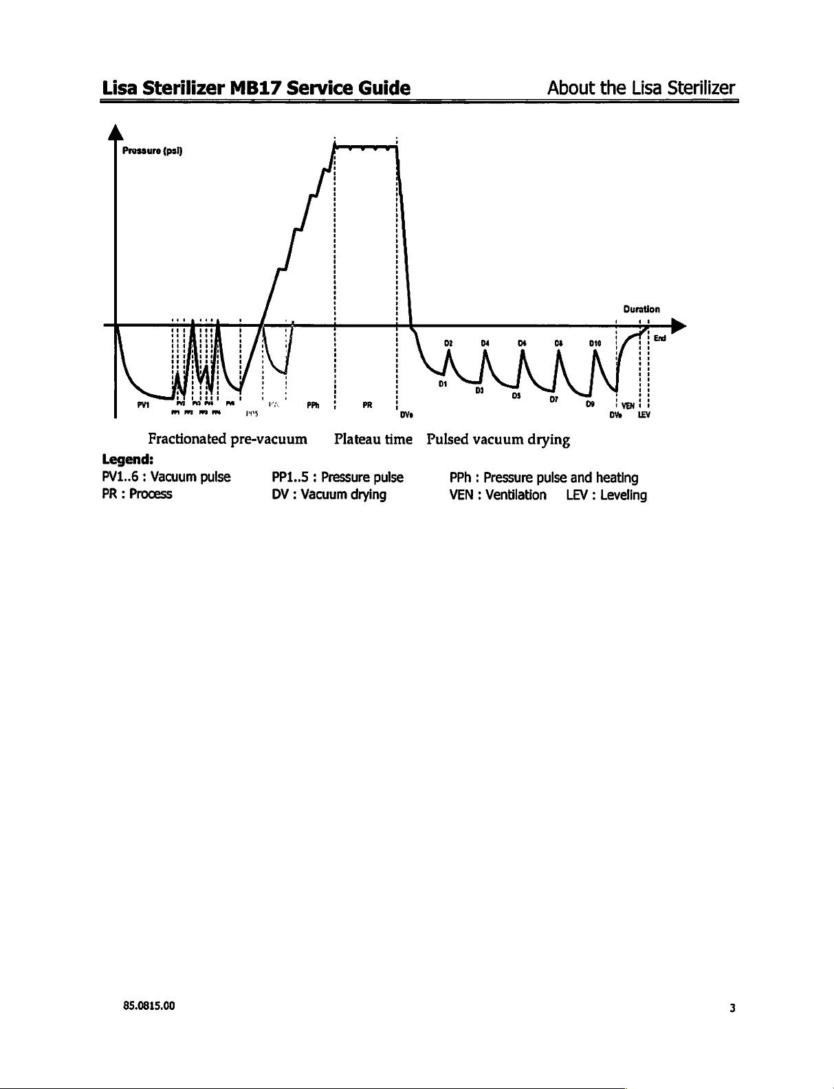
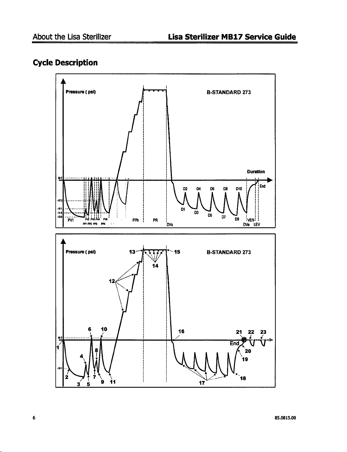
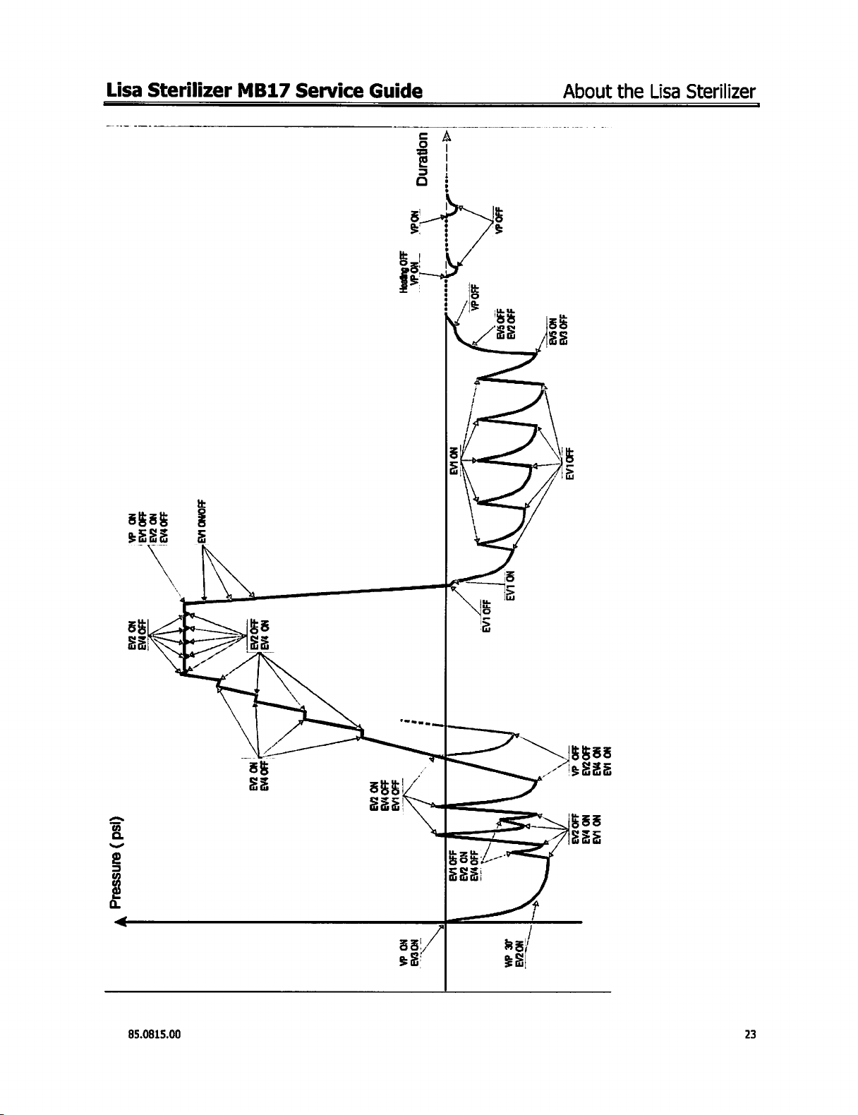
Fractionated
Legend:
:
PV1..6
PR : Process
Vacuum
pre-vacuum
pulse
Plateau
PP1..5 : Pressure
DV : Vacuum
time
pulse
drying
Pulsed
vacuum
PPh : Pressure
VEN : Ventilation
drying
pulse
and heating
LEV : Leveling
85.0815.00
Page 4
About
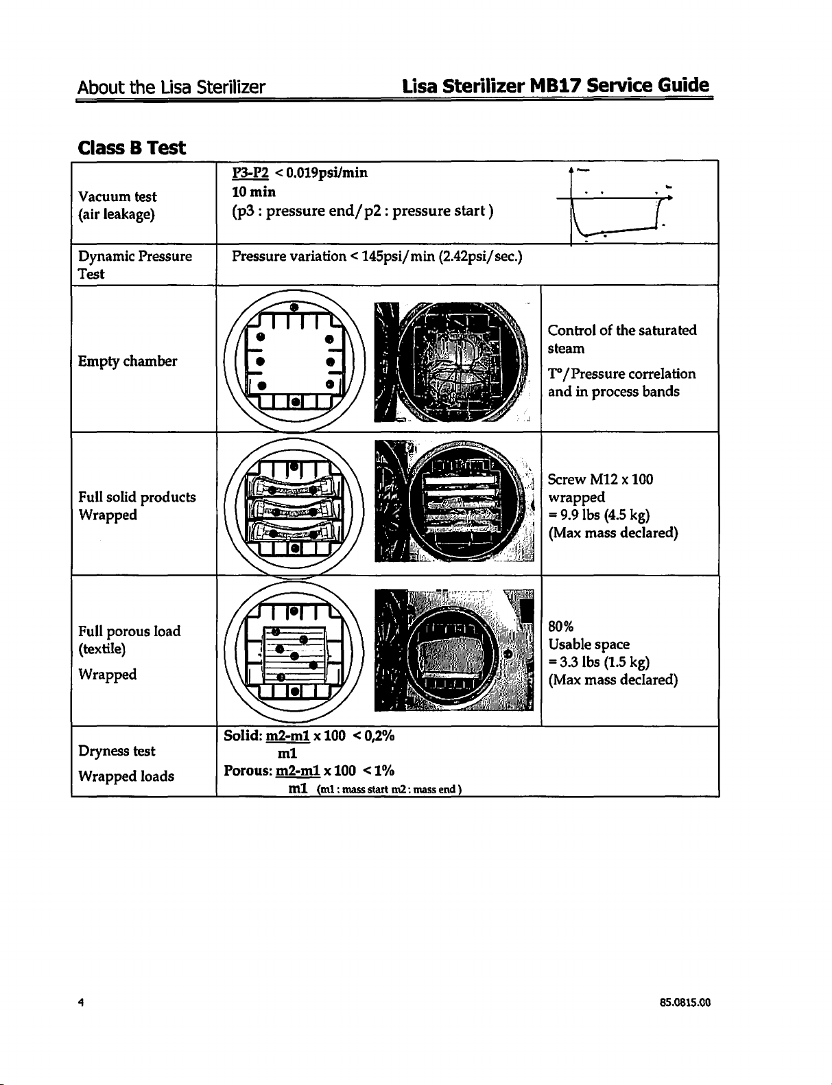
Class B Test
Vacuum
{air
the
test
leakage)
Lisa
Sterilizer
P3-P2 < 0.019psi/min
10
min
(p3 : pressure
Lisa
Sterilizer
end/p2 : pressure
start)
M
B17
Service
Guide
yr
Dynamic
Test
Empty
Full
Wrapped
Full
(textile)
Wrapped
chamber
solid
porous
Pressure
products
load
Pressure
variation < 145psi/
min
(2.42psi/
sec.)
Control
steam
T°/
and
Screw
wrapped
=
(Max
80%
Usable
=
(Max mass
of
Pressure
in
process
M12 x 100
9.9
Ibs
mass
space
3.3
Ibs
(4.5
(1.5
the
saturated
correlation
bands
kg)
declared)
kg)
declared)
Dryness
Wrapped
test
loads
Solid:
Porous:
m2-m1 x 100 < 0,2%
m1
m2-m1 x 100
ml
(m1:
mass
<1%
start
m2:
mass
end)
85.0815.00
Page 5
Lisa
Sterilizer
MB17
Service
Guide
About
the
Lisa
Sterilizer
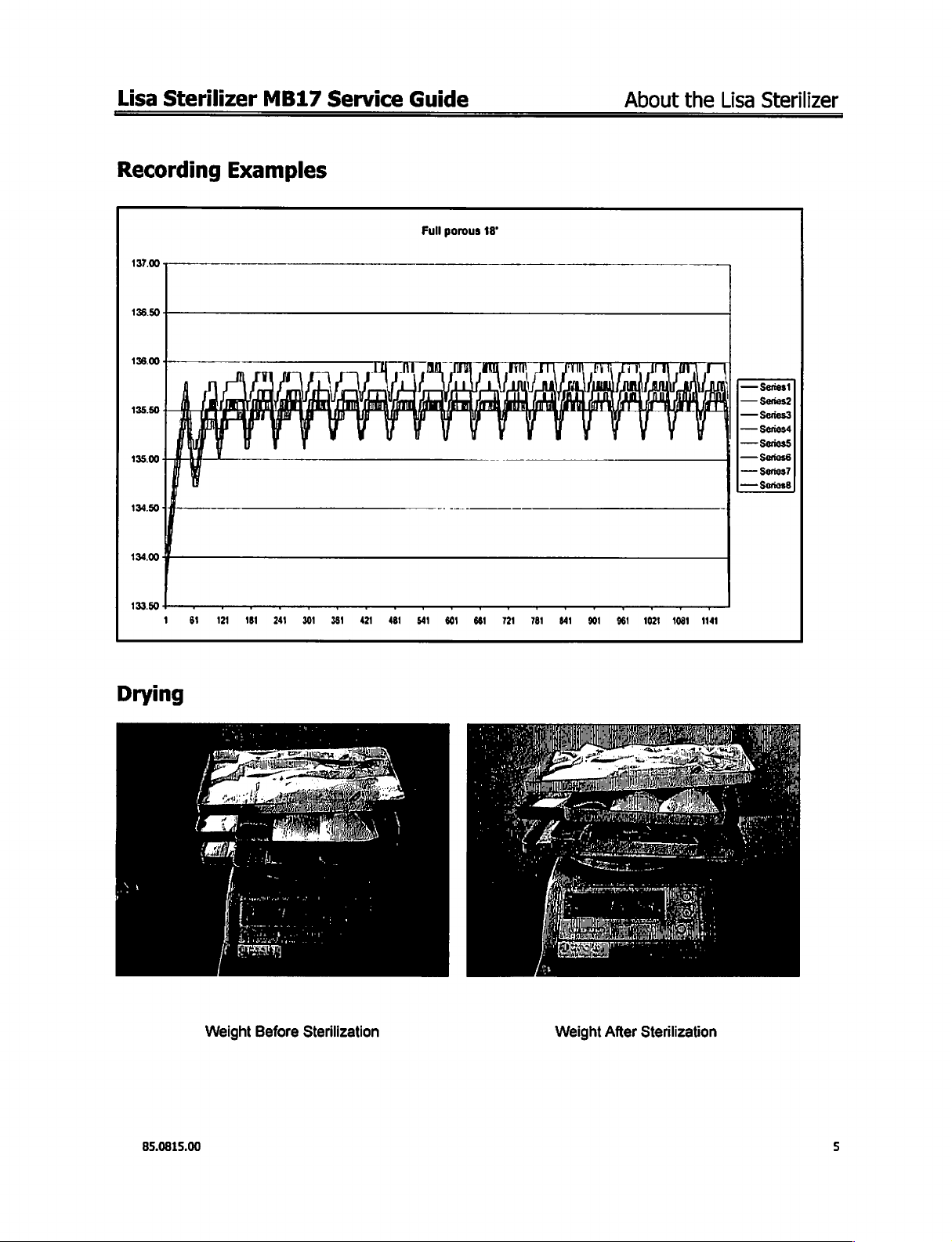
Recording
137.00
434.00
1
6
Examples
121
181
240
301
3581
421
Full
porous
18°
—
Series!
—
$01052
—
561653
—
$67054
—
Seriess
<
—
Serios?
——
$01088
4
541
601
661 721
м
м
901 961
1021
1001
1141
Weight
85.0815.00
Before
Sterilization
Weight
After
Sterilization
5
Page 6
About
the
Lisa
Sterilizer
Lisa
Sterilizer
MB17
Service
Guide
Cycle
Description
A
Pressure ( psi)
mb.
maj-
ot
4116
.
139
GRR
c
ho:
Dvs
02
Di
oq
03
B-STANDARD
pe
os
DS
DI
Do
09
273
Buration
i/
i | :
НОЕ
ivENi
OVe
一
-一
1:99
ii
ii
LEV
>
À
Pressure ( psi)
+
*—
15
16
之
M
SV
B-STANDARD
1
Ş
M
47
End
v
21
273
LA
\
19
18
22
20
23
>
6
85.0815.00
Page 7
Lisa
Sterilizer
MB17
Service
Guide
About
the
Lisa
Sterilizer
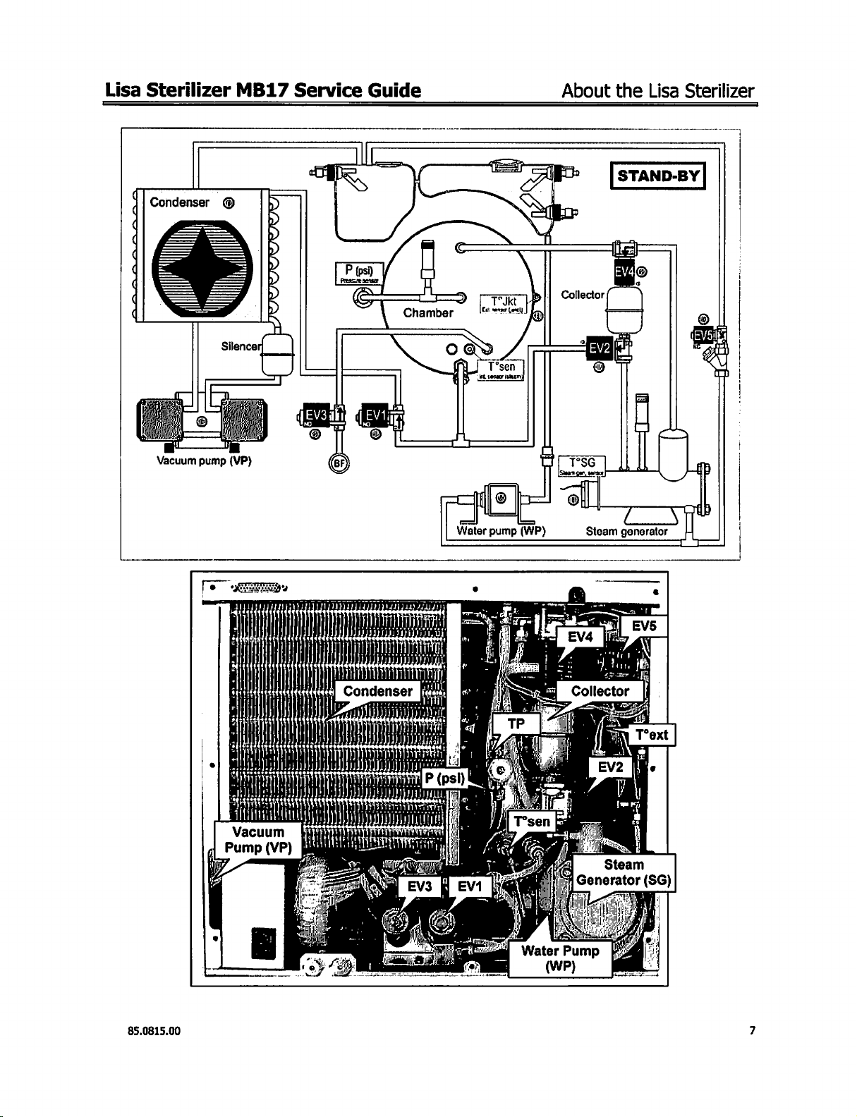
Condenser | Φ
(VP)
Vacuum
pump
Water
pump
(WP)
Steam
STAND-BY
generator
1
|
)
Hi
ΙΙ
01
В
ï
Il
Tİ
M
Peo,
00141
fl
|
m
0
NS
Generator
ÉS
(SG
85.0815.00
Page 8
About
d
q
di
4
(
the
Lisa
Condenser
|
Vacuum
A
É
Sterilizer
©
Silencer
®
pump
(VP)
Lisa
Sterilizer
E
MB17
Collector
Service
HEA / SEL
iz
3016
一
Guide
"60006
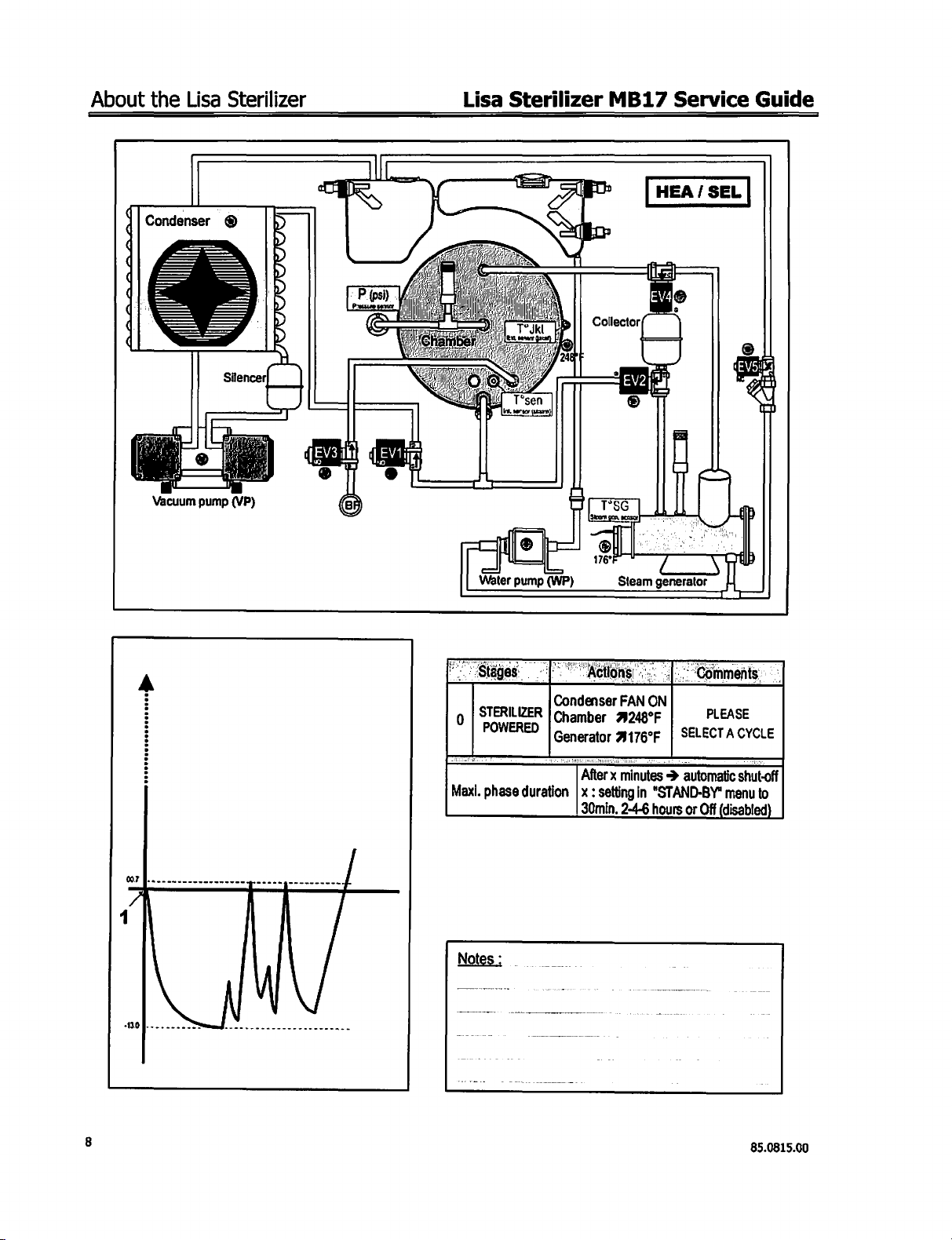
STERILIZER
|
o
POWERED
|
Maxi.
phase
|
duration | x : settingin
AC
ON
Condenser
Chamber
|
Generator
OE
|
FAN
2248ºF
4176°F
After x minutes > automatic
30min.
"STAND-BY"
2-4-6
hours
|
jnments
PLEASE
SELECTA
or
Off
(disabled)
CYCLE
shut-off
menu
to
8
85.0815.00
Page 9
Lisa
Sterilizer
|
Condenser.
LS
LS
RS
MB17
@
Service
Guide
About
the
CYCLE
Lisa
Sterilizer
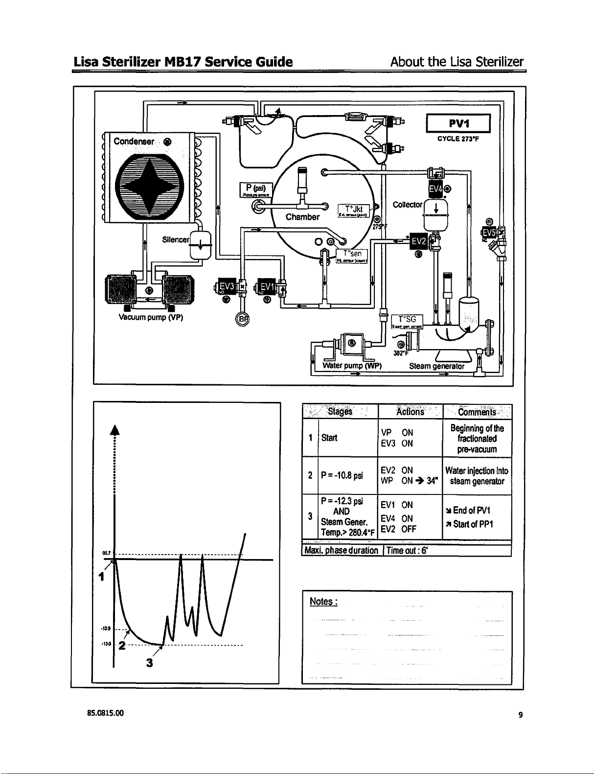
PV1
273°F
dd
Vacuum
©
pump
Silencer
(VP)
1 | Start
=.
2
(P=-10.8psi
P=-12.3
3
|
AND
Steam
Temp.>
Maxi.
phase
VP
EV3
。
|EV2
(wp
psi
vi
Gener.
280.4°F
|
EV2
duration | Time
ON
ON
ON
ON-
ON
OFF
out:
Beginning
fractionated
pre-vacuum
Water
34° | steam
w
End
a
Start
6
of
the
injection
into
generator
of
PV1
of
PP1
85.0815.00
Notes
:
Page 10
About
the
Lisa
Sterilizer
Lisa
Sterilizer
MB17
Service
Guide
(
(
q
(
(
Condenser
Vacuum
A
©
pump
@
Silencer,
(VP)
ea
=
Chamber
TIR
"==
o
ΜΜΕ
|
!
@
|
Water
pump
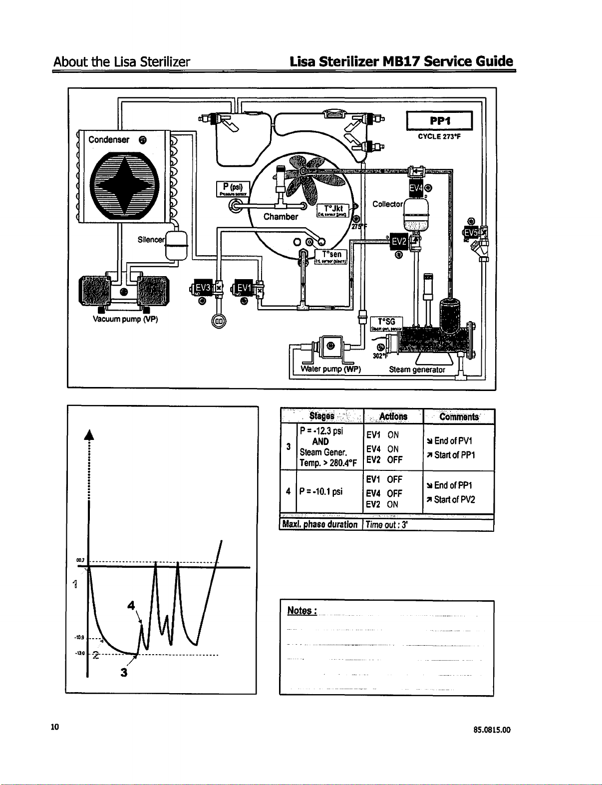
, . Stages]
P = -12.3
3
|.
Steam
Temp. > 280.4ºF
4
|P=-10.1
Maxl,
phase
psi
AND
Gener.
psi
duration
PP1
CYCLE
273ºF
je
Collector
=
©
TSG
®
Steam
ON
OFF
OFF
OFF
ON
out:
κ
generator
—
à
End
A
Start
à
End
A
Start
of
PV
of
of
PP
of
218
=
|||
|
|
8
302°
(WP)
Actions | Comments’
va
EV2
EV1
EVA
EV2
|
Time
©
내
a
PP4
PV2
Notes:
_
10
_
ーー
85.0815.00
Page 11
Lisa
Sterilizer
MB17
Service
Guide
About
the
Lisa
Sterilizer
Condenser
>
へ
ュー
ュー
ュー
ュー
ヘー
Vacuum
pump
@
(VP)
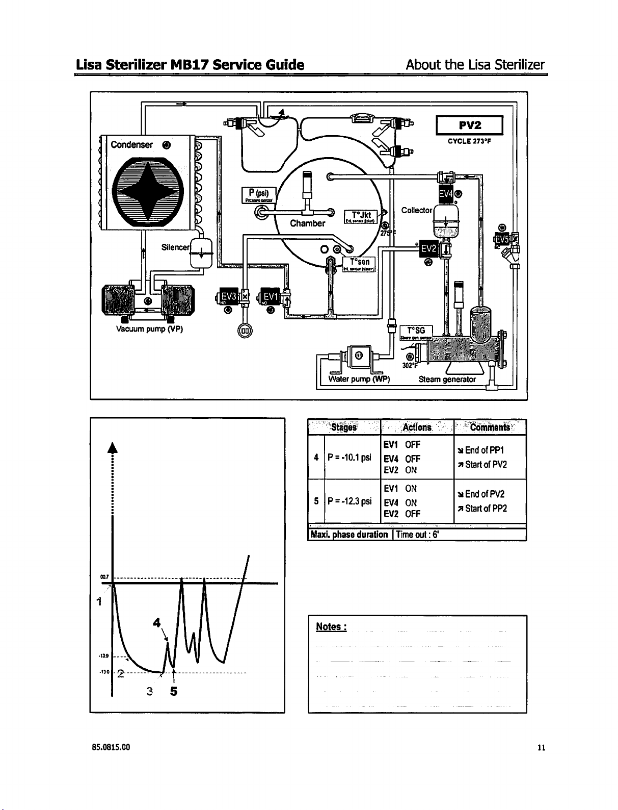
PV2
CYCLE
273°F
(WP)
Water
O
pump
|
À
60000.
à
|p=
40408 a ore
разра
Maxi,
phase
Actions | Comments
EV2
ON
va
ON
EV2
OFF
duration [ Time
out:
6
w
End
a
Start
w
End
A
Start
of
PP1
of
PV2
of
PV2
of
PP2
|
85.0815.00
il
Page 12
About
the
Lisa
Condenser
Sterilizer
"©
.
Lisa
Sterilizer
MB17
CYCLE
Service
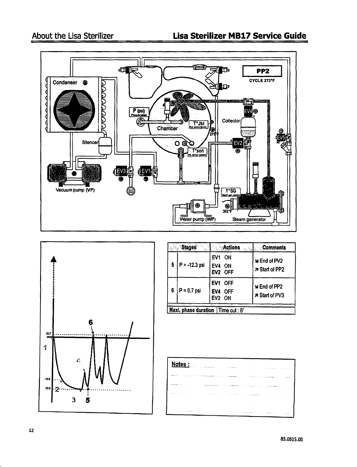
PP2
273°F
Guide
q
4
(
Vacuum
A
Silencer|
o
pump
(VP)
Pon Y "UA
|
Pa
==
p
‘Chamber
SEN
x
®
'
|!
T
ОЕ
ο
=
5
6
Мах,
^
A
T
IK
ter
.
Qu
i
Tsen
|
|
A
ehi
Water
pump
|P=-123psi
|P=07
psi
P
phase
duration
.
RU
TT
i
|
(WP)
EV1
|Ev4
EV2
EV1
EVA
Collector
=
©
T°SG
¡Sigan
sen
02°F
Steam
ON
ON
OFF
OFF
one
[Time
out
6
|
on
lo
s
generator
E
à
End
A
Start
à
End
A
Start
of
of
of
of
e
||
LI
1
PV2
PP2
PP2
PV3
12
Notes
:
85.0815.00
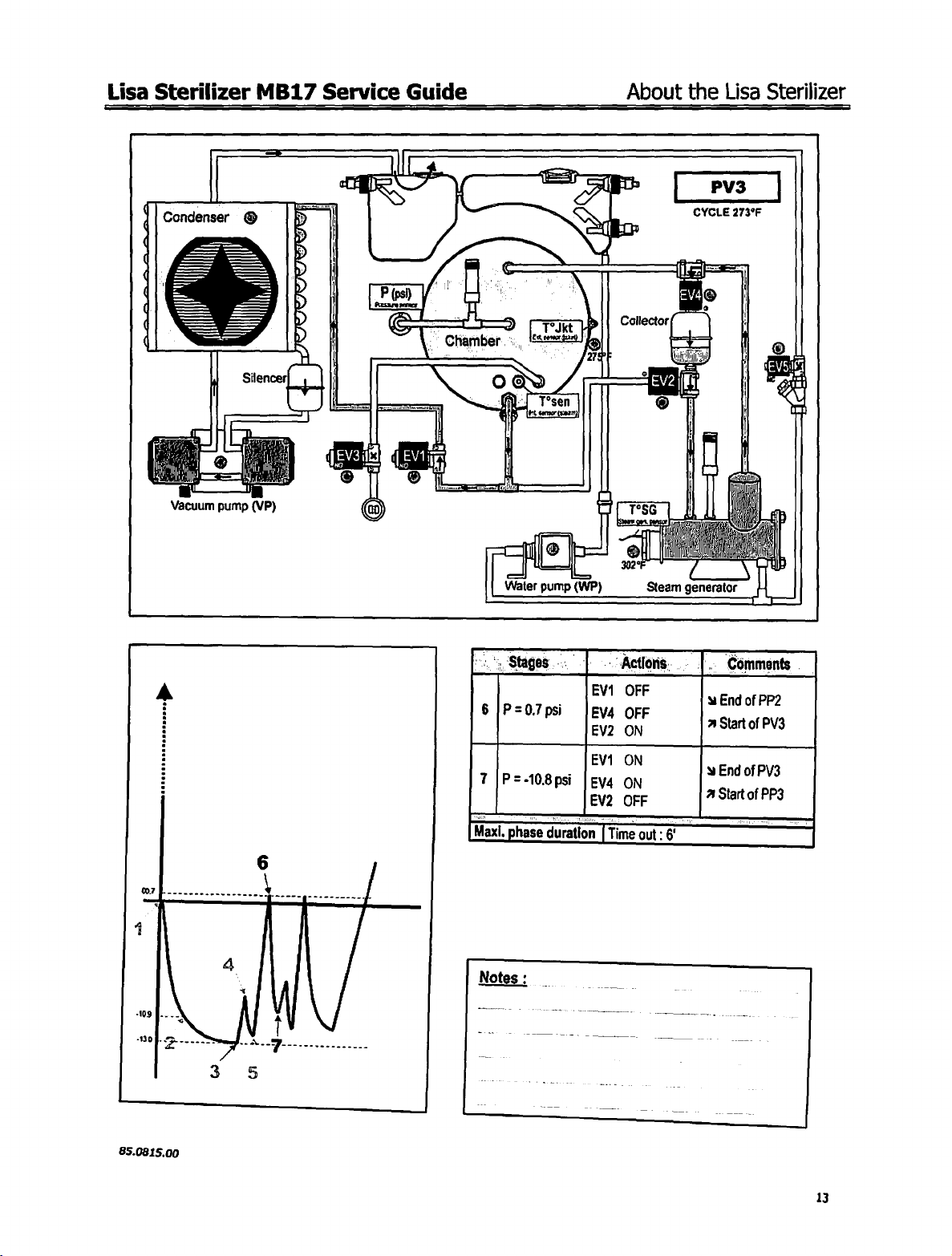
Page 13
Lisa
Sterilizer
MB17
Service
Guide
About
the
Lisa
Sterilizer
Condenser
(
(
q
;
q
.
|
Vacuum
©
pump
ーーーー
:
O
Silence
(VP)
|
y
<
|
|
|
lo
Ped
DO
lo.
há
© ©
(0
ROE
tl
/
7
Chanter
L
OG
è
ie
Water
cs,
Stages o İ
o
。
и
о
I
T°sen
ně
teror
tiež)
ep
pump
(WP)
A)
catador
2
TSG
302°F
Actions...)
©
iz
Steam
PV3
CYCLE
_
©
a
ES
[
i k
la
|
|
generator
273°F
|
|
|
|
Qu
|
|
|
|
=
Comments
=
7
.
À
:
:
85.0815.00
_
6
|P=0.7psi
Cars
7
了
|P=-108psi
Maxi,
phase
、
EV1
|EV4
EV2
EMT
|EV4
duration
T
OFF
OFF
ON
ON
ON
Time
out:
6
©
à
End
a
Start
y
End
of
PP2
of
PV3
of
PV3
13
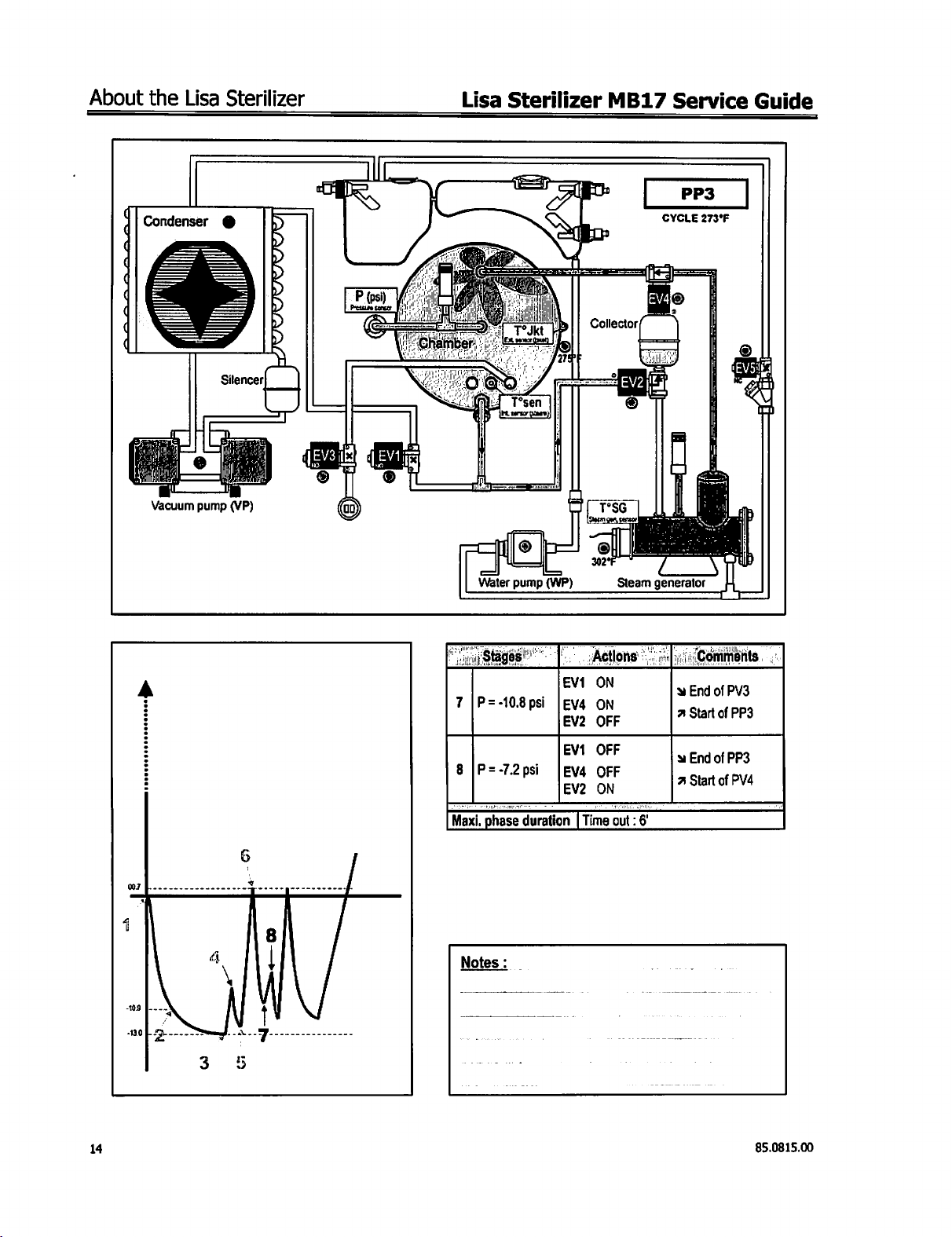
Page 14
About
the
Lisa
Sterilizer
Lisa
Sterilizer
MB17
Service
Guide
¿
(
(
(
|
di
Condenser
|
@
Water
pump
(WP)
Collector
©
1066
Saem
tensor
302
Steam
CYCLE
E)
2
generator
PP3
273°F
©
|
i
A
|
a
Maxi.
ss"
lost
İp-7204
<P
phase
|.
ep
Actions
ES
EV
İnn
Ev
duration | Time
OFF
OFF
ON
out:
6
|
End
of
2
Start
A
End
of
A
Start
PV3
of
PP3
PP3
of
PV4
14
85.0815.00
Page 15

Lisa
Sterilizer
MB17
Service
Guide
About
the
Lisa
Sterilizer
Condenser
|
®
|
dl:
dl
|.
Vacuum
pump
(VP)
S
a
il
Water
a
pump
(WP)
=
CYCLE
PV4
273°F
A
ee
a
[p=
2208 a Orr
9
|P=-11.6psi
Maxi,
phase
aa
EV2
ON
EV1
ON
|EV4
ON
EV2
OFF
duration
|
Time
out : 6"
3
EndofPP3
A
Start
of
PV4
à
End
of
PV4
A
Start
of
PP5
85.0815.00
15
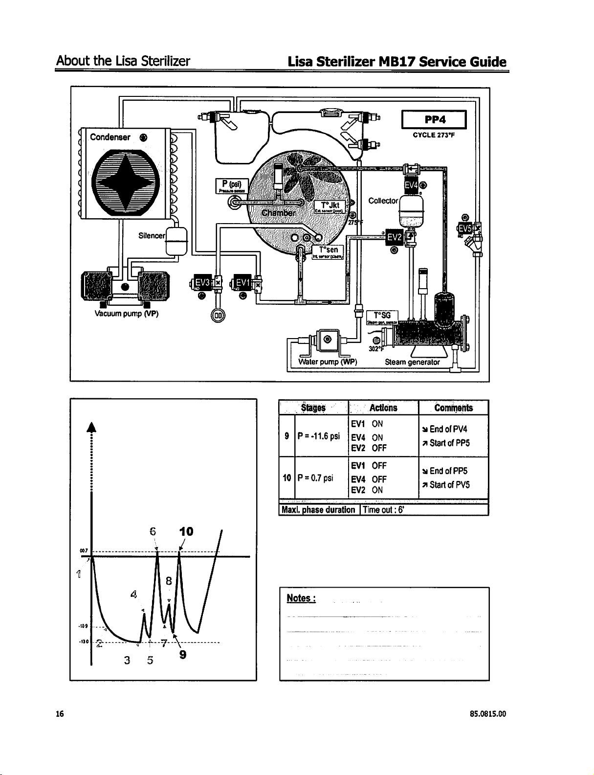
Page 16
About
the
Lisa
Sterilizer
Lisa
Sterilizer
MB17
Service
Guide
|
Condenser
или
и
OO
ジュ
Vacuum
pump
PP4
CYCLE
©
(VP)
Water
@
pump
|
(WP)
273°F
A
Stages
=
41.6
9
|P=-11.6psi E OFF
人
=
ad
Maxi,
phase
|"
Actions
EVI
Eva
ON
on
psi
ps
duration ] Time
out : 5
© _
Comments
y
End
a
Start
s
EndofPP5
a
Start
|
of
PV4
of
of
PPS
PVS
16
85.0815.00
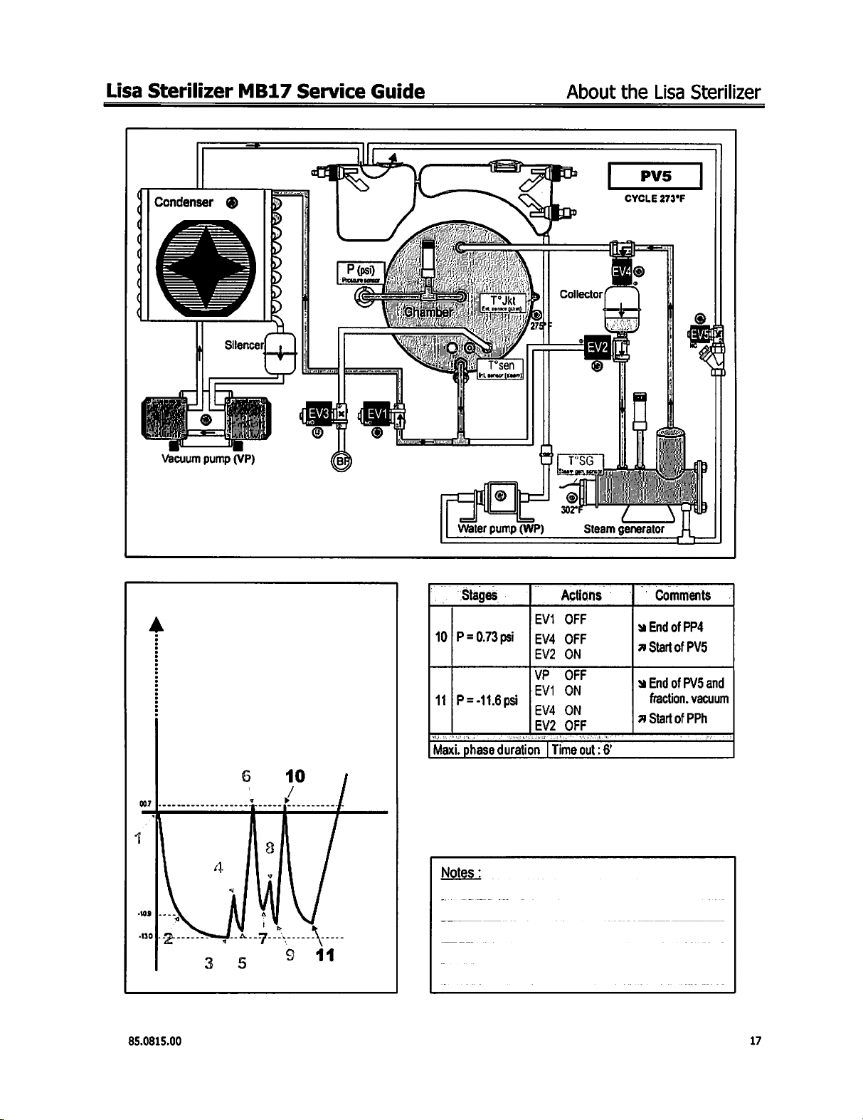
Page 17
Lisa
Sterilizer
MB17
Service
Guide
About
the
Lisa
Sterilizer
Condenser
Vacuum
pump
Y
(VP)
Water
©
pump
(WP)
ol
wd
Steam
CYCLE
le
(M
generator
PVS
273°F
NN
А
Stages
10|P=0.73psi
11 | P=-11.6
Maxi.
phase
-
psi
Actions
EV1
OFF
ΟΕΕ
|EV4
EV2
ON
E
EV4
ON
EV2
OFF
duration
|
Time
out
©
:6
Comments
©
|
End
Endo
v
a
Start
9
End
fraction,
Start
Start
of
of
of
of
of
PP4
ΡΝ5
PVS
and
vacuum
PPh
85.0815.00
17
Page 18

About
the
Lisa
Sterilizer
Lisa
Sterilizer
MB17
Service
Guide
A
ュー
うー
ュー
ュー
ュー
トー
ンー
Condenser
Vacuum
pump
@
(VP)
Water
ie
©
pump
|=
(WP)
Collector
SG
9
Steam
PPh
CYCLE
273°F
|
©
o
generator
A
275
232|
174|
他
人
"2
ÃO
11
Stages
11
|P = -11.6
P = 10.1
12
P=174psi
P=23.2
P = 27.5
13
|P
=31.3
Maxi.
phase
Notes:
-|
Actions
Ev 1 on
psi
EV2_OFF
psi
|EV4
OFF
for
15" | Coll.
psi
|EV2
ON
for
15" | discharged
psi
Steam
Generator | End
psi | poweredfregulated | 4
to
keep
P=31,3
duration
||
[20
min
psi | Holding
(4
Alarm
.
Comments
à
End
of
PV5
fraction.
7
Start
o
2CS
aclivated
condensation
steam
generator
of
PPh
Start
of
ATO
if
more)
and
vacuum
:
into
the
PR
time
|
18
85.0815.00
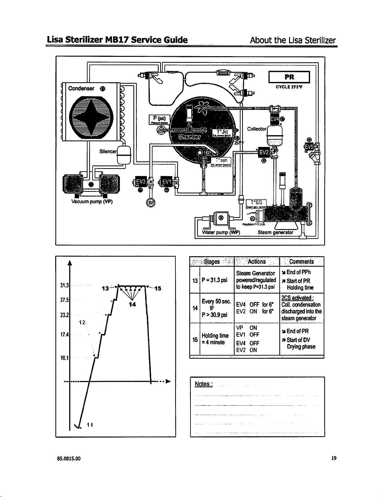
Page 19
Lisa
Sterilizer
MB17
Service
Guide
About
the
Lisa
Sterilizer
Condenser
Vacuum
pump
Y
(VP)
P
(psi)
18627“
©
Water
pump
i
(WP)
Collector
д
可 三 下 SG
su
ger,
gerer
Steam
CYCLE
generator
PR
"©
273°F
A
313|
275
23.2
17.4]:
ㆍ
101
“45
->
13|P=31.3psi
14
Every
90sec.
P
>
Holding
15
|
=
4
Notes
30.9
ime
minute
:
‘Actions
Steam
Generator
|
powered/regulated
to
keepP=31.3psi
|
EV4
OFF
.
[EV2
УР
|
EV1
EV4
EV2
ON
ON
OFF
OFF
ON
一
一
psi
一
-.
|:
|
|
|
2CS
tor6'
|
Coll.
for6”
|
discharged
steam
Comments
a
End
of
4
Start
of
Holding
activated
condensation
generator
send
of
a
Start
of
Drying
PPh
PR
time
into
PR
DV
phase
一
©
:
the
85.0815.00
19
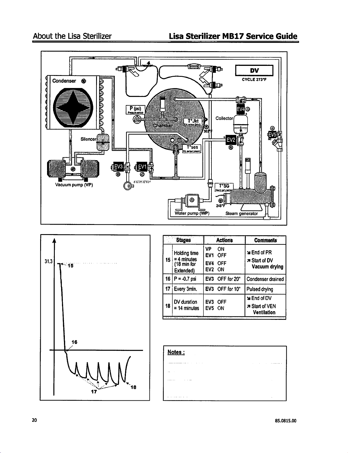
Page 20
About
the
Lisa
Sterilizer
Lisa
Sterilizer
MB17
Service
Guide
Condenser
q
q
(
(
(
q
q
Vacuum
]
pump
=
©
(VP)
Ď
o
>
=
x
|
=
DV
©
MM
Water
pump
|
(WP)
302°
Collector
=
[TSG
Bm
248°
Steam
©
MA
CYCLE
ID
3
i
T
| ;
li
i
3
generator
273°F
|
:
|
|
i
|
ioe
VÁM
|
=
4
313
TS
16
ン
q
BN
Sr
NA
Ne
17
+
ν
18
Stages
Holding
15 | =4
minutes
(18
min
Extended)
16|P=-0.7
17 | Every
DV
duration
18 | = 44
minutes | EV5
Notes
|
time | ey,
for
|
psi
3min.
圖
Actions
VP
N
OFF
EV4
OFF
|EV2
ON
|EV3
OFF
|EV3
OFF
|EV3
OFF
ON
for20"
|Condenser
for
10° | Pulsed
“Comments
à
End
of
PR
A
Start
of
DV
Vacuum
drying
©
End
of
DV
A
Start
of
VEN
Ventilation
drying
drained
20
85.0815.00
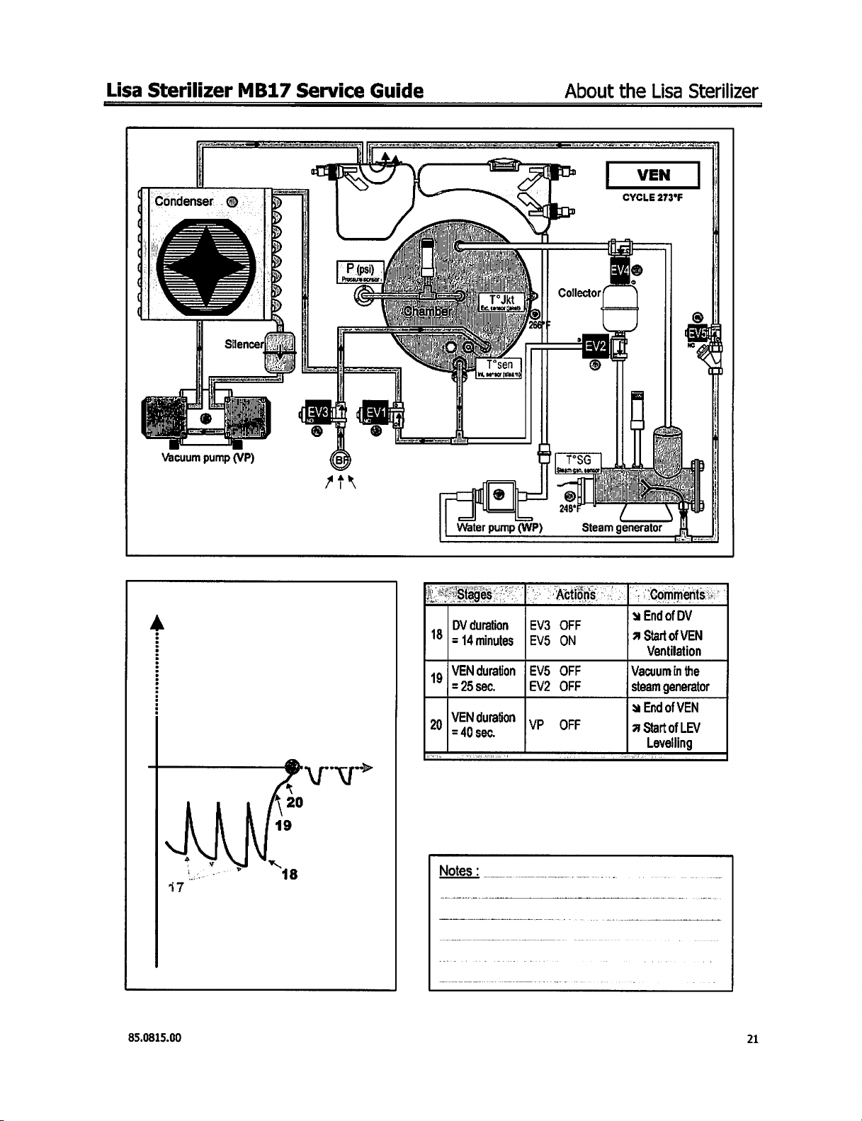
Page 21
Lisa
Sterilizer
고
|
Condenser
AE
Vacuum
pump
©-
(VP)
MB17
E
JE
Service
=
>
Y
Guide
=
>
T wa
-一
©
8
AIR
ral I ||
8
i
ИИ
|
=
Toe
|
isa
ir = i
ОНА n |
оаэ)
|
ala
Water
[ΙΙ
TI
T°sen
W
penser
pump
l
st
(staan
e
|
lp
ーー
(WP)
2
About
Collector
。
E
e
LT'SG
m
sul
©
248°
Steam
the
Lisa
See
VEN
CYCLE273F
$
Φ
|
и
RI т A Е
a i |
IM
Ret
generator
Sterilizer
7
{|
|
:
|
©
e
|
à
|
ИН
у |
|
т
|
|}
|
비
A
|
DV
duration
18 | =
44
minutes
19
VEN
duration | EVS
=
25
sec.
İline
=
40
sec.
M
Notes:
Oo...
,
=
Metións
|EV3
OFF
|EV5
ON
OFF
EV2
OFF
[YP
OF
—-
«| - Comments
wEnd
2
Start
Ventilation
Vacuum
steam
generator
à
End
|asmnougy
Levelling
of
DV
of
VEN
in
the
of
VEN
,
>”
85.0815.00
21
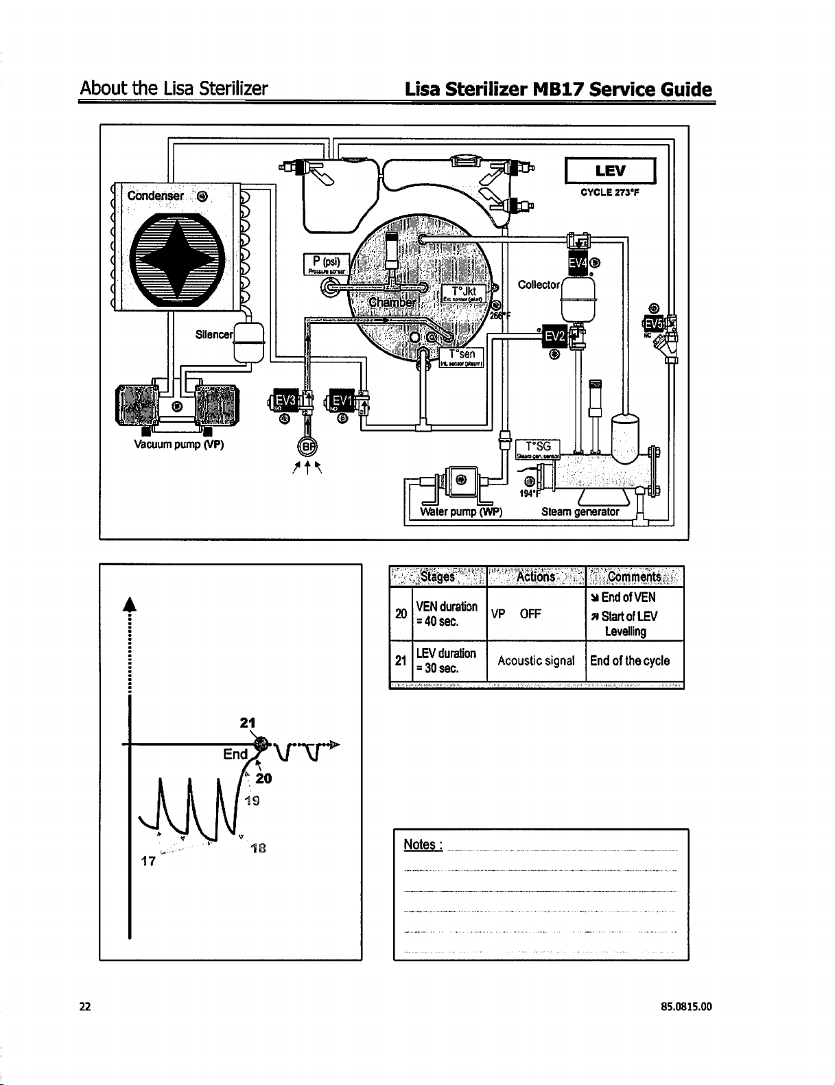
Page 22
About
the
Lisa
Sterilizer
Lisa
Sterilizer
MB17
Service
Guide
へ
‘Condenser
ュー
ヘー
T
Vacuum
©
pump
©
Silencerl
(VP)
LEV
CYCLE
9
273°F
4
+ +
17
나
18
|
OFF
VP
Acoustic
,
signal | End
duration
A
20
LEV
30
Notes
duration
sec.
:
21 | -
SEndofVEN
Start
a
Levelling
of
LEV
of
the
cycle
22
85.0815.00
Page 23
Lisa
Sterilizer
MB17
Service
Guide
Duration
About
the
Lisa
Sterilizer
5858
haa
\
\
te
3
&
IN
5
ei
Ng
$
人
=
5
Es
EE
8
2
2
ー
<
85.0815.00
LA
‧
N
Es
~
55
Gü
sk
dda
.
5
=
Bee.
585
5888
SEBE
tas
1638
|
Va
eg
BE
bal
23
Page 24
About
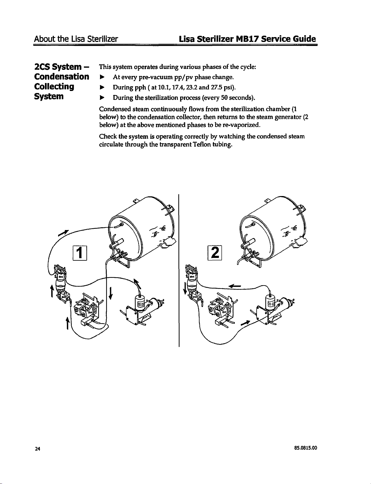
2CS
System
the
Lisa
Sterilizer
—
This
system
operates
during
Lisa
Sterilizer
various
phases
of
MB17
the
Service
cycle:
Guide
Condensation
Collecting
System
>
Atevery
>
During
b
During
Condensed
below)
below)
Check
circulate
to
the
at
the
the
through
pre-vacuum
pph
(at
10.1, 17.4,
the
sterilization
steam
continuously
condensation
above
system
mentioned
is
operating
the
pp/pv
phase
23.2
process
flows
collector,
phases
correctly
transparent
Teflon
change.
and
27.5
(every
from
then
to
by
tubing.
psi).
50
seconds).
the
sterilization
returns
be
watching
to
the
re-vaporized.
the
chamber
steam
generator
condensed
(1
(2
steam
24
85.0815.00
Page 25
Lisa
Sterilizer
Technical
Specifications
MB17
Power
Service
Requirements
Sterilizer:
-
Working
-
Storage
(empty)
-
Minimum
-
Nominal
-
Maximum
-
Maximum
-
Dimensions
-
Maximum
-
Clutter
of
-
Weight
-
Max.
mass
fully
loaded
-
Maximum
-
Maximum
Steam
generator:
-
Power/Voltage
-
Max.
pressure/
-
Safety
overpressure
Sterilization
-
Power/
-
Maximum
-
Safety
overpressure
-
Total
volume
-
Usable
space
-
Filter
Distilled
-
-
-
Connections
Miscellaneous
water
Water
quality
Min./Max.
(full
porous
Double
Guide
temperature/
temperature/
atmospheric
voltage
absorbed
current
overall
space
the
empty
in
heat
noise
chamber:
Voltage
pressure/
consumption
tank/
power
required
door
movement
working
output
level
Max.
valve
Max.
valve
(identical
(or
demineralized):
load)
Autonomy
Humidity
Humidity
pressure
condition
temperature
temperature
for
all
cycles)
phase
(0.5
About
230
VAC
bar)
16.1 / D:
410 / D:
Single
-
50/60Hz - 10A
50°-
104°F / 0-90%
10°-
40°C / 0-90%
-4°-
140°F / 0-90%
-20°-
60°C / 0-90%
7.25
psi
230
V
2100
W
9.2
A
W:
17.5 / H:
W:
445 / H:
W:19.1 / H:18.1 / D:
W:
485 / H:
W:
14.2 / H:
W:
360 / H:
106
Ib.
140N/foot
3000
<53
1700
58
psi/302°F
72.5
1000
34.8
36.3
17
liters
Dia.:
12.7
12
liters
0.3
um
Conform
7
to120z
Min 8 cycles
Parallel
Fully
touchscreen
Mains
Programmable
460 / D:
15.8 / D:
400 / D:
(49
kg)
(129.4
N/m?)
KJ/hr
dB
W/230
VAC
(4.0
bar/150°C)
psi (5.0
bar)
W/230
VAC
psi/280°F
psi
9.8
quarts
(2.5
bar)
(18
qt.)
in
(250
W:7.67/H:
W:
195/H:
to
the
(0.2
to
(full
printer
(24
mm)/Depth:
13060-1
0.35
porous
port
micro-processor
filter/2KV
over
stand-by
the
Lisa
+/-
10%
20.5
(in)
520
(mm)
224
(in)
570
(mm)
14.2
(in)
360
(mm)
bar/138°C)
13.8
in
8.07/
D:
11.81
205/
D:
300
(mm)
annex
E
liter)
load)
driven
and
controlled
tension
filter
mode
Sterilizer
(350
mm)
(in)
85.0815.00
25
Page 26
About
the
Lisa
Sterilizer
Technical
Specifications
(continued)
STERILIZER
93/42/EEC
PrEN
13060-1
work
PrEN
13060-2
EN
61010-1
EN
61010-2-041
sterilizer.
EN
50081-2
EN
50082-2
Chamber
Steam
generator
CLASS B conforms
Medical
(11/97)
tests.
(11/97)
(09/94)
(08/97)
(06/97)
(06/97)
Development
Development
Lisa
with
the
devices
Small
Small
Laboratory
Laboratory
Electromagnetic
Electromagnetic
and
and
Sterilizer
following
steam
sterilizer - General
steam
sterilizer - Particular
equipment - Safety
equipment - Specific
testing
conform
testing
conform
MB17
directives
compatibility - Emission.
compatibility - Immunity.
to
pressure
to
steam
and
Service
norms
:
requirements.
requirements
requirements.
instructions
vessel
regulations.
generator
regulations.
Guide
Type
and
for B type.
for
steam
26
85.0815.00
Page 27
Lisa
Sterilizer
MB17
Service
Guide
Maintenance
Section 2 —
User
Maintenance
Maintenance
Program
Maintenance
Note:
Frequency
Weekly
Every 3 months
Weekly
Every
*
*
Remove
year
Every 3 years
ΤΥ
ΟΥ
Refer
to
medical
the
mains
#
Cycles
50
400
50
1000
4000
device
cable
of
Operation
Clean
Clean
Clean
Replace
Clean
Replace
Service
technician.
regulations
before
the
the
the
the
the
the
by
y
for
examining
door
seal.
chamber,
external
surfaces.
filter.
main
water
door
seal.
an
approved
pp
your
country.
the
sterilizer.
trays
and
tank.
Spare
Number
-
rack.
-
54.0067.00
-
54.0014.00
-
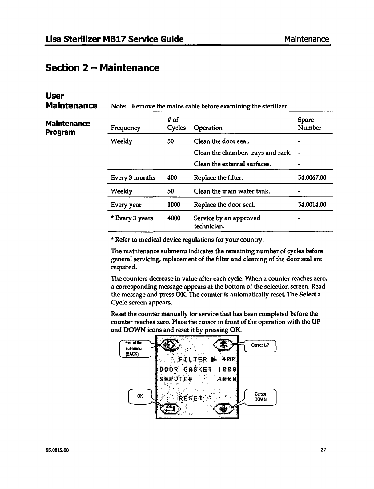
The
maintenance
general
servicing,
required.
The
counters decrease
a
corresponding
the
message
Cycle
Reset
the
counter
and
DOWN
Exit
submenu
and
screen
counter
reaches
icons
of
the
appears.
submenu
replacement
in
value
message
press
appears
OK.
manually
zero.
Place
and
reset
indicates
The
for
the
it
by
the
of
the
filter
after
each
at
the
counter
service
cursor
pressing
remaining
and
cleaning
cycle.
When a counter
bottom
is
that
in
front
of
automatically
has
been
of
the
OK.
number
of
the
the
selection
reset.
completed
operation
of
cycles
door
reaches
screen.
The
before
with
before
seal
are
zero,
Read
Select
a
the
the
UP
85.0815.00
27
Page 28
Maintenance
Cleaning
Door
Cleaning
Chamber,
and
Seal
Tray
the
the
Trays
Holder
Clean
with
alcohol.
The
porthole
1.
Remove
2.
Disconnect
3.
Clean
scouring
Rinse
4.
Clean
Note:
Ensure
>
Do
»
chamber.
»
Never
the
door
can
the
the
chamber
agent
with a damp
the
rack
that
not
bend
use
seal
and
the
also
be
cleaned
trays
from
and
remove
with a damp
if
necessary.
sponge
and
trays
using
you
clean
or
damage
disinfectants
Lisa
Sterilizer
porthole
the
the
all
around
the
to
with a lint
with a non-abrasive
chamber.
rack.
sponge
to
remove
the
same
temperature
clean
all
procedure.
the
sterilizer
the
chamber.
MB17
free
cloth
detergent.
moistened
traces
of
the
chamber.
sensor
at
Service
saturated
with a detergent
cleaning
the
bottom
Guide
or
agent.
of
the
Cleaning
External
Components
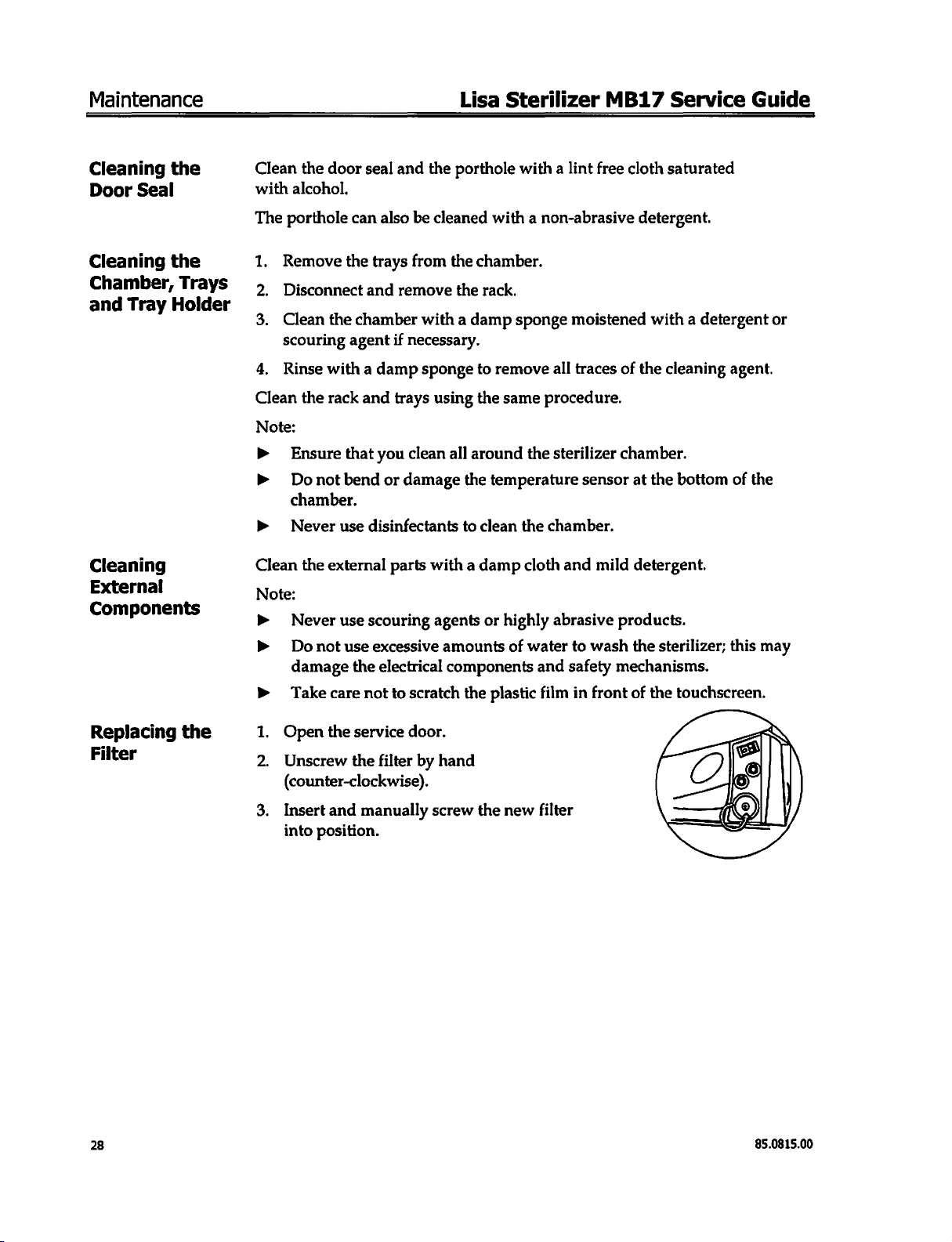
Replacing
Filter
the
Clean
the
external
Note:
>
Never
>
Do
damage
>
Take
1.
Open
Unscrew
(counter-clockwise).
Insert
into
use
not
care
the
and
position.
parts
scouring
use
excessive
the
electrical
not
service
the
filter
manually
to
with a damp
agents
amounts
components
scratch
door.
by
the
hand
screw
or
highly
of
plastic
the
new
cloth
abrasive
water
and
film
filter
and
mild
to
wash
safety
in
front
detergent.
products.
the
sterilizer;
mechanisms.
of
the
touchscreen.
this
may
28
85.0815.00
Page 29
Lisa
Sterilizer
MB17
Service
Guide
Maintenance
Cleaning
Main
Water
the
Tank
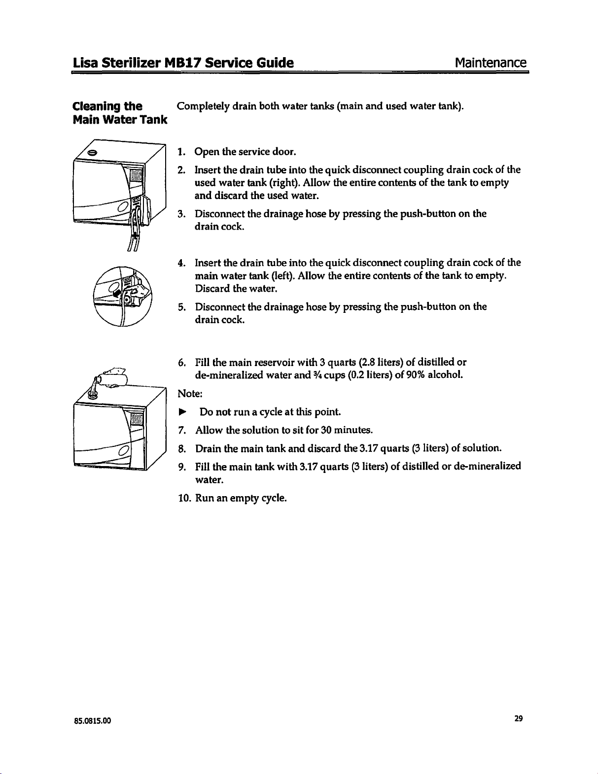
Completely
1.
Open
2.
Insert
used
and
3.
Disconnect
drain
4.
Insert
main
Discard
5.
Disconnect
drain
6.
Fill
de-mineralized
drain
the
the
water
discard
cock.
the
water
the
cock.
the
main
both
service
drain
drain
door.
tube
tank
(right).
the
used
the
drainage
tube
tank
(left).
water.
the
drainage
reservoir
water
water
tanks
into
the
quick
Allow
water.
hose
by
into
the
quick
Allow
with 3 quarts
and % cups
hose
the
by
(main
and
disconnect
the
entire
pressing
disconnect
entire
pressing
(2.8
(0.2
used
contents
the
push-button
contents
the
push-button
liters)
liters)
of
water
tank).
coupling
of
the
coupling
of
the
tank
of
distilled
90%
alcohol.
drain
tank
to
on
drain
to
on
or
cock
of
empty
the
cock
of
empty.
the
the
the
Note:
>
Do
not
7.
Allow
8.
Drain
9.
10.
Fill
water.
Run
the
the
the
an
main
runa
solution
main
tank
empty
cycle
at
to
tank
with
cycle.
this
sit
and
3.17
point.
for
30
minutes.
discard
quarts
the
(3
3.17
quarts
liters)
of
(3
liters)
distilled
or
of
solution.
de-mineralized
85.0815.00
29
Page 30
Maintenance
Replacing
Door
the
Seal
.
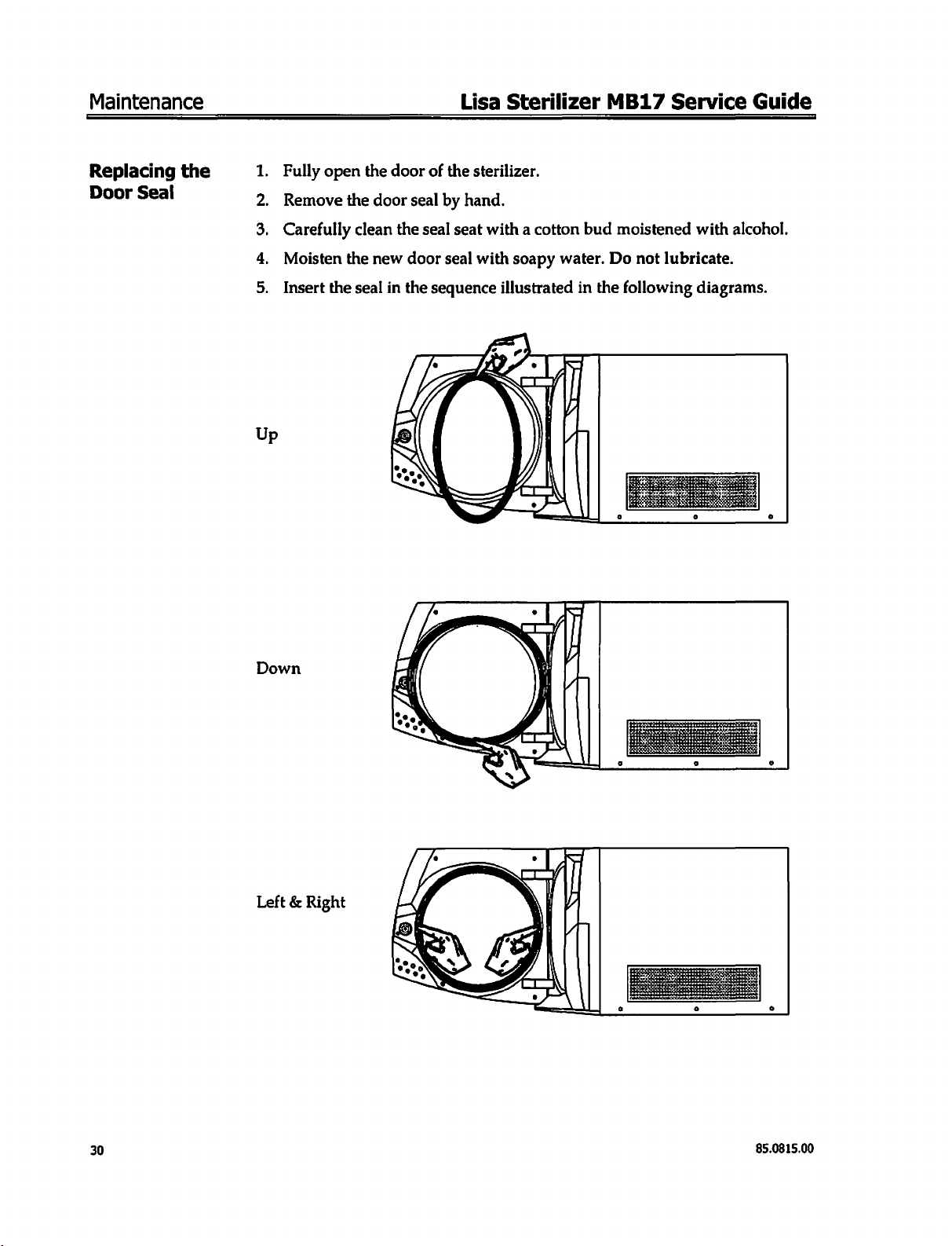
Fully
1
.
Remove
2
3.
Carefully
4.
Moisten
.
Insert
5
open
the
the
the
the
door
door
clean
new
seal
in
seal
the
door
the
seal
Lisa
of
the
sterilizer.
by
hand.
seat
with a cotton
seal
with
sequence
Sterilizer
bud
soapy
water.
illustrated
in
MB17
moistened
Do
not
the
following
Service
with
alcohol.
lubricate.
diagrams.
Guide
Down
Left & Right
30
85.0815.00
Page 31
Lisa
【 一 一 一 一
Sterilizer
一 一 一 一 一 一
MB17
Service
Guide
Maintenance
Service
Checklist
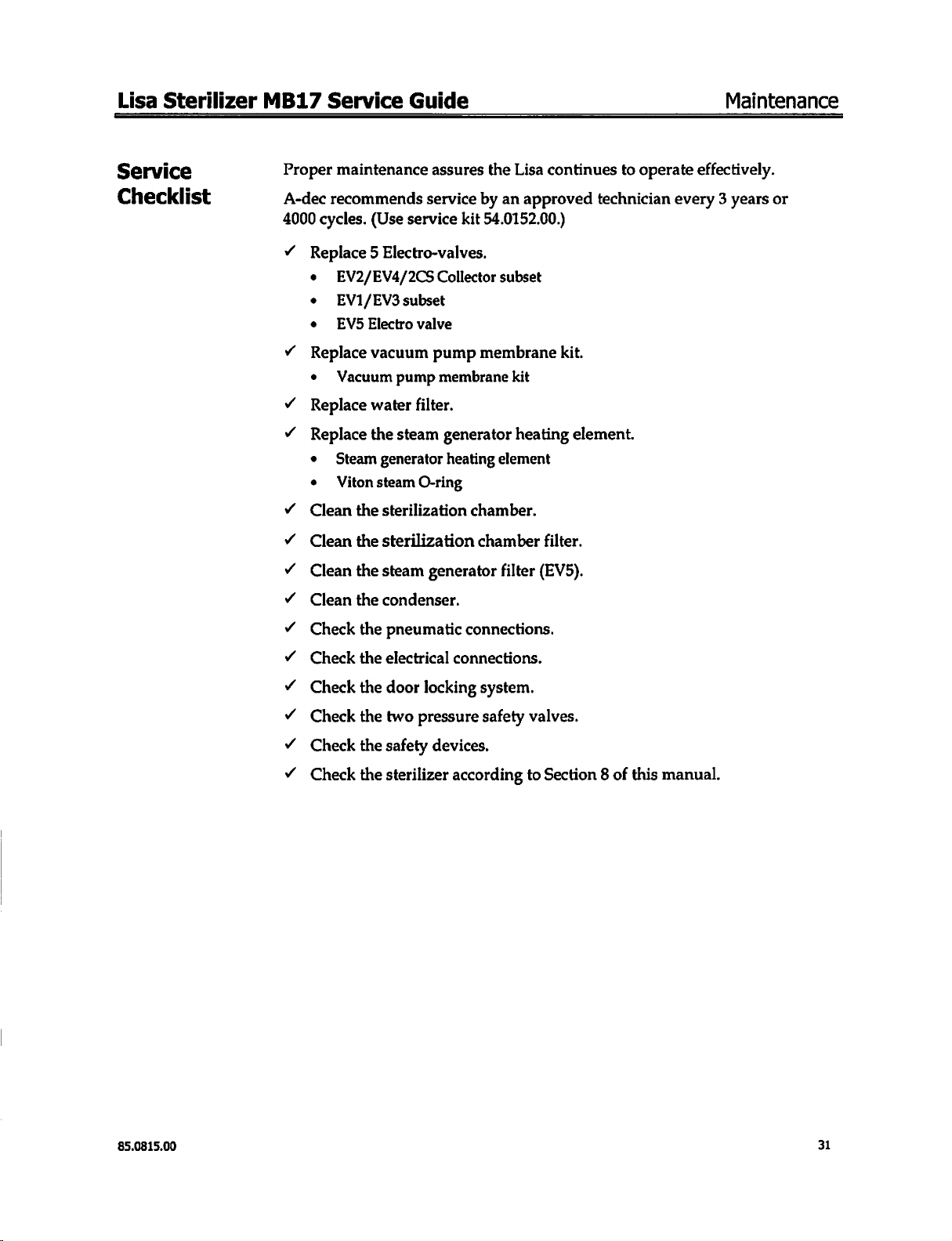
Proper
A-dec
4000
v
maintenance
recommends
cycles.
(Use
assures
service
service
Replace 5 Electro-valves.
e
EV2/EV4/2CS
e
EV1/EV3
e
V5
Replace
e
Vacuum
Replace
<
Replace
e
Steam
e
Viton
Clean
Clean
SOS
Clean
Clean
Electro
vacuum
water
the
generator
steam
the
sterilization
the
sterilization
the
steam
the
condenser.
Collector
subset
valve
pump
pump
membrane
filter.
steam
generator
heating
O-ring
generator
the
Lisa
by
an
approved
kit
54.0152.00.)
subset
membrane
kit
heating
element
chamber.
chamber
filter
continues
technician
kit.
element.
filter.
(EV5).
to
operate
effectively.
every 3 years
or
Check
Check
Check
Check
<
<
Check
<
Check
the
pneumatic
the
electrical
the
door
the
two
the
safety
the
sterilizer
connections.
connections.
locking
pressure
system.
safety
devices.
according
valves.
to
Section 8 of
this
manual.
85.0815.00
31
Page 32

Maintenance
Lisa
Sterilizer
MB17
Service
Guide
32
85.0815.00
Page 33

Lisa
Sterilizer
MB17
Service
Guide
Exploded
Views & Circuit
Diagrams
Section 3 —
Exploded
Views
Accessories
Exploded
Ref.
PartNumber
1
54.0019.00
2
54.0018.00
3
54.0029.00
4
54.0046.00
5
54.0024.00
6
54.0017.00
7
54.0188.00
Views & Circuit
Diagrams
Description
Anodized
Reversible
Drain
Mains
Funnel
Tray
Owner’s
perforated
rack
tubing
cable,
holder
Guide
67
In.
(170
aluminum
cm)
tray
85.0815.00
33
Page 34

Exploded
Views & Circuit
Diagrams
Lisa
Sterilizer
MB17
Service
Guide
External
(1 of
2)
Parts
Ref.
1
2
3
4
5
6
7
8
9
Part
Number
54.0127.00
54.0123.00
54.0138.00
54.0118.00
54.0251.00
54.0037.00
Description
Water
tank
cap
Water
tank / cover
Used
water
tank
Used
water
tank
Housing / cover
Composite
Screws : Pan
Rear
Chassis
washer
housing
foot
Head
plate
grommet
seal
cap
silencer
Phillips
M5 x 6
mm
34
85.0815.00
Page 35

Lisa
Sterilizer
MB17
Service
Guide
Exploded
Views & Circuit
Diagrams
External
(2 of
2)
Parts
Ref.
2
3
4
6
10
11
Part
1
54.0023.00
54.0014.00
54.0022.00
54.0021.00
5
54.0132.00
7
54.0253.00
8
54.0025.00
9
54.0121.00
54.0026.00
Number
Description
Composite
Door
Composite
Composite
Technical
Service
Touchscreen
Touchscreen
EMC
Screw
Composite
door
seal
fascia
technical
door
door
finger
fascia-Cover
pin
complete
external
(carter)
cover
door
sticker
protection
seal
85.0815.00
35
Page 36

Exploded
Views & Circuit
Diagrams
Lisa
Sterilizer
MB17
Service
Guide
Door
Complete
Ref.
20
21
22
23
24
25
26
27
28
29
30
31
1
2
3
4
5
6
7
8
9
10
11
12
13
14
15
16
17
18
19
Part
Number
54.0130.00
54.0033.00
54.0036.00
54.0034.00
54.0039.00
54.0005.00
54.0140.00
54.0006.00
54.0009.00
54.0010.00
Description
Door
complete
Lock
clip
Door
locking
Screw,
Washer
Door
arms
Door
locking
Teflon
Spacer
Lock
clip
Door
locking
Screw : Hex
Porthole
Nut
MS
Screw,
Wing
washer
Screw
Spacer
Screw,
Door
hinge
Washer,
Door
locking
Teflon
Lock
clip
Cast
aluminum
Fixed
Screw,
Friction
Rotating
Spacer
Porthole
arm
button
5.3
ID x 20
actuator
pin
guide
washer,
pin
socket
spring
button
M4 x 5mm
washer
hex
socket
mount
5.3
mm
arm
guide
D16
D16
eccentric
button
disc
1mm
door
disc
0.5mm
subset
head
hex
mm
20
mm
seal
cap
head
hex
DS
cap
(door
ID x 15
spring
door
porthole
head
hex
locking
socket
OD
IO x 28
m3 x 10
socket
M8 x 50
side)
mm
disc
socket
disc
MS x 10
mm
mm
m5 x 20
mm
OD
M4 x 6
mm
OD x 0.5
mm
mm
mm
thk
36
85.0815.00
Page 37

Lisa
Sterilizer
MB17
Service
Guide
LR
SUA
Sİ
eA
Exploded
Views & C
ircuit
Diagrams
85.0815.00
37
Page 38

Exploded
Views & Circuit
Diagrams
Lisa
Sterilizer
MB17
Service
Guide
Water
Facade
Tank
/
Ref.
3
4
5
6
7
8
9
10
11
12
13
14
15
16
17
18
19
20
21
PartNumber
1
2
54.0020.00
54.0047.00
54.0145.00
54.0008.00
54.0139.00
54.0064.00
54.0063.00
54.0067.00
Description
Water
tank
complete
Water
tank
only
Water
level
sensor
Water
level
sensor
Pipe
seal
cap
Door
hinge
(chamber
Door
hinge
0.5mm
M10
flat
washer
M10
split
lock
Screw,
Screw,
M6
6
Base
Maln
EMC
Drain
Drain
Filter
Screw
Nut
hex
hex
split
lock
mm
ID
frame
switch
filter 9 pin
fitting,
fitting,
M3.5 x 9.55
MS
socket
socket
washer
flat
washer
(circuit
female
female
seal
spacer
washer
cap
cap
breaker)
(NM
(NM
mm
side)
screw
screw
blue)
grey)
M10 x 20
M6 x 16mm
mm
38
85.0815.00
Page 39

Lisa
Sterilizer
MB17
Service
Guide
Exploded
Views & Circuit
Diagrams
Right
Side
Ref.
10
11
PartNumber
1
54.0150.00
2
54.0031.00
3
4
54.0050.00
5
6
54.0036.00
7
8
54.0053.00
9
54.0051.00
54.0052.00
54.0249.00
Description
Vacuum
CPU
CPU
Vacuum
Internal
Screw,
Screw,
Vacuum
Vacuum
(4x
Vacuum
Clip,
pump
silencer
board
board
metal
pump
lock
washer, 5 mm
button
head
button
head
pump
head
pump
membrane
valve + O-ring + 2x
pump
diaphragm
vacuum
pump
carrier
hex
socket
hex
socket
(1
pce)
diaphragm)
valve
kit
(1
MS x 10
M4
pce)
x 6
mm
mm
85.0815.00
39
Page 40

Exploded
Left
Side
Views & Circuit
Ref.
1
2
3
4
5
6
7
8
9
10
11
12
13
14
15
16
17
18
19
20
21
22
Diagrams
PartNumber
54.0092.00
54.0070.00
54.0007.00
54.0011.00
54.0054.00
54.0137.00
54.0038.00
54.0149.00
54.0049.00
54.0054.00
54.0012.00
54.0066.01
Lisa
Sterilizer
Description
Steam
generator
Steam
generator
Viton
O-ring
Heating
Fixing
Thermal
element
clip
overload
PT100 D 6x120
Water
pump
Water
pump
Fitting
Spacer 8 mm x 3.2
One-way
Water
PT100
Chamber
Water
Nut
valve
pump
6x40
thermal-overload
filter
Washer
Grower
washer
Nut
Grower
washer
Washer
complete
only
subset
rubber
complete
Class B outside
MB17
support
mm x 1.5
chamber
mm
Service
Guide
40
85.0815.00
Page 41

Lisa
—
Rear
(1
of
Sterilizer
MB17
Side
2)
Ref.
1
mn
[uu
Dun
BIN
Service
Guide
PartNumber
54.0045.00
54.0128.00
54.0015.00
Exploded
Description
Condenser
Condenser
Condenser
Mains
Screw
Washer
Screw
Nylon
subset
fan
filter
box
nipple
230Vac
complete
Views & Circuit
with
transformer
Diagrams
NN
SE _ à
η
RNN
M
κ.
Μι
na]
SAN
a
TS
这
NNN R È
QE
mE M nl
ii x i
a
i
내비
i
NN
SH
o
|]
{
Ч
|
AS
S
NE
s
n
IN
則
85.0815.00
41
Page 42

Exploded
Rear
(2
of
Views & Circuit
Side
2)
Ref.
1
2
3b
4
5
6
7
Diagrams
PartNumber
54.0027.00
54.0028.00
54.0090.00
54.0066.01
54.0055.00
54.0141.00
54.0015.00
0
FI
a
LAI
IS
75
M
ET
È
x
©
at)
ATE
Lisa
Sterilizer
Description
EV2 / EV4 / 2CS
EV1 / EV3
EVS / Filter
Water
filter
PT100
5x100
Chamber
Bi-cone
Teflon
subset
subset
subset
Class A internal
outlet
filter
seal
MB17
Service
Guide
42
85.0815.00
Page 43

Lisa
Sterilizer
Top
Side
MB17
Ref.
1
2
3
4
5
6
7
8
9
10
Service
PartNumber
54,0129.00
54.0062.00
54.0061.00
54.0011.00
Guide
Description
EMC
Printer
Pressure
Safety
Screw
Washer
Pressure
Pressure
Safety
Steam
Exploded
filter
9-pin
flat
cable
safety
valve
manifold
safety
safety
valves
housing
generator
Views & Circuit
EMC
ferrite
valves
subset
valve 5 bar
valve
2.4
bar
thermal-overload
Diagrams
85.0815.00
43
Page 44
Exploded
Views & Circuit
Diagrams
Lisa
Sterilizer
MB17
Service
Guide
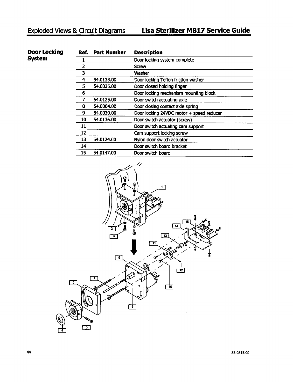
Door
System
Locking
Ref.
10
11
12
13
14
15
PartNumber
1
2
3
4
54.0133.00
5
54.0035.00
6
7
54.0125.00
8
54.0004.00
9
54.0030.00
54.0136.00
54.0124.00
54.0147.00
Description
Door
locking
Screw
Washer
Door
Door
closed
Door
locking
Door
switch
Door
closing
Door
Door
switch
Door
switch
Cam
support
Nylon
Door
switch
Door
switch
locking
locking
door
system
Teflon
holding
mechanism
actuating
contact
24VDC
actuator
actuating
locking
switch
board
board
complete
friction
finger
actuator
bracket
washer
mounting
axle
axle
spring
motor + speed
(screw)
cam
support
screw
block
reducer
85.0815.00
Page 45

Lisa
Sterilizer
MB17
Service
Guide
Exploded
Views & Circuit
Diagrams
EV2/EV4/2CS
Collector
(54.0027.00)
Subset
Ref,
1°
alalalejm
Part
Number
54.0126.00
Description
2CS
collector
3
way
3
way
Fitting
Fitting
Fitting
15cc
valve
1/4x2.3
valve
coil
1/4 - 1/8
90°
M1/4
90°
F1/8 T 6/4
T6/4
24VCC
(EV2-EV4)
85.0815.00
45
Page 46

Exploded
Views & Circuit
Diagrams
Lisa
Sterilizer
MB17
Service
Guide
EV1/EV3
(54.0028.00)
Subset
Ref,
bd
ом
A
uloví
[oo
O
Part
Number
54.0250.00
54.0153.00
Description
EV1-EV3
2
way
Solenoid,
Fitting
Fitting
Fitting
(EV1)
Nyton
Fitting
metal
valve
12 volt
90°
M1/4
90°
M1/4
M1/4
3-way
clip
M1/4
NO
T6/4
manifold
T6/4
bracket
1/4x4.5
D7
T6/4
24VCC
(EV1-EV3)
46
85.0815.00
Page 47

Lisa
Sterilizer
EV5/
Filter
Subset
(54.0090.00)
MB17
Ref.
1
jm
jo
jua
Service
Part
Number
54.0141.00
Guide
Exploded
Description
Brass
filter
complete
2
way
valve
NC
Filter
only
(EVS / chamber)
Fitting
M1/8
T6/4
Fitting
M1/8
M1/4
Fitting
M1/8
D7
Views & Circuit
(EV5
/
chamber)
1/8x2
24VCC
(EV5)
Diagrams
85.0815.00
47
Page 48

Exploded
CPU
Board
Fuses
Views & Circuit
Ref.
1
2
3
4
5
Diagrams
PartNumber
54.0040.00
54.0042.00
54.0042.00
54.0041.00
54.0043.00
Lisa
Sterilizer
Description
F1
(230V) : fuse
F2
(9V) : fuse の 5x20
F3
(11V) : fuse の 5x20
F4
(-15V):
F5
(24V):
Door
fuse の 5x20
fuse の 5x20
motor
95x20
2AT
2AT
1AT
6.3AT
MB17
3.15AT
250V — Mains
250V - PT100 - MPX-Analog
250V - 5V-Digital
250V - Touchscreen-analod
250V - Electro-valves
Service
230V
-
Guide
(+)
(-)
[3]
[2]
48
85.0815.00
Page 49

Lisa
Diagrams
Electrical
Sterilizer
Circuit
MB17
Diagram
Service
Rat
Guide
Exploded
QD
©,
Y
に
JL
向
ak
ofre
Views & Circuit
|
때
Diagrams
rs:
学
96
OS
:
E)
;
;
PRESSURI
>EENSOR
e
i
e
MAS
a
ra
BELEK:
AA
a
wr]
Ga
=
°
te
8
28
DE
si
Si
z
こ
AR
85.0815.00
LEGEND
COLOUR
49
Page 50

Exploded
Views & Circuit
Diagrams
Lisa
Sterilizer
MB17
Service
Guide
Hydraulic
Circuit
Diagram
(1
of
2)
50
85.0815.00
Page 51

Lisa
Sterilizer
MB17
Service
Guide
Exploded
Views
& Circuit
Diagrams
Hydraulic
Circuit
Diagram
(2
of
2)
Rear
85.0815.00
51
Page 52

Exploded
Views & Circuit
Diagrams
Lisa
Sterilizer
MB17
Service
Guide
52
85.0815.00
Page 53

Lisa
Sterilizer
MB17
Service
Guide
Testing
Prior
to
Repair
Section 4 —
Vacuum
Test
Testing
Use
this
>
The
>
The
The
profile
>
A
vacuum
>
A
stabilization
> A
testing
Pressure
Prior
test
efficiency
tightness
of
to
to
validate
the
cycle
phase
period
(psi)
of
Repair
the
of
the
vacuum
the
pneumatic
specific
up
to
period
of
16’
performance
pump.
circuit.
to
this
test
P1 = -
12.3
psi.
of
5’
=>
T2.
=>
T'3.
Reading
of
the
sterilizer
includes:
Reading
of
P3.
Duration
T3
of
P2.
in
terms
of
leakage:
SERVICE
85.0815.00
BY.
Select
for
16
Important:
(0.013
0.19
psi/
BURCUYUM
and
start
the
minutes,
bar/
then
According
min)
or
min
(0.013
TEST
DIAGNOSTICO
Vacuum
display a “pass”
greater
bar/
Test
in
the
or
PrEN13060
is
min)
norm, a vacuum
unacceptable. A measurable
will
give a “fail”
un
SERVICE
“fail”
message.
submenu.
leak
message.
of
leak
The
0.19
of
test
psi/
min
I
will
run
53
Page 54

Testing
Bowie
Test
b
È
Pressure
ni
(psi)
oğlu
Prior
&
Dick
to
Repair
The
Bowie & Dick
porous
small
indicator
equipment
type
packet
strip
on
Test
(also
load.
It
comprises
in
the
middle
(physic-chemical
performance
om
四
in
>
b
The
cycles
> a temperature
>
»
> a drying
Lisa
Sterilizer
called
Brown
several
of
which
test).
terms
of
Pre-vacuum
penetration.
Temperature
saturated
cycle
profile
with:
apressureof
asterilization
guaranteeing a security
false
results.
Test)
sheets
there
is a chemical
This
test
textile
load
efficiency
and
steam
is
identical
of
31.3
plateau
time
of 4 min
is
of
paper
is
used
sterilization,
pressure
during
275.9°F
psi.
MB17
representative
and
of 3 min
to
Service
and
foam
heat-sensitive
to
validate
i.e.:
thus
steam
parameters
the
holding
to
that
of
other
(135.5°C).
20
sec
margin.
prevent
Guide
of
the
small
wrapped
the
of
the
time.
ina
To
run
Place
the
chamber,
Select
Note:
Once
the
Caution:
Remove
m
the
test:
Bowie & Dick
with
and
start
the
You
can
number,
cycle
is
the
the
indicator
DBED/HELIX
Test
the
label
B&D
cycle
enter
your
on
each
completed,
packet
VACUUM
will
strip
from
(complete
facing
upwards.
from
the
name,
test
open
be
for
filing
the
very
the
center
the
door
hot.
TEST
TEST
0000
packet)
SERVICE
on
date,
cycle
purposes.
and
of
the
>
the
lower
submenu.
number
remove
packet.
CVCLE
回
|
the
tray
of
and
sterilizer
test.
BED
the
JEST
85.0815.00
Page 55

Lisa
Sterilizer
MB17
Service
Guide
Testing
Prior
to
Repair
The
The
result
excessive
Correct
radial
turned
is
also
temperature).
result:
strips
black.
incorrect,
have
if
the
indicator
is
The
same
gray
Incorrect
central
or
part
color
as
silver
(over-exposure,
result:
is
not
the
edges.
the
i.e.
85.0815.00
55
Page 56

Testing
Prior
to
Repair
Lisa
Sterilizer
MB17
Service
Guide
Accessing
Diagnostic
Screens
the
The
DIAGNOSTIC
sterilizer
troubleshooting.
To
1.
without running a complete
access
Inthe
your
the
DIAGNOSTIC
SERVICE
selection.
B&D / HELIX
VACUUM
DIAGNOSTIC
=
2.
Consecutively
menu
submenu,
press
allows
TEST
1,
you
to
cycle.
menu:
select
DIAGNOSTIC.
TEST
2, 3 and 4 icons.
check
This
The
every
is
useful
first
single
component
during
Press
test
screen
OK
to
confirm
displays.
of
the
56
DIAGNOSTIC
NTER
CODE
85.0815.00
Page 57

Lisa
Sterilizer
Screens
d
and
2
1
MB17
Use
1.
2.
3.
Service
screens 1 and 2 to
Select
the
powered
Select a second
press
OK.
On
screen
to
screen
Guide
item
to
for 8 seconds
item
If
you
2,
select
3,
select
select
be
tested
to
want
the
NEXT
and
and
and
released.
be
tested
to
exit
item
to
and
test
all
press
or
the
test
be
tested
press
Testing
components.
OK.
The
select
NEXT
screens,
OK.
and
press
press
Prior
component
to
go
to
screen 2 and
BACK.
OK.
If
you
to
will
want
Repair
be
to
go
Screen
3
Use
screen 3 to
Select
PRESSURE
press
Select
the
Press
BACK
select
unit
Screen
EVI
EV2
EV3
EVA
EVS
EVO
VACUUM
NEXT
set
OK.
desired
to
go
NEXT
PRESSURE
TEMPERAT.
PUMP
the
UNIT
to
previous
to
go
UNIT
UNIT
1
©
pressure
or
and
to
and
TEMPERATURE
press
screen,
screen 4 and
(8)
temperature
OK.
select a second
press
№
MBAR
ОКРА
gesi
units.
UNIT
OK.
Screen
WATER
PUMP
WATER
PUMP
GENERAT.
CHAMBER
DOOR
DOOR
CONDENSER
>
NEXT___
to
be
parameter
HEATER
HEATER
LOCKING
OPENING
set
and
A
2
1
2
FAN
LY
to
set,
or
85.0815.00
NEXT...
2
57
Page 58

Testing
Prior
to
Repair
Press
previous
Use
»
^
UP
P
OK
screen.
or
DOWN
BCELSIUS
O
FAHARENHEIT
to
confirm
Lisa
to
select
<b>
(9)
your
selection,
Sterilizer
the
temperature
|
or
press
MB17
unit.
BACK
Service
to
return
to
the
Guide
58
85.0815.00
Page 59

Lisa
Sterilizer
Accessing
Screen
4
MB17
The
the
shown
Service
hardware
hardware
below.
Guide
key
is
safety
key
required
to
the
to
modify
serial
functions
port
located
Testing
on
the
4th
behind
the
Prior
to
screen.
service
Repair
Connect
door,
as
Loop
Cycles
Function
Use
the
tanks
»
Select
tested.
Loop
must
be
LOOP
Use a manual
(2
Cycles
function
connected
CYCLES
©
&
LOOP
CYCLES
LOOP
LIMITED
CLEAR
COUNTER
ACTIVE
CYCLE
GAS / TEST
WATER
SUPPLY
HARDWARE
to
run
together
from
stop
to
screen 4 and
to
interrupt
©
22
KEY
unlimited
recycle
the
press
the
consecutive
water.
OK
test.
cycles.
to
run
the
Both
water
cycle
to
be
Loop
Select
Function
85.0815.00
Use
the
cycles.
1.
2.
Both
Select
Set
LOOP
water
LOOP
SELECT
tanks
SELECT
© ®
LOOP
CYCLE
LOOP
SELECT
CLEAR
COUNTER
ACTIVE
CYCLE
GAS / TEST
REV.
OSMOSIS
of
+
^
the
{>
number
function
must
be
from
くめ
cycles
to
to
run a limited
connected
screen 4 and
|
be
run.
number
together
press
to
OK.
of
consecutive
recycle
the
water.
59
Page 60

Testing
Prior
to
Repair
Lisa
=
Sterilizer
MB17
Service
Guide
Clear
Function
Counter
3.
Use
1.
QUANTITY
0002
&
SELECT
Use
the
side
arrow
icon
change
Press
Run
the
Select
the
OK
the
cycle
Clear
CLEAR
(>
number
and
return
to
be
Counter
COUNTER
LOOP
CYCLE
LOOP
SELECT
CLEAR
COUNTER
ACTIVE
CYCLE
GAS / TEST
REV.
OSMOSIS
by
to
tested.
function
くめ
using
to
move
the
the
previous
Use a manual
to
reset
from
screen 4 and
>
the
cursor
arrow
screen.
the
under
keys.
stop
cycle
press
the
to
interrupt
counter.
OK.
desired
the
test.
digit
and
2.
^
Press
and
return
BACK
to
to
the
CLEAR
quit
without
previous
COUNTER
くめ
resetting
screen.
(he
counter.
Press
OK
to
reset
(he
counter
85.0815.00
Page 61

Lisa
Sterilizer
MB17
Service
Guide
Testing
Prior
to
Repair
Active
Function
Cycle
Use
1.
2.
3.
the
ACTIVE
Select
CYCLE
ACTIVE
LOOP
LOOP
CLEAR
B>
ACTIVE
GAS / TEST
REV.
>
On
the
resulting
and
disabled
(P
MB-STAND.
O
B-EXTEND
(C
B-STAND. | 250
>
To
modify a status,
to
go
to
the
previous
function
CYCLE
CYCLE
SELECT
COUNTER
CYCLE
OSMOSIS
Di
screen,
cycles,
respectively.
select
screen.
to
from
screen 4 and
B
the
black
>
273
273
©
the
desired
enable
and
and
white
cycle
disable
press
OK.
squares
then
press
cycles.
show
the
OK.
Press
enabled
BACK
Gas/Test
Function
Rev.
Function
85.0815.00
Osmosis
Use
the
the
PR
to
the
»
Select
ον
Use
the
GAS/TEST
phase,
condensed
to
GAS
LOOP
LOOP
CLEAR
ACTIVE
D>
GAS / TEST
REV.
REV.
OSMOSIS
function
evaluate
steam
volume
TEST
from
CYCLE
SELECT
COUNTER
CYCLE
OSMOSIS
function
to
download
the
proportion
(<3.5%).
screen 4 and
LD,
©
to
the
of
non-condensable
press
configure
chamber
OK.
the
external
steam
water
content
gases
respective
supply.
during
61
Page 62

Testing
Prior
to
Repair
Lisa
Sterilizer
MB17
Service
Guide
62
85.0815.00
Page 63
Lisa
Sterilizer
MB17
Service
Guide
Troubleshooting
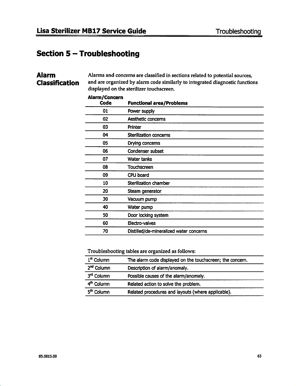
Section 5 —
Alarm
Classification
Troubleshooting
Alarms
and
displayed
Alarm/Concern
and
are
organized
on
Code
01
02
03
04
05
06
07
08
09
10
20
30
40
50
60
70
concerns
by
the
sterilizer
Functional
Power
Aesthetic
Printer
Sterilization
Drying
Condenser
Water
Touchscreen
CPU
Sterilization
Steam
Vacuum
Water
Door
Electro-valves
Distilled/de-mineralized
are
classified
alarm
code
touchscreen.
area/Problems
supply
concerns
concerns
concerns
subset
tanks
board
chamber
generator
pump
pump
locking
system
in
sections
similarly
to
water
related
integrated
to
potential
diagnostic
concerns
sources,
functions
85.0815.00
Troubleshooting
1%
Column
2™
Column
3
Column
4"
Column
5"
Column
tables
are
organized
The
alarm
Description
Possible
Related
Related
causes
action
procedures
as
code
displayed
of
alarm/anomaly.
of
the
alarm/anomaly.
to
solve
the
and
follows:
on the
touchscreen;
problem.
layouts
(where
the
concern.
applicable).
63
Page 64

Troubleshooting
©
DESCRIPTION
CODE
Power
AOL
230°
A10
|
А11
|
А12
A13
A14
CHAMBER
A15
T°
T°
A16
T°
A17
|
A18
A21
|
ATOR_
A22
STEAM
|
GE
A23
A31
A32
VACUUM
A33
|
A34
A52
DOOR
|
A63
VALVES
failure
If
duration
T°
chamber
T°
chamber
T°
theoretical > 278.6°F
T°
theoretical > 137°C
T°
theoretical < 273.2°F
T°
theoretical > 134°C
T°
sen < 273.2°F/249.8°F
sen < 101°C/121°C
sen > 278.6°F/255.2°F
sen > 137°C/124°C
External
Internal
Steam
Steam
Steam
3
minutes
Pressure > -2.9
4
minutes
Pressure > -7.2
The
<-11.6
The
vacuum
Door
DOOR
2
minutes
Pressure < -10.1
of
heater > Set + 72°F
heater < Set - 72°F
chamber
chamber
generator
generator
generator
after
after
value
of
psi
(-0.8
10
last
cycles
pulse
locking
LOCKED
50
PPh
phase > 20
sensor
sensor
temperature > Set + 126°F
temperature
sensor
beginning
psi
(-0.2
beginning
psi
(-0.5
the
6t
vacuum
bar)
required
problem/
switch
seconds
psi
(-0.7
minutes
(40°C)
(40°C)
(33.4
psi)/255.2°F
(2.3
bar)/124°C
(29.4
psi)/249.8ºF
(2.03
bar)/121°C
(Steam
(Steam
(Steam
(Steam
broken
broken
bar)
bar)
open
after
bar)
temperature)
temperature)
temperature)
temperature)
open
(Jacket
below
of
the
phase:
of
the
phase:
pulse
to
the 6 additional
beginning
(18.0
(1.24
(15.1
(1.04
heater)
194°F
be
run
of
the
Lisa
psi)
bar)
psi)
bar)
(70°C)
(90°C)
phase:
Sterilizer
SEL
PVI.
<
<
NYS
s
s
SL
ŽS,
<
MB17
PVG
PP1..
<
<
和
和
|
|
和
入
|
和
上
生
入
|
入
入
|
|
入
及
上
入
|
有
Service
PR
PPh
SN
|
へ
|
へ
|
く
<<
<
“|<
DV
VEN
和
|
入
|
和
|
入
上
|
入
|
|
人
|
|
」
へ
|
く
Guide
End
"LEV
全
85.0815.00
Page 65

Lisa
Sterilizer
O1
Power
Alarm
or
concern
A01
MB17
Supply
Description
Mains
failure
significant
voltage
Touchscreen
and
main
illuminated
Mains
voltage
Main
switch
not
illuminated
when
activated
Touchscreen
or
fall
OFF
switch
OK
+
LED
+
OFF
Service
in
LED
Guide
Cause
CPU
board
Touchscreen
Mains
filter
fuses
broken
fuses
broken
pack
Action
The
cycle
must
Check
and
broken
Replace
Replace
fuses
the
the
be
repeated
replace
the
touchscreen
main
filter
Troubleshooting
Procedures
Layouts
Proc.
5
pack
Proc.
12
The
load
cannot
be
considered
sterile;
the
cycle
must
be
repeated.
85.0815.00
65
Page 66

Troubleshooting
02
Aesthetic
Concern
Composite
cover/technical
After
touches
fascia/door
replacement
the
fascia
Concerns
description
door
door
“as
broken
cover
Use
of
cleaning
..
cast
aluminum
M
Cause
aggressive
solutions
to nas
Lisa
to
be
door
Sterilizer
Action
Replace
attached
indicating
be
File
lower
until
contact
the
product
used
down
part
door
Is
part(s)
products
the
left
of
the
cover/fascia
avoided
MB17
>
and
list
not
hand
cover
Service
check
to
Guide
Procedures
Layouts
Proc.
2,
4,
and
30
66
85.0815.00
Page 67

Lisa
03
Sterilizer
Printer
*
MB17
Service
Guide
Troubleshooting
Concern
No
printout
Strange
Custom
Seiko
Description
printing
DP40
p
characters
Printout
inverted
Big
characters | Wrong
Wrong
etc.
Empty
between
printed
(extended
printout)
MA
width
line
each
one
line
Cause
Printer
flat
EMC
CPU
Printer
Wrong
Printer
EMC
Wrong
Wrong
cable
filter
itself
printer
flat
cable
filter
printer
driver
driver
settings
selected | of
selected | Custom
Action
Replace
Test
replace
Replace
Test
Select
Custom
submenu
Replace
Test
replace
na
Select
submenu
Select
submenu
printer
without
it
CPU
another
the
or
printer
without
filter
the
right
p
Custom
Seiko
in
Seiko
in
flat
cable
filter,
if
board
type
of
correct
Seiko
the
printer
in
the
flat
cable
filter,
if
parameters
9
printer
the
PRINTER
printer
PRINTER
OK
printer
printer
OK
using
instead
Instead
Procedures
Layouts
Proc.
18
Proc,
17
owner
Custom
setting
procedure
Owner's
M
of
s
ㅣ
anua
nere
Printer
ATTENTION:
These
correct
85.0815.00
Types
printers
printer
Only 3 printer
-
Custom
-
Seiko
DPU-414
-
CITI70
have
been
driver
must
DP40
DP
3110
tested
be
types
can
and
the
selected
in
be
used
with
the
corresponding
the
PRINTER
Lisa
sterilizer:
drivers
submenu.
are
included
in
the
software.
The
67
Page 68

Troubleshooting
ー
Lisa
Sterilizer
MB17
Service
Guide
Configuring
If
both
keys
mode
and
parameter
FEED
to
message
Recommended
PRINT = REVERSE
LITTLE
FONT
CR-LF
PARALLEL
8
TEXT = DISABLE
BITS
1
HONOR
PER
the
are
prints
is
shown
go
to
the
to
indicate
MODE
CHAR.
held
printer
CR
Printer
down
the
first
and
its
next
parameter.
the
setting
parameters:
when
the
modifiable
current
parameter.
value
Once
procedure
printer
is
is
printed.
all
parameters
has
switched
Each
time
After
been
completed.
ON,
the
PRINT
entering
have
been
printer
enters
is
pressed,
the
desired
entered,
the
the
variation
parameter,
the
printer
configuration
of
the
press
prints
a
68
85.0815.00
Page 69

Lisa
Sterilizer
04
Sterilization
Alarm
or
concern
Description
MB17
Service
Concerns
se
Guide
Cause
。
Action
Troubleshooting
Procedures
Layouts
85.0815.00
69
Page 70

Troubleshooting
05
Drying
Concern
Concern
and/or
Mechanical
due
loading
Problems
description
to
load
mistakes
concerns
preparation
Cause
Incorrect
Over
Instruments
prior
Trays/cassettes
not
Miscellaneous:
Vacuum
Filter
Condenser
Excessive
consumption
>
0.42
>0.4
loading
loaded
chamber
not
to
sterilization
perforated
pump
fan
water
quart/cycle
liters/cycle
Lisa
dried
check
preparation,
bags,
Sterilizer
Place
the
Do
not
exceed
masses
and
solid
The
and
Use
accessories.
material , etc.
Assure
operates
phase.
check
Try a cycle
OK,
Determine
working
speed,
Check
positioning/condition.
Determine
condensation
(EV2/EV4)
properly.
Clean
Assure
the
of
3.3lbs)
and
load
dried,
only
perforated
the
during
If
the
replace
at
if
not
steam
chamber
the
sterilizer
MB17
Action
paper
side
maximum
4.5
and
1.5Kg
respectively
porous
must
the
loads.
be
rinsed
loading,
vacuum
filter.
without a filter.
if
the
if
system
worksurface
wrapping,
pump
the
pump
operates,
the
filter.
the
fan
maximum
replace
generator
the
2CS
re-vaporization
Is
filter
is
level.
Service
upward.
load
(9.9
for
drying
If
is
it.
PT100
working
(filter
5).
under
Guide
Procedures
Layouts
Preparation
of
the
load
Owner's
Manual
Diagnostic
menu
Proc.
39
See
Section
1
70
Check
EV1
especially
replace
if
tightness
during
PR
needed.
phase,
Proc.
26
85.0815.00
Page 71

——
Lisa
Sterilizer
EN
13060 : Dryness
MB17
Test
Service
Procedure
Guide
N05
Troubleshooting
—
。
Weigh
Place
maximum
the
test
the
test
moisture,
Immediately
At
the
completion
Visually
check
material.
Weigh
Calculate
EN
For
detrimental
film
For a solid
the
test
the
13060
wrapped
of
laminate
load
"Small
effects
For a porous
load
load
in
start
the
of
the
test
load
change
loads,
on
pouch
the
load
the
and
record
the
sterilization
sterilization
the
sterilization
load.
its
No
moisture
mass
cycle.
within 2 minutes
in
moisture
Steam
any
remaining
the
sterilization
shall
moisture
moisture
content
Sterilizer
moisture
evaporate
content
content
(m1).
chamber
cycle,
of
the
remove
spots
cycle
CMC
in
a
position
the
should
completion.
using
the
Standard"
shall
not
lead
load.
Any
remaining
within 5 minutes.
(CMC)
shall
(CMC)
not
shall
not
exceed
which
test
load
be
visible
Record
following
Drying
to
wet
water
0.2 % when
exceed
allows
from
on
the
the
sterilizer
the
test
the
mass
formula:
Tolerance
packages
droplets
tested.
1.0 % when
load
to
acguire
chamber.
load
or
the
(m2).
CMC
=m2-m1 x 100%
mi
Definitions
and
shall
not
on
the
inner
tested.
the
wrapping
result
in
side
of
the
Load
Preparation
Cleaning
>
of
the
instruments
The
fragments,
sterilizer.
the
the
Clean
>
an
using
Remove
>
thoroughly,
Lubricate
>
Preparation
Do
»
not
of
exceed
Always
Do
not
ww
vv
Place
Place
overload
the
the
(from
instrument
to
dentine,
instruments
ultrasonic
of
traces
all
then
and
accordance
in
the
trays
maximum
the
rack
the
use
the
in
in
such
cassettes
items
Owner’s
sterilized
be
blood,
and
immediately
cleaner.
disinfectant
dry.
with
allow
to
trays.
the
a
etc.
the
load
adequate
vertical
so
way
Manual - Annex
clean
be
must
substances
These
Follow
use.
after
product
the
from
manufacturer's
been
allow
to
has
steam
possible)
(if
the
circulation
which
position
as
2)
from
free
and
can
the
this
as
instructions.
tested
set,
to
to
steam
residue
of
types
all
objects
damage
manufacturer's
may
between
ensure
circulate
the
cause
validated
and
the
thorough
properly.
instructions
corrosion
trays.
such
the
on
heating.
on
the
by
drying.
as
and
trays
when
Rinse
manufacturer.
85.0815.00
71
Page 72

Troubleshooting
»
Empty
of
>
Items
separate
b
Instruments
sterilizer
containers
water.
made
trays.
from
manufactured
tray.
or
non-perforated
different
materials
from
trays
(stainless
carbon
steel,
must
steel,
should
Lisa
Sterilizer
be
placed
carbon,
have
upside
etc.)
paper
MB17
down
must
be
placed
Service
to
prevent
placed
between
Guide
accumulation
on
them
and
the
» | Sterilize
>
In
drying
Tubes
>
Rinse,
Place
»
Packets
Place
>
to
Wrapped
Bags
>
side
instruments
the
case
(e.g.
drain
the
the
into
come
material
should
upwards.
tubes
packets
in
of
wrapped
nylon/paper
and
dry
after
tray
a
on
the
in
contact
be
with
placed
the
open
items,
on
use
sachet
washing.
allowing
vertical
walls
the
trays,
position,
porous
for
autoclave).
the
position,
of
leaving
e.g.
packaging
ends
leaving
sterilization
the
space
a
forceps.
remain
to
a
between
to
facilitate
open.
between
space
chamber.
each
Do
one.
good
bend.
not
each
Position
steam
one.
penetration
not
Do
paper
with
and
allow
them
72
85.0815.00
Page 73
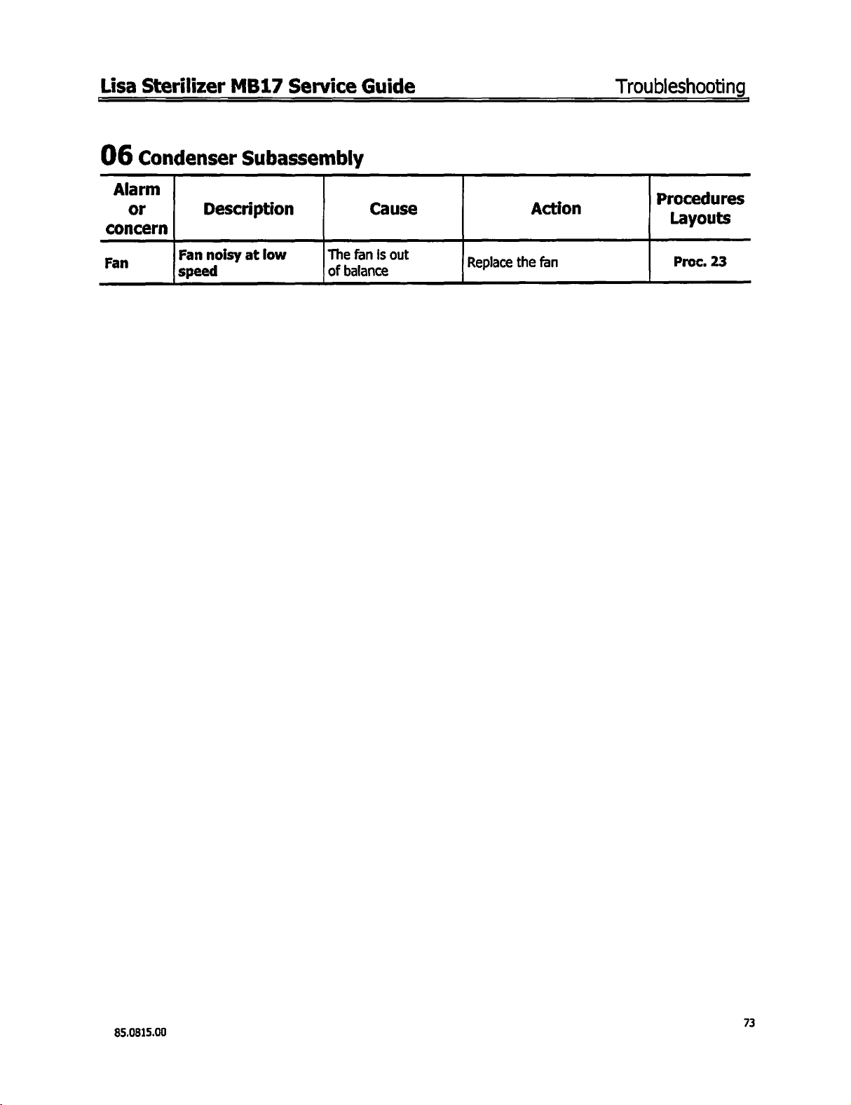
Lisa
Sterilizer
06
Condenser
Alarm
or
concern
Fan
Description
Fan
noisy
speed
MB17
Service
Subassembly
at
low
The
of
balance
Guide
Cause
fan
is
out
Replace
Action
the
fan
Troubleshooting
Procedures
y
Proc.
23
85.0815.00
73
Page 74

Troubleshooting
07
water
Alarm
or
concern
water
Pure
during
signal)
Used
(no
Used
be
Water
the
holes
filling
ignal)
water
warning
water
drained
droplets
used
In
case
phenomena
especially
nearly
full
Tanks
Description
overflows
tank
acoustic
(no
À
overflows
tank
message)
cannot
tank
come
water
of
tank
intensive
is
normal
when
the
use,
tank
of
out
venting
this
is
Cause
Maximum
|
water
Maximum
|
water
Tubing
|
water
pure
level
used
level
,
blocked
ren
level
sensor
sensor
used
sensor
|
Lisa
Sterilizer
Action
sensor
the
sure
Make
replace
Remove,
pin
Check
Make
|
Remove,
Check connections
Make
heating
replace
Clean
where
not
Reminder : If
used
water
drained
growth
Make
ee
Remove,
Check
check
Remove,
check,
connections
sure
the
check,
sure
the
element
it
the
tubing
debris
the
cleaned,
more
for
tanks
in
order
or
any
the
sure
check,
connections
replace
and
Sensor
replace
and
steam
is
coated.
and
came
quality,
water
the
sterilizer
than
must
be
to
avoid
other
sensor
replace
and
generator
try
1
completely
deposits.
MB17
moves
moves
freely
sensor
the
sensor
the
wiring
freely
the
sensor
wiring
If
not
to
find
(load
from
etc.)
is
not
both
week,
algae
freely
moves
sensor
the
wiring
loom
Service
|
rte
loom
~
ET
|
loom
:
out
-
;
Guide
Procedures
Layouts
9
Proc.
Proc.
9
Proc.
15
and
of
the
Proc.
2
9
Annex
3
Owner's
Manual
74
85.0815.00
Page 75

Lisa
Sterilizer
08
Touchscreen
MB17
Service
Guide
Troubleshooting
Alarm
or
concern
Touchscreen
Continuous
the
screen
LCD
Display
Description
not
working
scrolling
A
few
dots
are
missing
Screen
dark
Screen
light
completely
completely
or
blank
of
or
lines
Cause
EMC
protection
Touchscreen
Touchscreen
CPU
board
EMC
protection
Touchscreen
Touchscreen
connector
Touchscreen
[LCD
contrast
Touchscreen
LCD
contrast
CPU
board...
Touchscreen
Touchscreen
film | Replace
itself
flat
film | Replace
itself
flat
,
itself
Replace
cable | Replace
Check
re
Replace
Replace
cable
Replace
Replace
Adjustment
Touchscreen
itself
itself
Replace
Adjustment
Touchscreen
Check
purea
Check
Replace
Check
Action
the
EMC
film
the
touchscreen
the
touchscreen
fuses
the
CPU
board
the
EMC
film
the
touchscreen
the
touchscreen
the
touchscreen
of
the
contrast
submenu
the
touchscreen
of
the
contrast
submenu
jumper
fuses/replace
TS/CPU
X7
ee
nari
the
touchscreen
connections
position
CPU
Procedures
Layouts
y
Proc.
5
Sec.
3,
Tab
15
Proc.
17
Pres.
Proc.
5
in
Proc.
5
in
Layout
deeseereteesesereese
Proc.
Proc.
22
17
5
85.0815.00
connections
Check
the
flat
cable
condition
75
Page 76

Troubleshooting
09
cru
Alarm
concern
Press.
Το
calibration
cancelled | connection
Board
or
+
Description
Condensation/
moisture
used
negatively
the
electronic
p
Droplets
pressure
negatively
the
electronic
components
(EPROM)
sas
from
water
from
sensor
Cause
Determine
tank/cover
the | 9rommets”
tank
affects | replace
the
affects
fitted,
if
not,
emove
tightly
both
the
grommet's | Fix
and
he
Check
condition
Positioning
R
re-fix
the
Lisa
Sterilizer
if
the
new | Replace
with
seals
(sealing) | damaged
tubi
tubing,
are
and
Replace
cut
5mm
cover
the
(1/4
MB17
.
Action
both
water
grommets
the
in.)
properly
grommets
4
an
tank
if
Service
Procedures
Layouts
Proc.
Proc.
Guide
9
1
Water
during
filling
Condensation
moisture
used
negatively
Stored
data
(Date,
Name,
aaj
st
etc.)
cancelled | the
the
components
Droplets
pressure
"
negatively
components
(EPROM)
Water
during
tank
penetration
the
tank Mount
7
from
the | grommets’
water
tank
_|
affects | replace
electronic
from
the
sensor
affects
electronic
penetration
the
filling
the
additional
Determine
tank/cover
fitted,
Check
dition
con
positioning
Remove
re-fix
Mount
if
with
seals
If
not,
both
the
grommet's | Fix
and
(sealing) | damaged
the
tightly
the
additional
the
tubing,
gasket
under
new | Replace
and
cover
are
the
Replace
cut
Smm
gasket
under
the front
both
water
grommets
the
grommets
(1/4
in.)
and
the
front
fascia
tank
properly
fascia
Proc.
36
Proc. 1 and
Proc.
9
36
76
85.0815.00
Page 77

Lisa
Sterilizer
10
Sterilization
MB17
Chamber
Service
Guide
Troubleshooting
Alarm
or
concern
PPh
greaterthan
minutes
Те
sterilization
time
aio | 16-5
could
within
during
Description
phase
потта
pressure:
250°F
31.3
273°F
duration
|
holding
psi
(1.14
(121°C)
ο
(2.16
psi
(134°C)
not
be
reached | injected
20
minutes
PPh
phase
:
20
bar)
at
at
bar)
Cause
Main
water
tank
empty
Excessive
consumption
>14
water
oz./cycle
[7O*MEVCVI
A
steam
|
into
the
generator
Action
Check
minimum
level
sensor
Check steam
|
positioning/condition
Determine
condensation
(EV2/EV4)
properly
chamber
Clean
|FILTERS)
Check
sterilizer
EV1
Check
especially
replace
Check
中
Check
valve
Check
(FILTER
fre
Check
positioning/fixing
(twisted/clamped)
Check
If
water
water
condition
water
braided
door
door
adjustments
3)
water
generator
if
the
2CS
re-vaporization
system
tightness
during
is
working
filter
0
4...
leveling
phase,
PR
needed
pump
(WP)
one
pump
filter
condition
black
tubing
seal
/
PT100
way
Procedures
Lavouts
y
Layout
See
oo
Layout
Layout
Section
λσσλ
Proc.
and
13
45
:
26
21
7,
τησ”
12
1
85.0815.00
Significant
leakage
safety
Check
Check
over
pressure
valves
pneumatic
mİ.
connections
ta
yout
25
m
77
Page 78

Troubleshooting
Alarm
or
concern
Description
Chamber
heater
Cause
External
T°
Lisa
=
sensor
Sterilizer
Action
Check
condition,
fastening
of
the
MB17
position,
external
Service
p
Tay
Layout
Guide
d
ures
you
27
temperature
>
Set + 72°F
A11
A12
A13
(40°C)
The
temperature
chamber
element
set
Chamber
temperature
>
The
the
is
nominal
Theoretical
temperature
>
>137°C/124°C
Pressure
>
>
During
theoretical
from
(according
steam
table),
maximum
heater
is
above
value
heater
Set - 72°F
temperature
chamber
below
278.6°F/255.2°F
33.4
2.30
read
T°/ P correlation
(40°C)
heater
the
value
psi/18.0
bar/
1.24
PR
phase,
deducted
T°
pressure,
saturated
is
above
the
threshold
PT100
calibration
board
CPU
cancelled
of
the
the | CPU
of
psi
bar
board
Chamber
overload
External
|PT100
CPU
cancelled
CPU
CPU
thermal-
open
T°
broken
board
board
board
broken
sensor
calibration
broken
PT100
T°
sensor
calibration
CPU
CPU
replacement + calibration|
Reset/replace
overload
Sensor
calibration
CPU
Check
element
the
on
if
not,
CPU
,
thermal-
replacement
.
the
chamber
power
board,
CPU
replace
replacement + calibration | Calibration
heating
voltage
the
CPU
output
board | EPROM1
Layouts
Calibration
board
service
EPROM
Layouts
Calibration
board
Layouts
board
service
EPROM
22
23
and
+
1
Proc.
32
Proc. 24
22
23
and
+
and
23
+
1
22
78
85.0815.00
Page 79

Lisa
Sterilizer
Alarm
or
concern
A14
MB17
Description
Theoretical
temperature
<
273.2
<
134°C/
Pressure
<
<
2.03
00009
e
deducted
pressure,
saturated
correlation
below
threshold
F/
249.8
121°C
”
29.4psi/15.1psi
bar/1.04
holding
tneoretica
from
according
steam
table,
the
minimum
Service
F
bar
ome
read
T°/
P|
is
O
Guide
Cause
Main
water
empty
|Excessive
consumption
>
14
>
0.4
|
Insufficient
injected
|
steam
water
oz./
cycle
liters/cycle
into
generator
tank
water
the
Troubleshooting
p
Action
Check
minimum
level
sensor
Check
steam
[Positioning/conditton
Determine
condensation
(EV2/EV4)
|
Working
Clean
(FILTER
р
Check
for
Check
especially
replace
|
Check
Check
way
Check
(FILTER
Check
adjustments
properly.
chamber
5)
sterilizer
level
00...
EV1
if
water
water
valve
water
3)
door
water
generator
PT100
||
if
the
2CS
re-vaporization
system
hone
tightness
during
needed
Is
filter
eh
cee
work
surface
PR
phase,
pump
(WP)
pump
one
filter
condition
seal/door
|
|
|
Pe
|
|
Layouts
d
Lave
rayout
Sec
Layout
ures
youts
Layout
aS
Sec.
Proc.
37
Proc.
26
21
7,
and
13
9
|
1
,
12
as
85.0815.00
Significant
Internal
Main
water
sen
T°
<
273.2ºF/
|“
134°C/
(Steam
temperature)
During
the
steam
read
is
minimum
249.8ºF
121°C
holding
below
time,
temperature
the
threshold
empty
|
Excessive
consumption
>
14
oz./cycle
>
0.4
liters/cycle
leakage
PT100
T°
tank
water
Check
over
pressure
safetyvalves
Check
pneumatic
Check
internal
sensor
positioning
Check
level
Check
|
positioning/condition
vaporization
system
Clean
(FILTER
Check
for
condition
minimum
sensor
steam
Determine
works
chamber
5)
sterilizer
level
μμ”...
connections
PT100
T°
and
water
generator
|...
if
the
2CS
re-
(EV2/EV4)
properly
filter
work
surface
μμ
|
PT100
|
μυ.
Layout
Layouts
η
See
oo.
Proc.
ayout
Sec.
Proc.
37
37
9
—
Lc.
1
79
Page 80

Troubleshooting
Alarm
or
concern
contin
red
Description
T°
sen
|<
273:2°F/249.8°F
<
134°C/
(Steam
temperature)
During
the
read
holding
steam
is
,
minimum
121°C
time,
temperature
below
the
Insufficient
injected
steam
Significant
threshold
CPU
board
Lisa
Cause
water
into
the
generator
leakage
calibration
Sterilizer | MB17
Check
EV1
especially
replace
[Check
Check
[way
Check
(FILTER
Check
adjustments
©
|
Check
eck
safety
Check
CPU
Check
adjustments
during
if
needed
water
water
valve
oo...
water
3)
door
over
over
valves
pneumatic
calibration
door
Action
tightness
PR
phase,
pump
(WP)
pump
one
filter
condition
seal/door
pressure
pressure
connections
seal/door
Service
Proced
Layouts
|
|.
Layouts
and
Calibration
board
service
EPROM
Layouts
aG*
Guide
Lan
Layout
Layout
o
Layout
you
and
US
23
and
+
1
13
ts
32
21
7,
13
25
22
7,
ーー
12
12
Significant
sen
T°
>
278.6ºF/
>
137°C/
(Steam
A16
temperature)
the
steam
read
Is
maximum
255.2ºF
124°C
ο
temperature
above
the
threshold
|
Internal
sensor
πο
CPU
cancelled
leakage
PT100
αμ
board
ard
T°
calibrati
calibration
Check
over
pressure
valves
safety
рот
Check
pneumatic
Check
Internal
condition
CPU
and
calibration
:
connections
T°
sensor
positioning
Layout
Layout
25
37
μ.μ...
Layout
Calibrati
board
service
EPROM
22
ration
+
1
80
85.0815.00
Page 81

Lisa
Sterilizer
Alarm
or
concern
αι
A18
Chamber
|
broken
The
PT100
broken
Internal
emperature
broken
The
PT100
broken
MB17
Description
chamber
Tº
sensor
or
disconnected
chamber
chamber
T°
sensor
or
disconnected
Service
heater
External
external
is
sensor
internal | Sensor
is
|Sensor
Internal
Guide
Cause
PT100
PT100
Action
Te — |
Te — [connections
Connections
Replace
Check
Replace
PT100
PT100
PT100
T°
T°
|
T°
sensor
sensor
sensor
Troubleshooting
Procedures
vouts
Proc.
24
NN
"
Proc.
31
°
85.0815.00
81
Page 82

Troubleshooting
20
steam
Generator
Lisa
Sterilizer
MB17
Service
Guide
Alarm
or
concern
A21
Description
Steam
temperature
>
(70°C)
The
the
is
maximum
generator
Set + 126ºF
temperature
steam
generator
above
the
threshold
of
Main
empty
Cause
water
tank
Check
level
Check
Action
minimum
sensor
steam
pasitioing/condltion
Determine
condensation
Excessive
consumption
>14
(>0.4
|
Insufficient
injected
steam
water
oz./cycle
liters/cycle)
water
into
the
generator
evo’)
POP
Clean
=
|(FILTER
Check
|--------.-...............s..s
Check
especially
replace
Check
Check ー n
Ne
vaivecondition
Check
if
system
ln
chamber
5)
sterilizer
EV1
during
if
needed
water
기”
Wa
“ith
water
water
generator
PT100
|
the
2CS
re-vaporization
is
working
filter
|
leveling
tightness
PR
phase,
pump
(WP)
pump
one
way
iii
filter
(FILTER
Procedures
la
you
Proc.
Layout
See
Section
Proc.
fesses
Proc.
Layout
3)
its
9
45
1
37
26
21
82
85.0815.00
Page 83

Lisa
Sterilizer
MB17
Service
Guide
S
Troubleshooting
М
Alarm
or
concern
A22
A23
Description
o
<
194°F
The
the
Is
below
minimum
Steam
προ
(90°C)
temperature
steam
the
threshold
of
generator
generator
open
overheating
CPU
Steam
eating
CPU
generator
calibration
provoking
and
overload
=
Ream
Cause
am
generato”
after
(A21)
board
generator
element
board
steam
T°
channel
cancelled
overheating
the
thermal
opening
generator
Action
Reset
the
thermal
and
check
causes
as
described
Check
7
heating
voltage
board,
CPU
board
Check
heating
ohmmeter,
heating
CPU
calibration
Check
|sensor
Replace
in
the
steam
element
output
if
none,
the
conductivity
element
if
open
element
ea
PT100
connections
PT100
overload
and
A21
generator
power
on
the
CPU
replace
with
an
replace
|.
sensor
actions
the
of
the
the
Procedures
la
outs
γ
Layout
Proc.
Diaanostic
Proc.
Layout
Calibration
board
service
EPROM
Proc.
Layout
29
17
wena
15
22
+
1
39
22
85.0815.00
The
steam
generator | CPU
PT100
T°
broken
sensor
or
is
disconnected | calibration
board
steam
generator
T°
channel | CPU
cancelled
calibration
Calibration
service
EPROM
1
83
Page 84

Troubleshooting
30
Vacuum
Pump
_Lisa
Sterilizer
MB17
Service
Guide
Alarm
or
concern
Description
3
minutes
phase
start:
(020
bar)
・
A31 | During a vacuum
(PV1-6/DV),
the
lowest
pressure/vacuum
not
peo
-2.9
(-0.20
bar)
aft
er
o
2.9
psi | CPU
phase
achieved
is
psi
Cause
Vacuum
Pressure
board
Door
seal
pump
sensor
Action
Check
vacuum
condition,
electrical
[000000000
Check
head
and
|
Black
Pressure
replace
Check
power
CPU
the
Check
condition
Door
positioned
collar:
Check
function
Check
adjustment
Check
and
pneumatic
connections
vacuum
membranes,
O-rings
braided
sensor
CPU
the
vacuum
voltage
board.
If
CPU
board
door
seal
(broken)
seal
not
against
door
locking
door
locking
and
EV2-3-4
switching
pump
and
pump
valves
tubing
jammed
broken,
board
pump
output
on
none,
replace
properly
chamber
system
switches
condition
tightness
the
Procedures
Layouts
у
Layout
|...
Layout
Layout
Diagnostic
menu
ay
outs
7
Diagnostic
menu
33
23
23
16
84
Electro-valves
Replace
Replace
Electro-valve(s)
CPU
board
Proc.
20
and
Proc.
17
85.0815.00
Page 85
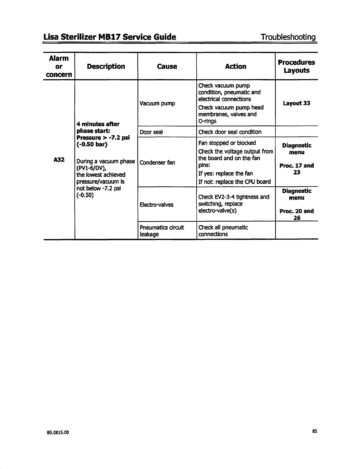
Lisa
Sterilizer
Alarm
or
concern
MB17
Description
Service
Vacuum
Guide
Cause
pump
Action
Check
vacuum
condition,
electrical
Check
pneumatic
connections
vacuum
pump
pump
Troubleshooting
Procedures
γ
and
head
Layout
33
A32
4
minutes
phase
Pressure > -7.2
(-0.50
LD
the
lowest
pressure/vacuum
not
below
(-0.50)
after
start:
bar)
Vy
achieved
-7.2
psi
Door
seal
psi
h
phase | Condenser
is
Electro-valves
Pneumatics
leakage
fan
circuit
membranes,
O-rings
Check
Fan
stopped
Check
the
board
pins:
If
yes:
If
not:
Check
switching,
electro-valve(s)
Check
connections
valves
door
seal
or
the
voltage
and
replace
replace
EV2-3-4
replace
all
pneumatic
condition
blocked
on
the
the
tightness
and
output
the
fan
fan
CPU
from
Proc.
board
Diagnostic
and
Proc.
Diagnostic
menu
17
and
23
menu
20
and
26
85.0815.00
85
Page 86

Troubleshooting
Lisa
Sterilizer
MB17
Service
Guide
Alarm
or
concern
A33
Description
The
value
of
vacuum
run < -11.6
(-0.80
The
|llevel
vacuum
sufficient
compensating
additional
calculated
be
pulse
bar)
global
obtained
pulses
and
6th
pulse
reached
vacuum
th
the
6
to
be
psi
after 5 |
was
not
the
cannot
Cause
V
acuum
Condenser
Door
Electro-valves
Pneumatics
leakage
pump
fan
seal
circuit
Action
Check
vacuum
condition,
electrical
Check
vacuum
membranes,
O-rings
Fan
stopped
Check
the
the
board
pins:
If
yes:
replace
If
not:
replace
Check
door
Check
EV2-3-4
switching,
electro-valve(s)
Check
all
connections
pump
pneumatic
connections
pump
valves
or
blocked.
voltage
and
on
the
the
seal
condition
tightness
replace
pneumatic
and
head
and
output
from
the
fan
fan
CPU
board
and
Procedures
Layouts
y
Layout
Proc.
Diagnostic
Proc.
Layout
17
23
menu
20
26
33
and
and
22
CPU
board
cancelled
The
10
last
cycles
required
additional
pulse
Sterilization
A34
guaranteed.
additional
ensures
vacuum
can
will
within
the
vacuum
Is
The
6”
the
required
level.
go
on
sterilizing
get a new
10
new
6º
pulse
The
user
alarm
cycles.
Overloaded
but
calibration
cycle
CPU
calibration
Refer
the
maximum
porous
FOLLOW
to
the
load
;
cycle table
solid
and
mass
A33
for
Calibration
board
service
EPROM
+
1
86
85.0815.00
Page 87

Lisa
40
Water
Sterilizer
water
Concern
pump
Pump
description
.
is
noisy
MB17
。 。
Service
One
Pump
Guide
Cause
way
valve
Itself
spring
Action
Song
adjust
|
Check
pump
Check
rubber
support
Check
condition
braided
positioning/fixing
Troubleshooting
Procedures
Layouts
valve
fixing/positioning
Je
black
tubing
(twisted).
|...
Layout
|...
Diagnostic
41
Water
pump
pump
d k
doesn't
wor!
Pump
Pump
CPU
board
connections
Itself
Replace
Check
connections
Replace
Check
voltage
If
pump/CPU
the
not:
the
water
(inverted
the
water
water
output
replace
pump
electric
pump
pump
on the
the
CPU
wires)
power
board.
board
menu
Proc.
16
Diagnostic
menu
Proc.
16
i
Diagnosti
Proc.
17
i
5
85.0815.00
87
Page 88

Troubleshooting
50
Door
Alarm
or
concern
At
cycle
If
within
is
detected.
If
the
switch
Message
"Door
locking | detected
problem" | (system
Locking
Description
start,
the
locking
6"
this
switch
is
reached
|The
UNLOCKED
switch
or
did
could
not
motor
is
not
or
ο
not
move)
not,
System
is
powered
reached,
follow
be
blocked
|
Cause
until
the
motor
the
listed
possibilities © or
Door
seal
Door
locking
DOOR
LOCKED
switch
CPU
board
the
DOOR
is
reversed
system
oC
Lisa
Sterilizer
LOCKED
until
Check
fe
Door
Check/adjust
motor
Check
condition
LOCKED
SALE
O
MA...
Replace
locking
Check
voltage
CPU
CPU
Action
switch
the
UNLOCKED
@
door
seal
out
consumption
the
presence
of
switch
ο
으으
and
switch
the
motor
output
board,
board
MB17
is
activated.
switch
seal
condition
of
housing
door
locking
and
the
DOOR
actuator
이
으으으
+
LOCKED
adjust
the
board
power
on
the
if
not,
replace
Service
Proc
switch
ee
n
door
the
Guide
edures
y
Layouts
Layout
Door
device
p
Door
device
Diagnostic
Diagnostic
Proc.
Proc.
7
10
test
11
roc.
test
menu
menu
17
10
If
the
motor
is
powered
Door
locking
motor
does
not
move,
replace
entire
door
locking
and
the
system
Diagnostic
menu
Door
test
device
85.0815.00
Page 89

Lisa
Alarm
or
concern
A52
Sterilizer
Description
The
UNLOCKED
switch
detected
blocked)
Note:
device
connected
(Layout
The
switch
during
could
the
can
10)
UNLOCKED
is
the cycle
MB17
o
(system
door
be
opened
Service
a >
not
be
test
tom
to
Guide
Cause
E
Door
CPU
DOOR
locking
board
system | electrical
UNLOCKED
switch
Door
switch
board/CPU
Check
тееееннее-
[Switch
door
Door
seal
Check
door
Check
the
power
voltage
CPU
board
replace
Check
and
the
p
the
condition
acluator
Replace
locking
Check
connections
switch
door
Action
seal
condition
out
of
housing
locking
consumption
reverse
(relays),
CPU
presence
and
switch
and
motor
output
board
of
the
adjust
board
board/CPU
wiring
motor
on the
if
none,
the
Troubleshooting
S
7
10
test
17
test
11
test
test
door
loom
Procedure
Layouts
Layouts
Layout
Door
device
Proc.
. .
Diagnostic
Door
device
Proc.
Door
device
Door
device
85.0815.00
89
Page 90

Troubleshooting
Alarm
or
concern
END
Description
Door
at
the
cycle
Note:
the
|
device
connected
unlock
(Layout
remains
end
door
can
In
the
system
10).
of
be
order
locked
the
test
to
Cause
Door
switch switch
board/CPU
Door
CPU
locking
board
motor
Lisa
Sterilizer
Moisture
board,
아아아
Check
connections
Check/adjust
electrical
if
broken,
door
Check
power
CPU
Action
on the
DOOR
remains
door
switch
motor
replace
locking
the
reverse
voltage
board
(relays),
MB17
door
switch
UNLOCKED
ON
아아아
board/CPU
and
wiring
loom
door
locking
consumption,
the
entire
system
moto
output
on
the
if
none,
Service
Procedures
Y
Door
device
Layout
Door
device
Diagnostic
menu
Schedule
Door
device
Guide
test
10
test
16
test
replace
DOOR
Door
can
be
opened
but
the
END
screen
remains
displayed
|DOOR
|switchremains
[activated
CLOSED
oo
actuating
—|Ciean,
|--------............................
Check
and
conditions/adjustments
the
CPU
board
CLOSED
axle
lubricate
DOOR
actuator
switch
blocked.
or
replace
CLOSED
Di
iagnostic
it | Schedule
Door
switch | “00r
device
:
menu
16
test
90
85.0815.00
Page 91

Lisa
Sterilizer
60
Electro-Valves
Alarm
or
concern
dun
ppi-5/
A63
is
below
(-0.70
infected
MB17
Description
0
dre
-
negative
still
-10.1
bar)
In
Service
d
after
sec.
guise
pph),
toa
and
psi
chamber
the
Guide
Cause
EV4
EVI
board
CPU
tank
water
Main
empty
Insufficient
Injected
steam
water
the
into
generator
Troubleshooting
p
Action
Determine
switches
not,
replace
Determine
switches
not,
replace
Check
voltage
board,
CPU
Check
level
[Check
Check
[Valvecondition
Check
|
ooO|...........................--------
Check
positioning/fixing
(twisted/clamped)
if
the
when
energized,
check
connection
the
valve
if
the
when
energized,
check
connection
valve
the
EV1-4
the
output
if
board
minimum
sensor
water
water
water
braided
on
none,
pump
pump
00000
filer
black
valve
if
or
valve
if
or
power
CPU
the
replace
water
(FILTER
the
|
(WP)
one
way
3)
tubing
d
rocedures
Layouts
Diagnostic
menu
Proc.
20
Diagnostic
menu
26
Proc.
Diagnostic
menu
17
Proc.
9
Proc.
"
Layout
21
85.0815.00
91
Page 92

Troubleshooting
70
Distilled/De-Mineralized
Concern
White
dots
chamber,
trays
and
description
the
on
tray
support
Poor
load,
Load
dried
sterilization
Quality
Water
Cause
water
quality
rinsed
not
prior
to
of
the
Lisa
Sterilizer
Check
to
another
and
Load
must
drying | Follow
Action
water
quality.
water
be
chapter
MB17
supplier
rinsed
05
Drying
Service
Change
and
dried
References
Attached
EN13060
Water
Owner's
pente
Preparation
of
problems
Guide
E
quality
2
che
the load
Preparation
Cleaning
The
dentine,
damage
>
b
b
of
the
instruments
and
blood,
the
sterilizer.
Clean
the
using
an
Remove
thoroughly,
Lubricate
all
of
the
Load
instrument
to
be
sterilized
etc.)
These
instruments
ultrasonic
traces
and
in
accordance
cleaner.
of
disinfectant
then
(from
substances
immediately
dry.
with
Owner's
must
be
from
the
manufacturer's
clean
can
after
use.
the
Manual - Annex
and
free
from
all
damage
product
the
objects
Follow
the
as
this
instructions.
manufacturer's
types
placed
may
2)
of
residue
cause
(such
in
the
trays
instructions
corrosion
as
fragments,
and
can
on
heating.
also
when
Rinse
92
85.0815.00
Page 93

Lisa
Sterilizer
MB17
Service
Guide
Troubleshooting
Water
Suggested
Evaporate
Silicon
Iron
Cadmium
Lead
ron 이 168
Chloride
Phosphate
Conductivity
pH
Appearance
Hardness
NOTE
NOTE
Quality
maximum
monoxide,
value
1:
2:
residue
Condensate
(EN13060
limits
Table
SiO.
eect
excluding
(at
68°F)
(20°C)
Do
not
use
water
generation.
invalidate
Contaminated
the
is
Annex
of
contaminants
B.1:
Contaminants
colorless,
contaminated
water
manufacturer's
produced
from
warranty
steam
E)
as
specified
of
Feed
10
mg/liter
1
mg/liter
0.2
mg/liter
0.005
0.05
0.1
mg/liter
2
mg/liter
0.5
mg/liter
15
5to7 5to7
clean,
0.02
mmol/liter
at
levels
greatly
evacuated
for
water
condensate
water
mg/liter
mg/liter
us/cm
without
exceeding
reduces
or
guarantee.
from
used
and
feed
those
given
the
working
the
sterilization
for
steam
water
colorless,
in
life
sterilization
Condensate
1.0
mg/kg
0.1
mg/kg
0.1
mg/kg
0.005
mg/kg
0.05
mg/kg
0.1
mg/kg
0.1
mg/kg
0.1
mg/kg
3
us/cm
Clean,
without
0.02
mmol/liter
this
table
for
steam
of a sterilizer
chamber.
and
can
85.0815.00
93
Page 94

Troubleshooting
_
Lisa
Sterilizer
MB17
Service
Guide
94
85.0815.00
Page 95

Lisa
Sterilizer
MB17
Service
Guide
Repair
Procedures
Section 6 —
Repair
Chamber
Chamber
Chamber
Composite
Composite
Composite
Condenser
Cover
CPU
Door
Door
Door
Door
EPROM,
EV1-EV3
EV1-EV3
EV2-EV4
EV5
EV5
External
Fascia/cover
Mains
Pressure
Printer
Rear
Rear
Steam
Steam
Steam
Steam
Thermal-overload
Touchscreen
Vacuum
Vacuum
Vacuum
Water
Water
Water
heating
internal
outlet
door
fascia
service
and
board
locking
locking
seal
Data
coil
subset
subset
subset
subset
filter
chamber
filter
pack
safety
interface
housing
support
generator
generator
generator
generator
pump
pump
pump
pump
pump
tank
encoder
motor
and
seal
cover
frame
one-way
Repair
element
PT100
T°
filter
cover
door
condenser
board
(DT
x.x)
and
solenoid
PT100
sensor
valves
housing
(including
heating
PT100
thermal-overload
membrane
silencer
element
T°
valve
sensor
fan
program
subsets)
sensor
kit
spring
Procedures
(EU
x.x)
Procedure
#|
33
31
37
30
23
17
11
10
25
28
26
20
21
38
24
36
12
19
18
13
29
14
15
39
22
32
27
34
16
35
2
4
1
3
7
5
8
9
Page
#
119
117
122
97
99
117
112
97
107
98
103
102
101
113
115
114
109
110
123
113
121
104
108
107
104
116
105
106
123
111
118
100
101
114
120
106
120
102
85.0815.00
95
Page 96

Repair
Procedures
Lisa
Sterilizer
MB17
Service
Guide
How
the
Procedures
to
Use
Repair
Use
these
mounting
The
procedures
use
the
following
procedures
layouts
in
Chapter 7 and
in
this
symbols:
in
combination
section
are
Operation
Refer
layout
with
the
the
troubleshooting
presented
to
be
followed
Question
to
answer
to
service
number
removal,
as
flow
replacement
charts
chart
diagrams,
in
Chapter
and
4.
which
96
85.0815.00
Page 97

Lisa
Sterilizer
MB17
Service
Guide
Repair
Procedures
Procedure 1 —
(
START
Cover
removal
Remounting
END
Replace
)
Cover
Layout
1
Procedure 2 —
(
START
Composite
removal
cover
Remounting
END
door
Replace
)
Composite
Layout
2
Door
Cover
85.0815.00
97
Page 98

Repair
Procedures
Lisa
Sterilizer
MB17
Service
Guide
Procedure 3 —
Replace
Door
START
Cover
removal
D
oor
composite
removal
Door
removal
Composite
removal
Door
mounting
without
Close
the
seal
the
the
gap
and
mounting
fascia
door.
between
collar.
si
]
it
|
|
fascia
|
|
Check
door
chamber
^
Layout
fl
Layout
„T
Layout
C
Layout
1
2
3
4
98
^
Layout
Layout
(
Layout
TT]
Layout
Layout
12| | >1/32inch
13
12
3
13
Irregular
all
(Imm)
gap
around
1/32
in
ae
gap
~
Layout
一
一
一
Layout 3 |-
Layout
(Imm)
“a,
12
—
一
13
>
Check
door
motor
locking
current
consumption
[=
+/-08R
Cover
г
Layout
mounting
10
85.0815.00
Page 99

Lisa
Sterilizer
MB17
Service
Guide
Repair
Procedures
Procedure 4 —
START
Cover
removal
Door
composite
removal
Door
removal
Front
panel
Remounting
Replace
removal
Composite
Layout
„Z
Layout
Layout
Layout
1
2
3
4
Fascia
1
END
85.0815.00
Page 100

Repair
Procedures
Lisa
Sterilizer
MB17
Service
Guide
Procedure 5 —
Quick
Procedure
START
Cover
removal
| !
Remove
composite
fixing
release
hand
Twist
composite
touchscreen
Remounting
door
screws
both
side
clips.
|
the
as
much
possible.
|
Replace
eplace
fascia
and
left
fixing
top
fascia
as
th
the
Replace
Layout
L
ayou
の
Layout
END
Touchscreen
1
t47
|
47
Standard
Composite
Procedure
START
Cover
removal
Door
composite
removal
Door
removal
removal
Touchscreen
replacement
Remounting
END
|
|
.
fascia
T
Layout
Layout
CI
.
Layout
Layout
|
Layout
y
1
2
3
4
5
100
 Loading...