

Page 1

VRO 300M
™
REFERENCE MANUAL
Page 2
Readout Parameter Access Code
An access code must be entered before machine-related parameters can be
set or changed. This prevents inadvertent adjustments to the setup
parameters.
IMPORTANT
The access code is 8891
Refer to the Setup section. Begin by pressing the
softkey. Press the 8, 8, 9, 1, and
SETUP
key then the
ENTER
keys. The readout is now
ready for machine parameter setting operations.
IMPORTANT
Supervisors may wish to remove this page from the Reference
manual after initially setting up the readout system. Retain in a
safe place for future use.
INSTALLATION
SETUP
Page 3

Page 4

Warranty
ACU-RITE Products and accessories are warranted against defects
in material and workmanship for a period of three years from the
date of purchase. ACU-RITE will, at its option and expense, repair
or replace any part of the ACU-RITE product that fails to meet this
warranty. This warranty covers both materials and factory labor. In
addition, authorized ACU-RITE service representatives will provide
service labor (field service) for a period of one year at no charge.
Notice of the claimed defect must be received by ACU-RITE within
the warranty period.
This warranty applies only to products and accessories installed
and operated in accordance with this reference manual. ACU-RITE
shall have no obligation, with respect to any defect or other
condition caused in whole or in part by the customer’s incorrect use,
improper maintenance, modification of the equipment, or by the
repair or maintenance of the product by any person except those
deemed qualified by ACU-RITE.
Responsibility for loss of operation or diminished performance due
to conditions beyond ACU-RITE’s control cannot be accepted by
ACU-RITE.
The foregoing warranty obligations are in lieu of all expressed or
implied warranties. ACU-RITE INCORPORATED shall not be liable
under any circumstances for consequential damages.
30 Day Red Carpet Warranty
All ACU-RITE products are covered by a 30-day Red Carpet
Warranty. If in the first 30 days this product fails for any reason,
repack it in the original packaging materials and contact your
Authorized ACU-RITE Distributor for return procedures.
Page 5

Table of Contents VRO 300M
Introduction..................................................................................................................... 1
A Tour of the Readout..................................................................................................1
Front and Back Views...............................................................................................1
Connections..............................................................................................................2
Keypad...........................................................................................................................3
Display...........................................................................................................................4
Readout and Program Displays..................................................................................5
Power-On Position Recovery......................................................................................7
Position-Trac ............................................................................................................7
Readout Operations....................................................................................................... 8
Clear Key.......................................................................................................................8
Absolute and Incremental Displays............................................................................8
Absolute Display.......................................................................................................8
Incremental Display..................................................................................................8
Zeroing the Displays ....................................................................................................9
Absolute Zero...........................................................................................................9
Moving the Absolute Zero.......................................................................................11
Zeroing at a Center Line.........................................................................................12
Incremental Zero.....................................................................................................12
Presetting....................................................................................................................13
Absolute and Incremental Presets..........................................................................14
Center-line Presets.................................................................................................15
Presetting Using the POS Key...................................................................................15
Near Zero Warning .....................................................................................................16
Tool Offsetting............................................................................................................17
Defining the Offset Direction...................................................................................17
Using Tool Offsets..................................................................................................18
Program Operations ....................................................................................................19
Creating a Program....................................................................................................19
Saving and Loading Your Programs ........................................................................20
Alphabet Entry........................................................................................................21
Running a Program....................................................................................................22
Tool Steps ..............................................................................................................22
Positioning Steps....................................................................................................22
Programming a Tool Offset.......................................................................................23
Tool Steps...................................................................................................................24
Position Steps.............................................................................................................25
Mill Steps.....................................................................................................................26
Bolt Circles..................................................................................................................27
Hole Frame and Hole Array........................................................................................28
Row of Holes...............................................................................................................29
Rectangular Frame.....................................................................................................30
Repeats........................................................................................................................31
Mirror Images..............................................................................................................32
Explode........................................................................................................................33
Teaching a Position....................................................................................................34
Page 6

VRO 300M Table of Contents
Other Features.............................................................................................................. 35
Calculator....................................................................................................................35
Trig Functions.........................................................................................................35
Tilt Angle Calculator................................................................................................36
RPM Calculator......................................................................................................37
Printing........................................................................................................................38
Remote Interface ........................................................................................................40
Requesting Information...........................................................................................40
Keypad Commands................................................................................................41
Job Clock ....................................................................................................................42
Reference Tables........................................................................................................42
Setup ..............................................................................................................................43
Job Setup....................................................................................................................44
Tool Library.............................................................................................................44
Display Resolution..................................................................................................45
Scale Factor ...........................................................................................................45
Near Zero Warning.................................................................................................46
Linear Error Compensation.....................................................................................47
Anchoring the Segments........................................................................................48
Compensation Entry Methods................................................................................49
Job Clock................................................................................................................52
Feed Rate Units......................................................................................................52
Remote Switch.......................................................................................................52
Installation Setup........................................................................................................53
Display Configuration..............................................................................................53
Encoder Setup........................................................................................................54
Serial Port...............................................................................................................55
Parallel Port............................................................................................................56
Protection ...............................................................................................................56
Graph Orientation...................................................................................................57
Installation .....................................................................................................................58
Readout Specifications ...............................................................................................60
Troubleshooting........................................................................................................... 61
Page 7
!
This symbol alerts you to the fact that
important information concerning the
installation and operation of this readout
has been included in this manual.
VRO 300M
Keep these instructions in a secure place
for future reference.
Page 8
VRO 300M Introduction
Introduction
ACU-RITE’s VRO 300 readout series provides the application-specific features
required for you to obtain the most productivity from your manual machine
tools.
The VRO 300M is designed specifically for milling and drilling applications.
Special features include immediate part-view graphics, bolt hole patterns,
tool offsetting, part programming, reference tables, and calculators.
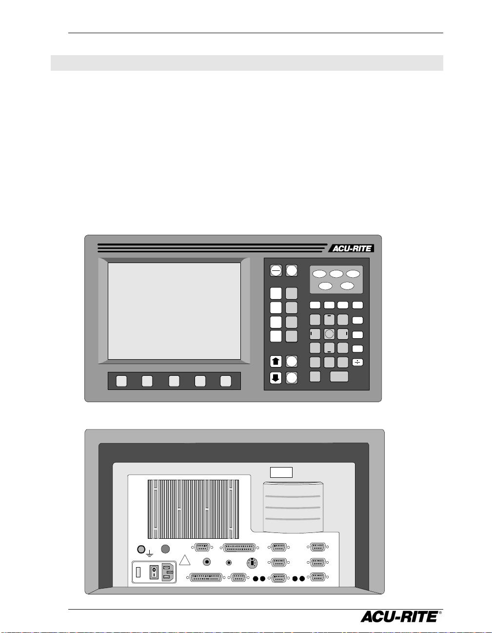
A Tour of the Readout
Front and Back Views
ABS
VIEW
INCR
X
Y
Z
W
ZERO
ZERO
ZERO
ZERO
ZERO
PGM
DRO
MILL HOLES MORE
TOOL
SETUP
INFO MM
7 8 9
4 5 6
1 2 3
0 +/-
.
CLEAR ENTER
POS
CALC
+
-
X
CONTRAST
EXT VIDEO
PENDANT TOUCH PROBE
!
EDGE FINDER
PN 200x00x
SN 9766554
CFI
SERIAL PORTPARALLEL PORT
INPUT 6
INPUT 4
INPUT 2
P2
P4
INPUT 5
INPUT 3
INPUT 1
P1P3
1
Page 9
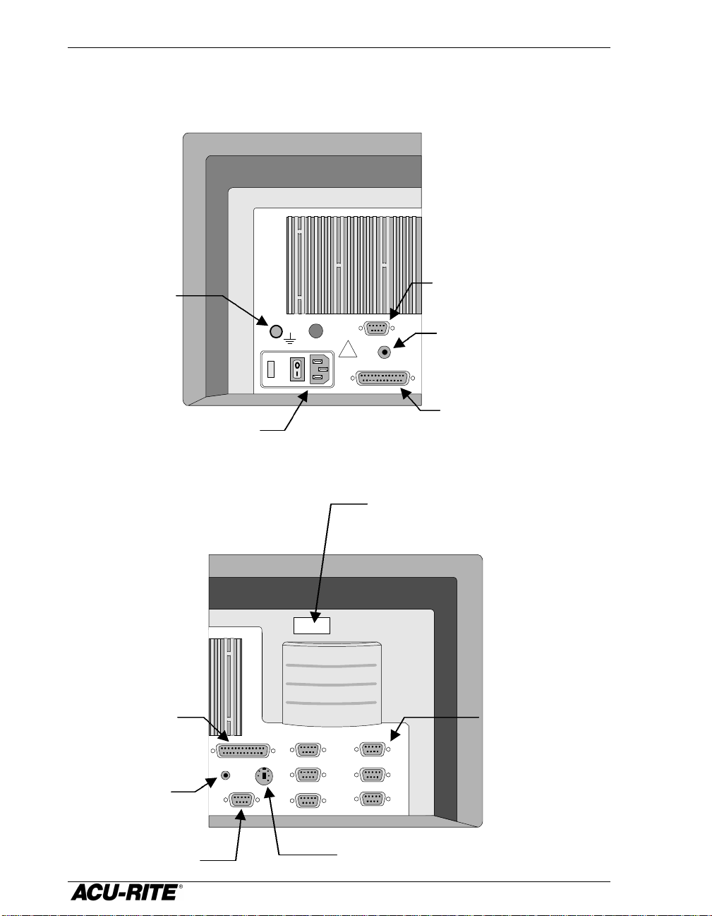
Introduction VRO 300M
Encoder inputs
Ground wire
Model number and
Touch probe input
Serial (RS-232) port
Control function
Connections
External video
connection
Power switch and
voltage selector
CONTRAST
!
EXT VIDEO
PENDANT
PARALLEL PORT
output
Remote switch
(pendant) input
Parallel (printer)
port
interface port
edge finder
Electronic
input
EDGE FINDER
SERIAL PORT
CFI
TOUCH PROBE
PN 200x00x
SN 9766554
INPUT 6
INPUT 4
INPUT 2
Serial number
INPUT 5
INPUT 3
INPUT 1
2
Page 10
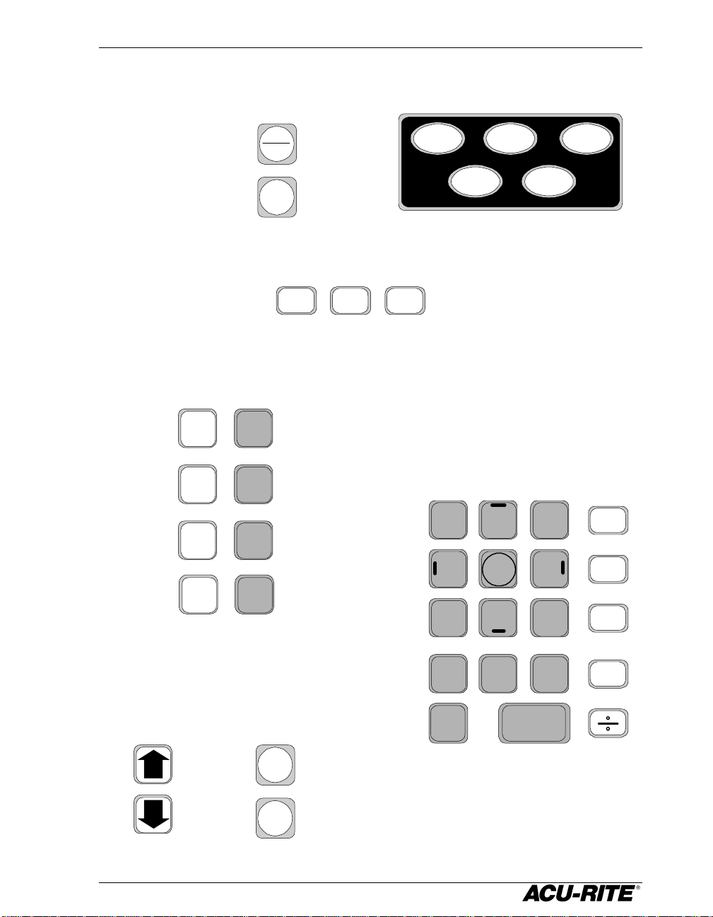
VRO 300M Introduction
Selects absolute or
View the part graphic
Application-specific
English / metric
System setup
System
and help
Begin a preset
Zero an axis
Move up or
Lets you switch
Some of the
Enter all numeric values
functions
Keypad
incremental display
or the position displays.
information
X
Y
Z
W
ZERO
ZERO
ZERO
ZERO
ABS
INCR
VIEW
INFO
conversion
number keys are
MM
also used for
SETUP
tool offset
direction.
TOOL POS
function keys
parameters
with these
87 9
54 6
21
3
MOREHOLESMILL
CALC
+
-
down on the
screen
between
programming and
Digital ReadOut
displays
PGM
DRO
. 0
CLEAR
3
+/-
ENTER
x
Handy
calculator
Page 11
Introduction VRO 300M
213
4
3
4
2
1
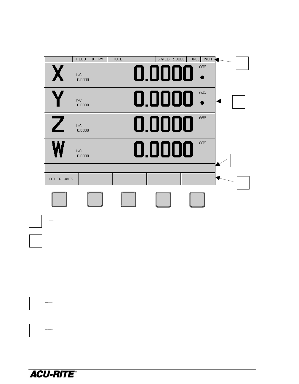
Display
The display screen is divided into four sections.
Status bar – displays the feed rate, current tool, scale factor, job
clock, and inch/mm status.
Information screen – displays information for the task being
performed.
• Used as a readout, the screen will display the current position for
each axis.
• When programming, the program steps and the part graphic will
be displayed.
Message line – operator prompts and messages will appear here.
Softkeys – variable functions appear here; functions are selected by
pressing the hard key directly below the softkey.
4
Page 12
VRO 300M Introduction
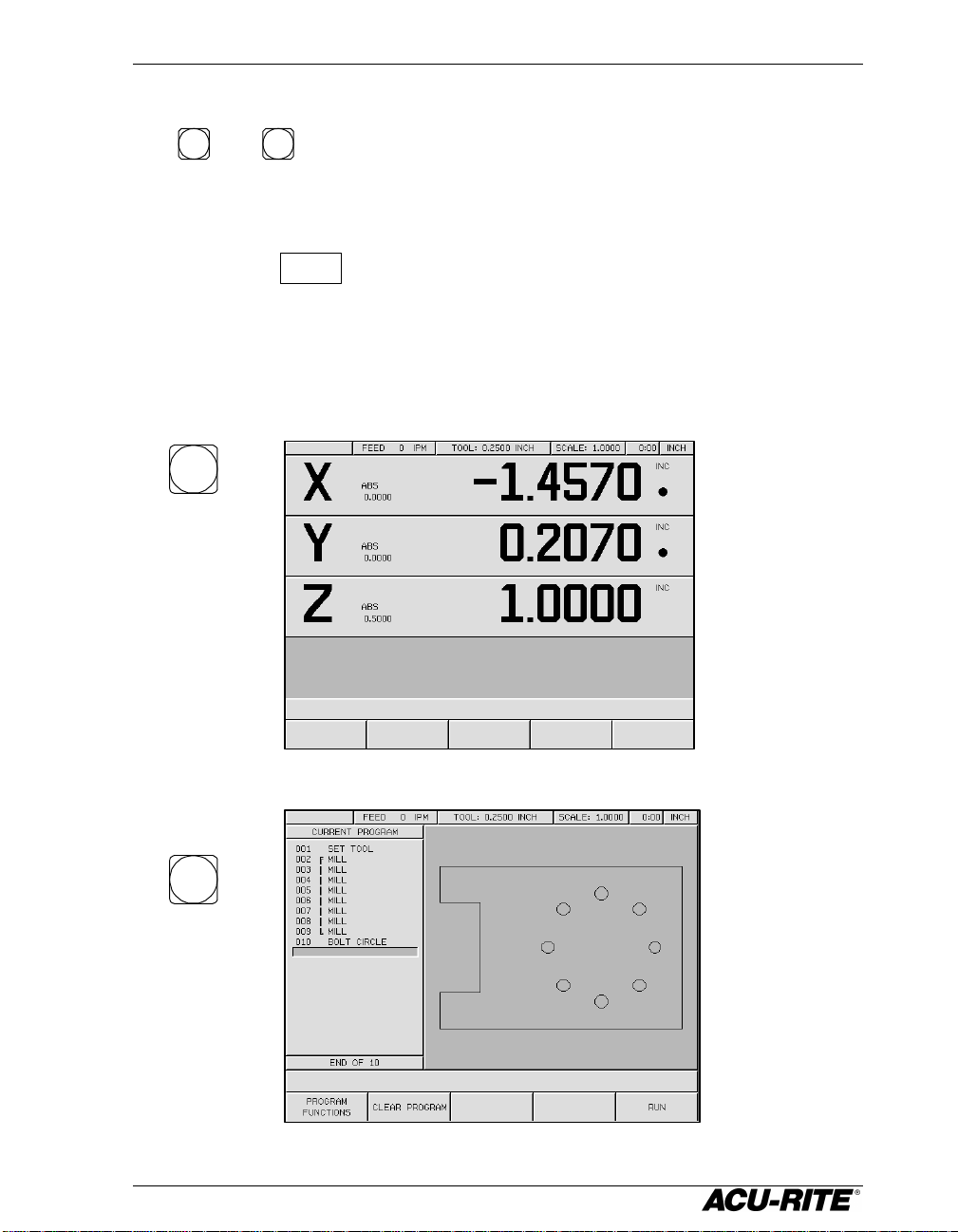
Readout and Program Displays
The
DRO
and
PGM
keys switch between the digital readout (DRO) and program
(PGM) display.
In the DRO display, all standard readout operations are available. The display
can show up to four axis positions simultaneously. If you use more than
four, press the
OTHER AXES
softkey to view the other axes. Softkeys for zeroing and
presetting these other axes will also appear.
In the PGM screen, you can create and run programs. Many of the readout
operations are still available.
DRO
PGM
5
Page 13
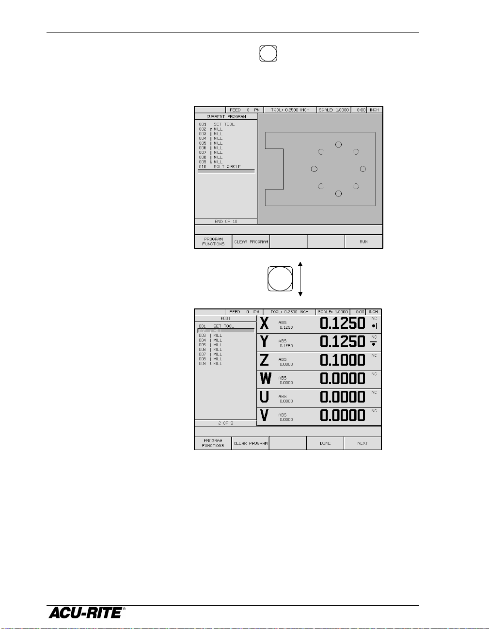
Introduction VRO 300M
When you RUN a
This is the best view for
When in the PGM screen, you can press the
VIEW
key to switch between the
part graphic and the position display. Up to six axes positions can be
displayed at the same time in this view.
programming—you can
see the results of each
step (graphically) as you
enter it.
VIEW
program, the readout
automatically switches to
this view so you can
“move to zero”.
6
Page 14

VRO 300M Introduction
Power-On Position Recovery
Position-Trac
Certain ACU-RITE encoders, such as the ENC 150, contain closely-spaced
reference marks that enable the display to show the correct position after a
power interruption. The readout will indicate when power has been lost, and
will prompt you to move each axis until a reference mark is located. By
traversing the reference marks once in each axis, you will re-establish the
display position relative to the last known zero. The most you will ever have
to move an axis is about one inch. You must move in a positive count
direction
If you use an encoder that does not have the Position-Trac feature, the
procedure for recovering your position is slightly different. Reference marks
on these encoders are about 8 inches apart. You must find a convenient
reference mark and then use the same mark every time.
1. Move near the desired reference mark.
2. Press the
3. Move slowly past the reference mark until the readout recalls
.
key.
its position. You must move in a positive direction.
7
Page 15
Readout Operations VRO 300M
Large display shows
Large display shows
Readout Operations
Clear Key
Use the
CLEAR
key to erase digits that you entered by mistake, or to take you
back if you’ve pressed an incorrect function key.
Absolute and Incremental Displays
Absolute Display
Shows the distance from your current position to absolute zero.
The drill is positioned at
1.625 ABS.Absolute Zero,
also called datum
or Workpiece
Zero
1.625
X 1.625 ABS
Incremental Display
Shows the distance from your current position to incremental zero. An
incremental zero is set when you preset a dimension, or when you zero the
incremental display.
The drill is 0.625 on
the negative side of
the incremental zero.
Absolute
zero.
1.000
-0.625
You can always see both absolute and incremental positions at the same
time.
X 1.000 ABS
INCR
ABS
1.625
X -0.625 INC
ABS
INCR
Incremental zero: the
incremental display
will read 0.000 when
the drill is here.
absolute position
incremental position
8
Page 16
VRO 300M Readout Operations
2.44
Shortcut
You don’t have to worry about
Zeroing the Displays
Absolute Zero
On many prints, dimensions are measured
from one or two surfaces of the workpiece. By
setting the readout’s absolute display to zero
at a well-chosen surface, you can enter
the part’s dimensions directly
from the print, using absolute
presets.
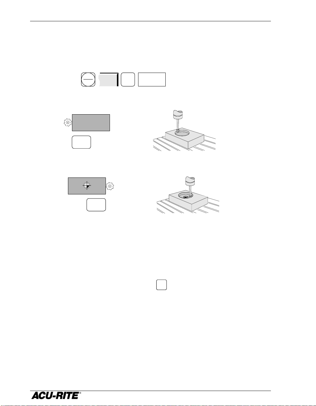
Setting Absolute Zero at the Current Position
1. Move to desired location.
Absolute zero
0.72
1.44
2. Make sure that the absolute position is displayed.
3. Zero the apropriate axis.
Setting Absolute Zero Using an Electronic Edge Finder
1. Install the edge finder into the spindle and connect it to the
ZERO
ENTER
ZERO ZERO
readout.
2. Make sure that the absolute position is displayed.
3. Press the zero key for the appropriate axis.
4. Move slowly until the edge finder touches the edge
ZERO
of the metal workpiece. The absolute position
display will automatically be set to zero at the
workpiece edge.
ABS
INCR
ABS
INCR
ABS
ABS
overtraveling because the edge
finder probe shaft is flexible. The
readout will zero on contact.
9
Page 17
Readout Operations VRO 300M
Shortcut
Setting Absolute Zero with a Tool
1. Touch the tool to the edge of the workpiece.
2. Make sure the absolute position is displayed.
3. Press the zero key for the appropriate axis.
4. Enter the position of the tool center.
+/- . 2 5
1
Setting Absolute Zero Using a Tool Offset
1. Enter the tool’s diameter.
TOOL
(Refer to page 18 for more
information about using tool
offsets.)
0.25 DIA
-0.125
ABS
INCR
ZERO
ENTER
. 2 5
ABS
RUN
2. Make sure the absolute position is displayed.
3. Identify the appropriate edge of the tool.
ABS
INCR
6
4. Touch the tool to the edge of the workpiece and zero the
appropriate axis.
ZERO
ENTER
ZERO ZERO
10
ABS
Page 18
VRO 300M Readout Operations
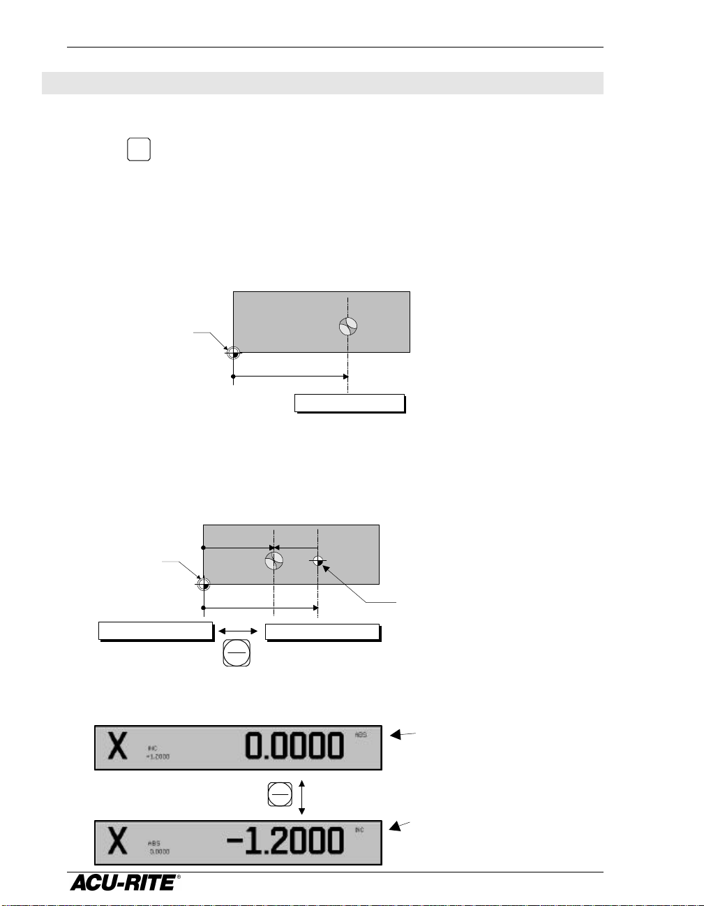
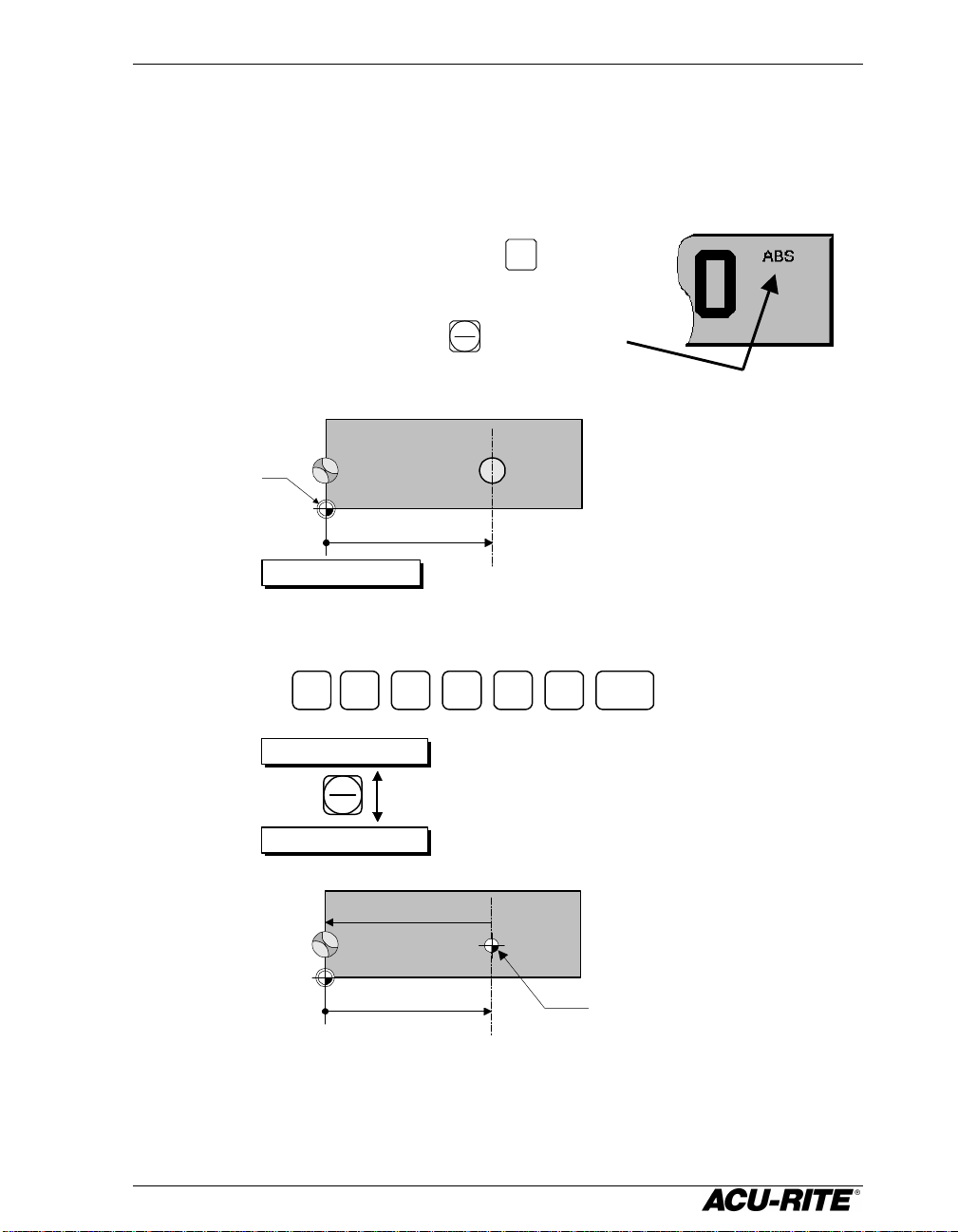
Moving the Absolute Zero
Sometimes you may need to move the absolute zero from its original position
on the workpiece to a different position.
Absolute zero
is currently
here...
1.625
X 0.0000
1. Move the tool to absolute zero.
2. Press the
ZERO
key of the appropriate axis and enter the new
tool position, from the new absolute zero.
+/- 2 5
X -1.625
6.1
-1.625
Now zero is here,
and the tool position
is -1.625
...but you
want it to
be here.
ENTER
11
Page 19
Readout Operations VRO 300M
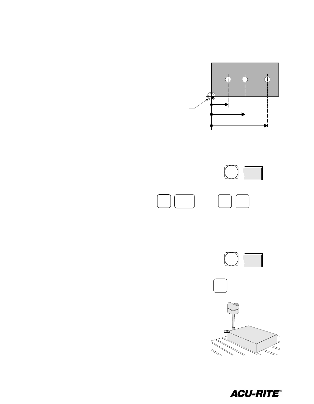
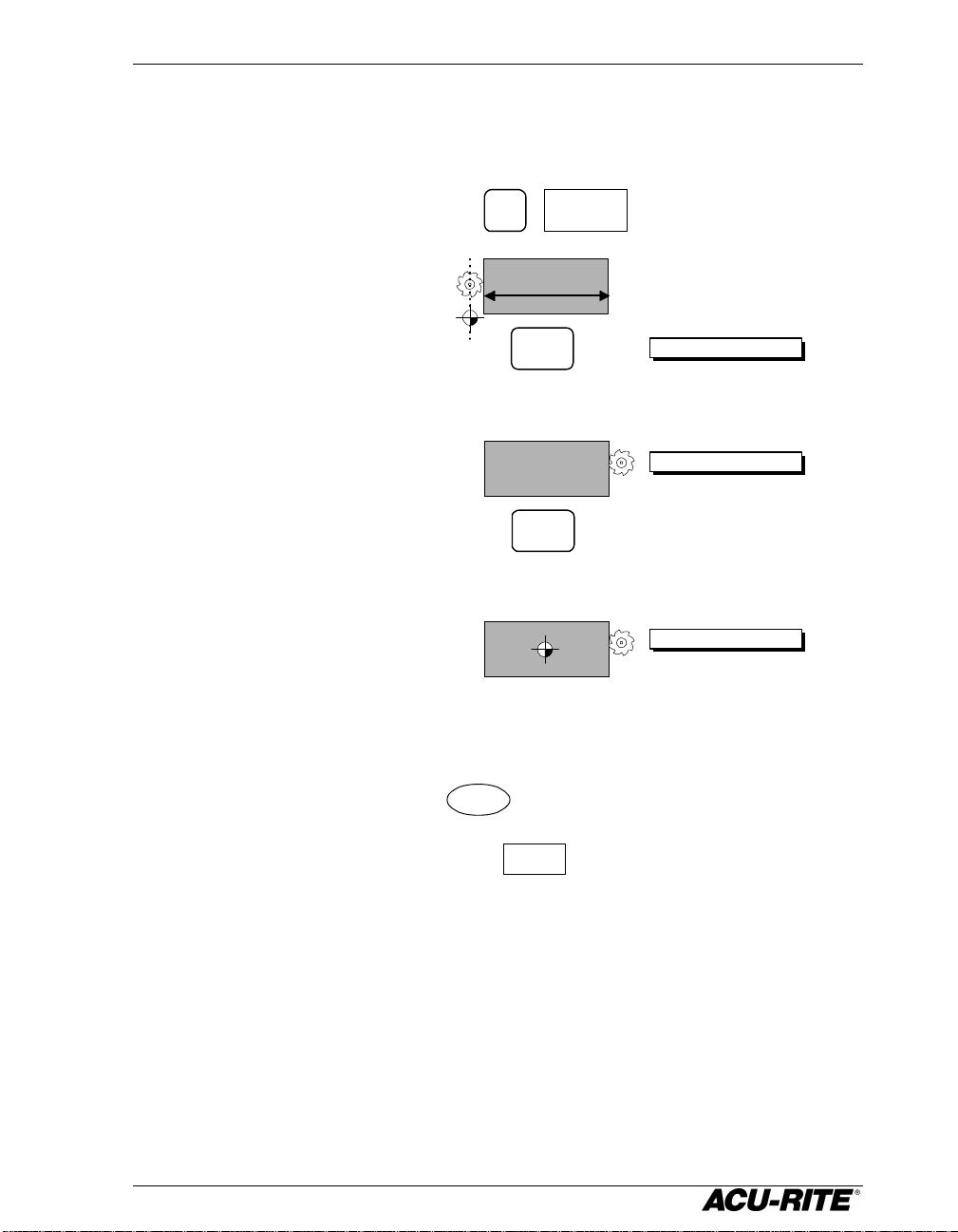
Zeroing at a Center Line
Begin setting absolute zero in the usual way and then tell the readout that
you want to use the centerline feature.
ABS
INCR
ABS
ZERO
CENTERLINE
Touch the first edge…
ENTER
…then the second edge.
ENTER
The absolute zero is placed mid-way between the two edges.
Incremental Zero
From the incremental display, press the
display to zero at the current tool position.
ZERO
key. This sets the incremental
12
Page 20
VRO 300M Readout Operations
Presetting
When you preset a dimension, the readout places an incremental zero at the
location you specify. Then the display automatically switches to the
incremental display so that you can move to zero.
Begin a preset by pressing an axis key (X for
example). The information of the previous preset will
appear. The display will show you if the preset is
absolute or incremental. Use the
between them. Enter the dimension that you want
to preset.
Absolute
zero.
1.625
X 0.000 ABS
ABS
key to toggle
INCR
The drill is positioned at
0.000 ABS.
Preset the absolute
location of the hole.
X 2 5
X -1.625 INCR
ABS
INCR
X 0.000 ABS
-1.625
1.625
6.1
ENTER
The display automatically
switches to incremental.
Now the drill is on the
negative side of the
hole.
Incremental zero: the
incremental display
will read 0.000 when
the drill is positioned
over the hole.
13
Page 21
Readout Operations VRO 300M
When you enter an incremental preset, the
Absolute and Incremental Presets
To maintain the best tolerance and to minimize the chance for errors, use
• absolute presets for absolute dimensions
• incremental presets for incremental dimensions.
When you enter an absolute preset, it does not
matter where the tool position is. The VRO 300M
calculates the desired location automatically.
0.72
Absolute
Incremental
1.44
2.44
Incremental
ABS
X
X
INCR
ABS
ABS
ABS
. 7 2
1
4
.X 4
2 . 4 4
tool must be positioned at the location you are
dimensioning from.
ABS
INCR
INC
. 5 0
INC
1 . 0
0.50
0.72
1.00
X
ABS
X
ENTER
ENTER
ENTER
7
.X 2
ENTER
ENTER
ENTER
14
Page 22
VRO 300M Readout Operations
Center-line Presets
You can set a preset at the center of a workpiece, or in the center of a hole.
CENTERLINE
X
Move to the first edge…
…then to the second edge
2.0
ENTER
ENTER
Sets an incremental
zero at the tool
location.
X 0.000 INCR
X 2.250 INCR
Calculates the center
point, and sets an
incremental zero there.
X 1.125 INCR
Presetting Using the POS Key
You can enter a preset using the
once. Refer to page 25 for information on how to complete the Position Step.
When you have completed it, press the
operation.
POS
key for as many as four axes at
RUN
softkey to execute the preset
15
Page 23

Readout Operations VRO 300M
Zero is here
Near Zero Warning
When you are moving to zero, the readout can
“warn” you when you are getting close. This
allows you to machine faster and avoid
overshooting your desired location.
You can set the near zero range in Setup.
Near zero
indicator
Near zero range:
the indicator
appears when you
are within the
range.
16
Page 24

VRO 300M Readout Operations
Tool Offsetting
If you enter the diameter of the cutting tool you are using, you don’t have to
add or subtract the tool’s radius when you enter a preset. Just select which
edge of the tool you want to compensate for, and the VRO 300M automatically
adds or subtracts the tool’s radius.
Defining the Offset Direction
The symbols on the number keys indicate the offset directions—they
represent a top view of the tool and the part edge.
Tool Back
Edge
8
Tool Left
Edge
2
Tool Front
Edge
Tool Right
654
Edge
Tool Center
2
8
4
Inside...
...and outside
46
6
2
8
Whenever the readout is displaying an absolute or incremental position, the
number keys can be used for tool offset compensation. Just press the key
corresponding to the edge of the tool whose position you want to display.
17
Page 25

Readout Operations VRO 300M
Part
Tool
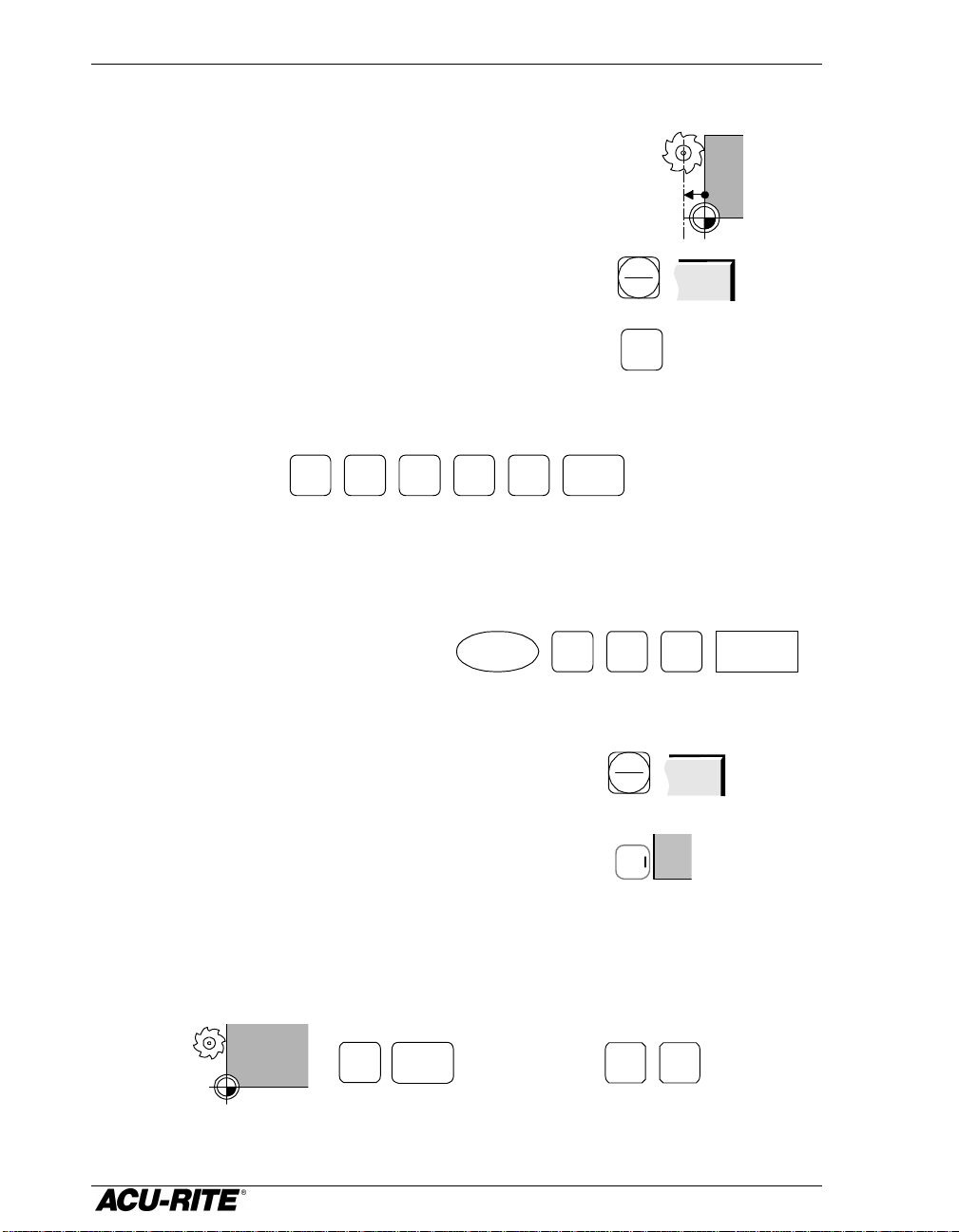
Using Tool Offsets
First enter the tool diameter.
SET TOOL
TOOL
. 5 0 0
RUN
Then select the edge you want to use for the axis you want to move. For
example, if the right edge of the tool is touching the workpiece zero, pressing
these keys will change the display as shown.
TOOL SIZE
DIA
LEN
UNIT
TOOL TYPE
0.500
INCH
6
Right edge
X 0.000 ABS
Left edge
X -0.500 ABS
4
5
Center
(Always use
this when
drilling.)
X -0.250 ABS
The readout display will always indicate how the tool is being compensated.
Left
edge
Right
edge
Front
edge
Back
edge
Center
18
Page 26

VRO 300M Program Operations
Program
Part graphic
Program Operations
A program is a list of tool changes and position presets that you can save for
later use.
Creating a Program
Press the
Name
Program
Steps
PGM
key to view the program screen.
You create a program by entering a list of the steps in the order you want to
do them. As you add to your list, each step will be drawn immediately on the
screen so you can see a picture of your part in progress.
• To create a new step, press the desired milling function key. Enter the
information describing the step into the form, and press the
USE
softkey to accept the data. This updates the program and moves down for
the next step.
• To change a step, use the arrow keys to move to the step, and press
USE
or
ENTER
. When you have made your changes, press the
USE
softkey to accept the changed step back into the program.
• To delete a step, move to the step and press the
CLEAR
key.
• To insert a step, move to where you want the new step to go and press the
desired milling function key. The new step is inserted and the following
steps will move down.
If you decide not to use a step that you have already selected, press the
CANCEL
softkey.
19
Page 27

Program Operations VRO 300M
Saving and Loading Your Programs
Programs can be saved in the VRO 300M. If a program is saved, it is safe from
power loss. Saving and other program functions are found by pressing the
PROGRAM
FUNCTIONS
softkey.
PROGRAM
FUNCTIONS
To save a program, press
or use the
ALPHABET
softkey to select alphabetic characters. You can use up to
8 characters in the name. When you have named the program, press
SAVE
CLEAR
PROGRAM
SAVE DELETE CANCELLOAD
SAVE
RUN
. Name the program using the numeric keys,
ENTER
.
ENTER
LOAD
softkey. Use the arrow keys
.
PROGRAM
CLEAR
To run or edit a saved program, press the
to select the program name, and press
To clear a program which is currently on the screen, press the
softkey. This does not delete any programs which have been saved; it simply
clears the program from the display.
To delete a program which has been saved, press the
the program name, and press
DELETE
again.
DELETE
softkey, move to
or
The VRO 300M will ask you for confirmation
before you clear or delete a program.
20
Page 28

VRO 300M Program Operations
Alphabet Entry
When you need to enter alphabetic characters, press the
ALPHABET
the alphabet box appears.
ALPHABET
A B C
D E F G H
I J K L M
N O P Q R
S T U V W
X Y Z
Use the softkeys to move around in the alphabet, and the
ENTER
key to select
a letter.
UP ALPHABET DOWN RIGHTLEFT
You can mix alphabet characters with numerals from the keypad.
softkey and
Press the
ALPHABET
softkey again to clear the alphabet box.
21
Page 29

Program Operations VRO 300M
Running a Program
To run a program, move to the first step and press the
must now execute the step and, when you are done, press the
RUN
softkey. You
NEXT
softkey
to run the next step.
When you run a program, the part view graphic is automatically replaced by
the position display so you can move to zero as required.
You can run a program starting from any step; just move to the step you
want to start with and press
RUN
. Remember that milling function steps
are normally preceded by a Tool step that is required to calculate the correct
tool offsets.
Tool Steps
If the step is a Tool step, the new tool offsets are used and the new tool
description is shown in the status bar. Check the tool you are using, and
change it if necessary.
Positioning Steps
If the step is a positioning step (such as Mill or Bolt Circle), the programmed
position is preset into the axis displays. The axis display is switched to
incremental. You can now move to zero in each axis.
22
Page 30

VRO 300M Program Operations
Programming a Tool Offset
When you are entering a program, you don’t have to worry about the actual
tool path. Because of the tool radius compensation capability built into the
VRO 300M, you program only the actual part dimensions. When you program
a cutting step, use the TOOL COMP field to tell the readout which side of the
cut you want the tool to be on.
Picture yourself standing behind the tool as it is moving. If the tool is on the
left of the workpiece, use “left” offset. If the tool is to the right of the
workpiece, use “right” offset.
By using left and right offsets, you
can program the dimensions of the
part as found on the blueprint. The
readout will take care of all cutter
radius compensation. You do not
have to program the tool path.
If you use “center” offset, the
programmed dimensions are for the center of the tool.
Left offset
Right offset
23
Page 31

Program Operations VRO 300M
Tool Steps
Put this step in your program whenever you
need to use a different tool. Press the
key to bring up the Set Tool form.
TOOL SIZE—enter the diameter of the tool and,
optionally, its length offset.
TOOL
TOOL SIZE
DIA
LEN
UNITS
UNITS—use the softkeys to select inches or
millimeters.
TOOL TYPE—use the
TOOL
softkey to open the
TYPES
TOOL TYPE
list of tool types. If you use the Tool Type feature, the readout can let you
know what kind of tool you had in mind when you wrote the program.
SET TOOL
0.2500
0.5210
INCH
FL END ML
If you wish, press the
TOOL
softkey to select a tool directly from the Tool
LIBRARY
Library. Use the arrow keys to select the tool, and the
selected tool into the Tool Step.
ENTER
key to put the
24
Page 32

VRO 300M Program Operations
This becomes Step 002. It will be
This becomes Step 003. Notice that the X
We’ll use 2 Position Steps to drill
Hole drilled at
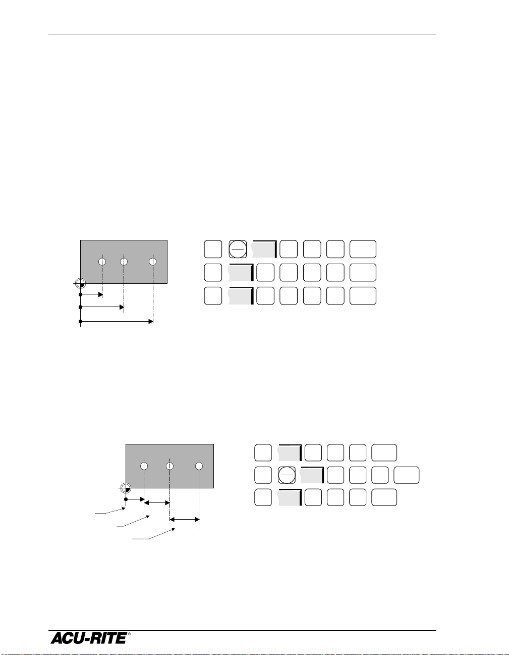
Position Steps
This step lets you program a positioning move. You can preset up to four axes
at once. The dimension in each axis can be absolute or incremental.
POINT—press an axis key (X for example) to
specify which direction you wish to move.
Enter the dimension. If the dimension is
incremental, press the
ABS
key and enter the
INCR
number of the step you want to reference. The
reference step must precede the current step in
the program.
Use the arrow keys or the
ENTER
key to move
from one axis to another.
Example
1.5
1.0
Absolute Zero
1.20
3.00
Incremental Zero,
position step 002
POSITION003
POINT
INCR
X
Y
-1.200
1.000
002
ABS
these holes. This example assumes
that Step 001 is a Tool Step.
POS
.3 0
ENTER
1.5
3.00
Incremental Zero,
position step 003
1.0
-1.20
Position Step
002
YX1 . 5
USE
the reference step for Step 003.
POS
Y
+/-
1 . 0
.1 2
USE
ABS
INCR
2X
dimension is measured incrementally from
Step 002.
25
ENTER
Page 33

Program Operations VRO 300M
The readout will automatically
Mill Steps
This function lets you mill a straight line. The
readout will first preset the location of the
starting point of the line, then the end position of
the line.
FROM—enter the start point of the line.
DEPTH—this may be left blank.
TO—use an axis key to select either a horizontal
or vertical movement, then enter the end point of
the line.
TOOL COMP—use the softkeys to select left, center,
or right radius compensation.
When you program a continuous contour of
milling steps, the readout will compensate for
tool offset at the start and end of each cut. For
mill steps to be continuous, they must:
• have the same depth,
• be cut with the same tool,
• be cut on the same side (left, right, or center),
FROM
X
Y
DEPTH
Z
TO
X
TOOL COMP
CENTER
MILL
ABS
ABS
ABS
ABS
• “touch”—the end of one must be the same as the start of the next.
When you follow one Mill Step with another, the readout assumes that you
want them to be connected. It automatically fills in the FROM point, DEPTH, and
TOOL COMP. All you have to do is fill in the TO point and press
detect continuous contours,
and will mark the program
listing so you can see the Mill
Steps that make up the
contour.
CURRENT PROGRAM
001 SET TOOL
002 MILL
003 MILL
004 MILL
26
USE
.
Page 34

VRO 300M Program Operations
Bolt Circles
You can program full or partial circle patterns.
HOLES—enter the number of holes.
CENTER—enter the center of the pattern.
RADIUS—enter the radius of the pattern.
ANGLES—you can rotate the first hole of the
pattern by filling in the start angle. You can
also do partial circles: the number of holes
you entered will be spaced evenly between the
angles. Leave the END ANGLE blank if you want
a full circle.
X
BOLT CIRCLE
HOLES
CENTER
X
Y
RADIUS
ANGLES
0.000 START
DEPTH
Z
ABS
ABS
END
ABS
Start
Angle
X
Full Circle
End
Angle
Partial Circle
27
Rotated Circle
Start
Angle
X
Page 35

Program Operations VRO 300M
Hole Frame and Hole Array
The frame and the array hole patterns require
the same information. Arrays have holes in the
middle of the rectangular pattern, while frames
have holes only on the outside edge of the
rectangle.
HOLES—enter the number of holes in each
direction.
CORNER—enter the center of the lower left hole.
SPACING—enter the distance between hole centers.
ANGLE—you can tilt the hole pattern; measured
from the 3 o’clock position.
Frame
HOLES
X
Y
CORNER
X
Y
SPACING
X
Y
ANGLE
DEPTH
Z
Array
HOLE ARRAY
ABS
ABS
0.0000
ABS
Corner
Corner
Corner
ANGLE
Tilted
28
Page 36

VRO 300M Program Operations
Row of Holes
This step makes it easy to enter a row of equally
spaced holes.
HOLES—enter the number of holes.
FROM—enter the center of the first hole.
SPACING—enter the distance between hole centers.
ANGLE—measured from the 3 o’clock position.
ANGLE
ROW OF HOLES
HOLES
FROM
X
Y
SPACING
0.750
ANGLE
DEPTH
Z
9
ABS
ABS
0.000
ABS
29
Page 37

Program Operations VRO 300M
Rectangular Frame
A frame step lets you mill a rectangular shape.
The frame is defined by its lower left corner and
its size. You can use this step to specify the edge
of a pocket.
CORNER—enter the lower left corner location.
SIZE—enter the width and height of the rectangle.
DEPTH—enter the depth.
DIRECTION—decide between conventional milling
and climb milling using the
CW
and
CCW
softkeys.
FRAME TYPE—select the tool offset directions using
the softkeys. You can mill a pocket if you use the
inside offset.
RECT FRAME
CORNER
X
Y
SIZE
X
Y
DEPTH
Z
DIRECTION
CW
FRAME TYPE
INSIDE
ABS
ABS
ABS
SIZE Y
DEPTH
SIZE Y
SIZE X
DEPTH
OUTSIDE FRAME INSIDE FRAME CENTER FRAME
SIZE X
SIZE Y
SIZE X
30
Page 38

VRO 300M Program Operations
Repeats
Using this step, you can repeat whole parts, or sections of parts, horizontally,
vertically, or both.
STEP RANGE—enter the numbers of the first and last
steps that you want to repeat.
OFFSET—enter the offset in either X or Y, or both
STEP RANGE
FIRST
LAST
REPEAT
directions. The offset is the distance between
repeats.
REPEAT—enter the number of repeats you want in
addition to the original.
Example:
001
MILL
002
MILL
003
MILL
004
MILL
005
MILL
006
MILL
OFFSET
X
Y
REPEAT
MORE
To repeat the above program once, 6 inches to the right, fill in the Repeat
form like this:
REPEAT
STEP RANGE
FIRST
LAST
001
006
Original Repeat
OFFSET
X
Y
REPEAT
6.00
6.00
MORE1
Because the Repeat form hides the program list, you can use the
softkey to toggle between the form and the list of steps.
31
SHOW STEPS
Page 39

Program Operations VRO 300M
Mirror Images
You can make a mirror image of any section of you program using this step.
STEP RANGE—enter the numbers of the first and
last steps that you want to mirror.
MIRROR ABOUT—enter the position of the “mirror
line”, called the axis of reflection. Use the
X
or Y key to choose the direction, and enter
the location of the axis.
STEP RANGE
FIRST
LAST
MIRROR ABOUT
MIRROR
ABSX
Example:
001
002
003
004
005
006
MILL
MILL
MILL
MILL
MILL
MILL
To mirror the above program about a vertical line 1 inch on the negative side
of absolute zero, fill in the Mirror form like this:
MIRROR
STEP RANGE
FIRST
LAST
001
006
Axis of
reflection
OriginalLeft-hand part
MIRROR ABOUT
ABSX -1.00
1.00
Because the Mirror form hides the program list, you can use the
softkey to toggle between the form and the list of steps.
32
SHOW STEPS
Page 40

VRO 300M Program Operations
Explode
Any repetitive type of step causes the VRO 300M to create copies of one or
more simpler steps. For example, the Repeat step below creates 2 copies of
the 6-line contour, yet it takes only one step. Similarly, a single Bolt Circle
step causes the readout to create several holes.
001
MILL
002
MILL
003
MILL
004
MILL
005
MILL
006
MILL
007
REPEAT (001-006)
Repetitive type steps include Repeat, Mirror, Row of Holes, Hole Frame, Hole
Array, and Bolt Circle.
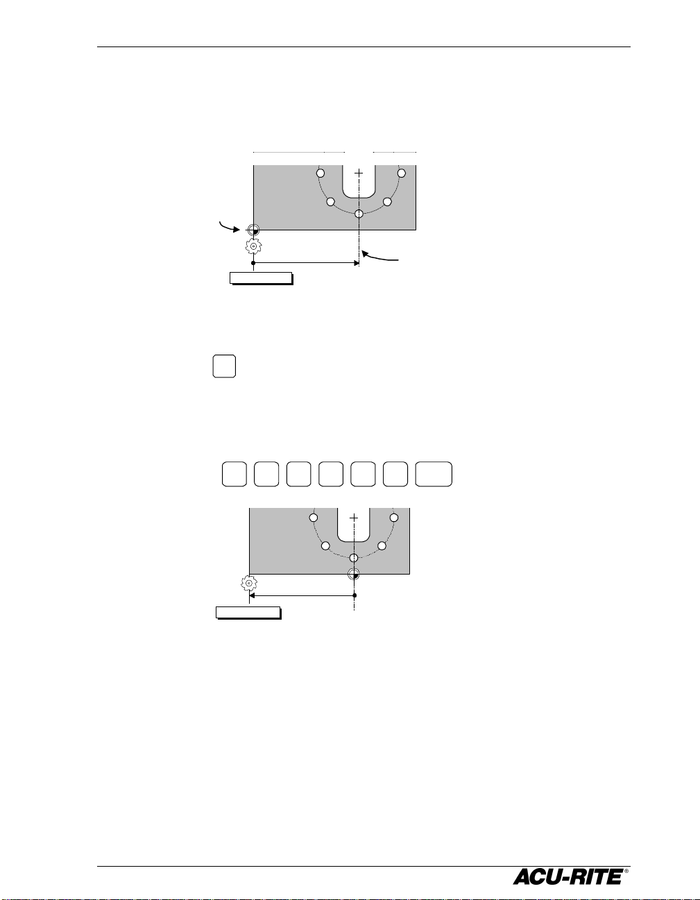
The Explode function will take one of these repetitive type steps and replace it
with the individual steps. This is useful when you need to change or
eliminate one of the individual steps.
For example, to program an eight-hole bolt circle without the third hole:
1. Program the eight-hole bolt circle.
2. Highlight the Bolt Circle step.
3. Press
MORE
EXPLODE
. The Bolt Circle step is removed and eight
Position steps are inserted in its place.
4. Move to the third hole and press the
002
002 BOLT CIRCLE
Explode step 002 to get 8
Position steps. Highlight
the third hole and press
the key.
CLEAR
003
004
005
006
007
008
009
POSITION
POSITION
POSITION
POSITION
POSITION
POSITION
POSITION
POSITION
CLEAR
key.
002
003
004
005
006
007
008
POSITION
POSITION
POSITION
POSITION
POSITION
POSITION
POSITION
33
Page 41

Program Operations VRO 300M
Teaching a Position
To teach a position to the readout as you are making a part, select a step as
you normally would. In any field where a position is needed, instead of
entering numerical position values, machine to the position that you want to
enter, then use the
position values are used.
Example
The Position step below needs to have the Y-axis entered.
TEACH POSITION
softkey to enter the position value. Only absolute
Press the
TEACH POSITION
softkey and the
absolute position from the Y display is
automatically placed in the Y field.
34
Page 42

VRO 300M Calculator
Other Features
Calculator
The four-function calculator keys,
+ - x
are available when you
,
are in any numeric data entry field. Just use these keys as you would any
calculator.
The keys will act on a number that is already in the field. For example, if you
move to a field which already has a value of 3.125, and you want to double it,
just press
x
ENTER
2
to get 6.250.
When you have more than one calculation in a field, the calculator will
perform multiplication and division before it does addition and subtraction.
This means that you can enter
+3 1 8
to get three and one-
eighth (the 1 ÷ 8 is done before the 3 is added).
The VRO 300M can calculate trig functions, tilt angles, and rotational speeds.
Press the
CALC
key, and the following softkeys appear.
TRIG TILT RPM CANCEL USE
Trig Functions
When you’re entering data for a position function, you may need to calculate
dimensions using the trig calculator. Press the
following function softkeys are shown.
TRIG
softkey, and the
SHIFT
SQR ROOT
SQR
SIN
ARC SIN
COS
ARC COS
TAN
ARC TAN
Most of the calculator softkeys are divided in half. At first, the top half is
“active”, while the bottom half is “inactive”. Press the
SHIFT
softkey and the
bottom half of the calculator options becomes active.
SHIFT
SQR ROOT
SQR
SIN
ARC SIN
COS
ARC COS
TAN
ARC TAN
Typically, a result is calculated by entering a number and then selecting the
appropriate math function. For example, to enter a number whose value is
the square root of 2, press
CALC
, 2,
TRIG
(the square root of 2) will be displayed. Press
, and
SQR ROOT
USE
. The value 1.4142
to accept the result.
35
Page 43

Calculator VRO 300M
Trig functions are calculated by entering the angle first and then the
appropriate trig function. For example, enter
3
0
, then select the
SIN
softkey. A value of 0.5000 (sin 30º) will be displayed.
Tilt Angle Calculator
You can calculate tilt or rotation anlges either by entering dimensions from a
print, or by touching a tilted workpiece with a tool or indicator.
TILT AXES—use the axis keys on the keypad to
change the axes if needed.
FIRST POINT—either enter a point from the print, or
touch the tool to one point and press the
TEACH
POSITION
softkey, once for each axis.
SECOND POINT—enter a second point on the
workpiece.
TILT ANGLE—is automatically calculated.
TEACH
POSITION
TILT ANGLE CALCULATOR
TILT AXES
FIRST AXIS
SECOND AXIS
FIRST POINT
X
Y
SECOND POINT
X
Y
TILT ANGLE
X
Y
0.5000
0.0000
0.7500
3.2500
85.6014
4.3987
X
Y
ABS
ABS
ABS
ABS
DEG
DEG
Y
Y-axis angle
TEACH
POSITION
X-axis angle
X
36
Page 44

VRO 300M Calculator
RPM Calculator
This feature lets you calculate a rotational speed
based on a diameter and the desired surface
speed.
DIAMETER—enter the diameter of the tool. You can
change to metric with the MM key.
SURFACE SPEED—enter the desired surface speed.
You can change between feet/minute and
meters/minute using the softkeys. For
convenience, the
SURFACE
SPEED TABLE
softkey brings up a
table of surface speeds for various materials.
RPM—is calculated automatically.
RPM CALCULATOR
DIAMETER
2.000
SURFACE SPEED
150
RPM
INCH
FT/MIN
286
37
Page 45

Printing VRO 300M
Some setup
Printing
If you have a printer connected to the VRO 300M, you can have the readout
print various pieces of information. Softkeys are available whenever there is
something that you can print.
POSITION—when the axis positions are displayed, press the
print the positions.
Information about the tool in use is
printed before the position. The absolute
and incremental positions for each
displayed axis is printed with the units of
measure.
TOOL: DIAMETER = 0.1250
INCH
LENGTH = 1.2500
INCH
X:+ Y:o
X ABS 2.9710
Tool offset symbols indicate whether the
printed position is on the positive (+) or
INCH
INC 2.9710
negative (-) edge of the tool, or at the
tool’s center (o).
PROGRAM—when the program list is visible, you can press
PRINT
the
softkey to print out each step of the program.
PROGRAM
PROGRAM NAME: PART100
information, such
as scale factor,
prints here.
DIMENSION UNITS = INCH
PRINT
POSITION
PROGRAM
FUNCTIONS
softkey to
then
,
001 SET TOOL
NUMBER = 2
X = 1.2500
INCH
Y = 0.5440
INCH
002 POSITION
X = 0.0000
ABS
Y = -0.5000
ABS
38
Page 46

VRO 300M Printing
TOOL LIBRARY—when you are looking at the tool library, press the
to print a copy of it.
TOOL LIBRARY
NUMBER DIAMETER LENGTH
UNITS TYPE
00 0.5020 / 0.0021
INCH EDGE FNDR
01 0.2953 / 1.3822
INCH FL END ML
SYSTEM PARAMETERS—the
PRINT SETUP
softkey is displayed in the Job Setup screen.
Both job-related and machine-related parameters are printed.
JOB SETUP PARAMETERS
DISPLAY RESOLUTION
X = 0.0005 INCH
Y = 0.0005 INCH
PRINT TOOL
LIB
softkey
39
SCALE FACTOR
1.0000
NEAR ZERO WARNING
Page 47

Remote Interface VRO 300M
Remote Interface
You can enter commands into the VRO 300M from a remote terminal or
computer if you have configured the serial port as a COMPUTER. These remote
commands are in the form of ANSI standard ASCII characters. The remote
device can request that the readout send information, such as the current
position, or the device can control the readout by simulating the pressing of
any of the readout’s hard keys or softkeys.
Requesting Information
Commands that request information from the readout begin with the
question mark character. As soon as the command is recognized, the
response data is sent, terminated by a CR character. Invalid commands are
ignored.
String Command
?* Reset
?En
?Ix
?Ax
?U Get Units
?X Get Active Axes
?T Get Current Tool
?Q Get Port Status
Set Echo Mode: echo
when a keypad
command is sent.
Get Incremental
Position
Get Absolute Position
Response
No information returned. Resets the echo mode and clears
input and output buffers.
n is equal to 0, 1, or 2. If n = 0, no echo. If n = 1, echo the
control character sent. If n = 2, echo a string describing the
key function. Refer to the “Readout Keypress” column in the
Keypad Command table on page 41for the strings.
Returns the position for the axis specified. x = 1, 2, 3, 4, 5 or
6. Examples are:
“X= -123.4567 INCH”, “Y= +123.4567 DEG”
For an undefined axis, the response is “* = ****.**** ***”. If an
error exists, the response is: “x = Error mm”.
Returns the current display units, “INCH” or “MM”.
Returns the displayable axes, for example:
“X Y Z W ** **”
“**” means the axis is not displayed.
Returns current tool information, for example:
“Current Tool: Diameter: 0.125000 INCH Length: 1.25000
INCH Tool Type: 1”
Verifies the operation of the port connected to the computer.
The responses are:
0 = No parity, data overrun, or buffer overflow errors have
occurred since the last “port status” check.
1 = One of the above errors has occurred since the last “port
status” check.
40
Page 48

VRO 300M Remote Interface
Keypad Commands
Sending one of the control characters from the following table to the readout
is equivalent to pressing the corresponding readout key.
Control
Character
Q X
W Y
E Z
R W
A ZERO X
S ZERO Y
D ZERO Z
F ZERO W
! SOFT KEY 1
@ SOFT KEY 2
# SOFT KEY 3
$ SOFT KEY 4
% SOFT KEY 5
Z TOOL
X POS
V MILL
B HOLES
N MORE
T DRO
Y PGM
U VIEW
Readout Keypress
Control
Character
0 0
1 1
2 2
3 3
4 4
5 5
6 6
7 7
8 8
9 9
. . (decimal)
_
(underscore)
[ CLEAR
] ENTER
+ +
- -
* x (multiply)
/ ÷
< UP ARROW
> DOWN ARROW
Readout Keypress
+/-
I INFO
O SET UP
G ABS/INCR
H MM
J CALC
41
Page 49

Other Features VRO 300M
Job Clock
The job clock can help you
Hours : Minutes
estimate jobs or monitor
throughput. It records to the
nearest minute. You can start,
stop, and reset the job clock
using the softkeys in Setup.
Refer to page 52.
Reference Tables
Several useful tables, including tap and drill sizes and machine cutting
speeds, are included in the VRO 300M. Press the
INFO
key, then the
softkey to see the index of topics. Move to REFERENCE TABLES and press the
key.
INDEX
ENTER
42
Page 50

VRO 300M Setup
Setup
SETUP
The
parameters are job related, meaning that they may change from job to job.
Others are machine related and should be set as part of the installation. The
machine-related parameters can be accessed by pressing the
and entering the access code.
key lets you change the system parameters. Some of these
INSTALLATION
SETUP
softkey
Use the
ENTER
key to select the parameter.
USE NEW
The
Use the
softkey will terminate the setup process and save the changes.
SETTINGS
CANCEL
CHANGES
keys to move from one parameter to the next, and the
softkey to cancel the changes.
JOB SETUP
TOOL LIBRARY
DISPLAY RESOLUTION
SCALE FACTOR
NEAR ZERO WARNING
ERROR COMPENSATION
JOB CLOCK
FEED UNITS
REMOTE SWITCH
INSTALLATION SETUP
DISPLAY CONFIGURATION
ENCODER SETUP
SERIAL PORT
PARALLEL PORT
PROTECTION
GRAPH ORIENTATION
DIAGNOSTICS
43
Page 51

Setup VRO 300M
Job Setup
Tool Library
A list of tools is available to you for convenient selection during programming
and/or operation of the VRO 300M. There are 100 “slots” in the Tool Library.
You can organize tools any way you wish.
TOOL LIBRARY (DIAMETER / LENGTH)
00 0.2000 / 0.000 INCH EDGE FNDR
01 0.2000 / 1.205 INCH FL END ML
02 0.2498 / 0.000 INCH BL END ML
03 0.1075 / 0.000 INCH BL END ML
04 0.375 / 0.000 INCH DRILL
05 1.000 / 0.000 INCH DRILL
06
07
08
09
10
11 1.000 / 0.000 INCH BROACH
12
13
7 OF 99
To add a tool to the tool library, select an unused slot and press the
key. Fill in the diameter, length, units and the type
(press the
types). Press
TOOL TYPES
softkey for the list of available
DONE
to enter the tool into the
library.
To change an existing tool, move to that tool and
press
ENTER
. Make any changes and press
DONE
.
TOOL DESCRIPTION
SIZE
DIA
LEN
UNITS
INCH
TYPE
FL END ML
The changed tool will now appear in the library.
You can sort the tool library by tool number (so you can see them in
numerical order) or by type (so you can see all your drills together) by
pressing the
SORT BY
NUMBER
slots are not shown. To see them again, press
or
SORT BY TYPE
softkeys. When you do this, the unused tool
DONE
or
CANCEL
to return to
the JOB SETUP menu, then select TOOL LIBRARY again.
44
ENTER
.3750
1.25
Page 52

VRO 300M Setup
For a scale factor that allows for 3% material shrinkage, use this formula:
.971.03
1
1
Display Resolution
The display resolution will normally be the
same as the encoder resolution. However, if the
job tolerance is coarser than the encoder
resolution (for example, the job tolerance may
be ±0.005"), you can adjust the display
resolution so you won’t be tempted to waste
time by machining to a finer resolution.
Use the
COARSER
and
FINER
softkeys to cycle
through all the possible choices. The choices
DISPLAY RESOLUTION
X AXIS
0.0005 DIA
Y AXIS
0.001
Z AXIS
0.0005
W AXIS
0.0005
available depend upon the resolutions of the
scales.
U AXIS
V AXIS
Scale Factor
The scale factor can be set to scale the workpiece up or down from the preset
or programmed size. All preset and displayed dimensions are multiplied by
this scale factor. All programmed dimensions will be multiplied by this scale
factor when the program is run. The numbers
in your program are not changed.
A scale factor of 1.000 causes the readout to
use preset or programmed dimensions exactly.
Values greater than 1 cause parts to be made
larger; values less than 1 cause parts to be
made smaller.
SCALE FACTOR
SCALE
1.0000
Example:
rScaleFacto ==
=
−
45
1.0309
Page 53

Setup VRO 300M
Near Zero Warning
Each axis has its own near zero range. You can
activate or deactivate the near zero warning
feature by pressing the
ON
and
OFF
softkeys. When the warning is activated, you
can enter the range.
The warning indicator appears in the display
just before the tool enters the range, and it
begins to move when the tool enters the range.
The indicator moves faster as it approaches
zero. Refer to page 16.
NEAR ZERO WARNING
X AXIS
0.010
Y AXIS
0.020
Z AXIS
OFF
W AXIS
OFF
U AXIS
OFF
V AXIS
OFF
46
Page 54

VRO 300M Setup
Linear Error Compensation
The VRO 300M includes a linear error compensation feature which enables you
to compensate for machine tool inaccuracies. You can have up to 99 different
compensation segments per encoder.
In order for linear error compensation to function properly, the readout needs
to be able to establish the segment boundaries in the same physical locations
each time you turn on the readout. This means that you must find the
encoder’s reference mark. Refer to page 7, “Power-On Position Recovery”.
To begin the process, select ERROR COMPENSATION from the JOB SETUP list.
Error compensation is applied to each encoder individually, so you must first
select the axis that you want to work with. You may use a display axis key
(X for example) to select the encoder, unless the encoder is coupled with
another one, or the encoder is displayed as the U or V axis. If that is the case,
enter the number of the input that the encoder is connected to.
Examples:
• X axis displays encoder 1; you may press
X
to select this encoder.
• Y axis displays encoders 2 + 3; you may press
or
1
Y
or
2
to select encoder 2, but you must press
3
to
select encoder 3.
Once you have selected the encoder, the readout displays the error
compensation table for that encoder. Initially, there is only one segment
defined, and it applies from one end of the encoder to the other.
Segment 2Segment 1 Segment 3
+ Count Direction
Machine table front view
(slightly exaggerated)
Segment
number
ENCODER 1 ERROR COMPENSATION
01 0 PPM ENCODER END - ENCODER END
Most negative
segment boundary
Compensation
factor in parts
per million
Most positive
segment boundary
The following softkeys let you begin defining the table.
ENTER
COMP
CALCULATE
COMP
ANCHOR
SEGMENT 1
DONE
47
Page 55

Setup VRO 300M
Note: If you anchor Segment 1 in a different place after you have established
Anchoring the Segments
If you anchor the beginning of the first segment at a known location on the
encoder, then the segment boundary values will be the actual physical
distances from the anchor point, as shown below.
23.4
Segment 1
anchored here
Encoder
Anchoring the segments is optional: if you don’t do it, the segment boundary
values may be meaningless to you (although they are understood by the
readout).
8.0
Segment 1 Segment 2 Segment 3
Reading Head
ENCODER 1 ERROR COMPENSATION
01 492 PPM
02 -697 PPM
03 -78 PPM
ENCODER END -- 8.00
8.00 -- 23.4
23.4 -- ENCODER END
ANCHOR
SEGMENT 1
Pressing this softkey puts the start of Segment 1 at the current
tool location. To anchor the segments correctly, move the encoder
in the negative count direction as far as it will go, then press
the compensation values, then the entire compensation table will be shifted to
the new anchor location, as shown below.
Segment 1
anchored here
Encoder
Segment 1
anchored here
Segment 1 Segment 2 Segment 3
Reading Head
Segment 1 Segment 2 Segment 3
ANCHOR
SEGMENT 1
.
48
Page 56

VRO 300M Setup
Compensation Entry Methods
You can enter the segment boundaries and compensation factors using the
keypad, or you can have the readout calculate them for you. Normally, you
would use the keypad entry method only to restore or adjust a known
compensation value.
Manual Entry
ENTER
COMP
The
FACTOR—Enter the compensation
factor in parts per million.
SEGMENT—You can change only the TO
field. Use the
boundary is at the end of the
encoder. Use the
This brings up the softkeys needed to let you enter compensation
and segment information using the keypad.
NEW
SEGMENT
NEW
softkey brings up the DEFINE SEGMENT form.
SEGMENT
ENCODER
END
CLEAR TABLE
softkey if the
POINT
softkey to
ANCHOR
SEGMENT 1
CANCEL DONE
DEFINE SEGMENT
FACTOR
PPM2
SEGMENT
FROM
TO ENCODER END
ENCODER END
enter the physical location of the
segment boundary. The current
reading head location may be entered using
The
Continue adding segments with the
DONE
softkey saves the segment information in the table.
NEW
SEGMENT
TEACH
softkey.
POSITION
softkey. You must add them in
order, from the encoder’s most negative end to its most positive end.
The
CLEAR
softkey will delete the information from the table, erasing all
TABLE
segments and compensation factors, so that the readout will not perform any
error compensation.
49
Page 57

Setup VRO 300M
Calculated Entry
CALCULATE
COMP
The
This brings up the softkeys needed to have the readout calculate
the compensation factors.
NEW
SEGMENT
NEW
SEGMENT
softkey brings up the CALCULATE SEGMENT form.
CLEAR TABLE
ANCHOR
SEGMENT 1
STANDARD—This is where you enter the actual
length of the standard.
TRAVEL—Shows the measured length of the
standard. This would normally be slightly
different from the actual length because of
machine inaccuracies.
FACTOR—This is the compensation factor
calculated by the readout.
CANCEL DONE
CALCULATE SEGMENT
STANDARD
0.0000
TRAVEL
0.0000
FACTOR
0000 PPM
50
Page 58

VRO 300M Setup
If the calculated factor is 9999 or –9999, the machine
You will need a dial indicator and a measurement standard.
1. Position the standard in the center of the segment.
2. Enter one edge of the standard.
FIRST POINT
FIRST POINT
3. Enter the other edge of the standard.
SECOND
POINT
SECOND
POINT
4. Enter the actual size of the standard, including the probe
diameter if necessary.
8.1250
Opposite sides
inaccuracy is too great and cannot be compensated.
8.0000
Same side
5. Press
DONE
to save the segment information into the table.
The readout will automatically set the segment boundaries between the
current segment and the adjacent segments.
51
Page 59

Setup VRO 300M
Job Clock
The softkeys let you start and stop the job
clock, and let you reset it to zero. The actions
do not take effect until you leave setup with the
USE NEW
softkey.
SETTINGS
Feed Rate Units
Use the
IPM
and
inches per minute and mm per minute.
MMPM
softkeys to change the feed rate units between
Remote Switch
The external switch (pendant or footswitch)
can be enabled to perform any or all of the
following functions:
• PRINT—print the current position. Enable
key.
YES
key, disable with the
with the
NO
JOB CLOCK
ELAPSED TIME
RUNNING
REMOTE SWITCH
PRINT
ZERO
NEXT
1:38
NO
XYZ
NO
• ZERO —zero one or more axes. Use the axis
keys (X for example) to specify which axes will zero when the switch is
pressed.
• NEXT—run the next program step. The
YES
and
NO
keys enable or
disable this function.
52
Page 60

VRO 300M Setup
Installation Setup
Display Configuration
Individual encoders are connected to the VRO 300M at inputs numbered 1
through 6. The assignment of each encoder to an axis display (X, Y, or Z for
example) is done by completing this form.
Each axis display can be configured in one of the
following ways.
Unused—press the
OFF
softkey to delete the
axis from the DRO display.
Single Encoder—use the numeric keypad to enter
the encoder input number.
Coupled Encoders—you can couple two encoders
together using the +, -, or keys:
1 2
+
will display the sum of
encoders 1 and 2.
1 2
-
will display the difference
DISPLAY CONFIGURATION
X DISPLAY
1
Y DISPLAY
2
Z DISPLAY
3
W DISPLAY
3
U DISPLAY
2+3
V DISPLAY
OFF
between encoders 1 and 2.
1 2
will display the average of encoders 1 and 2.
You can display the same encoder in more than one axis.
In the above example, the X, Y, and Z displays show encoders 1, 2, and 3
respectively. The W-axis display will also show encoder 3, and the U-axis
display couples the movements of encoders 2 and 3 together. The V display
will not appear.
53
Page 61

Setup VRO 300M
Encoder Setup
You must tell the readout something about the encoders. Select ENCODER
SETUP from the Installation Setup list and enter the encoder number (the
number is defined by the input connector number on the back panel of the
readout).
The encoder number you selected is
shown at the top of the form.
RESOLUTION—first use the softkeys to select
between linear and angular movement.
ENCODER 1 SETUP
RESOLUTION
10.0000 UM
DIRECTION
POSITIVE
Linear—move the corresponding machine axis
in a positive direction until the readout senses
and displays the resolution. You won’t have to
move more than two inches. For encoders
without Position-Trac, you need to enter the
resolution in microns (µm) directly.
Angular—For an encoder used to measure angular position, enter the number
of counts per revolution.
DIRECTION—you can change the count direction with the
POSITIVE
and
NEGATIVE
softkeys.
54
Page 62

VRO 300M Setup
Serial Port
You can configure the serial port to connect to a printer or to a computer.
Check the specifications for your printer or computer to determine how to
complete the following information. For most
items, softkeys let you select values.
FUNCTION—configure to connect to a printer or to
a computer. Press
OFF
to disable the serial
port.
OUTPUT TAIL—enter the number of blank lines (CR
character), from 0 to 9, that you want to print
after the information is sent out.
LF AFTER CR—press
YES
if you want to output
a line feed character after the carriage return
(end of line).
SERIAL PORT
PORT CONFIGURATION
FUNCTION
OUTPUT TAIL
LF AFTER CR NO
PORT PROTOCOL
BAUD
PARITY
DATA BITS 8
STOP BITS 1
PRINTER
1200
NONE
0
BAUD—press the
LOWER
and
HIGHER
keys to
move through the available transmission
speeds (baud rate).
PARITY—select none, even, or odd.
DATA BITS—use the softkeys to select 7 or 8 bit word length.
STOP BITS—use the softkeys to select 1 or 2 stop bits.
55
Page 63

Setup VRO 300M
Parallel Port
Most printers connect to the parallel port. You can experiment with these
settings to format the printed output.
FUNCTION—select
PRINTER
to enable it for printing.
OFF
to disable the port or
OUTPUT TAIL—enter the number (0 to 9) of blank
lines after each printed output.
LF AFTER CR—select to send a line feed character
after the CR (end of line); some printers need
this.
Protection
PARALLEL PORT
PORT CONFIGURATION
FUNCTION
OUTPUT TAIL
LF AFTER CR NO
PRINTER
0
You have the ability to prevent changes to part
programs and to the tool library without first
PROTECTION
PROGRAM
entering into the INSTALLATON SETUP and
removing the protection.
TOOL LIBRARY
With program protection set to YES, programs
cannot be changed or saved. This prevents an
inexperienced machine operator from making
scrap parts by mistakenly changing or deleting
a step.
If you protect the tool library, it can’t be mistakenly changed either.
56
NO
YES
Page 64

VRO 300M Setup
Factory
Graph Orientation
In order for the VRO 300M to draw a graphic representation of parts as you
program them, you need to specify which machine axes correspond to the
plane of the “drawing”.
Use the axis keys (
directions.
x
for example) to select horizontal, vertical, and depth
GRAPH ORIENTATION
HORIZONTAL
VERTICAL
DEPTH
settings
57
X
Y
Z
Page 65

Installation VRO 300M
IMPORTANT
Installation
Before installing the VRO 300M readout, record the serial
number on the warranty card and return it to ACU-RITE
INCORPORATED. The serial number label is located on the
back of the readout.
Selecting A Location
Selecting a location for the readout is an important consideration for proper
installation. Keep the following points in mind when selecting a safe and
convenient location:
• The readout should be within reach of the operator for easy access to the
keypad and other controls.
• The readout should be approximately at eye level.
• Avoid moving components or tools and minimize coolant splash or spray.
• The operating environment must be within the temperature range of 0° to
40°C (32° to 104°F) with a non-condensing relative humidity of 25% to
85%.
Proper Mounting
ACU-RITE has developed special mounting kits for the readout which address
the most common mounting requirements. Mounting kits include:
• Column and base machine mountings
• Hardware and mounting instructions
These kits are available from your factory authorized ACU-RITE Distributor or
OEM/OEI.
If you fabricate a support device for the readout, it should be large enough
and strong enough to accommodate the readout. It must also be stiff enough
to minimize any vibration induced by machinery on the shop floor.
58
Page 66

VRO 300M Installation
Connecting the Encoders
Insert the connector from each encoder into the mating connector on the
back of the readout. Fasten it with a small screwdriver.
Provide enough slack in the encoder cables to allow for full travel of all
machine axes. Check that machine movements will not pinch the cables.
Use the cable tie-down hardware kits supplied with the encoders to fasten the
cables neatly to the machine.
Encoder inputs are assigned to specific axis displays through software. Note
which encoder is connected to each input, and refer to page 53 for display
configuration instructions.
Connecting a Ground Wire
Connect a ground wire from the terminal on the back of the readout to the
machine. The machine should also be connected to a solid earth ground. If
not, be sure that the readout is.
Checking Voltage and Connecting Power
Check that the voltage available at the power source is within specification
before connecting it to the readout. Refer to page 60.
Connect the readout to the power source using the power cord supplied.
!
CAUTION
Connecting the readout to a power source outside of the
acceptable range may damage the readout, the encoders, or
both.
59
Page 67

Readout Specifications VRO 300M
Readout Specifications
Characteristic Specification
Operating conditions
0° to 40°C (32° to 104°F)
25% to 85% relative humidity (non-condensing)
Storage conditions
Input requirements
Voltage:
Frequency:
Current:
Fuse
Encoder input
Control Function
Interface (CFI)
Edge finder input
Touch probe input
Ext. video output
Pendant input
-40° to 60°C (-40° to 140°F)
25% to 95% relative humidity (non-condensing)
95 – 264VAC single phase
47-63 Hz
350ma @115V, 200ma @230V
¾ A, 250V, 3AG, Slo-blo
Position signals: channels A & B
TTL square wave signal in quadrature
(90° nominal phase relationship)
Maximum input rate: 50 KHz
Reference signal: TTL square wave
Compatible with ACU-RITE CFI box
Compatible with ACU-RITE electronic edge finder
Compatible with Heidenhain touch probe
VGA 640 x 480 pixels
Compatible with ACU-RITE remote switch
Parallel port
Serial port
Size
Weight
Mounting
FCC compliance
IEEE 1284-A for standard PC printer
EIA/TIA-232E, V.28, RS-232C compatible
8.375”H x 15.25”W x 10”D
17 lbs.
Bottom: two ¼ -20 threaded inserts
Class A
60
Page 68

VRO 300M Troubleshooting
NOTICE
Troubleshooting
This section is intended to provide you with some basic troubleshooting
assistance with your readout system. If you cannot correct the problem after
following these instructions, contact your authorized ACU-RITE distributor or
OEM/OEI for repair or replacement procedures.
No Operation
If you turn power off, you must wait at least 5 seconds before
turning it back on, or the readout may not power up. This is
because the power supply, in order to withstand brief power
outages and brownouts, requires several seconds to reset
itself.
If the readout display will not operate, check the following conditions:
• Check AC power source. If the readout cannot be powered up, confirm
that line voltage is present at the source and that the line voltage meets
the required specifications.
• Check power cord. Remove the power cord at the electrical input module
on the back of the readout. Determine if line voltage is present at this end
of the cord.
61
Page 69

Troubleshooting VRO 300M
• Check fuse. With the power cord removed, use a thin straight-blade
screwdriver to remove the cover of the electrical input module. Slide out
the fuse holder and check the fuse. If necessary, replace it. Replace the
input module cover by snapping it back into place, and reconnect the
power cord.
Opening
slot
!
CAUTION
Replace fuses only with the specified type. Using incorrect fuses
can present a safety hazard. The readout may also be
permanently damaged. Refer to the Readout Specification chart
on page 60 for the correct fuse.
Incorrect Operation
If system positioning does not seem to be repeatable, the problem could be
with the machine tool or with the readout system.
• Check the machine tool. Check that the table is not locked. Ensure that
the knee, ram, head bolts, turret-to-column bolts, and head-to-knuckle
bolts are properly secured. Check the gib adjustments. Tram the head.
Check spindle run-out.
• Check linear encoders. Check each encoder and reading head for proper
installation. Ensure that the mounting brackets are secure.
62
Page 70

VRO 300M Troubleshooting
If the system seems to be displaying incorrect positions, check the following
items.
• Verify presets. Make sure the numbers that you entered are correct.
• Verify tool. Check that the correct tool is being used. Make sure the
correct tool offset has been entered. Check the tool for wear.
• Verify the scale factor. Ensure that the correct scale factor is being used.
• Verify linear error compensation. Make sure that the factors used for
linear error compensation are correct.
Errors
The readout includes built-in test and error-checking circuitry. This circuitry
identifies errors that occur, and reports the problem to the operator.
Loss of power is indicated by the “Power was off” message. Loss of power
means that power to the readout has been interrupted. Since power to the
encoders has also been interrupted, position information may no longer be
accurate. Press the
information about position recovery.
CLEAR
key to clear the error message. Refer to page 7 for
Counting errors are indicated by the “Scale miscount” message, telling you in
which axis the miscount occurred. Counting errors result from distorted
electrical signals from an encoder. These signals can be a result of an encoder
malfunction, misalignment, mounting problems, or electrical interference.
Press the
CLEAR
key to clear the error message. Follow these steps to determine
if your difficulties are associated with the readout or with the encoder.
• Ensure that the linear encoder connectors are correctly seated.
• Swap linear encoder cables at the readout to see if the problem still
appears in the same display.
• If the problem remains in the same display, the readout is in error.
• If the problem follows the connection change, the linear encoder may be
in error. Refer to the Checking the Linear Encoders section of your encoder
reference manual.
Display overflow errors are indicated by a blank axis display. A numeric
overflow occurs when the intended measurement is too large for the eightdigit display. Clear the error by returning the machine table into an area
where measurements can again be displayed, setting a new preset, or zeroing
the display.
63
Page 71

ACU-RITE Readout Systems are
JAMESTOWN, NEW YORK 14701
manufactured in the USA
ACU-RITE IS AN
ISO 9001
CERTIFIED
MANUFACTURER
2002-700 EDITION A PRINTED IN USA
ACU-RITE INCORPORATED
ONE PRECISION WAY
MASON INDUSTRIAL PARK
 Loading...