

Page 1
SENC 150
REFERENCE MANUAL
Page 2

Page 3
SENC 150
Page
1 Introduction / Supplied items ........................................ 4
2 Preparing the mounting / Mounting information ........... 5
3 Encoder dimensions ..................................................... 8
4 Backup spar dimensions ............................................. 10
5 Mounting the encoder without backup spar ............... 11
5.1 Mounting the encoder via end holes .......................... 12
5.2 Mounting the encoder via center support .................. 13
6 Mounting the encoder with backup spar .................... 14
7 Mounting the reading head ......................................... 15
8 Checking the mounting .............................................. 16
9 Specifications ............................................................. 17
10 Pin-outs .................................................................... 18
11 Output signals ............................................................ 18
Table of Contents / Warnings
3
Page 4
1 Introduction / Supplied items
SENC 150
The SENC 150 precision glass scale linear encoder provides the
accuracy and reliability of an ACU-RITE
®
measuring system with
digital output. Features and options include:
Resolutions of 0.5, 1, or 5 µm.
Accuracy grades of ± 3, and ± 5 µm/1000 mm.
Vinyl or armor cables of 5, 13, and 19 ft. length.
Distance-coded reference marks.
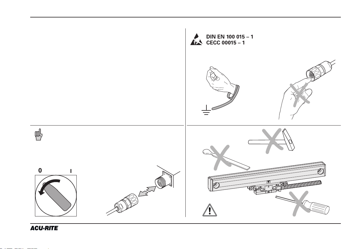
Note: Mounting and commissioning is to be conducted
by a qualified specialist under compliance with local safety
regulations. Do not engage or disengage any connections
while under power. The system must be disconnected from
power.
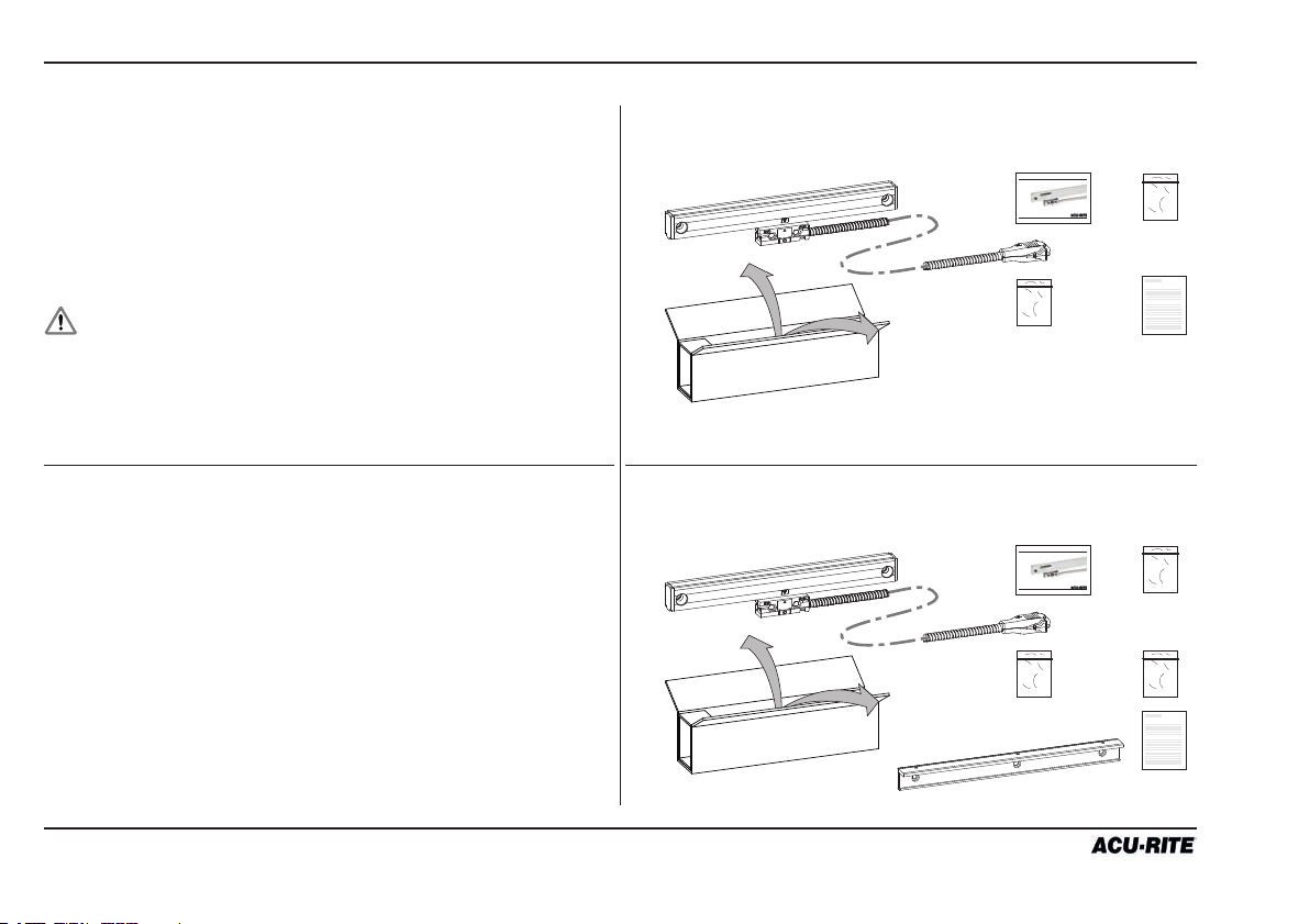
Contents key
A SENC 150 linear encoder
B Backup spar
C Reference manual
D Cable mounting hardware
E Linear encoder mounting hardware
F Backup spar mounting hardware
G Quality test certificate
Contents
ML ≤ 1550 mm (60”)
A
Contents
ML ≥ 1675 mm ( 65”)
A
SENC 150
C
E
SENC 150
C
E
D
REFERENCE MANUAL
G
D
REFERENCE MANUAL
F
G
B
4
Page 5
SENC 150
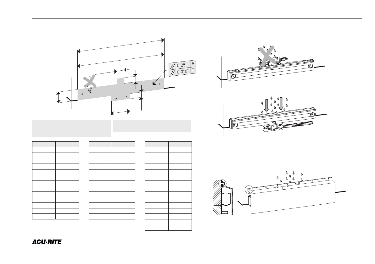
2 Preparing the mounting
Mounting surface clean and free of paint. Protect sealing lips from splash water.
*LL [mm] x 25.4 + 161.6
*LL [“] + 6.362
***L [“] ±0.35
***L [“] ±0.014
**19 mm
**0.748”
* 28.8 mm
* 1.134”
*** 36.6 mm
*** 1.441”
* Linear encoder
** Linear encoder with center support
*** Linear encoder with backup spar
57 mm
2.244”
F = Machine guideway
L = Length of backup spar (page 10)
**19.05 mm
**0.750”
19 mm
0.750”
LL [mm] LL [“]
50 1
75 2
100 3
125 4
150 5
175 6
200 7
225 8
275 10
300 11
125 12
350 13
375 14
LL [mm] LL [“]
400 400
425 16
475 18
525 20
575 22
600 23
625 24
675 26
725 28
775 30
875 33
925 35
950 36
LL [“] LL [“]
1000 38
1050 40
110 0 42
1250 48
1350 52
140 0 54
1550 60
1675 65
1850 72
2000 78
2150 84
2300 90
2575 100
2825 110
3075 120
If there is a risk of severe contamination,
attach a protective cover.
5
Page 6
2 Preparing the mounting / Mounting information
Traverse path
11.75 mm
0.463”
(LL x 25.4 + 138.1)/2 mm
(LL + 5.437”)/2
ML/2 mm
(LL + OT)/2 “
Scale case
C
L
SENC 150
Center marks
ML mm
LL + OT “
ML = Measuring length
OT = Overtravel 1.75”
Center mounting axis
C
L
Mark center of travel
Move the axis to its center of travel.
Mark the axis for quick return to center.
Determine encoder cable exit direction (page 7) and adjust.
6
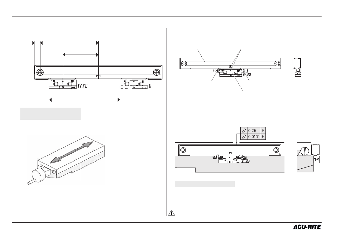
Alignment brackets (2x)
Cable assembly
Reading head assembly
Align the center marks on the reading head and scale assembly
by sliding the reading head and brackets along the scale.
F = Machine guideway
Locate the scale case so underside of end caps are flush
with the axis parting line.
Mark one end mounting hole location.
Alignment brackets must not be removed until instructed.
Page 7

SENC 150
Mounting possibilities Determining cable direction
2 Mounting information
Flush
mounting
Offset
mounting
Backup spar
mounting
Space of ≤4.5 mm (≤0.18”) use
reading head leveling screws!
Use reading head leveling set screws when surfaces are
not flush.
Detailed information about mounting possibilities on page 11
(Mounting the encoder without backup spar) and on page 14
(Mounting the encoder with backup spar).
Determine cabel exit direction before mounting the encoder.
To change the cable exit direction, remove the cover plate
and rotate it by 180°.
K1 - cable exit right side
Do not pull out the PCB!
1
K2 - cable exit left side
1
1
1
1
T-10 torx screw
Do not clamp the wires!
1
T-10 torx screw
max. 70 Ncm!
7
Page 8

3 Encoder dimensions
SENC 150
8
Page 9

SENC 150
3 Encoder dimensions
ML = Measuring length [mm]
LL = Measuring length [inch]
OT = Overtravel 1.75”
S = Beginning of measuring length
K = required mating dimensions
H1 = for ML ≥ 625 mm to ≤ 1550 mm use mid-point fastening
for ML ≥ 24” to ≤ 60” use mid-point fastening
= Direction of scanning head motion for output signals
in accordance with interface description
F = Machine guideway
9
Page 10

4 Backup spar dimensions
SENC 150
Encoder
ML (mm)
Encoder
LL (inch)L(mm)L(inch)L1(mm)L1(inch)L2(mm)L2(inch)
50 1 185.50 7.303 29.25 1.152 127 52
75 2 211.50 8.327 42.25 1.663 127 52
100 3 236.50 9.311 54.75 2.156 127 52
124 4 261.5 10.295 67.25 2.648 127 52
150 5 287.50 11.319 80.25 3.159 12 7 52
175 6 312.50 12.303 29.25 1.152 254 10 2
200 7 388.50 13.327 42.25 1.663 254 10 2
225 8 363.5 14.311 54.75 2.156 254 10 2
275 10 414.50 16.319 80.25 3.159 254 10 2
300 11 439.50 17.303 92.75 3.652 254 10 2
325 12 465.50 18.327 105.75 4.163 254 10 2
350 13 490.50 19.311 36.60 1.441 417.3 10 2
375 14 515.50 20.295 130.75 5.148 254 10 2
400 15 541.50 21.319 16.75 0.659 254 10 3
425 16 566.50 22.303 29.25 1.152 254 10 3
475 18 617.50 24.311 54.75 2.156 254 10 3
525 20 668.50 26.319 80.25 3.159 254 10 3
575 22 719.50 28.327 105.75 4.163 254 10 3
600 23 744.50 29.311 118.25 4.656 254 10 3
625 24 769.50 30.295 130.75 5.148 254 10 4
675 26 820.50 32.303 29.25 1.152 254 10 4
No.
holes B
Encoder
ML (mm)
Encoder
LL (inch)L(mm)L(inch)L1(mm)L1(inch)L2(mm)L2(inch)
725 28 871.50 34.311 54.75 2.156 254 10 4
775 30 922.50 36.319 80.25 3.159 254 10 4
875 33 998.50 39.311 118.25 4.656 254 10 4
925 35 1049.50 41.319 11.25 0.443 256.75 10.108 5
950 36 1074.50 42.303 29.25 1.152 254 10 5
1000 38 1125.50 44.311 54.75 2.156 254 10 5
1050 40 1176.50 46.319 80.25 3.159 254 10 5
110 0 42 1227.50 48.327 105,75 4.163 254 10 5
1250 48 1379.50 54.311 54.75 2.156 254 10 6
1350 52 1481.50 58.327 105.75 4.163 254 10 6
140 0 54 1531.50 60.295 130.75 5.148 254 10 6
1550 60 1684.50 66.319 80.25 3.159 254 10 7
1675 65 1811.50 71.319 143.75 5.659 254 10 7
1850 72 1989.50 78.327 105.75 4.163 254 10 8
2000 78 2141.50 84.311 54.75 2.156 254 10 9
2150 84 2293.50 90.295 130.75 5.148 254 10 9
2300 90 2446.5 96.319 80.25 3.159 254 10 10
2575 100 2700.50 106.319 80.25 3.159 254 10 11
2825 11 0 2954.50 116.319 80.25 3.159 254 10 12
3075 120 3208.50 126.319 80.25 3.159 254 10 13
H2 for ML ≥1675 mm (65”)
backup spar included
in items supplied
for ML ≤1675 mm (65”)
backup spar optional
B = Number of holes
No.
holes B
10
Page 11

SENC 150
5 Mounting the encoder without backup spar
A variety of mounting conditions can be accomodated.
The machine configuration determines the brackets required
to mount the linear encoder.
Two typical mounting conditions are shown: flush and offset.
All fasteners shown on this page are supplied with the encoder
hardware.
Flush surfaces
1
2
3
M6 x 25 mm BHCS
1 3
(1/4”-20 x 1” BHCS)
M6 flat washer
Mounting surfaces are flush within 0.25 mm (0.010”).
The reading head leveling screws are not required.
M4 x 25 mm SHCS low head
2
(8-32 x 5/8” SHCS low head)
(8-32 x 3/4” SHCS low head)
2
Offset surfaces
1
2
Space of ≤4.5 mm (≤0.18”) use
reading head leveling screws!
2
M4 hex nut
Mounting surfaces are offset.
Mounting without backup spar.
Use leveling screws in place of spacers or shims.
2
2
3
11
Page 12

5.1 Mounting the encoder via end holes
Bore hole pattern
SENC 150
Mounting
LL < 625 mm (24“):
Use end mounting holes.
12
P1
ML/2
1
ML
10
P2
1
2
P = Gauging point
M6 x 25 mm
1
(1/4”-20 x 1” BHCS)
M6 flat washer
M4 x 25 mm SHCS low head
2
(8-32 x 5/8” SHCS low head)
(8-32 x 3/4” SHCS low head)
Page 13

SENC 150
Bore hole pattern
5.2 Mounting the encoder via center support
Mounting
625 mm (24“) † LL
† 1550 mm (60”):
Use end mounting holes
with center support.
P1
ML/2
1
ML
P2
P = Gauging point
10
P3
M6 x 25 mm
1
(1/4”-20 x 1” BHCS)
M6 flat washer
M4 x 25 mm SHCS low head
2
(8-32 x 5/8” SHCS low head)
(8-32 x 3/4” SHCS low head)
1
M6 x 20 mm
3
2
3
(1/4”-20 x 3/4” BHCS)
M6 flat washer
13
Page 14

6 Mounting the encoder with backup spar
SENC 150
MountingMounting possibility
Space of ≤4.5 mm (≤0.18”) use
reading head leveling screws!
Flush or offset mounting with a backup spar.
Bracket used to reduce head to mounting surface gap.
Bore hole pattern
LL > 1550 mm (60”): A backup spar is required.
P1
3
3
3
P2
P3
6
1
1
1
2
M6 x 25 mm
1
(1/4”-20 x 1” BHCS)
M6 flat washer
M4 x 25 mm SHCS low head
2
(8-32 x 5/8” SHCS low head)
(8-32 x 3/4” SHCS low head)
M4 x 8 mm SHSS
3
P = Gauging point
14
Page 15

SENC 150
7 Mounting the reading head
Leveling screws Mounting the reading head with hex nut
M4 hex nut
M3 x 12 mm SHSS
Adjust the leveling set screws as follows:
Insert, but do not tighten 8-32 (M4) reading head screws
as shown on the right side.
Place a 0.025 mm - 0.075 mm (0.001”- 0.003”) shim between
the leveling set screws and mounting surface.
Adjust each set screw until a slight drag is felt on the shim.
Remove the shim before tighten the reading head screws.
Mounting the reading head
M4 x 25 mm SHCS low head
(8-32 x 5/8” SHCS low head)
(8-32 x 3/4” SHCS low head)
M4 x 25 mm SHCS low head
(8-32 x 5/8” SHCS low head)
(8-32 x 3/4” SHCS low head)
Do not tighten prior to adjusting leveling set screws.
Evenly tighten the 8-32 (M4) reading head mounting screws.
Removing the alignment brackets
Slide brackets away from reading head and cable.
Slide the brackets away from the reading head.
Remove the alignment brackets and save for future use.
15
Page 16

8 Checking the mounting
Connecting the encoder
Route the cables with slack loops
to allow for axis motion.
Secure excess cable by fastening
with clips or ties.
Attach the linear encoder connectors
to the readout.
Checking the electrical shielding
Connect a ground wire from the
terminal on the back of the readout to
the machine or earth ground.
Attach a ground wire from the machine
to a solid earth ground.
With the encoder attached to the ma chine and the cable connected to the
readout, check shielding by measuring
resistance between connector housing
and scale unit.
SENC 150
Desired value: 1 Ω max.
16
Page 17

SENC 150
Mechanical specifications Digital
Resolution 0.5 µm 1 µm 5 µm
Grating pitch 20 µm
Scale medium Light transmission reflective off of nickel coated glass
Accuracy (@ 20° C) / 1000 mm ± 3µm, ± 5µm
Max. traversing speed 60 m/min
Force required to move reading head <3.4 N
Operating environment
Temperature
Relative humidity
Storage environment
Temperature
Humidity
Weight w/armor
Connecting cable armored or vinyl Length = 4 m resp. 6 m from ML 1250 mm; connector: DE-9P
Max. cable length
Measuring lengths 50 mm – 3075 mm (1”–120”)
Reference pulse interval distance coded 50 mm
Voltage supply DC 5.1 V ±0.1 V / <220 mA DC 5.1 V ±0.1 V /< 180 mA
Protection EN 60529 IP 53 when mounted as per instructions
0° to 50° C
25 % to 95 % (non-condensing)
-20° to 70° C
20 % to 95 % (non-condensing)
Scale case: 180 g + 0.65 g/mm ML
Reading head: 60 g
Backup spar: 1 g/mm L
Cable: vinyl: 50 g/m
armored: 140 g/m
Connector: 55 g
≤ 9 m
9 Specifications
17
Page 18

10 Pin-outs
11 Output signals
Digital Differential
Pin 1 Pin 2 Pin 3 Pin 4 Pin 5 Pin 6 Pin 7 Pin 8 Pin 9
n/c green yellow blue red white brown pink gray
n/c channel
1
A+
5
channel
A-
channel
B+
channel
B-
ground Vcc, +5.1
±0.1 VDC
channel
R+
SENC 150
channel
R-
6
9
Outout signals
Parameter Digital
Output signals I
Incremental signals
Signal levels
Reference mark signal
Signal level
=(High level output current) = 20 mA
OH
VOH=(High level output voltage) >2.5 Vdc
IOL=(Low level output current) = -20 mA
VOL=(Low level output voltage) < 0.6 Vdc
Square-wave voltage signals. Channels A and B, in 90° quadrature relationship
TTL-level
Square-wave pulse
TTL-level
Channel A+
Channel A-
Channel B+
Channel B-
18
360°
0°
1
0
1
0
90°
1
0
1
0
Channel R+
Channel R-
1
0
1
0
1 count
(phased)
Page 19

SENC 150
19
Page 20

ID: 516291-22 D516291-02-A-01 05/2017
 Loading...