

Page 1
G2
ACU-RITE
®
MILLPWR
User’s Manual
Page 2
Controls of the MILLPWR
G2
Keys on console
Motion control keys
G2
Numerical keys
Key Function
ZERO key.
Key Function
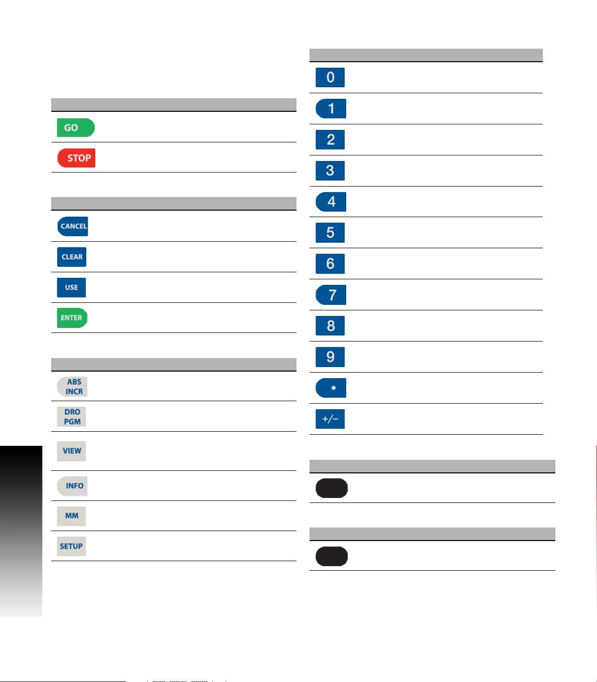
GO key (e.g. run a program).
STOP key (duel function: press once to
pause, press twice to stop a program).
Data Entry keys
Key Function
CANCEL key cancels operation, i.e. form.
Controls of the MILLPWR
Function keys
Key Function
CLEAR key clears selections, i.e. values in
a field, a program step.
USE key completes operation, i.e. data
entered in a form.
ENTER key completes selection, i.e.
values entered in a field.
ABS/INCR key toggles between Absolute
or Incremental positioning.
ONE key.
TWO key.
THREE key.
FOUR key.
FIVE key.
SIX key.
SEVEN key.
EIGHT key.
NINE key.
DECIMAL key.
DRO/PGM key toggles between the DRO
display or Program mode display.
VIEW key opens menu for setting part
graphic display parameters, i.e. type,
orientation.
INFO key opens on-screen manual.
MM key toggles between INCH or MM
mode.
SETUP key opens configuration menu.
ii
Axis Keys
Key Function
Soft Keys
Key Function
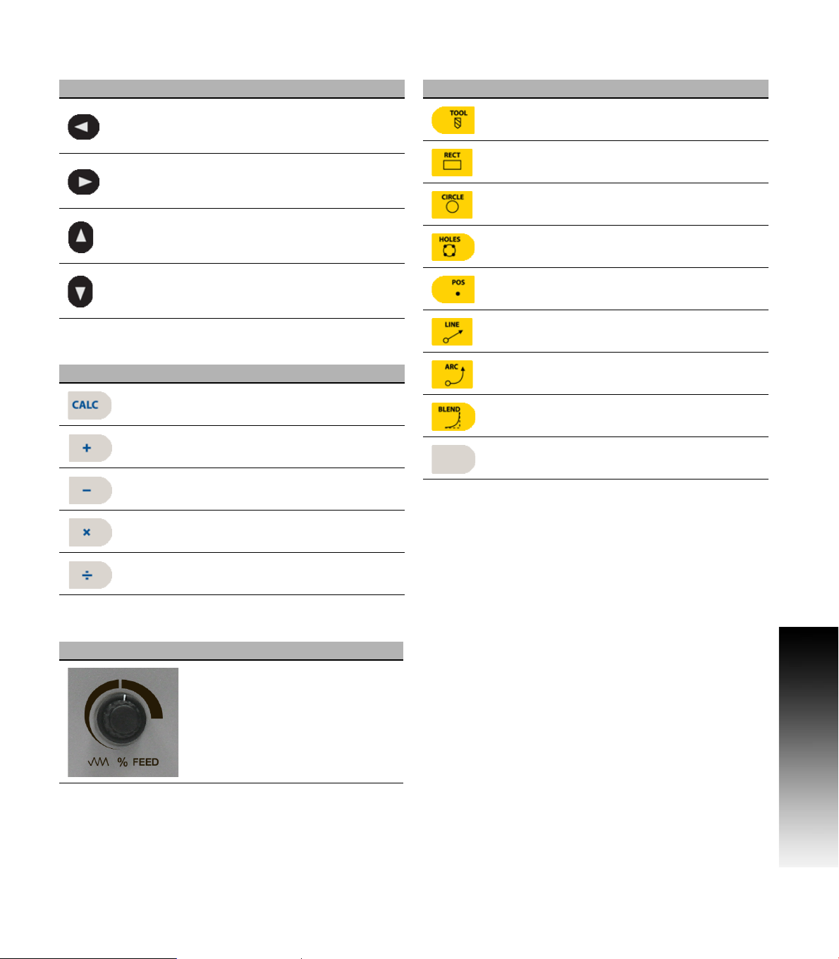
PLUS / MINUS key.
AXIS keys open the datum, or preset
form.
SOFT KEYS performs the function directly
above it.
Page 3
Move Table and Navigation keys
Key Function
LEFT ARROW key will move the table or
display cursor depending on the function
selected.
RIGHT ARROW key will move the table or
display cursor depending on the function
selected.
UP ARROW key will move the table or
display cursor depending on the function
selected.
DOWN ARROW key will move the table or
display cursor depending on the function
selected.
Calculator Function keys
Key Function
CALC key opens the calculator.
PLUS key.
MINUS key.
Milling Function keys
Key Function
TOOL key opens the SET TOOL
Dialogue.
RECT key opens the Rectangle milling
popup menu.
CIRCLE key opens the Circle milling
popup menu.
HOLES key opens the Hole pattern popup
menu.
POS key opens the POSITION / DRILL
data input dialogue.
LINE key opens the MILL LINE data
input dialogue.
ARC key opens the MILL ARC data input
dialogue.
BLEND key opens the BLEND \
CHAMFER data input dialogue.
BLANK key opens the user defined milling
function data input form.
G2
Controls of the MILLPWR
MULTIPLIER key
DIVIDE key.
Peripherals Supported:
USB memory devices; e.g. a memory stick.
Networking, USB pointing devices; e.g. a mouse, USB
keyboard.
Potentiometer for feed rate override
Feed rate override
ACU-RITE MILLPWRG2 iii
Page 4

G2
Controls of the MILLPWR
iv
Page 5

Manual Information
Message symbols
Attention!
This symbol indicates that there is one or more of the
following risks when using the described function
Danger to work piece
Danger to fixtures
Danger to tool
Danger to machine
Danger to operators
Damage!
This symbol indicates that there is risk of MILLPWRG2
damage, or electrical shock if instructions are not adhered
to.
Different from machine to machine!
This symbol indicates that instructions may apply
differently from one type of machine to another type of
machine.
Manual Information
Refer to another Manual!
This symbol indicates that information required is located
elsewhere (i.e. Machines Owner Manual).
Advice!
This symbol indicates that an Advice tip is being provided.
Important, and/or additional information about the function
described.
ACU-RITE MILLPWRG2 v
Page 6

Fonts Used in this manual
Reference to the: Console HARD KEYS.
Reference to the: Display Screen Soft Keys.
Reference to the: Display Screen DIALOGUES.
Reference to the: Display Screen FIELDS.
Changes (errors)
HEIDENHAIN CORPORATION is continuously striving to improve.
Please help HEIDENHAIN CORPORATION by sending your request to
the following e-mail address: sales@heidenhain.com
Visit www.ACU-RITE.com for latest version of this manual.
Manual Information
Model, Software and Features
This manual describes functions and features provided by
MILLPWR
Console model NC software number
ACU-RITE MILLPWRG2 Software 751005-01
The machine tool builder may not allow some of the functions
described in this manual, therefore they may not be among the
features provided by the MILLPWR
The machine tool builder representative can assist with becoming
familiar with the features of the machine.
Many machine manufacturers, as well as HEIDENHAIN Corp., offer
programming courses for the MILLPWRG2. We recommend these
courses as an effective way of improving your programming skill and
sharing information and ideas with other MILLPWRG2 users.
Intended place of operation
The MILLPWR
areas. Refer to the respective installation manual for additional
information.
G2
as of the following NC software number.
G2
on your machine tool.
G2
is intended for use primarily in industrially-zoned
vi
Page 7

New Functions of Software
751005-01-01
Zero Incremental was added to Section 2.2.
Manual Information
ACU-RITE MILLPWRG2 vii
Page 8

Changed Functions of Software
751005-01-01
Blend/Chamfer information input in Section 8.1 has been redefined.
Preset Moves information input in Section 2.2 has been redefined.
Display:Peck\Pass in Section 9.1 has a note added that the limit of
pecks or passes is 9999.
751005-01-02
The off-line software described in Section 11.1now requires the
purchase of a USB Protection Module for operation.
Custom Pocket: The tool path for custom pockets and islands,
Manual Information
described in Section 8.2, has changed to use the programmed
cutting convention.
751005-01-03
A message box warning that the table limits are not established prior
to homing was added to Section 1.1.
751005-01-04
Part Graphics: The show tool path and show step number options
were removed from the graphics view in Section 5.1.
Probing examples were added to Section 6.1.
viii
Page 9
MILLPWRG2 Access Code
Access Code
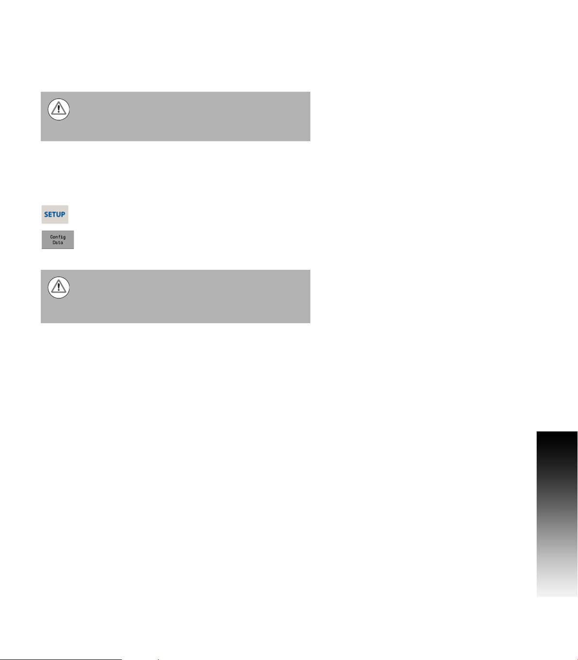
Attention!
The parameter access code is 8891
Access to Machine Parameter Operations
The access code must be entered before the installation setup
parameters can be accessed or changed.
Press the SETUP key to enter the Job Setup dialogue.
Press the Config Data soft key, and enter the access
code in the yellow message bar.
Attention!
To prevent setup parameters from being changed, remove
this page from the manual after initial system setup.
Retain this information in a safe place for future use.
Access Code
G2
MILLPWR
ACU-RITE MILLPWRG2 ix
Page 10

Access Code
G2
MILLPWR
x
Page 11

Table of Contents
Controls of the MILLPWR
Keys on console........................................................................................................ii
Motion control keys .............................................................................................ii
Data Entry keys....................................................................................................ii
Function keys.......................................................................................................ii
Numerical keys ....................................................................................................ii
Axis Keys .............................................................................................................ii
Soft Keys..............................................................................................................ii
Move Table and Navigation keys .............................................................................iii
Calculator Function keys.......................................................................................... iii
Potentiometer for feed rate override ....................................................................... iii
Milling Function keys ............................................................................................... iii
Peripherals Supported: ............................................................................................ iii
G2
Manual Information
Message symbols.....................................................................................................v
Fonts Used in this manual ..................................................................................vi
Model, Software and Features ................................................................................vi
Intended place of operation ................................................................................vi
MILLPWRG2 Access Code
Access Code............................................................................................................ix
Access to Machine Parameter Operations ..............................................................ix
1.1 MILLPWR
ACU-RITE conversational, and G-code format ......................................................... 2
Powering Up ............................................................................................................ 3
E-STOP and Shutdown ............................................................................................ 4
Find Home ............................................................................................................... 6
Disengage Z Axis feature......................................................................................... 7
Disengaging the Z axis drive:.............................................................................. 7
Re-engaging the Z axis drive............................................................................... 7
Writing Programs..................................................................................................... 8
Overview............................................................................................................. 8
G2
1.2 Operating in 2 Axes and 3 Axes Modes
Overview ................................................................................................................. 9
Program Steps in 2 Axis Mode ................................................................................ 9
Selecting 2 Axis Mode on 3 Axis Systems ............................................................ 10
ACU-RITE MILLPWRG2 xi
Page 12

1.3 Console
Operating Console ................................................................................................. 11
Rear Panel.............................................................................................................. 11
Screen Navigation.................................................................................................. 12
DRO Mode display............................................................................................ 12
PGM Mode display ........................................................................................... 12
Dialogues, and Drop Down Menus........................................................................ 13
Operator Prompts ............................................................................................. 13
Cursor ............................................................................................................... 13
General Operating Guidelines ................................................................................ 14
Operating Modes.............................................................................................. 15
Popup Menus ................................................................................................... 16
Keyboard........................................................................................................... 17
Special Characters ............................................................................................ 17
Navigational Soft keys ...................................................................................... 17
Editing Keys ...................................................................................................... 18
Calculator ............................................................................................................... 18
Numeric Keypad ............................................................................................... 18
Context Sensitive Help .......................................................................................... 19
Using Context Sensitive Help ........................................................................... 19
Console Keypad ..................................................................................................... 20
1.4 Operating Mode Screens
Display navigation .................................................................................................. 21
DRO display screen ............................................................................................... 21
Program Display Screen ........................................................................................ 22
1.5 Accessories
Electronic Edge Finder........................................................................................... 22
2.1 Conventions
Axis Conventions ................................................................................................... 24
Count Direction................................................................................................. 24
X axis ................................................................................................................ 24
Y axis ................................................................................................................ 24
Z axis................................................................................................................. 24
Cartesian Coordinates............................................................................................ 24
Polar Coordinates................................................................................................... 24
Absolute and incremental work piece positions .................................................... 25
Absolute work piece positions.......................................................................... 25
Incremental work piece positions..................................................................... 25
Setting the datum .................................................................................................. 26
Overview .......................................................................................................... 26
xii
Page 13

2.2 Manual Machine Positioning
Move Table ............................................................................................................ 27
Changing the Mode .......................................................................................... 27
Incremental Moves ........................................................................................... 27
Continuous Moves............................................................................................ 27
Adjusting the Feedrate...................................................................................... 28
Preset Moves.................................................................................................... 28
Zero Incremental............................................................................................... 28
3.1 DRO Manual Data Input
Overview ............................................................................................................... 30
DRO Screen........................................................................................................... 31
Status Bar Display.................................................................................................. 32
Move Table ............................................................................................................ 33
Milling Function ..................................................................................................... 33
Zeroing an Axis ...................................................................................................... 34
Teach Position ....................................................................................................... 34
Electronic Edge Finder........................................................................................... 35
Skewing ................................................................................................................. 36
Milling Function Keys............................................................................................. 37
DRO Operations .................................................................................................... 38
Rectangle milling............................................................................................... 38
Rectangle milling example................................................................................ 38
Circle milling...................................................................................................... 39
Circle milling example....................................................................................... 39
DRO Mill Cycles..................................................................................................... 40
3.2 Calculator
Accessing the calculator ........................................................................................ 41
Using the calculator to insert data .................................................................... 42
Trig Functions ................................................................................................... 42
4.1 Tool Table
Overview ............................................................................................................... 44
Tool Compensation Required Data ........................................................................ 44
Tool numbers / Tool names ................................................................................... 45
Locating the Tool Table.......................................................................................... 45
Tool Table .............................................................................................................. 46
Editing the tool table ......................................................................................... 46
Editing an existing tool...................................................................................... 47
Tool Table Structure .............................................................................................. 47
Tool table: Standard tool data ........................................................................... 47
ACU-RITE MILLPWRG2 xiii
Page 14

4.2 Tool Data
Tool-Length Offsets............................................................................................... 48
Teaching Tool Length Offsets in the Tool Table ............................................... 48
Diameter Offset in Tool Table................................................................................ 49
Tool Radius Offset ................................................................................................. 50
Moving without radius offset............................................................................ 50
Machining with radius offset ............................................................................ 51
Radius offset: Machining corners ..................................................................... 52
5.1 Programming Introduction
Program Display mode .......................................................................................... 54
Display area ...................................................................................................... 54
Program Function Screen ...................................................................................... 55
Folder View....................................................................................................... 55
Program Drawing View.......................................................................................... 56
Program Screen Display ........................................................................................ 57
Program Mode Soft Keys ...................................................................................... 58
Program Functions................................................................................................. 59
Program Functions soft keys ............................................................................ 59
View hard key ........................................................................................................ 62
Step Functions soft keys ....................................................................................... 63
Program Steps soft keys ....................................................................................... 64
Clear Program soft key .......................................................................................... 65
Save/Discard soft key ............................................................................................ 65
Run Options soft keys ........................................................................................... 66
Program Saving...................................................................................................... 67
Saving a Program.............................................................................................. 67
5.2 Program Mode Functions
Program Type Filter ............................................................................................... 68
USB Access ........................................................................................................... 68
5.3 Creating programs overview
New Part Program ................................................................................................. 69
xiv
Page 15

6.1 Conversational Programming
Programming Considerations ................................................................................ 72
“From” and “To” points ................................................................................... 72
Depth of Cut ..................................................................................................... 72
Pass .................................................................................................................. 72
Tool Offset........................................................................................................ 73
Datum Selection ............................................................................................... 73
Absolute vs. Incremental Dimensions .............................................................. 74
Continuous Milling ............................................................................................ 74
Fundamentals for Creating a Program ................................................................... 75
Entering milling steps ....................................................................................... 75
Adding/Inserting milling steps........................................................................... 76
Editing or Deleting a milling step ...................................................................... 76
Program Errors.................................................................................................. 77
Program Edited ................................................................................................. 77
Running a Program ................................................................................................ 78
Skewing a Part.................................................................................................. 78
Establishing a Datum ............................................................................................. 80
Overview........................................................................................................... 80
Steps to Establish the datum............................................................................ 81
X Axis Datum: ................................................................................................... 82
Y Axis Datum .................................................................................................... 82
Z Axis Datum .................................................................................................... 82
Retract Z ........................................................................................................... 83
Using an electronic edge finder ........................................................................ 83
Setting the datum on an edge .......................................................................... 84
Setting the datum at the centerline .................................................................. 85
Setting the datum at the center of a circle ....................................................... 85
Test the Datum Setting..................................................................................... 86
Testing a MILLPWR
Single Step........................................................................................................ 88
Dry Run............................................................................................................. 88
Graphics Only.................................................................................................... 88
Machining Your Part .............................................................................................. 89
Potentiometer for Feedrate Override .................................................................... 90
Manually Positioning the Quill .............................................................................. 91
G2
Program ....................................................................... 87
6.2 Folders
Folder Functions .................................................................................................... 92
Folders .............................................................................................................. 92
Creating a Folder............................................................................................... 92
Naming a new folder......................................................................................... 93
Deleting a Folder............................................................................................... 93
Saving a Program.............................................................................................. 93
Naming a Program ............................................................................................ 94
Deleting a Program ........................................................................................... 94
ACU-RITE MILLPWRG2 xv
Page 16

Loading a MILLPWRG2 (MPT) Program ............................................................ 95
Importing a DXF drawing .................................................................................. 96
G-code Programs ................................................................................................... 97
Loading a G-code Program ............................................................................... 97
Running a G-Code Program .............................................................................. 98
Starting or Stopping a G-code Program ........................................................... 98
G-code and M-Code Definitions............................................................................. 99
G-code .............................................................................................................. 99
M-Code Definition........................................................................................... 103
Additional G-code Conventions for MILLPWR
G2
............................................ 106
Backing Up a Program ......................................................................................... 107
Copy and Paste programs............................................................................... 107
Program Errors................................................................................................ 108
7.1 Demonstration Program
Overview ............................................................................................................. 110
Selecting Datum ............................................................................................. 110
Begin Programming ............................................................................................. 111
Selecting A Tool.............................................................................................. 111
Programming a line......................................................................................... 112
Programming an Arc ....................................................................................... 113
Programming the connecting Line.................................................................. 114
Programming the lower vertical Line .............................................................. 115
Programming the lower angle Line................................................................. 116
Programming the upper angle Line ................................................................ 117
Programming a Blend ..................................................................................... 118
Closing the contour......................................................................................... 119
Tool Change for the Bolt hole Pattern ............................................................ 120
Programming the Bolt circle ........................................................................... 121
Tool Change for the Rectangular Pocket ........................................................ 122
Programming the Rectangular Pocket ............................................................ 123
Testing the Program ............................................................................................ 124
Graphics only .................................................................................................. 124
Dry Run with table movement........................................................................ 124
Running the Program........................................................................................... 125
Tool Changes ....................................................................................................... 126
Clearing the Program ........................................................................................... 126
xvi
Page 17

8.1 Milling and Drilling
Overview ............................................................................................................. 128
Selecting A Tool.............................................................................................. 129
Repeatable Tool Length Offsets.......................................................................... 131
Programming a Tool........................................................................................ 131
Changing to a Tool of unknown length in DRO mode .................................... 131
Changing to a Tool of unknown length in a program ...................................... 133
Position / Drill....................................................................................................... 134
Line ...................................................................................................................... 135
Arc ....................................................................................................................... 136
Blend/Chamfer..................................................................................................... 137
Rectangular Milling Functions.............................................................................. 140
Rectangle Pocket............................................................................................ 140
Tool Path Description:..................................................................................... 141
Rectangle Frame............................................................................................. 142
Rectangle Face ............................................................................................... 144
Rectangle Slot................................................................................................. 146
Circular Milling Functions..................................................................................... 148
Circle Pocket................................................................................................... 148
Circle Frame.................................................................................................... 150
Circle Ring....................................................................................................... 152
Circle Helix...................................................................................................... 154
Hole Patterns ....................................................................................................... 155
Row of Holes .................................................................................................. 155
Hole Frame and Array ..................................................................................... 157
Bolt Circle Patterns ......................................................................................... 159
8.2 Additional Milling Functions
Step Functions soft key ....................................................................................... 160
Explode ........................................................................................................... 160
Reverse Step .................................................................................................. 161
Reverse Path................................................................................................... 161
Change Steps.................................................................................................. 162
Shift Steps ...................................................................................................... 162
Delete Steps ................................................................................................... 163
Copy/Move Steps ........................................................................................... 163
Custom Pockets .................................................................................................. 164
Custom Pocket ............................................................................................... 164
Island............................................................................................................... 165
Tool Path Description for Custom Pocket, and Islands................................... 165
Contour ........................................................................................................... 166
Repeat, Rotate, ................................................................................................... 168
Repeat............................................................................................................. 168
Rotate ............................................................................................................. 168
Mirror .............................................................................................................. 169
ACU-RITE MILLPWRG2 xvii
Page 18

Other Steps ......................................................................................................... 169
Engrave Line ................................................................................................... 170
Engrave Arc .................................................................................................... 171
Comment Step ............................................................................................... 172
Dwell............................................................................................................... 173
Reference Point .............................................................................................. 173
9.1 Setup
Overview ............................................................................................................. 176
Setup .............................................................................................................. 176
Tool Table ....................................................................................................... 176
Error Log ......................................................................................................... 176
Job Setup............................................................................................................. 177
Job Setup........................................................................................................ 177
Scale Factor .................................................................................................... 178
Feed Rate ...................................................................................................... 178
Display: Peck\Pass.......................................................................................... 178
Job Clock - Parts Counter ............................................................................... 179
Probing............................................................................................................ 179
Display Grid..................................................................................................... 180
Travel Limits ................................................................................................... 180
Tool Table ............................................................................................................ 183
Error Log .............................................................................................................. 183
Service Files.................................................................................................... 184
10.1 Updating System Software
Software Update.................................................................................................. 186
Procedure for updating the software................................................................... 186
11.1 MILLPWR Off-Line Software
Off-Line Simulator................................................................................................ 188
System Requirements ......................................................................................... 188
Installation............................................................................................................ 189
Operation ............................................................................................................. 189
On Screen Keypad ............................................................................................... 190
Keyboard Shortcuts ............................................................................................. 190
Updating .............................................................................................................. 192
xviii
Page 19

Introduction
Page 20
1.1 MILLPWR
G2
The ACU-RITE MILLPWRG2 control is a workshop-oriented contouring
control that enables you to program conventional machining
operations right at the machine in an easy-to-use conversational
programming language. It is designed for milling and drilling machine
tools, with up to 3 axes.
MILLPWR
and die makers and other machinists where manual and automated
1.1 MILLPWR
operation are both useful and needed. MILLPWR
maximize your throughput by significantly reducing set-up time, scrap,
and other non-productive operations, thereby increasing your
efficiency, productivity and profitability.
The MILLPWR
productivity. The screen layout is clearly arranged in such a way that
the functions are easy to access, fast and user friendly.
MILLPWRG2 is a closed-looped system with positioning feedback
provided by ACU-RITE precision glass scales (1µm/0.00005"
resolution). MILLPWR
unique feature that enables you to easily, quickly and accurately
re-establish work piece zero after shutting down, or power loss.
G2
was developed to satisfy the wants and needs of tool
G2
has many powerful features that will improve your
G2
G2
will enable you to
G2
also includes Position-Trac™, an advanced,
ACU-RITE conversational, and G-code format
The ACU-RITE conversational programming format is a method of
writing programs; g-code (ISO) programming can be used, and run, but
can not be edited. Preview graphics in the editor illustrate the
individual machining steps for programming the contour as well as the
corresponding tool path generated. A production drawing does not
need to be dimensioned for NC programming, the MILLPWR
programmed using the dimensions directly from the production
drawing. The programming format is the same as used in previous
MILLPWR products. Always verify old programs before machining
with MILLPWRG2.
G2
can be
2 1 Introduction
Page 21
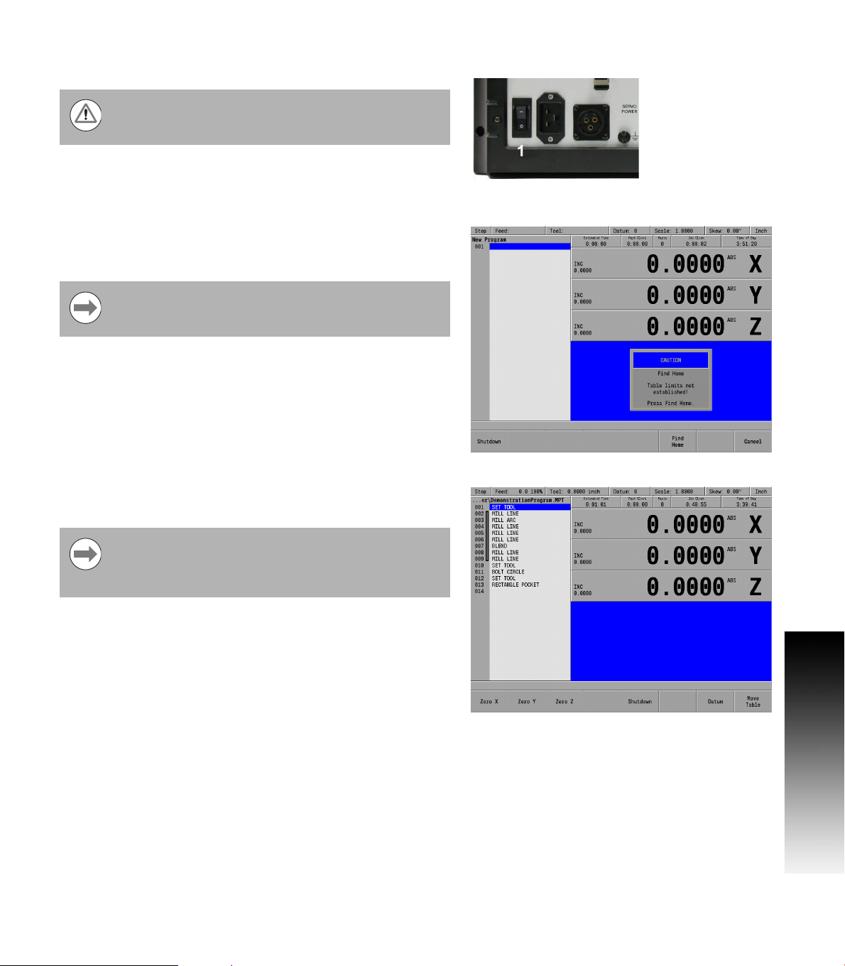
Powering Up
The MILLPWRG2 console does not disconnect the power
supply to the spindle motor. It can only be disconnected
by turning off the main power supply.
G2
Turn the power switch On [1], (to the I position) on the MILLPWR
console which is located on the back of the unit.
Follow the builder’s instructions to turn off the machine.
The start up screen with 3 soft keys will be displayed; Shut Down,
Find Home, and Cancel. After pressing either the Find Home, or
Cancel soft key, the default DRO screen will be displayed.
It is strongly recommended that the MILLPWRG2
performs the Find Home feature at start up, prior to any
other action taken.
If a program was loaded when the MILLPWR
same program will be reloaded when the unit is powered up again.
If the MILLPWRG2 did not perform the Find Home feature
at start up, press the Datum soft key from the default DRO
screen to display the Home soft key. Press the Home soft
key then the Find Home soft key will be displayed.
G2
was shut down, that
G2
1.1 MILLPWR
ACU-RITE MILLPWRG2 3
Page 22
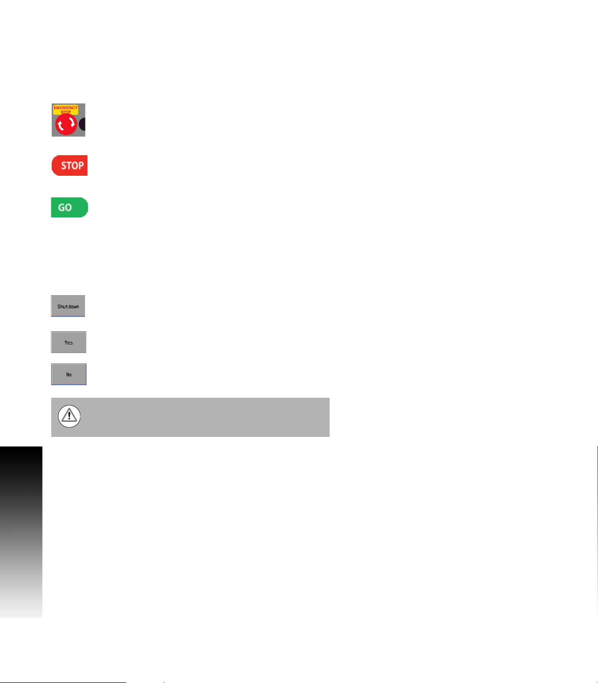
E-STOP and Shutdown
G2
The E-STOP is used for emergency program shut down by turning off
the servo motors. It does not shut down the spindle motor. The
spindle motor must always be manually stopped using the spindle
switch to stop the motor, and the cutting tool.
When the E-STOP button is pressed, the servo motors
are stopped, and the quill can be raised.
1.1 MILLPWR
When the STOP key is pressed once, the servo motors
pause, but are still active. All axes are locked, and can
not be moved.
The program can now either continue by pressing the
GO key, or stopped by pressing the STOP key a second
time.
If the STOP key is pressed a second time canceling the
program, the spindle motor must be stopped, and the
tool raised before moving any of the remaining axes.
Shutting down the MILLPWR
soft key.
Press the Shutdown soft key to shut down the
MILLPWR
DRO and PGM mode.
Confirm the shut down by pressing the Yes soft key.
G2
system is done by using the Shutdown
G2
system. This soft key is available in both
Press the No soft key to cancel and exit the shut down
procedure.
Always shutdown the MILLPWRG2 before turning power
off to the machine. Refer to the builder's instructions for
for additional information on turning power off.
4 1 Introduction
Page 23

Emergency Stop (E-STOP)
Press E-STOP to take all axes servos offline. This ends
all machine movement, and allows the quill to be
raised to move the tool out of the way.
To reset the E-STOP, turn the rotary switch clockwise in the direction
of the arrows. The switch pops outward, and is reset.
Resetting E-STOP does not reactivate the servos.
Activating/Resetting the Servos
For safety reasons, the mill powers up with the servomotors
disengaged. While the servos are disengaged the mill axes cannot
move under servo power. The axes can be manually positioned if
necessary.
Reset the servos as follows:
If a limit switch disengaged the servos, manually reposition the
machine inside its normal range of travel.
If a miscount occurs, press the Find Home soft key to reset the
servos and return all axes to their home position.
G2
1.1 MILLPWR
ACU-RITE MILLPWRG2 5
Page 24
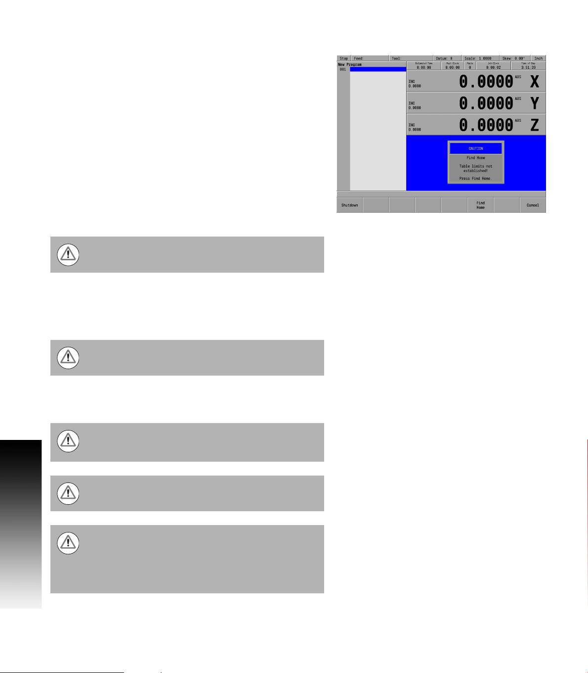
Find Home
G2
You should find home before a program is run, or immediately after
startup.
During start up, the Find Home soft key is provided on the start up
screen soft key area.
If the find home step is not performed at initial start up, it can be
initiated at any time during operation. Press the Datum soft key, then
press the Home soft key, and then press the Find Home soft key.
A 3 axes system will move the table and quill. They will
1.1 MILLPWR
automatically move a few inches along the Z, Y, and then X to find
home. If a W axis exists (i.e. coupling knee to quill) then the control
will prompt you to move the W manually to home it.
A 2 axes system will move the table. The table will automatically
move a few inches along the Y, and then X to find home. Then the
control will prompt you to move the Z quill manually to home it. If a
W axis exists (i.e. coupling knee to quill) then the control will prompt
you to move the W manually also to home it.
Before finding home with a 2 axes system, the quill must
be fully raised first.
When finding home, the MILLPWR
with ACU-RITE glass scales), the Position-Trac™ distance-encrypted
reference mark line pattern. This line pattern allows MILLPWRG2 to
accurately find home and re-establish workpiece zero from any
position.
Finding home applies to the X, Y, Z, and W axes.
Position-Trac will accurately re-establish workpiece zero after power
loss, or shut down. After home has been found, the tool’s position
(relative to the most recent datum set) will be displayed.
Not finding home before moving the table will risk
exceeding the table's travel limits, and possible damage to
the machine, and the MILLPWRG2 system.
Programs will not be allowed to run if the homing process
does not complete successfully.
The Find Home soft key is not available if there is an error,
and the front panel LED indicator is flashing.
The error must be corrected, and then cleared from the
error log. Then homing is allowed.
Refer to Chapter 9 "Error Log" on page 183 for information
on opening the error log and deleting errors.
G2
will use (on machines equipped
6 1 Introduction
Page 25
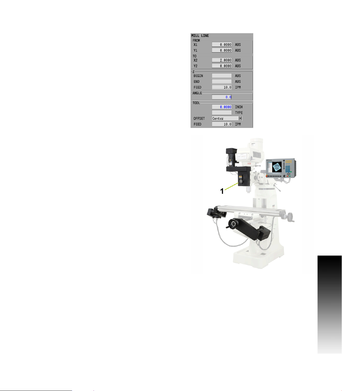
Disengage Z Axis feature
MILLPWRG2 provides the flexibility to switch between 2 axes and
3 axes operation.
Disengaging the Z axis drive:
Leave the Z BEGIN field blank when programming a step, or a one
time milling operation.
Raise the quill, then loosen the quick release knob [1] on the front of
the the Z axis drive system.
When a program step, or milling operation is then performed, the
operator is prompted to manually position the quill.
Re-engaging the Z axis drive
Raise the quill handle to seat the ball screw into the nut block (e.g.
this would be similar to hitting a dead stop).
Tighten the quick release knob [1].
G2
1.1 MILLPWR
ACU-RITE MILLPWRG2 7
Page 26
Writing Programs
G2
Overview
The MILLPWR
write a program. For operations that repeat, or complex machining it
is best to write a program. Before writing a program, determine the
work-holding device and the location of Part Zero (the point to which
all movement is referenced). Since absolute positions are defined
from Part Zero, try to select a location that directly corresponds to
dimensions provided on the part print, such as the lower left corner of
the work. Then you can develop a program. The following is a general
1.1 MILLPWR
approach to programming:
First, select the unit of measurement (Inch/MM) using the MM key.
This will place the DRO in the required unit of measure, and all
dialogues will use the selection. If the selection is changed after
data has been entered, the MILLPWR
new unit of measure.
The first step in a program selects the tool that is to be used. It’s size
can be entered in either Inch or MM regardless of the unit of
measure selected in the DRO. The Tool dialogue provides fields for
data input for the tool position. This is a tool change position, a
location away from the work area where the axes can return for safe
tool changing. TOOL POSITION will use the unit of measure that has
been selected for the DRO.
The remaining steps in the program describe the required moves,
single cycles, and Tool changes to complete the machining.
The next to the last step in the program returns the axes to the Tool
change position and ends the program.
After writing a program, verify it. Run it to troubleshoot for errors.
Verify that all programmed moves are safe, and accurate to the part
print dimensions.
Setup the work piece into the intended holding device.
First run the program in Single-Step Mode to verify that both the
program and the setting of Tool Offsets are correct. Single-Step
Mode allows you to run the program step-by-step. Make any
necessary corrections. Once verified, the program can be run in
Auto Mode.
When the finished program is ready for production, back it up on a
USB memory device.
G2
allows many features to be used without having to
G2
will convert the data to the
If there is an interruption to the power supply, the program
is not lost. The program is periodically saved. Verify that
the most recent steps (prior to the power failure) are in the
program. The fixture zero location is also remembered.
8 1 Introduction
Page 27

1.2 Operating in 2 Axes and 3 Axes Modes
Overview
The MILLPWRG2 is capable of running a 2 axes machine (manual Z) or
a 3 axes machine with the Z being switched to manual as needed. This
User's Manual covers 2 axes and 3 axes operation. This section
provides some general guidelines. In 2 axes mode, all Z moves must
be made manually.
When running a program, the system will pause and provide a prompt
whenever a Z move is required.
The incremental DRO display will show the distance to the Z axis
target position.
Press the ABS/INCR key to toggle between absolute and incremental
display modes.
In incremental mode, a bar graph is displayed below each axis
position. A small blue indicator moves toward the center of the bar
as the incremental position approaches 0. When at 0, the blue
indicator will be centered.
After moving the Z axis to the programmed position, press the GO
key to continue running the program.
Program Steps in 2 Axis Mode
When running a program step in 2 axis mode, not all information in the
program step is used. Values may be programmed for Z Pass, Z Peck,
and Tool Retract, but they will not be used when running in 2 axis
mode.
When prompted to set Z, the incremental display will show the
distance to the Z end depth.
After drilling to depth, raise the quill and press the GO key to continue
running the program.
For pocket steps, raise the quill and press GO when prompted.
If an additional pass is needed for a step, press STOP to end
the program and run the step again.
It may also be necessary to repeat a set of steps for each
pass in a program.
ACU-RITE MILLPWRG2 9
1.2 Operating in 2 Axes and 3 Axes Modes
Page 28

Selecting 2 Axis Mode on 3 Axis Systems
To run a program in 2 axis mode, disengage the quill assembly
before pressing the GO key.
A prompt will appear indicating that the quill is disengaged.
If this is intentional, press GO and the program will run in 2 axis
mode.
To program a specific step to run in 2 axis mode:
Select POSITION for the Z operation type (drill steps).
For pockets, clear the Z begin depth field.
When the step is run, the Z axis servo motor will be turned off to
allow manual movement.
Follow all manual Z motion prompts. See "Tool Table" on
page 44 for a complete description about using the Tool
Table.
1.2 Operating in 2 Axes and 3 Axes Modes
10 1 Introduction
Page 29
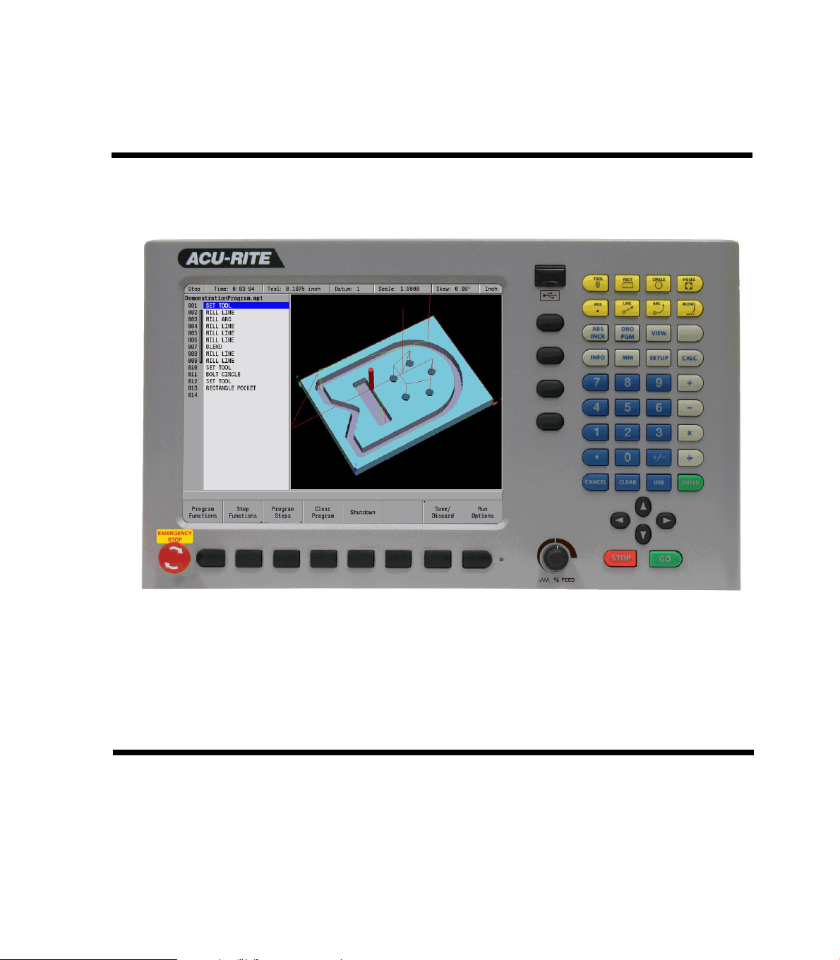
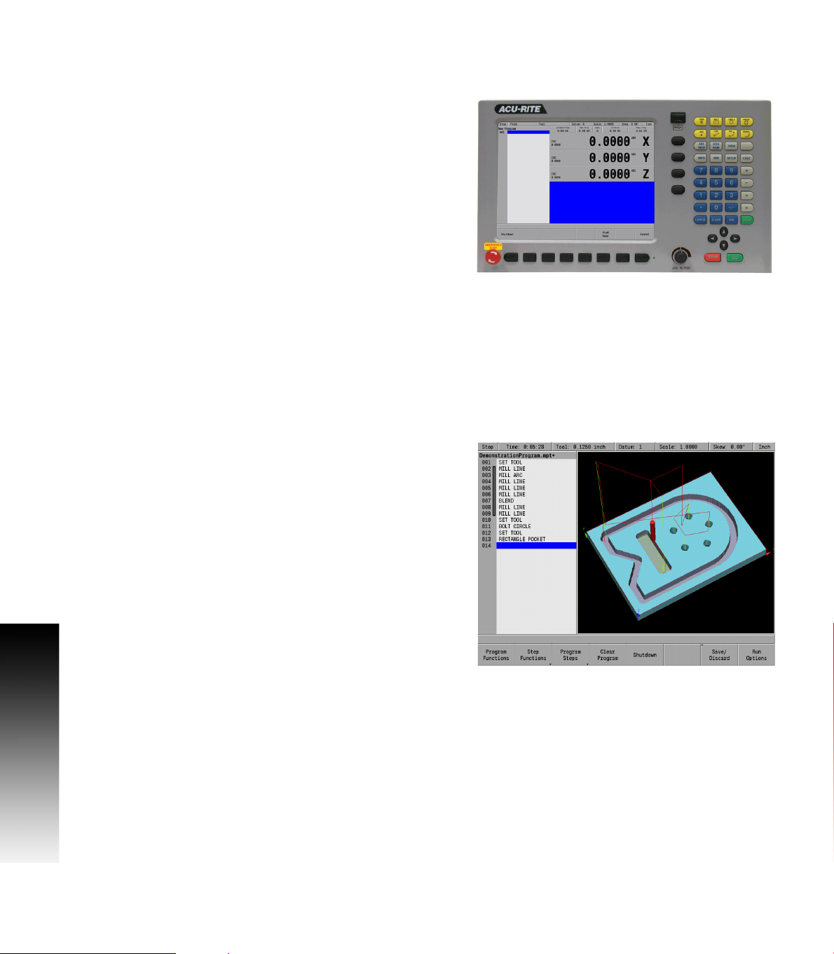
1.3 Console
Operating Console
The ACU-RITE MILLPWRG2 Console has a 12.1-inch Flat-Panel Color
Screen Display. The following list of items are located on the front
panel.
See "DRO display screen" on page 21 for mapping information of the
start up screen.
See "Console Keypad" on page 20 for a full description of the console
keypad layout. The individual keys are fully described on page ii of the
inside front cover.
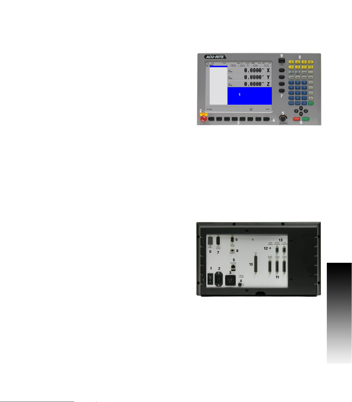
The following features are located on the front panel of the console:
1 Color flat panel screen display.
2 Emergency “E” Stop
3 Soft keys
4 Power On indicator light / Error indicator light
5 Potentiometer for feed rate override
6 Go, Pause/Stop, Navigation keys, and Move Table keys
7 Axis keys
8 Console keypad
9 USB Port
See "Calculator" on page 18 for a full description of the calculator
keypad.
1.3 Console
Rear Panel
The ACU-RITE MILLPWRG2 DRO rear panel has the following list of
items located on the panel.
1 Power switch
2 Power connector
3 Servo Power connector
4 Earth (ground) terminal
5 Ethernet port
6 USB port
7 KT 130 Edge Finder
8 Pendant (Remote switch)
9 RS-232-C connector
10 Auxiliary Machine Interface (AMI); for future expansion.
11 Servo connector (X, Y, and Z)
12 Grounding Edger Finder
13 Encoder Inputs (W and Z axis)
ACU-RITE MILLPWRG2 11
Page 30
Screen Navigation
The MILLPWRG2 display layout changes between DRO Mode and
PGM (Program) Mode by pressing the DRO/PGM key. The following
illustrates the differences between the two screen modes.
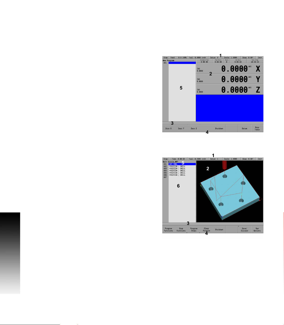
DRO Mode display
In general, the display changes as different functions are activated.
1.3 Console
Soft keys in the lower display area change per the function selected.
Soft keys perform their associated function by pressing the key
directly below it. Basic procedures and features remain the same
regardless of which mode is selected. For a complete description of
the display areas see "DRO Screen" on page 31.
1 Status Bar display for Servo Motor Status, Feed rate, Tool,
Datum, Scale, Skew, (Inch/MM), Estimated Time, Part Clock,
Parts (run), Job Clock, and Time of Day. See "Status Bar Display"
on page 32.
2 Axes Display (current position).
3 Operator Intervention Message line (OIM).
4 Soft keys display area.
5 Dialogue box display area for milling functions.
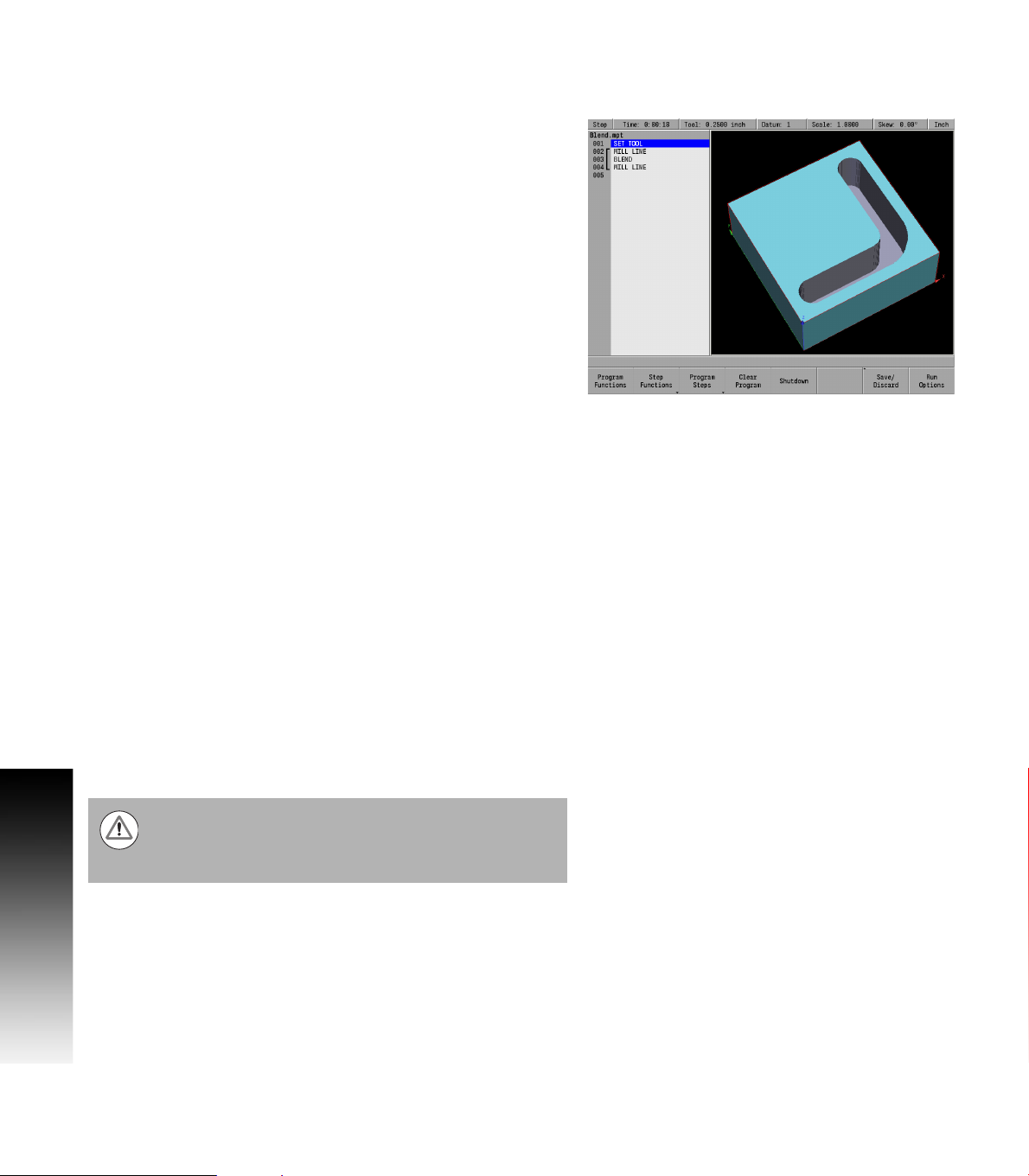
PGM Mode display
When PGM mode is selected, the display changes from DRO mode to
display program functions and graphics. Soft keys change to
programming functions. All soft keys are run by pressing the
corresponding hard key located directly below it. See "Status Bar
Display" on page 32 for complete descriptions.
1 Status Bar display for Servo Motor Status, Estimated Time, Tool,
Datum, Scale, Skew, (Inch/MM).
See "Status Bar Display" on page 32.
2 Display window of graph simulation.
3 Operator Intervention Message (OIM).
4 Soft keys display area.
5 Program name.
6 Program steps.
12 1 Introduction
Page 31

Dialogues, and Drop Down Menus
This manual provides complete information where specific examples
of actions are being explained.
As a general overview of the dialogues provided by the MILLPWR
several fields are likely to be provided for input. To navigate a dialogue,
use the ARROW keys to select the desired field. After entering the data
into a field, press either the ENTER key, or the UP or DOWN ARROW keys to
move to the next field. Exiting a field with one of these key methods
will retain the entered data in that field.
When the required data has been entered, press the USE key to accept
the data entered for use in that specific function.
Most dialogues contain Drop Down menus. Specific milling functions
may require additional information. The choices available are provided
in a drop down menu. In most cases, they are also provided as soft
keys. The choices can be selected from either location.
Operator Prompts
For actions that require immediate input to continue the operation an
operator prompt will be displayed by the MILLPWR
bar. The required data can be entered with the numerical keypad, and
in some instances using the alphanumeric on screen keyboard.
Cursor
The MILLPWRG2 uses a highlighted cursor to mark a field for selection
or editing. In some instances, the cursor will default to a field without
highlighting the field. Use the ARROWS keys to move the cursor. The UP,
and DOWN ARROWS move the cursor through the fields available. The
RIGHT ARROW will open a field that contains more choices, or subfolders
in the folder tree. The LEFT ARROW will close the menu, or subfolders.
The cursor will also change from a highlighted bar to a text cursor
when a field selected is having data entered.
G2
in the message
G2
,
1.3 Console
ACU-RITE MILLPWRG2 13
Page 32

General Operating Guidelines
General operating guidelines for the MILLPWRG2.
Additional operation soft keys are located in the soft key area along
with task selection, and dialogue. The soft keys change in relation
to the task being performed.
Selection of a particular soft key that requires additional information
1.3 Console
may open a popup menu [1].
A soft key may open a dialogue menu that requires input necessary
to continue with the operation selected.
The status bar in the top of the display is constant, and reflects only
what has been selected for the current program.
Use the Context Sensitive Help (INFO key) feature when assistance
is desired. This is an intuitive feature that aids the user by going
directly to the section in the manual in relation to the feature, or key
that has been selected to obtain assistance with.
14 1 Introduction
Page 33

Operating Modes
The MILLPWR
(Program). These are accessed from the front panel hard key. This is a
toggle key.
A USB pointing device e.g. mouse, trackball, etc. may also be used.
If a pointing device is being used, the action of clicking on a soft key
button is the same as pressing the corresponding soft key. A USB
keyboard can also be used for data entry and cursor control.
G2
has two main operating modes: DRO, and PGM
DRO mode shows the current position of each axis
relative to current datum. In DRO mode, manual
machining, and Single Cycles can be performed. Tool
selection, units, along with most setup features can
be accessed.
Program mode PGM, displays the list of program steps
and part-view graphics. New programs can be
created as well as editing existing programs.
Programs, new or existing, can be saved, deleted, or
copied using program functions.
1.3 Console
ACU-RITE MILLPWRG2 15
Page 34

Popup Menus
Within the soft keys, additional features may be available in program
mode. A soft key that has a down arrow in the lower right hand corner
indicates that additional soft keys are available for that feature.
As an example, pressing the Program Steps soft key (in PGM mode)
opens another set of soft keys available for this function. Then you will
notice an up arrow on most of the soft keys. This indicates a popup
menu will open when that key is pressed.
1.3 Console
Soft keys for PGM provide access to edit existing programs, or
create a new program. Sub menus provide dialogue for machining
operations such as milling a line, an arc, engraving, drilling and
creating pockets.
Pressing the required operation step soft key will open a popup menu
to further define the machining operation required.
A selection for a popup can occur in one of two ways:
Use the shortcut number to the left of the feature; for example,
pressing 9 on the numeric keypad will select the Circle Ring
dialogue.
Or use the Up and Down arrow keys to highlight the feature to be
used, then press ENTER.
When the type of machining operation has been selected, the
corresponding dialogue opens so that the required data can be
entered.
A dialogue in DRO mode will retain the previous data entered making it
possible to re-run the previous operation without having to re-enter all
the data.
At anytime when entering data into a dialogue the calculator can be
accessed by pressing the CALC key.
Soft keys for CALC provide access to additional math functions such
as trig functions.
When a dialogue is activated, it is not possible to change
to another dialogue. The current dialogue must be exited
by pressing USE to save the data in the dialogue or pressing
CANCEL to discard the data.
16 1 Introduction
Page 35

Keyboard
An on screen QWERTY keyboard will automatically popup when you
enter a field that requires text information input.
The keyboard becomes visible (popup) when text, and numerical
information is required for an action (e.g. saving a program, or
entering text for engraving).
Use the ARROW keys for navigation of the cursor to go to the desired
character and press ENTER to select the character.
When the information has been entered using the keyboard, press
the Save soft key. The keyboard will disappear from the screen. The
keyboard will also be removed from the screen when the CANCEL key
is pressed.
When using a USB keyboard, the on screen keyboard can be
disabled by pressing the Keyboard soft key. The on screen keyboard
will remain disabled untill it is enabled by pressing the Keyboard soft
key again. When the console goes through a power cycle, the key
board will retain its setting prior to the power cycle.
Special Characters
The keyboard also provides a “Special Characters” display which is
accessed by the “(#*\!...” key.
Arrow over to the “(#*\!...” key to highlight the key, and press the
the ENTER key.
1.3 Console
Navigational Soft keys
The following navigational soft keys are always available on the
keyboard.
The “Up Arrow” key switches the keyboard from
upper to lower case letter mode, or from lower to
upper case letter mode depending on the current
keyboard mode.
The “Abc” key switches the keyboard from the
special character key mode to the alpha numeric key
mode.
The “(#*\!...” key switches the keyboard from the
alpha numeric key mode to the special character key
mode.
ACU-RITE MILLPWRG2 17
Page 36

Editing Keys
The following keys are available for editing text on the keyboard.
The Copy key will copy the highlighted text in the text
field.
The Paste key will paste to the text field text that was
previously highlighted, and copied.
1.3 Console
The Clear key will remove all text in the text field.
The back space key will delete text in the text field one
character at a time.
Calculator
Numeric Keypad
The numeric keypad on the front of the console resembles a standard
calculator with keys for numbers 0 through 9, four math function
symbols (+, -, x, and ÷), a decimal point, and a positive/negative sign
(+/-).
The calculator is accessible from nearly any screen or
field. Press the CALC key to access the “stand-alone”
calculator. The math function soft keys are displayed
in the soft key area. Calculations can be entered
directly into a highlighted field.
Using the calculator in an entry field in a dialogue requires
the operator to press the ENTER key to run the calculation.
To move to the next field using the ENTER key requires the
operator to press ENTER a second time.
Anytime data is entered into an entry field in a dialogue
and the value is changed using the +/- key, the operator is
required to press the ENTER key to use the value change.
Moving to the next field using the ENTER key requires the
operator to press ENTER a second time.
18 1 Introduction
Page 37

Context Sensitive Help
The MILLPWRG2 uses an intuitive method to aid the user when
assistance is required. When assistance is needed with a feature, the
User Manual can be displayed directly at the point which describes the
feature.
To use this help, in this example, the console is in PGM mode, and a
Linear Engraving cycle is being programed. It is desired to see
descriptions of the cycle parameters, and the cycle itself. The
following steps describe the actions needed to take.
Using Context Sensitive Help
Press the INFO key to open the on screen User
Manual.
This will display a new window containing the section in the User
Manual, opened directly to the description of the desired feature.
This is the active window when Context Sensitive Help is activated.
To activate the Contents View on the left side of the display, press
the Contents View soft key. This allows the user to see all available
topics from the User Manual. The Forward and Back soft keys will
navigate the users previous history. The Previous Topic and
Next Topic soft keys will select the previous and next topic in the
manual contents (shown in the Contents View on the left hand side).
These soft keys allow the user to select other sections of the User
Manual while in Context Sensitive Help. Using these keys will
navigate the User Manual even if the Contents View is hidden.
The following describes the action, and use of the soft keys:
The Back soft key navigates one page back per key
press to a previous page that was viewed from the
history. History is not cleared when the Help Screen
is exited.
The Forward soft key navigates one page forward per
key press from the viewed pages in history.
The Previous Topic soft key navigates one Topic up
in the contents window per key press.
The Next Topic soft key navigates one Topic Down in
the contents window per key press.
The Contents View soft key is a toggle key to show/
hide the contents view on the left hand side of the
display.
To close, press the Exit soft key.
1.3 Console
ACU-RITE MILLPWRG2 19
Page 38

Console Keypad
The following keys are located on the console keypad. There is also a
quick reference guide located at the beginning of this manual on page
ii of the inside front cover.
1 Axis keys, use to select the required axis.
2 Numeric keys, use to enter numeric data.
1.3 Console
3 CANCEL key, use to cancel current action.
4 CLEAR key, use to clear selections such as values entered in a
field.
5 ARROW keys, use to navigate around the screen, and highlight
dialogue fields. Also used to move the table axes.
6 STOP key, use to pause, or stop a program that is running, or a
machine operation.
7 GO key, use to start, or resume a program.
8 USE key, use to complete an operation, i.e. data values entered in
a dialogue.
9 ENTER key, use to activate selections, and entries.
10 +/- key, use to toggle key for “Plus/Minus” data entry.
11 CALC key, opens the fully functional calculator.
12 Function keys, select appropriate key for quick access to the
function and data entry.
13 Milling function keys. Selection of appropriate key provides direct
access to the milling function dialogue.
20 1 Introduction
Page 39

1.4 Operating Mode Screens
Display navigation
The DRO mode is the default start up mode, and PGM mode can be
selected from the front panel key after start up. A condensed
description of these has been provided here on how to navigate, and
become familiar with the information that is being provided.
Complete descriptions, and details of these are provided later in this
manual, see "DRO Screen" on page 31.
DRO display screen
The MILLPWRG2 display screen provides the information required to
monitor the machine, it’s movement, programming, and more.
The default screen, or home screen, displays two main windows, and
soft keys in the soft key display area. When the console is first turned
on, the unit defaults to this screen. See "Screen Navigation" on page
12.
The DRO screen displays information per the current operation. DRO
mode allows the use of the milling function keys, or can be used as a
DRO in manual machining operations.
The system Shutdown soft key is located here as well as in PGM mode.
1.4 Operating Mode Screens
ACU-RITE MILLPWRG2 21
Page 40

Program Display Screen
From the DRO mode, press the DRO/PGM key, and the
display changes to program mode showing the
currently selected or loaded program.
When Programing a job, the display activates a graphic view of the
program. While the program is running, the operation that is being
performed is graphically shown as well. The VIEW key provides
features to configure the graphic area.
For more information, see "Program Function Screen" on page 55.
1.5 Accessories
1.5 Accessories
Electronic Edge Finder
The Electronic Edge Finder KT 3D enables the ability to teach
positions, find the center point of a circle, or locate datum (work piece
zero) by touching off on the part. Advantage of an electronic edge
finder is that it instantly senses when contact is made with the point
(even if the axis over traveled).
22 1 Introduction
Page 41

Machining Fundamentals
Page 42

2.1 Conventions
Axis Conventions
Count Direction
When programming a part using MILLPWR
tool movement are determined by the use of positive or negative
numbers. MILLPWR
positive and negative count directions for the X, Y and Z-axes:
2.1 Conventions
X axis
The table will move to the left and the tool will move to the right for
a positive count direction.
Y axis
The table will move toward you while the tool moves away from you
for a positive count direction.
Z axis
The quill will move up (away from the table surface) for a positive
count direction.
G2
has been factory set with the following
G2
, table movement and
Cartesian Coordinates
A cartesian coordinate is a position that can be measured from the
X- and Y-axes.
Polar Coordinates
A polar coordinate is a position that is defined by an angle and a
radius.
24 2 Machining Fundamentals
Page 43

Absolute and incremental work piece positions
Absolute work piece positions
Absolute coordinates are position coordinates that are referenced to
the datum of the coordinate system (origin). Each position on the work
piece is uniquely defined by its absolute coordinates.
Example 1: Holes dimensioned in absolute coordinates
Hole 1 Hole 2 Hole 3
X = 10 mm X = 30 mm X = 50 mm
Y = 10 mm Y = 20 mm Y = 30 mm
Incremental work piece positions
Incremental coordinates are referenced to a previous step within the
program, which serves as the relative (imaginary) datum. When you
write a part program in incremental coordinates, you thus program the
tool to move by the distance between the previous and the
subsequent nominal positions. Incremental coordinates are therefore
also referred to as chain dimensions.
Example 2: Holes dimensioned in incremental coordinates
Absolute coordinates of hole 4
X = 10 mm
Y = 10 mm
Hole 5, with respect to 4 Hole 6, with respect to 5
X = 20 mm X = 20 mm
Y = 10 mm Y = 10 mm
2.1 Conventions
ACU-RITE MILLPWRG2 25
Page 44

Setting the datum
Overview
Datum is the workpiece zero or absolute zero, and is a point of
reference that the MILLPWR
from.
A datum must be established for every job. Datum's location may be
indicated on the print; or the operator may establish a datum that
allows most of the part's dimensions be entered directly using the
least amount of calculations.
2.1 Conventions
When establishing datum, it may be easiest to locate a known point
on each axis, such as the corner of the part, or a location on a vise or
fixture.
Datum can be set at a point on the top surface, a position beneath the
surface, or at a point where there's no material present (such as in the
center of a circular part). Touching off the edge of a work piece using
a tool, or an edge finder can be used when establishing a datum. See
"Steps to Establish the datum" on page 81.
G2
bases all of the part's coordinates
26 2 Machining Fundamentals
Page 45

2.2 Manual Machine Positioning
Move Table
Non Cutting Mode
You can make or change jog moves when in DRO mode with the servos
on.
Jog Mode Description
Rapid Default rapid speed for continuous jogs. Actual
speed determined at machine setup, and can be
over ridden using the potentiometer.
Jog: 0.1 Conventional Jog increment set at 0.100”.
Jog: 0.01 Conventional Jog increment set at 0.010”.
Jog: 0.001 Conventional Jog increment set at 0.001”.
In mm units the jog increment is 20 microns, 200 microns and 2000
microns respectively.
Changing the Mode
Jog move modes are performed at the currently active feedrate. The
active Jog is selected by pressing the appropriate soft key, then
pressing the appropriate ARROW key to move the table in the direction
required. The up and down arrows move the table in the Y axis. The
left and right arrows move the table in the X axis. Use the soft keys
Move Z Up or Move Z Down to move the Z axis in the desired
direction.
Changing the Jogging Speed
The active jogging speed defaults to the max feed as determined by
the machine builder. The jogging speed may be changed by pressing
Clear. Enter the new speed in the dialogue and press ENTER. The new
value will remain active until set again or on the next power up.
2.2 Manual Machine Positioning
Incremental Moves
In DRO Mode, Press the Move Table soft key.
Then select the soft key Jog increment required. Then press the
arrow keys (for X and Y) or the soft keys for Z. One jog increment is
moved per arrow key press.
Continuous Moves
To manually position the machine using continuous movement,
press the Move Table soft key. Make sure none of the incremental
Jog keys are highlighted.
Press the appropriate ARROW key (or soft key) to move the table in the
direction required for the axis move. The table will move at the
currently active jogging speed. The table will move until the arrow
key is released.
ACU-RITE MILLPWRG2 27
Page 46

Adjusting the Feedrate
The Feedrate Override potentionmeter can be used to override the
currently active feedrate or rapid rate for machine moves. The switch
provides a range of 0% to 150%. Setting the switch to 100% will allow
the actual feedrate or rapid rate currently active to be used.
The machine builder determines the default rapid rate and
maximum feedrate at setup. If the MILLPWR
down, the configuration file reloads these default rates at
the next power up.
Preset Moves
The Preset feature allows the machine to be used manually like a
readout. The preset dialogue is used to set a target location. After
entering a target location, the INCR display will show the distance
between the current position to, and the target position.
Press the DRO/PGM key on the front panel to place the
MILLPWR
Press the ABS/INCR key on the front panel to place the
MILLPWR
2.2 Manual Machine Positioning
Enter the target coordinates for X, Y, and Z.
Press the Preset soft key to open the Preset dialogue.
Press the USE key to set the target and exit the Preset
G2
in DRO mode.
G2
to INCR.
dialogue.
Press the CANCEL key at any time to cancel and exit the
Preset dialogue.
Manually move the table and/or quill until the INCR axis positions are
zero. When the INCR positions are zero, the machine is at the target
position.
G2
is shut
Zero Incremental
The INCR display may be set to zero at the machines current location.
Press the DRO/PGM key on the front panel to place the
MILLPWR
Press the ABS/INCR key on the front panel to place the
MILLPWR
Press the X=0 soft key to zero the X axis.
Press the Y=0 soft key to zero the Y axis.
Press the Z=0 soft key to zero the Z axis.
G2
in DRO mode.
G2
to INCR.
The INCR display will show zero. As the table or quill are moved, the
INCR display will show the distance from the current position to the
zero location.
28 2 Machining Fundamentals
Page 47

DRO Mode and Calculator
Page 48

3.1 DRO Manual Data Input
Overview
The MILLPWRG2 is in either DRO mode or PGM mode. DRO mode allows
data input for short one step machining operations. Manual operation,
single step operation, and single commands can be entered. DRO mode
also allows the running of programs; See "DRO Operations" on page
38.
The following describes the concepts, and formats used with the
MILLPWR
DRO Screen
Status Bar Display
Move Table
Milling Functions
Zeroing an Axis
3.1 DRO Manual Data Input
Teach Position
Electronic Edge Finder
Skewing
Milling Function Keys
DRO Operations
DRO Mill Cycles
Calculator
G2
which are being introduced in this chapter.
30 3 DRO Mode and Calculator
Page 49

DRO Screen
The DRO screen displays information per the current operation. The
DRO mode allows the use of the milling function hard keys, or can be
used as a DRO in manual machining operations.
In addition to the information provided in Chapter 1 "DRO Mode
display" on page 12, the following table describes what is being
viewed on the display in DRO mode.
When the console is first turned on, the soft keys Shut Down, Find
Home, and Cancel are displayed.
Press the Find Home soft key.
After pressing either the Find Home, or Cancel soft key, the default
DRO screen will be displayed.
If the MILLPWRG2 did not perform the Find Home feature
at start up, press the Datum soft key from the default DRO
screen to display the Home soft key. Press the Home soft
key then the Find Home soft key will be displayed.
1 Status Bar displays the servo motor status Stop/Run/Pause,
feedrate override, current Tool (blank if none is selected), Datum,
Scale, Skew, unit of measure selected (Inch/MM), Estimated
Time, Part Clock, Parts (run), Job Clock, and Time of Day.
See "Status Bar Display" on page 32
2 Display current position of each axis, and relative to the current
datum.
3 Operator Intervention Message line (OIM) that provides prompts,
and messages to the operator.
4 Soft keys display. The soft keys change per the function that has
been selected. Each are activated by the associated hard key that
is directly below it. When a soft key appears as being pressed, it
is activated. If the key is not pressed in, it is not currently active.
Active soft key text changes to yellow text.
5 This window displays program steps if a program is loaded. If no
program is loaded, then this window is blank. When a function
has been selected (e.g. Pocket), its dialogue box is displayed in
this window.
3.1 DRO Manual Data Input
ACU-RITE MILLPWRG2 31
Page 50

Status Bar Display
Status Bar
Display
Program
State
Feed This field indicates the current feedrate of the table
Tool In DRO mode, this field indicates the current tool
Datum This field indicates the active Datum number.
Scale This field indicates the active Scale factor.
Description
This field indicates the program state: Stop when
program is not running, Run when program is
running, or Pause when program is paused for
operator.
or quill.
selection. In PGM mode, this field indicates the
programmed tool for the highlighted step.
3.1 DRO Manual Data Input
Skew This field indicates the active Skew angle.
Units This field indicates the active display units. All
Estimated
Time
dimensions are displayed in these units (inch or
mm). The current feedrate is displayed in these
units (inch or mm per minute).
This field indicates the estimated machining time for
the active program. This time assumes the program
runs at 100% of the programmed feeds. It does not
include the time necessary to perform manual
operations such as changing a tool.
Part Clock This field shows the cumulative running time of the
current program. The timer is reset when a program
is loaded.
Parts This field shows the number of times the current
program was run to create a part.
Job Clock This field shows the total elapsed time for the
current job. This timer is started and stopped by the
operator.
Time of
Day
32 3 DRO Mode and Calculator
This field shows the current time.
Page 51

Move Table
The Move Table soft key when pressed will turn on the servo motors.
Pressing it again will turn the servo motors off.
The desired feed rate can be set, or it can be left at 100% for rapid
feed rate. See "Adjusting the Feedrate" on page 28.
To move the table in increments, first select the soft key increment
wanted (e.g. 0.001, or 0.01, or 0.1).
A 3 axes system allows the Z axis to be moved by selecting the soft
keys Move Z Up, or Move Z Down.
A 2 axes system requires the Z axis to be moved manually.
A 3 axes system allows the X, Y, (and Z) axis can be moved
simultaneously by pressing the desired direction ARROW hard keys at
the same time.
A 2 axes system allows the X, and Y axis to be moved simultaneously
by pressing the desired direction ARROW hard keys at the same time.
Always fold in the table crank handles before moving the
table using the servos.
The axis move one increment per key press when using
step increment. The axis moves continuously until
released when using continuous jog.
3.1 DRO Manual Data Input
Milling Function
One Step Milling function may also be referred to as Single Cycle
milling functions. Most milling functions can be used as one time
machining operations as well as for programming. The BLEND key does
not support single operation. Each milling function will either open its
own dialogue or allow selection of choices from a soft key popup.
These milling function keys are described in more detail later in this
chapter.
ACU-RITE MILLPWRG2 33
Page 52

Zeroing an Axis
Pressing the Zero X, Zero Y, or Zero Z soft keys will zero the
incremental position for those axes.
A datum must be set to establish the point from which all absolute
dimensions are based.
3.1 DRO Manual Data Input
Teach Position
Whenever X, Y or Z coordinates are being entered, the Teach Position
soft key will appear, enabling MILLPWR
use the current coordinate(s). MILLPWR
G2
to be in teach mode and to
G2
will base each coordinate
on the current absolute position, and enter that position into the field
that is highlighted.
While programming, the MILLPWRG2 can switch between
the DRO and PGM screens without losing the program
that is either being created, or being edited.
G2
To teach the MILLPWR
a coordinate (while programming a milling
function e.g. Rectangle Pocket):
Use the arrow keys to highlight the X, Y, or Z axis fields.
Move your tool, indicator, or electronic edge finder to the position
you want to teach.
Press the Teach Position soft key to enter that location then press
the ENTER key.
The numeric keypad, and calculator functions can be used to adjust
the number.
Repeat the steps for each axis and each location that will be used to
teach the MILLPWR
Press USE to accept the dialogue or press CANCEL to cancel the
G2
.
dialogue.
34 3 DRO Mode and Calculator
Page 53

Electronic Edge Finder
A HEIDENHAIN Electronic Edge Finder enables you to teach
positions, find the center point of a circle, skew a part or locate datum
(also referred to as workpiece zero) by simply touching off on the part.
The advantage of an electronic edge finder is that it instantly senses
when you’ve made contact with the point even when you over-travel.
MILLPWR
electronic edge finder. Once this information has been entered,
MILLPWR
the electronic edge finder when performing any of the operations
mentioned above.
To teach a coordinate with the edge finder, highlight the appropriate
field then slowly move the table (1in/min) until the electronic edge
finder touches the workpiece. When the electronic edge finder
touches the part’s surface, the coordinate will appear in the field. The
electronic edge finder is active whenever an entry field is highlighted.
G2
lets you define the diameter and unit of measure for an
G2
will automatically compensate for the radius of the tip of
3.1 DRO Manual Data Input
ACU-RITE MILLPWRG2 35
Page 54

Skewing
The skew function automatically compensates for the offset angle of
the part when it is not perfectly parallel with either the X or Y axis.
Press the DRO/PGM key to place the MILLPWR
DRO mode.
Press the ABS/INCR key to place the MILLPWR
ABS mode.
Press the Datum soft key to open the SET DATUM
dialogue.
Enter the Datum Number in the DATUM NUMBER field.
Enter the Skew Angle in the SKEW ANGLE field.
Press the CANCEL key at any time to cancel and exit the
SET DATUM dialogue.
G2
G2
in
in
3.1 DRO Manual Data Input
Each datum has its own skew angle. When a new datum
is selected, that datum’s skew angle will be used.
To compensate for the skewed part, touch off on two or more points
along one axis, either X or Y. Use an electronic edge finder or a
mechanical indicator. At each point selected, press the Teach
Position soft key to enter the data.
Always choose a line that you want to make parallel with the table’s X
or Y axis, do not enter coordinates along a curve, along two different
lines or along a line that’s positioned at a true 45 degree angle.
MILLPWR
G2
will calculate the skew angle based upon a straight line
between the points you’ve entered.
If you’re working with a part that has a rough edge, it’s best to enter
multiple points along the straightest edge so that MILLPWRG2 can
more accurately calculate the skew angle.
The skew feature does not work with G-code programs.
Remove any skew angle prior to running a G-code
program.
36 3 DRO Mode and Calculator
Page 55

Milling Function Keys
The following describes in general, the milling function keys.
Most milling functions can be used as one time machining operations.
The BLEND key does not support single operation.
Hard Key Function
TOOL opens the SET TOOL dialogue where
information regarding the tool can be entered.
RECT opens the popup menu above the Rectangle
soft key. Choose the type of rectangle milling that is
to be done by selecting it from the popup menu. The
required dialogue will open for that choice.
CIRCLE opens the Circle popup menu above the
Circle soft key. Choose the type of circle milling
that is to be done by selecting it from the popup
menu. The required dialogue will open for that
choice.
HOLES opens the popup menu above the Hole
Pattern soft key. Choose the type of hole drilling
that is to be done by selecting it from the popup
menu. The dialogue where information can be
entered to drill a row, frame array, or a bolt circle
pattern will open.
POS opens the POSITION / DRILL dialogue where
information can be entered to move the table to a
position in the X & Y direction.
3.1 DRO Manual Data Input
LINE opens the MILL LINE dialogue where
information can be entered to mill a line.
ARC opens the MILL ARC dialogue where
information can be entered to mill an arc.
BLEND opens the BLEND dialogue while in PGM mode
where information can be entered to mill an arc,
blending two surfaces together. Also used for
chamfer.
ACU-RITE MILLPWRG2 37
Page 56

DRO Operations
The following explains a few of the machining operations that are
available. This example is providing an overview to the operator of the
MILLPWRG2 capabilities.
The RECT, or CIRCLE keys as an example access popup menus to
further refine the type of milling to be completed. Selecting the type
of milling operation required will open the dialogue for that type of
milling operation.
An operation is run by pressing the USE key. The CANCEL key can be
pressed at anytime to cancel an operation.
Rectangle milling
Press the RECT key on the front panel. The soft key is
displayed, and a popup menu appears on the display
listing the type of rectangles available for milling.
3.1 DRO Manual Data Input
Rectangle milling example
(e.g. pocket, frame, face, or slot)
Select Pocket from the popup menu.
The popup menu disappears, and the RETANGLE POCKET dialogue
is displayed.
Enter the data to mill the pocket.
An operation is run by pressing the GO key. While running a graphic
representation can be seen by pressing the VIEW key. The STOP key
can be pressed at anytime to pause, or stop an operation.
38 3 DRO Mode and Calculator
Page 57

Circle milling
Press the CIRCLE key on the front panel. The soft key
CIRCLE is displayed, and a popup menu appears on
the display listing the type of circles available for
milling.
Circle milling example
(e.g. pocket, frame, ring, or helix)
Select Pocket from the popup menu.
The popup menu disappears, and the CIRCLE POCKET dialogue is
displayed.
Enter the data to mill the pocket.
Press GO to run the circle pocket.
3.1 DRO Manual Data Input
ACU-RITE MILLPWRG2 39
Page 58

DRO Mill Cycles
The one step milling function are grouped in Four categories as shown
in these groups.
Drill Cycles
Position
Row of Holes
Rectangular Frame
Rectangular Array
Bolt Circle
Rectangular Pocket Cycles
Pocket
Frame
Slot
Face
Circular Pocket Cycles
3.1 DRO Manual Data Input
Pocket
Frame
Ring
Helix
Other one step milling features
Mill Line
Mill Arc
When a Milling Function key is selected for a single step operation,
either a popup menu is displayed, or the available soft keys for that
function are provided and its dialogue is opened. When a popup menu
appears, further selection is required, then the dialogue is displayed.
The DRO screen is also displayed, showing the current axes location.
The RECT, CIRCLE, and HOLES keys, when selected, display a popup
menu. These three keys provide additional selections to further
specify the type of machining required.
Press the milling function hard key that is to be performed in DRO
mode.
40 3 DRO Mode and Calculator
Page 59

3.2 Calculator
Accessing the calculator
The built in calculator can be used for simple arithmetic, or other math
functions. The calculator can be accessed at any time, during most
operations.
To access the calculator press the CALC key, and select
the calculator function to be used.
The following calculator soft keys are available:
Soft key Description
Sin
Trigonometric Sine function
Cos
Trigonometric Cosine function
Tan
Trigonometric Tangent function
Open Parenthesis (
Used as one of a pair to enclose a sum, or other
expression.
Close Parenthesis )
Used as one of a pair to enclose a sum, or other
expression.
3.2 Calculator
Square
Number multiplied by itself
Square Root
Square root of a number
More Cmds
(see next soft key display area)
ACU-RITE MILLPWRG2 41
Page 60

More Commands, second menu.
Soft key Description
ArcSin
Inverse function of Sine
ArcCos
Inverse function of Cosine
3.2 Calculator
ArcTan
Inverse function of Tangent
To exit the calculator press the CALC key a second time
or press CANCEL.
Press the CLEAR key to clear the entry field.
Using the calculator to insert data
The calculator can be used in the numeric field of dialogues.
Example, Milling a circle pocket:
The radius of a circle is required in the data input field, and the part
drawing provides a diameter dimension.
The diameter dimension can be entered into the dialogue field.
Make sure CALC has been pressed to activate the calculator.
Then press the Divide by key. The ( ÷ ) divide by
symbol will appear in the field showing the calculation
step.
Then press the 2 key. This will also appear in the field
as part of the calculation steps.
Then press the ENTER key, and the result will be
entered into the dialogue field.
Trig Functions
When calculating the Sine, Cosine, or Tangent of an angle, enter the
angle first (in decimal degrees), then press the function soft key.
42 3 DRO Mode and Calculator
Page 61

Tool Table
Page 62

4.1 Tool Table
Overview
When the MILLPWRG2 runs a program step that activates a tool, it
only activates the diameter, and length values on that row of the Tool
Table. The tool number, or tool type are not activated in dialogues that
have these fields. The tool type must be entered in the dialogue.
4.1 Tool Table
Tool Table values are automatically converted to their inch or
millimeter equivalents when the MILLPWR
typed values must match the current unit mode of the MILLPWR
Define and store up to 99 tools on the tool table. Type of data stored
on the Tool Table is information specific to each tool. Diameter, and
length offset are the only values used from the Tool Table.
The Tool Table can only be used with G-code programs.
Tool Compensation Required Data
G2
mode is changed. All
G2
.
You usually program the coordinates of path contours as they are
dimensioned on the work piece drawing. To allow the MILLPWR
calculate the tool center path, e.g. the tool compensation, you must
also enter the diameter of each tool you are using.
Tool data can be entered either directly in the part program or
separately in the Tool Table. In the Tool Table, you can also enter
additional data for the specific tool. The MILLPWRG2 will consider all
the data entered for the tool when running the part program.
G2
to
44 4 Tool Table
Page 63

Tool numbers / Tool names
Each tool is identified by a number between 0 and 99. The tool name
is its tool number.
The tool number 0 is automatically defined as the zero tool (empty
spindle) with the length L=0 and the diameter D=0.
Sign for the length difference ΔL
If the tool is longer than the T1 tool: ΔL>0(+).
If the tool is shorter than the T1 tool: ΔL<0(–).
The tool length offset can be entered as a known value, or use the
Teach soft key. The MILLPWR
automatically.
The tool length offset may be entered as a known value, or the
MILLPWRG2 may determine the offset automatically. To have the
MILLPWR
of each tool to the part’s Z0 surface, and pressing the Teach soft key.
This provides information to the MILLPWRG2 to determine the tool
length offset for each tool.
Tool Diameter “D”.
Enter the tool diameter ”D” directly.
G2
determine a tool’s length offset involves touching the tip
The Tool Table should not have any tool length for a tool
that is not repeatable.
G2
can determine the offset
4.1 Tool Table
Locating the Tool Table
The Tool Table is accessed from the DRO setup screen.
To activate the tool table, press the SETUP key.
Then press the Tool Table soft key.
ACU-RITE MILLPWRG2 45
Page 64

Tool Table
Editing the tool table
When the tool table is open, a new tool can be added, or an existing
tool can be edited by changing the existing information for that tool.
It is necessary to first select the unit of measurement
before entering values into the tool table.
4.1 Tool Table
To enter a new tool, a blank numbered row will need to be selected.
Using the ARROW keys, highlight the next available blank row number.
Highlight the Diameter field, and using the numeric keypad, enter
the tool diameter.
Press the ENTER key.
Arrow over to the next field and enter the tool Length if it is to be
used.
Press the ENTER key.
Arrow over to the Type field and press the ENTER key. The Type is
only for informational purpose.
From the drop down menu, arrow down to select the description of
the tool that is being added (e.g. flat end mill).
Press the ENTER key.
Continue to add additional tools as necessary.
When all tools have been added, press the Exit soft key, or USE key
to save changes to the tool table.
Press the Teach soft key. The MILLPWR
the tool length offset for the selected tool putting the
data to the length column.
G2
calculates
Additional data can be input such as Diameter Wear,
Length Wear and Plunge Angle. These fields are not
required to use the tool selected. See the Tool Table
Structure on the following page.
46 4 Tool Table
Page 65

Editing an existing tool
To edit an existing tool is similar to adding a new tool using the same
dialogues.
Highlight the desired field of the tool to be changed.
Type in the new value, then press the ENTER key.
When all changes have been made, press the Exit soft key, or USE
key to save changes to the tool table.
Only add the tool diameter and length if it is repeatable
each time it is selected.
When running G-code programming, the tool length for each tool in
the program is provided from the tool table. As an example, T1 M6
prompts the operator to load tool 1 into the spindle. The tool length
and diameter offset are retrieved for tool #1 in the tool table, and used
to adjust the tool path and Z axis position. This is repeated for each tool
used.
Tool Table Structure
Tool table: Standard tool data
Abbr. Inputs
Tool Number by which the tool is called in the
program (e.g. tool 2 = T2).
4.1 Tool Table
Diameter Compensation value for the tool diameter D.
Length Compensation value for tool length L.
Type Tool type: A popup menu appears where you
can select the type of tool being used.
D. Wear Tool diameter wear value.
(Only used in G code programs)
L. Wear Tool length wear value.
(Only used in G code programs)
Plunge Angle Angle of plunge cut.
(Only used in G code programs)
ACU-RITE MILLPWRG2 47
Page 66

4.2 Tool Data
Tool-Length Offsets
Tool-length offset is the distance from Z0 Machine Home to the tip of
the tool at the part Z0 (the surface of the work).
Tool-length offsets allow each tool used in the part program to be
4.2 Tool Data
referenced to the part surface. In an idle state, the MILLPWR
not have a tool-length offset active. Therefore, Tool #0 (T0) is active.
When T0 is active, all Z dimensions are in reference to the Z Home
position. When you program T1, all Z dimensions become referenced
to the surface on which the tool-length offset of Tool #1 was activated.
For machines that do not have a Z axis automatic homing feature, you
must set the Z0 position of the Z axis. Usually, it is the fully retracted
(Up) position of the quill or machine head. Tool-Length Offsets are
referenced to this position.
Because tools differ in length, Z0 axis (Part Zero) is not set the same
way as X0 or Y0. The tool-length offset is the distance from the tip of
the tool to the top of the part. Enter a length offset for each tool in the
Tool Table.
With tool-length offsets active, the Z axis position display reads 0.00
when the active tool moves to Part Zero. Tool-length offsets simplify
programming.
Teaching Tool Length Offsets in the Tool Table
The Tool Length Offset data is placed in the “Length” column in the
Tool Table.
Activate the Tool Table by pressing the SETUP key from
DRO mode.
Then press the Tool Table soft key.
G2
does
Select the tool number that is to be edited.
Use the arrow keys to highlight the “Length” column field.
With the tool in the spindle, move the tool down until it touches the
top surface of the work piece. This is referred to as “Part Zero”.
Press the Teach soft key. The MILLPWR
the tool length offset for the selected tool putting the
data in the length column.
48 4 Tool Table
G2
calculates
Page 67

Diameter Offset in Tool Table
When you activate a tool, you automatically activate the length offset
and diameter values recorded on the Tool Table (DRO mode only
activates a tool when GO is pressed). When a tool is activated, the
length offset is applied immediately to provide an accurate Z axis
position display.
The active diameter value is important when you program
compensated moves and use cycles with built-in tool compensation.
If tool diameter is correct, compensated moves and cycles are
performed accurately.
Enter tool-length offsets and tool diameter values on the numbered
lines of the Tool Table. The numbered lines on the Tool Table identify
the tool number (T-Code) that activates those values.
On machines equipped with collet-type tool holders, it is impractical to
use the Tool Table to store tool-length offsets. You can set tool-length
offset at tool change. Tool Table diameters are still required for
compensated moves and when using cycles that have built-in
compensation.
4.2 Tool Data
ACU-RITE MILLPWRG2 49
Page 68

Tool Radius Offset
Tool radius offset is available with the MILLPWRG2. The tool center
moves in the working plane along the programmed path or to the
programmed coordinates. When programming a part profile, the path
of the tool is a half of a diameter away from the depth of the cut.
Offset the tool to the right-hand or left-hand of the cutting edge.
“Right” or “Left” refers to the side of the cutting edge to which the
tool offsets. Program tool offset as Right or Left according to the
4.2 Tool Data
desired cutting edge.
Moving without radius offset
The tool center moves in the working plane along the programmed
path or to the programmed coordinates. Program tool offset as Center
when no radius offset is needed.
Applications: Drilling and boring, pre-positioning.
50 4 Tool Table
Page 69

Machining with radius offset
The tool center moves along the contour at a distance equal to the
radius. “Right” or “left” are to be understood as based on the
direction of tool movement along the work piece contour as viewed
from behind a moving tool.
4.2 Tool Data
ACU-RITE MILLPWRG2 51
Page 70

Radius offset: Machining corners
Outside corners:
A programmed path around the outside corners on a transitional arc
should have the feed rate at the outside corners reduced to relieve
machining stress. Typical for any great changes of direction.
Inside corners:
The operator must program the MILLPWR
the tool center paths at inside corners. From this point it then starts
4.2 Tool Data
the next contour element. This prevents damage to the work piece.
The permissible tool radius, therefore, is limited by the geometry of
the programmed contour.
Danger of collision!
To prevent the tool from damaging the contour, be careful
not to program the starting or end position for machining
inside corners at a corner of the contour.
G2
for the intersection of
52 4 Tool Table
Page 71

Program Overview
Page 72

5.1 Programming Introduction
Program Display mode
If the console has the Calculator active while in DRO mode, exit from
Calc by pressing the Calc key, returning the MILLPWR
Program Functions can not be accessed when the
Calculator is active in DRO mode.
From DRO mode, press the DRO/PGM key, and the
display changes to PGM mode. If a program is loaded,
it will be displayed, otherwise the display screen will
be blank.
The program display provides soft keys for program selection,
creating, editing, and running functions. The Clear Program soft key
will exit out of a current loaded program. The system Shutdown soft
key is provided on the PGM mode display the same as it is on the DRO
mode display. The Program Functions soft key provides access to
5.1 Programming Introduction
program management features.
Display area
Programming functions, graphics, and soft keys are provided in the
display area. Each soft key is activated by pressing the corresponding
hard key located directly below it.
1 Status Bar displays the servo motor status Stop/Run/Pause,
Time, loaded Tool (blank if none is selected), Datum, Scale, Skew,
and unit of measure selected (inch/mm).
2 Graphic display window of the current loaded program. If a
program is loaded, a graphical simulation is shown.
3 Operator Intervention Message (OIM) provides prompts, and
messages to the operator.
4 Soft keys display area. The soft keys change per the function that
is selected. They are activated by the associated hard key that is
directly below it. When a soft key appears as being pressed in, it
is activated and its text is yellow. When a soft key is grayed out,
it is not available for the current program function.
5 The name of the current loaded program is displayed above the
program steps display.
6 The program display window displays the program steps of the
current loaded program.
G2
to DRO mode.
54 5 Program Overview
Page 73

Program Function Screen
The Program Function screen displays several windows, and soft keys
which are defined in the contents of this chapter. The display area
window is briefly described in the following table. The Program
Functions soft key provides access to Network or USB memory
devices by pressing the Folder View soft key. The features of this soft
key are explained on the following page.
Press the Program Functions soft key to access
programs stored in the Console, on a Network, USB
memory devices, or to create a new program.
The Program Functions screen displays all programs that are stored in
a selected folder. The default storage folder for the console is v:\user\.
General Information and the programming steps of the highlighted
program are displayed in the lower left window [3], for a quick access
review. If a program has ran in its entirety (without errors), graphic
preview [2] is also displayed.
1 Available soft keys.
2 Program graphic preview.
3 Program steps preview.
4 Current folder selected.
5 Constant status bar.
6 List of all the programs stored in the current location (or folder).
Folder View
5.1 Programming Introduction
The Folder View soft key includes additional access to the user. The
Folders Tree [9]is displayed which allows the user to access different
folders, and narrow a search to selected program types.
Access to Network or USB memory devices is available in the Folders
Tree.
The Folder View soft key stays active until it is pressed again.
7 Displays the current program loaded.
8 Shows the type of programs being displayed (e.g. MILLPWR
or G-Code programs to be displayed; or DXF files.
9 The Folders Tree can be used when connected to a network, USB
memory devices, or folder management.
The MILLPWR
drive (e. g. a PC) as well as to the MILLPWR
To return to the Program Display Mode:
ACU-RITE MILLPWRG2 55
G2
can save programs to a USB device, or to network
The internal memory of the MILLPWRG2 is organized into
a folder structure. The default folder is the User folder.
Programs can be stored in the User folder. Additional
folders can be created to better organize programs.
Features in Program Functions allow for navigation of all
folders, USB memory devices and network folders.
G2
User folder.
G2
,
Page 74

From Folder View, press the Folder View soft key to
exit back to the Program Functions display.
Press the Exit soft key to exit back to Program Mode.
Program Drawing View
While a program is running (or being created), individual steps being
performed are graphically shown as they are being ran or created.
Pressing the VIEW hard key displays different soft keys for viewing
choices of the program. The VIEW key acts as a toggle switch, pressing
it again will remove the view soft keys and return to the previous
display. Pressing CANCEL or USE will also exit the view soft keys.
To activate the bottom menu soft keys for viewing
choices, press the VIEW key. The view soft keys are
explained on page 62.
Soft keys that have a small arrow in the upper left hand
5.1 Programming Introduction
corner indicates that a popup menu is available when the
key is selected for additional choices.
To return to the previous display, press the VIEW key
again, or the USE key.
If the CANCEL key is pressed, it will exit out of the view
mode, and return to the previous display, but will not
cancel out any view changes made.
56 5 Program Overview
Page 75

Program Screen Display
When programming a machining step, the display changes according
to the machining step selected. Once a machining step has been
selected using the Program Steps soft key, the display will appear as
shown here. The program steps display windows are described in the
following table.
1 Current program steps.
2 Dialogue for a new milling step (e.g. CIRCLE POCKET)
3 Dialogue field graphic assistant. Graphic changes per input field
illustrating information required.
4 Soft keys.
5 Program name. If an asterisk appears at the end of the name, it is
indicating that the program has not been saved since its last edit.
Soft keys that have a small arrow in the lower right hand
corner indicates that additional soft keys are available
when the key is selected. Soft keys that have up arrow in
the top left hand corner indicates that a popup menu is
available when selected.
5.1 Programming Introduction
ACU-RITE MILLPWRG2 57
Page 76

Program Mode Soft Keys
When the DRO/PGM key is selected from DRO mode, the MILLPWRG2
screen changes to PGM mode, and the program default screen is
displayed.
Keys Function
5.1 Programming Introduction
When the MILLPWR
milling functions specific to the hard key selected become
available as soft keys.
Program Functions opens additional soft keys to
Load, Save, Clear, or Copy a program along with
several other functions listed on the following page.
Step Functions opens additional soft keys for
modifying the program steps (e.g. reverse path,
delete steps, ect.).
Program Steps opens additional soft keys for
programming, or modifying an existing program by
adding addition milling functions (e.g. add a pocket,
mill a circle, etc.).
Clear Program will unload the current program when
the Yes soft key is selected. The program is not
saved. If any changes were made, they are lost.
Shutdown will shut down the MILLPWR
Only then can power be turned off.
Save/Discard opens a popup menu which provides
the choice to either save the changes made to the
program, or discard the changes by returning the
program to its original state.
G2
is set to program mode, types of
G2
system.
Run Options opens additional soft keys for running a
program (e.g. dry run, graphics only, etc.).
Once Clear Program is used the program cannot be
recovered.
58 5 Program Overview
Page 77

Program Functions
Program Functions soft keys
The Program Functions soft key provides access to the following soft
keys for saving, clearing, or loading an existing program to either edit
or run.
Soft key Function
The Load soft key will load the selected program. If
a program is currently loaded, a prompt will be
displayed asking for confirmation to clear the loaded
program. If a program is currently loaded, it must be
saved prior to pressing this key.
The Save soft key will save the currently loaded
program, or the program can be saved under a new
program name.
The Program Type soft key opens a popup Menu
providing the choices which type of programs to
display in the folder listing; MILLPWR
G-code programs, DXF drawings, All programs or All
files.
The Function soft key opens a popup Menu
providing the choices to Cut, Copy, Paste, Merge,
Rename, or Delete any program that is listed in the
folder. It does not need to be the currently loaded
program.
G2
programs,
5.1 Programming Introduction
The Select soft key allows the operator to select
one or more programs from the current folder, or
select all the programs. Select the Clear option to
un-select the current selected program(s). This
allows features within the Function soft key to be
done on the selected group of programs.
The Change Window soft key toggles the cursor
between the folder list, folder tree (if displayed) and
program list.
The Folder View soft key opens the folder tree to
access all folders, and sub folders. Use the Change
Window soft key to navigate to the available
windows.
Press the Exit soft key to return to the Program
Function screen.
ACU-RITE MILLPWRG2 59
Page 78

Pressing the Select soft key feature opens a popup
menu that provides these three choices:
The Select feature will select one or more programs. Highlight each
program to be selected, and choose Select for each program
highlighted.
The Select All feature will select all programs in the folder.
The Clear feature will un-select one or more programs that have
been highlighted. Clear does not delete a program, it will only
un-select it.
Having a program, or programs selected, use the Function soft key to
continue on taking the appropriate action required.
The Function soft key provides several choices that
5.1 Programming Introduction
The selected program(s) can be Cut from the current folder, then
moved to another folder using the Paste feature.
In the same fashion, using the Copy feature, the selected
program(s) can be copied to the same folder, or to a different folder
using the Paste feature.
Use the Merge feature to paste the contents from the selected
program to the currently loaded program at the current cursor
location. This feature is only available for MILLPWR
programs. Once this function is executed, it will exit the program
functions, and return to program view.
Use the Rename feature to rename the selected program. Only one
program at a time can be selected to use this feature.
can be executed for the action taken after using the
Select soft key feature:
G2
(.MPT)
60 5 Program Overview
Page 79

Choosing the Delete feature will delete one or more programs
selected. The message bar will be displayed showing the first
selected program asking for confirmation to delete it. Four soft keys
are displayed for deleting options.
Yes will delete the current program displayed in the message bar.
Cancel will cancel out of the current operation. Cancel will not
restore any prior deletions that had been made.
All will delete all the selected programs by automatically
answering yes to confirm deletion of each program.
No will cancel the deletion of the current program in the message
bar.
Any program that is deleted can not be recovered.
Located in the upper right folder display area are two soft keys
Forward (+), Backward (-). These keys can be accessed directly
when using a mouse. Direct console access is accomplished by
using the Plus, and Minus keys on the console keypad. The keys are
used to facilitate navigation among folders in the console, network
and USB memory devices.
Pressing the Minus key always takes you back to the previous folder
location. Pressing the Plus key takes you to the next folder in the
history. Plus is only available if Minus has been used.
5.1 Programming Introduction
The MILLPWR
history step will replace the 1st history step.
Edits to a program that have not been saved are lost.
G2
will save 20 history steps. The 21st
ACU-RITE MILLPWRG2 61
Page 80

View hard key
Once a program is opened, the first step is to select how the part
should be displayed in the graphics window. Pressing the VIEW key
displays different soft keys for graphic viewing options of the program.
Pressing the View key again, or pressing the CANCEL key will turn the
view key display off. See "Program Drawing View" on page 56.
The VIEW key provides access to the following soft keys for selecting
how the part should be viewed.
Keys Function
The Block Form (3D solid) opens a dialogue so that
the operator can specify the block size shown in the
graphic display area. MILLPWRG2 normally
calculates this but the user can adjust the values if
necessary.
The arrow keys are used to adjust the view. The
Adjust View opens a popup menu to select either
Zoom, Pan, or Rotate to have adjusted with the
5.1 Programming Introduction
arrow keys.
Change View opens a popup menu where either 2D
Line, 3D Line, or 3D solid view of the graphic display
can be selected. The default is 2D line view.
Show Grid toggles on, or off the grid display. This is
only active in 2D Line view. The grid size can be
adjusted in Job Setup; see page 177.
Show Contour is available with 2D Line and shows
the program geometry with a white line. When the
Show Step Numbers is also selected, labels are added
to the path showing which step was used to create
that portion of the path.
Reset Graphics restores the default zoom, pan, and
rotate settings.
62 5 Program Overview
Page 81

Step Functions soft keys
The Step Functions soft key provides access to the following soft
keys for assistance with programing steps, and modifying or arranging
the programs steps.
Soft key Function
The Explode soft key will explode a program step
e.g. such as a bolt circle converting it from a radius
and number of holes equally spaced to individual
coordinates for each hole. See "Explode" on page
160 for additional information.
The Reverse Step soft key will reverse the tool path
of the selected step so that it will be followed in the
reverse order.
The Reverse Path soft key will reverse the tool path
selected of all the steps so that it will be followed in
the reverse order.
The purpose of the Shift Steps feature is to
transpose a range of steps from one location to
another on the actual work piece within a program.
The Change Steps soft key opens a dialogue that will
allow the operator to select a range of steps that can
be modified for the Z axis, Offset, and Feed Rate.
The Delete Steps soft key opens a dialogue that will
allow the operator to select a range of steps, or a
step to be deleted.
The Copy / Move Steps soft key opens a dialogue
that will allow the operator to select a range of steps
to either be copied, or moved else where in the
program.
5.1 Programming Introduction
ACU-RITE MILLPWRG2 63
Page 82

Program Steps soft keys
The Program Steps soft key accesses the soft keys listed in the table
below. Each soft key (except for the Tool key) provides additional
selections on a popup menu. This allows to further define the milling
action to be programmed.
Soft key Function
The Tool soft key opens a tool dialogue to enter the
size and type of tool to be used for the following
step(s).
The Position/Milling soft key opens a popup menu
to further define the milling operation e.g. Position/
Drill, Line, Arc, Blend (Round), and Blend (Chamfer).
The Custom Pocket soft key opens a popup menu to
further define the milling operation e.g. Custom
Pocket, Island, and Contour.
The Hole Pattern soft key opens a popup menu to
5.1 Programming Introduction
further define the milling operation e.g. Row of
Holes, Rectangle Frame, Rectangle Array, and Bolt
Circle.
The Rectangle soft key opens a popup menu to
further define the type of milling operation e.g.
Pocket, Frame, Face, and Slot.
The Circle soft key opens a popup menu to further
define a milling operation e.g. Pocket, Frame, Ring,
and Helix.
The Repeat, Rotate ... soft key opens a popup
menu to further define a milling operation e.g.
Repeat, Rotate, or Mirror
The Other Steps soft key opens a popup menu to
further define the type of milling operation
e.g. Engrave Line, Engrave Arc, Comment, Auxiliary
Function, Dwell, or Reference Point.
64 5 Program Overview
Page 83

Clear Program soft key
This soft key provides a quick method to clear the current loaded
program. It does not provide an option to save before exiting. Its
function is meant to quickly clear a program (e.g. once it has been run
and is no longer needed), so that a new program can be loaded, or a
blank program is available, or return to DRO mode without having a
program loaded. If the program has been edited the operator is asked
to confirm the Clear operation. Save program changes before using
Clear. All changes are lost and cannot be recovered.
Press the Clear Program soft key to close the
program.
Save/Discard soft key
Save/Discard soft key opens a popup menu which provides the choice
to either save the changes made to a program, or discard the changes
by returning the program to its original state.
Press the Save/Discard soft key and select from the
popup menu to either save the program, or discard
the changes made to the program.
5.1 Programming Introduction
ACU-RITE MILLPWRG2 65
Page 84

Run Options soft keys
The Run Options soft key allows the program to be run and tested with
various options for a program. These options allow the operator to test
a program without actually cutting material. The Run Options must be
set before you start to run the program.
Soft key Function
The Single Step soft key will move the machine one
step at a time.
The Dry Run soft key will run the program’s tool path
at the speed defined in Job Setup. No material
should be placed within the tool path for this
function. Dry Run is intended to provide a quick
verification of the machine movements in the
program.
The Graphics Only soft key will run through the
program drawing the tool movement on the display
only. Graphics Only is intended to provide a quick
5.1 Programming Introduction
verification of the tool path in the display; no
machine movement will occur.
The Optional Stop soft key will allow the program
to be stopped at different locations to allow for
verification of particular program steps selected has
the operator. If a program has an optional stop (i.e.:
M01 in a G-code program), the system will only stop
at this block when Optional Stop is enabled. If it is
disabled, it will be skipped. The Optional Stop is an
M01 in a G-code program.
The Exit soft key will exit the Run Options function
and return to the previous display.
66 5 Program Overview
Page 85

Program Saving
When you create programs with the MILLPWRG2, they can be saved
within MILLPWR
G2
's User folder, on a USB device, or a network
location.
G2
MILLPWR
will retain a program in memory so it is not lost in the
case of a power failure.
Programs can be organized in MILLPWR
G2
, on a USB device, or a
network location; or in personalized folders that the operator can
create.
Saving a Program
A new blank program can be saved prior to having any program
steps added, a newly created set of program steps can be saved as
a new program, or an existing program can either be saved as a new
program by replacing the current name, or save the existing
program.
To save the current active program, select the Save
soft key. The keyboard will popup with the Save key
highlighted. Press the ENTER key. A prompt will ask to
overwrite the existing program. Press the Yes
softkey.
The keyboard will automatically be displayed with the current program
name highlighted in the keyboard display window (see "Keyboard" on
page 17).
The Save/Discard key is also available to quickly save a program, or
discard any changes made since the last time it was saved.
Press the Save/Create soft key to save the program
with its current name, or enter a new name for the
current program to create a new program.
5.1 Programming Introduction
A name can not be longer than 60 alphanumeric
characters. The MILLPWR
G2
displays program names as
they were entered. No two programs can have the same
name.
The program’s graphic preview is updated whenever the
program is saved. In order for the new graphic preview to
be created correctly, the program must not have any
errors. The operator must allow the program graphics to
finish drawing the program before pressing any keys.
ACU-RITE MILLPWRG2 67
Page 86

5.2 Program Mode Functions
Program Type Filter
In PGM mode, press the Program Functions soft key to display the
Folder View, and Program Type soft keys. Program type aids with
locating programs by type, and reduces the number of programs that
are displayed.
To select what type of programs to show, press the Program Type
soft key, and select which program type(s) to display using the ARROW
keys.
5.2 Program Mode Functions
USB Access
As soon as the USB memory device is inserted, its contents will be
displayed in the Folder Contents window. From here the operator
can modify, copy, delete, etc. any of the programs, or folders on the
USB device.
In PGM mode, the operator can access a USB memory device by
inserting the USB device into a USB port of the MILLPWR
From DRO mode, press the DRO/PGM to enter PGM mode.
Press the Program Functions soft key.
G2
.
Press the Folder View soft key.
The display will now show the USB device in the Folder Contents
window, and when selected, will show its content in the upper right
window.
It is recommended to copy programs from the USB
device to the user folder and use the program from the
MILLPWRG2.
Prior to removing the USB memory device, check that the
activity indicator light on the USB drive is not active or
blinking. This will ensure that all commanded disk
operations have completed, and that it is now safe to
remove the drive.
68 5 Program Overview
Page 87

5.3 Creating programs overview
New Part Program
The following briefly describes how a new program is created. See
"Fundamentals for Creating a Program" on page 75 for more complete
information.
Press the DRO/PGM key from DRO mode to enter PGM
mode.
A new program can be created from an existing program, or create
a completely new program.
To create a new program from an existing program:
Press the Program Functions soft key.
Select an existing program that will be used to create
the new program, and press the Load soft key.
Press the Program Functions soft key.
Press the Save soft key. Press the Keyboard soft key
to display the keyboard if the keyboard is not
automatically displayed. Type in the name of the new
program and select Save.
The new program is now loaded, and can be modified as required.
To create a new (blank) program:
When a program is currently loaded, press the Clear
Program soft key in the PGM mode display to clear the
loaded program from memory, and to create a new
program.
Press the Save soft key. Press the Keyboard soft key
to display the keyboard if the keyboard is not
automatically displayed. Type in the name of the new
program and select Save.
5.3 Creating programs overview
ACU-RITE MILLPWRG2 69
Page 88

5.3 Creating programs overview
70 5 Program Overview
Page 89

Programming
Page 90

6.1 Conversational Programming
Programming Considerations
“From” and “To” points
Lines and arcs are defined by their FROM point (the point where
they begin) and TO point (the point where they end).
Depth of Cut
When programming the depth of cut, MILLPWR
BEGIN and END locations for the Z axis.
The location that is entered into the Z BEGIN field tells MILLPWR
6.1 Conversational Programming
where the quill is to begin cutting at the programmed feed rate. The
END location defines the depth of the cut.
Always be sure that the BEGIN location is above the
surface of the workpiece.
Pass
PASS refers to the number of cuts or the distance (depth) of each cut
that are used to machine an area to its END depth. The operator
selects which is to be required in this field from Job Setup. In the JOB
SETUP dialogue, DISTANCE or NUMBER of CYCLES must be
selected. Which selection is chosen will appear on all dialogues where
it is required. The number of passes can be controlled by entering a
value in the PASS field (where ever it is available).
PASS is ignored on 2 axes systems. The operator must set
the depth of cut for each pass, and repeat the operation
until the full depth has been reached (see "Machining Your
Part" on page 89).
Leaving the field blank programs the MILLPWRG2 to make
the cut in the number of passes it decides is necessary.
No pass will exceed the diameter of the active tool
G2
will prompt for the
G2
72 6 Programming
Page 91

Tool Offset
MILLPWR
right offsets. Program the dimensions of the part as identified by the
part drawing.
Program a line, arc, frame, etc. using the “Tool Offset” field to tell
MILLPWR
Radius Offset" on page 50.
To determine which offset to use: If the tool needs to be on the left
side of the line, use a LEFT offset. If the tool needs to be on the right
side of the line, use a RIGHT offset.
When using a CENTER offset, the programmed dimensions are for the
center of the tool. For some milling functions, like frame and arc,
INSIDE and OUTSIDE offsets are available to make it easier to define
the tool offset.
Datum Selection
The datum is where workpiece (absolute) zero is located. See "Steps
to Establish the datum" on page 81.
If the datum isn't defined on your print, then determine the datum
based upon where most of the dimensions originate.
Pick a point which will let you enter most of the dimensions directly,
with fewest calculations.
Establishing a datum requires that the Z retract position be provided
(the position the quill returns to between program steps).
By setting a retract position, you can ensure that the tool you are
using does not make contact with your workpiece when the quill
moves from one position to the next.
Establish a retract position for the Z axis each time the console is
powered, otherwise the MILLPWR
retract position.
G2
will calculate the actual tool path when using left and
G2
which side of the line the tool is to be on. See "Tool
G2
will use the quill’s previous
6.1 Conversational Programming
A two axes system also requires the Z depth, and Z retract
position. The operator will be prompted to manually move
to a depth, or retract position.
ACU-RITE MILLPWRG2 73
Page 92
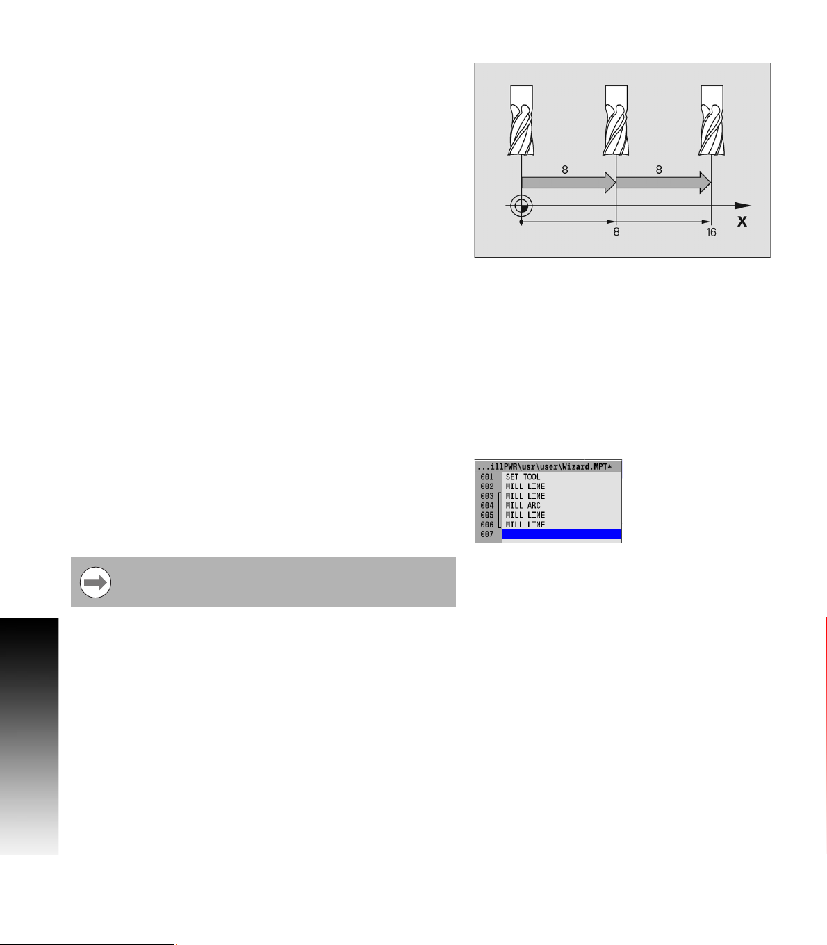
Absolute vs. Incremental Dimensions
MILLPWR
entered. A dimension measured from the point you defined as datum
is an absolute dimension. A dimension measured from any other point
is an incremental dimension. See "Absolute and incremental work
piece positions" on page 25.
The dimension moves of 8, then 8 again are incremental moves.
The dimension moves of 8, then 16 are absolute moves.
Continuous Milling
When you program a continuous contour of lines and/or arcs the
contour will cut without stopping if there is no programmed stop.
MILLPWRG2 will automatically recognize continuous contours as
you're programming. There are no special key presses or other
functions to learn.
For lines and arcs to be continuous, they must:
Be consecutive steps in a program.
Have the same depth.
6.1 Conversational Programming
Be cut with the same tool.
Be cut using the same tool offset.
Share a common “From” or “To” point (one step must end at the
point where the next one begins).
If one step follows another, then MILLPWRG2 assumes that they are
to be connected (see steps 003 through 006). The single line bracket
indicates the steps that will be machined with continuous milling.
MILLPWR
OFFSET from the previous step. The TO point must be filled in, and
then press the USE key.
G2
allows both absolute and incremental dimensions to be
G2
automatically fills in the FROM point, DEPTH, and TOOL
Different feed rates within each step of a continuous
contour are allowed, and can be used.
74 6 Programming
Page 93

Fundamentals for Creating a Program
In DRO mode press the DRO/PGM key to enter program mode.
Programs are created by developing a list of milling steps to be
performed. As steps are added to the list, each will immediately be
drawn on the screen so that it can be displayed graphically, showing
the part machining in progress.
MillPwr G2 allows a maximum of 9999 program steps.
Entering milling steps
Before any programming steps are entered, a tool must first be
selected and entered. See "Editing the tool table" on page 46.
The milling function keys are among the eight yellow keys located in
the upper right corner of the console. The function you select will
appear in the program listing and will enable you to enter the data and
add the step into the program.
Additional milling functions are available in PGM mode, and are
accessed by pressing the Program Steps soft key. Program Steps soft
keys are also displayed when RECT, CIRCLE, or the HOLES keys are
pressed in PGM mode.
To enter a milling step, press the appropriate milling function (e.g.
LINE). Some keys will open a popup menu with the soft key to
further define the type of milling step that is to be performed.
After entering the data for the program step, press the
USE key to add the step to the program.
Press the CANCEL key at anytime to exit the milling step dialogue and
not add it to the program.
6.1 Conversational Programming
ACU-RITE MILLPWRG2 75
Page 94

Adding/Inserting milling steps
A new program step number automatically appears following the
last step entered, and the new step is highlighted.
If the cursor was moved for any reason, use the arrow keys to
highlight the new step, then select the milling function to be added.
To insert a step between two existing steps, position the cursor to
the step below where the new step is to be placed.
Press the desired milling function key, and it will be inserted above
the highlighted program step.
Additional milling functions are available by pressing the Program
Steps soft key. The soft keys change, displaying several Milling
function soft keys. Each soft key when selected will have a popup
menu for further selection to refine the type of milling operation to be
entered. For example, the Circle soft key will display choices for the
type of circle to be milled; a Pocket, Frame, Ring, or a Helix.
Editing or Deleting a milling step
To edit a program step, use the arrow keys to highlight the step to be
changed and press the USE or ENTER key, or just enter a step number
using the numeric keypad.
A Goto program line number popup dialogue is immediately
displayed. The total number of lines in the program are shown in the
6.1 Conversational Programming
Line Count: field.
Enter the desired line number and press ENTER.
Press ENTER or USE again to to edit the program step.
After making the appropriate changes, press the USE key to accept
the changes and place the step back into the program. Or press
CANCEL to discard any changes to the step.
To delete a step, highlight the step to be deleted, then press the
CLEAR key.
VIEW key
If you need to see the machined part in more or less
graphic detail, press the VIEW key. This enables you to
access the viewing soft keys that are available. See
"View hard key" on page 62 for a complete description
of these soft keys.
76 6 Programming
Page 95

Program Errors
When an error is detected in a program, the step with the error is
highlighted in the program listing with a red "x" symbol. Edit the
program step to correct the error.
Additional information about the error is added to the error log. See
"Error Log" on page 183.
After correcting the errors, remember to delete them
from the error log. A quick method for deleting all errors
in the log is to press the “0” on the numeric keypad.
If there is more than one error in the program, only the
first step with an error will be highlighted. After correcting
the first error, the next error will be highlighted.
Program Edited
When a saved program is loaded, only the name and extention is
displayed.
If the saved program is then edited, the program name will show an
asterisk at the end of the name.
This tells the operator that the program has changed, but has not
been saved.
Saving the program will remove the asterisk, or exit the program
without saving the changes.
When a program that has been edited, but not saved, then it will
revert back to the last saved version when closed. The program will
not display an asterisk the next time it is loaded.
6.1 Conversational Programming
ACU-RITE MILLPWRG2 77
Page 96

Running a Program
Skewing a Part
For some machining operations it is more convenient to
use the Skew feature rather than indicating in the work
piece.
With MILLPWR
part. The Skew feature automatically compensates for the offset angle
of the part by touching off one straight edge with an electronic edge
finder or a mechanical indicator.
To skew a part touch off on two or more points along one axis, either
X or Y. Touch off and use the teach position feature.
A work piece that has a rough edge should have multiple points
entered along the straightest edge to more accurately calculate the
6.1 Conversational Programming
skew angle.
G2
, it may save time setting up a job by skewing the
Do not enter coordinates along a curve, two different lines,
or along a line that’s positioned at a 45 degree angle.
MILLPWR
straight line between the points that have been entered.
G2
will calculate the skew angle based upon a
78 6 Programming
Page 97

Setting the skew angle with an electronic edge finder:
Press the Datum softkey to open the DATUM dialogue. Highlight the
Angle field.
Press the Probe soft key.
Touch off on two or more points along any single straight edge of your
part. You’ll notice that the Angle and Points fields change as you enter
points.
Press the Finish soft key.
Press the USE soft key to accept all of the points and
return to the DRO screen. Press CANCEL to return to
the DRO screen without accepting any points or
affecting your previous skew angle.
The Clear Angle soft key will reset the Angle, and the Points fields to
zero.
Using Teach:
Move the table so that a mechanical indicator rests against any
straight edge on the part. Press the Teach soft key to enter your
coordinate.You’ll notice that the Points change.
Now move the table so that the mechanical indicator touches another
point on the same straight edge. Press the Teach soft key. You’ll notice
that the Angle and Points fields change.
Repeat this process for any additional points.
Press the USE soft key to accept all of the points and
return to the DRO screen. Press CANCEL to return to
the DRO screen without accepting any points or
affecting your previous skew angle.
6.1 Conversational Programming
ACU-RITE MILLPWRG2 79
Page 98

Establishing a Datum
Overview
Datum is the workpiece zero or absolute zero, and is a point of
reference that the MILLPWRG2 bases all of the part's coordinates
from.
A datum must be established for every job. Datum's location may be
indicated on the print; or the operator may establish a datum that
allows most of the part's dimensions be entered directly using the
least amount of calculations.
When establishing datum, it may be easiest to locate a known point
on each axis, such as the corner of the part, or a location on a vise or
fixture.
Datum can be set at a point on the top surface, a position beneath the
surface, or at a point where there's no material present (such as in the
center of a circular part). The following example will illustrate touching
off the edge of a work piece using a tool, but an edge finder can also
be used in place of the tool. Either item will accomplish the same
result.
6.1 Conversational Programming
80 6 Programming
Page 99

Steps to Establish the datum
Where and how you establish the datum will vary from job to job. The
following step, by step process is a common method of establishing a
datum. Being familiar with the basics, the same principles will apply
for other parts, making adjustments to the procedure as needed when
setting the datum.
From the DRO mode, press the Datum soft key.
In the datum number field, enter a number for the datum to be
defined. Since this will be the first datum being defined, use the
number 1.
Insert a tool into the spindle (e.g. such as the tool for the first cut).
When Tool information is listed in the Status Bar at the top
of the screen, it is ignored by the MILLPWR
G2
when
establishing a datum. The information for the tool that is
actually being used to establish the datum must be used.
This example will establish the datum on the corner where the left,
front and top surfaces of the part intersect. This will be accomplished
by “touching” each face with the tool that will make the first cut to the
part.
Using the calculator in an entry field in a dialogue requires
the operator to press the ENTER key to perform the
calculation. To move to the next field using the ENTER key
requires the operator to press ENTER a second time.
In the SET DATUM dialogue the X, Y and Z fields are always active,
displaying the machine position relative to the selected datum.
Open the SET DATUM dialogue to view the machines position
relative to any defined datum number by entering the number in the
DATUM NUMBER field. Then press ENTER, or ARROW DOWN. This
provides the operator with a constant quick reference for the datum
selected.
Viewing other datum numbers does not change the selected datum
displayed in the Status Bar. To change to another defined datum,
press the USE key.
When a new datum number is defined, or another number is
selected, and the USE key is not pressed, all information entered is
discarded, and the current active datum number is retained.
6.1 Conversational Programming
ACU-RITE MILLPWRG2 81
Page 100

X Axis Datum:
Lower the tip of the tool so that it falls below the top surface of the
part.
Move the table along the X axis, slowly spinning the tool by hand as
you go. When the tool contacts the part, stop the table.
Using the numerical keypad, enter the radius of the tool (the
distance from the center of the tool to the edge of your part) into the
X: field. Be sure to specify if it’s a negative value.
In this example, the value will be specified as a negative
value, because the tool's center is on the negative side of
our datum (refer to Axis Conventions).
Press the +/- key.
Enter the radius value.
Press the ENTER key to enter the data and move to the next field.
Y Axis Datum
Lower the tip of the tool so that it falls below the top surface of the
part as done with the X axis.
Move the table along the Y axis, slowly spinning the tool by hand as
6.1 Conversational Programming
you go. When the tool contacts the part, stop the table.
Using the numerical keypad, enter the radius of the tool (the
distance from the center of the tool to the edge of your part) into the
Y: field.
Press the +/- key to change the data to a negative value.
Enter the radius value.
Press the ENTER key to enter the data and move to the next field.
Z Axis Datum
Position the tool so that its tip touches the top surface of the part.
Press the Z = 0 soft key.
Press the ENTER key. With the data entered, the cursor will highlight
the next field.
82 6 Programming
 Loading...