

Page 1
REFERENCE MANUAL
A
UXILIARY MACHINE INTERFACE
Page 2

Limited Warranty
The ACU-RITE Auxiliary Machine Interface (AMI) has a limited warranty against
defects in material and workmanship for a period of one (1) year from the original
date of purchase.
ACU-RITE will, at its option and expense, repair or replace any component(s) of
the Auxiliary Machine Interface in question which fails to satisfy this warranty
provided that ACU-RITE shall have received notice of the claimed defect(s) during the limited warranty period.
The limited warranty covers all components and accessories and applies only to
those Auxiliary Machine Interface products which have been installed and operated in accordance with the instructions in the Auxiliary Machine Interface reference
manual(s). ACU-RITE shall have no obligation with respect to any defect(s) or
other condition(s) caused in whole or in part by the end user’s abuse, incorrect use,
improper maintenance, misuse, modification of the product(s), or by the repair or
maintenance of such product(s) by any person except persons deemed qualified to
do so by ACU-RITE.
Responsibility for loss in operating performance or other conditions beyond
ACU-RITE’s control cannot and will not be accepted by ACU-RITE.
The foregoing limited warranty obligations are in lieu of any and all expressed
and/or implied warranties of fitness or merchantability or otherwise, and state
ACU-RITE’s entire liability and the end user’s exclusive remedy, under any circumstance, for any claim of damage.
Page 3

AMI Reference Manual
Introduction . . . . . . . . . . . . . . . . . . . . . . . . . . . . . . . . . . . . . . . . 1
Preparation . . . . . . . . . . . . . . . . . . . . . . . . . . . . . . . . . . . . . . 1
Tools . . . . . . . . . . . . . . . . . . . . . . . . . . . . . . . . . . . . . . . . 1
Components . . . . . . . . . . . . . . . . . . . . . . . . . . . . . . . . . . . . . 2
AMI System Overview . . . . . . . . . . . . . . . . . . . . . . . . . . . . . . . . 3
Connector Descriptions. . . . . . . . . . . . . . . . . . . . . . . . . . . . . 3
Input Devices (J2) . . . . . . . . . . . . . . . . . . . . . . . . . . . . . . . . 5
Output Devices (J18) . . . . . . . . . . . . . . . . . . . . . . . . . . . . . . 8
AMI Output Device Overview . . . . . . . . . . . . . . . . . . . . . . . 9
Emergency Stop Inputs (J4) . . . . . . . . . . . . . . . . . . . . . . . . . 13
Emergency Stop Output (J17). . . . . . . . . . . . . . . . . . . . . . . . 16
AMI Installation . . . . . . . . . . . . . . . . . . . . . . . . . . . . . . . . . . . . . 17
Connecting to
MILL
PPWWRR
. . . . . . . . . . . . . . . . . . . . . . . . . . . . 17
General Wiring Procedure. . . . . . . . . . . . . . . . . . . . . . . . . . . 19
Connecting to a Power Source . . . . . . . . . . . . . . . . . . . . . . . 21
AMI Operation . . . . . . . . . . . . . . . . . . . . . . . . . . . . . . . . . . . . . . 24
Programming Auxiliary Output Devices Wired to J18
(Aux. 1-4). . . . . . . . . . . . . . . . . . . . . . . . . . . . . . . . . . . . . . . 24
Modes of Operation . . . . . . . . . . . . . . . . . . . . . . . . . . . . . . . 24
Motor Assembly Monitor . . . . . . . . . . . . . . . . . . . . . . . . . . . 28
AMI Troubleshooting Guide . . . . . . . . . . . . . . . . . . . . . . . . . . . 30
Electrical Specifications . . . . . . . . . . . . . . . . . . . . . . . . . . . . . . . 36
Table of Contents
2003-704 Ed D
This symbol alerts you to important information
concerning the installation and/or operation of the
Auxiliary Machine Interface (AMI).
Read these instructions carefully and place them in a
safe and convenient location for future reference.
Page 4

AMI with Spindle Control Reference Manual
1
Introduction
This manual discusses how the Auxiliary Machine Interface (AMI) system works
in conjunction with the ACU-RITE
®
MILLPWR
®
system.
Preparation
Read and understand all instructions in this manual before beginning the installation. Each item has an overview section which will explain their capabilities
and will help ensure that each system is installed properly.
Before you begin, ensure the location where you are planning installation, can
fully support the power supply requirements that are identified in the Electrical
Specifications section at the end of this manual.
Tools
A typical AMI installation will require the following tools:
• Small, flat-tipped screwdriver
• Wire stripper
• Size “F” drill (0.257" diameter)
• 5/16"-18 tap
Page 5
AMI Reference Manual
2
Components
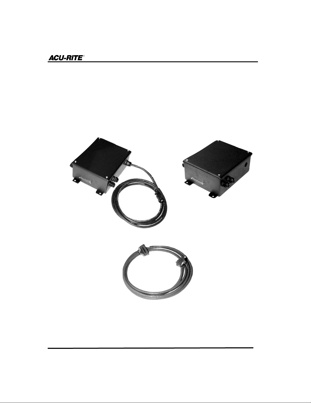
There are two types of AMI systems currently available from ACU-RITE.
One supports 115 volts and the other one supports 230 volts of power. Both
AMIs include a cable for connecting the system to MILLPWR. The 115V AMI
also includes a cord for connecting the system to a
MILLPWR servo motor.
230V AMI
Interface Cable
(included with both
types of AMI)
115V AMI
(includes power cord)
Page 6

AMI Reference Manual
3
AMI System Overview
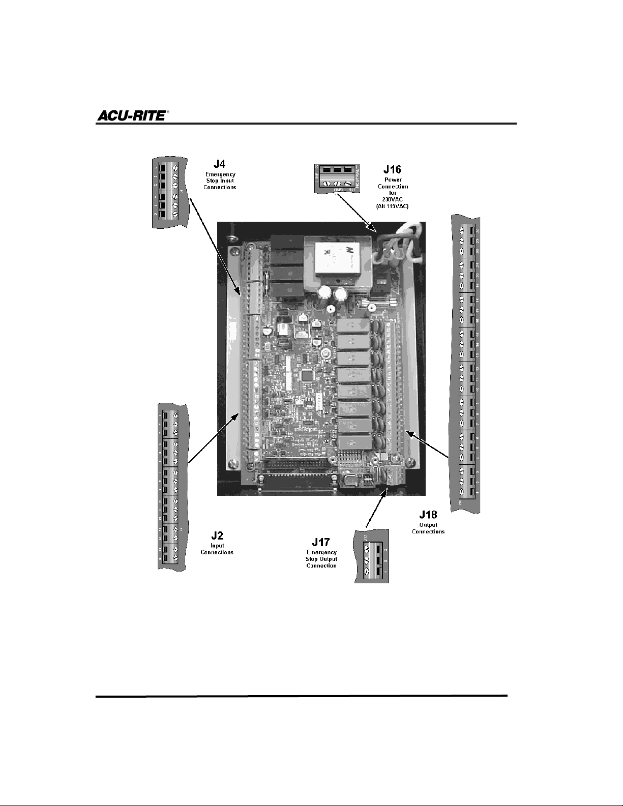
The following is a quick reference guide with each connectors name, the page
where its description appears, and their most common uses. Figure 1 on the next
page shows all connector locations.
There are five connectors available. Four of them are to be used for multiple
applications, while the J16 is limited to wiring an external 230V/115V AMI to a
power source. Always identify the correct connector for your particular application and read its description in its entirety before beginning the wiring procedure.
Device Input J2 (refer to page 5):
• Monitor the position of machine guards
• Monitor the oil level of automatic lubrication systems
• Remote Go Input
Device Output J18 (refer to page 8):
• Control up to four devices (i.e., coolant pumps and rotary indexers)
• Activate external devices during hole patterns and position/drill
steps
Emergency Stop Input J4 (refer to page 13):
• Add table limit switches to the emergency stop circuitry
• Add an emergency stop button to the emergency stop circuitry
Emergency Stop Output J17 (refer to page 16):
• Add other controls to the emergency stop circuitry
Power Input J16 (refer to page 21):
• For use with 230V systems or with an alternate 115V power
source—connects AMI to a power source
Connector Descriptions
Page 7
AMI Reference Manual
4
Fig. 1
Page 8
AMI Reference Manual
5
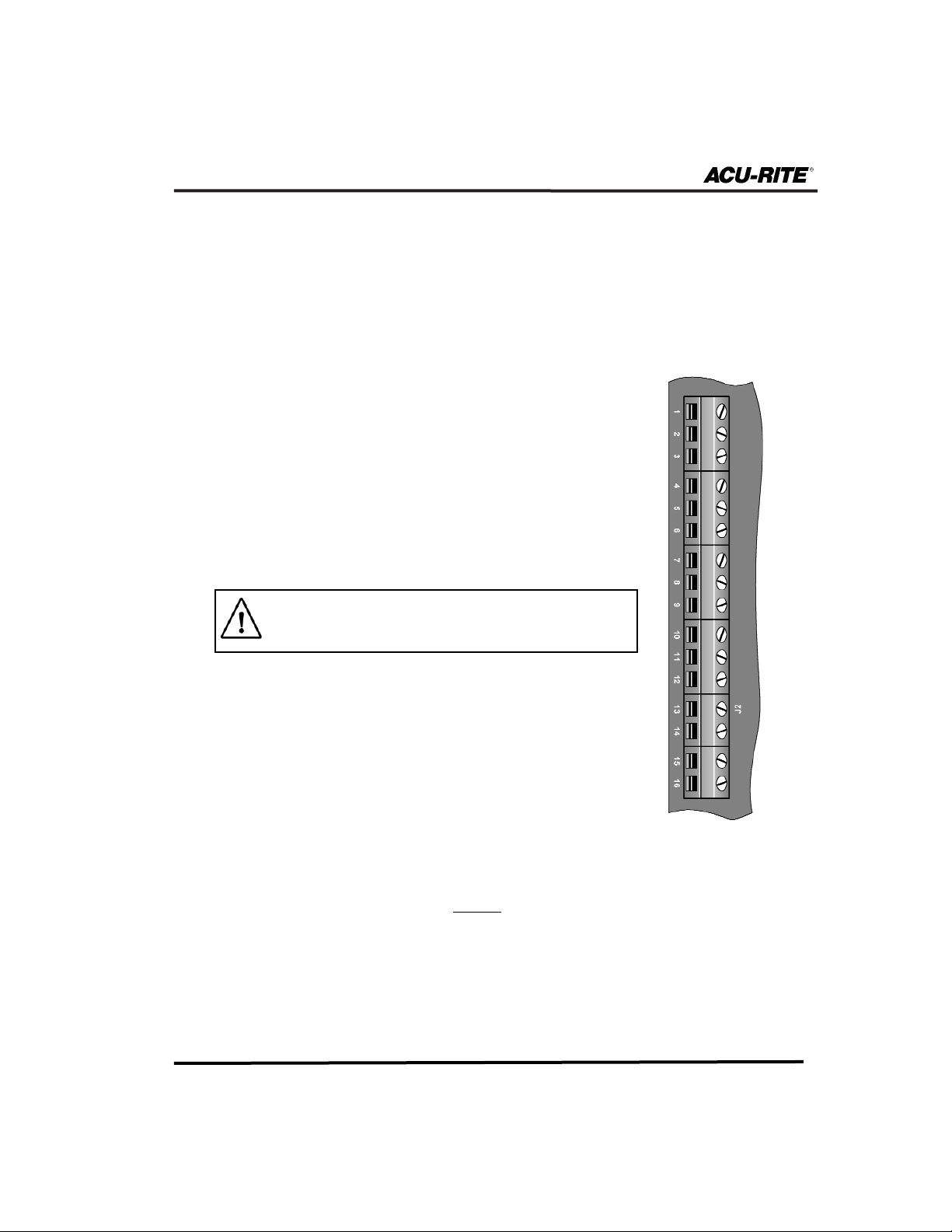
Input Devices (J2)
The J2 input connector is commonly used to:
• Monitor the position of machine guards
• Monitor the oil level of an automatic lubrication system
• Remote Go Input
Do not apply power directly to the AMI
input pins.
Connector Definitions
Machine Guards are safety features that will alter the
activity of certain program functions when they are open.
When guard switches are open:
1) Find Home feature cannot be initiated.
2) Single Cycle cannot be run.
3) A program cannot be run.
4) The table is still able to be moved.
If the guard switches are opened during
these operations:
1) Find Home feature will be aborted.
2) The program currently operating will pause and the table will stop
moving, but the program will not be aborted.
3) Single Cycle will pause.
Table 1 (J2)
Pin #
Description
9
10
11
12
13
14
15
16
Not active
Not active
Not active
Not active
Not active
Not active
Not active
Not active
Pin #
Description
1
2
3
4
5
6
7
8
Machine Guard input
Machine Guard input
Low Oil input
Low Oil input
Remote Go input
Remote Go input
Not active
Not active
Page 9
AMI Reference Manual
6
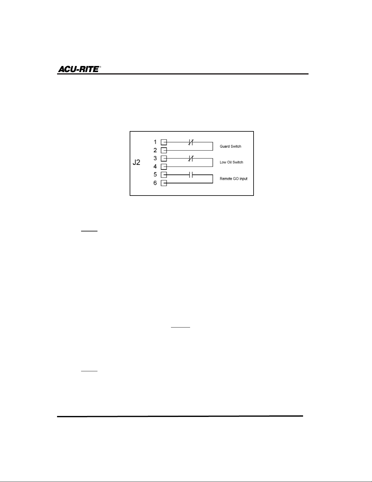
Figure 2 shows a typical wiring diagram for machine guards. As the diagram illustrates, the machine guard switch should be wired to pins 1 and 2.
When the machine guard switches are open, the contacts to those pins will
open, and an Operator Intervention Message (OIM) message will appear on
the MILLPWR screen.
Note:
If guards are not used then pin 1 and pin 2 of J2 must be
jumpered.
Low Oil is a safety feature that will, under certain conditions, stop program
functions when the lubrication pump supply reaches a certain minimum level
of oil. The normally closed low oil switch should be wired to pins 3 and 4.
When the low oil switch opens:
1) Find Home, Move Table, Single Cycle and all program functions
cannot be initiated.
If the low oil feature activates during
these operations:
1) Find Home and Move Table functions will be aborted.
2) Single Cycle and program functions will complete their current
path and then pause.
Note:
If a low oil sensor is not used, then pins 3 and 4 must be
jumpered.
Fig. 2
Page 10
AMI Reference Manual
7
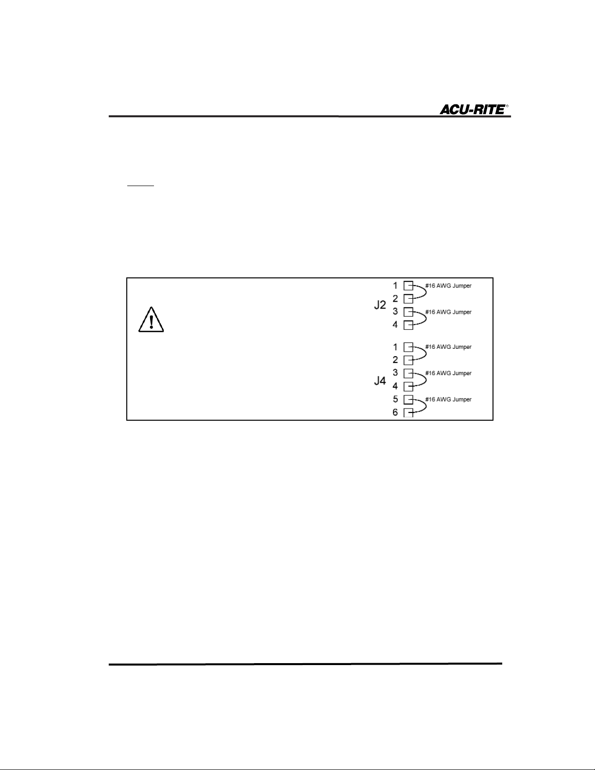
If you are not using the J2 or J4 connec-
tor on the AMI, you must wire a jumper
at this time to close the circuitry.
Otherwise, when you power on
MILLPWR
and the AMI, an emergency stop condi-
tion will automatically occur and
neither system will run.
Remote Go provides a switch input that can be used in place of the operator
pressing the
GO key. Pins 5 and 6 (J2) are reserved for this function.
Note:
The Remote Go input signal must be held for a minimum of
0.2 seconds in either ON or OFF mode in order for it to be recognized by the AMI.
Page 11
AMI Reference Manual
8
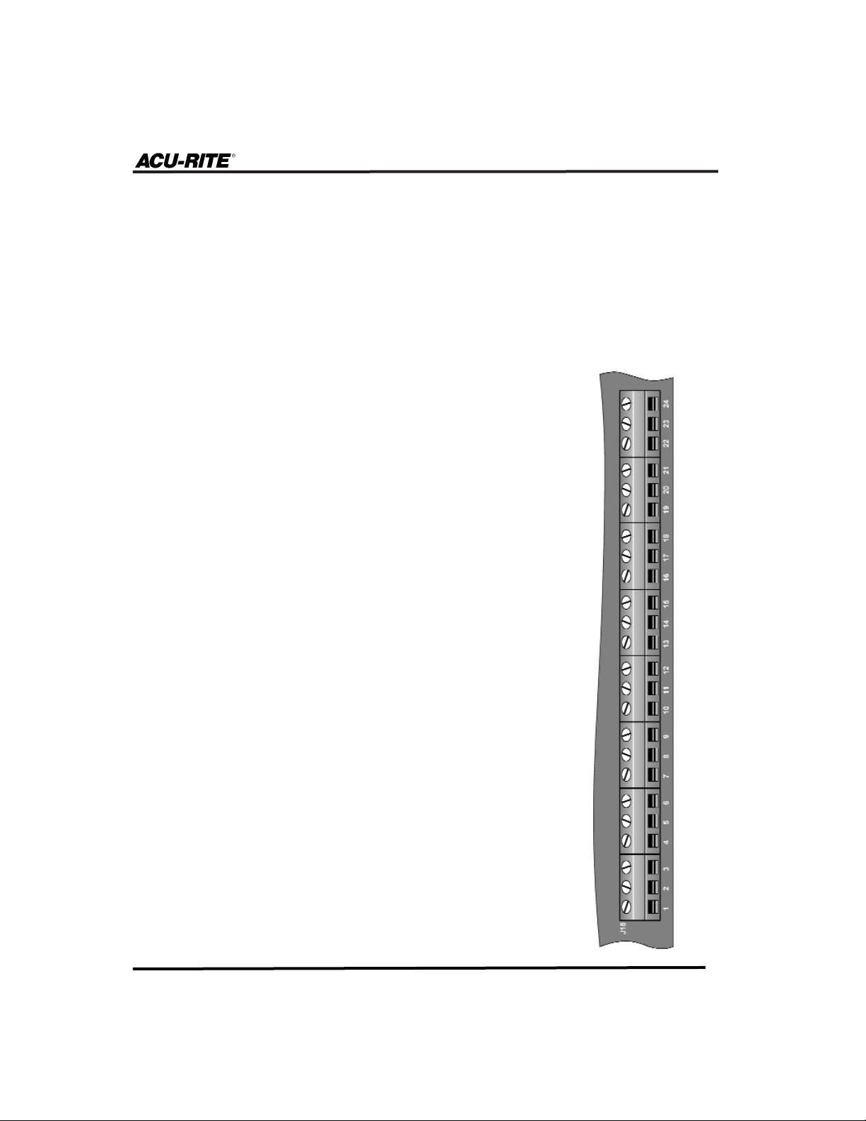
Output Devices (J18)
The J18 output connector is commonly used to:
• Control up to five devices (i.e., coolant pumps and rotary indexers)
from within a MILLPWR program.
• Activate external devices during hole patterns and position/drill
steps.
Common relay contact
Normally Open relay contact
Normally Closed relay contact
Common relay contact
Normally Open relay contact
Normally Closed relay contact
Common relay contact
Normally Open relay contact
Normally Closed relay contact
Common relay contact
Normally Open relay contact
Normally Closed relay contact
Common relay contact
Normally Open relay contact
Normally Closed relay contact
Common relay contact
Normally Open relay contact
Normally Closed relay contact
Common relay contact
Normally Open relay contact
Normally Closed relay contact
Common relay contact
Normally Open relay contact
Normally Closed relay contact
Table 2 (J18)
Pin #
Description
Output Function (Default State)
1
2
3
4
5
6
7
8
9
10
11
12
13
14
15
16
17
18
19
20
21
22
23
24
AMI output #1
AMI output #1
AMI output #1
AMI output #2
AMI output #2
AMI output #2
AMI output #3
AMI output #3
AMI output #3
AMI output #4
AMI output #4
AMI output #4
AMI output #5
AMI output #5
AMI output #5
AMI output #6
AMI output #6
AMI output #6
AMI output #7
AMI output #7
AMI output #7
AMI output #8
AMI output #8
AMI output #8
Normally = Relay de-energized
Page 12

AMI with Spindle Control Reference Manual
9
AMI Output Device Overview
MILLPWR AMI interface allows it to control four (4) separate functions such as
mist and flood coolant, indexers,etc. There are three (3) programmable options
available when programming an AMI step:
• PULSE - Sends a signal to a device for a programmable length of time.
(The pulse duration can not exceed 999.9 seconds).
• ON - Sends a signal until program signals off, or at the completion of
the program.
• OFF - Sends a signal to turn device off.
Each of the signals listed above can be set to display, or not display an
Operator Intervention Message (OIM) at the auxiliary function step.
• NO - Will signal with no OIM. The signal is sent to the device and the
program continues to run. No operator intervention is required.
• BEFORE - Will signal after an OIM. An OIM indicates that pressing
“GO” will activate the programmed device. Pressing “GO” causes the
signal to be sent, and the program continues to run.
• AFTER - Will signal before an OIM. The signal is sent to the device
prior to displaying an OIM. After a signal has been sent, an OIM will
be displayed prompting the operator to press “GO” and the program
continues to run.
Page 13

AMI with Spindle Control Reference Manual
10
Connection Definitions
Auxiliary Outputs 1-4 are four sets of general purpose relay contacts.
1) These relay contacts can only be controlled through a
MILLPWR pro-
gram.
2) They must be set (programmed) to be either ON, OFF or PULSED.
3) Devices programmed to switch “on” will remain “on” for entire program, unless they are programmed to turn “off” later in the program.
4) Devices set to “pulse” will run for the length of time you define (refer
to page 23 for auxiliary function programming).
5) When the program stops, all relays will turn off.
Auxiliary Output 5 - In Position
In-Position. The Auxiliary Machine Interface (AMI) has the ability to send a
signal when
MILLPWR is “in position” for Position Drill steps and Hole pat-
tern steps which require manual Z-axis operation. This is when the table has
moved to either the X, Y coordinates of the position drill step or to each hole
of a hole pattern.
Output #5 (pins 13 through 15) are used for this function.
The In-Position function is configured through the AMI Outputs field under
Installation Setup. This can be set to ON, OFF or PULSED mode.
Note:
For pulsed outputs, the cycle will complete before the program will continue.
Pausing the program won’t affect the auxiliary functions. Each device will
continue to run normally. However,
MILLPWR, will shut off all relays auto-
matically when the program ends. To shut off a device earlier in the program, insert another auxiliary step with the appropriate relay turned off.
Page 14

AMI Reference Manual
11
Here is an example of how the Auxiliary Output functions work in conjunction with a rotary indexer:
1) Use Aux 3, Output #3 as the Cycle Start relay.
2) When the AMI Output #3 relay is pulsed, pins 7 and 8 of J18 are
momentarily shorted for the amount of pulse time entered. This activity
initiates the “Cycle Start” relay in the rotary indexer control, to start a
cycle or step index.
Note:
The pulse time must not exceed the indexer positioning time
to start the next cycle.
3) Once in position, the rotary indexer sends a “Cycle Finish” signal back
to the AMI. The AMI input interprets this as a “GO” signal and performs the next milling operation (Refer to Remote Go on page 7).
This In-Position activity takes place without any outside intervention from
the operator.
G-code Programs
When using a G-code program that requires coolant commands, certain outputs are configured to specific commands (M7, M8, M9). The following rules
apply while running G-code programs:
1) M7 command turns on the Aux 1 as the coolant flood relay.
2) M8 command turns on Aux 2 as the coolant mist relay.
3) M9 turns off both Aux 1 and 2.
4) Only one output, Aux 1 or Aux 2, is permitted to be on at a time.
5) These outputs will be turned On and Off as defined in the G-code
program.
6) Auxiliary outputs 3 and 4 are not used and are always off.
Page 15

AMI with Spindle Control Reference Manual
12
Devices that are connected to auxiliary outputs 1-4 (pins 1 through 12) on the
AMI’s J18 connector are programmable (refer to Table 2). Figure 3 shows
an example of AMI output wiring that would control a pump.
All of the J18 outputs will automatically return to their default settings (refer
to Table 2) any time the Emergency Stop button on the front of the
MILLPWR
operator console is pressed, when an emergency stop input (via J4) occurs or
when the software detects another emergency stop condition.
Fig. 3
Page 16

AMI Reference Manual
13
Emergency Stop Inputs (J4)
The J4 connector is commonly used to:
• Add table limit switches to the emergency stop circuitry
• Add an Emergency Stop button to the emergency stop circuitry
Table 3 (J4)
Pin #
Description
1
2
3
4
5
6
115V (for E-stop relay coil only)
Auxiliary E-stop relay coil (K1)
Auxiliary E-stop relay coil (K1)
AC Common (for E-stop relay coil only)
Table limit switch contact
Table limit switch contact
An emergency stop condition normally occurs when the system overheats, a
fault occurs, or when the Emergency Stop button on the MILLPWR operator
console is pressed. The AMI gives you the option of adding table limit switches and another Emergency Stop button into the system’s emergency stop circuitry. When an emergency stop is activated,
MILLPWR will immediately shut
off the system’s motors, shut off any external devices that are connected to the
AMI, and stop all machine movement.
If you are not using the J2 or J4 connec-
tor on the AMI, you must wire a jumper
at this time to close the circuitry.
Otherwise, when you power on
MILLPWR
and the AMI, an emergency stop condi-
tion will automatically occur and
neither system will run.
Page 17

AMI Reference Manual
14
Fig. 4
Fig. 5
Figure 4 illustrates how a table
limit switch can be wired into the
emergency stop circuitry. Notice that
the switches have been connected to
pins 5 and 6, which are the table
limit switch contacts (refer to Table
3). Because the table limit connections operate on internal 12V DC
power, it’s important to use a table
limit switch with a 12V DC @
100mA minimum rating. Do not
apply voltage directly to pins 5 or
6 on the J4 connector.
Figure 5 shows how an external
Emergency Stop button can use the
AMI circuit board as its power
source (the table limit switches are
shown for completeness). 115V AC
is provided between pins 1 and 4 of
J4 for the internal emergency stop
relay coil.
Figure 6 shows how the external
emergency stop can be wired directly
into an external 115V AC circuit.
When wiring the Emergency Stop button, use a switch with a 115V AC @
100mA minimum rating. (Do not use this circuit to power any external
devices.)
Fig. 6
There are two options for wiring the additional Emergency Stop button. It can be
wired directly to the AMI’s circuit board as a contact closure, or it can be wired
into an external 115V AC system.
Page 18

AMI with Spindle Control Reference Manual
15
Do not use the 115V AC connection for any other circuitry.
Note: If the existing emergency stop system is any other voltage than
115V AC, you must use the AMI as the power source (described
above) for the AMI emergency stop input.
Table Stop Test
The table stop test shows whether or not an emergency stop (E-stop) condition
has been detected or the internal switch has been pressed.
Reports on whether or not the system detects an emergency stop
condition. An E-stop condition can originate from the operator
console, Z-axis, or optional AMI.
Displays the status of the table stop button (Pressed or Released)
on the operator console.
If Z-axis control is enabled, a “Fault” or “No Fault” message
will appear. A fault indicates that at least one of the limit switches on the spindle has been disengaged.
To display the table stop test:
• From the Job Setup screen, select Installation
Setup and press
ENTER. Then select the
Diagnostics screen and press
ENTER again.
• From the Diagnostics screen, highlight Table
Stop Test and press
ENTER. The test will run
automatically.
• When the test is complete, press the EXIT TEST softkey to close the “Table
Stop Test” screen.
• Continue with Diagnostics or press the USE NEW SETTINGS softkey.
E-Stop
Signal
Status
Table Stop
Button
Z-Limit
Page 19

AMI Reference Manual
16
Whenever an “emergency stop” event occurs—such as when the Table Stop
button on the MILLPWR operator console is pressed or the system detects a
fault—MILLPWR will interrupt the milling machine’s movement and all of the
emergency stop outputs will return to their default state (refer to Table 3).
Figure 7 shows an example of how the AMI emergency stop output might
be used to power down a spindle motor when an emergency stop condition
occurs.
Emergency Stop Output (J17)
The emergency stop outputs are not programmable. Do not wire
external devices that you wish to control (pumps, automatic lubrication systems, etc.) directly into
MILLPWR’s emergency stop cir-
cuitry.
The J17 connector is commonly used to:
• Add other devices to the emergency stop circuitry.
Pin #
Description
1
2
3
Normally closed relay contact
Common relay contact
Normally open relay contact
Table 4 (J17)
Fig. 7
Page 20

AMI Reference Manual
17
AMI Installation
The installation procedure is divided into three sections—Connecting to
MILLPWR, General Wiring Procedure, and Connecting to a Power Source.
Refer to the General Wiring Procedure section anytime you are installing a
new input or output device.
Unless indicated otherwise, each section applies to both AMI versions (115V
and 230V).
• Power down the MILLPWR system and disconnect it from its power source.
• Using four (4) 5/16"-18 machine screws, install the AMI in a convenient
location on or near the machine, within close proximity of the
MILLPWR
operator console. Ensure that both the communication cable and the power
cable, for 115V systems, will reach the MILLPWR. If the AMI is being
installed on the machine, check that both are properly grounded. (Use startoothed washers if necessary).
• Connect one end of the interface cable to the connector located on the
AMI (refer to Figure 8). Tighten the two screws on the connector housing.
• Connect the opposite end of the cable to the AMI connector located on the
rear of the
MILLPWR operator console (refer to Figure 9). Tighten the two
screws on the connector housing.
• Proceed to the General Wiring Procedure section (page 18).
All wiring should be performed by a qualified electrician.
Connecting to MILLPWR
Page 21

AMI Reference Manual
18
Fig. 8
Fig. 9
Page 22

AMI Reference Manual
19
General Wiring Procedure
• Check that the MILLPWR system is powered down and disconnected
from its power source. Check that there is no power to the AMI.
• Remove the cover from the AMI.
• Insert a 0.17" to 0.47" diameter cable (with 24 -16 AWG maximum
wires) through the liquid tight strain relief that’s nearest the connector
you are planning to use (refer to Figure 10).
• Tighten the strain relief until the cable is securely in place.
• Cut the cable to length, then strip approximately 3/8” insulation from the
end of each wire.
• Loosen the appropriate connector screws, then insert the wires into
the connectors (refer to Figure 11).
• Tighten the screws. Ensure the wire has been adequately clamped by
applying a slight “tug”.
• After all of the wires are properly connected, reinstall the AMI cover and
insert rubber plugs into the unused holes.
The steps below explain the general procedure for wiring any device to the
connections on the AMI.
Refer to Figure 1 (page 4) for the location of each AMI and Emergency
Stop (E-Stop) input and output connection. Also refer to the AMI System
Overview section for common applications and descriptions of each connection.
All wiring should be performed by a qualified electrician.
Page 23

AMI Reference Manual
20
Fig. 10
Fig. 11
Page 24

AMI Reference Manual
21
• Check that the MILLPWR system is powered down and disconnected from
its power source.
• Locate the last motor assembly in the series of motors connected to the
MILLPWR system.
• Connect the AMI power cable (it should already be attached to the AMI) to
the last motor assembly’s AC connector (refer to Figure 12).
• Twist the black plastic connector clockwise one-half (1/2) turn (You
should feel the connectors “click”).
115V AMI systems:
Fig. 12
Connecting to a Power Source
The AMI’s electrical specifications determine which power source should be
used. If the AMI is set to run at 115V, it can easily be incorporated into the
MILLPWR servo motor power loop. AMIs that are set up for 230V must be con-
nected directly into an existing electrical circuit using a cable with wires that are
24 -16AWG(max.). Carefully follow the instructions for the type of AMI you
are installing.
• Check that:
1) The AMI power cable
and interface cable are
both properly connected.
2) The voltage selector
switch is set at 115V.
3) The correct fuse is
installed (refer to
Electrical Specifications).
AMI
Power
Cable
115V AC Power
Connection
Servo Motor
Servo Motor
Servo Motor
All wiring should be performed by a qualified electrician.
Page 25

AMI with Spindle Control Reference Manual
22
• After all of the inputs/outputs have been properly wired, power up the
MILLPWR system.
230V AMI systems (via the J16 connector):
• Check the
MILLPWR system is powered down and disconnected from its
power source. Check that there is no power to the AMI.
• Remove the cover from the AMI.
• Insert a 0.17” to 0.47” diameter cable (with 24-16 AWG maximum wires)
through the liquid tight strain relief that’s nearest the power connector.
All wiring should be performed by a qualified electrician.
• Tighten the strain relief until the cable is securely in place.
• Cut the cable to length, then remove approximately 3/8” insulation from the
end of each wire.
• Insert the proper wire into the line, ground and neutral inputs on the J16 connector (refer to Figure 13). Tighten the adjacent screws until each wire is
securely in place.
• Check that:
1) The AMI power cable and interface cable are both properly connected.
2) The voltage selector switch is set at 230V.
3) The correct fuse is installed (refer to Electrical Specifications located at
the end of this manual).
• Reinstall the cover onto the AMI. Insert rubber plugs into the unused holes.
• After all of the inputs/outputs have been properly wired, power up the
MILLPWR system.
Page 26

AMI with Spindle Control Reference Manual
23
Fig. 13
J16
Connectors
Page 27

AMI Reference Manual
24
Programming Auxiliary Output Devices Wired
to J18 (Aux 1-4)
Devices that are connected to pins 1 through 12 of the AMI’s J18 output
connector can be controlled from within any MILLPWR part program.
Simply insert an auxiliary function step at each point in the program
where you want the appropriate device to turn on, off or pulse.
When
MILLPWR reaches an auxiliary function step, an Operator
Intervention Message (OIM) will appear. The OIM will display the status
for each device. Press the
GO key to activate the relays and continue run-
ning the program.
Pausing the program won't affect the auxiliary functions. Each device will
continue to run normally; however,
MILLPWR will shut off all of the
relays automatically when the program ends. To shut off a device earlier
in the program, insert another auxiliary step with the appropriate relay
turned "off."
Devices programmed to switch "on" will run continuously as you
machine; devices set to "pulse" will run for the length of time that you
define.
Modes of Operation
Using Auxiliaries 1-4
• First, check that each device is connected to the Auxiliary outputs
(1-4) of J18, located on the AMI.
• From the PGM screen, highlight a step within the program where
you want to add or insert an auxiliary function step.
• Press the MORE STEPS softkey.
AMI Operation
Page 28

AMI Reference Manual
25
• Press the MORE STEPS softkey two more times.
• Press the AUXILIARY FUNCTIONS softkey.
• Highlight the auxiliary relay(s) that you want to
program. (The “AUX” numbers in each field correspond with the number on the AMI.) Select
from the OFF, ON, and PULSED softkeys for each.
ON The AMI output contacts will
switch to an energized state.
OFF The AMI output contacts will
switch to their default (de-energized) states.
PULSED The AMI output contacts will
switch to an energized state for
the length of time that you define.
Display User Prompt The AMI allows the operator, if desired,
to pause the step before or after the
relays are turned on or off.
• If you selected PULSED, then enter the amount of time (in seconds or
tenths of seconds) that you want the relay to remain on. The maximum
amount of time that a relay can pulse is 999.9 seconds.
Note:
Pulse mode must time out before the steps of the program can
continue.
• Set the Display User Prompt for the step to pause before or after by
pressing either the BEFORE STEP, AFTER STEP. If you choose not to
include a pause, press the NO softkey.
Note:
The auxiliary function relays will not turn off automatically
during an Operator Intervention Message (OIM).
• Pressing YES for the Set Continuous field allows an Auxiliary Function
Step to be entered (e.g. activate coolant) without interrupting the continuous milling path.
• Press the
USE key.
Page 29

AMI Reference Manual
26
G-code Programs
When using a G-code program that requires coolant commands, certain
outputs are configured to specific commands (M7, M8, M9). The following
rules apply while running G-code programs:
1) M7 command turns on the Aux 1 as the coolant flood relay.
2) M8 command turns on Aux 2 as the coolant mist relay.
3) M9 turns off both Auxs 1 and 2.
4) Only one output, Aux 1 or Aux 2, is permitted to be on at a time.
5) These outputs will be turned On and Off as defined in the G-code
program.
6) Auxiliary outputs 3 and 4 are not used and are always off.
Page 30

AMI Reference Manual
27
Using the In-Position Relay
• Press the
SETUP key.
• From the Installation Setup menu, cursor
down to the AMI Outputs field and press
the
ENTER key.
• Along the bottom of the screen the OFF, ON and PULSED softkeys will
also appear.
If ON is selected, the output will be asserted when the desired X/Y
position is reached and will remain on until the X and Y positions
have moved out of position.
If PULSED is selected, the desired pulse time must be entered in seconds. (Time may be entered to tenths of a second.) The In-Position
relay will remain energized when in position and will be de-energized
when the programmed time has elapsed or program step execution is
completed or aborted.
• To save an In-Position configuration, press the USE or the USE NEW
SETTINGS softkey.
Note:
Check that the devices you are using are powered on before
running the program.
Page 31

AMI with Spindle Control Reference Manual
28
Motor Assembly Monitor
When the motor assembly monitor is enabled, it shows the real-time operating status of each axis and the AMI on the DRO screen. Use it to verify the
status of all AMI inputs and outputs.
Reports on the AC power status (On or Off); also reports
system failures and emergency stop conditions when they
occur.
Displays the table’s incremental position (its position relative
to incremental zero).
Displays the table’s absolute position (its position relative to
datum).
Reports on each motor’s operating status (On, Off, Not
Present or Fault).
Shows the internal air temperature for each motor.
Temperatures should not exceed 75° C.
Monitors the DC motor current voltage. An "X" after the
value indicates that the voltage inrush bypass circuit is
active. It can also be seen when the E-Stop button is pressed
and then released. The “X” should disappear within 2 - 3
seconds after the system is powered up.
Top Bar
(Power
Status)
INC
ABS
Status
Temp
Current
Page 32

AMI with Spindle Control Reference Manual
29
T
o enable or disable the motor assembly monitor:
• From the Job Setup screen, select Installation Setup and press ENTER,
enter the passcode. Select the Diagnostics screen and press
ENTER
again
.
• From the Diagnostics screen, highlight Motor Assembly Monitor and
press
ENTER.
• Press either the ENABLED or DISABLED softkey. (If the ENABLED
softkey is selected, the Motor Assembly Monitor display will appear on
the DRO screen.)
• Press the
USE key.
• Continue with Diagnostics or press the USE NEW SETTINGS softkey.
Safety feature that will alter the activity of certain program
functions when they are open.
Safety feature that will, under certain conditions, stop program functions when the lubrication pump supply reaches a
certain minimum level of oil.
Provides a switch input that can be used in place of the
operator pressing the
GO key or the remote Stop/Go switch.
Guards
Closed
Oil Not
Low
No Go Key
Page 33

AMI Reference Manual
30
Symptom
Probable Cause
Recommended
Corrective
Action
No operation or
improper operation
Loose interface cable
No power or incorrect
voltage to AMI
Incorrect voltage setting
Check that the cable is
properly connected to
MILLPWR and that the
screws are secure.
Check that the AMI
is wired at the correct voltage. Also ensure that the
power cables for the
motors are properly daisychained to the
MILLPWR
operator console (refer to
Connecting to a Power
Source, page 20).
Verify that the voltage
selector switch is set correctly—at 115 for 115
volt operation; at 220 for
220 volt operation.
Ribbon connector to J14
is loose (European AMIs
only)
Check the connection.
Tighten or reconnect it as
needed.
AMI Troubleshooting Guide
This troubleshooting guide is arranged in three columns—Symptom, Probable
Cause and Recommended Corrective Action. Begin by locating the symptom
and probable cause that best matches the problem you are experiencing, then follow the directions for each corrective action.
If the suggestions herein do not solve the problem, contact ACU-RITE for repair
and/or replacement procedures.
Page 34

AMI Reference Manual
31
Symptom
Probable Cause
Recommended
Corrective
Action
Improper wiring
Ensure stripped end of the
wire is adequately crimped
by the terminal on the
board (vs. insulation being
crimped).
F3 fuse is loose Check that the F3 fuse is
securely in place.
F3 fuse is blown
Replace the F3 fuse with
one that’s appropriate for
the AMI operation (refer to
Electrical Specifications).
External
emergency stop
button does not
work
Improper voltage
If circuit is wired using
external power, ensure
120VAC (+/- 10%) is being
used.
F1 fuse is blown
Contact ACU-RITE for
repair procedure.
No operation or
improper operation
(cont’d)
Page 35

AMI Reference Manual
32
Symptom
Probable Cause
Recommended
Corrective Action
Machine guards
and low oil messages are reversed
Improper wiring Check the wiring to the
AMI’s J2 connector. The
machine guard switch
should be wired to pins 1
and 2, and the auto lube
system should be wired
to pins 3 and 4 (refer to
Input Devices (J2)).
Table limit switches do not work
Improper wiring
Verify that the wires are
connected to pins 5 and 6
on the AMI’s J4 connector (refer to Emergency
Stop Inputs).
Emergency stop
message is constantly displayed
on MILLPWR operator console.
No External E-Stop is
wired to the J4 connector,
or it may be done so
incorrectly.
This input must be configured. Either connect
an external emergency
stop switch to J4, or use
a wire jumper to defeat
it.
Page 36

AMI Reference Manual
33
Symptom
Probable Cause
Recommended
Corrective Action
No response to oil
or guard switches
Loose interface cable
Check that the interface
cable is properly connected to
MILLPWR and
that the screws are
secure.
"External E-Stop"
and "Table Limits"
messages are
reversed
Incorrect wiring
Verify that the proper
wires are connected to
pins 5 and 6 on the J4
connector (refer to
Emergency Stop
Inputs).
Table limit switches do not work
(cont’d)
Improper wiring (cont’d) Ensure that all of the
table limit switches are
normally closed and
wired in series.
If more than one table
limit switch exists, verify
that they are “normally
closed” and wired in
series.
Improper wiring
Check that the switches
are properly wired to the
J2 connector. The
machine guard switch
should be wired to pins 1
and 2, and the auto lube
system should be wired
to pins 3 and 4 (refer to
Input Devices (J2)).
Page 37

AMI Reference Manual
34
Output devices not
responding/not
responding properly
AMI is not receiving
power.
Check that the AMI is
receiving power (also
refer to probable causes
and corrective actions
under “No operation or
improper operation,”
page 29).
No response to oil
or guards switches
(cont’d)
Symptom
Probable Cause
Recommended
Corrective
Action
Ensure that all of the
wires are secure beneath
the screw(s) on the J2
connector. Disconnect
power to
MILLPWR and
the AMI. Completely
loosen each screw on the
connector. One by one,
reinsert each wire into
the connector, under the
body of the screw.
Tightening each screw as
you do so.
Improper wiring (cont’d)
Page 38

AMI Reference Manual
35
Improper wiring
Compare the wiring to
the "normally closed"
and "normally open" contacts for that connector,
as described in the manual. Rewire as needed.
Symptom
Probable Cause
Recommended
Corrective Action
Each wire must be
secured under the corresponding screw.
Disconnect power to
MILLPWR and the AMI.
Completely loosen each
screw on the connector.
Reinsert each wire one
by one, retightening each
screw as you do so.
One or more wires not
secure in the J2 connector
Output devices not
responding/not
responding properly (cont’d)
Output not functioning
correctly
Check the auxiliary function steps within the program and verify that the
information in each step
is correct.
Page 39

AMI Reference Manual
36
Characteristic Specification
Operating conditions
0° to 40° C (32° to 104° F)
25% to 85% relative humidity (non-condensing)
Storage conditions
-20° to 60° C (-4° to 140° F)
25% to 95% relative humidity (non-condensing)
115VAC ±10%
230VAC ±10%
47-63Hz
124mA (max.) @ 115VAC
62mA (max.) @ 230VAC
Input requirements:
Voltage
Frequency
Current
Fuse
200mA, 3AG, 250V SLO-BLO @ 115VAC
100mA, 3AG, 250V SLO-BLO @ 230VAC
4 Amps max. @ 230V AC
AMI output relay
contact ratings (J18)
FCC compliance
Part 15 of FCC rules for a class A
computing device
Compatibility
Compatible with ACU-RITE
®
MILLPWR
®
systems software versions 2.1.2 and 3.1.2 or later
Electrical Specifications
The installation location must be able to support the AMI operating and
electrical requirements listed below.
E-Stop Output ratings (J17)
14 Amps max. @ 230V AC
SCI Contact Specifications
(J1, J2 & J5)
0.5 Amps max @ 125V AC
Page 40

ACU-RITE INCORPORATED
One Precision Way • Jamestown, NY 14701
ACU-RITE IS AN
ISO 9001
CERTIFIED
MANUFACTURER
fi
 Loading...