

Page 1

MILLPWR Setup Access Code
An access code must be entered before the installation setup
parameters can be accessed or changed.
Refer to Section 7, Setup.
The access code is 8891.
Supervisors may wish to remove this page from the MILLPWR
Operation Manual after initially setting up the installation setup
parameters. Keep it in a safe place for future use.
IMPORTANT
IMPORTANT
Page 2

TABLE OF CONTENTS
MILLPWR
®
Operation Manual
Introduction . . . . . . . . . . . . . . . . . . . . . . . . . . . . . . . . . . . . . . . . . . . . . . . . . .1-1
System Overview . . . . . . . . . . . . . . . . . . . . . . . . . . . . . . . . . . . . . . . . . . .1-1
Operator Console Overview . . . . . . . . . . . . . . . . . . . . . . . . . . . . . . . .1-2
Keypad Layout . . . . . . . . . . . . . . . . . . . . . . . . . . . . . . . . . . . . . . . . .1-3
Screen Layout . . . . . . . . . . . . . . . . . . . . . . . . . . . . . . . . . . . . . . . . . .1-4
Table Stop Button . . . . . . . . . . . . . . . . . . . . . . . . . . . . . . . . . . . . . . .1-5
Conventions . . . . . . . . . . . . . . . . . . . . . . . . . . . . . . . . . . . . . . . . . . . . . .1-5
Axis Conventions . . . . . . . . . . . . . . . . . . . . . . . . . . . . . . . . . . . . . . . .1-5
Count Direction . . . . . . . . . . . . . . . . . . . . . . . . . . . . . . . . . . . . . .1-5
Cartesian Coordinates . . . . . . . . . . . . . . . . . . . . . . . . . . . . . . . . . . . . .1-6
Polar Coordinates . . . . . . . . . . . . . . . . . . . . . . . . . . . . . . . . . . . . . . . .1-6
Absolute and Incremental Dimensions . . . . . . . . . . . . . . . . . . . . . . . .1-7
Saving, Backing Up, and Creating Directories . . . . . . . . . . . . . . . . . .1-8
DRO . . . . . . . . . . . . . . . . . . . . . . . . . . . . . . . . . . . . . . . . . . . . . . . . . . . . . . . . .2-1
Start Up . . . . . . . . . . . . . . . . . . . . . . . . . . . . . . . . . . . . . . . . . . . . . . . . . .2-1
Power Up . . . . . . . . . . . . . . . . . . . . . . . . . . . . . . . . . . . . . . . . . . . . . .2-1
Screen Saver . . . . . . . . . . . . . . . . . . . . . . . . . . . . . . . . . . . . . . . . . . . .2-1
Finding Home . . . . . . . . . . . . . . . . . . . . . . . . . . . . . . . . . . . . . . . . . .2-2
DRO Functions . . . . . . . . . . . . . . . . . . . . . . . . . . . . . . . . . . . . . . . . . . . .2-3
Move Table . . . . . . . . . . . . . . . . . . . . . . . . . . . . . . . . . . . . . . . . . . . .2-3
Teach Position . . . . . . . . . . . . . . . . . . . . . . . . . . . . . . . . . . . . . . . . . .2-4
Using an Electronic Edge Finder . . . . . . . . . . . . . . . . . . . . . . . . . . . .2-5
Skewing a Part . . . . . . . . . . . . . . . . . . . . . . . . . . . . . . . . . . . . . . . . . .2-6
Establishing Datum . . . . . . . . . . . . . . . . . . . . . . . . . . . . . . . . . . . . . .2-8
Hard Key Milling Functions . . . . . . . . . . . . . . . . . . . . . . . . . . . . . . .2-11
Programming . . . . . . . . . . . . . . . . . . . . . . . . . . . . . . . . . . . . . . . . . . . . . . . . .3-1
Programming Considerations . . . . . . . . . . . . . . . . . . . . . . . . . . . . . . . . . .3-1
"From" and "To" Points . . . . . . . . . . . . . . . . . . . . . . . . . . . . . . . . . . .3-1
Depth of Cut . . . . . . . . . . . . . . . . . . . . . . . . . . . . . . . . . . . . . . . . . . .3-1
Tool Offset . . . . . . . . . . . . . . . . . . . . . . . . . . . . . . . . . . . . . . . . . . . . .3-1
Datum Selection . . . . . . . . . . . . . . . . . . . . . . . . . . . . . . . . . . . . . . . .3-2
Absolute and Incremental Dimensions . . . . . . . . . . . . . . . . . . . . . . . .3-2
Continuous Milling . . . . . . . . . . . . . . . . . . . . . . . . . . . . . . . . . . . . . .3-3
Creating a Program . . . . . . . . . . . . . . . . . . . . . . . . . . . . . . . . . . . . . . . . .3-4
The View Key . . . . . . . . . . . . . . . . . . . . . . . . . . . . . . . . . . . . . . . . . .3-6
Follow Tool . . . . . . . . . . . . . . . . . . . . . . . . . . . . . . . . . . . . . . . . . .3-6
Show Tool Path . . . . . . . . . . . . . . . . . . . . . . . . . . . . . . . . . . . . . . .3-6
Zoom In, Zoom Out and Restore . . . . . . . . . . . . . . . . . . . . . . . . . .3-6
i
Page 3

TABLE OF CONTENTS
MILLPWR
®
Running a Program . . . . . . . . . . . . . . . . . . . . . . . . . . . . . . . . . . . . . . . . .3-7
Skewing a Part . . . . . . . . . . . . . . . . . . . . . . . . . . . . . . . . . . . . . . . . . .3-7
Establishing Datum . . . . . . . . . . . . . . . . . . . . . . . . . . . . . . . . . . . . . .3-9
Testing Your Program . . . . . . . . . . . . . . . . . . . . . . . . . . . . . . . . . . . .3-12
Single Step . . . . . . . . . . . . . . . . . . . . . . . . . . . . . . . . . . . . . . . . . .3-12
Dry Run . . . . . . . . . . . . . . . . . . . . . . . . . . . . . . . . . . . . . . . . . . . .3-12
Graphics Only . . . . . . . . . . . . . . . . . . . . . . . . . . . . . . . . . . . . . . . .3-12
Manual Positioning . . . . . . . . . . . . . . . . . . . . . . . . . . . . . . . . . . . .3-13
Disable Look Ahead . . . . . . . . . . . . . . . . . . . . . . . . . . . . . . . . . . .3-13
Pressing the GO Key . . . . . . . . . . . . . . . . . . . . . . . . . . . . . . . . . . . . .3-14
Feed + and Feed - . . . . . . . . . . . . . . . . . . . . . . . . . . . . . . . . . . . . . . .3-15
Machining to Zero . . . . . . . . . . . . . . . . . . . . . . . . . . . . . . . . . . . . . . .3-16
Program Functions . . . . . . . . . . . . . . . . . . . . . . . . . . . . . . . . . . . . . . . . . .3-17
Accessing the Load, Save, Delete, Merge Backup and
Directory Options . . . . . . . . . . . . . . . . . . . . . . . . . . . . . . . . . . . . .3-17
Directories . . . . . . . . . . . . . . . . . . . . . . . . . . . . . . . . . . . . . . . . . . . . .3-18
Creating a Subdirectory . . . . . . . . . . . . . . . . . . . . . . . . . . . . . . . .3-19
Selecting a Directory . . . . . . . . . . . . . . . . . . . . . . . . . . . . . . . . . .3-21
Deleting a Directory . . . . . . . . . . . . . . . . . . . . . . . . . . . . . . . . . . .3-23
Saving a Program . . . . . . . . . . . . . . . . . . . . . . . . . . . . . . . . . . . . . . . .3-24
Naming a Program . . . . . . . . . . . . . . . . . . . . . . . . . . . . . . . . . . . . . . .3-25
Loading a
MILLPWR (MPT) Program . . . . . . . . . . . . . . . . . . . . . . . .3-26
From
MILLPWR's internal memory . . . . . . . . . . . . . . . . . . . . . . . . .3-26
From a 3
1
/2" floppy disk . . . . . . . . . . . . . . . . . . . . . . . . . . . . . . . .3-27
From your PC . . . . . . . . . . . . . . . . . . . . . . . . . . . . . . . . . . . . . . .3-28
Translating a DXF file . . . . . . . . . . . . . . . . . . . . . . . . . . . . . . . . . . . .3-28
Loading a G-code file . . . . . . . . . . . . . . . . . . . . . . . . . . . . . . . . . . . . .3-29
Running a G-code Program . . . . . . . . . . . . . . . . . . . . . . . . . . . . . . . . .3-31
MILLPWR G-code Conventions . . . . . . . . . . . . . . . . . . . . . . . . . . . . . . . . .3-33
Merging Programs . . . . . . . . . . . . . . . . . . . . . . . . . . . . . . . . . . . . . . .3-37
Backing Up a Program . . . . . . . . . . . . . . . . . . . . . . . . . . . . . . . . . . . .3-38
Deleting a Program . . . . . . . . . . . . . . . . . . . . . . . . . . . . . . . . . . . . . .3-39
Demonstration Program . . . . . . . . . . . . . . . . . . . . . . . . . . . . . . . . . . . . . . .4-1
Selecting Datum . . . . . . . . . . . . . . . . . . . . . . . . . . . . . . . . . . . . . . . . . . .4-1
Beginning the Program . . . . . . . . . . . . . . . . . . . . . . . . . . . . . . . . . . . . . .4-2
Selecting a Tool . . . . . . . . . . . . . . . . . . . . . . . . . . . . . . . . . . . . . . . . .4-2
Programming the Contour . . . . . . . . . . . . . . . . . . . . . . . . . . . . . . . . .4-4
Programming the Bolthole Pattern . . . . . . . . . . . . . . . . . . . . . . . . . . .4-12
Programming the Rectangular Pocket . . . . . . . . . . . . . . . . . . . . . . . . .4-15
Saving Your Program . . . . . . . . . . . . . . . . . . . . . . . . . . . . . . . . . . . . . . . .4-17
Testing Your Program . . . . . . . . . . . . . . . . . . . . . . . . . . . . . . . . . . . . . . .4-18
Operation Manual
ii
Page 4

TABLE OF CONTENTS
MILLPWR
®
Operation Manual
Running the Program . . . . . . . . . . . . . . . . . . . . . . . . . . . . . . . . . . . . . . . .4-19
Tool Changes . . . . . . . . . . . . . . . . . . . . . . . . . . . . . . . . . . . . . . . . . . . . . .4-20
Clearing the Program . . . . . . . . . . . . . . . . . . . . . . . . . . . . . . . . . . . . . . . .4-20
Program Steps . . . . . . . . . . . . . . . . . . . . . . . . . . . . . . . . . . . . . . . . . . . . . . . .5-1
Simple Milling and Drilling . . . . . . . . . . . . . . . . . . . . . . . . . . . . . . . . . . .5-1
Set Tool . . . . . . . . . . . . . . . . . . . . . . . . . . . . . . . . . . . . . . . . . . . . . . .5-1
Programming a Tool Step w/Repeatable Tool Length Offsets . . . . . . . . . .5-2
Entering the First Tool . . . . . . . . . . . . . . . . . . . . . . . . . . . . . . . . . . . .5-2
Changing to a Tool of Unknown Length in the DRO . . . . . . . . . . . . . .5-4
Changing to a Tool Of Unknown Length in PGM . . . . . . . . . . . . . . . .5-4
Position/Drill . . . . . . . . . . . . . . . . . . . . . . . . . . . . . . . . . . . . . . . . . . .5-6
Center Line . . . . . . . . . . . . . . . . . . . . . . . . . . . . . . . . . . . . . . . . . .5-6
Line . . . . . . . . . . . . . . . . . . . . . . . . . . . . . . . . . . . . . . . . . . . . . . .5-7
Arc . . . . . . . . . . . . . . . . . . . . . . . . . . . . . . . . . . . . . . . . . . . . . . . .5-8
Blend . . . . . . . . . . . . . . . . . . . . . . . . . . . . . . . . . . . . . . . . . . . . . .5-10
Rectangular Milling Functions . . . . . . . . . . . . . . . . . . . . . . . . . . . . . . . . .5-12
Pocket . . . . . . . . . . . . . . . . . . . . . . . . . . . . . . . . . . . . . . . . . . . . . . . . .5-12
Frame . . . . . . . . . . . . . . . . . . . . . . . . . . . . . . . . . . . . . . . . . . . . . . . . .5-15
Face . . . . . . . . . . . . . . . . . . . . . . . . . . . . . . . . . . . . . . . . . . . . . . . . . .5-17
Slot . . . . . . . . . . . . . . . . . . . . . . . . . . . . . . . . . . . . . . . . . . . . . . . . . . .5-19
Circular Milling Functions . . . . . . . . . . . . . . . . . . . . . . . . . . . . . . . . . . . .5-21
Pocket . . . . . . . . . . . . . . . . . . . . . . . . . . . . . . . . . . . . . . . . . . . . . . . . .5-21
Frame . . . . . . . . . . . . . . . . . . . . . . . . . . . . . . . . . . . . . . . . . . . . . . . . .5-23
Ring . . . . . . . . . . . . . . . . . . . . . . . . . . . . . . . . . . . . . . . . . . . . . . . . . .5-25
Hole Patterns . . . . . . . . . . . . . . . . . . . . . . . . . . . . . . . . . . . . . . . . . . . . . .5-27
Row of Holes . . . . . . . . . . . . . . . . . . . . . . . . . . . . . . . . . . . . . . . . . . .5-27
Hole Frame and Hole Array . . . . . . . . . . . . . . . . . . . . . . . . . . . . . . . .5-29
Bolthole Circle Patterns . . . . . . . . . . . . . . . . . . . . . . . . . . . . . . . . . . .5-31
Additional Milling Functions . . . . . . . . . . . . . . . . . . . . . . . . . . . . . . . . . .5-33
Custom Pocket . . . . . . . . . . . . . . . . . . . . . . . . . . . . . . . . . . . . . . . . . .5-33
Repeat . . . . . . . . . . . . . . . . . . . . . . . . . . . . . . . . . . . . . . . . . . . . . . . .5-35
Rotate . . . . . . . . . . . . . . . . . . . . . . . . . . . . . . . . . . . . . . . . . . . . . . . . .5-36
Mirror . . . . . . . . . . . . . . . . . . . . . . . . . . . . . . . . . . . . . . . . . . . . . . . . .5-37
Contour . . . . . . . . . . . . . . . . . . . . . . . . . . . . . . . . . . . . . . . . . . . . . . . .5-38
Engrave . . . . . . . . . . . . . . . . . . . . . . . . . . . . . . . . . . . . . . . . . . . . . . .5-40
Engrave Line . . . . . . . . . . . . . . . . . . . . . . . . . . . . . . . . . . . . . . . . .5-40
Engrave Arc . . . . . . . . . . . . . . . . . . . . . . . . . . . . . . . . . . . . . . . . .5-43
Ellipse Frame . . . . . . . . . . . . . . . . . . . . . . . . . . . . . . . . . . . . . . . . . . .5-45
Chamfer . . . . . . . . . . . . . . . . . . . . . . . . . . . . . . . . . . . . . . . . . . . . . . .5-47
Reference Point . . . . . . . . . . . . . . . . . . . . . . . . . . . . . . . . . . . . . . . . . .5-49
iii
Page 5

TABLE OF CONTENTS
MILLPWR
®
Island . . . . . . . . . . . . . . . . . . . . . . . . . . . . . . . . . . . . . . . . . . . . . . . . .5-50
Spiral . . . . . . . . . . . . . . . . . . . . . . . . . . . . . . . . . . . . . . . . . . . . . . . . .5-52
Comment Step . . . . . . . . . . . . . . . . . . . . . . . . . . . . . . . . . . . . . . . . . .5-54
Auxiliary Function (AMI Option) . . . . . . . . . . . . . . . . . . . . . . . . . . . .5-55
Step Functions . . . . . . . . . . . . . . . . . . . . . . . . . . . . . . . . . . . . . . . . . . . . .5-57
Explode . . . . . . . . . . . . . . . . . . . . . . . . . . . . . . . . . . . . . . . . . . . . . . .5-57
Reverse Step . . . . . . . . . . . . . . . . . . . . . . . . . . . . . . . . . . . . . . . . . . . .5-59
Reverse Path . . . . . . . . . . . . . . . . . . . . . . . . . . . . . . . . . . . . . . . . . . . .5-59
Change Steps . . . . . . . . . . . . . . . . . . . . . . . . . . . . . . . . . . . . . . . . . . .5-60
Delete Steps . . . . . . . . . . . . . . . . . . . . . . . . . . . . . . . . . . . . . . . . . . . .5-61
Copy/Move Steps . . . . . . . . . . . . . . . . . . . . . . . . . . . . . . . . . . . . . . . .5-62
Calculator . . . . . . . . . . . . . . . . . . . . . . . . . . . . . . . . . . . . . . . . . . . . . . . . . . . .6-1
Math Functions (+, -, x, ÷) . . . . . . . . . . . . . . . . . . . . . . . . . . . . . . . . . . . .6-2
Trig Functions . . . . . . . . . . . . . . . . . . . . . . . . . . . . . . . . . . . . . . . . . . . . .6-2
Geometry Functions . . . . . . . . . . . . . . . . . . . . . . . . . . . . . . . . . . . . . . . .6-4
Working with the Geometry Calculator . . . . . . . . . . . . . . . . . . . . . . .6-4
Calculator Functions . . . . . . . . . . . . . . . . . . . . . . . . . . . . . . . . . . . . . .6-7
Saving Results Calculated in GeoCalc . . . . . . . . . . . . . . . . . . . . . .6-7
Loading GeoCalc Results . . . . . . . . . . . . . . . . . . . . . . . . . . . . . . .6-8
Loading Programs into GeoCalc . . . . . . . . . . . . . . . . . . . . . . . . . .6-9
Clearing GeoCalc . . . . . . . . . . . . . . . . . . . . . . . . . . . . . . . . . . . . .6-9
Example Problem . . . . . . . . . . . . . . . . . . . . . . . . . . . . . . . . . . . . . . . .6-10
Strategy . . . . . . . . . . . . . . . . . . . . . . . . . . . . . . . . . . . . . . . . . . . .6-10
Starting the Program . . . . . . . . . . . . . . . . . . . . . . . . . . . . . . . . . .6-11
Entering the Lines . . . . . . . . . . . . . . . . . . . . . . . . . . . . . . . . .6-11
Finding the Arc . . . . . . . . . . . . . . . . . . . . . . . . . . . . . . . . . . .6-14
Finding the Points of Tangency . . . . . . . . . . . . . . . . . . . . . . . .6-15
Returning Features . . . . . . . . . . . . . . . . . . . . . . . . . . . . . . . . .6-16
RPM Functions . . . . . . . . . . . . . . . . . . . . . . . . . . . . . . . . . . . . . . . . . . . . .6-18
Setup . . . . . . . . . . . . . . . . . . . . . . . . . . . . . . . . . . . . . . . . . . . . . . . . . . . . . . . . .7-1
Overview . . . . . . . . . . . . . . . . . . . . . . . . . . . . . . . . . . . . . . . . . . . . . . . . .7-1
Job Setup . . . . . . . . . . . . . . . . . . . . . . . . . . . . . . . . . . . . . . . . . . . . . . . . .7-2
Tool Library . . . . . . . . . . . . . . . . . . . . . . . . . . . . . . . . . . . . . . . . . . . .7-2
Using the Tool Library with Repeatable Tool Length Offsets . . . . . . . . . .7-4
Entering the First Tool . . . . . . . . . . . . . . . . . . . . . . . . . . . . . . . . . .7-5
Using the Tool Library . . . . . . . . . . . . . . . . . . . . . . . . . . . . . . . . .7-7
Scale Factor . . . . . . . . . . . . . . . . . . . . . . . . . . . . . . . . . . . . . . . . . . . .7-11
Display Options . . . . . . . . . . . . . . . . . . . . . . . . . . . . . . . . . . . . . . . . .7-12
Operation Manual
iv
Page 6

TABLE OF CONTENTS
MILLPWR
®
Operation Manual
Angles . . . . . . . . . . . . . . . . . . . . . . . . . . . . . . . . . . . . . . . . . . . . . . . .7-12
INCR Display . . . . . . . . . . . . . . . . . . . . . . . . . . . . . . . . . . . . . . . .7-12
Display Resolution . . . . . . . . . . . . . . . . . . . . . . . . . . . . . . . . . . . .7-12
Point Entry . . . . . . . . . . . . . . . . . . . . . . . . . . . . . . . . . . . . . . . . . .7-12
From Point . . . . . . . . . . . . . . . . . . . . . . . . . . . . . . . . . . . . . . . . . .7-13
Stepover Entry . . . . . . . . . . . . . . . . . . . . . . . . . . . . . . . . . . . . . . .7-13
Electronic Edge Finder . . . . . . . . . . . . . . . . . . . . . . . . . . . . . . . . . . . .7-14
Job Clock . . . . . . . . . . . . . . . . . . . . . . . . . . . . . . . . . . . . . . . . . . . . . .7-14
Feed Rate Settings . . . . . . . . . . . . . . . . . . . . . . . . . . . . . . . . . . . . . . .7-16
Step Override % . . . . . . . . . . . . . . . . . . . . . . . . . . . . . . . . . . . . . .7-16
Max % . . . . . . . . . . . . . . . . . . . . . . . . . . . . . . . . . . . . . . . . . . . . .7-16
Min % . . . . . . . . . . . . . . . . . . . . . . . . . . . . . . . . . . . . . . . . . . . . . .7-16
Dry Run Speed . . . . . . . . . . . . . . . . . . . . . . . . . . . . . . . . . . . . . . .7-16
Default Feed Rate . . . . . . . . . . . . . . . . . . . . . . . . . . . . . . . . . . . . .7-16
Unit/(Min) . . . . . . . . . . . . . . . . . . . . . . . . . . . . . . . . . . . . . . . . . . .7-16
Full Cut Feed Rate % . . . . . . . . . . . . . . . . . . . . . . . . . . . . . . . . . .7-16
Installation Setup . . . . . . . . . . . . . . . . . . . . . . . . . . . . . . . . . . . . . . . . . . .7-17
Protection . . . . . . . . . . . . . . . . . . . . . . . . . . . . . . . . . . . . . . . . . . . . .7-17
Error Compensation . . . . . . . . . . . . . . . . . . . . . . . . . . . . . . . . . . . . . .7-18
Encoder Setup . . . . . . . . . . . . . . . . . . . . . . . . . . . . . . . . . . . . . . . . . . .7-19
Travel Limits . . . . . . . . . . . . . . . . . . . . . . . . . . . . . . . . . . . . . . . . . . .7-20
Error Checking . . . . . . . . . . . . . . . . . . . . . . . . . . . . . . . . . . . . . . . . . .7-21
Serial Port . . . . . . . . . . . . . . . . . . . . . . . . . . . . . . . . . . . . . . . . . . . . .7-22
Spindle Control . . . . . . . . . . . . . . . . . . . . . . . . . . . . . . . . . . . . . . . . . .7-23
Error Log . . . . . . . . . . . . . . . . . . . . . . . . . . . . . . . . . . . . . . . . . . . . . .7-23
Servo Tuning . . . . . . . . . . . . . . . . . . . . . . . . . . . . . . . . . . . . . . . . . . .7-24
Automatically Tuning the Servo in Console Mode . . . . . . . . . . . . .7-25
AMI Outputs . . . . . . . . . . . . . . . . . . . . . . . . . . . . . . . . . . . . . . . . . . . . . .7-27
Diagnostics . . . . . . . . . . . . . . . . . . . . . . . . . . . . . . . . . . . . . . . . . . . . . . . .7-28
Motor Assembly Monitor . . . . . . . . . . . . . . . . . . . . . . . . . . . . . . . . . .7-29
Signal Test . . . . . . . . . . . . . . . . . . . . . . . . . . . . . . . . . . . . . . . . . . . . .7-30
Table Stop Test . . . . . . . . . . . . . . . . . . . . . . . . . . . . . . . . . . . . . . . . . .7-31
Circle Interpolation Test . . . . . . . . . . . . . . . . . . . . . . . . . . . . . . . . . . .7-32
Examples of Test Results . . . . . . . . . . . . . . . . . . . . . . . . . . . . . . . .7-33
Keypad Test . . . . . . . . . . . . . . . . . . . . . . . . . . . . . . . . . . . . . . . . . . . .7-34
Display Test . . . . . . . . . . . . . . . . . . . . . . . . . . . . . . . . . . . . . . . . . . . .7-35
Disk Utilization . . . . . . . . . . . . . . . . . . . . . . . . . . . . . . . . . . . . . . . . . .7-36
Set Time and Date . . . . . . . . . . . . . . . . . . . . . . . . . . . . . . . . . . . . . . . .7-37
System Statistics . . . . . . . . . . . . . . . . . . . . . . . . . . . . . . . . . . . . . . . . .7-37
Max Servo Speed . . . . . . . . . . . . . . . . . . . . . . . . . . . . . . . . . . . . . . . . . . .7-38
v
Page 7

TABLE OF CONTENTS
MILLPWR
®
Remote Storage . . . . . . . . . . . . . . . . . . . . . . . . . . . . . . . . . . . . . . . . . . . . . . .8-1
Equipment . . . . . . . . . . . . . . . . . . . . . . . . . . . . . . . . . . . . . . . . . . . . . . . .8-1
Choosing a Serial Cable . . . . . . . . . . . . . . . . . . . . . . . . . . . . . . . . . . . . . .8-1
Connecting
MILLPWR to Your PC . . . . . . . . . . . . . . . . . . . . . . . . . . . . . . .8-2
Installing the Remote Storage Program onto a PC . . . . . . . . . . . . . . . . . . .8-3
For Windows®95/98 . . . . . . . . . . . . . . . . . . . . . . . . . . . . . . . . . . . . . .8-3
For MS DOS
®
. . . . . . . . . . . . . . . . . . . . . . . . . . . . . . . . . . . . . . . . . .8-3
Setting Up a COM Port and BAUD Rates . . . . . . . . . . . . . . . . . . . . . . . . .8-4
Activating the Remote Storage Feature in
MILLPWR . . . . . . . . . . . . . . . . .8-5
Troubleshooting . . . . . . . . . . . . . . . . . . . . . . . . . . . . . . . . . . . . . . . . . . . .8-5
Troubleshooting Guide . . . . . . . . . . . . . . . . . . . . . . . . . . . . . . . . . . . . . . . .9-1
Introduction . . . . . . . . . . . . . . . . . . . . . . . . . . . . . . . . . . . . . . . . . . . . . . .9-1
Using the Table . . . . . . . . . . . . . . . . . . . . . . . . . . . . . . . . . . . . . . . . . . . . .9-1
Table . . . . . . . . . . . . . . . . . . . . . . . . . . . . . . . . . . . . . . . . . . . . . . . . . . . .9-2
Operation Manual
vi
2013-176 Ed. A
Page 8

This symbol alerts you to important information
concerning the operation of your
MILLPWR system.
Page 9

Characteristic Specification
Operating conditions 0° to 40° C (32° to 104° F)
25% to 85% relative humidity (non-condensing)
Storage conditions
-20° to 60° C (-4° to 140° F)
25% to 95% relative humidity (non-condensing)
115V~ (±20%), single phase
47 - 63 Hz
8.5A rms nom., 18A rms peak—inrush
Input requirements:
Voltage
Frequency
Current
Fuse
15A/250V resettable circuit breaker
Position signals, channels A& B
TTL square wave signal in quadrature
(90° nominal phase relationship)
Maximum input rate: 50 kHz
Reference signal: TTL square wave
Encoder input
Edge finder input
Compatible with ACU-RITE®Electronic Edge
Finder
Class A
FCC compliance
MILLPWR System Specifications
Page 10

INTRODUCTION
MILLPWR
®
Operation Manual
INTRODUCTION
System Overview
1-1
Page 11
INTRODUCTION
MILLPWR
®
Operation Manual
1-2
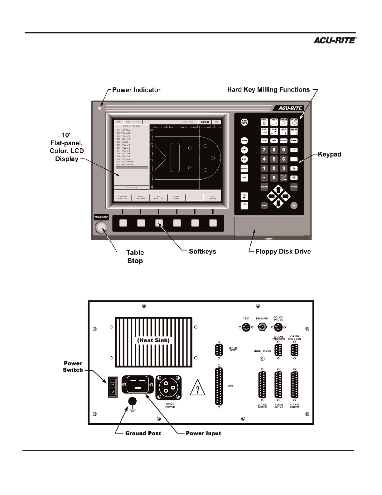
Front View of Operator Console
Rear View of Operator Console
Page 12

INTRODUCTION
MILLPWR
®
Operation Manual
1-3
Main Function Keys
Switch from absolute to incremental
(or vice versa) in the DRO display and
milling function numeric fields.
Manipulate a part graphic.
Display the digital readout.
Exit from a milling function.
Add a step to the program once
you have completed an entry
form.
Display the program screen.
Keypad Layout
Milling Functions
Use these keys to create a program. All but
BLEND may also be used as one-time milling
functions from the DRO display.
Special Function Keys
INFO
MM
SETUP
CALC
Access information about any
MILLPWR function.
Switch from inches to millimeters or vice versa.
Add to the tool library, set
feed rates, change display
options and define other
system parameters.
Perform standard (+, -, x, ÷),
trigonometry, geometry and
RPM calculations.
Cursor and Motion Control
GO
STOP
FEED+
FEED-
ARROWS
Start a program.
Press this key once to pause
the program, twice to exit.
Increase or decrease the feed
rate.
These keys enable you to position the table or move the cursor.
Numeric Keypad and Calculator
Enter program data and
perform math calculations. Press the
CLEAR
key to delete information from a data field.
Press the
ENTER key
to accept the information you have entered.
Page 13
INTRODUCTION
MILLPWR
®
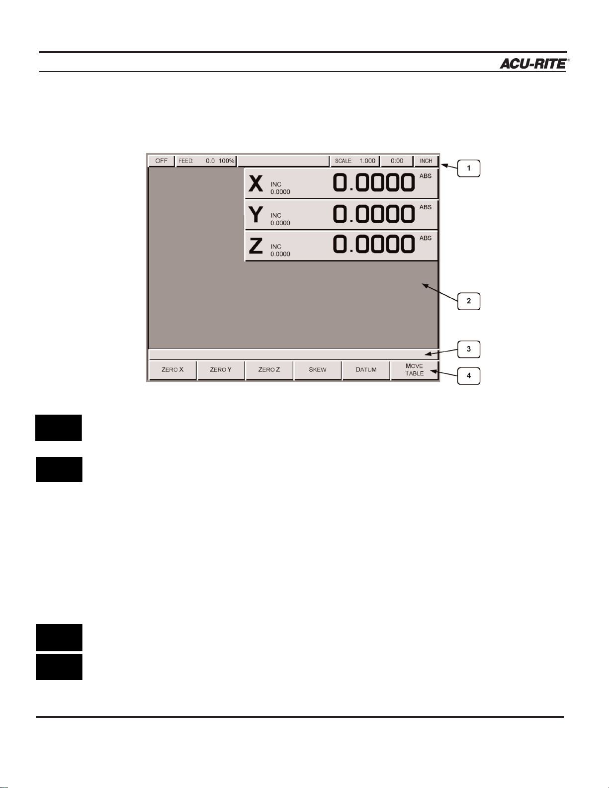
Screen Layout
The MILLPWR display screen is divided into four sections.
Status bar - displays the servo motor status (ON/OFF), feed rate, current tool, scale,
job clock, and the current display setting (inches or millimeters).
Information area - displays information about the job being performed.
• Readout (DRO) - used as a digital readout, the display will show the current
position for each axis.
• Program (PGM) - when programming, a list of program steps (milling functions)
and part-view graphics will be displayed.
• Calculator (CALC) - a TRIG, R.P.M., and geometry calculator are available to
assist with calculating missing information. They can be used as stand-alone calculators or, while programming, the calculations can easily be returned to the program.
Message line - operator prompts and messages will appear here.
Softkeys - variable milling functions appear here; functions are selected by pressing the
softkey directly below each category. When a key appears pressed, it is selected. When
it appears “raised” it is not selected.
Operation Manual
1-4
Page 14

INTRODUCTION
MILLPWR
®
Operation Manual
Table Stop Button
The large red button located in the lower left corner on the front of the
MILLPWR operator
console is the
TABLE STOP. In the event of a malfunction or programming error,
press the
TABLE STOP button to turn off the servo motors. Turning off
the servo motors will immediately stop all table movement.
Conventions
Axis Conventions
Count Direction
When programming a part using
MILLPWR, table movement and tool movement are
determined by the use of positive or negative numbers. MILLPWR has been factory
set with the following positive and negative count directions for the X, Y and Z-axes:
X-axis: The table will move to the left and
the tool will move to the right for a
positive count direction.
Y-axis: The table will move toward you
while the tool moves away from you
for a positive count direction.
Z-axis: The quill will move up (away from
the table surface) for a positive count
direction.
1-5
Pressing the TABLE STOP button will NOT stop the rotation of the cut-
ting tool unless the machine has been configured to do so. In the event
of an emergency, if the machine has not been wired to stop the rotation
of the cutting tool, be prepared to raise the tool in addition to pressing
the
TABLE STOP button.
WARNING
Page 15
INTRODUCTION
MILLPWR
®
Cartesian Coordinates
A cartesian coordinate is a position that can be measured from the X- and Y-axes.
Polar Coordinates
A polar coordinate is a position that is defined by an angle and a radius.
Operation Manual
1-6
Page 16
INTRODUCTION
MILLPWR
®
Operation Manual
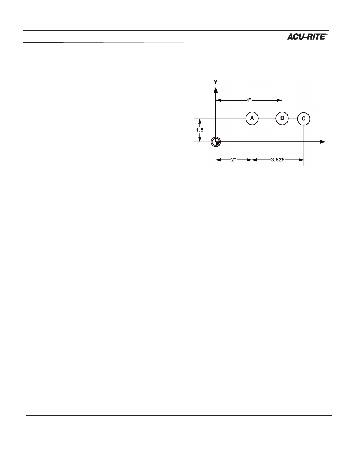
Absolute and Incremental Dimensions
Dimensions that you enter from a print
are either absolute or incremental.
Absolute dimensions are measured
from datum (also known as workpiece
zero). Incremental dimensions are
measured from one point to another.
Holes A and B are dimensioned using
absolute values. Hole C is dimensioned
incrementally from Hole A.
When entering these dimensions, we would say:
Hole A: Position/Drill 002
X 2.0000 ABS
Y 1.5000 ABS
Hole B: Position/Drill 003
X 4.0000 ABS
Y 1.5000 ABS
Hole C: Position/Drill 004
X 3.6250 INC 002 Y 1.5000 ABS
1-7
This indicates that the X position will increment
from the X value in Step 2 (Hole A) above.
Note: Both absolute and incremental dimensions may be used to define a position,
as shown with Hole C.
It’s often easier to describe a location in terms of incremental dimensions rather than
calculate its absolute coordinates.
Page 17

INTRODUCTION
MILLPWR
®
Saving, Backing Up, and Creating Directories for Programs
When you create programs with
MILLPWR, you can save them in any of three
places—within MILLPWR's internal memory, on a 3
1
/2" floppy disk, or on
your PC. Saving your work means it will not be lost if
MILLPWR is powered
down or if there is a power interruption. As you save and back up your pro
grams, you can neatly organize them in any of the following three main
directories ("MILLPWR," "A:" and "
REMTSTOR") or in personalized subdirec-
tories that you can create.
MILLPWR is also equipped with a backup feature that enables you to make
duplicate copies of your saved programs. We recommend that you back up
your programs regularly to avoid accidental loss or other problems that may
prevent you from recovering your original programs. Backing up programs
takes only a few moments—and will save you valuable time if a problem
does occur.
Note:
Before you save or back up programs onto your PC, refer to
Remote Storage and Setup for instructions.
For more details about how to save programs, back up files and create directories, refer to Programming.
Operation Manual
1-8
If you are creating a long program, don’t wait
until the end to
save your work.
Frequent saving
reduces the risk
of losing your
work due to a
power interruption.
Page 18
DRO
MILLPWR
®
Operation Manual
2-1
DRO
Start Up
Power Up
Turn the power switch (located on the rear of the operator console) to “I.” The Power
Indicator (located in the upper left corner of the operator console) will light up.
Anytime the system is inactive for approximately 20 minutes, the LCD display will
shut off, and a blank screen will appear. This screen saver function is designed to
prolong the life of the operator console display. If the screen is blank, check that
the Power Indicator light is illuminated. Press any key on the operator console or
move the table and the display will reappear. If the Power Indicator light is not
illuminated, then power to the
MILLPWR system has been interrupted.
Screen Saver
Page 19
DRO
MILLPWR
®
Operation Manual
2-2
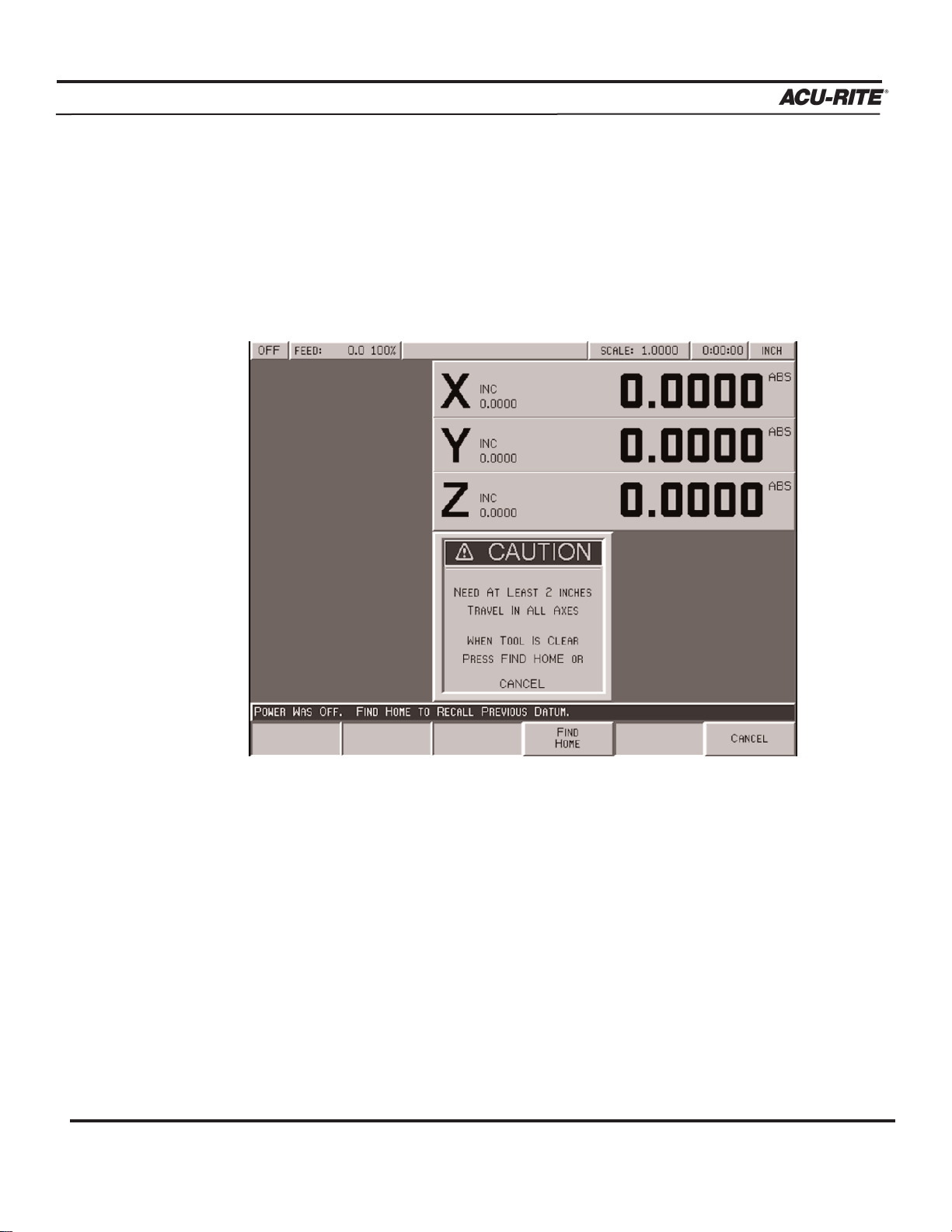
You must find home before you run a program. To find home immediately after startup,
press the FIND HOME softkey. Otherwise, press the DATUM softkey, then the FIND HOME
softkey. The table will automatically move a few inches along the X- and Y-axes to find
home.
If you don't find home before moving the table, you will risk exceeding the table's
travel limits and damaging the milling machine,
MILLPWR or both.
Datum is a
term used to
describe "workpiece zero" or
"absolute zero."
After you power
up and find
home, you
can quickly
move to datum
by pressing the
POS key, followed by the
GO key.
With Position-Trac, there is no need to leave the system powered up
when it is not being used. You will be able to easily, quickly and accurately reestablish workpiece zero immediately after you restart
MILLPWR.
After home has been found, the tool’s position (relative to your most
recent datum) will be displayed.
When finding home, MILLPWR will use ACU-RITE’s advanced
Position-Trac™technology. Position-Trac works by using a very precise
distance-encrypted reference mark line pattern that's been placed onto
each ACU-RITE precision glass scale included with the
MILLPWR
system. Proprietary software decodes the line pattern which then allows
you to accurately find home and reestablish workpiece zero from any
position.
Finding Home
Page 20
DRO
MILLPWR
®
Operation Manual
2-3
DRO Functions
The digital readout (DRO) display shows you the current tool position. While operating
in the DRO mode, you can use several functions, such as skew and datum, to set up
a job. You can also use this as a normal DRO when you use your machine manually.
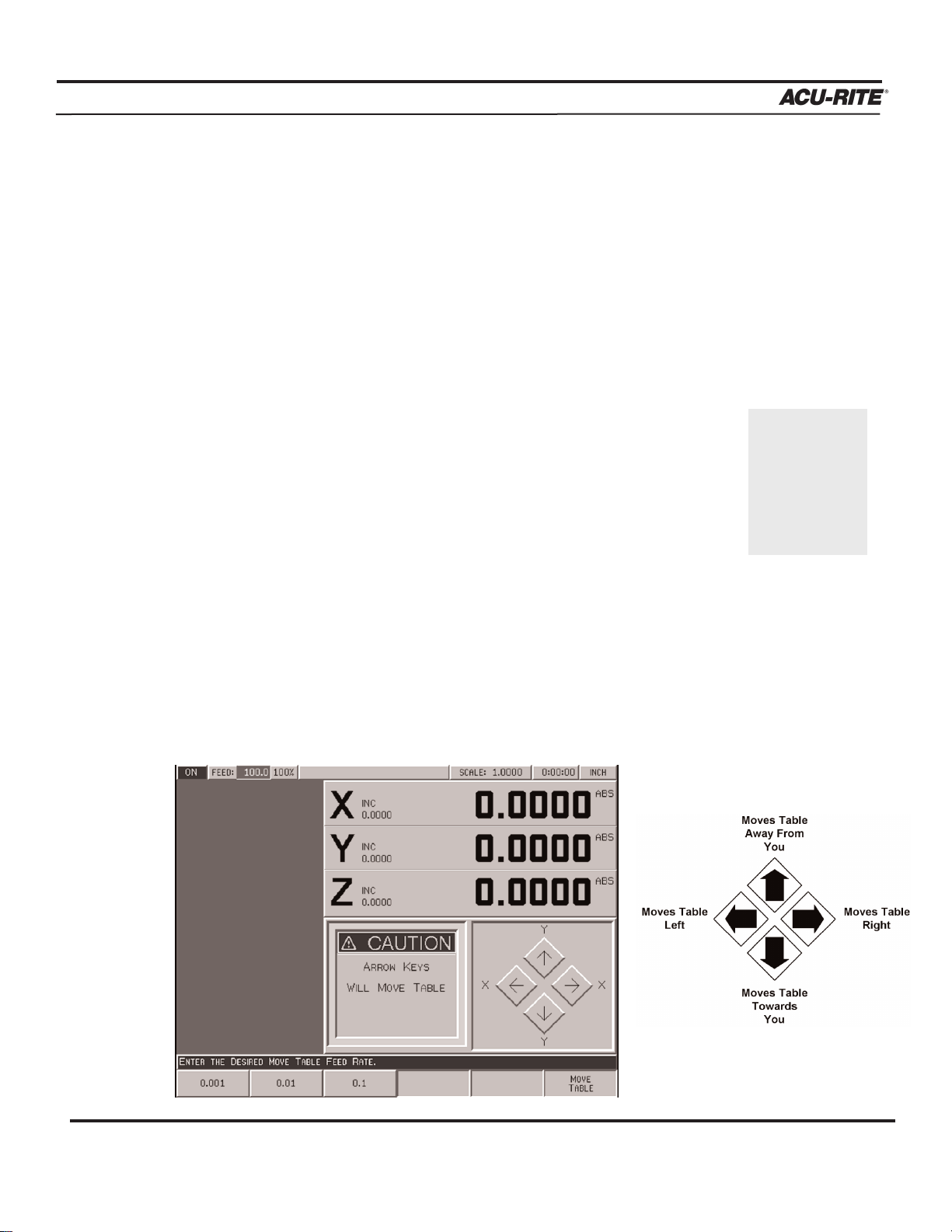
Move Table
The move table feature lets you move the table rapidly (or at an established feed rate)
using the arrow keys.
• Press the
MOVE TABLE softkey to turn the servo motors on. Press
it again to turn them off.
• Enter the desired feed rate or skip this step to move at a rapid
feed rate. Press the
CLEAR key to enter a new feed rate.
• If you want the arrow keys to move the table in increments, press
the
0.001, 0.01 or 0.1 softkey. (A different set of softkeys will appear if you are mea-
suring in millimeters.)
• Move the table. You can move the X- and Y-axes simultaneously by pressing
two arrow keys at the same time.
• Press the
FEED+ and FEED- keys to adjust your feed rate.
It’s a good idea
to fold in the
handles before
moving the
table.
Page 21

DRO
MILLPWR
®
Operation Manual
2-4
Teach Position
Whenever an X, Y or Z coordinate is being entered the
TEACH POSITION softkey will be
available. Pressing this key will place the current absolute position in the coordinate entry
field.
To “teach” MILLPWR a coordinate (while programming a milling function,
such as a line):
• Using the arrow keys, highlight the X-, Y- or Z-axis field.
• Move the tool, indicator, or electronic edge finder to the position you
want to teach.
• Press the
TEACH POSITION softkey to enter that location and press
ENTER. (With an electronic edge finder, the points will automati-
cally be entered on contact—even if you over-travel.) See Using An
Electronic Edge Finder.
· Repeat the steps above for each axis and each location you want to
teach.
· Press USE to accept the information or press CANCEL to return to the
previous screen without saving the information.
As you are
programming
or using a
milling function, you can
switch
between the
DRO and PGM
screens without losing the
program.
Page 22

DRO
MILLPWR
®
Operation Manual
2-5
Using an Electronic Edge Finder
An ACU-RITE
®
Electronic Edge Finder can “teach” positions, find the center point of a circle,
skew a part or locate datum (also known as workpiece zero) by simply “touching off” on the
part. The greatest advantage of an electronic edge finder is that it instantly senses when contact
is made allowing for over-travel.
MILLPWR SETUP PARAMETERS define the “Diameter” and “Unit” of measure (either inches or
millimeters) for an electronic edge finder. Once this information has been entered, MILLPWR
will automatically compensate for the radius of the tip of the electronic edge finder when performing any of the operations mentioned above.
T
o define the diameter and unit of measure:
• Press the SETUP key and highlight “Electronic Edge Finder.”
• Press the
ENTER key.
• Enter a value for the edge finder’s diameter and unit of measure (inches or mil-
limeters), then press the
USE key.
• Press the
USE NEW SETTINGS softkey.
To teach
MILLPWR a coordinate, highlight the appropriate field then slowly move the table until
the electronic edge finder touches the workpiece. When the electronic edge finder touches the
part’s surface, the coordinate will appear in the data field. The electronic edge finder is active
whenever an entry field is highlighted.
Page 23
DRO
MILLPWR
®
Operation Manual
2-6
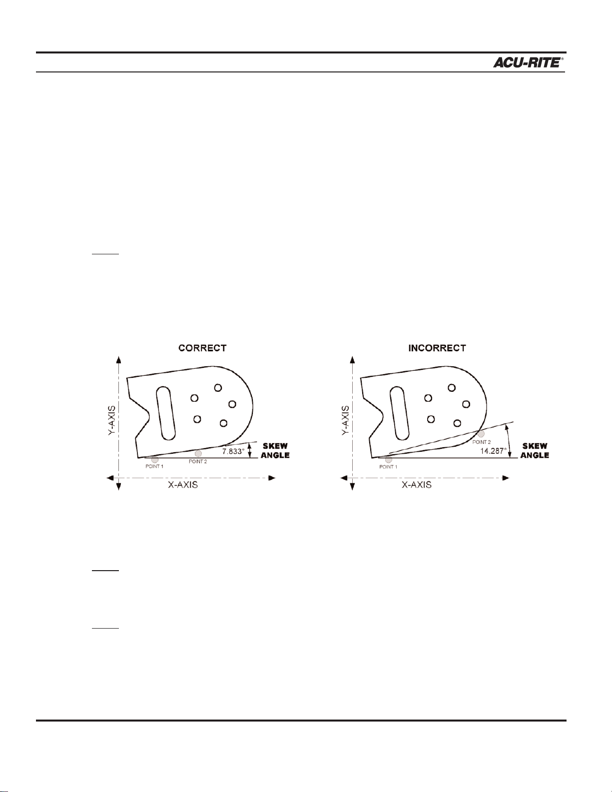
Skewing a Part
Save time setting up a job by skewing the part. The skew function automatically compensates for the angle offset of thepart. If a part is not perfectly parallel with either the X- or Yaxis, indicating it in is not necessary.
To skew a part, simply “touch off” on two or more points along one axis (either X or Y).
Use an electronic edge finder to skew a part, or use a mechanical indicator and teach position—either way, it’s fast and easy.
Note: Choose a line to make parallel with the table’s X- or Y-axis—do not enter coordinates along a curve, along two different lines, or along a line that’s positioned at
a true 45 degree angle. MILLPWR will calculate the skew angle based upon a
straight line between the points entered.
If you are working with a part that has a rough edge, it’s best to enter multiple points along
the straightest edge so that
MILLPWR can more accurately compensate for the skew angle.
Note:
When two or more points are entered in the skew calculator MILLPWR will calculate
the angle and adjust the X and Y plane. Angles that are less than 45° are adjusted
down to the X-axis, and angles greater than 45° adjust up to the Y-axis.
Note:
The skew feature does not not work with G-code programs. Remove any skew
angle prior to running a G-code program.
Page 24

DRO
MILLPWR
®
Operation Manual
2-7
To skew a part or vise:
Using an electronic edge finder
• Press the
SKEW softkey.
• Touch off on two or more points along any single straight edge
of the part. Notice the “Points” and “Angle” change as
points are entered.
• Press the
USE key to accept all of the points and return to the
DRO screen. Press the CANCEL key to return to the DRO screen
without accepting any points or affecting the previous skew
angle.
The
CLEAR ANGLE softkey will reset the number of points and
the skew angle to zero.
Using teach position:
• Press the
SKEW softkey.
• Move the table so that a mechanical indicator rests against any straight edge
on the part. Press the TEACH POSITION softkey to enter the coordinate.
Notice that the “Points” change.
• Now move the table so that the mechanical indicator touches another point on
the same straight edge. Press the
TEACH POSITION softkey. Notice that
the “Points” and “Angle” change.
Repeat this process for any additional points.
• Press the
USE key to accept all of the points and return to the DRO screen.
Press the
CANCEL key to return to the previous screen without affecting the
previous skew angle.
The
CLEAR ANGLE softkey will reset the number of points and the angle to zero.
Here a workpiece was
used as an
example. You
can also
“touch off” on
a vise or fixture.
Page 25
DRO
MILLPWR
®
Operation Manual
2-8
Establishing Datum
Datum, also known as workpiece zero or absolute zero, is the point of reference that
MILLPWR bases all of the part's coordinates from.
It is necessary to establish datum for every job. Datum's location may be indicated on a
print; if it's not, establish a datum that enables most of the part's dimensions to be entered
directly, with the least amount of calculations.
When establishing datum, you may find it easiest to locate a known point on each axis, such
as the edge of the part or a location on the vise or fixture.
Refer to the procedure below as a basic guide for establishing datum. Decide to "touch off"
using an electronic edge finder, a mechanical edge finder or a tool. Datum may be set at a
point on the top surface or a position above or beneath the surface. X and Y datum may be
set on an edge, or offset into or off of an edge, or where there's no material present (such as
in the center of a circular part). There are many possibilities-- do what’s easiest for a particular job.
MILLPWR will retain datum even after the system has been powered down.
(See Finding Home).
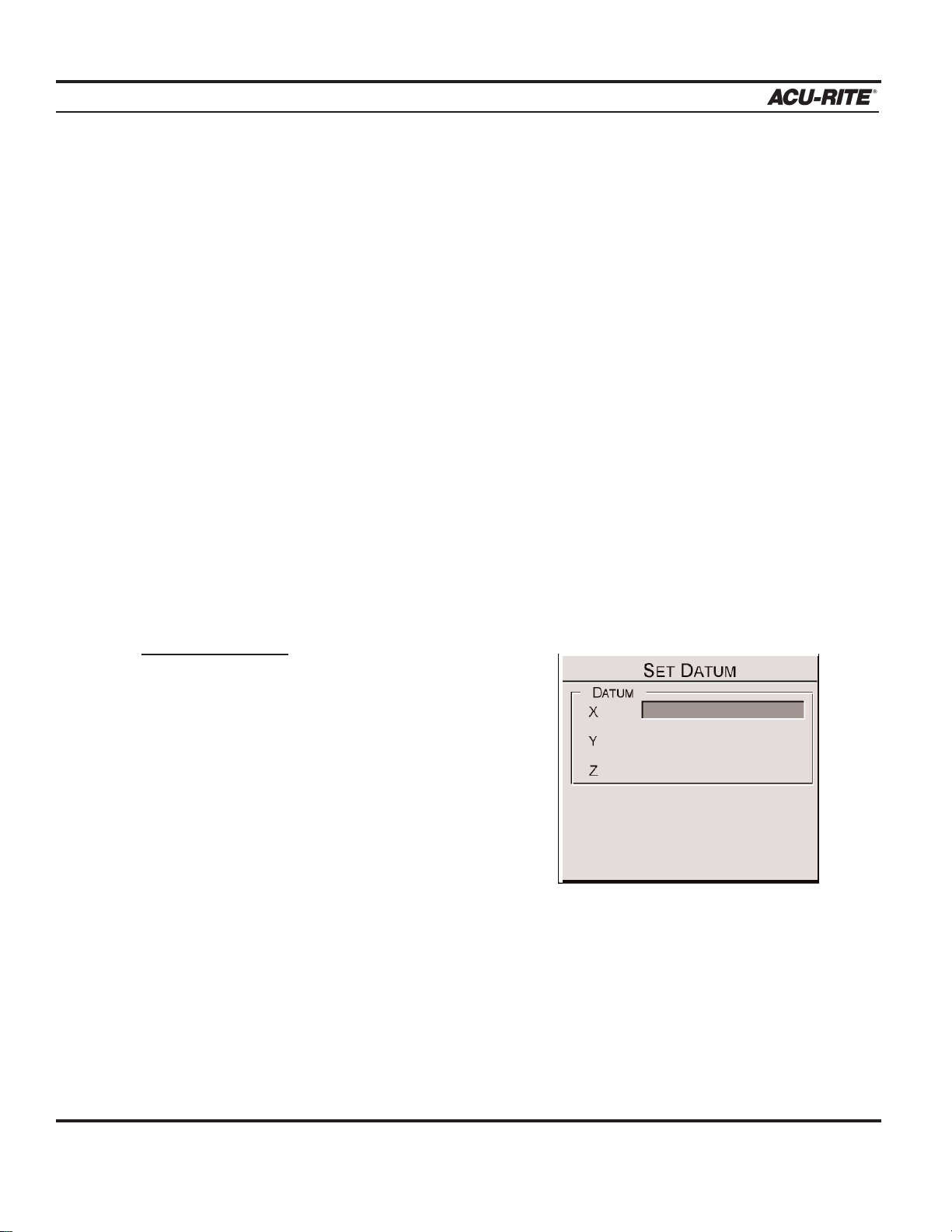
Define datum one axis at a time. Begin here with the X-axis:
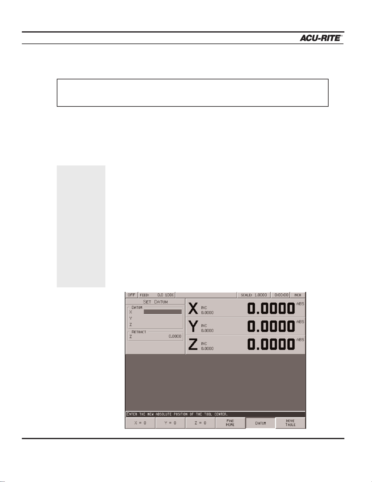
• From the DRO screen, press the
DATUM softkey.
• Insert the proper tool into the spindle.
T
o establish datum:
Where and how datum is establish will vary from
job to job. One of the most common methods of
establishing datum is described below. Apply the
same principles when setting datum for future jobs,
making adjustments to the procedure as needed.
The following example will establish datum at the
corner where the left, front and top surfaces of the
part intersect. This is accomplished by "touching"
each face with the tool used to cut the part.
Page 26

DRO
MILLPWR
®
Operation Manual
2-9
• Position the tool so that it is near, but not touching,
the left side of the part.
• Lower the tip of the tool so that it falls below
the top surface of the part.
• Move the table along the X-axis slowly, while
spinning the tool by hand. Pay close attention as
the tool approaches the part— a subtle bump will be
felt when they come into contact.
Stop the table at the moment the tool touches the part.
• Using the keypad, enter the radius of the tool (the distance from the
center of the tool to the edge of the part). Be sure to specify if it’s
a negative value.
Note:
For this example, specify a negative value, because the tool's
center is on the negative side of datum
(refer to Axis Conventions).
• Press the
ENTER key.
Now set datum for the Y-axis using the same procedure:
• Position the tool so that it is near, but not touching,
the front face of the part. The tip of the tool should
fall below the top surface of the part.
• Move the table along the Y-axis, slowly spinning the
tool by hand. Pay close attention as the tool
approaches the part— A subtle bump will be felt when they make contact with
each other. Stop the table at the moment the tool touches the part.
• Using the keypad, enter the radius of the tool into the"Y" field
(be sure to specify if it is a negative value).
• Press the
ENTER key.
Use the MOVE
TABLE softkey
to help with
long table
moves.
Page 27

DRO
MILLPWR
®
Operation Manual
2-10
Set datum for the Z-axis:
• Position the tool so that its tip touches the top surface
of the part.
• Using the keypad, enter "0" into the "Z" field
(or press the Z = 0 softkey).
• Press the
ENTER key.
• Press the
USE key.
Datum has now been established for X, Y, and Z
It's a good idea to test the datum setting before programming. To confirm
that the new datum is correct:
• Raise the tool and move the table until
both the X- and Y-axes displays read
"0.0000."
• Lower the tool until it touches
the part.
• Check the tool's position—the lower left
corner of the part should be directly
beneath the center point of your tool.
• Now check the readout. If the Z-axis display says "0.0000," then the datum is
accurate. If a value other than 0.0000 appears in the Z-axis display, repeat the
procedure for establishing datum.
You can quickly
move to Datum
for X and Y by
pressing the
POS key. Check
that your
position is
0.0000 ABS
for both X and
Y, then press
the GO key.
Page 28

DRO
MILLPWR
®
Operation Manual
2-11
Hard Key Milling Functions
Most of the hard key milling functions can be used
individually as one time milling routines without creating a program.
The one hard key milling function not used as
a one-time milling function is BLEND. The blend function inserts a connecting radius between two features
(steps) in a program.
Hard key milling functions are ideal for jobs that only require one operation. Provide the
required information once, and MILLPWR will “remember” it for each piece machined.
Example:
To drill the same bolthole pattern on several identical parts. Instead of creating a one-step
program, save time by using the
HOLES hard key milling function from the DRO screen.
• First, set up a tool and workpiece.
• From the DRO display, press the
HOLES key, and select which hole pattern you
want to drill from the available softkeys—ROW, FRAME, ARRAY, or BOLT CIRCLE.
• Enter the required information and press the
GO key to machine the first part.
• Change the part. Press the
HOLES key, then the pattern.
MILLPWR will automatically refer to the prior data entered for each part thereafter.
Page 29

DRO
MILLPWR
®
Operation Manual
2-12
To change the hole pattern size, location or number of holes, press the HOLES key
again. Now press the appropriate softkey, enter the new information and then press the
GO key.
This may also be applied to rectangles, circles, lines and arcs. The rectangle and circle
milling functions require you to establish a tool offset. Lines and arcs only require a
tool offset if the tool follows a left or right offset. It’s a good idea to set up a tool
before using either of these function keys. Refer to Program Steps for a complete
description of each function.
Note:
The “Tool” setting on MILLPWR’s status bar (located at the top of the display)
will indicate which tool has been selected. If the “Tool” status bar is blank,
no tool has been selected.
Page 30

PROGRAMMING
MILLPWR
®
Operation Manual
PROGRAMMING
Programming Considerations
"From" and "To" Points
Lines and arcs are defined by their “From” point
(the point where they begin) and “To” point (the
point where they end).
Depth of Cut
Since the Z-axis is not controlled by a servo motor, make changes to the depth
of cut manually.
If the Z-axis depth is programmed,
MILLPWR will preset the programmed value into the
DRO. When it's time,
MILLPWR will display the DRO screen and ask you to position the
depth.
If you are not programming a depth, leave it set to 0.
Tool Offset
By using left and right offsets, dimensions can be programmed as identified on the print.
When a line, arc, frame, etc., is programmed, use the “Tool Offset” field to tell
MILLPWR
which side of the part the tool should be cutting on.
To determine which offset to use, picture yourself standing behind the tool as it is moving.
If the tool is on the left side of the workpiece, use a "left" offset. If the tool is on the right
side of the workpiece, use a "right" offset.
3-1
Page 31

PROGRAMMING
MILLPWR
®
With a "center" offset, the programmed
dimensions are for the center of the tool.
For some milling functions, like frame
and arc, "inside" and "outside" offsets are
available to make it easier to define a tool
offset.
Datum Selection
Datum is where workpiece (absolute) zero
is located. If datum isn't defined on the print, then determine datum based upon where most
of the dimensions originate. Pick a point which will allow most of the dimensions to be
entered directly, with few (if any) calculations (refer to Establishing a Datum).
Absolute vs. Incremental Dimensions
MILLPWR allows both absolute and incremental dimensions. A dimension measured from
the point defined as datum is an absolute dimension. A dimension measured from any other
point is an incremental dimension.
In the example below, the print on the left shows datum located at the center of Hole
F—all dimensions are absolute.
The print on the right shows datum located in the lower left corner—point A. Most of these
dimensions are incremental.
Operation Manual
3-2
Page 32

PROGRAMMING
MILLPWR
®
Operation Manual
3-3
Continuous Milling
MILLPWR will cut a continuous contour of lines and/or
arcs, without stopping.
MILLPWR will automatically rec -
ognize continuous contours as they are programmed.
There are no special key presses or other functions to
learn.
For lines and arcs to be continuous, they must:
• have the same depth
• be cut with the same tool
• be cut using the same tool offset
• share a common “From” or “To” point (one step must
end at the point where next begins)
If one step follows another,
MILLPWR assumes that they are to be connected. It auto-
matically fills in the “From” point, “Depth,” and “Tool Offset.” To complete the step, fill in
the “To” point and press
USE.
Note:
MILLPWR will allow different feed rates within each step of a contour.
Single lines
indicate an
open-ended
continuous
tool path.
Double lines
indicate a
closed continuous tool
path.
Note: An “X” after a step number indicates that the step is invalid. Highlight the step, press enter
and correct the information as needed. Press use when finished.
Page 33

PROGRAMMING
MILLPWR
®
Operation Manual
3-4
Creating a Program
• Press the PGM key, and the following program screen will appear.
Programs are created by developing a list of milling steps to be performed. As steps are
added, each step will immediately be drawn on the screen displaying a graphic represen-
tation of the part in progress.
• To enter a milling step, press the appropriate hard key or softkey milling function (such
as Tool). The milling function keys are the eight yellow keys located in the upper righthand corner of your keypad. When pressed, the function selected will appear in the program listing and the form opens allowing the information describing the step to be
entered.
Program
steps are
added
here.
Enter information
about a milling
function—such
as an arc—into
windows like
this.
Page 34

PROGRAMMING
MILLPWR
®
Operation Manual
3-5
• After entering all the data for a step, press the USE key to add the step to the program.
This immediately updates the part graphic and positions the cursor for the next step.
To exit a milling function without completing it, simply press the
CANCEL key.
• To edit a step, use the arrow keys to highlight the step and press
ENTER. After making
changes, press
USE to accept the changes.
• To delete a step, highlight the step to be deleted, then press
CLEAR.
• To insert a step between the two existing steps, position the cursor on the lower step, and
press the desired milling function key.
In addition to the milling functions, the MORE STEPS softkey displays a number of other useful
steps, such as
CUSTOM POCKET, ISLAND, MIRROR, REPEAT and ROTATE—each of which are
described in the Program Steps section of this manual.
Page 35

PROGRAMMING
MILLPWR
®
Operation Manual
3-6
The View Key
To see part graphics in more detail, press the
VIEW key to access the following softkeys:
FOLLOW TOOL
The FOLLOW TOOL softkey will automatically adjust the part graphic so that the tool is
always in view during Dry Run and the execution of the program.
SHOW TOOL PATH
The SHOW TOOL PATH softkey shows the tool's cutting path during the Dry Run and execu-
tion of a program. With this feature enabled, the toolpath remains highlighted.
ZOOM IN, ZOOM OUT and RESTORE
The ZOOM IN softkey will magnify the part graphic. The arrow keys will adjust the view,
up, down, left and right. The
ZOOM OUT softkey will de-magnify the part graphic.
RESTORE will return the part graphic to its original size.
T
ip:
Use FOLLOW TOOL, SHOW TOOL PATH and ZOOM functions simultaneously.
Press the
VIEW key (or the CANCEL key) to return to the PGM screen.
Page 36

PROGRAMMING
MILLPWR
®
Operation Manual
3-7
Running a Program
There are a few things that may need to be done before running a program, such as skewing
the part and establishing datum.
Skewing a Part
Note:
It is important to skew a part prior to establishing datum for accuracy.
Save time setting up a job by skewing the part. The skew function automatically compensates for the angle offset of the part. If a part is not perfectly parallel with either the X- or
Y-axis, indicating it in is not necessary.
To skew a part, simply “touch off” on two or more points along one axis (either X or Y).
Use an electronic edge finder to skew the part, or use a mechanical indicator and teach
position—either way, it’s fast and easy.
Note:
Choose a line to make parallel with the table’s X- or Y-axis—do not enter coordinates along a curve, along two different lines, or along a line that is positioned
at a 45 degree angle.
MILLPWR will calculate the skew angle based upon a
straight line between the points entered.
If you are working with a part that has a rough edge, it’s best to enter multiple points
along the straightest edge so that
MILLPWR can more accurately compensate for the skew
angle.
Note:
When two or more points are entered in the skew calculator MILLPWR will calcu-
late the angle and adjust the X and Y plane. Angles that are less than 45° are
adjusted down to the X-axis, and angles greater than 45° adjust up to the Y-axis.
Note:
The skew feature does not not work with G-code programs. Remove any skew
angle prior to running a G-code program.
Page 37

PROGRAMMING
MILLPWR
®
Operation Manual
3-8
Using an electronic edge finder:
• From the DRO screen, press the
SKEW softkey.
• Touch off on two or more points along any single straight edge
of the part. Notice that
the “Points” and “Angle” change as you enter points are entered.
• Press
USE to accept all of the points and return to the DRO screen. Press CANCEL to
return to the DRO screen without accepting any points or affecting the previous skew
angle.
The
CLEAR ANGLE softkey will reset the number of points and the skew angle to zero.
Using teach position:
• From the DRO screen, press the SKEW softkey.
• Move the table so that a mechanical indicator rests against any straight edge
on the
part. Press the
TEACH POSITION softkey to enter the coordinate. Notice that the
“Points” change.
• Now move the table so that the mechanical indicator touches another point on the same
straight edge. Press the
TEACH POSITION softkey. Notice that the “Points” and “Angle”
change.
Repeat this process for any additional points.
• Press
USE to accept all of the points and return to the DRO screen. Press CANCEL to
return to the previous screen without affecting the previous skew angle.
The
CLEAR ANGLE softkey will reset the number of points and the angle to zero.
Page 38

PROGRAMMING
MILLPWR
®
Operation Manual
3-9
Establishing Datum
Datum, also known as workpiece zero or absolute zero, is a point of reference that
MILLPWR bases all of the part's coordinates from.
It is necessary to establish datum will need to be establish for every job. Datum's location
may be indicated on a print; if it's not, establish a datum enables most of the part's dimensions to be entered directly, with the least amount of calculations.
When establishing datum, locate a known point on each axis, such as the edge of the part or
a location on a vise or fixture.
Refer to the example below as a basic guide for establishing datum. Decide to
"touch off" using an electronic edge finder, a mechanical edge finder, or a tool. Datum may
be set at a point on the top surface or a position above or beneath the surface. X and Y datum may be set on an edge, or offset into or off of an edge, or where there's no material
present (such as in the center of a circular part). There are many possibilities, do what is
easiest for the particular job.
MILLPWR will retain the datum you've set after your system has been powered down.
(See Finding Home).
T
o establish datum:
Where and how datum is established will vary from job to job. One of the most common
methods of establishing datum is described below. Apply the same principles when setting
datum for future jobs, making adjustments to the procedure as needed.
The example below will establish datum at the corner where the left, front and top surfaces
of the part intersect. This is accomplished by “touching” each face with the tool used to
cut the part.
Define datum one axis at a time. Begin with the X-axis:
• From the DRO screen, press the
DATUM softkey.
• Insert the proper tool into the spindle.
Page 39

PROGRAMMING
MILLPWR
®
Operation Manual
3-10
• Position the tool so that it is near, but not touching,
the left side of the part.
• Lower the tip of the tool so that it falls below the top
surface of the part.
• Move the table along the X-axis, while slowly spinning the
tool by hand. Pay close attention as the tool approaches the
part—a subtle bump will be felt when they come into contact. Stop the table at the moment the tool touches the part.
• Using the keypad, enter the radius of the tool (the distance from
the center of the tool to the edge of the part) into the “X:” field.
Be sure to specify if it’s a negative value.
Note:
For this example, specify a negative value,
because the tool's center is on the negative side of datum
(refer to Axis Conventions).
• Press the
ENTER key.
Now set datum for the Y-axis using the same procedure:
• Position the tool so that it is near, but not touching, the
front face of the part. The tip of the tool should fall
below the top surface of the part.
• Move the table along the Y-axis, slowly spinning the
tool by hand. Pay close attention as the tool approaches the part—a subtle bump will
be felt when they come into contact. Stop the table at the moment the tool touch-
es the part.
• Using the keypad, enter the tool's radius into the"Y:" field
(be sure to specify if it is a negative value).
• Press the
ENTER key.
Use the MOVE
TABLE softkey
to help with
long table
moves.
Page 40

PROGRAMMING
MILLPWR
®
Operation Manual
3-11
Set datum for the Z-axis:
• Position the tool so that its tip touches the top surface of
the part.
• Using the keypad, enter "0" into the "Z:" field (or
press the Z = 0 softkey).
• Press the
ENTER key.
• Press the
USE key.
Datum has now been established for X, Y and Z.
It's a good idea to test the datum setting before programming.
To confirm that the new datum is correct:
• Raise the tool and move the table until both the
X- and Y-axes displays read "0.0000."
• Lower the tool until it touches the part.
• Check the tool's position—the lower left corner
of the part should be positioned directly beneath the
center point of the tool.
• Now check the readout screen. If the Z-axis
display says "0.0000," then the datum is accurate. If a value other than 0.0000 appears
in the Z-axis display, repeat the procedure for establishing the datum.
You can quickly
move to datum
for X and Y by
pressing the
POS key. Check
that the go to
position is
0.0000 for both
X and Y, then
press the GO
key.
Page 41

PROGRAMMING
MILLPWR
®
Operation Manual
3-12
Testing Your MILLPWR Program
Before machining a part, it is always a good idea to test the program for things like the correct tool path, count direction, feed rate, and sequence of operations.
MILLPWR provides sev-
eral run-time options to provide assistance. From the PGM screen, press
RUN OPTIONS to
display the following softkeys:
Press any softkey to activate the option; press it again to deactivate it.
SINGLE STEP
Normally, a continuous contour will be machined without stopping. With “Single Step” activated,
MILLPWR will stop after each step. Use this feature to check the position of the tool
relative to the part and ensure that the tool path and other program
details are correct.
DRY RUN
With “Dry Run” activated, MILLPWR will run the program at high speed
without stopping. Follow the sequence of steps and visually follow the
position of the tool relative to the part to ensure that the tool path and
other program details are correct.
The dry run speed is defined in “Setup.” A prompt asking to raise the tool is displayed
before the dry run begins.
GRAPHICS ONLY
With this activated, the table does not move, but the graphics will show how the part will be
cut. Use this feature to see all the normal feed rates, tool changes and so on.
T
ip:
Dry Run and Graphics Only can be used to quickly verify your program.
To test the program quickly,
press the DRY
RUN and
GRAPHICS
ONLY softkeys.
Page 42

PROGRAMMING
MILLPWR
®
Operation Manual
3-13
MANUAL POSITIONING
Use this option to position the table using the handles. MILLPWR will operate just like a programmable readout—each target position will be preset into the readout, and you will be
prompted to position the table manually. This feature is especially useful when navigating
around islands.
DISABLE LOOK AHEAD
Normally, MILLPWR checks each step in a continuous tool path with other steps to determine
if there is an intersection in the tool's cutting path (such as a figure 8). This is called look
ahead. Press the
DISABLE LOOK AHEAD softkey, the program will run without performing
this function.
Page 43

PROGRAMMING
MILLPWR
®
Operation Manual
3-14
Pressing the GO Key
To run a program, with or without any of the run options, highlight the step to begin with and
press
GO. MILLPWR will automatically pause at points that require action (e.g., change tools,
raise the quill, etc.) After the task has been completed, press the
GO key again, and the table
will move to the next position. At this point, you will be prompted to drill or set the tool to the
programmed depth.
Before any rapid move,
MILLPWR will display a warning message indicating that the table is
about to move at high speed. At this time, check that the tool is clear of the workpiece and fixturing. Pressing the
GO key, confirms that the tool is clear and ready for the table to move.
Pressing the
STOP key once, causes the tool to pause in its cutting path, and
the following prompt will appear:
Press
GO to resume machining, or STOP again to end the program execu-
tion. To restart a program, move to the step you wish to begin with and then
press
GO.
Note:
If starting in the middle of a program and the tool programmed is not
displayed in the current tool field, start the program at the programmed tool step for that tool.
Whenever you are about to run a program, check that the
handles are recessed.
The remote
STOP/GO
switch acts as
PAUSE if the
table is moving
and as GO if
the machine is
paused or
stopped.
To move quickly to a step, key
in its number
(look in the
message bar),
and press
ENTER.
Page 44

PROGRAMMING
MILLPWR
®
Operation Manual
3-15
Feed+ and Feed-
The FEED+ and FEED- keys will change the feed rate by a certain percentage with
each key press. The feed rate percentage will be displayed in the status bar at the top
of the screen. A feed rate percentage of 100% means that actual feed rates will run at
100% of the programmed feed rates. If the feed rate percentage is 50%, actual feed rates
will run at half of the programmed feed rates.
Press the
FEED+ and FEED- keys at any time, even while the table is moving.
Page 45

PROGRAMMING
MILLPWR
®
Operation Manual
3-16
Machining to Zero
MILLPWR is factory preset in a distance to go display view. Any dimension programmed
will be "preset" into the readout display. Every move will begin at the preset value and end
at zero.
If a depth has been programmed, a prompt will instruct you to position the Z-axis.
MILLP-
WR
will preset the value into the readout's Z-axis. The DRO screen will appear, along with
the following prompt:
• Position the Z-axis until the absolute display is 0.0000.
To set up
MILLPWR to the incremental travel display view refer to System Setup. In this
view, every move will begin at zero and end at the programmed position. For example, a
programmed depth of -0.5000, will display, the following prompt:
• Move the Z-axis until the absolute display shows the target position (e.g., -0.5000”).
Page 46

PROGRAMMING
MILLPWR
®
Operation Manual
3-17
Program Functions
Accessing Load, Save, Delete, Merge, Backup and Directory Options
MILLPWR offers several versatile features for loading, saving, deleting, merging and
backing up programs. Use these features to create directories to easily organize your programs.
To access these features, from the PGM screen, press the
PROGRAM FUNCTIONS
softkey.
Use these keys to load a program, save the program, delete programs, merge a saved program into an open one, create a backup copy, or access, create or delete a directory.
Page 47

PROGRAMMING
MILLPWR
®
Operation Manual
3-18
Directories
One of the best ways to keep programs organized is to save them in directories.
Directories are like file folders—they should be clearly labeled and contain closely related projects. They may be used to group programs by job, operator, date, customer, or
any other method.
• Press the
PROGRAM FUNCTIONS softkey, then press the DIRECTORY softkey.
These keys can create a directory, open an existing directory, or delete a directory that
you no longer need.
Note:
A directory can only be deleted if it is empty. First delete or move all part programs from a directory prior to deleting it. See Deleting A Directory.
Page 48

PROGRAMMING
MILLPWR
®
Operation Manual
3-19
Creating a Subdirectory
The best approach to take when creating a subdirectory is to decide
first where to place it. A directory can be placed on
the"MILLPWR"directory, on a floppy disk ("A:") directory, or on a PC
("REMTSTOR") directory, or placed within other subdirectories.
In the example below, four subdirectories have been created to keep
programs better organized. In this case, specific directories were created
for three customers. "COMPANY1" has placed several part orders for a
single month. To help find those part programs quickly and easily, they
were saved in the subdirectory labeled "APRIL99."
The subdirectories COMPANY1, COMPANY2 and COMPANY3, were created with
MILLPWR as the main directory.
When the APRIL99 subdirectory was created, COMPANY1 was selected as the directory.
Another subdirectory can be created under APRIL99, another one under that, one under
that, and so on.
We recommend
creating matching directories
on MILLPWR
and your PC.
This will make it
easier to keep
your original
programs and
backup programs organized.
Page 49

PROGRAMMING
MILLPWR
®
Operation Manual
3-20
To create directories for your programs:
• Press the PGM key, the PROGRAM FUNCTIONS softkey and then the DIRECTORY
softkey. Now press the SELECT DIRECTORY softkey, and a directory list will
appear.
• Highlight the directory where you want to store the new subdirectory.
Select
MILLPWR's internal memory:
"MILLPWR" and any subdirectories should appear under the "Directory"
heading.
Select a 3
1
/2" floppy disk:
Press the
USE FLOPPY softkey. "A:" and any subdirectories should
appear under the "Directory" heading.
Select your PC:
Press the
REMOTE STORAGE softkey. "REMTSTOR" and any subdirec-
tories should appear under the "Directory" heading.
• Using the arrow keys, highlight the existing directory you want to put the new
subdirectory in. (In this example, we highlighted "MILLPWR," then created a subdirectory entitled "COMPANY1.")
• Press the
SELECT DIRECTORY softkey again to verify your choice. The
"Directory" screen will disappear.
• Now press the
DIRECTORY softkey.
• Press the
CREATE DIRECTORY softkey. You will be asked to name your directory.
• Name your directory using the numeric keys on the operator console or by
selecting letters from the
ALPHABET option. Use the arrow keys to move from
letter to letter then press the
ENTER key to make a selection. Program names are
limited to eight characters, consisting of numbers and/or letters.
The REMOTE
STORAGE softkey will only
appear if
MILLPWR has
been set up for
remote storage.
Page 50

PROGRAMMING
MILLPWR
®
Operation Manual
3-21
• After you have named your directory, press the CREATE DIRECTORY softkey again to
enter your choice. The "Directory" screen will now disappear.
Additional directories (and subdirectories) may be added at any time.
Selecting a Directory
The
SELECT DIRECTORY softkey allows you to open any of the directories that you have
previously created on
MILLPWR's internal memory, on a 3
1
/2" floppy disk, or on your PC.
You may use this feature any time you save or load a program.
• Press the
PROGRAM FUNCTIONS softkey, then the DIRECTORY softkey. Press the
SELECT DIRECTORY softkey—a directory list will appear.
Creating a directory does not mean that the directory is selected. If you plan
to save the current program in the directory you just created, you must select
the new directory first. Otherwise, the program will be saved in the last
directory that was selected.
IMPORTANT
Page 51

PROGRAMMING
MILLPWR
®
Operation Manual
3-22
• Indicate where the directory you want to select is located.
On
MILLPWR's internal memory:
“MILLPWR" and any subdirectories that you have created should appear under
the "DIRECTORY" heading.
On a 3
1
/2" floppy disk:
Insert the 3
1
/2" floppy disk containing the directory into the floppy disk drive
(located in the lower right-hand corner on the front of the operator console) and
press the
USE FLOPPY softkey. "A:" and any subdirectories you have created
should appear under the "DIRECTORY" heading.
On your PC:
Press the
REMOTE STORAGE softkey. "REMTSTOR" and any subdirectories
you have created will appear under the "DIRECTORY" heading.
• Using the arrow keys, highlight the directory you want to open. (If the list is long,
use the
PAGE UP and PAGE DOWN softkeys to scroll through the list more quickly.)
• Press the
SELECT DIRECTORY softkey again. The "DIRECTORY" list will disappear,
indicating that your directory has been selected.
You can now save your program in the directory you have chosen (refer to Saving a
Program); or if you prefer, load an established program from the directory you selected
(refer to Loading a Program).
Page 52

PROGRAMMING
MILLPWR
®
Operation Manual
3-23
Deleting a Directory
MILLPWR will not delete directories that contain programs. First delete each program
and subdirectories stored within the directory (refer to Deleting a Program).
T
o delete a directory:
• From the PGM screen, press the PROGRAM FUNCTIONS and DIRECTORY
softkeys, then press the DELETE DIRECTORY softkey.
• Identify where the directory you want to delete is located.
On
MILLPWR's internal memory:
"MILLPWR" and any subdirectories you have created should appear under
the "DIRECTORY" heading.
On a 3
1
/2
" floppy disk:
Insert the 3
1
/2" floppy disk containing the directory into the disk drive
(located in the lower right-hand corner on the front of the operator console)
and press the
USE FLOPPY softkey. "A:" and any subdirectories you have
created will appear under the "DIRECTORY" heading.
On your PC:
Press the
REMOTE STORAGE softkey. "REMTSTOR" and any subdirectories
you have created will appear under the "DIRECTORY" heading.
• Using the arrow keys, highlight the directory you want to delete.
• Press the
ENTER key. Press the YES softkey to erase the directory or the NO softkey
to cancel.
Page 53

PROGRAMMING
MILLPWR
®
Operation Manual
3-24
Saving a Program
You can save programs in any of three places—on
MILLPWR's internal memory, on a
3
1
/
2" floppy disk, or on a PC. It is always a good idea to save your programs often to
avoid losing valuable information.
• From the PGM screen, press the
PROGRAM FUNCTIONS softkey, then select the
directory where you want to save your program (refer to Selecting a Directory
and/or Creating a Directory).
• Return to the PGM screen, then press the
PROGRAM FUNCTIONS and SAVE softkeys.
You will be asked to name your program (refer to Naming a Program).
• Press the
SAVE softkey. The program's name should now appear in the left column
above the program steps.
If you make any changes, make sure that you save your program again.
Page 54

PROGRAMMING
MILLPWR
®
Operation Manual
3-25
Naming a Program
Before saving a program,
MILLPWR requires you to name it.
• If you want to use letters, press the
ALPHA-
BET
softkey. An alphabet menu will appear
just below the "Program Name" field.
• Using the arrow keys, you can move from one
letter to the next. Press the
ENTER key to
select a letter.
To add numbers to your program name, simply press any of
the number keys on the keypad.
You may choose up to eight characters for your program
name, mixing numbers and letters if you wish.
• Press the
SAVE softkey. MILLPWR will store your pro-
gram in the directory you have selected.
A message will alert you if the program was not saved
properly, or if the name that you have chosen already exists.
If you have
accidentally
selected the
wrong letter or
number, press
the CLEAR key
and rename
your program.
Page 55

PROGRAMMING
MILLPWR
®
Operation Manual
3-26
Loading a MILLPWR (MPT) Program
The LOAD softkey allows you to open programs that have already been saved. The steps
below tell you how to load a program from
MILLPWR's internal memory, a 3
1
/2" floppy
disk, or your PC.
From
MILLPWR's internal memory:
• Save, then clear any open programs.
• From the PGM screen, press the
PROGRAM FUNCTIONS softkey, then press the
LOAD softkey. The last directory that was selected and any programs it contains will
appear.
If the program is saved in the MILLPWR directory:
• "MILLPWR" should appear at the top. If it doesn't, check that the
USE FLOPPY and
REMOTE STORAGE softkeys are not selected.
• Press the format button until MPT is displayed.
• Using the arrow keys, highlight the program you want to load, then press the
LOAD
softkey. The program you have selected should appear on the screen.
Page 56

PROGRAMMING
MILLPWR
®
Operation Manual
3-27
If the program is saved in a different directory:
• Press the
CANCEL softkey.
• Press the
PROGRAM FUNCTIONS softkey.
• Press the
DIRECTORY softkey.
• Now press the
SELECT DIRECTORY softkey.
• Using the arrow keys, highlight the directory that contains the program you want to
load.
• Press the
SELECT DIRECTORY softkey again. The "DIRECTORY" screen will disap-
pear. Now that you have selected the appropriate directory, you can load the program.
• Press the
LOAD softkey. The directory you chose should appear.
• Highlight the program you want to load, then press the
LOAD softkey. The program
you selected should now appear on the screen.
From a 3
1
/2" floppy disk:
• Save, then clear, any open programs.
• From the PGM screen, press the
PROGRAM FUNCTIONS softkey.
• Insert the 3
1
/2
" floppy disk containing the file you want to load into the floppy disk
drive. Located in the lower right-hand corner of the operator console.
• Press the
DIRECTORY softkey and then press the SELECT DIRECTORY softkey.
• Press the
USE FLOPPY softkey. The “A:” directory and any sub-directories should
appear.
• Select the directory that contains your program and then press the USE softkey.
• Press the
LOAD softkey.
• Press the format key until MPT is displayed.
• Using the arrow keys, highlight the program you want to load. Press the
LOAD soft-
key. The program you selected should now appear on the screen.
Page 57

PROGRAMMING
MILLPWR
®
Operation Manual
3-28
From your PC:
• Save, then clear, any open programs.
• From the PGM screen, press the
PROGRAM FUNCTIONS softkey, then press the
DIRECTORY softkey.
• Press the
SELECT DIRETORY softkey.
• Press the
REMOTE STORAGE softkey. (If the REMOTE STORAGE softkey does not
appear, then it is likely the
MILLPWR and your PC have not been set up. Refer to Remote
Storage and/or Installation Setup.) Select the directory you wish to use.
• Press the USE softkey.
• Press the
LOAD softkey.
• Press the
FORMAT key until MPT is displayed.
• Select the directory that contains your program (refer to Selecting a Directory).
Translating a DXF file:
• Save, then clear, any running programs.
• Locate the directory containing your DXF file (refer to Selecting a Directory).
• From the PGM screen, press the
PROGRAM FUNCTIONS softkey, then press the LOAD
softkey.
• Select the storage location of your DXF file. (on a 3
1
/2”floppy disk or on a PC):
If your DXF file is stored on a 3
1
/2" floppy disk:
• Insert the floppy disk containing the DXF file you want to load into the floppy disk drive
(located in the lower right-hand corner of the operator console).
• Press the
USE FLOPPY softkey.
• Press the
FORMAT softkey until DXF is displayed. The screen will display all of the DXF
files stored in the directory you have chosen.
• Using the arrow keys, highlight the DXF file you wish to translate.
Page 58

PROGRAMMING
MILLPWR
®
Operation Manual
3-29
• Press the LOAD softkey.
If your DXF file is stored on a PC:
• Press the
REMOTE STORAGE softkey. A "REMTSTOR" directory and any programs
it contains should appear.
If the
REMOTE STORAGE softkey does not appear, then it is likely that MILLPWR and your
PC have not been set up properly (refer to Remote Storage and/or System Setup).
• Press the
FORMAT KEY softkey until DXF is displayed. The screen will display all
of the DXF files stored in the directory you’ve chosen.
• Using the arrow keys, highlight the DXF you wish to translate.
• Press the
LOAD softkey.
MILLPWR will read the DXF files you selected, then translate the file’s lines, points, arcs,
and circles into the appropriate
MILLPWR milling function steps. Default values will be
assigned for any information that’s missing from the DXF file (such as tool offset, feed
rate, etc.).
MILLPWR will then arrange the steps in a logical order (based upon common end points)
and create a tool path. After the tool path has been determined, the program will appear on
the screen.
Test your program before machining to ensure that the program steps and tool path do what
you want them to do. You can easily edit and rearrange steps as needed (refer to Step
Functions).
Loading a G-Code file:
• Save, then clear, any running programs.
• From the PGM screen, press the
PROGRAM FUNCTIONS softkey.
• Select the directory containing your program (refer to Selecting a Directory).
• Press the load softkey.
• Press the format softkey until G-Code is displayed.
Page 59

PROGRAMMING
MILLPWR
®
• Using the arrows, highlight the program you wish to load.
• Press the LOAD softkey.
If your G-code file is stored on a 3
1
/2” floppy disk:
• Insert the floppy disk containing the G-code file you want to load into the floppy disk
drive (located in the lower right-hand corner of the operator console).
• Press the
USE FLOPPY softkey.
• Using the arrow keys, highlight the G-code file you wish to load.
• Press the
LOAD softkey.
If your G-code is stored on a PC:
• Press the
REMOTE STORAGE softkey. A "REMTSTOR" directory and any programs
it contains should appear.
If the
REMOTE STORAGE softkey does not appear, then it is likely that MILLPWR and your PC
have not been setup properly (refer to Remote Storage and/or System Setup).
• Select the directory containing your program (refer to Selecting a Directory).
• Press the format key until G-code is displayed softkey. The screen will display all of the
G-codes files stored in the directory you have chosen.
• Using the arrow keys, highlight the DXF files you wish to translate.
• Press the
LOAD softkey.
Note
: G-code files are “run only
.” No editing can be done to the file at the
MILLPWR. All
editing should be done within your CAD/CAM program (refer to MILLPWR G-code
Conventions).
Operation Manual
3-30
Page 60

PROGRAMMING
MILLPWR
®
Operation Manual
Considerations when creating a G-code Program
MILLPWR has the ability to read and execute Numerical Code (G-Code) files, how
ever those files can not be edited from the controller. It is important to create and
proof the G-code file before attempting to machine a part.
The use of CAD/CAM Software is strongly recommended.
Tool Offsetting
No programmed cutter compensation is used so the tool path should be based on the
center and tip of the tool. Do not establish tool length offsets within CAD/CAM
software. For repeatable tooling, tool length offsets can be established in the tool
library (Diameter offsets are not used).
Using the Tool Library
Each "T" block refers to the corresponding number in the Tool Library. For example, T1 will cause
MILLPWR to retrieve the tool length offset from tool 1 of the Tool
Library.
MILLPWR will then offset the spindle by this amount. T2 will cause MILLP-
WR to retrieve the tool length offset from tool 2 of the Tool Library, etc. To set up a
Tool Library refer to Setup.
It is very important not to have any tool length offsets in the Tool Library
if the tooling is not repeatable.
Failure to maintain the Tool Library can cause unpredictable results. Verifying tool
length offsets prior to program execution is strongly recommended.
Loading a Program
A G-code program can be loaded into MILLPWR in the same manner as MILLPWR
programs. (Refer to Loading a Program for instructions on loading a G-code program.) With G-code files, there is no accompanying graphics. Only the program
list is displayed. Once loaded,
MILLPWR will indicate lines of code with invalid and
unsupported blocks with an "X". If the line containing the code is highlighted, an
error message also appears in the message line indicating that the line contains
invalid code. The invalid code can be removed by disabling the corresponding
functions in your CAD/CAM software and re-posting the G-code program. Simply
removing the invalid code from the G-code program can cause unpredictable results
and is not recommended.
3-31
Running a G-Code Program
Page 61

PROGRAMMING
MILLPWR
®
The tool path should be proofed prior to attempting to machine a part on MILLPWR.
Most CAD/CAM Software packages have this ability. When a program has been
proofed and loaded into
MILLPWR, lower the knee and dry run the program to verify the
tool path and speeds and feeds are correct.
Starting and Stopping a G-code Program
Always start the program from a place in the program where the feed rate, X-, Y-, and
Z-axis position are known, such as a tool step. Alternate starting points can be programmed by placing the proper code in the desired locations.
Pressing the
GO button will cause MILLPWR to begin executing the current G-code pro-
gram. Always insure the program step highlighted is an appropriate starting point.
When a program is running, pressing the
STOP button or the remote pendant will cause
the program and all axis motion to pause. Pressing the remote pendant switch again or
the
GO button will cause the program to resume. Pressing the STOP button a second
time will halt the program execution.
Operation Manual
3-32
Running a G-code Program
Page 62

PROGRAMMING
MILLPWR
®
Operation Manual
3-33
Code
Description
Comment
D
Tool Diameter
MILLPWR does not support automatic cutter compensation.
Specifying a tool diameter index while cutter compensation is in
effect will generate a run-time error. Specifying a diameter index
while cutter compensation is off has no effect and is ignored.
F
Set Feed Rate
Cutter Compensation
(Right)
G42
G40
MILLPWR does not support automatic cutter compensation.
Enabling compensation (G41 or G42) while a diameter (D is not
equal to 0) is in effect will generate a run-time error. Enabling
compensation with no tool diameter specified (D = 0) has no
effect and is ignored.
G30
Cancel Cutter
Compensation
G28
G21
Return to Home
Reference
MILLPWR does not have a method for establishing a “home”
position. If one or more coordinates are specified in the block,
the table/quill will rapidly move to that location. Program execution will continue with the next program block.
These commands set the unit of measure. The setting applies
to current and subsequent blocks. The default is G20 (INCH).
Set Program Units (Inch)
G20
G19
G18
YZ Plane Selection
XZ Plane Selection
G17
XY Plane Selection
This command causes the system to pause for a specified
period of time
prior
to any motion commands within the blocks.
The period of time is determined by the P value.
These commands generate table/quill motion. The motion command applies to current and subsequent blocks containing at
least one X, Y, or Z coordinate. The default motion command is
a linear move at feed (G1).
Circular Interpolation
(CCW)
G3
G4
Dwell
G2
Circular Interpolation (CW)
G1
Linear Interpolation (Feed)
The feed rate uses the current program units in effect (ipm or
mmpm). The setting applies to current and subsequent blocks.
The default is determined from MILLPWR’s configuration
setup.
Linear Interpolation (Rapid)
G0
G41
The setting applies to current and subsequent blocks. The
default is G17 (XY).
Set Program Units (MM)
Cutter Compensation (Left)
MILLPWR G-Code Conventions
Table of G & M Codes
This table lists both the supported and unsupported codes. Non-supported codes are shown in gray.
Offset Value SettingsG10
G10 is not supported.
These commands set the plane in which arcs are executed.
Page 63

PROGRAMMING
MILLPWR
®
Operation Manual
3-34
Code
Comment
G80
Cancel Motion Mode
This command cancels the current motion command mode.
Motion is reset to G1. X, Y, and Z coordinates are reset to no
motion. I, J, and K coordinates are reset to no offset.
G92
Set Offset Mode (ABS)
This command stops the program after completion of the block.
The cursor moves to the subsequent program block. The current settings remain in effect.
Program Stop
M0
O
Program Number
N
Line Number
The offset applies to current and subsequent arc blocks (G2 and
G3). The default is offset.
MILLPWR does not support “per revolution” units. G93 or G95 will
generate a run-time error. G 93 & 95 are not supported.
Tool Length Offset (Index)
H
I
X Axis Offset to Arc Center
G*
These commands set the mode for interpreting coordinates. In
ABS mode, coordinates are relative to MILLPWR’s datum. In INC
mode, coordinates are relative to the tool’s position after completing the previous move. The setting applies to current and subsequent blocks. The default is G90 (ABS).
Set feed/speed units (/sec)
G94
Line numbering is optional and for readability only. MILLPWR
does not make use of this information.
G90
G91
Set Offset Mode (INC)
All other G codes not listed will generate a run-time error.
MILLPWR does not support H-code tool length offsetting. The off-
set is retrieved from MILLPWR’s tool library when a tool change
is executed. This command has no effect and is ignored.
J
K
Y Axis Offset to Arc Center
Z Axis Offset to Arc Center
Program number is optional. MILLPWR does not make use of
this information.
Description
M1
Optional Program Stop
This command is ignored. MILLPWR does not have a switch for
selecting whether to stop on this command.
These commands set the path mode. The setting applies to current and subsequent blocks. The default is G64 (continuous).
MILLPWR does not support presettable work coordinate systems.
Selecting a coordinate system is possible, but setting it (G10 or
G92) will generate a run-time error.
MILLPWR does not support tool length offsetting. The offset is
retrieved from MILLPWR’s tool library when a tool change is executed. These commands are ignored.
G43
Tool Length Offset (+)
G44
Tool Length Offset (-)
G49
Cancel Tool Length Offset
G54 to
G59
Work Coordinate System
G61
Set “stop” Path Mode
G64
Set “continuous” Path Mode
G81 tO
G89
MILLPWR does not support canned drilling cycles (G81) through
G89).
Canned Cycles
G92 is not supported.
Page 64

PROGRAMMING
MILLPWR
®
Operation Manual
3-35
Code
Comment
Description
Tool Change
M6
M3
If spindle control hardware is present, the spindle is turned on or off
automatically. If the hardware is not present, the operator is prompted to turn the spindle on or off and/or to set the speed.
Spindle On (CW)
M2
Program End
This command stops the program after completing the block. The
cursor moves to the beginning of the program. The current settings
are reset to default values.
M4
Spindle On (CCW)
M5
Spindle Off
If the tool specified is not the current tool (tools do not match),
the operator is prompted to manually change the tool. MILLPWR
retrieves the tool length offset from the tool library. If the system
does not have repeatable tooling, the operator must establish the
Z-axis datum for the new tool before continuing.
M7
Coolant On (Mist)
If the AMI hardware is present, the coolant is turned on or off automatically. If the hardware is not present, the operator is prompted to
turn the coolant on (mist), on (flood), or off.
M8
Coolant On (Flood)
M9
Coolant Off
M30
Program End w / Pallet
Shuttle
MILLPWR does not support control of a pallet changer. This code
has the same effect as M2.
M48
Enable Speed/Feed Override
M49
Disable Speed/Feed Override
It is not possible to disable feed rate override on MILLPWR.
These commands are ignored.
M60
Program Stop w / Pallet
Shuttle
MILLPWR does not support control of a pallet changer. This code
has the same effect as M0.
M*
All other M codes not listed will generate a run-time error.
P
Dwell Time
The dwell time is specified in seconds. The setting applies to current and subsequent dwell blocks (G4). The default is 0.0 sec.
S
Spindle Speed
The spindle speed is set to the specified speed (rpm). If automatic
spindle control hardware is present, the spindle speed is set immediately. If not present or not enabled, the user is prompted to set
the speed. If the spindle is currently off (M5), it will not be turned on
unless accompanied by a spindle direction block (M3 or M4). The
setting applies to current and subsequent spindle direction blocks.
The default is 0 rpm.
T
Tool Selection
The tool selection represents the number of the tool to use at the
next tool change. The selection applies to current and subsequent
blocks containing a tool change (M6). The default is no tool selection.
X
Y
Z
X Axis Coordinate
Y Axis Coordinate
Z Axis Coordinate
The coordinates represent the destination for the G0, G1, G2, or
G3 command currently in effect. They use the current units (G20
and G21) and offset mode (G90 and G91).
Page 65

PROGRAMMING
MILLPWR
®
Additional G-code Conventions for MILLPWR
The following lists some of the expectations and limitations of programs imported into
MILLPWR.
• Blocks may contain multiple commands and are executed with the following precedence:
Messages
Tool Change
Spindle Control
Coolant Control
Dwell
Motion
Stop
• When a Z-axis move is required, the program will pause and you will be prompted to
position the Z-axis. Once the Z-axis is in position, pressing
GO will resume program
execution.
• Operator comments should be enclosed in parentheses.
• An operator comment with “MSG” appearing within the text is considered a message.
The text following “MSG” (up to 22 characters) is displayed to the operator at runtime. Program execution pauses until the operator acknowledges the message.
• Arcs may only be programmed by endpoint and center. Using endpoint and radius will
generate a run-time error.
• Parametric programming (use of variables or algebraic operations) is not supported.
The characters (#, [,], <, or >) within a block will generate a run-time error.
• Program delimiters (“%”) are ignored. Text following the delimiter is ignored.
• Text following a programming comment character (“;”) is ignored.
• White space is ignored between parameters but not within a numeric value or message.
• If a coolant command (M7, M8 and M9) appears in the block, the Operator
Intervention Message is displayed regardless of the current coolant setting. If AMI
hardware is present, the block will execute without the need for any operator interven-
- tion or acknowledgement.
• All tool diameter compensation must be made in CAD/CAM, however, the tool length
offset is read from
MILLPWR’s tool library.
For example: In a G-code file, T1 will use the tool length offset from Tool #1 in the
tool library. T2 will use tool length offset from tool library tool #2, etc.
• The skew feature does not work with G-code programs. Remove any skew angle prior
to running a G-code program.
Operation Manual
3-36
• Because your MILLPWR is a 2-axis control, G-code pro-
grams must be created for 2-axis operations. All Z-axis info.
must be independent (on a separate line) from X- and Y-axis
information. Arcs can only be performed in the X-Y plane. An
arc or linear move in the X-Z, or Y-Z plane will generate a
RUN TIME ERROR during program execution.
Page 66

PROGRAMMING
MILLPWR
®
Operation Manual
3-37
Merging Programs
The MERGE softkey allows you to merge two MILLPWR programs together. With this function, all of the program steps within the program you selected will be copied into your current or opened program. Keep in mind that you can edit any of the new steps at a later time
if you need to (refer to Step Functions).
To merge programs:
• From the PGM screen, highlight the step in your current (open)
program where you want the new steps to be inserted.
• Press the
PROGRAM FUNCTIONS softkey.
• Press the
MERGE softkey. The last directory that was opened will
appear. You can change directories if you need to (refer to Selecting a
Directory).
• Using the arrow keys, highlight the program that you want to
merge into your program.
• Press the
MERGE softkey again. The steps from the program you
highlighted should now appear in your program.
Note:
The merge function does not work with G-code files or DXF files.
It's always a
good idea to
save your work
before merging
programs so
that you can
easily recover
your original
program if you
need to.
Page 67

PROGRAMMING
MILLPWR
®
Operation Manual
3-38
Backing Up a Program
With the BACKUP softkey, you can make backup copies of programs
that you have already saved on
MILLPWR's internal memory. You
should keep backup copies on hand in case a program is accidentally
deleted or modified, or you can't recover the original programs for
any other reason.
T
o back up a program:
• From the PGM screen, press the PROGRAM FUNCTIONS
softkey, then select the directory containing the program(s) you
want to back up (refer to Selecting a Directory).
• Now press the
BACKUP softkey. The following softkey options should appear:
• Indicate where you want to back up your program(s): onto a 3
1
/2" floppy disk (press the
USE FLOPPY softkey) or onto your PC (press the REMOTE STORAGE softkey).
• Determine which program(s) you want to back up.
To back up all of your programs in the directory:
Press the
ALL PROGRAMS softkey. MILLPWR will highlight and store a backup
copy of each program in the directory you have selected.
To back up only one or just a few programs:
• Press the
SELECT PROGRAMS softkey.
• Highlight each program you want to back up and press the
SELECT PROGRAM softkey
again. An arrow will appear beside each program name you have selected.
It's best to save
the final version
of a program
before creating
a backup copy.
Otherwise,
you'll have to
back up the
program again
after you've
made any
changes.
Page 68

PROGRAMMING
MILLPWR
®
Operation Manual
3-39
• Now press the BACKUP PROGRAMS softkey. MILLPWR will highlight the program(s)
and save a backup copy in the directory you've selected.
Note:
If a program with the same name is already stored in the directory you've chosen,
MILLPWR will ask you if you want to replace the old copy with the latest copy.
Choose the
YES softkey or “yes” to ALL soft key to continue or the NO softkey to
cancel.
Deleting a Program
You can delete any program that has been saved.
T
o delete a program:
• Select the directory that contains the program you want to delete (refer Selecting a
Directory).
• From the PGM screen, press the
PROGRAM FUNCTIONS softkey, then press the
DELETE softkey.
• Using the arrow keys, highlight the program you want to delete.
• Press the
DELETE softkey. You will be asked if you are sure that you want to delete
the program. Press the
YES softkey to continue or the NO softkey to cancel.
By answering "Yes," you will erase the highlighted program from
memory. Deleted programs cannot be recovered unless a backup
file was created.
IMPORTANT
Page 69

PROGRAMMING
MILLPWR
®
Operation Manual
3-40
This page intentionally left blank.
Page 70

DEMONSTRATION
MILLPWR
®
Operation Manual
4-1
Demonstration Program
The following steps and key stroke sequences will guide you through creating a
demonstration program based upon information from the print below. This will help
introduce you to
MILLPWR and familiarize you with how it operates.
Selecting Datum
Although there is no clear "zero point" identified on this print, use the center of the
bolthole pattern as the datum. There are several advantages to using this location:
• It is the center of the bolthole pattern.
• It is the center of the large arc, making it easy to calculate the arc's
start and end points.
• The pocket is dimensioned from this point.
• Nearly all but one of the dimensions on the print originate from this point.
This print could also be programmed using another point—the upper left corner, for
example—as datum.
Set datum when you are ready to run the program.
Page 71

DEMONSTRATION
MILLPWR
®
Beginning The Program
Begin by pressing the PGM key.
Selecting A Tool
The logical first step for most programs is to choose the tool
that you want to begin with. Let's use a 1/4"
FLAT END MILL.
• Press the TOOL key.
• Enter a value of 0.25.
The tool length is optional— leave it blank.
• Arrow down to
TOOL TYPE.
• Press the TOOL TYPES softkey.
• Arrow down to
FLAT END MILL and press the ENTER key.
Operation Manual
4-2
Page 72

DEMONSTRATION
MILLPWR
®
Operation Manual
4-3
Consider
entering a
Position/Drill
step before the
Set Tool step.
This will enable
you to go to a
location away
from the workpiece to change
tools.
Also, leave the
diameter blank
and
MILLPWR
will ask for the
tool diameter
when you run
the program.
• Arrow down to SPINDLE.
• To use a forward spindle direction.
Press the
FORWARD softkey then
press the
ENTER key.
• Set the cutter’s spindle speed for 1300 RPM.
• Press the
USE key.
You don't have to press the
ENTER key after the last
value—you can just press USE.
Page 73

Programming the Contour
This part can begin at several different places. Begin at the upper-left corner,
and cut in a clockwise (CW) direction.
• Press the
LINE key.
DEMONSTRATION
MILLPWR
®
• Using the keypad, enter the following information:
FROM: X1 = -3 ABS
Y1 = 1.5 ABS
TO: X2 = 0 ABS
Y2 = 1.5 ABS
DEPTH: Z = -.25 ABS
To enter a negative
number, use the
"±" key, not the "-"
or “+” key. The "-"
and “+” keys are
for performing
math operations
within a numeric
field.
Operation Manual
4-4
Page 74

DEMONSTRATION
MILLPWR
®
Operation Manual
4-5
• Now highlight the “Offset” field.
The tool specifications will be filled in automatically
from the information we entered in step 001.
• To cut around the outside of the contour in a clockwise
direction, use a left offset.
• Press the
LEFT softkey.
MILLPWR has been factory set with a feed rate of
10 inches per minute, which is fine for this operation.
• Press the
USE key.
Notice that the line is immediately displayed on the Program (PGM)
screen. This is called immediate-part-view-graphics.
Page 75

DEMONSTRATION
MILLPWR
®
Operation Manual
4-6
Next program the arc:
• Press the ARC key.
MILLPWR assumes that you are continuing from where
you left off so it automatically fills in the “From” point,
the depth and tool information for you.
• Enter the following information into the “To” and
“Radius” fields:
TO: X2 = 0 ABS
Y2 = -1.5 ABS
RADIUS: 1.5 MINOR
Since this arc will be starting at the top and moving
around to the bottom, choose
CW for the direction.
DIRECTION: CW
• Press the
USE key.
Page 76

Notice the lines
connecting steps
002 and 003 in the
program list. This
indicates that the
line and arc form a
continuous contour. MILLPWR will
cut them without
stopping.
DEMONSTRATION
MILLPWR
®
4-7
Operation Manual
Page 77

DEMONSTRATION
MILLPWR
®
Operation Manual
4-8
Next, enter the line that starts at the bottom of the arc.
• Press the LINE key and enter the following
information:
TO: X2 = -3.0 ABS
Y2 = -1.5 ABS
• Press the
USE key.
• Press the
LINE key to add another line. Now
enter the following information:
TO: X2 = -3.0 ABS
Y2 = -0.838 ABS
• Press the
USE key.
Page 78

DEMONSTRATION
MILLPWR
®
Operation Manual
4-9
• Press the LINE key.
• Enter the following information:
TO: X2 = .75
• Now press the
ABS/INCR key.
MILLPWR assumes that you want to use the
X coordinate of the “From” point (X1) as your
incremental reference, which is exactly what
is needed.
• Press
ENTER to confirm this and again to accept the
value.
• Now enter the location of Y2 in the “To” field:
TO: Y2 = 0
• Press the
USE key.
Page 79

DEMONSTRATION
MILLPWR
®
Operation Manual
4-10
• Press the LINE key again.
TO: X2 = -3.000 ABS
Y2 = 0.838 ABS
• Press the
USE key.
Now go back and insert a
BLEND between steps 006 and 007.
• Using the
UP arrow key, highlight
the last step, 007 Mill Line.
• Press the
BLEND key.
You can see in the program list that step 007 has moved
to step 008 and that the blend will be inserted into step 007.
Notice the “Steps” field informs us that steps 6 and 8 will
be blended.
Page 80

DEMONSTRATION
MILLPWR
®
Operation Manual
4-11
• Enter a radius of 0.25 and press the USE key.
Notice how the last two lines are now "blended" together with a radius.
The
BLEND step could just as easily have been inserted immediately after line 006.
In doing so, the BLEND step would show up in the listing, but it would not be
displayed graphically until the step that follows is added.
• Press the down arrow key once to reach the end
of the program. Now more steps can be entered.
• Press the
LINE key.
TO: X2 = -3.0 ABS
Y2 = 1.5 ABS
• Press the
USE key.
Page 81

DEMONSTRATION
MILLPWR
®
Operation Manual
4-12
Notice how the lines next to the program steps have changed.
They now indicate that the contour is closed.
This happens when the “To” point of the last step is the same
as the “From” point of the first step.
Programming the Bolthole Pattern
Begin by changing the tool.
• Press the TOOL key and enter 0.250" for the
diameter.
Again, skip the tool length.
• In the
TOOL TYPE field, arrow down to DRILL and press
ENTER.
• Adjust the spindle direction and speed as needed.
• Press the
USE key.
Page 82

DEMONSTRATION
MILLPWR
®
Operation Manual
4-13
• Press the HOLES key and then press the BOLT CIRCLE softkey.
Notice that the
CENTER and DIRECTION are carried
forward from the arc that we programmed earlier. Leave
the depth of the holes alone and change the radius and enter
the number of holes.
• Arrow down to the “Radius” field and enter a
value of 0.75".
• Press the
CCW softkey for a counter-clockwise
direction.
• Enter a value of 5 for the number of holes.
• Press the
USE key.
Page 83

DEMONSTRATION
MILLPWR
®
In this example, the starting and ending angles were not changed. As a result, the first hole will
be placed at zero degrees. If you were to look at the face of a clock, zero degrees will be at 3
o’clock. Without a specified ending angle MILLPWR will space the number of holes entered
evenly around a full circle. If a counter-clockwise direction was applied to this hole pattern, the
second hole of the five hole pattern will be between 12 o’clock and 1 o’clock. The holes continue around the circle as shown below.
Operation Manual
4-14
Page 84

DEMONSTRATION
MILLPWR
®
Operation Manual
4-15
Programming the Rectangular Pocket
First, enter the tool that is needed to
machine the pocket.
• Press the
TOOL key and enter the data for a
0.125" diameter flat end mill.
• Adjust the spindle direction and speed if you want.
• Press the
USE key.
• Press the RECT (rectangle) key, then press the
POCKET softkey.
Page 85

DEMONSTRATION
MILLPWR
®
Operation Manual
4-16
• Enter the following information:
1
ST Corner: X = -2.0 ABS
Y = -1.0 ABS
SIZE: 0.5 in X
2.0 in Y
DIRECTION: CCW
• Press the
MORE softkey.
CORNER BLEND RADIUS: .125
• Press the
USE key.
Page 86

DEMONSTRATION
MILLPWR
®
Operation Manual
4-17
Saving Your Program
Your demonstration part program is now complete.
• To save the program, press the PROGRAM FUNCTIONS softkey.
• Press the SAVE softkey.
• You can name the program by pressing the numeric keys
or by pressing the
ALPHABET softkey, highlighting a letter,
and then pressing the ENTER key. You may select up to
eight characters, mixing numbers and letters if you wish.
• After naming the program, press the
SAVE softkey to
save it.
You will be warned if a program already exists with the
name that you have entered.
Saving the program means that it is stored and will not be
lost if there is a power interruption.
You can retrieve the program later by pressing
the
PROGRAM FUNCTIONS and LOAD softkeys.
Page 87

DEMONSTRATION
MILLPWR
®
Operation Manual
4-18
Testing Your Program
It’s always a good idea to test the program before you cut a part.
• Press
RUN OPTIONS and then select both the DRY RUN and
GRAPHICS ONLY softkeys.
• Move to the start of the program by pressing the
1 key
followed by the
ENTER key.
• Now press the GO key. Watch as MILLPWR shows how
the part will be cut.
• Before attempting to cut the part, press the
RUN OPTIONS
softkey and make sure the DRY RUN and GRAPHICS ONLY
keys are not selected.
• Now press the
DRY RUN and GRAPHICS ONLY softkeys
to de-select them.
Page 88

DEMONSTRATION
MILLPWR
®
Operation Manual
4-19
Running the Program
The first step in running a new program is to establish datum.
Remember that to chose the center of the bolt circle as datum.
• Place the workpiece into a vise.
• Position the tool over the workpiece where you
want the center of the bolt circle’s datum to be.
• From the DRO screen, press the
DATUM softkey.
• Press the X = 0 and Y= 0softkeys to establish the
current tool position as datum, and then press the
USE key.
• Return to the program by pressing the
PGM key.
Perform a second dry run, this time allowing the table to move
to see if we have correctly set Zero.
• Press
RUN OPTIONS then press DRY RUN.
Check that GRAPHICS ONLY is not selected.
• Now press the
GO key and check that the tool is
clear of any obstruction.
• Press the
GO key again. MILLPWR will run each
step without stopping.
If the cursor
is positioned
past the last
step, MILLPWR
will automatically go to step
001 when you
press GO.
Page 89

DEMONSTRATION
MILLPWR
®
Operation Manual
4-20
Tool Changes
Whenever you encounter a SET TOOL step, MILLPWR will display the DRO screen
and let you know which tool to load.
• Use the
MOVE TABLE softkey and arrow keys to move the tool
away from the workpiece.
• Insert the required tool into the spindle.
• Using the
MOVE TABLE feature, position the tool over
the surface of a known depth on the workpiece.
• Press the
DATUM softkey.
• Position the tool so that it touches the surface of the
workpiece, then enter that position into the Z-axis.
• Press the
USE key.
• Raise the tool and press the
GO key to run the
demonstration program.
Clearing the Program
• From the PGM screen, press the CLEAR softkey
to clear the program from the screen.
• Press the
YES softkey. The PGM screen will be cleared and ready
for another program.
If the surface is
at 0, use the
Z = 0 softkey.
Page 90

PROGRAM STEPS
MILLPWR
®
Operation Manual
Simple Milling & Drilling
Set Tool
"Set Tool" defines the tool and should appear as the first
step in all of your programs. You should also insert a "Set
Tool" step anywhere you want to change tools.
MILLPWR
will apply the last tool setting to the program steps that follow.
T
o program a “Set Tool” step:
• Press the TOOL key.
• Enter the tool's diameter.
Note:
If you leave the “Diam” field blank, you will be
prompted to provide a diameter once the program
is running.
Note:
Tool length offsets are mentioned later on
within this section.
• Highlight the "Tool Type" field.
• Press the
TOOL TYPES softkey for a list of avail-
able tool types.
• Highlight a tool type, then press the
ENTER key.
• For spindle control, select from the
OFF, FORWARD and
REVERSE softkeys.
If you selected "Forward" or “Reverse,” enter a spindle speed.
An Operator Intervention Message (OIM) will prompt you to set
the speed and direction when you run a program. (If your
machine's set up to control the spindle,
MILLPWR will adjust the
speed and direction for you.)
• Press the
USE key.
5-1
If you press the
TOOL LIBRARY
softkey, highlight a tool and
press ENTER,
MILLPWR will
fill in the
"Diam," "Len"
and "Tool Type"
fields for you.
Consider
entering a
Position/Drill
step before the
Set Tool step.
This will enable
you to go to a
location away
from the workpiece to change
tools.
Page 91

PROGRAM STEPS
MILLPWR
®
Programming a Tool Step with Repeatable Tool Length Offsets
If you begin setting the tool length offsets by setting Datum using an electronic edge finder
it must have a fixed and repeatable length. The current tool information cannot have a
length value. All of the tool length offsets in the program will be the difference in length
between the tool and the edge finder.
When defining tool length offsets in the Tool Step, touch each tool to the same surface and
press the
TEACH TOOL LENGTH softkey to establish the tool length.
Once you have identified the tools you will be using, you can program the length offsets
into the tool steps.
Entering the first tool
Set the Z-axis Datum with a tool or standard using no tool length offset. In this example, the
first tool in the program is used to set datum zero. If you wish to use an electronic edge
finder or tool holder with a repeatable standard, then place it into the spindle instead, and
set datum. Then you find the tool length offset for tool 1 as well.
Operation Manual
5-2
Page 92

PROGRAM STEPS
MILLPWR
®
Operation Manual
• From the DRO screen, press the TOOL key.
• Enter the diameter and then enter zero for the tool length.
• Press
GO.
• An Operator intervention message will appear asking you to “use” the entered tool.
• Place the first tool in the spindle and press GO again.
• MILLPWR is now set with a zero tool length offset.
• Press the
DATUM softkey.
• Touch the current tool to the top of the workpiece.
• Press the “Z=0” softkey, then the USE key.
Use this same location to “teach” each tool length in the program.
• Press the
PROGRAM key and highlight the first tool step.
• Press ENTER.
• Use the numeric keypad to enter the tool’s diameter.
• Highlight the length field and ensure the length offset is zero. (If you used an electronic
edge finder or tool holder with a repeatable standard to set datum, then touch tool 1 to the
same surface you used to set the Z-axis datum above and teach its tool length here.)
• Highlight the next tool step and press
ENTER.
• Use the numeric keypad to enter the tool’s diameter. If the diameter you entered is metric,
press the
MM softkey.
• Place this tool into the spindle and touch its tip to the same surface you used to set the
Z-axis datum Zero above.
• Press the
TEACH TOOL LENGTH softkey. The length offset for this tool will appear in the
length field.
• Highlight the “Type” field.
• Press the
TOOL TYPES softkey.
• Highlight the type of tool from the list of available tool types and press ENTER.
• Press
USE, and repeat this procedure for each additional tool in the program.
• If the Z-axis datum is not located at the top of the workpiece, you will need to reset
the Z-axis datum. Be sure to set the Z-axis datum using the tool shown in the “current
tool” box located in the status bar on the top of the screen. If the tool doesn’t match,
the datum will not be correct.
After the tool information is established in the program, later you can edit the values as needed to
adjust for accuracy and wear.
5-3
Page 93

PROGRAM STEPS
MILLPWR
®
Changing to a Tool of Unknown Length When in the DRO
If you are using the DRO and need to set a new tool, follow the procedure below. Be sure to
reestablish the tool length offset for theprogram before running it as described below.
• From the
DRO view, press the TOOL key.
• Enter the tool diameter, clear any length and if you wish, the type.
• Press the GO key.
• An Operator intervention message will appear asking you to “use” the selected tool.
• Place the selected tool in the spindle.
• Press the
GO key to confirm that you have installed the tool.
• Set the Z-axis datum following the instructions found in the operation manual.
At this point, the program’s tool length offsets are no longer valid. Follow the steps below to
reestablish the Z-axis datum and tool length offsets for the program.
• From the
PROGRAM view, highlight any tool step.
• Press the GO key.
• An Operator intervention message will appear asking you to “use” the programmed
tool.
• Place this tool in the spindle.
• Press the
DATUM softkey.
• Reset the Z-axis datum following the instructions found in the operation manual.
By resetting Datum during a tool step within the program, all of the tool offsets in the
program become valid again.
Changing to a Tool of Unknown Non-Repeatable Length when
Executing a Program
When running a program, it is easy to switch between tools of known length, to tools that
have a non-repeatable length such as a counter-bore held in an R-8 collet. For example, let’s
say a program is being run that has tool 1 -a center drill- in a repeatable holder, as the first
step.
Step 2 in the program is a bolthole pattern.
Step 3 is a tool step using tool two-a drill- in a chuck that also repeats.
Step 4 is the same hole pattern repeated.
Step 5 is a tool step programmed as a counter bore of unknown length.
Step 6 is the same hole pattern repeated.
For this example, if two identical parts are being machined. The first part is in place and
datum has been set using tool one from the program as the current tool.
Operation Manual
5-4
Page 94

PROGRAM STEPS
MILLPWR
®
Operation Manual
The top of the workpiece is Z-zero. When the GO button is pressed, MILLPWR will see that step
one is asking for the same tool as the current tool and will proceed on the next step. When the
next tool step is executed, you will be prompted to change tools to the drill. Simply change the
tool and press
GO to continue. The next tool-Step 5- is of unknown length. When this step is
executed, and you are prompted to change tools,
• Press the
DATUM softkey. The DRO screen will appear with the set datum window.
• Place the counter bore in the spindle and touch the cutting edge to the top of the
workpiece.
• Press the Z=0 softkey and then ENTER. The tip of the tool is now set at datum zero.
• Press
GO to continue with the program.
Since the Z-axis datum was set using a tool of unknown length, the programmed tool lengths
will not repeat until the Z-axis datum is reset again, using a tool of known length. This can be
done when step 1 is run on the second part. After the part has been changed,
• Press
GO. You will be prompted to change tools to the center drill.
• Press the DATUM softkey. The DRO screen will appear with the set datum window.
• Place the center drill in the spindle and touch the tip to the top of the workpiece.
• Press the
Z=0 softkey and then ENTER. The tip of this tool is now set at datum
zero.
• Press
GO to continue with the program.
Now that datum has been reset with a tool of known length, all of the preset tools again relate
to datum. The program can continue as usual.
5-5
Page 95

PROGRAM STEPS
MILLPWR
®
Position/Drill
The position/drill function will move the table to the position
you want based upon your X- and Y-axes coordinates.
T
o program a position/drill step:
• Press the POS key.
• Enter the X- and Y-axes coordinates.
• Enter a depth.
• Press the
USE key.
Note
: If the tool size and type listed in the "Tool" field
are incorrect, change the tool settings before running the program (refer to Programming a Tool
Step).
Center Line
With the position/drill feature, you can also locate the midpoint of
two points or the center line of a circle.
T
o locate a center line:
• Press the CENTER LINE softkey.
• Locate the first edge and press the
ENTER key.
• Locate the second edge of your part and press the
ENTER key.
• If you are calculating the center of a circle, locate and enter a third point along
the diameter of the circle.
• Press the
USE key.
Operation Manual
5-6
If you use an
electronic edge
finder, the points
will automatically
be entered on
contact—even if
you over-travel.
Page 96

PROGRAM STEPS
MILLPWR
®
Operation Manual
Line
Lines are defined by their “From” point (the point where
they begin) and “To” point (the point where they end).
There are two ways you can program a line:
• With four coordinates (X1, Y1, X2, Y2)
• With three of the coordinates above (X1, X2, Y2 or X1,
Y1, X2, etc.) and an angle
Keep in mind that the angle is measured from the line on
the X-axis and sweeps towards the adjacent line.
Choose a method based upon the information available from
the print.
T
o program a line:
• Press the LINE key.
• Enter the beginning X- and/or Y-axes coordinates into the “From” field.
• Enter the ending X- and/or Y-axes coordinates into the “To” field.
• Enter a depth.
• If one of the X- or Y-axes fields above was left blank, enter an angle.
• Highlight the "Offset" field and press the
LEFT, CENTER, or RIGHT softkey.
• Enter the feed rate.
• Press the
USE key.
Note:
If the tool size and type listed in the "Tool" field are incorrect, change the tool
settings before running the program (refer to Programming a Tool Step).
5-7
Page 97

PROGRAM STEPS
MILLPWR
®
Arc
An arc can be defined several ways:
• With a from point, to point
and a radius
• With a from point, to point
and a center point
• With from, to, and 3rd points along
the arc
• With a from or to point, center point
and a sweep angle.
Choose a method based upon the information available from the print.
As you are programming, keep in mind that the arc's sweep angle is measured from the
X-axis.
T
o program an arc:
• Press the ARC key.
• Enter the beginning coordinates for the Xand Y-axes in the “From” field.
• Enter the ending coordinates for the Xand Y-axes in the “To” field.
• Enter a depth.
Operation Manual
5-8
Page 98

PROGRAM STEPS
MILLPWR
®
Operation Manual
• Enter the arc's radius, then press either the MINOR ARC or MAJOR ARC softkey.
(A major arc has a sweep angle greater than 180 degrees; a minor arc’s sweep angle
is less than 180 degrees.)
Both arcs have the same starting point, ending point and radius.
• Select the cutting direction. Press the
CW softkey for a clockwise direction or the CCW
softkey for a counter-clockwise direction.
• Highlight the "Offset" field and press the LEFT, CENTER, RIGHT, INSIDE or OUTSIDE
softkey.
• Enter a value for the feed rate.
• If you need to enter a center coordinate, 3
RD
point or sweep angle, press the MORE
softkey. Otherwise, press the USE key.
Center
Enter the center coordinate’s position for the X- and
Y-axes.
3
RD
Point
Enter your 3RDcoordinate’s position for the X- (X3) and
Y-axes (Y3).
Sweep Angle
Enter the sweep angle.
Information that appears in blue has been calculated. If any of these values are
already displayed in blue, then
MILLPWR has enough data for the arc and has calcu-
lated the rest.
Press the
USE key.
Note: If the tool size and type listed in the "Tool" field are incorrect, change the tool
settings before running the program (refer to Programming a Tool Step).
5-9
MAJOR
ARC
MINOR
ARC
Page 99

PROGRAM STEPS
MILLPWR
®
Blend
A blend is an arc that connects two lines, two arcs or a line and an arc. All you have to do
is provide the radius for the blend and indicate whether it is normal or inverted.
MILLPWR
will calculate the tangent points for you.
The two steps you want to blend can, but don't have to, intersect or touch. If they don't
come into contact with each other, check that the radius is large enough to connect them.
It's also possible to close a contour (e.g., a triangle) using the blend feature by inserting a blend step immediately after the last step in the contour.
After you enter the blend's radius, press the
CLOSE CONTOUR softkey,
and MILLPWR will blend the last step with the first step.
T
o program a blend:
• Highlight a step within the program where you want to place a blend.
• Press the BLEND key.
• Check that the steps listed in the “From” and “To” fields are the steps you want to
blend. (If they are incorrect, press the
CANCEL key and highlight the appropriate
step.)
Operation Manual
5-10
Page 100

PROGRAM STEPS
MILLPWR
®
Operation Manual
• Enter the blend's radius. (Press the CLOSE CONTOUR softkey if you want to blend
the end of a contour with the beginning. The step numbers in the “To” and “From”
fields will automatically change.)
• Press either the NORMAL ARC or INVERTED ARC softkey. A normal arc curves out-
ward; an inverted arc curves inward.
• Enter the feed rate.
• Press the
USE key.
5-11
 Loading...