

Page 1

CONGRATULATIONS!
You have just purchased MILLPWR by ACU-RITE , a versatile and flexible 2-axis Control/
3-axis Readout system that effectively combines powerful features and functionality with ease of use at an
affordable price.
MILLPWR satisfies the needs of the milling market where manual and automated operation are both useful
and needed. MILLPWR
other non-productive operations thereby increasing your efficiency, producti vity and profitability.
MILLPWR is designed and manufactured in the United States at ACU-RITE’s ISO-9001 registered facility.
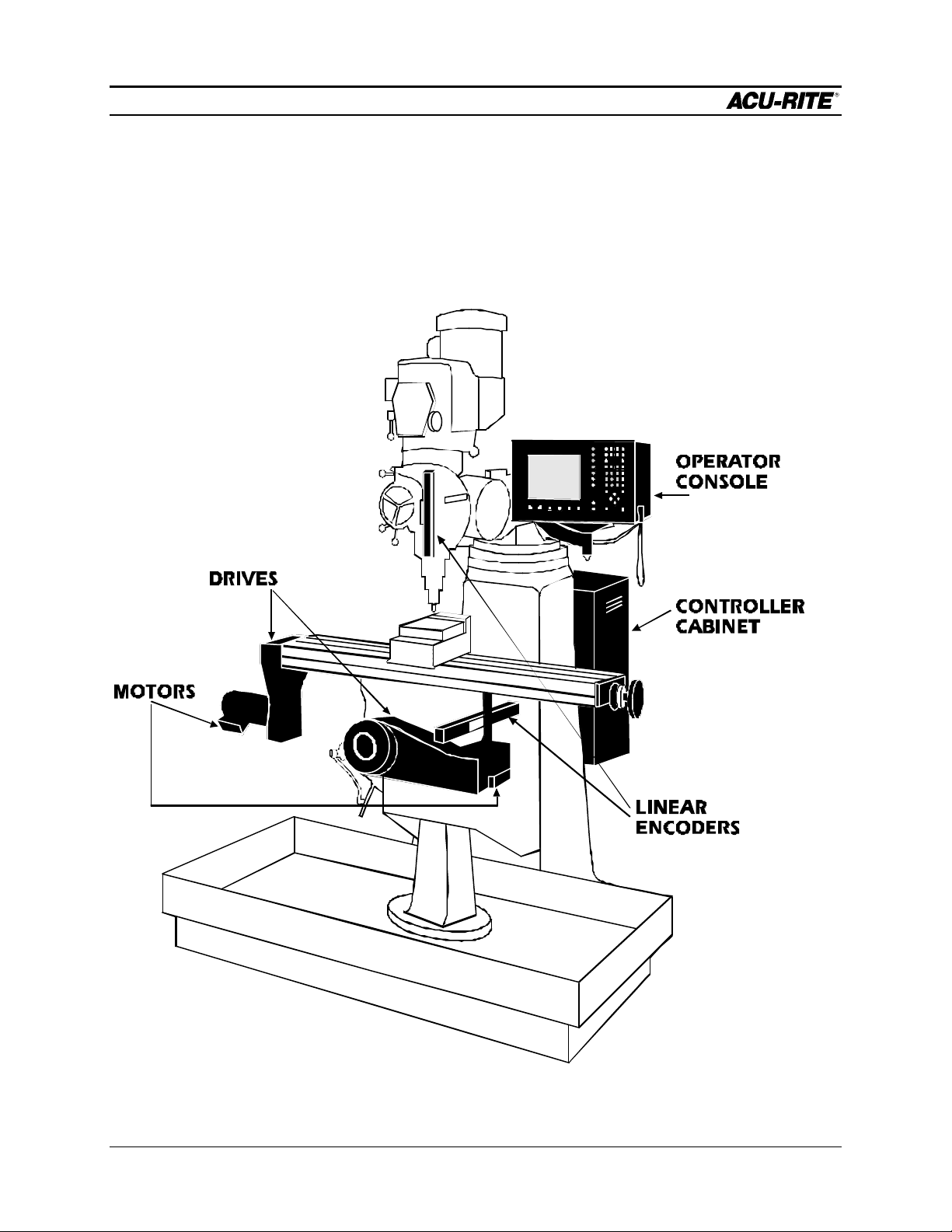
MILLPWR is a complete system that includes ground and hardened ball screws, powerful DC servo motors,
a user friendly operator console with a built-in floppy disk drive, a controller cabinet containing an
electronics module (which includes a large hard disk drive) and a motor control module. The system is
closed-looped with positioning feedback provided by the use of ACU-RITE’s precision glass scales
(2µm/.0001” resolution).
MILLPWR utilizes a conversational, menu prompted format that makes it easy for you to learn and quick for
you to program. No prior programming experience or training is necessary. All you have to do is simpl y
enter part dimensions directly from the print. MILLPWR automatically calculates the tool path... with
immediate part view graphic feedback providing program verification. MILLPWR’s intuitiveness allows you
to learn how to operate MILLPWR and begin making parts, and profits, in a matter of hours.
MILLPWR is backed by a comprehensive 1-year warranty, with nationwide support provided by a factory
trained and certified distribution network.
Thank you for choosing ACU-RITE. We’re confident you’ll be more than glad you did.
Sincerely,
ACU-RITE INC.
also maximizes your throughput by significantly reducing set-up time, scrap and
Page 2

MILLPWR System Setup Access Code
An access code must be entered before the system setup
parameters can be set or changed. This prevents inadvertently
resetting parameters.
IMPORTANT
The access code is 8891
Refer to section 7, “System Setup.”
IMPORTANT
Supervisors may wish to remove this page from the
MILLPWR manual after initially setting up the system
parameters. Keep it in a safe place for future use.
387900-970 Edition E
Page 3

TABLE OF CONTENTS
Section 1. Introduction
System Overview...........................................................................1-1
Machine Layout ...................................................................1-1
Keypad Layout ....................................................................1-3
Screen Layout ......................................................................1-4
Saving, Backing Up, and Creating Directories
For Programs...............................................................1-5
Emergency Table Stop Button ..............................................1-5
Conventions ..................................................................................1-6
Axis Conventions ....................................................................1-6
Absolute/Incremental ...............................................................1-7
Section 2. DRO
Start-up ........................................................................................2-1
Power Up ............................................................................2-1
Finding Home ......................................................................2-2
DRO Functions .............................................................................2-3
Reset an Axis .......................................................................2-3
Inch -Metric ..........................................................................2-3
Move Table .........................................................................2-3
Establishing a Datum ............................................................2-4
Using a Probe ......................................................................2-5
One Time Milling Functions ..................................................2-6
Section 3. Programming
Programming Considerations .........................................................3-1
Depth of Cut ........................................................................3-1
Tool Offset ..........................................................................3-1
“From” and “To” Points .......................................................3-2
Datum Selection ...................................................................3-2
Absolute and Incremental Dimensions ...................................3-2
Operation Manual i MILLPWR
Page 4

TABLE OF CONTENTS
Continuous Milling ................................................................3-3
Creating a Program .......................................................................3-4
The View Key .....................................................................3-6
Running a Program ........................................................................3-6
Setting the Datum .................................................................3-6
Testing Your Program ..........................................................3-7
Pressing the GO Key ...........................................................3-8
Feed Rate Override .............................................................3-9
Machining to Zero ................................................................3-9
Program Functions ......................................................................3-11
Accessing the Load, Save, Delete, and
Backup Options ........................................................3-11
Saving a Program ...............................................................3-12
Directories .........................................................................3-14
Creating a Directory ..................................................3-14
Selecti ng a Directory .................................................3-17
Deleting a Directory ..................................................3-19
Other Program Functions ...................................................3-20
Naming a Program ....................................................3-20
Deleting a Program ....................................................3-21
Backing Up a Program ..............................................3-22
Loading a Program ....................................................3-24
From MILLPWR’s internal hard disk drive ..........3-24
From a 3 ½” floppy disk .....................................3-26
From your PC .....................................................3-27
Section 4. Demonstration
A Demonstration Program .............................................................4-1
Selecting the Datum ..............................................................4-1
Beginning the Program ..........................................................4-1
Selecting a Tool ...................................................................4-2
Milling the Workpiece Contour .............................................4-3
MILLPWR ii Operation Manual
Page 5

TABLE OF CONTENTS
Programming the Bolt Circle ...............................................4-13
Programming the Pocket ....................................................4-15
Saving Your Program .........................................................4-17
Testing Your Program ........................................................4-17
Running the Program ..........................................................4-18
Tool Changes .....................................................................4-20
Clearing the Program ..........................................................4-20
Section 5. Program Steps
Sample Milling and Drilling ............................................................5-1
Set Tool ...............................................................................5-1
Positioning/Drill ....................................................................5-1
Mill Line ..............................................................................5-2
Mill Arc ...............................................................................5-2
Blend ...................................................................................5-3
Rectangular Milling Functions ........................................................5-4
Pocket .................................................................................5-4
Rectangular Frame ...............................................................5-5
Face ....................................................................................5-6
Slot ......................................................................................5-7
Circular Milling Functions ..............................................................5-8
Circular Pocket ....................................................................5-8
Circular Frame .....................................................................5-9
Ring ...................................................................................5-10
Hole Patterns ..............................................................................5-11
Row of Holes .....................................................................5-11
Hole Frame and Hole Array ...............................................5-12
Bolt Circle .........................................................................5-13
More Steps .................................................................................5-14
Repeat ...............................................................................5-14
Rotate ................................................................................5-15
Mirror ................................................................................5-16
Operation Manual iii MILLPWR
Page 6

TABLE OF CONTENTS
Custom Pocket ..................................................................5-17
Engrave .............................................................................5-18
Explode .............................................................................5-20
Section 6. Calculator
Four Function Arithmetic ...............................................................6-1
Trig and Math Functions ................................................................6-1
Geometry Calculator .....................................................................6-4
Why We Need a Geometry Calculator .................................6-4
Working with the Geometry Calculator .................................6-5
Example Problem ..........................................................................6-7
Strategy ...............................................................................6-7
Starting the Program .............................................................6-7
Entering the Lines .................................................................6-8
Finding the Arc ..................................................................6-10
Finding the Points of Tangency ...........................................6-12
Returning Features ..............................................................6-13
Section 7. Setup
Inch or Metric ......................................................................7-1
Operator Setup .............................................................................7-2
Tool Library ..................................................................................7-2
Scale Factor .................................................................................7-3
Display Options ............................................................................7-4
Touch Probe .................................................................................7-5
Feed Rate Settings ........................................................................7-5
System Setup ................................................................................7-6
Protection ............................................................................7-6
Error Compensation .............................................................7-7
Encoder Direction ................................................................7-8
Serial Port ............................................................................7-9
MILLPWR iv Operation Manual
Page 7

TABLE OF CONTENTS
Section 8. Remote Storage
Equipment .....................................................................................8-1
Choosing a Serial Cable ................................................................8-1
Connecting MILLPWR to Your PC ...............................................8-2
Installing the Remote Storage Program ...........................................8-3
Operation Manual v MILLPWR
Page 8

TABLE OF CONTENTS
Setting the PC’s COM Port and BAUD Rates ...............................8-4
Common Error Messages ..............................................................8-5
Section 9. Troubleshooting Guide
Introduction ..................................................................................9-1
Using the Table .............................................................................9-1
Table ............................................................................................9-2
MILLPWR vi Operation Manual
Page 9

TABLE OF CONTENTS
387900-167 Software Version 1.3 Ed G
Operation Manual vii MILLPWR
Page 10
INTRODUCTION
MILLPWR
INTRODUCTION
System Overview
Machine Layout
Operation Manual Page 1-1
Page 11
INTRODUCTION
MILLPWR
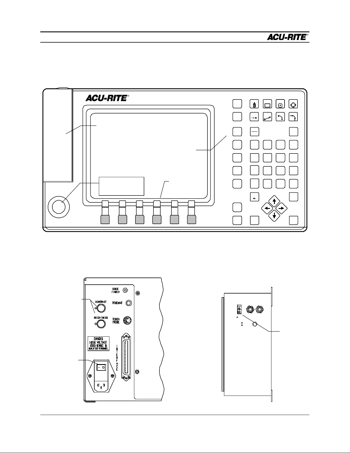
Front View of Operator Console
TABLE
STOP
INFO
SET
UP
TOOL
CIRCLE HOLES
RECT
ARC
LINEPOS BLEND
Floppy
diskette inside
Emergency
Keypad
Softkeys
VIEW
PGM
DRO
CANCEL
USE
ABS
INC
4 5 6
1
2
.
0
CALC
987
3
+/-
TABLE STOP
FEED
FEED
DEL
+
STOP GO
-
ENTER
Rear of Operator Console Side of Controller Cabinet
/
X
-
+
Contrast and
brightness
knobs --adjust
them for best
picture
Main power
switch. Use this
to turn MILLPWR
on and off.
Power
Switch for
console only
(just leave it
on)
Page 1-2 Operation Manual
Page 12
INTRODUCTION
MILLPWR
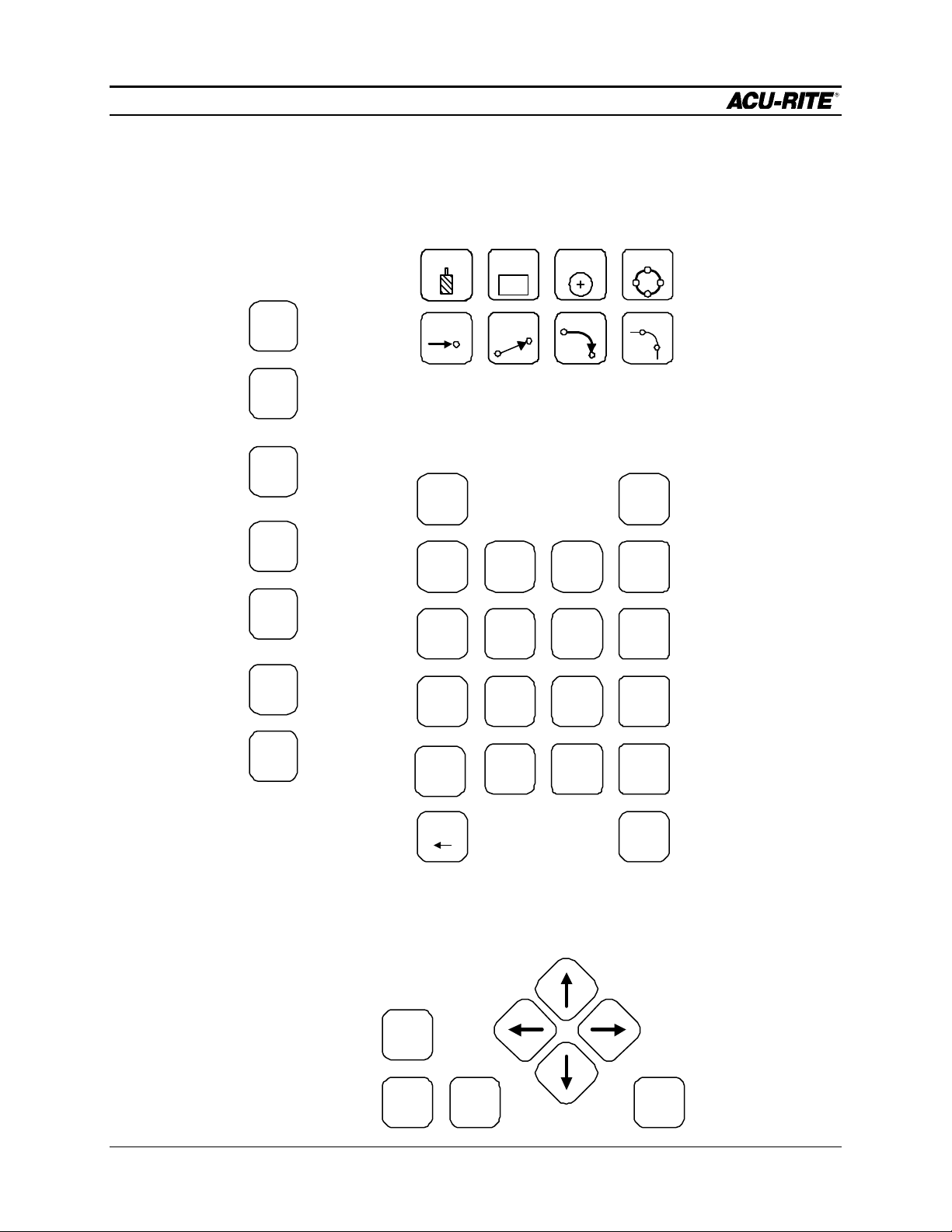
Keypad Layout
These let you set up
the MILLPWR, get
information about
what you are doing,
switch between
program (PGM) and
DRO, and “USE” the
milling functions as
steps in a program.
Main
Function Keys
INFO
SET
UP
VIEW
PGM
Milling Functions
TOOL RECT CIRCLE
POS
LINE
ARC BLEND
Numeric Keypad
and Calculator
ABS
INC
7 8
9
HOLES
CALC
/
With these keys, you define
the operations you want
MILLPWR to perform.
These operations end up
as “steps” in a program, or
you can run just one of
them at any time.
DRO
CANCEL
USE
Press GO to run your program, and
STOP to stop it. The FEED keys let
you adjust the cutting speed on the
fly.
4 5
6
1 2 3
.
DEL
0
Cursor and Motion Control Keys
FEED
+
FEED
-
+/-
ENTER
X
+
Enter all numerical
values with these
keys. When you’re
entering dimensions,
you can specify
absolute or incremental.
-
The handy 4-function
calculator can be used
at any time. Trig and
geometry assistance
is available with a press
of the CALC key.
GOSTOP
Operation Manual Page 1-3
Page 13

INTRODUCTION
MILLPWR
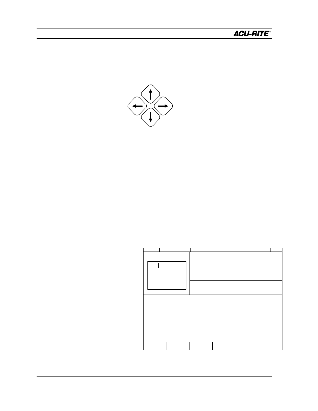
The cursor keys help you
navigate around the screen
while you are using
MILLPWR.
Page 1-4 Operation Manual
Page 14
INTRODUCTION
2 3 4
MILLPWR
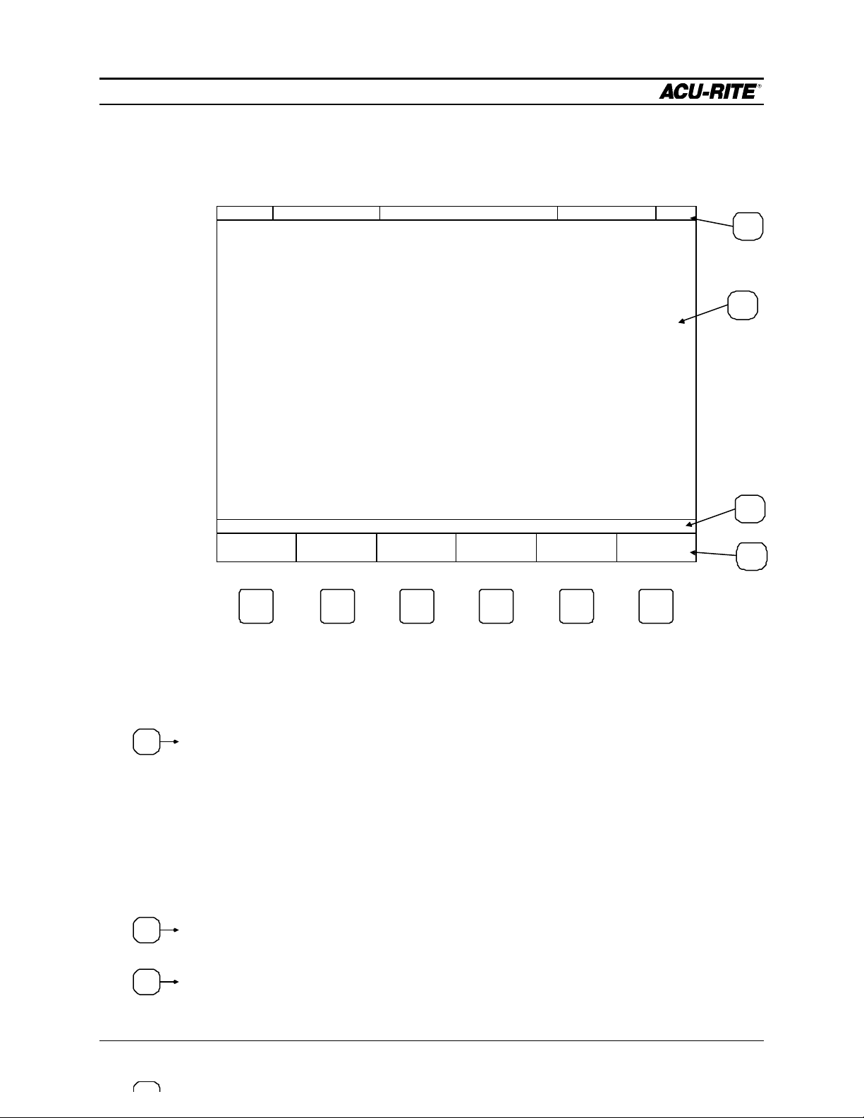
Screen Layout
The MILLPWR display screen is divided into four sections.
SERVO
FEED 0 100%
OFF
ZERO X ZERO Y ZERO Z
SCALE 1.0000TOOL:
DATUM
MOVE
TABLE
INCH
1
2
3
4
Status bar - displays the servo motor status (on/off), feed rate, current tool, scale, and
inch/mm display view.
Information screen - displays information for the job being performed.
• Used as a readout, the screen will display the current location for each axis.
• When programming, a list of milling operations and part view graphics will
be displayed.
• To calculate data geometrically, lines and arcs can be constructed and
displayed.
Message line - operator prompts and messages will appear here.
Softkeys - variable key functions appear here; functions are selected by pressing
the hard key directly below the softkey message.
Operation Manual Page 1-5
Page 15

INTRODUCTION
MILLPWR
Saving, Backing Up, and Cr eating Directories for Programs
When you begin to create programs for your MILLPWR to run, you can save your
If you're writing a
long program,
don't wait until
the end to save
your work.
Frequent saving
reduces the risk
of losing work
due to a power
interruption.
programs in any of three places—on MILLPWR’s internal hard disk drive, on a 3
½” floppy disk, or on your PC’s hard disk drive. Saving your work means it will
not be lost if the MILLPWR is turned off or if there is a power failure.
Your MILLPWR is also equipped with a backup feature that enables you to make
duplicate copies of your saved programs. We recommend backing up your work
as an extra precaution against accidental deletions, hard disk drive failures, or other
problems that may prevent you from recovering your original files. Backing up your
programs takes only a few moments—and will save you valuable time if a problem
does occur.
And as you save and back up your programs, you can neatly organize them in any of
the three default directories (“MILLPWR,” “A:,” and “REMTSTOR”) or in
personalized directories you create on your own.
For more details about how to save programs, back up files, and create directories,
refer to the Programming section.
Note: Before you save or back up programs on your PC’s hard disk drive, refer to the
Remote Storage and System Setup sections for setup instructions.
Emergency Table Stop Button
The large red button on the front of the MILLPWR operator console is the emergency
TABLE STOP. In the event of a malfunction or programming error, press the emergency
TABLE STOP button to disengage the servo motors. Disengaging the servos will
cause all table movement to stop.
WARNING
Pressing the emergency TABLE STOP button will NOT
stop the rotation of the cutting tool unless your machine
has been specifically wired to do so. Therefore, in the
event of an emergency, if your machine has not been
wired to stop the rotation of the cutting tool, be prepared
to raise the quill in addition to pressing the emergency
TABLE STOP button.
Page 1-6 Operation Manual
Page 16
INTRODUCTION
MILLPWR
Conventions
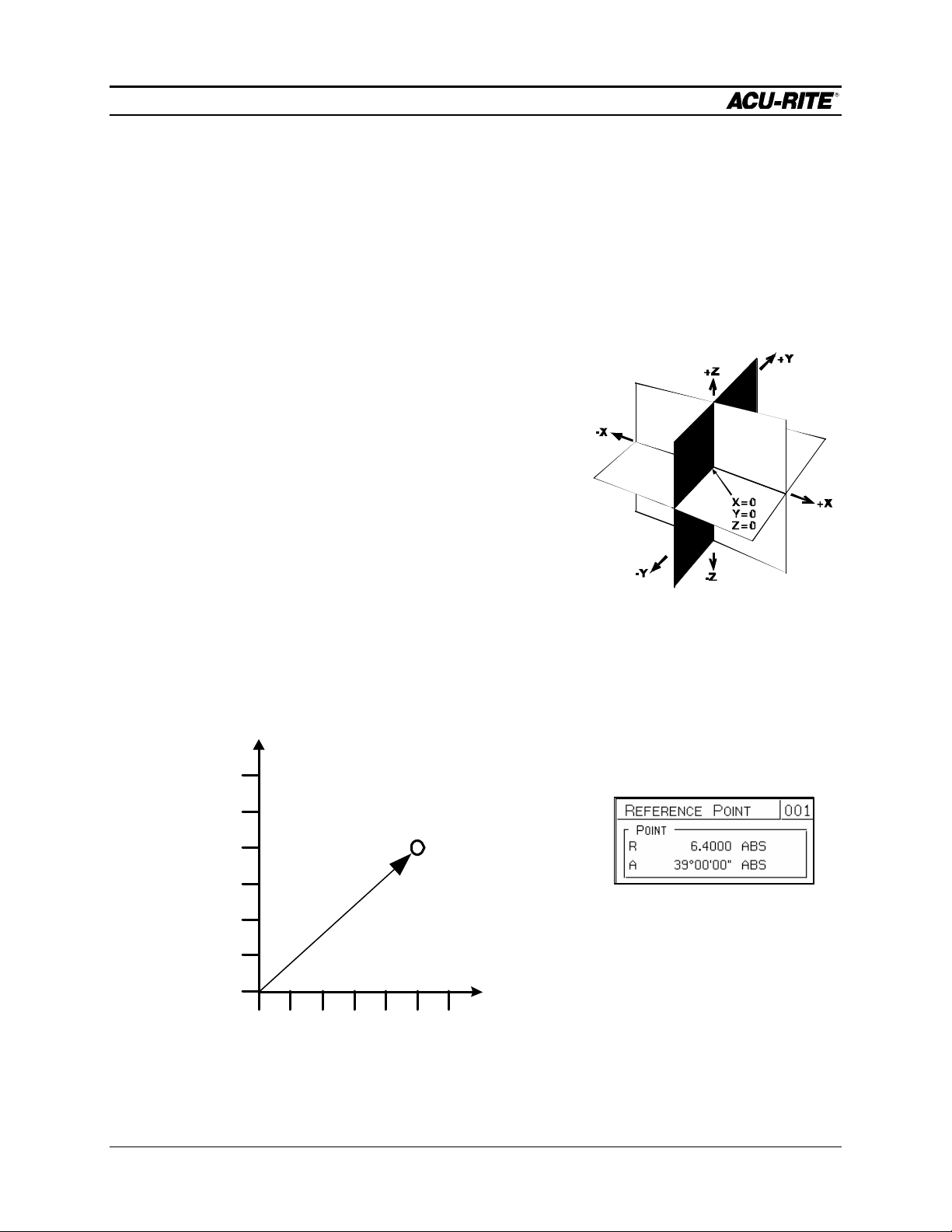
Axis Conventions
Cartesian Coordinates
When programming a part using MILLPWR, table movement and tool motion are
determined by the use of positive or negative numbers. MILLPWR has been factory set
with the following positive and negative directions for X, Y, and Z:
X-axis: the table will move to the left, with tool
motion to the right, for positive positions.
Y-axis: the table will move toward you while tool
motion is away from you for positive positions.
Z-axis: quill movements up (away from the table
surface) are for positive positions.
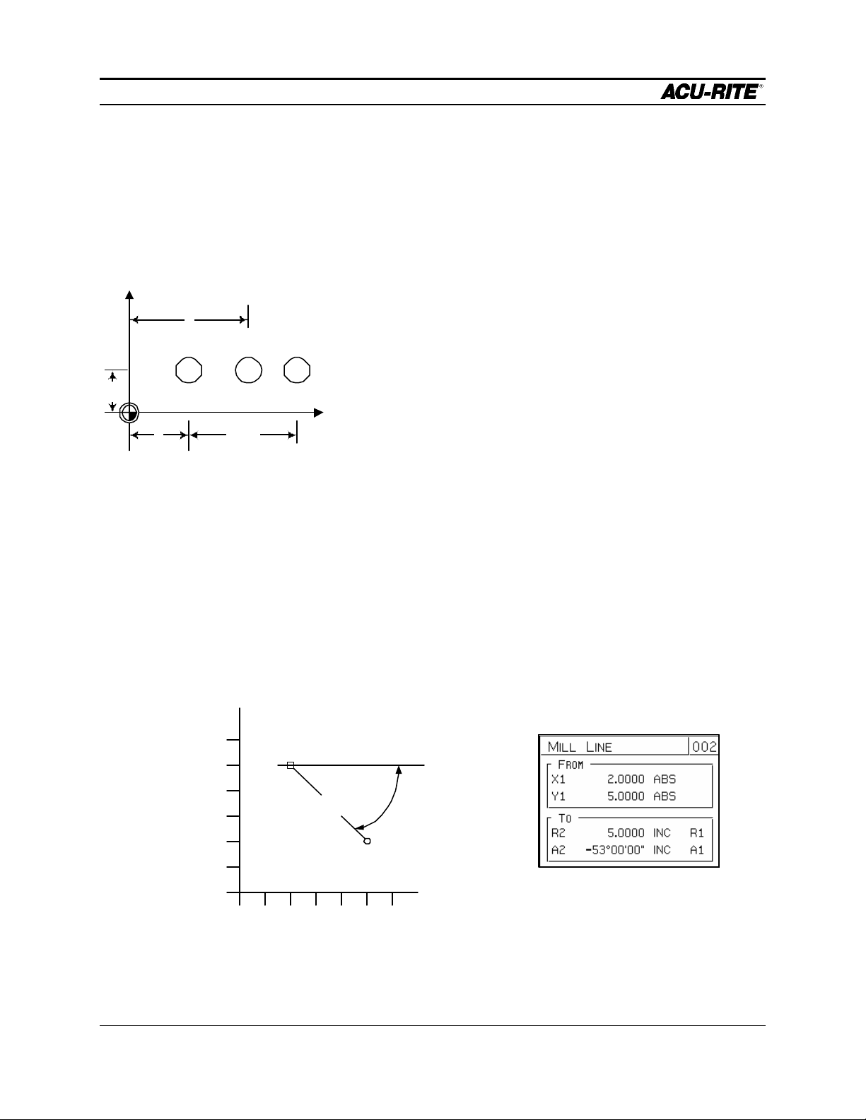
Polar Coordinates
The polar radius (R), is the distance from datum (absolute zero) to a point. The polar
angle (A), is formed by the X-axis and the radius, positive counter- clockwise. The
angle is always measured from the positive X-axis.
6
5
4
3
2
1
R=6.4
A=39°
0
1 2 3 4 5 60
Operation Manual Page 1-7
Page 17
INTRODUCTION
MILLPWR
Absolute / Incremental
Dimensions you enter from the print can be either absolute or incremental.
Absolute dimensions are measured from the datum which is the workpiece zero.
Incremental dimensions are measured from one point to another.
+Y
1.5
4
A B C
2
3.625
absolute coordinates of a point.
Both absolute and incremental dimensions can be used on the same workpiece. For
example, Hole C has the dimensions X = 3.625 INC from hole A, Y = 1.5 ABS.
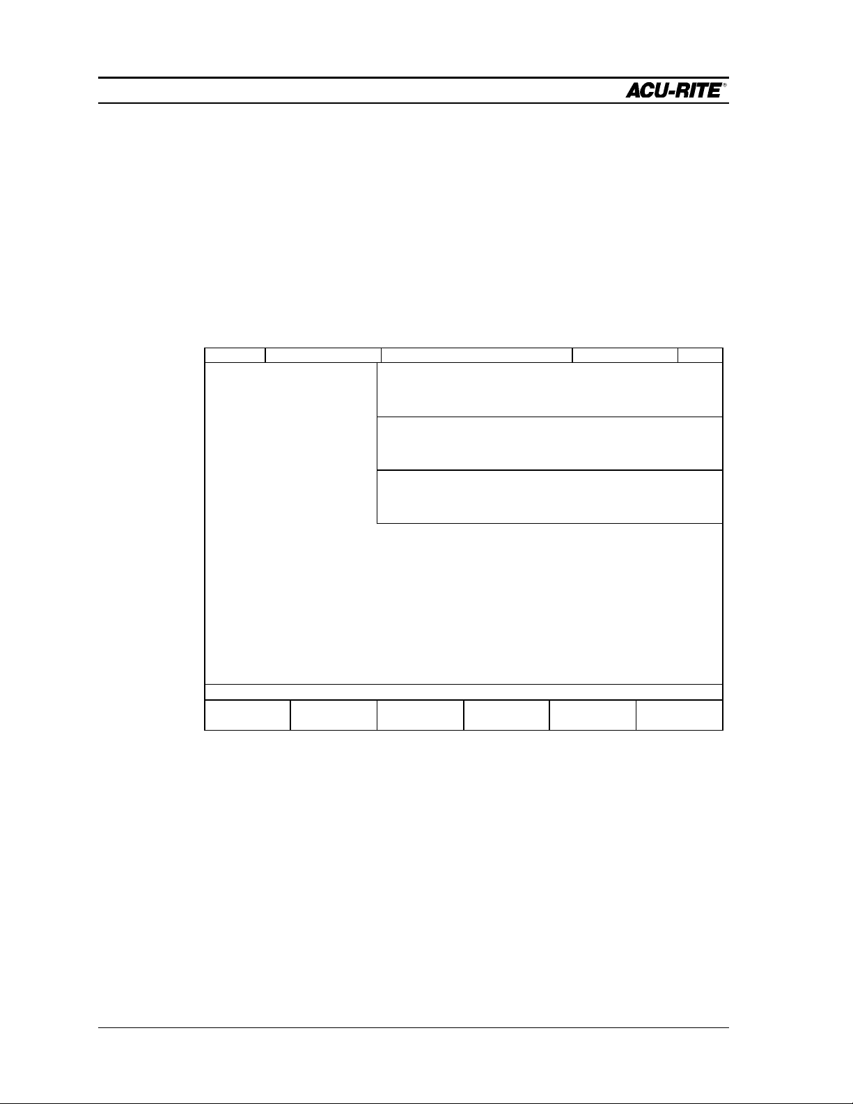
Example: Polar and Incremental
Here is how to enter the angle of a line:
If your drawing provides the angles from one end, you need to use polar and
incremental. The end of the line is measured incrementally from the beginning of the
line.
+X
Holes A and B are dimensioned as absolute, but hole C is
dimensioned incrementally from A.
When entering these dimensions in the MILLPWR, we
would say:
Hole A: X = 2.000 ABS
Hole B: X = 4.000 ABS
Hole C: X = 3.625 INC from hole A
It will often be easier to describe a location in terms of
incremental dimensions than it would be to calculate the
6
5
4
3
2
1
0
P1 (From)
5.0
P2 (To)
0 1 2 3 4 5 6
- 53°
Page 1-8 Operation Manual
Page 18

INTRODUCTION
MILLPWR
Notice that if you don’t use incremental coordinates, Point 2 will be incorrect because it
will be measured from the datum instead of from Point 1.
Operation Manual Page 1-9
Page 19

INTRODUCTION
MILLPWR
BLANK PAGE
Page 1-10 Operation Manual
Page 20
DRO
MILLPWR
DRO FUNCTIONS
Start-Up
Power Up
• Make sure the power switch on the back of the Operator’s Console is on.
• Turn the on/off switch on the side of the controller cabinet ON.
After the program has loaded, the following screen will appear:
SERVO
FEED 0 100%
OFF
SCALE 1.0000TOOL:
INCH
DRO stands
for “digital
readout”.
INC
X
0.0000
INC
Y
0.0000
INC
Z
0.0000
ZERO X ZERO Y ZERO Z DATUM
This is called the “DRO” screen. It shows you the current tool position. Here you
can use several DRO functions to set up your job. In fact, you can use this as a
normal DRO when you use your machine manually.
0.0000
0.0000
0.0000
ABS
ABS
ABS
MOVE
TABLE
Operation Manual Page 2-1
Page 21

DRO
MILLPWR
Finding Home
The ACU-RITE’s ENC150 precision glass scales included with your MILLPWR
system are different from standard ENC150 glass scales because they have only
one reference mark. The reference mark will be located between five and eight
inches from the centerline of your scale. The reference mark will most likely be
found in the positive count direction for both the X and Y axes; however, it may be
found in the negative count direction depending upon how the scale(s) are mounted.
MILLPWR must find these reference marks after power-up in order to establish the
farthest table travel, so you won’t crash the table. You must find home before you
can run a program.
To find home, press the DATUM softkey, then the FIND HOME softkey. The
Once you are
familiar with where
the reference marks
are, you can use the
“MOVE TABLE”
function to get close
to them before you
press "FIND HOME".
table will move, one axis at a time, to find the reference positions.
If the table moves until it hits the hard stops and the servo motor stops, it
means the table was already positioned past the home position. Use the
handcranks to move the table away from the end and press FIND HOME
again. Should the FIND HOME softkey be pressed immediately after home has
been found, the table will move to the hard stops and the servo motors will
disengage.
DATUM is a term
for “workpiece
zero” or “absolute
zero”.
After home has been found, the DRO display will change. The absolute display
shows the tool position from the most recent datum.
Page 2-2 Operation Manual
Page 22
DRO
MILLPWR
DRO Functions
Reset an Axis
Pressing the ZERO X, ZERO Y, or ZERO Z softkey will zero the incremental position
of that axis.
You can’t change
to metric if you
have an “inch”
program active,
and vice versa.
Note that the
arrow keys will
move the table!
Inch - Metric
To change the measurement system between inches and metric units, press the
SETUP key to get the INCH and MM softkeys. Select the system you want, and
press USE NEW SETTINGS.
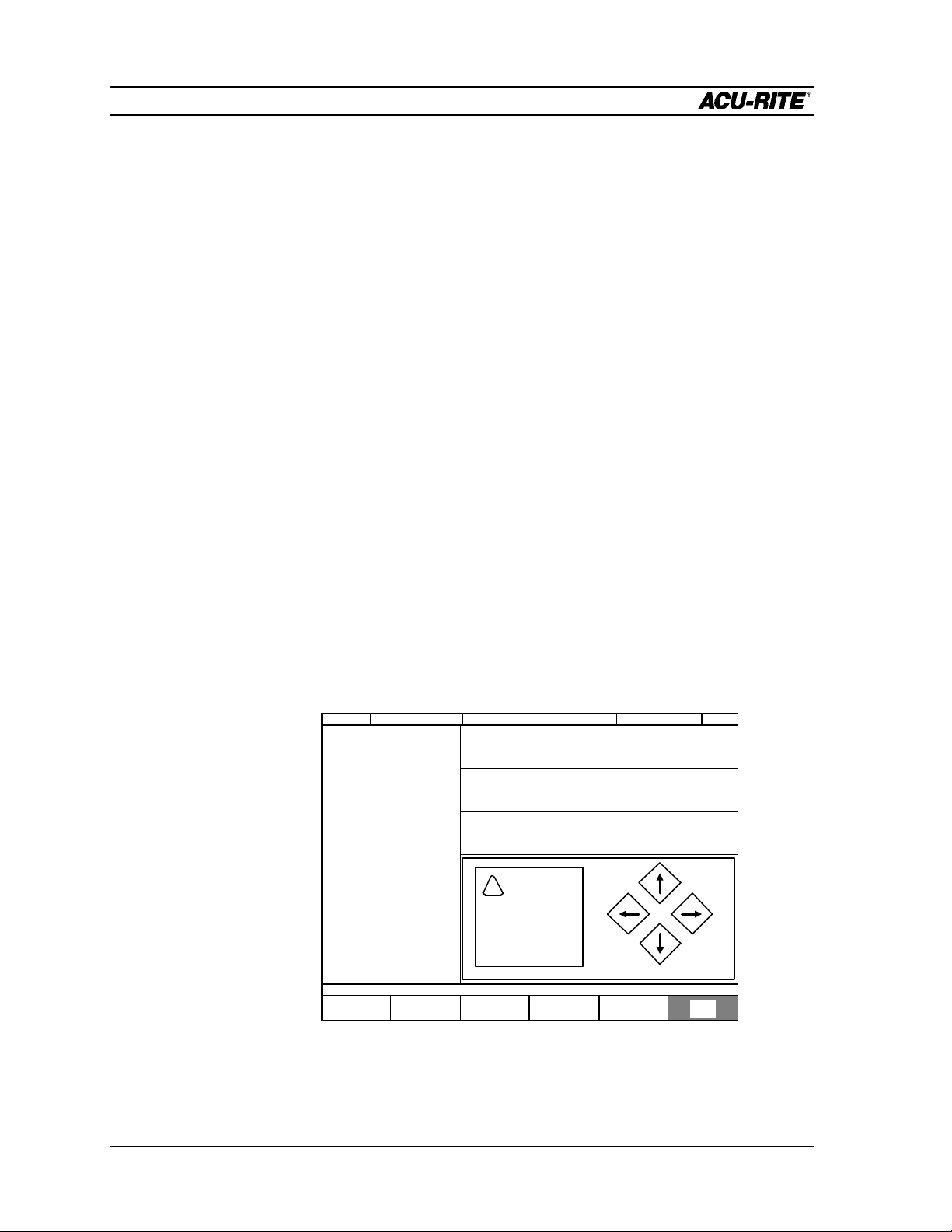
Move Table
This function lets you move the table rapidly using the arrow keys. Pressing the
MOVE TABLE softkey will caution you that the arrow keys no longer move around
the screen, but will instead move the table.
SERVO ONFEED 0 100%
X
Y
Z
INC
0.000
INC
0.000
INC
0.000
SCALE 1.0000TOOL:
0.0000
0.0000
0.0000
INCH
ABS
ABS
ABS
!
CAUTION
ARROW KEYS
WILL MOVE TABLE
PRESS CANCEL WHEN FINISHED MOVING TABLE.
MOVE
TABLE
Operation Manual Page 2-3
Page 23
DRO
MILLPWR
The table moves in the direction of the arrows. You can move in both X and Y at
the same time.
MOVE TABLE AWAY
FROM YOU
While the MOVE TABLE
It’s a REALLY good
idea to fold in the
handcrank handles
before moving the
table!
Establishing a Datum
A datum is a reference point that you establish as the workpiece zero. You need to
set a datum for each job. The location on the workpiece that is to be used as the
datum will be determined by the way the part is dimensioned on the blueprint. In
general, you should select a datum location so that you may enter most dimensions
directly, without calculations.
MOVE
TABLE
LEFT
MOVE
TABLE
RIGHT
MOVE TABLE
TOWARDS YOU
softkey is pressed, the
servo motors are on.
Press it again to turn them
off.
The datum position is not lost at power-down, so you can quit in the middle of a job
at night and easily resume it the next morning.
The simplest datum location to set is where you can position the tool exactly at that
location in all three axes.
• Position the
workpiece so that the
datum point is directly
beneath the tool. This
point might be a
corner, the center of a
bolt hole pattern, etc.
SERVO
X:
Y:
Z:
OFF
FEED 0 100%
SET DATUM
X
Y
Z
INC
0.0000
INC
0.0000
INC
0.0000
SCALE 1.0000TOOL:
0.0000
0.0000
0.0000
• Press the DATUM
softkey and the Set
Datum entry form will
appear.
• Press the X=0, Y=0,
and/or Z=0 softkey(s)
ENTER THE NEW ABSOLUTE POSITION OF THE TOOL CENTER.
X = 0 Y = 0 Z = 0
FIND
HOME
USE
PROBE
MOVE
TABLE
to establish workpiece zero.
INCH
ABS
ABS
ABS
• Press USE to lock in the workpiece zero.
Page 2-4 Operation Manual
Page 24
DRO
MILLPWR
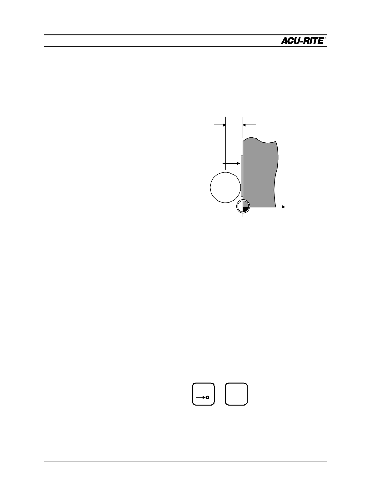
If you can’t position the tool center right at the datum, you’ll need to enter a value
for each axis. The value to use is the absolute position of the tool center from the
new datum. For one axis at a time, position the tool to a known location, such as
the edge of the workpiece. Without moving the tool, enter the desired location of
the tool center and press ENTER. Then move to position the next axis. When all are
entered, press USE.
DISTANCE TO
The MILLPWR
calculator helps a lot
here---To set the
datum for the X axis,
enter:
0.3875/2+.005. Then,
since the tool center is
left of the datum,
change the sign.
.005 SHIM
0.3875
TOOL
ENTER
+
While you are setting the datum, you can use the MOVE TABLE softkey to help you
with long moves.
Using A Probe
You may use a touch probe or edge finder to get very accurate edge locations.
Make sure the diameter of the probe is correct (it’s found in the SET-UP list).
Install the probe and connect it to the back of the Operator Console. Then, for one
axis at a time, enter the absolute position of the edge to be touched into the datum
form, press the USE PROBE softkey, and move the table slowly until the probe
touches the workpiece. When the probe touches, the USE PROBE softkey will
release. Press the USE key to set the absolute position of each axis.
TIP:
Right after you find
home, you
can move quickly to
your previous datum
using the position
function:
POS
GO
Operation Manual Page 2-5
Page 25

DRO
MILLPWR
One Time Milling Functions
Any of the milling functions, except BLEND, can be used “one time” without creating
a program. Press the desired milling function key, fill in the information, and press
GO.
The information for each function will be remembered for the next time you use it.
Each function is described in the Program Steps section.
For many of the milling functions, such as a pocket, you will need to set the proper
tool diameter. You can use the TOOL key as a one-time function to do this.
Page 2-6 Operation Manual
Page 26
PROGRAMMING
MILLPWR
PROGRAMMING
Programming Considerations
Depth of Cut
Since the vertical Z-axis is not controlled by a servo motor, you must make changes to
the depth of cut manually.
You don’t have to program the depth, but if you do, MILLPWR will preset the
programmed value into the DRO for you. Then, when it’s time, MILLPWR will show
you the DRO and ask you to set the depth.
If you are not programming depth, leave it set to 0.
Tool Offset
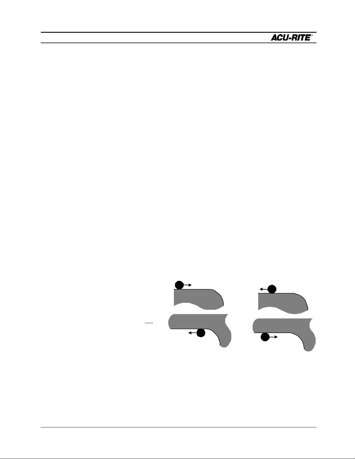
With MILLPWR, you never have to worry about the actual tool path. Because of
MILLPWR ’s tool radius compensation capability, you program only the actual part
dimensions. When you program a line, arc, or frame, use the TOOL OFFSET field to tell
MILLPWR which side of the cut you want the tool to be on.
Picture yourself standing behind the tool as it is moving. If the tool is on the left of the
workpiece, use “left” offset. If the tool is to the right of the workpiece, use “right” offset.
By using left and right offsets,
you can program the
LEFT OFFSET
RIGHT OFFSET
dimensions of the part as
found on the blueprint.
MILLPWR will take care of
all cutter radius
compensation. You do not
have to program the tool
path.
If you use “center” offset, the
programmed dimensions are
for the center of the tool.
For some milling functions, like Frame and Arc, “inside” and “outside” offsets help you
visualize where the tool is.
Operation Manual Page 3-1
Page 27
PROGRAMMING
MILLPWR
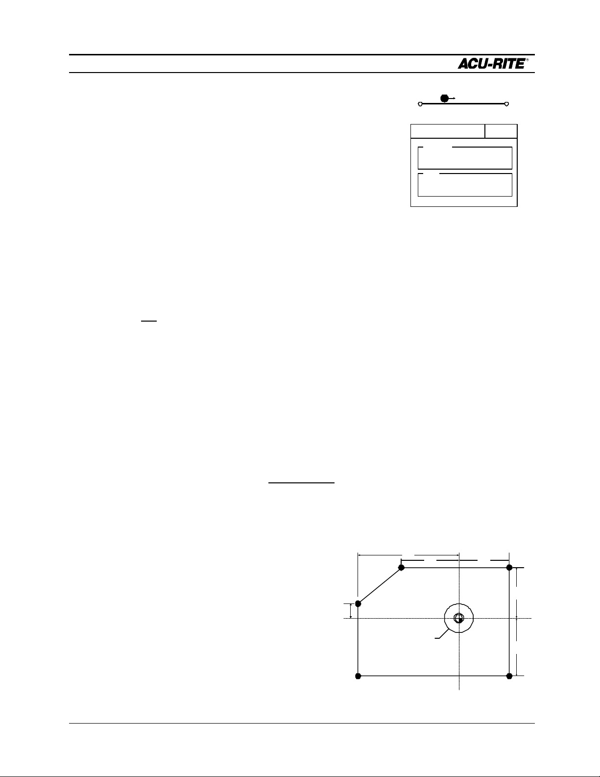
“From” and “To” Points
MILLPWR lines and arcs are defined by both FROM and
TO points. MILLPWR will automatically go to the start
point before it asks you to set the depth.
Datum Selection
The datum is the point where all absolute dimensions are measured from. You must look
at the blueprint of the part and decide what to use as a datum. You should pick a point
which will let you enter most of the dimensions directly, without calculations. However,
any point you select will give the same results.
FROM TO
FROM
X1 ABS
Y1 ABS
TO
X2 ABS
Y2 ABS
Absolute and Incremental Dimensions
To help you enter dimensions directly from the blueprint, MILLPWR allows direct entry
of both absolute and incremental dimensions. Any dimension measured from the point
you select as the datum is called absolute.
A dimension measured from any other point is called incremental. This “other point” is
called the incremental reference point.
For the part drawn below, if we put the datum in the center of the hole (point F), all
dimensions are absolute.
Point X Y
A -7.123 ABS -3.936 ABS
B 3.421 ABS -3.936 ABS
C 3.421 ABS 3.603 ABS
D -4.893 ABS 3.603 ABS
E -7.123 ABS 1.011 ABS
1.011
7.123
D
E
2.96 DIA
THRU HOLE
3.4214.893
F
C
3.603
3.936
F 0.00 ABS 0.00 ABS
A B
Page 3-2 Operation Manual
Page 28
PROGRAMMING
MILLPWR
If we use point A as our datum, many of the given dimensions are incremental because
they are measured from the incremental reference point F and not from the datum.
Point X Y
MILLPWR will
display marks to
the right of each
program step
number for
continuous
contours.
7.123
D
A 0.00 ABS 0.00 ABS
B 3.421 INC F 0.00 ABS
C 3.421 INC F 3.603 INC F
D -4.893 INC F 3.603 INC F
E 0.00 ABS 1.011 INC F
F 7.123 ABS 3.936 ABS
1.011
E
2.96 DIA
THRU HOLE
A
Continuous Milling
When you program a continuous contour made up of lines and arcs, MILLPWR
will mill the contour without stopping. MILLPWR will detect a continuous contour
automatically. There are no special keypresses or different functions to learn.
For lines and arcs to be continuous, they must:
FROM TO
• have the same Z depth,
3.4214.893
F
C
3.603
3.936
B
FROM
• be cut with the same tool,
• be cut on the same side,
TO
• and, of course, they must “touch”--the end of one
must be the same as the start of the next.
When you follow one line (or arc) with another, MILLPWR assumes that you want them
to be connected. It automatically fills in the FROM point, Z depth, and tool offset. All you
have to do is fill in the TO point, and press USE.
You can have different feedrates within a continuous contour by entering the feedrates
you want in each step of the contour.
Operation Manual Page 3-3
Page 29

PROGRAMMING
MILLPWR
Creating a Program
Press the PGM key, and the following program screen appears.
SERVO
OFF
CURRENT PROGRAM
PROGRAM
FUNCTIONS
FEED 0 100%
END OF 0
CLEAR
PROGRAM
EXPLODE
MORE
STEPS
SCALE 1.0000TOOL:
RUN
OPTIONS
INCH
You create a program by creating a list of milling steps to be performed. As you add to
your list, each step will be drawn immediately on the screen so you can see a picture
of your part in progress.
Program
Step
Listing
• To enter a milling step, press the appropriate milling function key. The function
you select will appear in the program listing, and you can enter the information
SERVO
OFF
CURRENT PROGRAM
001 SET TOOL
002 MILL ARC
X
FEED 0 100%
2 OF 2
MILL ARC 002
FROM
X1 ABS
Y1 ABS
TO
X2 ABS
Y2 ABS
DEPTH
Z ABS
RADIUS
DIRECTION
CCW
TOOL
0.500 DIAMETER
FL END ML
CENTER OFFSET
10FEED IPM
TEACH
POSITION
TYPE
SCALE 1.0000TOOL:
INCH
Enter
information
about the arc
into this form.
MOREPOLAR
Page 3-4 Operation Manual
Page 30
PROGRAMMING
MILLPWR
describing the step into the form.
• After entering all the data for a step, press the USE key to accept the data. This
updates the picture and moves down for the next step.
SERVO
OFF
CURRENT PROGRAM
001 SET TOOL
002 MILL ARC
PROGRAM
FUNCTIONS
FEED 0 100%
END OF 2
CLEAR
PROGRAM
EXPLODE
MORE
STEPS
SCALE 1.0000TOOL:
RUN
OPTIONS
INCH
• To change a step, use the arrow keys to move to the step and press USE or ENTER.
When you have made your changes, press USE to put the changed step back into
the program.
• To delete a step, move to the step and press the DEL key.
• To insert a step, move to where you want the new step to go, and press the new
milling function key.
If you decide not to use a milling function that you have selected, press the CANCEL key.
In addition to the milling functions, the MORE STEPS softkey lets you pick from a
number of other useful steps, such as REPEAT and ROTATE. All steps are described in
the Program Steps section.
Operation Manual Page 3-5
Page 31

PROGRAMMING
MILLPWR
The View Key
If you need to see more detail of the picture, press the VIEW key. This brings up the
following softkeys:
ZOOM
IN
ZOOM
OUT
RESTORE
The ZOOM IN softkey magnifies the picture, and the arrow keys move the picture up,
down, left, and right. The ZOOM OUT softkey will de-magnify the picture, and the
RESTORE softkey brings back the original view.
Press VIEW again (or CANCEL) to see the normal programming softkeys.
Running a Program
When you are ready to run a program, you must make some preparations. This includes
fixturing the workpiece, setting or finding the datum, and deciding on the tools to use.
Setting the Datum
From the DRO, select the DATUM softkey. There are two ways to find the datum:
“touching off” with a tool and using a touch probe or edge finder.
To touch off with a tool:
• Move the tool to touch the edge of the workpiece.
• Key in the new absolute position of the tool center in this axis. Be careful of the
polarity.
• Before you move the table, press ENTER or an arrow key. At this time, MILLPWR
remembers the scale position and will use it to determine the datum for this axis.
• Repeat for the second and, if desired, the third axis. Be sure to press ENTER
For the last axis, you
can press USE
instead of ENTER.
while the tool is in position.
• Press USE to establish the datum.
Page 3-6 Operation Manual
Page 32

PROGRAMMING
same time is
MILLPWR
Testing Your Program
Before you run your program, you might want to test it for things like tool path,
directions, feed rates, and sequence of operations. MILLPWR provides several runtime options to assist you. In the program screen, press RUN OPTIONS to display the
following softkeys.
Using DRY
RUN and
GRAPHICS
ONLY at the
especially
handy.
SINGLE
STEP
DRY
RUN
GRAPHICS
ONLY
MANUAL
POSITIONING
DISABLE
LOOK AHEAD
RUN
OPTIONS
Press any key to activate the option; press it again to release it.
SINGLE STEP
Normally, a continuously milled contour will be cut without stopping. With
single step activated, MILLPWR will stop after each step.
DRY RUN
With this activated, MILLPWR will run your entire program at high speed and
without stopping for anything. You can follow the sequence of steps and see if
the part fits entirely on the workpiece. The dry run speed is determined in
SETUP.
GRAPHICS ONLY
With this activated, the program is run normally, except that the table does not
move. You can see all normal feedrates, tool changes, and so on.
MANUAL POSITIONING
Activate this option if you want to move the table by hand. The MILLPWR acts
just like a programmable DRO. Each target position is preset into the DRO,
and you are prompted to operate the table by hand.
DISABLE LOOK AHEAD
Normally, each cut in a contour is compared to every other cut to determine if
the tool will interfere with the part. This is called look ahead. If you press the
DISABLE LOOK AHEAD key, your program will run without doing this. Except
for custom pockets, selecting this option will make the tool path calculation much
faster.
Operation Manual Page 3-7
Page 33

PROGRAMMING
MILLPWR
Pressing the GO Key
To run a program, with or without any of the run options, move to step 1 and press GO.
Most MILLPWR program steps will cause the tool to move rapidly to the start point of
the step. You then set the tool to the proper depth, press GO, and MILLPWR performs
the action required for the step.
Before any rapid move, MILLPWR will display a warning message that the table is about
to move at high speed and that you should check for tool clearance:
ATTENTION
!
RAPID MOVE
RAISE QUILL
PRESS "GO"
.WARNING
Whenever you are about to run a
program, be sure the handcrank handles
are recessed. Rapid spinning of the
manual handwheels could cause injury.
When the GO key is pressed again, the table will move in a straight line to the new
position where you will be asked to drill or set the tool to the desired depth.
ATTENTION
!
Z AXIS
SET TO
0.0000
PRESS "GO"
Page 3-8 Operation Manual
Page 34

PROGRAMMING
MILLPWR
The remote button
acts as STOP if you
are going and as
GO if you are
stopped.
immediately.
If you use the STOP key, the following prompt will appear:
During any rapid or feed move, you may press the STOP key or the emergency
TABLE STOP button to disengage the power feed for any reason. This will stop
the table motion but will not stop the rotating cutting tool unless your
machine has been specifically wired to do so.
If you press the emergency TABLE STOP button, the program stops running
ATTENTION
!
PAUSE
PRESS "GO"
To move quickly to a
step, key in its number
(look in the message
bar), and press
ENTER.
amount for each keypress.
The override percentage is shown next to the FEED rate in the status bar at the top of the
screen. An override percentage of 100% means that actual feed rates will be at 100% of
the programmed feed rates. If the override percentage is 50%, actual feed rates will be
half of programmed values.
You can press the feedrate override keys at any time, even while the machine is moving.
Machining to Zero
Press GO again when ready to continue running, or STOP to stop running the
program.
To re-start a program, move to the step you wish to start with, and press GO.
MILLPWR will always go to the beginning of a step, even if it had been started.
Feed Rate Override
The FEED+ and FEED- keys will change the override percentage by a certain
MILLPWR is factory set in a distance to go display view. This way, any dimension you
have programmed will be “preset” into the DRO display. Every move will start at the
preset value and end at zero.
Operation Manual Page 3-9
Page 35

PROGRAMMING
SET TO
MILLPWR
If you have programmed a Z depth, when it is time for you to position the Z axis,
MILLPWR will preset the depth value into the DRO Z-axis, and the following Z- axis
prompt will appear:
ATTENTION
!
Z AXIS
SET TO
0.000
PRESS "GO"
Move the quill until the absolute Z display is zero.
If you wish, you can set MILLPWR to the incremental travel display view (see System
Setup). In this view, every move will start at 0.000 and end at the programmed value.
For example, if you have programmed a depth of -0.500, when it’s time to move the
quill, the Z-axis display will show the current tool position, and the prompt will be:
ATTENTION
!
Z AXIS
-0.500
PRESS "GO"
Page 3-10 Operation Manual
Page 36

PROGRAMMING
MILLPWR
Program Functions
Accessing the Load, Save, Delete, and Backup Options
MILLPWR offers you several versatile features for loading, saving, deleting, and backing
up information. Plus, built-in organizational tools make it easy to categorize—and later
retrieve—the programs you’ve stored.
To access these features, press the PROGRAM FUNCTIONS softkey.
SERVO
OFF
FEED 0 100%
CURRENT PROGRAM
001 SET TOOL
002 MILL ARC
003 MILL LINE
004 MILL LINE
005 MILL LINE
006 BLEND
007 MILL LINE
008 MILL LINE
009 MILL LINE
010 SET TOOL
011 BOLT CIRCLE
SCALE 1.0000TOOL:
INCH
END OF 11
PROGRAM
FUNCTIONS
CLEAR
PROGRAM
EXPLODE
MORE
STEPS
RUN
OPTIONS
A prompt will ask you to select a program function. You may load a saved file, save the
program you have been working on, delete files, create backup copies, or work with
directories.
SELECT A PROGRAM FUNCTION.
LOAD DELETE DIRECTORYBACKUPSAVE
Operation Manual Page 3-11
Page 37

PROGRAMMING
12
MILLPWR
Saving a Program
You can save your programs in any of three places—on MILLPWR’s internal hard disk
drive, on a 3 ½” floppy disk, or on your PC’s hard disk drive. It is always a good idea
to save your programs for later reference and as a preventative measure against
accidental loss due to a power failure. As a rule of thumb, save your programs often to
avoid losing valuable information.
• After choosing the PROGRAM FUNCTIONS option, select the directory where you
want to save your program. Otherwise, your program will be saved in the last
directory that was selected. (Refer to the Selecting a Directory and/or Creating a
Directory section(s).)
• Return to the “Current Program” screen, then press the SAVE softkey. A “Program
Name” prompt will appear:
SERVO
OFF
FEED 0 100%
CURRENT PROGRAM
001 SET TOOL
002 MILL ARC
003 MILL LINE
004 MILL LINE
005 MILL LINE
006 BLEND
007 MILL LINE
008 MILL LINE
009 MILL LINE
010 SET TOOL
011 BOLT CIRCLE
END OF 11
ENTER A NAME FOR THE PROGRAM.
SAVE ALPHABET
SAVE PROGRAM
PROGRAM NAME
TEXT
FORMAT
SCALE 1.0000TOOL:
USE
FLOPPY
REMOTE
STORAGE
INCH
If you want to save your program as a text file, press the TEXT FORMAT softkey.
Note: Information is stored as a numeric file (i.e., program.nsf ) unless you indicate
otherwise. By saving the program as a text file (i.e., program.mpt), you will enjoy
more flexibility later—such as editing the program on a PC or printing a hard copy of
the program steps.
PLATE
• Name the program. (Refer to the Naming a Program section.)
• Press the SAVE softkey. The program’s name should now appear in the left column
above the program steps.
Page 3-12 Operation Manual
Page 38

PROGRAMMING
MILLPWR
Note: If you make any changes, make sure that you save the program again.
Operation Manual Page 3-13
Page 39

PROGRAMMING
MILLPWR
Directories
One of the best ways to keep programs organized is to save them in directories.
Directories are like file folders—they should be clearly labeled and contain closely
related projects. They can be used to categorize programs by job, operator, customer,
or any other method you prefer.
• Press the PROGRAM FUNCTIONS softkey, then press the DIRECTORY softkey.
SELECT A DIRECTORY FUNCTION.
SELECT
DIRECTORY
CREATE
DIRECTORY
DELETE
DIRECTORY
Now you can create a directory, open an existing directory, or delete a directory that
you no longer need.
Creating a Directory
The best approach to take when creating a directory (or “subdirectory”) is to decide
first where to file it. You can file it under a main heading (“MILLPWR,” “A:,” or
“REMTSTOR”) or layer it within subdirectories that you have already created.
Let’s look at an example. The illustration on the next page shows “MILLPWR” and
four subdirectories that we created to keep our programs better organized. In this
case, we designated the MILLPWR directory as our miscellaneous programs folder
and created specific folders for three of our biggest customers.
“COMPANY1,” our largest client, has placed several part orders for a single month.
To help us find those part programs quickly and easily, we save them in subdirectory
“JULY1998.”
When we created the subdirectories COMPANY1, COMPANY2 and
COMPANY3, we selected MILLPWR as the directory we wanted to file each one
under.
When we created the JULY1998 folder, we selected COMPANY1 as the directory
we wanted to file the new subdirectory under. If we want, we can create another
Page 3-14 Operation Manual
Page 40

PROGRAMMING
MILLPWR
subdirectory under JULY1998, layer another one under that, one under that and so
on. How many directories you create and how you layer them is up to you.
Follow the steps below to create directories for your own programs.
• After you have selected the PROGRAM FUNCTIONS and DIRECTORY options,
press the SELECT DIRECTORY softkey.
SERVO
FEED 0 100%
OFF
CURRENT PROGRAM
001 SET TOOL
002 MILL ARC
003 MILL LINE
004 MILL LINE
005 MILL LINE
006 BLEND
007 MILL LINE
008 MILL LINE
009 MILL LINE
010 SET TOOL
011 BOLT CIRCLE
END OF 11
SELECT A WORKING DIRECTORY.
SELECT
DIRECTORY
PAGE
UP
DIRECTORY
MILLPWR
COMPANY1
JULY1998
COMPANY2
COMPANY3
1 OF 5
PAGE
DOWN
SCALE 1.0000TOOL:
USE
FLOPPY
• Indicate where you want to store your new subdirectory.
On MILLPWR’s internal hard disk drive:
REMOTE
STORAGE
INCH
Check that the USE FLOPPY and REMOTE STORAGE softkeys are not
selected. “MILLPWR” and any subdirectories should appear under the
“Directory” heading.
On a 3 ½” floppy disk:
Press the USE FLOPPY softkey. “A:” and any subdirectories should
appear under the “Directory” heading.
On your PC’s hard disk drive:
Press the REMOTE STORAGE softkey. “REMTSTOR” and any
subdirectories should appear under the “Directory” heading.
Operation Manual Page 3-15
Page 41

PROGRAMMING
MILLPWR
• Highlight the folder you want to put your new directory in. (In our example, we
highlighted “MILLPWR,” then created a subdirectory “COMPANY1.”)
• Press the SELECT DIRECTORY softkey again to verify your choice. The
“Directory” screen will disappear.
• Now press the DIRECTORY softkey.
• Select the CREATE DI RECTORY softkey. You will be asked to name the
directory.
• Name the directory using the numeric keys on the operator console or by
selecting letters from the ALPHABET option. If you open the alphabet menu, use
the arrow keys to scroll from row to row, then press the ENTER key to make
each selection. All program names are limited to eight characters or less,
consisting of numbers and/or letters.
• After you have named the directory, press the CREATE DIRECTORY softkey
again to verify your choice. The “Directory” screen will disappear.
Additional directories (and subdirectories) may be added at any time.
IMPORTANT!
Creating a directory does not mean the directory is
selected. If you plan to save your current program in the
directory you just created, you must select the new
directory first. Otherwise, your program will be saved in the
last directory that was opened.
To select the directory now, press the DIRECTORY
softkey, then the SELECT DIRECTORY softkey.
Using the arrow keys, highlight the new directory.
Press the SELECT DIRECTORY softkey again to select
the directory and return to your current program.
Page 3-16 Operation Manual
Page 42

PROGRAMMING
MILLPWR
Selecting a Directory
The SELECT DIRECTORY softkey allows you to open any of the established
directories on MILLPWR’s internal hard disk drive, on a 3 ½” floppy disk, or on
your PC’s hard disk drive—whichever one you’ve chosen. You will use this feature
anytime you save or load a program.
• After you have selected the PROGRAM FUNCTIONS and DIRECTORY options,
press the SELECT DIRECTORY softkey. The last directory that was opened will
appear.
SERVO
OFF
FEED 0 100%
CURRENT PROGRAM
001 SET TOOL
002 MILL ARC
003 MILL LINE
004 MILL LINE
005 MILL LINE
006 BLEND
007 MILL LINE
008 MILL LINE
009 MILL LINE
010 SET TOOL
011 BOLT CIRCLE
DIRECTORY
MILLPWR
COMPANY1
JULY1998
COMPANY2
COMPANY3
SCALE 1.0000TOOL:
INCH
END OF 11
SELECT A WORKING DIRECTORY.
SELECT
DIRECTORY
PAGE
UP
1 OF 5
PAGE
DOWN
• Indicate where the directory you want to select is located.
On MILLPWR’s internal hard disk drive:
Check that the USE FLOPPY and REMOTE STORAGE softkeys are not
selected. “MILLPWR” and any subdirectories you have created should
appear under the “Directory” heading.
On a 3 ½” floppy disk:
Insert the 3 ½” floppy disk containing the directory into the disk drive
(located in the upper-left corner on the front of the MILLPWR operator
console) and press the USE FLOPPY softkey. “A:” and any
USE
FLOPPY
REMOTE
STORAGE
Operation Manual Page 3-17
Page 43

PROGRAMMING
MILLPWR
subdirectories you have created should appear under the “Directory”
heading.
On your PC:
Press the REMOTE STORAGE softkey. “REMTSTOR” and any
subdirectories you have created should appear under the “Directory”
heading.
• Using the arrow keys, highlight the directory you want to open. (If the list is long,
use the PAGE UP/PAGE DOWN softkeys to scroll through the list more quickly.)
• Press the SELECT DIRECTORY softkey again. The “Directory” list will disappear.
You can now save your current program in the directory you have chosen (refer
to the Saving A Program section); or if no program was running, load an
established program from the directory you selected (refer to the Loading a
Program section).
Page 3-18 Operation Manual
Page 44

PROGRAMMING
MILLPWR
Deleting a Directory
Note: MILLPWR will not delete directories that contain programs. You must delete
each program stored within the directory before continuing. Refer to the Deleting a
Program section.
To delete an empty directory:
• After you have selected the PROGRAM FUNCTIONS and DIRECTORY options,
press the DELETE DIRECTORY softkey.
• Identify where the directory you want to delete is located.
On MILLPWR’s internal hard disk drive:
Check that the USE FLOPPY and REMOTE STORAGE softkeys are not
selected. “MILLPWR” and any subdirectories you have created should
appear under the “Directory” heading.
On a 3 ½” floppy disk:
Insert the 3 ½” floppy disk containing the directory into the disk drive
(located in the upper-left corner on the front of the MILLPWR operator
console) and press the USE FLOPPY softkey. “A:” and any
subdirectories you have created will appear under the “Directory”
heading.
On your PC:
Press the REMOTE STORAGE softkey. “REMTSTOR” and any
subdirectories you have created will appear under the “Directory”
heading.
• Using the arrow keys, highlight the directory you want to delete.
• Press the ENTER key. You will be asked if you are sure that you want to delete
the program. Press the “Yes” softkey to continue or the “No” softkey to cancel
the operation.
Operation Manual Page 3-19
Page 45

PROGRAMMING
MILLPWR
Other Program Functions
Naming a Program
If you have
accidentally
selected the
wrong letter or
number, simply
press the DEL
key and rename
the program.
Before you save a program, MILLPWR
requires that you name it.
S
P
ROGRAM NAME
PLATE
AVE PROGRAM
12
• If you want to use alpha characters, press
the ALPHABET softkey. An alphabet will
appear just below the “Program
Name” area.
A
C
HARACTERS
LPHABET
A B C
E F G HD
J K L MI
O P Q R
N
T U V WS
X Y Z
• Using the arrow keys, you can scroll
from one letter to the next. Press the
ENTER key to make a selection.
• To add numbers to the name, simply
press the number keys on the
operator console. You may choose
up to eight characters, mixing numbers and
letters if you wish.
• Press the SAVE softkey. MILLPWR will store your program in the directory you
have selected for use at a later time.
A message will alert you if the file was not saved properly, or if the name that you
have chosen has already been assigned.
Page 3-20 Operation Manual
Page 46

PROGRAMMING
MILLPWR
Deleting a Program
You can remove any program that has already been saved. To delete a program,
follow these steps:
• Select the directory that contains the program you want to delete. (Refer to the
Selecting a Directory section.)
• After you return to the “Current Program” screen, press the DELETE softkey.
SELECT A PROGRAM FUNCTION.
LOAD DELETE DIRECTORYBACKUPSAVE
• Using the arrow keys, highlight the program you want to delete.
• Press the ENTER key. You will be asked if you are sure that you want to delete
the program. Press the “Yes” softkey to continue or the “No” softkey to cancel
the operation.
IMPORTANT!
By answering “Yes,” you will permanently
erase the highlighted program from memory.
Deleted programs cannot be recovered
unless a backup file was created.
Operation Manual Page 3-21
Page 47

PROGRAMMING
MILLPWR
Backing Up a Program
The BACKUP softkey gives you the opportunity to make backup copies of programs
that you have already saved on MILLPWR’s internal hard disk drive. Remember,
you should keep backup copies on hand in case a program is accidentally deleted,
your hard disk drive fails, or you are unable to recover the original files for any other
reason.
• After you have selected the PROGRAM FUNCTIONS option, select the
It’s best to save
and clear the
final version of a
running program
before creating a
backup copy.
Otherwise, you’ll
have to back up
the program
again after you’ve
made any
changes.
directory containing the program(s) you want to back up. (Refer to the
Selecting a Directory section.)
• Return to the “Current Program” screen, then press the BACKUP softkey.
The following softkey options should appear:
ALL
PROGRAMS
SELECT
PROGRAMS
TEXT
FORMAT
USE
FLOPPY
STORAGE
REMOTE
• Indicate where you want to back up your program(s): onto a floppy disk or
onto your PC. Choose either the USE FLOPPY softkey or the REMOTE
STORAGE softkey.
• If you want to back up text programs, select the TEXT FORMAT softkey.
Otherwise, a list of numeric programs will appear by default.
• Choose the number of program(s) you want to back up.
To back up all of the programs in the directory:
Press the ALL PROGRAMS softkey. MILLPWR will highlight and
store a backup copy of each program in the directory you’ve
selected.
To back up only one or just a few programs:
Press the SELECT PROGRAMS softkey. Highlight each program
you want to back up and press the ENTER key. An arrow will
appear beside each program name you’ve selected.
Page 3-22 Operation Manual
Page 48

PROGRAMMING
MILLPWR
Now press the BACKUP PROGRAMS softkey. MILLPWR will
highlight the program(s) and save a backup copy in the directory
you’ve selected.
Note: If a program with the same name is already stored in the directory
you’ve chosen, MILLPWR will ask you if you want to replace the old
copy with the latest one. Choose the “Yes” softkey to continue or the
“No” softkey to cancel the operation.
• After the backup copies are made, the programs list will disappear.
Operation Manual Page 3-23
Page 49

PROGRAMMING
MILLPWR
Loading a Program
The LOAD softkey allows you to open programs that have already been saved. The
steps below tell you how to retrieve a program from MILLPWR’s internal hard disk
drive, a 3 ½” floppy disk, or your PC’s hard disk drive.
IMPORTANT!
Save and clear any running programs before continuing.
Otherwise, your work will be lost when
another program is loaded.
From MILLPWR’s internal hard disk drive:
• After you have selected the PROGRAM FUNCTIONS option, press the
LOAD softkey. The last directory that was selected and any programs it
contains will appear.
SERVO
OFF
FEED 0 100%
CURRENT PROGRAM
PICK A PROGRAM TO LOAD.
LOAD
PAGE
UP
MILLPWR
MILL1
MILL2
BOLTPRGM
PART242
1 OF 4
PAGE
DOWN
TEXT
FORMAT
SCALE 1.0000TOOL:
USE
FLOPPY
REMOTE
STORAGE
INCH
Page 3-24 Operation Manual
Page 50

PROGRAMMING
MILLPWR
In the sample screen on the previous page, the MILLPWR directory
contains four numeric (i.e., program.mpt) programs. You can retrieve any
text programs (i.e., program.txt) you have saved by pressing the TEXT
FORMAT softkey.
If the program is saved in the MILLPWR directory:
• “MILLPWR” should appear at the top of the left column. If it doesn’t,
check that the USE FLOPPY and REMOTE STORAGE softkeys are not
selected.
• Using the arrow keys, highlight the program you want to load, then press
the LOAD softkey. The program you’ve selected should appear on your
screen.
If the program is saved in another directory on MILLPWR’s hard disk
drive:
• Press the CANCEL softkey to return to the “Current Program” screen.
The right-hand directory column should disappear.
• Press the DIRECTORY softkey.
• Press the SELECT DIRECTORY softkey. The “Directory” screen should
appear.
Operation Manual Page 3-25
Page 51

PROGRAMMING
MILLPWR
SERVO
OFF
FEED 0 100%
CURRENT PROGRAM
SELECT A WORKING DIRECTORY.
SELECT
DIRECTORY
PAGE
UP
DIRECTORY
MILLPWR
COMPANY1
COMPANY2
COMPANY3
PAGE
DOWN
2 OF 4
SCALE 1.0000TOOL:
USE
FLOPPY
REMOTE
STORAGE
INCH
• Using the arrow keys, highlight the directory that contains the program
you want to load.
• Press the SELECT DIRECTORY softkey again. The “Directory” screen
will disappear. Now that you’ve opened the appropriate directory, you
can load your program.
• Press the LOAD softkey. The directory name you chose should appear at
the top of the right-hand column.
• Highlight the program you want to open, then press the LOAD softkey.
The program you selected should now appear on your screen.
From a 3 ½” floppy disk:
• Save and clear any running programs before continuing. (Refer to the
note at the beginning of the Loading a Program section.)
• After you have selected the PROGRAM FUNCTIONS option, press the
LOAD softkey.
Page 3-26 Operation Manual
Page 52

PROGRAMMING
MILLPWR
• Insert the 3 ½” floppy disk containing the file you want to load into the
floppy disk drive (located in the upper left-hand corner of the
MILLPWR operator console).
• Press the USE FLOPPY softkey. The A: directory and any programs it
contains should appear.
Note: If your program is saved as a text file, select the TEXT FORMAT
softkey.
• Using the arrow keys, highlight the program you want to load.
• Press the LOAD softkey. The program you selected should now appear
on your screen.
Operation Manual Page 3-27
Page 53

PROGRAMMING
MILLPWR
From your PC:
• Save and clear any running programs before continuing. (Refer to the
note at the beginning of the Loading a Program section.)
• After you have selected the PROGRAM FUNCTIONS option, press the
LOAD softkey.
• Press the REMOTE STORAGE softkey. A “Programs” directory and any
programs it contains should appear.
If the REMOTE STORAGE softkey does not appear, then it is likely that
MILLPWR and the PC have not been properly set up. (Refer to the
Remote Storage and/or System Setup sections.)
Note: If your program is saved as a text file, select the TEXT FORMAT
softkey.
• Using the arrow keys, highlight the program you want to load.
• Press the LOAD softkey. The program you selected should now appear
on your screen.
Page 3-28 Operation Manual
Page 54

PROGRAMMING
MILLPWR
BLANK PAGE
Operation Manual Page 3-29
Page 55

DEMONSTRATION
MILLPWR
A DEMONSTRATION PROG RAM
The following steps and key stroke sequences will guide you through creating a program to machine the
part illustrated below:
3.00
.750
.838
.838
.250R
1.75
POCKET
.500 X 2.000
.250 DEEP
.125R CORNERS
.750R
1.50R
.250 DIA THRU
TYP (5)
Selecting the Datum
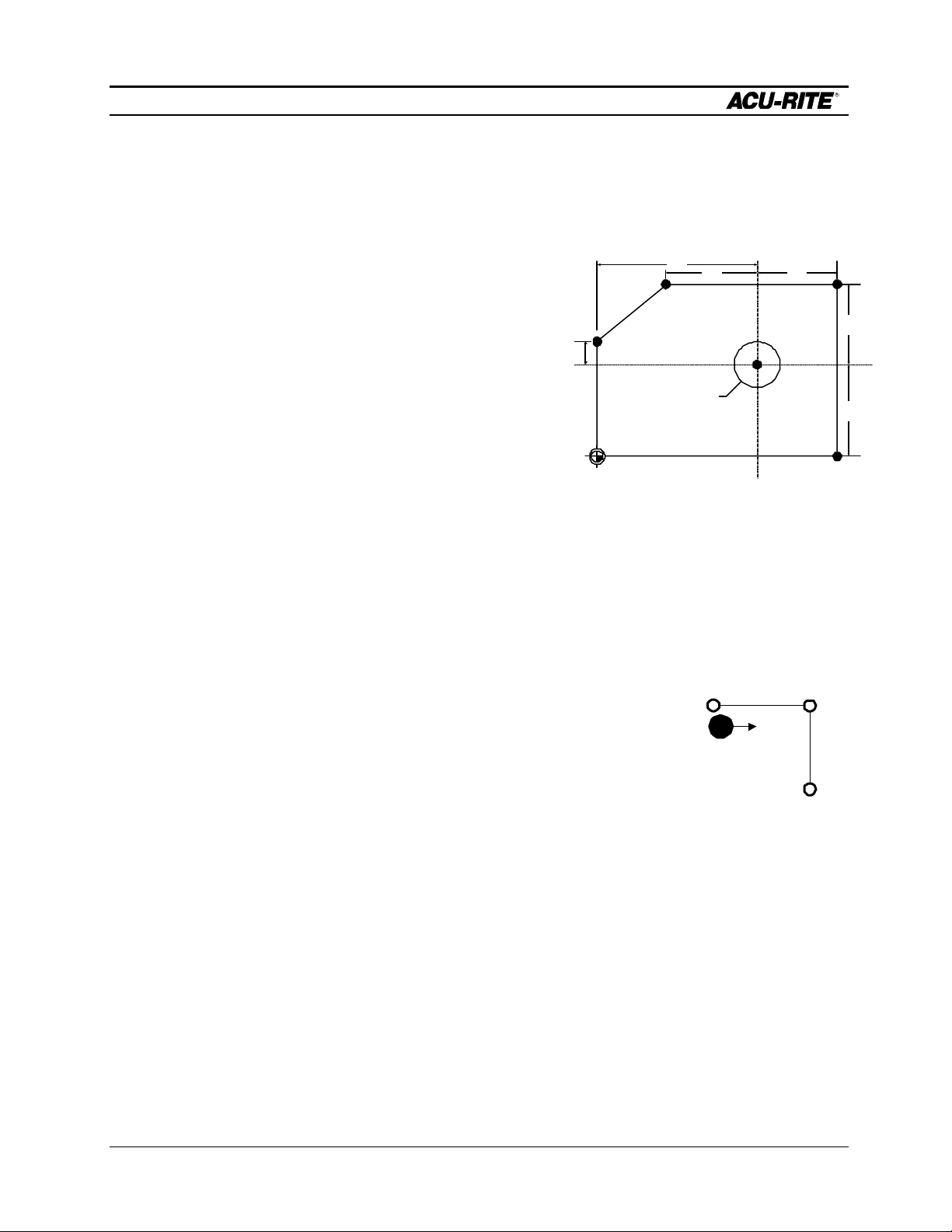
Although there is no clear “zero point” on this drawing, we’re going to use the center of the bolt hole
pattern as our datum. The advantages of using this point include:
• it is the center of the bolt hole pattern,
• it is the center of the large arc, making it easy to calculate the arc’s start and end points,
• the pocket is dimensioned from this point,
• the length of the straight side of the part is dimensioned from this point.
The workpiece can also be correctly programmed using another point (for example, the lower left
corner) as the datum.
When we are ready to run the program, we will actually set the datum.
Beginning The Program
Begin by pressing the program key.
PGM
Operation Manual Page 4-1
Page 56

DEMONSTRATION
MILLPWR
Selecting A Tool
A logical first step for most programs is to choose the tool that you want to start
with. Let’s use a ¼" FLAT END MILL.
Press the TOOL key.
TOOL
SERVO
OFF
FEED 0 100%
CURRENT PROGRAM
001 SET TOOL
1 OF 1
INCH MM
Enter .25 followed by the enter key.
SET TOOL 001
TOOL
INCH
TYPE
SCALE 1.0000TOOL:
INCH
TOOL
LIBRARY
. 2 5
ENTER
You can select a tool
from the Tool Library if
you like.
TOOL
0.250
INCH
TYPE
Press the TOOL TYPES softkey.
TOOL
TYPES
To FLAT END MILL
Arrow down to FLAT END MILL and press enter.
ENTER
USE
Press USE to complete the SET TOOL step.
Page 4-2 Operation Manual
Page 57

DEMONSTRATION
MILLPWR
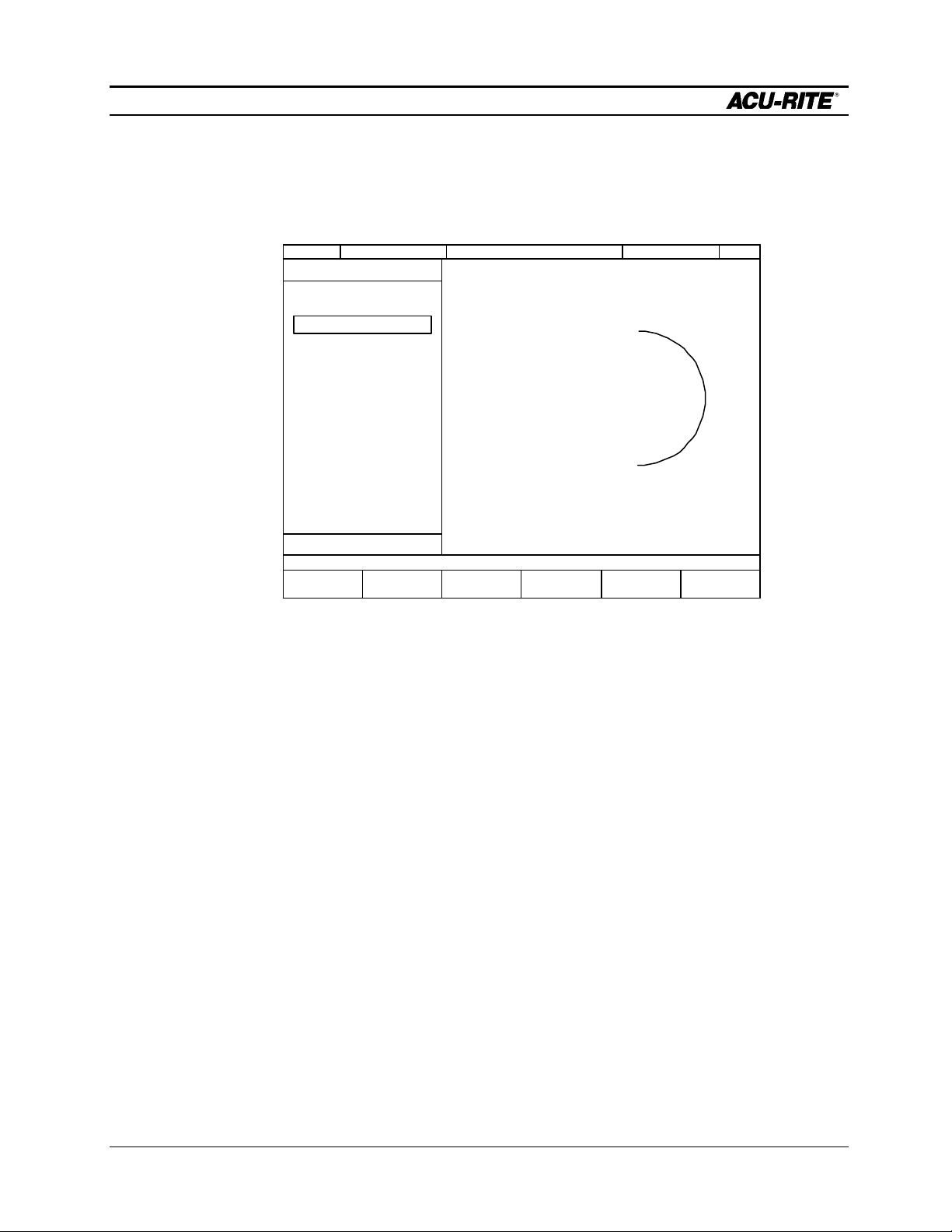
Milling the Workpiece Contour
This part could be started at several different places. We'll
start at the bottom of the semi-circle on the right end of the
workpiece, and we’ll cut in a counterclockwise (CCW)
direction.
Press the ARC key.
3.00
1.50R
ARC
SERVO
OFF
CURRENT PROGRAM
001 SET TOOL
002 MILL ARC
X
Enter the following dimensions:
FROM: X1 = 0
To enter a negative
number, use the +/“CHANGE SIGN”
key, not the
“MINUS” key. The
“MINUS” key will
subtract the number
you enter from the
number that’s
already there.
Y1 = -1.5
FEED 0 100%
2 OF 2
MILL ARC 002
FROM
X1 ABS
Y1 ABS
TO
X2 ABS
Y2 ABS
DEPTH
Z ABS
RADIUS
DIRECTION
CCW
TOOL
0.250 INCH
FL END ML TYPE
CENTER OFFSET
10FEED IPM
TEACH
POSITION
SCALE 1.0000TOOL:
INCH
MOREPOLAR
ENTER
0
+/-
1 5
.
ENTER
Operation Manual Page 4-3
Page 58

DEMONSTRATION
MILLPWR
TO: X2 = 0
Y2 = 1.5
DEPTH: Z = -.25
RADIUS: 1.5
DIRECTION: CCW
+/-
1 5
.
. 2 5
. 51
Since we are starting the arc on the bottom and moving around
to the top, we picked CCW for the direction.
The tool specifications will be filled in automatically based on the
previously selected tool.
ENTER
0
ENTER
ENTER
ENTER
CCW
Now move to OFFSET and select RIGHT or OUTSIDE from the softkey choices.
To OFFSET
RIGHT
Page 4-4 Operation Manual
Pick CCW from the
softkeys that appear
when you’re in the
Page 59

DEMONSTRATION
MILLPWR
Finally, move to FEED and enter the FEED RATE you
would like to use.
To FEED
MILLPWR has
been factory set
with a feed rate of
10 IPM.
1 0
ENTER
USE
SERVO
OFF
FEED 0 100%
CURRENT PROGRAM
001 SET TOOL
002 MILL ARC
END OF 2
SCALE 1.0000TOOL:
INCH
PROGRAM
FUNCTIONS
CLEAR
PROGRAM
EXPLODE
MORE
STEPS
RUN
OPTIONS
Operation Manual Page 4-5
Page 60

DEMONSTRATION
MILLPWR
Next, we will enter the 3" line which starts at the
top of the
arc and
goes left.
The FROM point of this line is
automatically set to the end of
the arc programmed before.
SERVO
OFF
FEED 0 100%
CURRENT PROGRAM
001 SET TOOL
002 MILL ARC
X
003 MILL LINE
MILL LINE 003
FROM
X1 ABS
TO
X2 ABS
Y2 ABS
DEPTH
TOOL
3 OF 3
0.000
1.500Y1 ABS
0.2500Z ABS
0.250 INCH
FL END ML TYPE
RIGHT OFFSET
10FEED IPM
TEACH
POSITION
SCALE 1.0000TOOL:
POLAR
INCH
3.00
1.50R
LINE
ENTER
+/-
3
Press the LINE key.
1 5.
ENTER
Enter the TO field: TO: X2 = -3.0 ABS
SERVO
OFF
Notice the marks
connecting steps
002 and 003. This
means that the line
FEED 0 100%
CURRENT PROGRAM
001 SET TOOL
002 MILL ARC
003 MILL LINE
SCALE 1.0000TOOL:
and arc form a
continuous contour,
and MILLPWR will
cut them without
stopping.
1.5
PROGRAM
FUNCTIONS
END OF 3
CLEAR
PROGRAM
EXPLODE
MORE
STEPS
Page 4-6 Operation Manual
RUN
OPTIONS
INCH
USE
Y
2
=
Page 61

DEMONSTRATION
MILLPWR
Operation Manual Page 4-7
Page 62

DEMONSTRATION
MILLPWR
Press the LINE key to add another line.The FROM
dimensions, DEPTH dimension, and TOOL specifications will
carry forward from the previous line.
.838
3.00
Press the LINE key.
Enter the following TO dimensions:
TO: X2 = -3.0 ABS
Notice that you
don’t have to use
the ENTER key
after the last
value – just
press USE.
Y2 = 0.838 ABS
SERVO
OFF
FEED 0 100%
CURRENT PROGRAM
001 SET TOOL
002 MILL ARC
003 MILL LINE
004 MILL LINE
LINE
ENTER
USE
+/-
3
8. 3 8
SCALE 1.0000TOOL:
INCH
END OF 4
PROGRAM
FUNCTIONS
CLEAR
PROGRAM
EXPLODE
MORE
STEPS
RUN
OPTIONS
Page 4-8 Operation Manual
Page 63

DEMONSTRATION
MILLPWR
Now we will program the two diagonal lines. Notice that in the xaxis the end of the first diagonal line is .750 from the beginning of
the line.
FROM (X1, Y1)
3.00
.750
This means we can use
incremental dimensioning.
.838
We say that “X2 is .750
incremental from X1.”
.75
TO (X2, Y2)
Press the LINE key.
LINE
In the TO point, enter
X2 = .750
7. 5
ABS
INC
Then press the ABS/INC key. ABS changes to INC, and
MILLPWR assumes that you want to use the X coordinate
of the FROM point, X1, as your incremental reference.
X2 = 0.750 INC X1
LINE
FROM
TO
Y2 ABS
-3.000X1 ABS
0.838Y1 ABS
0.750X2 INC XI
005
Now finish the TO point:
To Y2
Y2 = 0.000 ABS
0
USE
Operation Manual Page 4-9
Page 64

DEMONSTRATION
MILLPWR
Press the LINE key again for the second diagonal line:
LINE
X2 = -3.000 ABS
Y2 = -0.838 ABS
SERVO
OFF
CURRENT PROGRAM
001 SET TOOL
002 MILL ARC
003 MILL LINE
004 MILL LINE
005 MILL LINE
006 MILL LINE
FEED 0 100%
PROGRAM
FUNCTIONS
END OF 6
CLEAR
PROGRAM
EXPLODE
MORE
STEPS
+/-
ENTER
USE
+/-
3
8. 3 8
RUN
OPTIONS
INCH
SCALE 1.0000TOOL:
Page 4-10 Operation Manual
Page 65

DEMONSTRATION
MILLPWR
We can see that lines 005 and 006 should be
connected with an arc. We’ll go back and insert a
BLEND step between them. Using the up arrow key,
select the last step, 006 MILL LINE.
Press the BLEND key.
SERVO
OFF
FEED 0 100%
We could just as
easily have put
the BLEND step
in right after we
did LINE 005.
The BLEND step
would then show
CURRENT PROGRAM
001 SET TOOL
002 MILL ARC
003 MILL LINE
004 MILL LINE
005 MILL LINE
006 BLEND
X
007 MILL LINE
BLEND 006
STEPS
RADIUS
FEED RATE
up in the listing,
but it would not
show in the
graphics until we
put in the second
line.
6 OF 7
SCALE 1.0000TOOL:
INCH
5FROM
7TO
10
IPM
CLOSE
CONTOUR
To Step 006
BLEND
Enter a radius of 0.250.
SERVO
OFF
CURRENT PROGRAM
001 SET TOOL
002 MILL ARC
003 MILL LINE
004 MILL LINE
005 MILL LINE
006 BLEND
007 MILL LINE
FEED 0 100%
SCALE 1.0000TOOL:
INCH
2. 5
PROGRAM
FUNCTIONS
7 OF 7
CLEAR
PROGRAM
EXPLODE
MORE
STEPS
RUN
OPTIONS
USE
Operation Manual Page 4-11
Page 66

DEMONSTRATION
MILLPWR
Notice how the last two lines are now “blended” together
with a radius.
3.00
Press the down arrow key to move to the end of the program
to continue entering more steps.
Press the LINE key.
In the TO point enter:
X2 = -3.0 ABS
1.50R
To End of Program
LINE
ENTER
+/-
3
Y2 = -1.5 ABS
SERVO
OFF
CURRENT PROGRAM
001 SET TOOL
002 MILL ARC
003 MILL LINE
004 MILL LINE
005 MILL LINE
006 BLEND
007 MILL LINE
FEED 0 100%
PROGRAM
FUNCTIONS
7 OF 7
CLEAR
PROGRAM
EXPLODE
MORE
STEPS
USE
1 5.+/-
RUN
OPTIONS
INCH
SCALE 1.0000TOOL:
Page 4-12 Operation Manual
Page 67

DEMONSTRATION
MILLPWR
LINE
Press the LINE key. In the TO point enter:
Second line TO: X2 = 0 ABS
Y2 = -1.5 ABS
1 5.+/-
SERVO
OFF
Notice how the
marks to the right of
the step numbers
have changed to
indicate that the
contour is now
closed.
FEED 0 100%
CURRENT PROGRAM
001 SET TOOL
002 MILL ARC
003 MILL LINE
004 MILL LINE
005 MILL LINE
006 BLEND
007 MILL LINE
008 MILL LINE
009 MILL LINE
SCALE 1.0000TOOL:
INCH
ENTER
0
USE
END OF 9
PROGRAM
FUNCTIONS
CLEAR
PROGRAM
EXPLODE
MORE
STEPS
RUN
OPTIONS
Operation Manual Page 4-13
Page 68

DEMONSTRATION
MILLPWR
Programming the Bolt Circle
First, we want to change the tool to a drill. Press the
TOOL key and enter the data for a 0.250" drill.
TOOL
Select DRILL and press ENTER. Press USE to
complete the SET TOOL step.
Now, press the HOLES key to see a series of hole
pattern choices. Choose the BOLT CIRCLE softkey.
2. 5
BOLT CIRCLE
ENTER
TOOL
TYPES
To DRILL
ENTER
USE
HOLES
SERVO
OFF
FEED 0 100%
CURRENT PROGRAM
001 SET TOOL
002 MILL ARC
003 MILL LINE
004 MILL LINE
005 MILL LINE
006 BLEND
007 MILL LINE
008 MILL LINE
009 MILL LINE
010 SET TOOL
X
011 BOLT CIRCLE
BOLT CIRCLE 011
CENTER
X ABS
DEPTH
RADIUS
DIRECTION
HOLES
TOOL
0.00
0.00Y ABS
THRU
1.500
CCW
.2500 DIAMETER
DRILL TYPE
SCALE 1.0000TOOL:
INCH
11 OF 11
Page 4-14 Operation Manual
TEACH
POSITION
MOREPOLAR
Page 69

DEMONSTRATION
MILLPWR
The CENTER and DIRECTION are carried forward from the
previous arc. All we need to do is change the radius and enter
the number of holes.
CENTER: 0.0
0.0
DEPTH: THRU
RADIUS: 0.75
DIRECTION: CCW
The value of ”THRU” for the
depth is entered by a softkey. We
could choose not to program a
depth, since we can easily tell
when we drill through the part.
7. 5
To RADIUS
ENTER
HOLES: 5
When all dimensions are entered, press USE to view the
graphics screen.
SERVO
OFF
FEED 0 100%
CURRENT PROGRAM
001 SET TOOL
002 MILL ARC
003 MILL LINE
004 MILL LINE
005 MILL LINE
006 BLEND
007 MILL LINE
008 MILL LINE
009 MILL LINE
010 SET TOOL
011 BOLT CIRCLE
To HOLES
5
USE
SCALE 1.0000TOOL:
INCH
PROGRAM
FUNCTIONS
END OF 11
CLEAR
PROGRAM
EXPLODE
MORE
STEPS
RUN
OPTIONS
Operation Manual Page 4-15
Page 70

DEMONSTRATION
MILLPWR
Programming the Pocket
First we program the tool that we’ll use for the
pocket. Press TOOL and enter the data for a 0.125"
diameter flat end mill.
. 2 5
1
To FLAT END MILL
TOOL
TYPES
TOOL
ENTER
ENTER
USE
RECT
Press the RECT (rectangle) key, then select the softkey for POCKET.
SERVO
OFF
FEED 0 100%
CURRENT PROGRAM
001 SET TOOL
002 MILL ARC
003 MILL LINE
004 MILL LINE
005 MILL LINE
006 BLEND
007 MILL LINE
008 MILL LINE
009 MILL LINE
010 SET TOOL
011 BOLT CIRCLE
012 SET TOOL
013 RECTANGLE POCKET
X
13 OF 13
RECTANGLE POCKET
CENTER
X ABS
SIZE
DEPTH
CORNER BLEND RADIUS
DIRECTION
TOOL
0.0000
.2500
CCW
.1250
FL END ML
0.00
0.00Y ABS
10
IN X
IN Y
ABS
INCH
TYPE
IPM
TEACH
POSITION
011
POCKET
SCALE 1.0000TOOL:
INCH
MOREPOLAR
Page 4-16 Operation Manual
Page 71

DEMONSTRATION
MILLPWR
Enter the following dimensions for the rectangular pocket:
ENTER
5
ENTER
Some of these
dimensions are
already here so
we can down
arrow past them.
CENTER: X = -1.75
Y = 0.0
SIZE: X = 0.5
+/- 1 . 7
To Size
. 5
Y = 2.0
DEPTH: Z = -0.25
To Corner Radius
CORNER BLEND RADIUS : .125
. 1 52
DIRECTION: CCW
Press the USE key.
As with previous tool changes, the tool specifications will be automatically entered from the
SERVO
OFF
010 SET TOOL step.
FEED 0 100%
CURRENT PROGRAM
001 SET TOOL
002 MILL ARC
003 MILL LINE
004 MILL LINE
005 MILL LINE
006 BLEND
007 MILL LINE
008 MILL LINE
009 MILL LINE
010 SET TOOL
011 BOLT CIRCLE
012
SET TOOL
013
RECTANGLE POCKET
SCALE 1.0000TOOL:
INCH
ENTER
2
USE
END OF 13
PROGRAM
FUNCTIONS
CLEAR
PROGRAM
EXPLODE
MORE
STEPS
RUN
OPTIONS
Operation Manual Page 4-17
Page 72

DEMONSTRATION
GO
MILLPWR
Saving Your Program
The sample part is now completely programmed. Press the
softkey labeled PROGRAM FUNCTIONS.
PROGRAM
FUNCTIONS
Press the SAVE softkey.
Name your program by pressing the numeric keys or
by selecting the ALPHABET softkey, highlighting a
letter, then pressing the ENTER key. You may select up to eight characters,
mixing numbers and letters if you wish. After you’ve selected a name, press the
USE key to save the program. You will be warned if there's already a program
by that name.
Saving the program means it is stored and will not be lost if
there is a power interruption.
At a later time, you can recall the program by pressing the
PROGRAM FUNCTIONS and LOAD softkeys.
Testing Your Program
If you’re new to MILLPWR programming, you might want to
test your program before you run it. Press RUN OPTIONS , and
select both DRY RUN and GRAPHICS ONLY. Move to the start of the program
by pressing the 1 key followed by the ENTER
key, and press GO. Watch as MILLPWR
shows you how the part program
will be run.
If you are past the last
step, MILLPWR will
automatically go to step
1 when you press GO.
Key in program name.
OPTIONS
DRY RUN
GRAPHICS
SAVE
RUN
ONLY
1
ENTER
Under RUN OPTIONS , de-select the DRY RUN and GRAPHICS
ONLY options before proceeding.
RUN
OPTIONS
DRY RUN
GRAPHICS
ONLY
Page 4-18 Operation Manual
Page 73

DEMONSTRATION
MILLPWR
Operation Manual Page 4-19
Page 74

DEMONSTRATION
MILLPWR
Running the Program
The first step in running a new program is to set the datum point
on the workpiece. Remember that we chose the center of the
bolt circle as the datum.
• Mount the workpiece in a vise.
• Press DRO and use the MOVE TABLE function to position
the quill over the workpiece where you think the bolt circle
center might be.
• Release the MOVE TABLE function.
• Press the DATUM softkey.
• Press the X = 0 and Y = 0 keys to establish the current
tool center as the datum.
• Press USE to use this datum, and return to the program view
by pressing the PGM key.
MOVE
TABLE
Move the table to the
workpiece datum.
MOVE
TABLE
DATUM
X = 0 Y = 0
DRO
USE
PGM
We’ll do a dry run to see if the part will fit on the
workpiece.
RUN
OPTIONS
DRY RUN
• Press RUN OPTIONS and then DRY RUN.
• Now press GO, clear the tool and press GO again. The
MILLPWR will run each of the steps without stopping so
GO
GO
you can see the tool path.
Page 4-20 Operation Manual
Page 75

DEMONSTRATION
GO
MILLPWR
If the part falls entirely within the workpiece, you can now
actually cut the part.
• Press RUN OPTIONS , then deselect the DRY RUN softkey
to turn off dry run.
Now when you press the GO key, you can follow the
instructions MILLPWR gives you and make the part.
RUN
OPTIONS
DRY RUN
Operation Manual Page 4-21
Page 76

DEMONSTRATION
MILLPWR
Tool Changes
You may wish to
consider using a
POS step before
a tool step to
allow room for
changing the
tool.
Whenever MILLPWR encounters a SET
TOOL step, it shows you the DRO and
tells you which tool to load.
• Use the MOVE TABLE function to clear
the workpiece.
• Load the required tool.
• Using the move table function, position the tool over a surface
of known depth.
• Press the DATUM softkey.
• Touch the end of the tool to the
surface, key the known depth into the
Z axis.
Use move table function to
If the surface is
at 0, use the Z =
0 key.
MOVE
TABLE
Load tool.
position the tool.
MOVE
TABLE
DATUM
Touch end of
tool to
surface.
Key in depth
of Z axis.
Press the USE key.
USE
Raise tool.
• Raise the tool and press GO to resume the program.
• Follow the instructions on the MILLPWR screen.
GO
Clearing the Program
Select PROGRAM FUNCTIONS again.
PROGRAM
FUNCTIONS
Select the softkey marked CLEAR to clear the program
from the screen.
CLEAR
Page 4-22 Operation Manual
Page 77

DEMONSTRATION
MILLPWR
Answer YES and the screen will be cleared for another program.
YES
Operation Manual Page 4-23
Page 78

PROGRAM STEPS
SET TOOL
001
INCH
POSITION/DRILL
001
X
ABS
MILLPWR
PROGRAM STEPS
Simple Milling & Drilling
Set Tool
TOOL
Tool Types
and the Tool
Library are
opened with
softkeys.
This step causes MILLPWR to suspend the program and ask
you to change the cutting tool.
You have several options for filling in this step:
TOOL
TYPE
• Leave it blank; just press USE to insert an “empty” tool
step in the program. When you run the program,
MILLPWR will ask you what tool diameter to use.
• Type in a DIAMETER.
• Type in the DIAMETER and select a TOOL TYPE. Now
MILLPWR will let you know what kind of tool you had in
mind when you wrote the program.
• Select a tool from the Tool Library.
Any time you are entering the tool diameter, a softkey will let you change between
inches and mm.
Position/Drill
This operation is used to move the table at high speed to a
POS
specified position and drill to a programmed depth.
POINT is the X and Y position you want the tool to move to.
DEPTH is normally THRU for holes, but you can set it to a
specific depth.
The TOOL information is from the most recent SET TOOL step;
POINT
Y ABS
DEPTH
Z ABS
0.0000
TOOL
INCH
TYPE
you can’t change it here.
Operation Manual Page 5-1
Page 79

PROGRAM STEPS
MILL LINE
001
MILL ARC
001
0.0000
MILLPWR
Mill Line
LINE
ARC
This function moves rapidly to the starting point and mills a
line to the end point at the programmed feed rate.
FROM and TO are the beginning and ending points of the line.
TOOL OFFSET is set with softkeys LEFT, CENTER, or RIGHT.
FEED must be programmed or it will default to the last
feedrate used or from the value entered in setup.
Mill Arc
This operation performs an arc cut at a given depth and feed
rate.
The usual arc definition uses the
FROM and TO points, the RADIUS
of the arc and the DIRECTION of
the arc. The direction of the arc is
CCW
FROM
R
either clockwise (CW) or
counter-clockwise (CCW).
TO
In some cases, it may be necessary to enter the CENTER, a
3RD POINT, or a SWEEP ANGLE to define the arc. Press the
MORE softkey for additional input fields.
CW
FROM
X1 ABS
Y1 ABS
TO
X2 ABS
Y2 ABS
DEPTH
Z
TOOL
ABS
INCH
TYPE
CENTER OFFSET
10FEED IPM
FROM
X1 ABS
Y1 ABS
TO
X2 ABS
Y2 ABS
DEPTH
Z ABS
R
RADIUS
DIRECTION
CCW
TOOL
INCH
TYPE
CENTER OFFSET
10FEED IPM
CENTER
X ABS
Y ABS
3RD POINT
X3 ABS
Y3 ABS
SWEEP ANGLE
TO
TO
SWEEP
ANGLE
FROM
3RD
POINT
FROM
Page 5-2 Operation Manual
Page 80

PROGRAM STEPS
6
MILLPWR
Blend
BLEND
A blend is a circular fillet (connecting radius) which
connects two lines, two arcs, or a line and an arc. Just
give the RADIUS of the blend, and MILLPWR will
calculate the exact tangent points for you.
BLEND 001
STEPS
FROM
TO
RADIUS
The STEPS are filled in automatically; the FROM step is
the one before the blend, and the TO step is the one after
the blend. You can program the blend right after the
FROM step, before you have entered the TO step. Or,
you can enter the lines and arcs first, then go back and
insert the blend.
The two lines or arcs which are being blended do not
need to touch, or they can overlap. As long as the blend
radius will fit somewhere, it will work.
LINES 1 AND 3 TOUCH
LINE 1
001 LINE 0,6 TO 8,6
002 BLEND R=2
003 LINE 8,6 TO 8,0
8
LINE 3
LINES 1 AND 3 OVERLAP LINES 1 AND 3 DO NOT TOUCH
LINE 1 LINE 1
001 LINE 0,6 TO 8,6
6
002 BLEND R=2
003 LINE 8,7 TO 8,0
LINE 3
8
FEED RATE
001 LINE 0,6 TO 8,6
6
002 BLEND R=2
003 LINE 8,2 TO 8,0
10 IPM
LINE 3
8
If you have a closed contour, like a triangle, and you want to blend the last line to the
first line, put a blend step immediately after the last step in the contour and, while in the
RADIUS field, press the CLOSE CONTOUR softkey. The TO step number will be set to
the first step in the contour.
LINE 5
LINE 3
001 LINE
002 BLEND 001 TO 003
003 LINE
004 BLEND 003 TO 005
005 LINE
LINE 1
LINE 5
LINE 3
001 LINE
002 BLEND 001 TO 003
003 LINE
004 BLEND 003 TO 005
005 LINE
006 BLEND 005 TO 001
LINE 1
Operation Manual Page 5-3
Page 81

PROGRAM STEPS
MILLPWR
Rectangular Milling Functions
RECT
MILLPWR will arc
on and arc off
the last cut.
Z DEPTH
MILLPWR has several “canned cycles” to let you program pockets, frames, and slots
with a single step. There is also a step to let you face off a workpiece.
Pressing the RECT key on the front panel will display these softkeys.
POCKET FRAME FACE SLOT
Pocket
A pocket is defined by its CENTER point and its SIZE. You
can specify a CORNER RADIUS. You can also specify the
DIRECTION, which will determine whether you are climb
milling or conventional milling.
The tool must be able to fit into the pocket or the MILLPWR
wi ll not run the step.
The MORE softkey brings up the TILT ANGLE and FINISH CUT
fields.
Y
SIZE IN
SIZE IN
X
FINISH
ALLOWANCE
If you enter a finish
feed rate of 0,
MILLPWR will not
perform a finish cut.
RECTANGLE POCKET 001
CENTER
X ABS
Y ABS
SIZE
DEPTH
CORNER BLEND RADIUS
DIRECTION
TOOL
TILT ANGLE
0° 00' 00"
FINISH
FEED IPM
DIR
STEPOVR %
0.0000Z ABS
0.0000
CCW
10FEED IPM
0.0000 CUT
80
IN X
IN Y
INCH
TYPE
0
ccw
When tilted, the
pocket is rotated
about its center
TILT ANGLE
+X
point.
Page 5-4 Operation Manual
Page 82

PROGRAM STEPS
MILLPWR
Rectangular Frame
RECTANGLE FRAME 001
CENTER
X ABS
Y ABS
SIZE
DEPTH
CORNER BLEND RADIUS
DIRECTION
TOOL
CENTER OFFSET
TILT ANGLE
FINISH
FEED
DIR
0.0000Z ABS
0.0000
CCW
10FEED IPM
0° 00' 00"
0.0000 CUT
0
IN X
IN Y
INCH
TYPE
IPM
ccw
Of course, it’s
much easier
to use the
INSIDE and
OUTSIDE
softkeys!
A frame step takes one cut in a rectangular shape. The frame is
defined by its CENTER and SIZE. As with a pocket, you can
have rounded corners, and the DIRECTION determines the
milling type.
You decide if it’s an inside or an outside frame with the tool
offset: LEFT with a CCW direction or RIGHT with CW will give
you an inside frame cut; RIGHT with a CCW direction or LEFT
with CW will give an outside frame cut.
The MORE key shows you the TILT ANGLE and FINISH CUT
fields.
Z DEPTH
SIZE IN
Y
SIZE IN X
OUTSIDE FRAME
FINISH
ALLOWANCE
Z DEPTH
SIZE
IN Y
SIZE IN
X
INSIDE FRAME
FINISH
ALLOWANCE
Operation Manual Page 5-5
Page 83

PROGRAM STEPS
MILLPWR
Face
This step provides a quick way to face off a workpiece. Enter
the CENTER location and the SIZE of the area to be faced.
MILLPWR will start at the lower left of the area and zigzag
upwards.
The MORE softkey brings up fields to let you TILT the face
rectangle, and to change the tool STEPOVER.
SIZE IN X
FACE 001
CENTER
X ABS
Y ABS
SIZE
DEPTH
TOOL
IN X
IN Y
0.0000Z ABS
INCH
TYPE
10FEED IPM
SIZE IN Y
STEPOVER
SERPENTINE PATH
(NO TOOL OFFSET)
TILT ANGLE
0° 00' 00"
FINISH
STEPOVR %
Page 5-6 Operation Manual
Page 84

PROGRAM STEPS
MILLPWR
Slot
For a slot, enter the CENTER of each arc and the SLOT
WIDTH. You can enter the SLOT LENGTH and ANGLE instead
of the 2ND ARC CENTER.
The MORE softkey displays fields which let you specify the
ANGLE of the slot (it rotates about the FIRST ARC CENTER)
and enter a FINISH CUT .
WIDTH
LENGTH
ANGLE
1ST ARC CENTER
EITHER END
2ND ARC CENTER
SLOT 001
FIRST ARC CENTER
X1 ABS
Y1 ABS
SECOND ARC CENTER
X2 ABS
Y2 ABS
DEPTH
DIRECTION
CCW
SLOT WIDTH
TOOL
SLOT LENGTH
ANGLE
FINISH
FEED
DIR
STEPOVR %
0.0000Z ABS
INCH
TYPE
10FEED IPM
0.0000 CUT
0
IPM
ccw
80
Operation Manual Page 5-7
Page 85

PROGRAM STEPS
MILLPWR
Circular Milling Functions
CIRCLE
MILLPWR has several “canned cycles” to let you program pockets, frames, and rings
with a single step.
Pressing the CIRCLE key on the front panel will display these softkeys.
POCKET FRAME RING
Circular Pocket
Enter the CENTER and RADIUS of the pocket. The
DIRECTION will determine whether you are climb or
conventional milling.
The MORE key brings up the FINISH CUT option.
CIRCLE POCKET 001
CENTER
X ABS
Y ABS
DEPTH
RADIUS
0.0000Z ABS
Z DEPTH
STEPOVER
RAD
FINISH
ALLOWANCE
DIRECTION
CCW
TOOL
INCH
TYPE
10FEED IPM
FINISH
STEPOVR %
FEED
DIR
0.0000 CUT
0
IPM
ccw
80
Page 5-8 Operation Manual
Page 86

PROGRAM STEPS
MILLPWR
Circular Frame
The INSIDE
and OUTSIDE
softkeys can
help you with
the Tool Offset.
Enter the frame’s CENTER and RADIUS. The DIRECTION,
coupled with the TOOL OFFSET, will determine whether you
are climb or conventional milling, and whether you are cutting
an inside or outside frame.
The MORE softkey brings up fields to let you enter a FINISH
cut.
FINISH
ALLOWANCE
RAD
Z DEPTH
OFFSET = INSIDE
FINISH
ALLOWANCE
CIRCLE FRAME 001
CENTER
X ABS
Y ABS
DEPTH
RADIUS
DIRECTION
TOOL
FINISH
DIR
0.0000Z ABS
CCW
CENTER
10FEED IPM
0.0000 CUT
0FEED
INCH
TYPE
OFFSET
IPM
ccw
Z DEPTH
RAD
OFFSET = OUTSIDE
Operation Manual Page 5-9
Page 87

PROGRAM STEPS
MILLPWR
Ring
A ring is actually a circular pocket with a circular island in the
center.
Enter the CENTER position, the radius of the pocket
(OUTSIDE RADIUS), and the radius of the island (INSIDE
RADIUS).
The DIRECTION of cut on the inside radius will determine
whether you are climb milling or conventional milling.
MILLPWR will reverse the tool movement direction on the
outside radius so the milling direction stays the same.
The MORE softkey brings up the FINISH CUT entry field.
RING 001
CENTER
X ABS
Y ABS
DEPTH
RADIUS
DIRECTION
TOOL
0.0000Z ABS
OUTSIDE
INSIDE
CCW
INCH
TYPE
10FEED IPM
Z DEPTH
RAD 1
RAD 2
FINISH
ALLOWANCE
FINISH
FEED
DIR
STEPOVR %80
0.0000 CUT
0
IPM
CCW
Page 5-10 Operation Manual
Page 88

PROGRAM STEPS
MILLPWR
Hole Patterns
HOLES
MILLPWR has several “canned cycles” to let you program patterns of holes.
Pressing the HOLES key on the front panel will display these softkeys.
ROW FRAME ARRAY BOLT CIRCLE
Row of Holes
The FROM point is the center of the first hole, and the TO
point is the center of the last hole. Enter the number of holes in
the HOLES field.
Instead of the TO point, you can enter the HOLE SPACING
and ANGLE.
ROW OF HOLES 001
FROM
X1 ABS
Y1 ABS
TO
X2 ABS
Y2 ABS
DEPTH
THRUZ ABS
HOLES
TOOL
HOLE SPACING
ANGLE
INCH
TYPE
BETWEEN
ANGLE
Operation Manual Page 5-11
Page 89

PROGRAM STEPS
MILLPWR
Hole Frame and Hole Array
The frame and the array hole patterns need the same
information. Arrays have holes in the middle of the rectangular
pattern, while frames have holes only on the outside edge of
the rectangle.
Enter the rectangle’s CENTER and SIZE, and the number of
HOLES in each direction.
The MORE softkey brings up fields to let you TILT the frame or
to enter the hole-to-hole SPACING.
HOLE FRAME 001
CENTER
X ABS
Y ABS
SIZE
DEPTH
HOLES
X
Y
TOOL
THRUZ ABS
IN X
IN Y
INCH
TYPE
SIZE IN Y
FRAME ARRAY
SIZE IN X
SIZE IN Y
CENTER
SIZE IN X
CENTER
HOLE SPACING
X BETWEEN
Y BETWEEN
TILT ANGLE
0° 00' 00"
Page 5-12 Operation Manual
Page 90

PROGRAM STEPS
MILLPWR
Bolt Circle
Enter the CENTER and the RADIUS of the bolt circle, and the
number of HOLES you want.
The MORE softkey brings up the START ANGLE and END
ANGLE entry fields, which let you do partial circles. The
number of holes you entered will be spaced evenly between
the angles.
The DIRECTION field is useful if you have a clamp or fixture
that you need to avoid.
END
ANGLE
BOLT CIRCLE 001
CENTER
X ABS
Y ABS
DEPTH
THRUZ ABS
RADIUS
DIRECTION
HOLES
TOOL
START ANGLE
CCW
INCH
TYPE
START
ANGLE
END ANGLE
+X
Operation Manual Page 5-13
Page 91

PROGRAM STEPS
MILLPWR
More Steps
MORE
STEPS
Additional steps are available that extend the capabilities of your MILLPWR. Select the
MORE STEPS softkey to see a menu of the following extended functions:
CUSTOM
POCKET
REPEAT ROTATE MIRROR ENGRAVE
REFERENCE
POINT
Repeat
Using this step you can repeat whole parts, or sections of parts,
horizontally, vertically, or both.
Enter the STEP RANGE (the numbers of the first and last steps)
that you want to repeat and the OFFSET, in either X or Y, or
both directions. Then enter the number of REPEATS you want
REPEAT 005
STEP RANGE
FIRST
LAST
OFFSET
X
Y
REPEAT
MORE
in addition to the original. The offset is the distance between
repeats.
Example:
001 MILL LINE
002 MILL LINE
003 MILL LINE
004 POSITION/DRILL
To repeat the above program once, 6 inches to the right, fill in the REPEAT form like
this:
REPEAT 005
STEP RANGE
OFFSET
Y
REPEAT
6.000X
001FIRST
004LAST
1 MORE
ORIGINAL REPEAT
6
Page 5-14 Operation Manual
Page 92

PROGRAM STEPS
MILLPWR
Rotate
Just as you can repeat sections of a program, you can also
rotate sections.
Enter the CENTER of rotation and the ANGLE of rotation.
Example:
ROTATE 005
STEP RANGE
FIRST
LAST
CENTER
X ABS
Y
ANGLE
ABS
001 MILL LINE
002 MILL LINE
003 MILL LINE
004 POSITION/DRILL
To rotate the part twice at 30° each, fill in the ROTATE
form like this:
ROTATE 005
STEP RANGE
CENTER
ANGLE
REPEAT
001FIRST
004LAST
ABS
1.000X
ABS
0.000Y
30
MORE
2
30°
30°
CENTER
REPEAT
ORIGINAL:
STEPS 001
THRU 004
MORE
1.000
Operation Manual Page 5-15
Page 93

PROGRAM STEPS
MILLPWR
Mirror
You can make a mirror image of any section of your
program using this step. Enter the RANGE of steps you want
to mirror, and the end points of the “mirror line,” called the
axis of reflection. The axis does not have to be vertical or
horizontal; you can use any line.
Example:
001 MILL LINE
002 MILL LINE
003 MILL LINE
004 POSITION/DRILL
To make a “left handed” part 2 inches away, put a
vertical axis 1 inch to the left of the original part.
MIRROR 005
STEP RANGE
1ST AXIS POINT
2ND AXIS POINT
001FIRST
004LAST
ABS
-1.000X
ABS
0.000Y
-1.000X ABS
1.000Y ABS
AXIS OF
REFLECTION
MIRROR 005
STEP RANGE
FIRST
LAST
1ST AXIS POINT
X1 ABS
Y1
2ND AXIS POINT
X2 ABS
Y2 ABS
ABS
LEFT HAND PART
1.0
2.0
ORIGINAL
STEPS 001 THRU 004
The axis line
doesn’t have to be
very long--this one
is only 1”.
Page 5-16 Operation Manual
Page 94

PROGRAM STEPS
MILLPWR
Custom Pocket
CUSTOM POCKET 005
STEP RANGE
ENTRY POINT
X
Y
RATE
FINISH
DIRECTION
STEPOVR %
2FIRST
4LAST
ABS
ABS
10 IPMFEED
0.0000 CUT
0FEED IPM
ccw
50
MILLPWR
will arc on
and arc off
the last cut.
You can create a pocket from any closed contour. A
closed contour is any shape made of lines, arcs, and/or
blends, where the last step ends at the start point of the
first step. MILLPWR will indicate a closed contour with
double lines to the right of the applicable steps in the
program list.
The CUSTOM POCKET step must be placed immediately
following the last step in the closed contour.
In the CUSTOM POCKET step, the STEP RANGE is filled in
automatically. You need to fill in the ENTRY POINT , which
is the plunge point for the tool. MILLPWR will mill at the
feed rate from the ENTRY POINT to the start of the first
step in the contour.
Set the FEED RATE if you want to override what is in each of the contour steps.
The FINISH CUT will be done after the inside of the pocket has been cleared out.
The direction of cut is determined by the order in which you programmed the elements
of the contour.
Operation Manual Page 5-17
Page 95

PROGRAM STEPS
MILLPWR
Engrave
You can engrave part numbers and other text into a part using this feature. The
ENGRAVE feature has two parts. First, specify the characteristics of the text, such as
where it goes and how large it is. Then you need to select the actual text characters
(alpha or numeric) that you want to engrave.
The text that you specify will occupy a rectangular area called a text block.
Use
“mirrored” if
you’re making
a mold.
EXAMPLE:
AMERICAN WIDGET
PART NUMBER 4562-001033VJ
MADE IN USA
To get the ENGRAVE TEXT step, press the MORE STEPS softkey, then the ENGRAVE
softkey.
ENGRAVE TEXT 001
First, enter the location on the part for the UPPER LEFT
CORNER of the text block, then the CHARACTER HEIGHT .
If you enter a TILT ANGLE, the entire text block will be
rotated around the upper left corner.
The way the text letters and numbers look is called style.
STYLE has two parts: FONT and MODIFIER.
You may select the FONT from the list available under the
ENGRAVER FONTS softkey. The font determines the shapes
of the characters. In the MILLPWR STICK font, characters
UPPER LEFT CORNER
X ABS
Y ABS
CHARACTER HEIGHT
TILT ANGLE
0° 00' 00"
DEPTH
STYLE
TOOL
FEED
0.000Z ABS
STICK FONT
NORMAL MODIFIER
INCH
TYPE
10
IPM
are formed with straight lines. In the SIMPLE font, both lines
and arcs are used to form characters. Some fonts have more characters to choose from
than others.
The MODIFIER field lets you select between normal and mirrored text using softkeys.
Page 5-18 Operation Manual
Page 96

PROGRAM STEPS
MILLPWR
The second part is to enter the text characters. Press the EDIT TEXT softkey to see the
ENGRAVE TEXT EDITOR.
This area will hold
the contents of the
This is the “insertion
point”, where the next
character will go.
text block.
The screen is divided into the TEXT BLOCK area and the CHARACTERS area. The TEXT
BLOCK area is where you see the text that you will engrave. The CHARACTERS area
contains all the different characters that are available in the font you have selected.
With the CHARACTERS softkey pressed, use the arrow keys to select the character you
want, then press ENTER. That character is put into the TEXT BLOCK area at the
insertion point. You can leave a space between characters by using a blank “character”.
With the TEXT BLOCK softkey pressed, you can use the arrow keys to move the
insertion point. This is how you place text on more than one line.
If you place the insertion point over an existing character, the DEL key will erase it.
The DELETE LINE softkey will erase the entire line of text that the insertion point is in,
and move all following text lines up. The INSERT LINE softkey will insert a blank text
line, moving existing text lines down. The CLEAR ALL softkey will erase all the text in
the TEXT BLOCK area.
When you have the text block set up the way you want, release the EDIT TEXT softkey
(or press USE) to get back to the ENGRAVE step. MILLPWR will draw the text block
for you to inspect. Press the EDIT TEXT softkey if you want to make changes, or press
USE to enter the step into your program.
Operation Manual Page 5-19
Page 97

PROGRAM STEPS
MILLPWR
Explode
Any repetitive type of step causes MILLPWR to create copies of one or more
Strictly speaking,
EXPLODE is not
a step, but it can
create steps.
simpler steps. For example, the ROTATE step below creates 2 copies of the
contour-with -hole shape, yet it only takes one step. Similarly, a single BOLT
CIRCLE step causes MILLPWR to drill several holes.
002 MILL LINE
003 MILL LINE
004 MILL LINE
005 POSITION / DRILL
006 ROTATE (002 - 005)
Repetitive type steps include REPEAT, ROTATE, MIRROR, ROW OF HOLES, HOLE
FRAME, HOLE ARRAY, and BOLT CIRCLE.
The EXPLODE function will take one of these repetitive type steps and replace it with
the individual steps. This is useful when you need to change or eliminate one of the
individual steps.
For example, to program an eight-hole bolt circle without the third hole:
1. Program the eight-hole bolt circle.
2. Highlight the BOLT CIRCLE step.
3. Press EXPLODE. The BOLT CIRCLE step is removed and eight POSITION / DRILL
steps are inserted in its place.
4. Move to the third hole and press the DEL key.
002 BOLT CIRCLE 002 POSITION / DRILL
EXPLODE STEP 002
TO GET 8 POS /
DRILL STEPS.
HIGHLIGHT THE
THIRD HOLE AND
PRESS THE
DEL
KEY.
003 POSITION / DRILL
004 POSITION / DRILL
005 POSITION / DRILL
006 POSITION / DRILL
007 POSITION / DRILL
008 POSITION / DRILL
009 POSITION / DRILL
002 POSITION / DRILL
003 POSITION / DRILL
004 POSITION / DRILL
005 POSITION / DRILL
006 POSITION / DRILL
007 POSITION / DRILL
008 POSITION / DRILL
Page 5-20 Operation Manual
Page 98

CALCULATOR
MILLPWR
CALCULATOR
Four Function Arithmetic
The four arithmetic keys,
+ - X /
numeric entry field, such as X, Y, CENTER, or RADIUS. Just use these keys as you
would any calculator.
KEY
RESULT
2 2 + 5 7
The keys will act on a number that is already in the field. For example, if you move to a
radius field which already has a value of 3.125, and you want to double it, just press:
ENTER
2
X
to get 6.250.
When you have more than one calculation in a field, the calculator will perform
multiplication and division before it does addition and subtraction. This means that you
can enter 3 + 1 / 8 to get three and one-eighth (the 1 / 8 is done before the 3 is added).
Trig and Math Functions
+2 5
, are available when you are in any
ENTER
When you're entering data for a milling or positioning function, part dimensions will not
always be given. In some cases, it will be possible to calculate the dimensions using the
trig calculator. If the unknown coordinate can be expressed as a trig function, a square
root or the square of a number, MILLPWR can calculate it.
While in a point entry field such as X, Y, or CENTER, press the CALC key. The following
trig function softkeys are shown.
SHIFT
ARC COS ARC SIN ARC TAN SQR
SQR ROOTTANSINCOS (
)
Most of the calculator softkeys are divided in half. At first, the top half is “active”, while
the bottom half is “inactive”. Select the SHIFT softkey and the bottom half of the
calculator options becomes active:
Operation Manual Page 6-1
Page 99

CALCULATOR
MILLPWR
Notice that you
can press the
CALC key first,
and just stay in
the calculator.
SHIFT
SHIFT
TANSINCOS (
ARC TANARC SINARC COS )
SQR ROOT
SQR
X
Typically, a result is calculated by entering a number and then selecting the appropriate
math function. For example, to enter a RADIUS whose value is the square root of 2,
press the 2 key, the CALC key and then select the SQR ROOT softkey. A value of
1.4142 (the square root of 2) will be displayed.
2
RADIUS
2
CALC
RADIUS
Trig functions are calculated by entering the angle first and then the appropriate trig
function. For example, enter 30, then select the SIN softkey. A value of 0.5000 (SIN
30°) will be displayed.
CALC
3
0
SQR ROOT
SQR
1.4142
SIN
ARC SIN
RADIUS
30
RADIUS
0.5000
Typically, a trig value must be multiplied by another number to calculate an actual
dimension. In the example above, assume the 0.5000 must be multiplied by the length of
a triangle's hypotenuse, say 4, to calculate the side opposite the 30° angle.
X
4
ENTER
0.5000 0.5000 X 2.0004
Page 6-2 Operation Manual
Page 100

CALCULATOR
MILLPWR
The parentheses softkeys can be used to group certain calculations within an arithmetic
statement. For example,
2 + 1 / 16 gives two and one-sixteenth, but
(2 + 1) / 16 gives three-sixteenths.
The parentheses are not always displayed during the key stroke sequence, but they are
remembered by the MILLPWR as it calculates the correct answer.
Operation Manual Page 6-3
 Loading...