

Page 1
ENC 250™ SINGLE SECTION
REFERENCE MANUAL
Acu-Rite Companies Inc.
Page 2

Page 3
ENC 250™ SINGLE SECTION
Table of Contents
Page
Introduction..............................................................................2
Mounting Preparation .............................................................3
Mounting Information ............................................................. 4
Encoder Dimensions ................................................................5
Mounting Requirements..........................................................6
Installation Procedure .............................................................7
Tape Tensioning.....................................................................10
Electrical Shielding................................................................12
Troubleshooting .....................................................................13
Mechanical Specifications ..................................................... 14
Output Signals and Pin-Outs................................................15
Electrical Specifications ........................................................16
The ACU-RITE Warranty ....................................................17
Tool Requirements .................................................................18
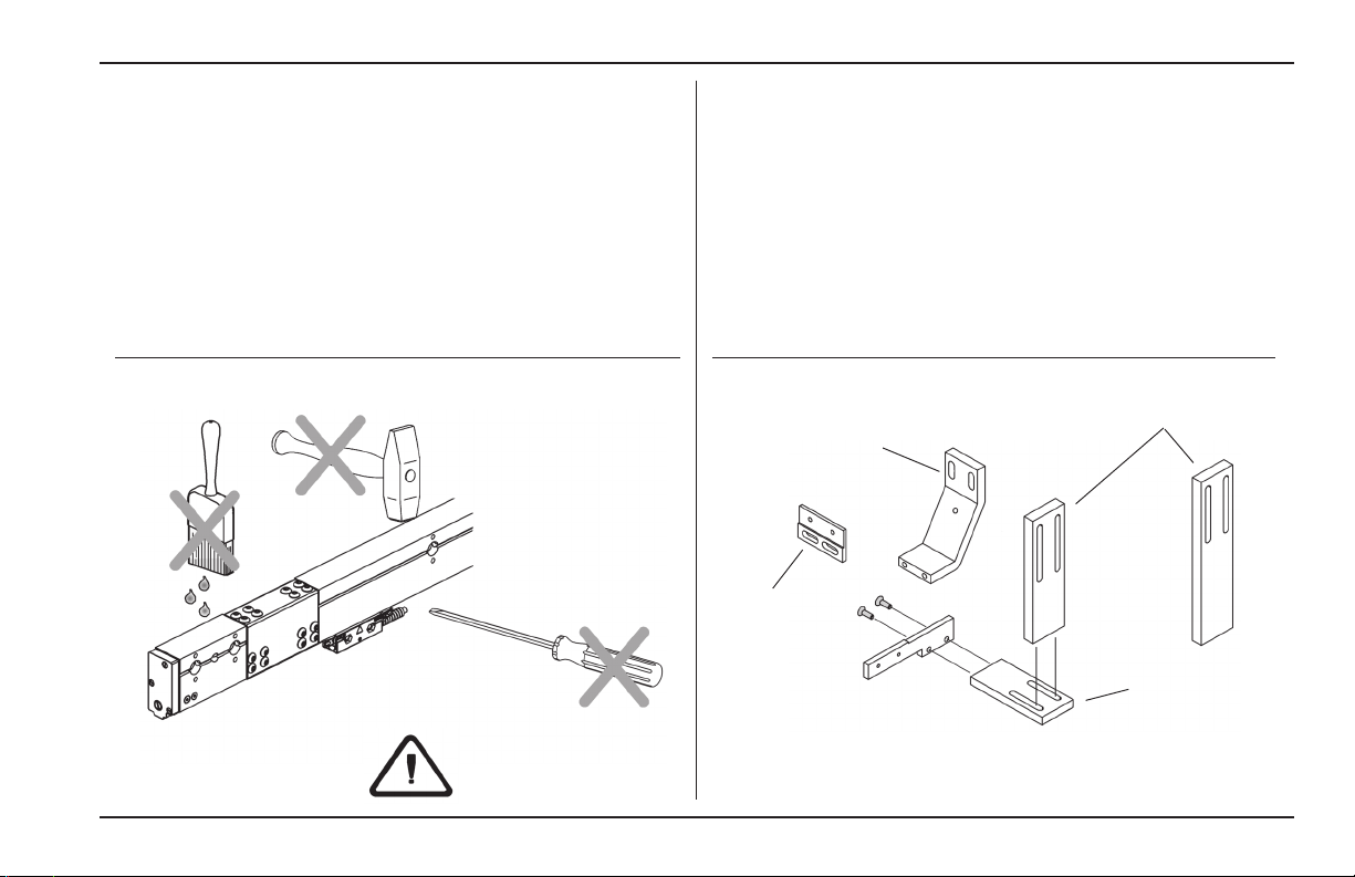
Brackets ...
Off set side
mount bracket
Reading head
mounting plate
Universal side mounting bracket
(Available in different lengths)
Combination
reading head bracket
w/extension
• Installation brackets are available.
• Your authorized distributor can assist you in selecting
brackets for your installation.
1
Acu-Rite Companies Inc.
Page
Page 4
Introduction / Supplied Items
ENC 250™ SINGLE SECTION
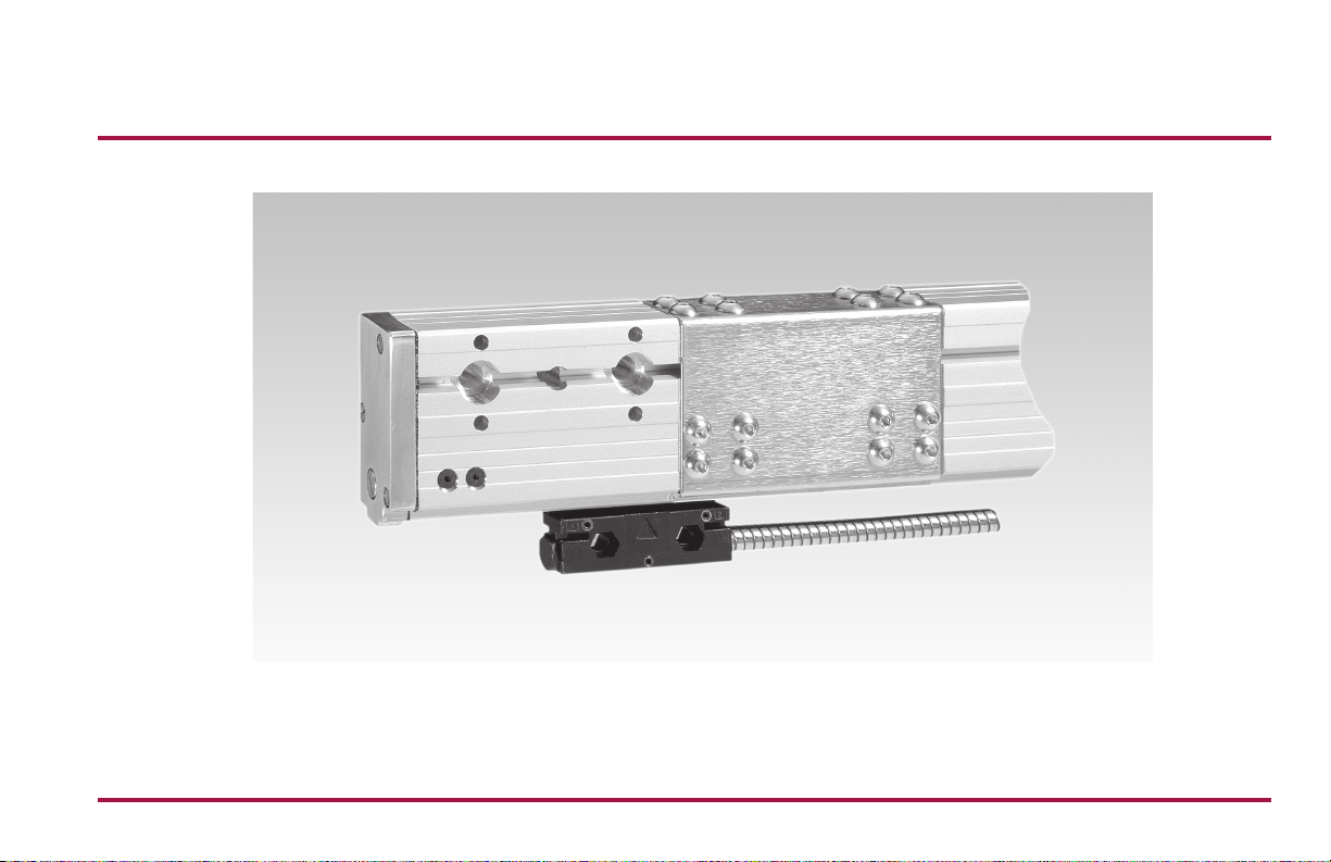
The ENC 250 linear encoder provides the accuracy and
reliability of an Acu-Rite Companies Inc. measuring system
with digital output. Features and options include:
• Resolution of [.0002in.] 5µm
• Accuracy grade of +/-15µm/M
• [2 ft.] .61m armor cable and extension cables up to a maximum of
[75 ft.] 22.86m for a VRO; [35 ft.] 10.67m for a DRO
• Mounting hardware
• Brackets and accessories
Contact your Authorized Distributor for a complete list of
other products and accessories.
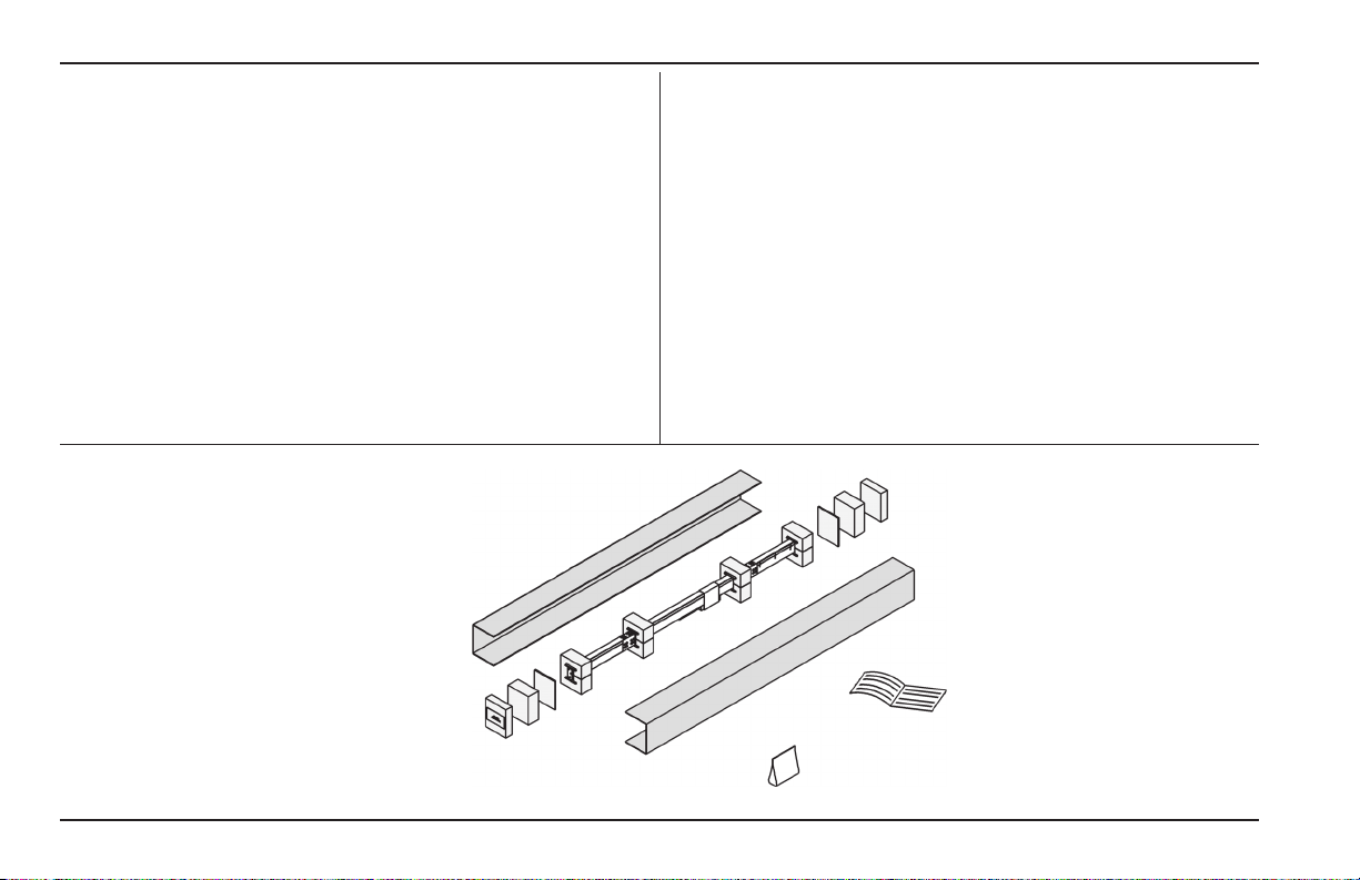
Contents ...
For future ordering information or warranty service, record
the linear encoder catalog number located on the scale
assembly tag, and the serial number from the reading head
tag.
Catalog No. Serial No.
Axis: _______________ __________________
Tape tension value: ___________________________________
Date of purchase: ____________________________________
Distributor: ____________________________________
Address: ____________________________________
Telephone: ____________________________________
A
C
A • ENC 250 Linear Encoder
B • Encoder mounting hardware
C • Reference Manual
Acu-Rite Companies Inc.
B
2
Page 5
ENC 250™ SINGLE SECTION
Mounting Preparation
Please follow these preparation guide lines.
• Understand your mounting requirements.
• Mount with lip seals down and away from the work area.
• Brackets should be kept as short as possible and rigid.
• Surfaces must be in good condition, clean, and free of dirt.
Remove paint from machined mounting surfaces.
Alignment brackets must only be removed as
•
instructed.
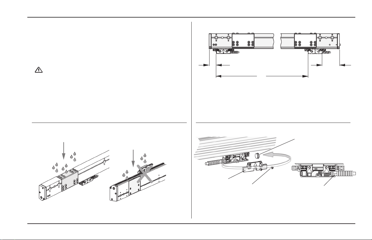
Coolant spray ...
• Encoder lip seals to face away from coolant spray.
Measuring length ...
[1.0”]
25mm
“L”
“L” = Measuring length + [2.0”] 50.8mm nominal over travel
Travel is limited by stops at each end of scale
[2.8”]
71.1mm
• Machine travel can not exceed the encoder measuring length.
• Either limit machine travel or obtain correct length scale.
Changing cable exit direction ...
Plug
Cover plate
T-10 Torx screw (2)
Armor cable hex crimp
• Determine the cable exit direction before installing the encoder.
• To change the cable exit direction; remove the cover plate
and rotate the cable 180°.
3
Acu-Rite Companies Inc.
Page 6
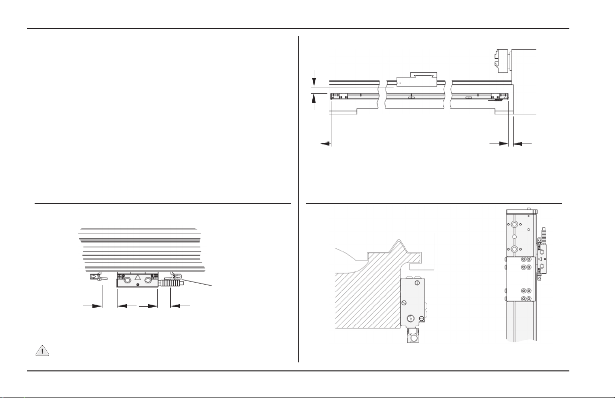
Mounting Information
ENC 250™ SINGLE SECTION
Use this information to plan your Linear Encoder
installation.
• Mount the linear encoders close to machine guide ways to
ensure system accuracy.
• Space between reading head casting and mounting bracket
or surface must not exceed [.188”] 4.7mm.
Alignment bracket removal clearance
Alignment bracket
[1.0]
25mm
[1.0]
25mm
(2)
End of scale clearance requirements
[1.0] 25mm
[5.0]
127mm
[5.0]
127mm
• [1.0] 25mm of clearance is required above the scale case
top surface for access to the expansion cover fasteners.
• A minimum clearance of [5.0] 127mm is required at each
end of the scale case.
Horizontal
mounting
Vertical
mounting
• Allow clearance for alignment bracket removal.
Alignment brackets must not be removed until
•
instructed.
Acu-Rite Companies Inc.
• Mount encoder in a horizontal or vertical position as shown.
• Do not mount flat or inverted.
4
Page 7
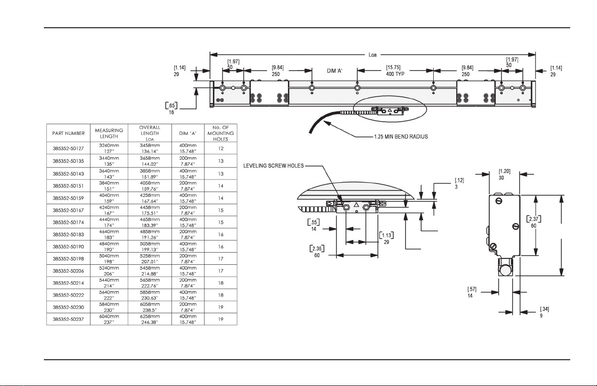
ENC 250™ SINGLE SECTION
Encoder Dimensions
[.83]
21.0
[.37]
9.4
5
Acu-Rite Companies Inc.
[3.2]
81.3
Page 8

Mounting Requirements
ENC 250™ SINGLE SECTION
A variety of mounting conditons can be accommodated.
• The machine configuration determimes the brackets
required to install the encoder.
• Two typical mounting conditions are shown; reading head
mounting plate, and a three piece combination assembly for
mounting the reading head to the machine.
• The [8-32] 4mm SHCS for mounting the reading head is a
standard low head style fastener, supplied with the
mounting hardware.
• The shipping bolts (M5 hex head) must be removed from
the expansion covers prior to beginning the installation.
• Tool requirements are listed on page 18.
Three piece combination bracket ...
Machine
axis
Machine
casting
ENC 250 encoder
Combination
bracket
assembly
Encoder reading
head
Reading head mounting plate ...
Machine
axis
ENC 250 encoder
Machine
casting
Encoder reading
head
Mounting plate
• The mounting plate typically applies to surfaces that are
flush, or slightly offset.
Shipping bolts ...
M5 Shipping
bolts (4)
Expansion
cover (2)
• This combination typically applies to a lathe where the
cross feed over hangs the bed mounting surface.
• A wide range of combination lengths are available.
Acu-Rite Companies Inc.
• Remove the M5 shipping bolts prior to encoder
installation.
6
Page 9

ENC 250™ SINGLE SECTION Encoder Installation Procedure
These steps apply to all mounting conditions. Although this
may not pictorially represent your application, your
installation procedure should follow these steps.
• Adjust drill depths and fastener lengths as required.
The stud tool is used
temporarily to support
the encoder while
locating the mounting
holes
• When instructed on page 10, adjust the leveling set screws
as follows:
1. Insert, but do not tighten the [8-32] 4mm reading head
screws.
2. Use a [.001-.003”] .025 - .076mm shim between the
leveling set screws and mounting surface.
3. Adjust each set screw until a slight drag is felt on the
shim.
4. Evenly tighten the [8-32] 4mm reading head mounting screws.
• Contact your Authorized Distributor should you require
additional assistance.
Most centered scale
mounting hole
Encoder
C
L
Movable axis
(carriage)
• Attach the 1/4-20 installation stud tool.
• Slide the scale case onto the stud at the same hole location.
Stud tool
Align to within [.012”] .3mm TIR to the axis
travel measuring over each hole location
Axis Travel
• Move the machine axis to its center of travel.
• Hold the encoder to the intented mounting location, and
position for the required clearances. Allow minimal
distance required for the reading head brackets.
• Mark the “most centered” scale mounting hole location to
the machine with a center punch.
• Remove encoder, drill / tap location for a [1/4-20 x 1/2”] M6
x 12mm deep.
• Align the top of the scale case.
• Transfer punch the furthest right mounting hole location
before the expansion cover.
• Allow the scale to swing down, drill / tap location for a [1/420 x 1/2”] M6 x 12mm deep.
7
Hole location
Right expansion cover
Acu-Rite Companies Inc.
Page 10

Encoder Installation Procedure
Align to within [.012”] .3mm TIR to the axis
travel measuring over each hole location
Axis Travel
ENC 250™ SINGLE SECTION
Align to within [.012”] .3mm TIR to the axis
travel measuring over each hole location
Axis Travel
Starting hole
[1/4-20 x 1-1/4”] M6 x 30mm SHCS & M6 flat washer
• Attach and align the top of the scale case. Secure the
fastener.
Align to within [.012”] .3mm TIR to the axis
travel measuring over each hole location
Axis Travel
Left expansion cover
[1/4-20 x 1-1/4”] M6 x 30mm SHCS & M6 flat washer
• Align the furthest left mounting hole before the expansion
cover with the furthest right attached hole.
• Transfer punch the left hole location.
• Drill / tap location for a [1/4-20 x 1/2”] M6 x 12mm deep.
• Attach the left end, and align the top of the scale case.
Secure the fastener.
Acu-Rite Companies Inc.
[1/4-20 x 1-1/4”] M6 x 30mm SHCS & M6 flat washer
• Starting at the right end, align the top of the scale case,
and transfer punch each remaining hole location.
• Remove scale, drill / tap locations for a [1/4-20 x 1/2”]
M6 x 12mm deep.
• Attach the scale case, align to within [.012”] .3mm TIR, &
secure all fasteners. Note: Replace stud with fastener.
Run an indicator along the front
face to locate the high point.
Mark the location, and set the
indicator to 0.000”
• Align the front face of the scale case to within [.012”] .3mm
TIR of the axis travel following the next steps.
8
Page 11

ENC 250™ SINGLE SECTION
Example:
high point
Encoder Installation Procedure
Align to within [.012”] .3mm TIR to the axis
travel measuring over each hole location
Axis Travel
Loosen next two
fasteners
• Loosen the next two fasteners to the right of the high point.
• Move indicator to the first hole location, insert two M3 x 25mm
SHSS (leveling set screws).
• Use the leveling screws to align the face to within [.012”] .3mm
to the high point along the axis travel and secure the fastener.
Run indicator along the front
face to align scale case to within
[.012”] .3mm to the axis travel
• Move indicator to the next hole location, and loosen the next
fastener to the right of that fastener. Align this location.
• Repeat the previous steps to align the face at each fastener.
• Return to the high point, and use the same procedure working to
the left end.
• Recheck the scale case top alignment, by starting at the
center hole location, and adjust as necessary.
Dowel pin anchoring ...
Scale case holes are
undersized to insure
accurate centering.
BHCS (16) on each
expansion cover
[5/16”] 8mm Dowel
Pin (2)
• Drill a [.302”] 7.7mm diameter hole through the dowel pin hole
locations at each end of the scale case [.375] 9.5mm deep.
• Use a [.312] 8mm reamer to provide a press fit.
• Insert the dowel pins at each end, with the threaded holes facing
outward.
• Loosen the BHCS (16) on each expansion cover, approximately
[1/8”] 3mm turn each.
9
Acu-Rite Companies Inc.
Page 12

Encoder Installation Procedure
Universal brackets are available from ACU-RITE for
mounting the reading head. SENC 150 & SENC 250
encoders use most of the same reading head brackets.
Custom designed brackets by the installer should be solid,
rigidly assembled components, attached to the machine with
[1/4-20] M6 fasteners minimum.
8-32 Low head SHCS
(2)
ENC 250™ SINGLE SECTION
Slide brackets back
away from the
reading head and
cable
Twist brackets
45° to remove
• Follow the procedure on page 7 to attach the reading head
to the bracket.
• Use allen wrench from set screw adjustment to slide
alignment brackets away from the reading head.
• Remove alignment brackets and save with this manual.
• Move the axis through its full travel. Confirm that the
assembly does not interfere with the machine movement.
Tape Tensioning ...
Tape tension location label
Align center marks
• Return the machine axis to its center of travel.
• Align the center marks on the reading head and scale case by
sliding the reading head and brackets along the case.
• Locate and attach the reading head brackets to the machine.
• Align the bracket mounting holes with the reading head holes,
and secure brackets in place.
Insert the [8-32] M4 SHCS, BUT DO NOT TIGHTEN.
Acu-Rite Companies Inc.
Reading head
• Move the reading head to the tape tensioning position.
• Temporarily attach the reading head cable to the readout.
• Follow the readout manual’s instructions for set up, and
set the encoder and display resolution to .005mm. Set the
readout in metric mode.
10
Page 13

ENC 250™ SINGLE SECTION
Encoder Installation Procedure
End Cap
Remove plastic plug
Compession sleeve
Washer
Thumb screw
• Remove red plastic plug.
• Insert the thumb screw through the washer, compression
sleeve, and into the end cap hole.
• Thread the screw into the holder inside the end cap, but do
not tighten.
M5 SHSS
Thumb screw
• Completely loosen the M5 SHSS, but do not remove.
• Position the readout so that it can be seen while adusting
the thumb screw head.
• Insure that the readout is in metric mode.
Thumb screw
• Tighten the screw until the readout display reads
approximately .05mm.
• Back off the screw until the display stops changing.
• Reset readout to zero and repeat the procedure two more
times. This relaxes the tape before setting the tension.
M5 SHSS
Thumb screw
• Refer to the tensioning value listed on the label on the case.
• Slowly tighten the screw until the display reaches the tensioning
value.
• Fully tighten the M5 SHSS [30-lb-in] 3.4N m.
11
Acu-Rite Companies Inc.
Page 14

Encoder Installation Procedure
Apply silicone grease to plug
and reinsert it
• Remove the thumb screw, sleeve, and washer.
• Apply silicone grease to the plug and reinstall it.
ENC 250™ SINGLE SECTION
Electrical shielding ...
• Connect a ground wire from the terminal on the back of
the readout to the machine or earth ground.
• Attach a ground wire from the machine to a solid earth
ground.
• With the encoder attached to the cable connected to the
readout, check shielding by measuring resistance between
connector housing and scale unit.
Desired value: 1 ohm max.
• With the readout properly mounted, route the cable with
sufficient slack loops for machine movement to the readout.
• Secure cables by fastening with clips or ties.
• Attach the encoder connectors to the readout.
Acu-Rite Companies Inc.
12
Page 15

ENC 250™ SINGLE SECTION
Trouble Shooting
If you experience difficulties with your installation, do the
following to determine the problem.
Checking the Readout
Difficulties on more than one axis are usually associated with
the readout. Follow these steps to determine if your
difficulties are associated with the readout:
• Ensure that the linear encoder connectors are correctly
seated.
• Swap linear encoder cables at the readout to see if the
problem is still shown in the same display.
• If the problem remains in the same display, the readout
may be in error. To determine if that is the problem, repeat
above steps with both encoders, but with only one encoder
connected at a time. This should allow you to determine if
the problem is with the readout or the encoder.
• If the problem follows the connection change, the linear
encoder may be in error.
If the Readout is at fault, refer to “What to do” to arrange for
the parts necessary to repair your system. If a linear encoder
appears to be at fault, proceed with “Checking the Linear
Encoders”.
Checking the Linear Encoders
Problems on a single axis are usually associated with the
linear encoder or its installation. Difficulties can be caused
by improper installation, loose or misaligned bracketry, or a
damaged or inoperable encoder.
Follow these steps to determine the cause of your system
difficulties:
• Confirm that your bracketry and installation does not
interfere with other machine structures through the entire
length of the linear encoder travel.
• Check for loose fasteners. If you find loose fasteners, first
confirm that the linear encoder is installed to the
tolerances specified and then retighten the fasteners as
required.
• Confirm that the linear encoder is installed to the specified
alignment tolerances. If the installation does not meet the
tolerances, reinstall the encoder according to the
“Installation Procedure”.
• Do not attempt to repair the reading head or scale
assembly. The ENC 250 is field serviceable by assembly
replacement only. Attempts to repair the encoder can
permanently damage it and void the warranty.
What to do
If an ACU-RITE linear encoder or readout is found to be at
fault, please contact your Authorized Distributor for
instructions prior to removing the encoders or readout.
13
Acu-Rite Companies Inc.
Page 16

ENC 250™ SINGLE SECTIONMechanical Specifications
Mechanical Specifications Digital
Resolution 5µm [0.0002 in.]
Grating pitch 100µm [0.00393 in]
Scale medium Reflective Metal Tape
Accuracy ± 15µm/M [0.00018 in/ft]
Max. slew speed 1 M/sec [40 in/sec.]
Force required to move
reading head ± 3.3 Newtons [0.75 lbs]
Operating Environment:
Temperature 0° to 40° C [32° to 104°F]
Relative Humidity 20% to 95% (non-condensing)
Storage Environment:
Temperature -40° to 60° C [-40° to 140°F]
Humidity 20% to 95% (non-condensing)
Weight w/cable 1 kg + 3.2kg/M [2.2 lbs. + 0.18 lbs/in] of measuring length
Connecting cable: Length = .61m [2 ft]
Armor Connector: DE-9P
Max. cable length 22.9m [75 ft.] VRO / 10.7m [35 ft.] DRO
Measuring length 3240mm [127”] - 6040mm [237”]
Reference Mark Interval 100mm [3.937”] Distance encrypted
Acu-Rite Companies Inc.
14
Page 17

ENC 250™ SINGLE SECTION
Specifications
Output Signals and Pin-Outs
Digital Differential
Pin 1 Pin 2 Pin 3 Pin 4 Pin 5 Pin 6 Pin 7 Pin 8 Pin 9
N/C Green Yellow Blue Red White Brown Pink Gray
N/C Channel Channel Channel Channel Ground Vcc, + 5.1 Channel Channel
A+ A- B+ B- ± 0.1 VDC R+ R-
15
1
5
6
9
Acu-Rite Companies Inc.
Page 18

Parameter Digital
ENC 250™ SINGLE SECTIONElectrical Specifications
Output Signals
Incremental signals
Signal levels
Reference Mark signals
Signal level
Power Supply
IOH=(High level output current) = 20mA
VOH=(High level output voltage) >2.5Vdc
0°
Channel A+
Channel A-
Channel B+
Channel B-
1
0
1
0
90°
1
0
1
0
Square-wave voltage signals.
Channels A and B, in 90°
quadrature relationship
Differential TTL
Square-wave pulse
Differential TTL
5.1 ± 0.1 VDC @ 140 mA max.
360°
Channel R+
Channel R-
1 Count
(Phased)
1
0
1
0
I
=(Low level output current) = 20mA
OL
VOL=(Low level output voltage) < 0.5Vdc
Acu-Rite Companies Inc.
16
Page 19

ENC 250™ SINGLE SECTION
3 Year Warranty ...
Warranty
Acu-Rite Companies Inc. readouts and precision scales are
warranted to the end user against defects in material and
workmanship, and against any damage that occurs to the
product within three (3) years from the original purchase
date. Acu-Rite Companies Inc. will, at its discretion and
expense, repair or replace the returned item or any of the
item’s component(s) as long as Acu-Rite Companies Inc.
receives notice of the defect or damage within the three (3)
year warranty period.
The foregoing warranty obligations are in lieu of all
expressed and/or implied warranties of fitness or
merchantability or otherwise, and state Acu-Rite Companies
Inc. entire liability and the end user’s exclusive remedy,
under any circumstances, for any claim of damage.
In no event shall Acu-Rite Companies Inc. be liable for
incidental or consequential damages nor shall Acu-Rite
Companies Inc. liablility for claims or damage arising out of
or connected with this warranty or the manufacture, sale,
delivery, or use of the products with which this warranty is
concerned exceed the purchase price of said products.
17
Acu-Rite Companies Inc.
Page 20

Tool Requirements
You will need the following tools to complete the installation:
• 0.001” Dial Indicator with Magnetic Base
• English Hex Wrench Set
• Metric Hex Wrench Set
• Dial Calipers
• Feeler Gage
• Hand Drill
• Hand Tap
• Taps(English): 1/4-20 UNC & #8-32 UNC
• Taps(Metric): M6, M4
• Drills(English): #7 (.201”), #29 (.136”), N (.302”)
• Drills(Metric): 5mm, 3.3mm, 7.7mm
• Reamer(English): .312”
• Reamer(Metric): 8mm
• Transfer Punch Set
• Hammer
• Center Punch
• Phillips Screw Driver
• Flat-tip Screw Driver
* NOTE: Both English and metric mounting hardware have
been supplied. The mounting instructions reference to both.
Tools required depend on the fasteners being used.
ENC 250™ SINGLE SECTION
Acu-Rite Companies Inc.
Tools
18
Page 21

Page 22

Acu-Rite Companies Inc.Acu-Rite Companies Inc.
Acu-Rite Companies Inc.
Acu-Rite Companies Inc.Acu-Rite Companies Inc.
IS ANIS AN
IS AN
IS ANIS AN
ISO 9001ISO 9001
ISO 9001
ISO 9001ISO 9001
CERTIFIEDCERTIFIED
CERTIFIED
CERTIFIEDCERTIFIED
MANUFMANUF
ACTURERACTURER
MANUF
ACTURER
MANUFMANUF
ACTURERACTURER
One Precision Way • Jamestown, NY 14701
Acu-Rite Companies Inc.
104000-028 EDITION C 7/07
 Loading...