

Page 1
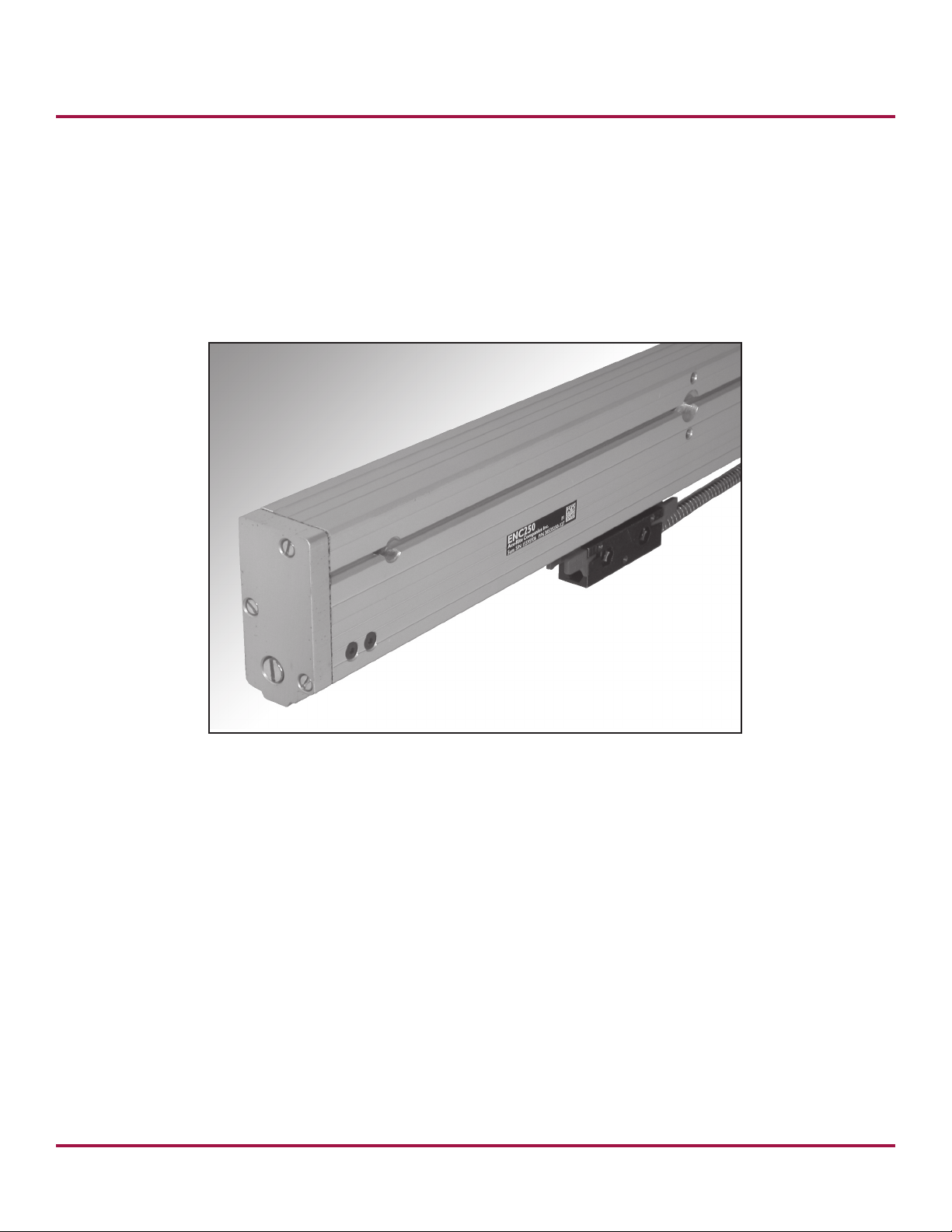
ENC 250TM MULTI-SECTION
REFERENCE MANUAL
Acu-Rite Companies Inc.
Page 2
™
ENC 250
MULTI-SECTION
Table of Contents
Introduction
Bracket availability ...........................................................1
Components supplied .........................................................2
Tool requirements ..............................................................2
Mounting Preparation
Measuring length ................................................................2
Cable exit ............................................................................2
Mounting information ........................................................3
Encoder Dimensions ...........................................................3
Mounting Requirements ....................................................4
Installation
Left end section ...................................................................4
Center section(s).................................................................5
Right end section ................................................................6
Dowel pin anchoring ...........................................................6
Page
Page
Tape .....................................................................................7
Lip seal ................................................................................7
Reading head.......................................................................8
Completing the installation
Tape tensioning................................................................... 9
Specifications
Electrical shielding ...........................................................10
Trouble Shooting ...............................................................10
Mechanical ........................................................................11
Electrical ...........................................................................11
Pin out ...............................................................................12
Hassle-Free Warranty .......................................................12
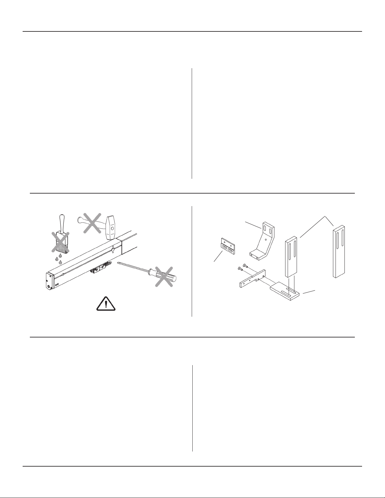
Brackets ...
Off set side
mount bracket
Universal side mounting bracket
(Available in different lengths)
Introduction
The ENC 250 linear encoder provides the accuracy and
reliability of an Acu-Rite Companies Inc. measuring system
with digital output. Features and options include:
• Resolution of [.0002in.] 5µm
• Accuracy grade of [.00018 in/ft] +/-15µm/M
• [2 ft.] .61m armor cable and extension cables up to a
maximum of [75 ft.] 22.9m for a VRO; [35 ft.] 10.7m for a
DRO
• Mounting hardware
• Brackets and accessories
Contact your Authorized Distributor for a complete list of
other products and accessories.
Reading head
mounting plate
Combination
reading head bracket
w/extension
• Installation brackets are available.
• Your authorized distributor can assist you in selecting
brackets for your installation.
For future ordering information or warranty service, record
the linear encoder catalog number located on the scale
assembly tag, and the serial number from the reading head
tag.
Catalog No. Serial No.
Axis: _______________ _________________
Tape tension value: __________________________________
Date of purchase: ___________________________________
Distributor: ___________________________________
Address: ___________________________________
Telephone: ___________________________________
1
Acu-Rite Companies Inc.
Page 3
ENC 250
™
MULTI-SECTION
Components
Each unit should consist of the following boxes:
Scale Section Boxes:
• Right End Section
• Left End Section
• Center Sections (One or more boxes depending on length)
Common Components Box:
• Scale Measuring Tape (Coiled On Spool)
• Lipseals (Coiled On Spool)
• Reading Head
• Mounting Hardware with RTV and Silicone Grease
• Reference Manual
* NOTE: Both English and metric mounting hardware have
been supplied. The mounting instructions reference to both.
Tools required depend on the fasteners being used.
Mounting Preparation
Tools
You will need the following tools to complete the
installation:
• 0.001” Dial Indicator with Magnetic Base
• English Hex Wrench Set
• Metric Hex Wrench Set
• Dial Calipers
• Feeler Gage
• Hand Drill
• Hand Tap
• Taps (English): 1/4-20 UNC & #8-32 UNC
• Taps (Metric): M6, M4
• Drills (English): #7 (.201”), #29 (.136”), N (.302”)
• Drills (Metric): 5mm, 3.3mm, 7.7mm
• Reamer (English): .312”
• Reamer (Metric): 8mm
• Transfer Punch Set
• Hammer
• Center Punch
• Phillips Screw Driver
• Flat-tip Screw Driver
• Torque Wrench
Measuring length ...
Please follow these preparation guide lines.
• Understand your mounting requirements.
• Mount with lip seals down and away from the work area.
• Brackets should be kept as short as possible and rigid.
• Surfaces must be in good condition, clean, and free of dirt.
Remove paint from machined mounting surfaces.
• Locate the machine’s center of travel on the axis that
the encoder will be mounted to. Move the axis to the
center of travel prior to installing the encoder. Mark
a reference line on the axis so that it can easily be
returned to the center of travel.
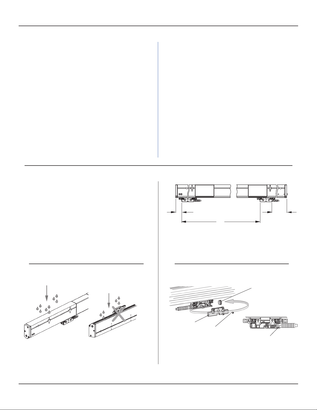
Coolant spray ...
[1.0”]
25mm
“L”
“L” = Measuring length + [2.0”] 50.8mm nominal over travel
Travel is limited by stops at each end of scale
[2.8”]
71.1mm
• Machine travel can not exceed the encoder measuring
length.
• Either limit machine travel or obtain correct length scale.
Changing cable exit direction ...
Plug
Cover plate
T-10 Torx screw (2)
• Encoder lip seals to face away from coolant spray.
Armor cable hex crimp
• Determine the cable exit direction before installing the reading
head.
• To change the cable exit direction; remove the cover plate
and rotate the cable 180°.
2
Acu-Rite Companies Inc.
Page 4
ENC 250
™
MULTI-SECTION
Mounting Information
Use this information to plan your Linear Encoder installation.
• Mount the linear encoders close to machine guide ways to
ensure system accuracy.
• Space between reading head casting and mounting bracket
or surface must not exceed [.188”] 4.7mm.
Alignment bracket removal clearance
Alignment bracket
[1.0]
25mm
[1.0]
25mm
(2)
End of scale clearance requirements ...
[1.0] 25mm
[5.0]
127mm
[5.0]
127mm
• Minimum clearance is required above the scale case top.
• A minimum clearance of [5.0] 127mm is required at each
end of the scale case.
Positioning ...
Horizontal
mounting
Vertical
mounting
• Allow clearance for alignment bracket removal.
Alignment brackets must not be removed until
•
instructed.
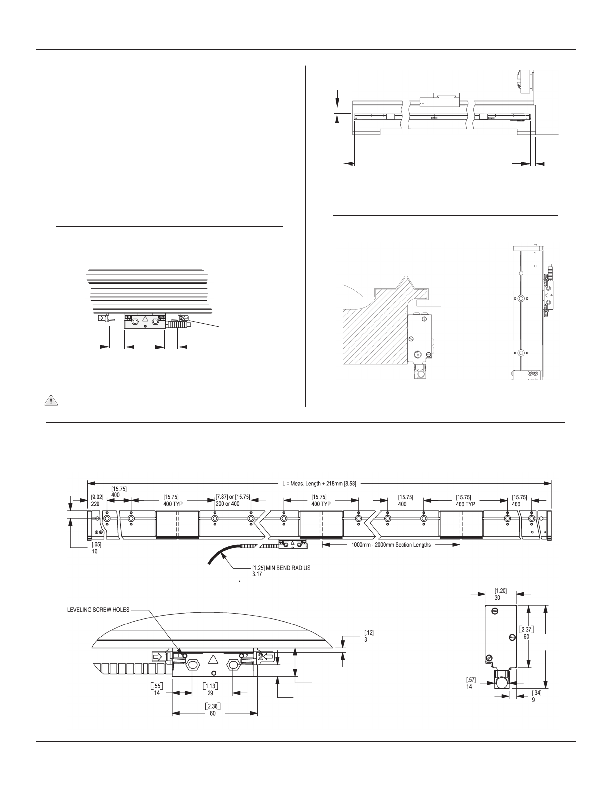
Encoder Dimensions
• Mount encoder in a horizontal or vertical position as shown.
• Do not mount flat or inverted.
[.83]
21.0
[.37]
9.4
[3.2]
81.3
3
Acu-Rite Companies Inc.
Page 5

ENC 250
™
MULTI-SECTION
Mounting Requirements
A variety of mounting conditions can be accommodated.
• The machine configuration determines the brackets
required to install the encoder.
• Two typical mounting conditions are shown; reading head
mounting plate, and a three piece combination assembly for
mounting the reading head to the machine.
• The [8-32] 4mm SHCS for mounting the reading head is a
standard low head style fastener, supplied with the
mounting hardware.
• Tool requirements are listed on page 2.
• Due to the long length of the encoder sections, the
installation illustrations have been modified.
In most cases, the sections have been shorten to
accommodate the information that they are presenting.
Please keep this in mind as the encoder is being installed.
Three piece combination bracket ...
Machine
axis
Machine
casting
• This combination typically applies to a lathe where the
cross feed over hangs the bed mounting surface.
• A wide range of combination lengths are available.
ENC 250 encoder
Combination
bracket
assembly
Encoder reading
head
Scale Case Installation Procedure
Left end section installation
Roll Pin
Left end section
Insert roll pin with open slot
• Tap two roll pins into the extruded slots in the “left end
section” as shown. Pins should protrude approximately [5/8”]
15.87mm.
• The seams on the roll pins face towards the inside of the
scale case.
• Repeat this step for all middle scale sections, inserting the
roll pins into the right end of each.
Left end
section
• Hold the left end section against the selected mounting
surface and transfer punch one mounting hole.
• Remove section, drill and tap the location for a
[1/4-20 x 1/2”] M6 x12mm deep minimum.
• Attach the section to the machine, and align the top
surface to within [.012”] .3mm of the axis travel.
Measuring directly over each mounting hole location.
• Transfer punch the second mounting hole. Remove the
section; drill and tap second hole location for a
[1/4-20 x 1/2”] M6 x12mm deep.
Enlarged end
view
facing in as shown
Transfer punch (1)
mounting hole location to
the machine surface
Reading head mounting plate ...
Machine
axis
ENC 250 encoder
Machine
casting
Encoder reading
head
Mounting plate
• The mounting plate typically applies to surfaces that are
flush, or slightly offset.
RTV
Scale clip
Seated end of pin
Sealant groves (2)
• Apply RTV Silicone Rubber to the two sealant grooves in
the left end section. The sealant must be applied on all
three sides of the case. Seal the seated ends of the spring
pins. Keep the end and inside of the section free of
sealant.
• Slide the scale clip over the end of the scale section to the
stop machined in the scale case. There is sufficient spring
in the clip to clamp it securely around the case.
• Clean off any excess RTV on the outside of the case.
4
Acu-Rite Companies Inc.
Page 6

™
ENC 250
MULTI-SECTION
[1/4-20 x 1-1/4”]
M6 x 30mm
SHCS and washer
• Attach this section to the machine using two [1/4-20 x
1-1/4”] M6 x 30mm SHCS and washers provided in the
hardware kit.
• Align the top of the section parallel to the axis travel to
within [.012”] .3mm and secure the fasteners.
Center section installation
Center scale
section
2mm Spacer
Scale clip
2mm Spacer
Roll pins installed
Transfer punch
furthest mounting
hole
RTV
This end first
Center section(s)
• Apply RTV to the two sealant grooves in the right end on
all three sides as done previously. Seal the seated ends of
the spring pins, keeping the end and inside of the section
free of sealant.
• Slide the scale clip over the end of the scale section up to
the stop in the scale case.
• Clean off any excess RTV on the outside of the case.
• Now apply RTV Silicone Rubber to the sealant grooves in
the left end keeping the end and inside of the section free
of sealant.
• Center sections can be mounted in random order.
• Place the 2mm spacer provided in the hardware kit into
the scale clip as shown.
• With the roll pins already installed, insert the left end of
the center section into the scale clip and butt it to the
mounted end section. Tap the end of the center section
with a soft hammer to seat it against the 2mm spacer.
• Align the top of the section parallel to the axis travel to
within [.012”] .3mm. Transfer punch the furthest right
end mounting hole to the mounting surface.
• Remove the center section, drill and tap the location for
an [1/4-20 x 1/2 “] M6 x12mm deep.
[1/4-20 x 1/2 “]
M6 x12mm SHCS
and washer
• Re-insert the center section back into the scale clip as
done previously, seating it against the 2mm spacer.
• Attach the right end to the machine but do not tighten.
• Transfer punch remaining mounting holes by aligning the
top surface to within [.012”] .3mm to the axis travel over
each mounting hole. Remove the center section, drill and
tap the locations for an [1/4-20 x 1/2 “] M6 x12mm deep.
• Reinsert the center section back into the scale clip as done
previously, seating it against the 2mm spacer.
• Attach the right end to the machine but do not tighten.
Clean off any excessive RTV sealant.
To be within [.012”] .3mm to the
axis travel
End
section
Center section
[1/4-20 x 1/2 “]
M6 x12mm SHCS
and washer
• Align the top surface to within [.012”] .3mm to the axis
travel measuring over each mounting hole. Secure the
scale case in place maintaining the alignment.
• Turn the handle of the 2mm spacer forward and remove it
through the bottom of the scale clip.
Remaining section(s) installation
• Mount any remaining center sections and the right end
section to the machine repeating this procedure. Use the
2mm spacer each time to set the required gap between
each section. Complete the next step prior to drilling and
tapping the right end mounting holes.
5
Acu-Rite Companies Inc.
Page 7

ENC 250
™
MULTI-SECTION
End to end distance must be
xx40mm ± 2mm
Suggested second location
• Check for proper spacing between sections. Using a tape
measure, record the over all length of the mounted scale
sections (no end caps). Convert the length to millimeters
by multiplying by 25.4. If the sections are mounted
correctly, the last two digits of your measurement should
be very close to 40 mm; (e.g. 6640 mm, 8040 mm, 10840
mm etc.). If this distance is off by more than two
millimeters from nominal (e.g. 6637 mm, 6643 mm) shift
the location of the right end section to bring it within the
nominal distance.
Scale face alignment
Run an indicator along the front
face to locate the high point.
Mark the location, and set the
indicator to 0.000” [0.0mm]
• To align the front face of the scale case to the axis travel,
first locate the high point. This is the TIR point furthest
away from the mounting surface along the axis travel.
Suggested first location
Move the indicator to a different
location on the face of the scale case
• Recheck the scale face alignment at a second location to
insure the encoder is parallel. Use the leveling screws for
further alignment if necessary.
Top surface
• Following the face alignment procedure, the top alignment
must be rechecked. Follow the previous steps placing the
indicator over each mounting hole.
Dowel pin anchoring ...
[5/16”] 8mm Dowel
Pin (2)
Loosen next two
Example:
high point
fasteners
• Loosen the next two fasteners to the right of the high point.
• Move indicator to the first hole location, insert two M3 x 25mm
SHSS (leveling set screws).
• Use the leveling screws to align the face to within [.012”]
.3mm to the high point along the axis travel and secure the
fastener.
• Move indicator to the next hole location, then loosen the
next fastener to the right. Align this location to within
[.012”] .3mm. Continue alignment with the remaining
fasteners.
• Return to the high point, and use the same procedure
working out to the left end.
Threaded hole
Scale case holes are undersized to
insure accurate centering.
• Drill a [.302”] 7.7mm diameter hole through the dowel pin
hole locations at each end of the scale case [3/8”] 9.5mm
deep.
• Use a [.312] 8mm reamer to provide a press fit.
• Insert the dowel pins at each end, with the threaded hole
facing outward.
6
Acu-Rite Companies Inc.
Page 8

™
ENC 250
MULTI-SECTION
Scale Tape Installation
End view of
tee slot
Scale Tape
• Apply a small amount of silicone grease – as a sealant - to
the two M3 x 8mm FHSS.
• Insert the screws through the scale case and thread into
the anchor block. Tighten fasteners completely.
Scale Tensioner
• Place the Scale Tensioner into the tee slot on the left end
of the scale case.
• Retrieve the scale tape from the carton. The scale tape is
shipped in a protective plastic coil. Do not uncoil the tape.
It should be uncoiled as it is inserted into the case. The
tape must be kept free of fingerprints and contaminants.
It is best to wear clean cotton gloves when handling it. If
necessary, the scale tape may be cleaned with cotton cloth
soaked in alcohol or acetone.
• Hook the boss on the scale tensioner through the square
hole in the scale tape to capture the tape and slide the
scale tensioner into the scale case. Note – the gold
rulings on the scale tape must face into the scale
cavity.
End view of
tee slot
Left end of
travel mark
[0.65”] 16.5mm
Center of
travel mark
Equal Equal
Right end of
travel mark
[2.46”] 62.5mm
• Draw a line onto the front of the scale case at a distance of
[0.65”] 16.5mm from the left end. Similarly draw a line
onto the front of the scale case at a distance of [2.46”]
62.5mm from the right end. These are the end-of-travel
marks. The ends of the reading head must not travel
beyond those lines.
• Find the center distance between the two lines and draw
another line onto the front of the scale case. This line
represents the center of travel. The reading head must be
mounted so that it is centered under this line when the
machine carriage is located at the center of its axis travel.
Retainer clip
0.XXX mm
Tape tension value
Anchor block
• Before inserting the tape completely into the case, check
the tension value on the backside of the scale tape at the
anchor end. Check the value on the label attached to the
right end section, and verify that it is correct.
• The two M3 x 8mm Flat Head Socket Screws must be
removed from the scale anchor block. Continue pushing
the scale tape into the case until the anchor end is flush
with the left side of the case. Make sure that all the
scale tape retainer clips go into the T-slot. If the scale
tape can not be inserted completely by pushing at one end,
the scale tensioner may be pulled along the case with a
small steel ruler from the bottom of the scale case.
Lip seal keying feature
• Insert a lip seal into the front keyhole slot (the one closest
to the scale tape) until it protrudes at least 1/2” [12mm]
from the far side. Lip seals must be installed with the
keying features opposing each other.
This view shows lip seal orientation.
It is not required for them to be inter
locked during installation.
• Similarly, insert the rear lip seal. Make sure that the lip
seals are not under excessive tension in the case.
Normally, the lip seal can be pulled through completely
with a pair of needle-nose pliers.
7
Acu-Rite Companies Inc.
Page 9

™
ENC 250
Insert straight pins here
to fasten ends of lip seals
MULTI-SECTION
Approximately [1/8”]
3mm over hang
Straight pin
If necessary pull the lip seal along at different points
along the inserted length. Insert the 4 straight pins from
the hardware kit into the ends of the lip seal grooves to
keep the lip seals from pulling away from the ends of the
scale case. Trim the lip seals ends with a pair of scissors
so that there is an overhang of approximately [1/8”] 3mm
at each end.
M3 x 12 CHMS
• Attach the right end cap with M3 x 12 CHM screws
provided in the hardware kit. Tighten these screws
securely to compress the end cap gasket.
Changing cable exit direction ...
Plug
• Support the reading head by hand, and remove the
alignment brackets by sliding them away from the reading
head and twisting them 45° to remove them from the
scale case. Gently pry them away from the reading head
with a small screw driver if needed.
Reading head
• Slide the reading head onto the scale case to the center of
travel mark on the case.
Cover plate
T-10 Torx screw (2)
Armor cable hex crimp
• Determine the cable exit direction before installing the
reading head.
• To change the cable exit direction; remove the cover plate
and rotate the cable 180°.
Numbers on reading head
casting
• The reading head is shipped attached to the installation
tool. Push the protruding roll pins of the reading head
installation tool assembly into the left end of the scale
case. Push on securely to close the gap between the scale
sections. The number indicators of the reading head
are always facing out.
• Reinstall the alignment brackets by inserting each at 45°
and twist to insert them into grooves on the bottom of
scale case. Slide brackets against the reading head until
they clip into place. Numbers and letters on reading head
casting and alignment brackets must correspond.
• Align the triangle on the reading head with the center-oftravel mark previous placed on the scale.
• Return the axis back to its center of travel, and
lock in place.
8
Acu-Rite Companies Inc.
Page 10

™
ENC 250
MULTI-SECTION
Installing the reading head
The reading head must be mounted in the same location as
it is held by the alignment brackets. To attach the reading
head to the mounting surface, follow these steps:
• Custom designed brackets by the installer should be solid,
and rigidly assembled. Attach brackets to the machine
with [1/4-20] M6 fasteners minimum. Allow clearance for
removing alignment brackets once the reading head has
been installed. Also, allow a small amount of clearance
between the reading head and its mounting surface for
setting the leveling screws. For custom brackets, transfer
punch the two head mounting holes on the bracket and tap
these holes for [8-32 x 1/2”] M4 x 12mm deep minimum.
To mount the reading head proceed as follows:
• Insert, but do not tighten the [8-32] M4 reading head
screws.
• Place a [.001 - .003”] .025 - .076mm shim between the
leveling set screws and mounting bracket.
• Adjust each screw until a slight drag is felt on the shim.
• Evenly tighten the [8-32] M4 reading head mounting
screws so that the head does not shift or twist. Remove
the alignment brackets as done previously.
• Verify the reading head is able to move through the entire
length of machine travel without interference.
• Move the axis so that the reading head is at the tape
tensioning position indicated by the tension label on the
right side of the scale.
• Set the readout’s display and encoder resolution to .005
mm. See readout reference manual for setting resolution.
Polyurethane
compression spring
Flat washer
M4
Thumbscrew
Tensioning hole
• Remove tensioning hole plug from the right end cap.
• Insert the M4 thumbscrew from the hardware kit through
the washer and polyurethane compression spring into the
tensioning hole. Turn the thumbscrew until it engages the
scale tensioner inside the scale case.
M4
Thumbscrew
Completing the
installation
M3 x 12 CHMS
• Remove the Reading Head shipping tool from the end of
the scale case. Attach the left end cap with M3 x 12 CHM
screws provided in the hardware kit. Tighten these screws
securely to compress the end cap gasket.
M5 SHSS
• Turn the thumbscrew clockwise to tension the tape until
the display has changed approximately .050mm.
Carefully back off the thumbscrew until the display stops
changing. Reset the display to zero.
• Repeat this procedure two to three times to put the tape
in a relaxed, slack-free position.
• Slowly tighten the thumbscrew until the display reaches
the tensioning value shown on the scale label.
• Tighten the M5 SHSS on the right side of the case to
30 in-lb. [3.4Nm]
• THE M5 SHSS MUST BE TIGHTENED SECURELY
AFTER TENSIONING TO PREVENT TAPE
SLIPPAGE.
• Unscrew and remove the knurled tensioning screw
assembly from the scale case.
9
Acu-Rite Companies Inc.
Page 11

ENC 250
™
MULTI-SECTION
Trouble Shooting
Apply silicone grease to plug
and reinsert it
• Coat the plastic plug with silicone grease and install it
into the tensioning hole.
• This completes the installation of the ENC 250.
• With the readout properly mounted, route the cable with
sufficient slack loops for machine movement to the readout.
• Secure cables by fastening with clips or ties.
• Attach the encoder connectors to the readout.
If you experience difficulties with your installation, do the
following to determine the problem.
Checking the Readout
Difficulties on more than one axis are usually associated
with the readout. Follow these steps to determine if your
difficulties are associated with the readout:
• Ensure that the linear encoder connectors are correctly
seated.
• Swap linear encoder cables at the readout to see if the
problem is still shown in the same display.
• If the problem remains in the same display, the readout
may be in error. To determine if that is the problem,
repeat above steps with both encoders, but with only one
encoder connected at a time. This should allow you to
determine if the problem is with the readout or the
encoder.
• If the problem follows the connection change, the linear
encoder may be in error.
If the Readout is at fault, refer to “What to do” to arrange
for the parts necessary to repair your system. If a linear
encoder appears to be at fault, proceed with “Checking the
Linear Encoders”.
Checking the Linear Encoders
Problems on a single axis are usually associated with the
linear encoder or its installation. Difficulties can be caused
by improper installation, loose or misaligned bracketry, or
a damaged or inoperable encoder.
Electrical shielding ...
• Connect a ground wire from the terminal on the back of
the readout to the machine or earth ground.
• Attach a ground wire from the machine to a solid earth
ground.
• With the encoder attached to the cable connected to the
readout, check shielding by measuring resistance
between connector housing and scale unit.
Desired value: 1 ohm max.
Follow these steps to determine the cause of your system
difficulties:
• Confirm that your bracketry and installation does not
interfere with other machine structures through the
entire length of the linear encoder travel.
• Check for loose fasteners. If you find loose fasteners, first
confirm that the linear encoder is installed to the
tolerances specified and then retighten the fasteners as
required.
• Confirm that the linear encoder is installed to the
specified alignment tolerances. If the installation does
not meet the tolerances, reinstall the encoder according to
the “Installation Procedure”.
• Do not attempt to repair the reading head or scale
assembly. The ENC 250 is field serviceable by assembly
replacement only. Attempts to repair the encoder can
permanently damage it and void the warranty.
What to do
If an ACU-RITE linear encoder or readout is found to be at
fault, please contact your Authorized Distributor for
instructions prior to removing the encoders or readout.
10
Acu-Rite Companies Inc.
Page 12

™
ENC 250
MULTI-SECTION
Mechanical Specifications
Mechanical Specifications Digital
Resolution 5µm [0.0002 in.]
Grating pitch 100µm [0.00393 in]
Scale medium Reflective Metal Tape
Accuracy @ 20° C ± 15µm/M [0.00018 in/ft]
Max. slew speed 1 M/sec [40 in/sec.]
Force required to move
reading head ± 3.3 Newtons [0.75 lbs]
Operating Environment:
Temperature 0° to 40° C [32° to 104°F]
Relative Humidity 20% to 95% (non-condensing)
Storage Environment:
Temperature -40° to 60° C [-40° to 140°F]
Humidity 20% to 95% (non-condensing)
Weight w/cable 1 kg + 3.2kg/m [2.2 lbs. + 0.18 lbs/in] of measuring length
Connecting cable: Length = .61m [2 ft]
Armor Connector: DE-9P
Max. cable length 22.9m [75 ft.] VRO / 10.7m [35 ft.] DRO
Measuring length 6240mm [246”] - 19,640mm [773”]
Reference Mark Interval 100mm [3.937”] Distance encrypted
Electrical Specifications
Parameter Digital
Output Signals
Incremental signals
Signal levels
Reference Mark signals
IOH=(High level output current) = 20mA
VOH=(High level output voltage) >2.5Vdc
0°
Channel
A+
Channel A-
Channel
B+
Channel B-
1
0
1
0
90°
1
0
1
0
Square-wave voltage signals.
Channels A and B, in 90°
quadrature relationship
Differential - TTL
Square-wave pulse
360°
Channel R+
Channel R-
1
0
1
0
1 Count
(Phased)
I
=(Low level output current) = -20mA
OL
VOL=(Low level output voltage) < 0.5Vdc
Signal level
Power Supply
Differential - TTL
5.1 ± 0.1 VDC @ 140 mA max.
11
Acu-Rite Companies Inc.
Page 13

™
ENC 250
MULTI-SECTION
Digital Differential
Pin 1 Pin 2 Pin 3 Pin 4 Pin 5 Pin 6 Pin 7 Pin 8 Pin 9
N/C Green Yellow Blue Red White Brown Pink Gray
N/C Channel Channel Channel Channel Ground Vcc, + 5.1 Channel Channel
A+ A- B+ B - ± 0.1 VDC R+ R-
1
6
5
9
Hassle-Free Warranty
Acu-Rite Companies Inc. readouts and precision scales are warranted to the end user against defects in material and workmanship and
against any damage that occurs to the product within three (3) years from the original purchase date. Acu-Rite Companies Inc. will, at
its discretion and expense, repair or replace the returned item or any of the item’s component(s) as long as Acu-Rite Companies Inc.
receives notice of the defect or damage within the three (3) year warranty period.
The foregoing warranty obligations are in lieu of all expressed and/or implied warranties of fitness or merchantability or otherwise, and
state Acu-Rite Companies Inc.’s entire liability and the end user’s exclusive remedy, under any circumstances, for any claim of damage.
In no event shall Acu-Rite Companies Inc. be liable for incidental or consequential damages nor shall Acu-Rite Companies Inc.’s liability
for claims or damage arising out of or connected with this warranty or the manufacture, sale, delivery, or use of the products with which
this warranty is concerned exceed the purchase price of said products.
Acu-Rite Companies Inc.Acu-Rite Companies Inc.
Acu-Rite Companies Inc.
Acu-Rite Companies Inc.Acu-Rite Companies Inc.
IS ANIS AN
IS AN
IS ANIS AN
ISO 9001ISO 9001
ISO 9001
ISO 9001ISO 9001
CERTIFIEDCERTIFIED
CERTIFIED
CERTIFIEDCERTIFIED
MANUFMANUF
ACTURERACTURER
MANUF
ACTURER
MANUFMANUF
ACTURERACTURER
One Precision Way • Jamestown, NY 14701
Acu-Rite Companies Inc.
104001-115 EDITION C 7/07
12
Acu-Rite Companies Inc.
 Loading...