

Page 1
DRO 203 DRO 300
Operating Instructions
Digital Readout
English (en)
03/2018
Page 2

Contents
Contents
1 Fundamentals..................................................................................................................................13
2 Safety...............................................................................................................................................21
3 Transport and storage....................................................................................................................27
4 Mounting......................................................................................................................................... 31
5 Installation.......................................................................................................................................37
6 Fundamentals of positioning........................................................................................................ 43
7 Basic operation...............................................................................................................................51
8 Commissioning............................................................................................................................... 65
9 Milling specific operations............................................................................................................ 95
10 Turning specific operations......................................................................................................... 119
11 Programming................................................................................................................................ 131
12 Measured value output................................................................................................................139
13 Operating the IOB 610................................................................................................................. 143
14 Settings..........................................................................................................................................165
15 Service and maintenance............................................................................................................179
16 What to do if.................................................................................................................................183
17 Removal and disposal..................................................................................................................185
18 Specifications................................................................................................................................187
2
ACU-RITE | DRO 203, DRO 300 | Operating Instructions | 03/2018
Page 3

Contents
1 Fundamentals..................................................................................................................................13
1.1 About these instructions.....................................................................................................................14
1.2 Information on the product................................................................................................................ 14
1.3 Notes on reading the documentation............................................................................................... 15
1.4 Storage and distribution of the documentation...............................................................................16
1.5 Target group for the instructions....................................................................................................... 16
1.6 Notes in this documentation..............................................................................................................17
1.7 Symbols and fonts used for marking text........................................................................................ 19
2 Safety...............................................................................................................................................21
2.1 Overview............................................................................................................................................... 22
2.2 General safety precautions................................................................................................................. 22
2.3 Intended use.........................................................................................................................................22
2.4 Improper use........................................................................................................................................ 22
2.5 Personnel qualification........................................................................................................................ 23
2.6 Obligations of the operating company..............................................................................................24
2.7 General safety precautions................................................................................................................. 24
2.7.1 Symbols in the instructions..................................................................................................... 25
2.7.2 Symbols on the product.......................................................................................................... 25
2.7.3 Electrical safety instructions....................................................................................................26
3 Transport and storage....................................................................................................................27
3.1 Overview............................................................................................................................................... 28
3.2 Unpacking............................................................................................................................................. 28
3.3 Items supplied and accessories..........................................................................................................28
3.4 In case of damage in transit...............................................................................................................29
3.5 Repackaging and storage....................................................................................................................30
ACU-RITE | DRO 203, DRO 300 | Operating Instructions | 03/2018
3
Page 4

Contents
4 Mounting......................................................................................................................................... 31
4.1 Overview............................................................................................................................................... 32
4.2 Assembly...............................................................................................................................................32
4.3 Mounting on Single-Pos stand...........................................................................................................33
4.4 Mounting on Multi-Pos holder........................................................................................................... 34
4.5 Mounting in a mounting frame..........................................................................................................35
4.6 Mounting a cover.................................................................................................................................36
5 Installation.......................................................................................................................................37
5.1 Overview............................................................................................................................................... 38
5.2 General information............................................................................................................................. 38
5.3 Product overview................................................................................................................................. 39
5.4 Connecting the encoders....................................................................................................................40
5.5 Connecting an accessory.................................................................................................................... 40
5.6 Connecting a USB device................................................................................................................... 41
5.7 Connecting the line voltage................................................................................................................42
6 Fundamentals of positioning........................................................................................................ 43
6.1 Overview............................................................................................................................................... 44
6.2 Datums.................................................................................................................................................. 44
6.3 Actual position, nominal position, and Distance-To-Go.................................................................. 44
6.4 Absolute workpiece positions............................................................................................................ 45
6.5 Incremental workpiece positions....................................................................................................... 46
6.6 Zero angle reference axis.................................................................................................................... 47
6.7 Reading head position........................................................................................................................ 48
6.8 Encoder reference marks.....................................................................................................................49
4
ACU-RITE | DRO 203, DRO 300 | Operating Instructions | 03/2018
Page 5

Contents
7 Basic operation...............................................................................................................................51
7.1 Overview............................................................................................................................................... 52
7.2 Front panel and keys...........................................................................................................................52
7.3 Switch-on/Switch-off...........................................................................................................................53
7.3.1 Switch-on..................................................................................................................................53
7.3.2 Switch-off................................................................................................................................. 53
7.4 User interface....................................................................................................................................... 54
7.4.1 Display layout...........................................................................................................................54
7.4.2 Soft keys.................................................................................................................................. 55
7.4.3 Graphic positioning aid............................................................................................................ 56
7.4.4 Operating modes..................................................................................................................... 56
7.4.5 Stopwatch................................................................................................................................ 57
7.4.6 Calculator..................................................................................................................................57
7.4.7 Help..........................................................................................................................................58
7.4.8 Data input forms......................................................................................................................59
7.4.9 Reference mark evaluation...................................................................................................... 59
7.4.10 Selecting a specific reference mark........................................................................................ 61
7.4.11 Error messages........................................................................................................................61
7.4.12 Setup menus............................................................................................................................61
7.5
User Management................................................................................................................................. 62
7.5.1 Supervisor Login...................................................................................................................... 62
7.5.2 User Job Settings.................................................................................................................... 62
ACU-RITE | DRO 203, DRO 300 | Operating Instructions | 03/2018
5
Page 6

Contents
8 Commissioning............................................................................................................................... 65
8.1 Overview............................................................................................................................................... 66
8.2
Installation Guide..................................................................................................................................67
8.3
Installation Setup..................................................................................................................................68
8.3.1 File management..................................................................................................................... 68
8.3.2 Encoder Setup......................................................................................................................... 74
8.3.3 Display Configuration...............................................................................................................76
8.3.4 Readout Settings......................................................................................................................77
8.3.5 Diagnostics...............................................................................................................................78
8.3.6 Display Color Scheme..............................................................................................................78
8.3.7 Factory defaults....................................................................................................................... 79
8.3.8 Error Compensation.................................................................................................................79
8.3.9 Backlash compensation........................................................................................................... 84
8.3.10 Spindle settings........................................................................................................................84
8.3.11 Switching outputs.................................................................................................................... 84
8.3.12 CSS settings.............................................................................................................................85
8.4 Job Setup..............................................................................................................................................85
8.4.1 Units.........................................................................................................................................85
8.4.2 Scale Factor............................................................................................................................. 86
8.4.3 Edge Finder..............................................................................................................................87
8.4.4 Diameter Axes......................................................................................................................... 87
8.4.5 Measured Value Output...........................................................................................................88
8.4.6 Graphic positioning aid............................................................................................................ 88
8.4.7 Status Bar Settings.................................................................................................................. 89
8.4.8 Stopwatch................................................................................................................................ 89
8.4.9 Skew Compensation for Mill applications............................................................................... 90
8.4.10 Remote Switch........................................................................................................................ 91
8.4.11 DRO View Settings..................................................................................................................92
8.4.12 Display Settings....................................................................................................................... 93
8.4.13 System Information..................................................................................................................94
8.4.14 Language..................................................................................................................................94
6
ACU-RITE | DRO 203, DRO 300 | Operating Instructions | 03/2018
Page 7

Contents
9 Milling specific operations............................................................................................................ 95
9.1 Overview............................................................................................................................................... 96
9.2 1/2 soft key...........................................................................................................................................96
9.3 Tool Table.............................................................................................................................................. 97
9.3.1 Soft keys.................................................................................................................................. 97
9.3.2 Importing and exporting...........................................................................................................97
9.3.3 Tool compensation................................................................................................................... 98
9.3.4 Entering tool data.................................................................................................................... 99
9.3.5 Selecting a tool......................................................................................................................100
9.4 Setting a datum................................................................................................................................. 100
9.4.1 Setting a workpiece datum without using the probing function............................................101
9.4.2 Probing with a tool................................................................................................................ 101
9.4.3 Probing with an edge finder..................................................................................................105
9.5 Presetting a target position.............................................................................................................. 108
9.5.1 Absolute distance preset.......................................................................................................109
9.5.2 Incremental distance preset..................................................................................................111
9.6 Features...............................................................................................................................................112
9.6.1 Circle and linear patterns.......................................................................................................113
9.7 Z/W coupling......................................................................................................................................118
ACU-RITE | DRO 203, DRO 300 | Operating Instructions | 03/2018
7
Page 8

Contents
10 Turning specific operations......................................................................................................... 119
10.1 Overview............................................................................................................................................. 120
10.2 Tool display icon................................................................................................................................ 120
10.3 Tool table.............................................................................................................................................120
10.3.1 Importing and exporting.........................................................................................................120
10.3.2 Setting tool offsets................................................................................................................ 120
10.3.3 Selecting a tool......................................................................................................................122
10.4 Setting a datum................................................................................................................................. 123
10.4.1 Setting a datum manually......................................................................................................123
10.4.2 Setting a datum using the Lock Axis function.......................................................................124
10.5 Taper Calculator..................................................................................................................................124
10.6 Presets................................................................................................................................................. 126
10.7 Diameter and radius measurements................................................................................................127
10.8 Vectoring............................................................................................................................................. 128
10.9 Z coupling........................................................................................................................................... 128
11 Programming................................................................................................................................ 131
11.1 Overview............................................................................................................................................. 132
11.2 Creating a new Program...................................................................................................................132
11.3 Creating features in a program........................................................................................................ 133
11.3.1 Creating a Tool step...............................................................................................................133
11.3.2 Creating a Datum step.......................................................................................................... 133
11.3.3 Creating a Preset step...........................................................................................................133
11.3.4 Creating a Position step.........................................................................................................134
11.3.5 Creating a Circle Pattern step................................................................................................134
11.3.6 Creating a Linear Pattern step...............................................................................................134
11.4 Editing steps.......................................................................................................................................135
11.5 Editing a Program..............................................................................................................................136
11.6 Opening the graphical view..............................................................................................................136
11.7 Running a program............................................................................................................................137
8
ACU-RITE | DRO 203, DRO 300 | Operating Instructions | 03/2018
Page 9

Contents
12 Measured value output................................................................................................................139
12.1 Overview............................................................................................................................................. 140
12.2 Data output using an edge finder....................................................................................................140
13 Operating the IOB 610................................................................................................................. 143
13.1 Setup................................................................................................................................................... 144
13.2 Switching functions...........................................................................................................................144
13.2.1 Switching inputs.....................................................................................................................144
13.2.2 Switching Outputs................................................................................................................. 144
13.3 Spindle Speed control....................................................................................................................... 147
13.3.1 Installation Setup................................................................................................................... 148
13.3.2 Spindle Speed control settings..............................................................................................150
13.3.3 Spindle Speed control operation........................................................................................... 151
13.4 Constant surface speed control........................................................................................................155
13.4.1 Installation Setup................................................................................................................... 156
13.4.2 CSS control settings.............................................................................................................. 157
13.4.3 CSS operation........................................................................................................................ 159
13.5 DAC output......................................................................................................................................... 160
13.5.1 Connecting the IOB to the inverter of a lathe.......................................................................161
13.6 Diagnostics..........................................................................................................................................162
ACU-RITE | DRO 203, DRO 300 | Operating Instructions | 03/2018
9
Page 10

Contents
14 Settings..........................................................................................................................................165
14.1 Overview............................................................................................................................................. 166
14.2 Factory default settings.....................................................................................................................166
14.3 Job Setup............................................................................................................................................166
14.3.1 Units.......................................................................................................................................166
14.3.2 Scale Factor........................................................................................................................... 167
14.3.3 Edge Finder............................................................................................................................167
14.3.4 Diameter Axes....................................................................................................................... 167
14.3.5 Measured Value Output.........................................................................................................167
14.3.6 Graphic Pos Aid..................................................................................................................... 167
14.3.7 Status Bar Settings................................................................................................................ 168
14.3.8 Stopwatch.............................................................................................................................. 168
14.3.9 Skew Compensation (milling applications only).....................................................................168
14.3.10 Remote Switch...................................................................................................................... 169
14.3.11 DRO View Settings................................................................................................................169
14.3.12 Display Settings..................................................................................................................... 170
14.3.13 Vectoring................................................................................................................................ 170
14.3.14 Language................................................................................................................................170
14.4 Installation Setup...............................................................................................................................171
14.4.1 File Management...................................................................................................................171
14.4.2 Encoder Setup....................................................................................................................... 171
14.4.3 Display Configuration.............................................................................................................172
14.4.4 Readout Settings....................................................................................................................173
14.4.5 Diagnostics.............................................................................................................................173
14.4.6 Display Color Scheme............................................................................................................173
14.4.7 Factory Defaults.....................................................................................................................173
14.4.8 Error Compensation...............................................................................................................173
14.4.9 Backlash compensation......................................................................................................... 173
14.4.10 Spindle Settings.....................................................................................................................174
14.4.11 CSS Settings..........................................................................................................................176
14.4.12 Switching Outputs................................................................................................................. 177
15 Service and maintenance............................................................................................................179
15.1 Overview............................................................................................................................................. 180
15.2 Cleaning...............................................................................................................................................180
15.3 Maintenance schedule....................................................................................................................... 180
15.4 Resuming operation...........................................................................................................................181
15.5 Resetting to the factory defaults......................................................................................................181
10
ACU-RITE | DRO 203, DRO 300 | Operating Instructions | 03/2018
Page 11

Contents
16 What to do if.................................................................................................................................183
16.1 Overview............................................................................................................................................. 184
16.2 Malfunctions....................................................................................................................................... 184
16.3 Troubleshooting..................................................................................................................................184
17 Removal and disposal..................................................................................................................185
17.1 Overview............................................................................................................................................. 186
17.2 Removal...............................................................................................................................................186
17.3 Disposal............................................................................................................................................... 186
18 Specifications................................................................................................................................187
18.1 Product specifications........................................................................................................................188
18.2 Product dimensions and mating dimensions................................................................................. 189
ACU-RITE | DRO 203, DRO 300 | Operating Instructions | 03/2018
11
Page 12

Page 13

1
Fundamentals
Page 14
1
IDSN1234567-xx
DRO xxx
12 345 678 x
www.acu-rite.com
1
2
3
Fundamentals | About these instructions
1.1 About these instructions
These instructions provide all the information and safety precautions needed for
the safe operation of the product.
1.2 Information on the product
Product designation Part number
DRO 203
3 axes
DRO 303
3 axes with IOB 610/KT 130 connection
DRO 304
4 axes with IOB 610/KT 130 connection
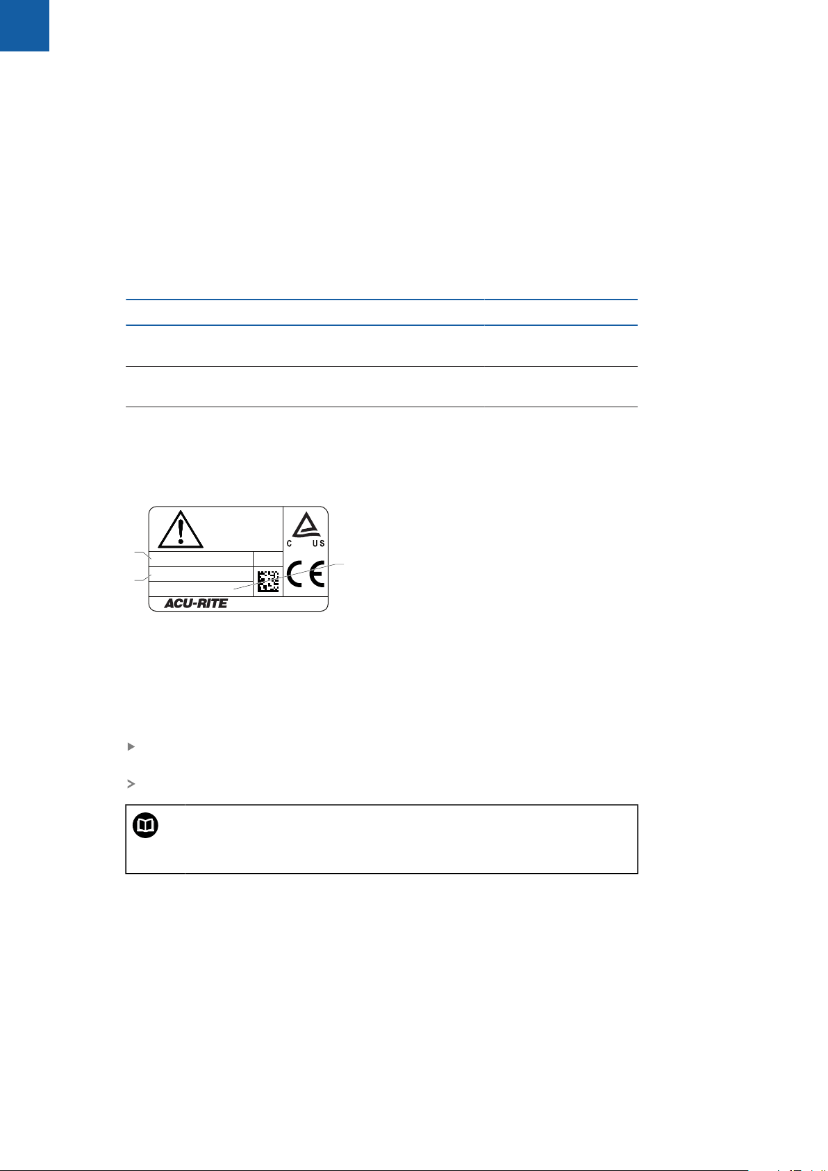
The ID label is provided on the back of the product.
Example:
1
Product designation
2
Part number
3
Index
Validity of the documentation
Before using the documentation and the product, you need to verify that the
documentation matches the product.
Compare the part number and the index indicated in the documentation with
the corresponding data given on the ID label of the product
If the part numbers and indexes match, the documentation is valid
1197250-xx
1197251-xx
1197251-xx
14
If the part numbers and indexes do not match so that the
documentation is not valid, you will find the current documentation for
the product at www.acu-rite.com.
ACU-RITE | DRO 203, DRO 300 | Operating Instructions | 03/2018
Page 15
Fundamentals | Notes on reading the documentation
1.3 Notes on reading the documentation
The table below lists the components of the documentation in the order of priority
for reading.
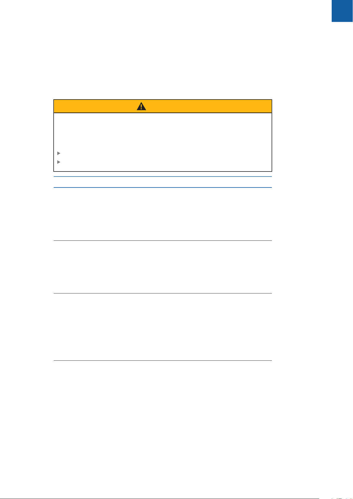
WARNING
Fatal accidents, personal injury or property damage caused by noncompliance with the documentation!
Failure to comply with the documentation may result in fatal accidents, personal
injury or property damage.
Read the documentation carefully from beginning to end
Keep the documentation for future reference
Documentation Description
1
Addendum An addendum supplements or supersedes
the corresponding contents of the Operating
Instructions and, if applicable, of the Installation Instructions. If this document is included in
the shipment, read it first before you proceed.
All other contents of the documentation retain
their validity.
Installation
Instructions
Operating
Instructions
The Installation Instructions contain all the information and safety precautions needed for the
proper mounting and installation of the product.
They are an excerpt from the Operating Instructions and are included in every shipment. This
document has the second highest priority for
reading.
The Operating Instructions contain all the information and safety precautions needed for the
proper operation of the product according to
its intended use. This document has the third
highest priority for reading. This documentation
can be downloaded from the download area
at www.acu-rite.com. The Operating Instruc-
tions must be printed prior to commissioning
the product.
Documentation of connected
measuring devices and other
peripherals
Would you like any changes, or have you found any errors?
We are continuously striving to improve our documentation for you. Please help us
by sending your requests to the following e-mail address:
userdoc@acu-rite.de
ACU-RITE | DRO 203, DRO 300 | Operating Instructions | 03/2018
These documents are not included in delivery.
They are shipped with the respective measuring
devices and peripherals.
15
Page 16

1
Fundamentals | Storage and distribution of the documentation
1.4 Storage and distribution of the documentation
The instructions must be kept in the immediate vicinity of the workplace and must
be available to all personnel at all times. The operating company must inform the
personnel where these instructions are kept. If the instructions have become
illegible, the operating company must obtain a replacement from the manufacturer.
If the product is given or resold to any other party, the following documents must
be passed on to the new owner:
Addendum, if supplied
Installation Instructions
Operating Instructions
1.5 Target group for the instructions
These instructions must be read and observed by every person who performs any
of the following tasks:
Mounting
Installation
Commissioning
Setup, programming and operation
Service, cleaning and maintenance
Troubleshooting
Removal and disposal
16
ACU-RITE | DRO 203, DRO 300 | Operating Instructions | 03/2018
Page 17
Fundamentals | Notes in this documentation
1.6 Notes in this documentation
Safety precautions
Comply with all safety precautions indicated in these instructions and in your
machine tool builder's documentation!
Precautionary statements warn of hazards in handling the product and provide
information on their prevention. Precautionary statements are classified by hazard
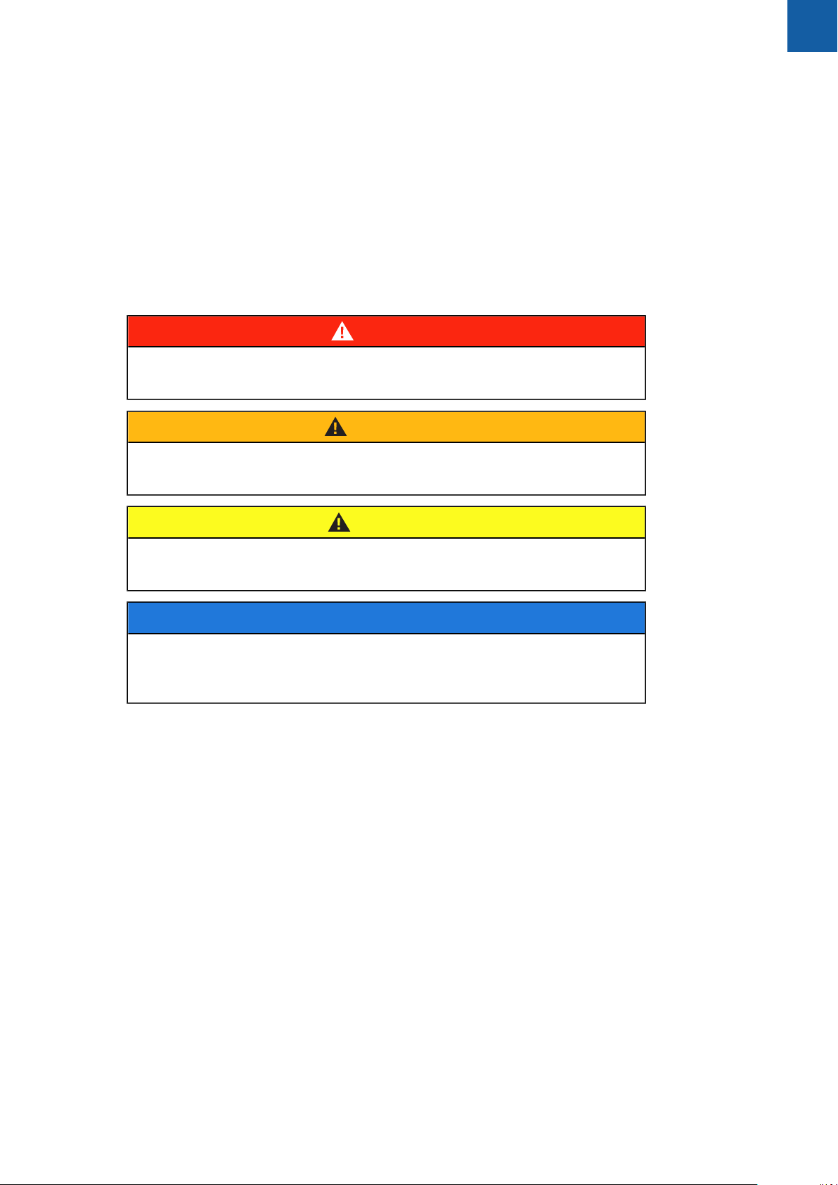
severity and divided into the following groups:
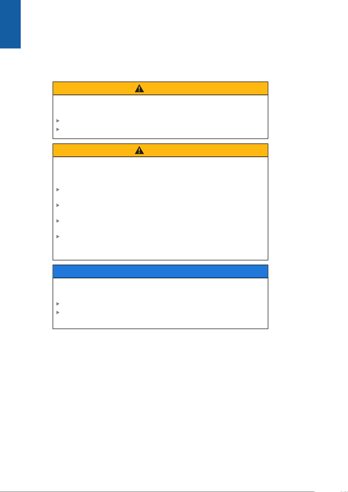
DANGER
Danger indicates hazards for persons. If you do not follow the avoidance
instructions, the hazard will result in death or severe injury.
WARNING
1
Warning indicates hazards for persons. If you do not follow the avoidance
instructions, the hazard could result in death or serious injury.
CAUTION
Caution indicates hazards for persons. If you do not follow the avoidance
instructions, the hazard could result in minor or moderate injury.
NOTICE
Notice indicates danger to material or data. If you do not follow the avoidance
instructions, the hazard could result in things other than personal injury, like
property damage.
ACU-RITE | DRO 203, DRO 300 | Operating Instructions | 03/2018
17
Page 18
1
Fundamentals | Notes in this documentation
Informational notes
Observe the informational notes provided in these instructions to ensure reliable
and efficient operation of the product.
In these instructions, you will find the following informational notes:
The information symbol indicates a tip.
A tip provides important additional or supplementary information.
The gear symbol indicates that the function described depends on the
machine, e.g.
Your machine must feature a certain software or hardware option
The behavior of the function depends on the configurable machine
settings
The book symbol represents a cross reference to external
documentation, e.g. the documentation of your machine tool builder or
other supplier.
18
ACU-RITE | DRO 203, DRO 300 | Operating Instructions | 03/2018
Page 19

Fundamentals | Symbols and fonts used for marking text
1.7 Symbols and fonts used for marking text
In these instructions the following symbols and fonts are used for marking text:
Format Meaning
1
...
...
...
...
Bold Identifies menus, screens, displays, keys, and soft keys
Identifies an action and the result of this action
Example:
Press the enter key
The parameters are saved and the Job Setup menu is
displayed
Identifies an item of a list
Example:
Installation Setup
Job Setup
Example:
Press the Setup soft key
The Configuration Menu is displayed.
ACU-RITE | DRO 203, DRO 300 | Operating Instructions | 03/2018
19
Page 20

Page 21

2
Safety
Page 22

2
Safety | Overview
2.1 Overview
This chapter provides important safety information needed for the proper
mounting, installation and operation of the product.
2.2 General safety precautions
General accepted safety precautions, in particular the applicable precautions
relating to the handling of live electrical equipment, must be followed when
operating the system. Failure to observe these safety precautions may result in
personal injury or damage to the product.
It is understood that safety rules within individual companies vary. If a conflict
exists between the material contained in these instructions and the rules of a
company using this system, the more stringent rules take precedence.
2.3 Intended use
The products of the DRO 203 and DRO 300 series are advanced digital readouts
for use on manually operated machine tools. In combination with linear and angle
encoders,digital readouts of the DRO 203 and DRO 300 series display the position
of the tool in more than one axis and provide further functions for operating the
machine tool.
The products of the DRO 203 and DRO 300 series:
must only be used in commercial applications and in an industrial environment
must be mounted on a suitable stand or holder to ensure the correct and
intended operation of the product
are intended for indoor use in an environment in which the contamination
caused by humidity, dirt, oil and lubricants complies with the requirements of
the specifications
The products of the DRO 203 and DRO 300 series support the use
of a wide variety of peripheral devices from different manufacturers.
HEIDENHAIN cannot make any statements on the intended use of
these devices. The information on their intended use, which is provided
in the associated documentations, must be observed.
2.4 Improper use
When the product is used it must be ensured that no hazard to persons can result.
If any such hazard exists, appropriate measures must be taken by the operating
company.
In particular, the product must not be used in the following applications:
Use and storage outside the specifications
Outdoor use
Use in potentially explosive atmospheres
Use of the product as part of a safety function
22
ACU-RITE | DRO 203, DRO 300 | Operating Instructions | 03/2018
Page 23

Safety | Personnel qualification
2.5 Personnel qualification
The personnel for mounting, installation, operation, service, maintenance and
removal must be appropriately qualified for this work and must have obtained
sufficient information from the documentation supplied with the product and with
the connected peripherals.
The personnel required for the individual activities to be performed on the product
are indicated in the respective sections of these instructions.
The personnel groups that are responsible for mounting, installation, operation,
maintenance and removal have different qualifications and tasks, which are
specified as follows.
Operator
The operator uses and operates the product within the framework specified for the
intended use. He is informed by the operating company about the special tasks
and the potential hazards resulting from incorrect behavior.
2
Qualified personnel
The qualified personnel are trained by the operating company to perform advanced
operation and parameterization. The qualified personnel have the required technical
training, knowledge and experience and know the applicable regulations, and are
thus capable of performing the assigned work regarding the application concerned
and of proactively identifying and avoiding potential risks.
Electrical specialist
The electrical specialist has the required technical training, knowledge and
experience and knows the applicable standards and regulations, and is thus
capable of performing work on electrical systems and of proactively identifying and
avoiding potential risks. Electrical specialists have been specially trained for the
environment they work in.
Electrical specialists must comply with the provisions of the applicable legal
regulations on accident prevention.
ACU-RITE | DRO 203, DRO 300 | Operating Instructions | 03/2018
23
Page 24
2
Safety | Obligations of the operating company
2.6 Obligations of the operating company
The operating company owns or leases the product and the peripherals. It is
responsible that the intended use is complied with at all times.
The operating company must:
Assign the different tasks to be performed on the product to appropriate,
qualified, and authorized personnel
Verifiably train personnel in the tasks they are allowed to perform and how to
perform them
Provide all materials and means necessary in order for personnel to complete
the assigned tasks
Ensure that the product is operated only when in perfect technical condition
Ensure that the product is protected from unauthorized use
2.7 General safety precautions
The safety of any system incorporating the use of this product is the
responsibility of the assembler or installer of the system.
The product supports the use of a wide variety of peripheral devices
from different manufacturers. HEIDENHAIN cannot make any
statements on the specific safety precautions to be taken for
these devices. The safety precautions provided in the respective
documentations must be observed. If no such information has been
supplied, it must be obtained from the manufacturers concerned.
The specific safety precautions required for the individual activities to be
performed on the product are indicated in the respective sections of these
instructions.
24
ACU-RITE | DRO 203, DRO 300 | Operating Instructions | 03/2018
Page 25
Safety | General safety precautions
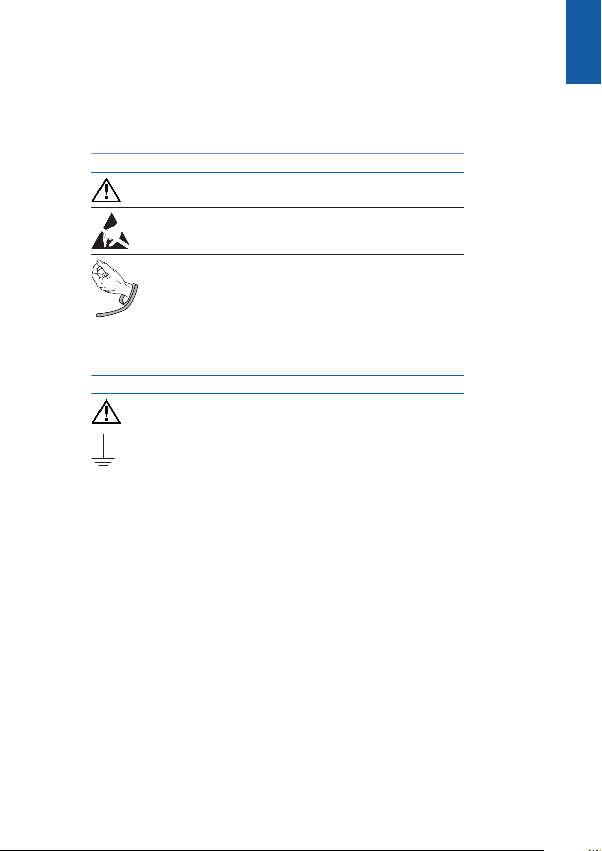
2.7.1 Symbols in the instructions
The following safety symbols are used in this manual:
Symbol Meaning
Identifies information that warns of personal injury
Identifies electrostatic sensitive devices (ESD)
ESD wristband for personal grounding
2
2.7.2 Symbols on the product
The following symbols are used to identify the product:
Symbol Meaning
Observe the safety precautions regarding electricity and power
connection before you connect the product
Earth (ground) terminal as per IEC 60417 - 5017. Observe the
information on installation.
ACU-RITE | DRO 203, DRO 300 | Operating Instructions | 03/2018
25
Page 26
2
Safety | General safety precautions
2.7.3 Electrical safety instructions
WARNING
Hazard of contact with live parts when opening the product.
This may result in electric shock, burns or death.
Never open the housing
Only the manufacturer is permitted to access the inside of the product
WARNING
Hazard of dangerous amount of electricity passing through the human
body upon direct or indirect contact with live electrical parts.
This may result in electric shock, burns or death.
Work on the electrical system and live electrical components is to be
performed only by trained specialists
For power connection and all interface connections, use only cables and
connectors that comply with applicable standards
Have the manufacturer exchange defective electrical components
immediately
Regularly inspect all connected cables and all connections on the product.
Defects, such as loose connections or scorched cables, must be removed
immediately
NOTICE
Damage to internal parts of the product!
Opening the product will result in forfeiture of warranty and guarantee.
Never open the housing
Only the product manufacturer is permitted to access the inside of the
product
26
ACU-RITE | DRO 203, DRO 300 | Operating Instructions | 03/2018
Page 27

3
Transport and
storage
Page 28

3
Transport and storage | Overview
3.1 Overview
This chapter contains all of the information necessary for the transportation and
storage of the product and provides an overview of the items supplied and the
available accessories for the product.
3.2 Unpacking
Open the top lid of the box
Remove the packaging materials
Unpack the contents
Check the delivery for completeness
Check the delivery for damage
3.3 Items supplied and accessories
Items supplied
The following items are included in the shipment:
Product
Power cord (in 1197250-0x, 1197251-0x)
Installation instructions
Addendum (optional)
Further information: "Notes on reading the documentation", Page 15
28
ACU-RITE | DRO 203, DRO 300 | Operating Instructions | 03/2018
Page 29

Transport and storage | Items supplied and accessories
Accessories
The following items are optionally available and can be ordered from HEIDENHAIN
as additional accessories:
Accessories Part number
3
Single-Pos stand
For rigid mounting, inclination angle 20°
Multi-Pos holder
For fastening on an arm, continuously tiltable
and swivelable
Mounting frame
For mounting to a panel
Cover
For protection from dirt and debris
KT 130 edge finder
For probing a workpiece (for setting reference
points). Compatible with DRO 300 products
only.
IOB 610
For switching input and output functions.
Compatible with DRO 300 products only.
Y-cable
For connecting a KT 130 edge finder and an IOB
610. Compatible with DRO 300 products only.
Connecting cable
For connecting a KT 130 edge finder or an IOB
610. Compatible with DRO 300 products only.
1197273-01
1197273-02
1197274-01
1197275-01
283273-xx
1197271-01
1226398-01
1226509-xx
3.4 In case of damage in transit
Have the shipping agent confirm the damage
Keep the packaging materials for inspection
Notify the sender of the damage
Contact the distributor or machine manufacturer for replacement parts
In case of damage in transit:
Keep the packaging materials for inspection
Contact HEIDENHAIN or the machine manufacturer
This applies also if damage occurred to requested replacement parts
during transit.
ACU-RITE | DRO 203, DRO 300 | Operating Instructions | 03/2018
29
Page 30

3
Transport and storage | Repackaging and storage
3.5 Repackaging and storage
Repackage and store the product carefully in accordance with the conditions
stated below.
Repackaging
Repackaging should correspond to the original packaging as closely as possible.
Attach all mounting parts and dust protection caps to the product or repackage
them in the same way they were originally shipped from the factory.
Repackage the product such that it is protected from impact and vibration
during transit
Repackage the product such that it is protected from the ingress of dust or
humidity
Place all accessories that were included in the shipment in the original
packaging
Further information: "Items supplied and accessories", Page 28
Include the Addendum (if it was included in the items supplied), the Installation
Instructions and the Operating Instructions
Further information: "Storage and distribution of the documentation", Page 16
If you return the product for repair to a service agency:
Ship the product without accessories, without measuring devices
and without peripherals
Storage of the product
Package the product as described above
Observe the specified ambient conditions
Inspect the product for damage after any transport or longer storage times
30
ACU-RITE | DRO 203, DRO 300 | Operating Instructions | 03/2018
Page 31

4
Mounting
Page 32

4
10 0
10 0
Mounting | Overview
4.1 Overview
This chapter contains all of the information necessary for mounting the product.
The following steps are only to be performed by qualified personnel.
Further information: "Personnel qualification", Page 23
4.2 Assembly
General mounting information
The receptacle for the mounting variants is provided on the rear panel. The
connection is compatible with VESA standard 100 mm x 100 mm.
The material for attaching the mounting variants on the device is included in the
accessories to the product.
You will also need the following:
Torx T20 screwdriver
2.5 mm allen wrench
7 mm socket wrench
Material for mounting on supporting surface
The product must be mounted on a stand, a holder, or in a mounting
frame to ensure the correct and intended operation of the product.
Routing the cables
In the figures showing the mounting variants, you will find suggestions
for routing the cables after mounting.
When mounting to a mounting variant:
Bring the cables together
Route the cables laterally to the connections as shown in the illustrations
32
ACU-RITE | DRO 203, DRO 300 | Operating Instructions | 03/2018
Page 33

Mounting | Mounting on Single-Pos stand
ID
SN
1234567-xx
DRO 30x
12 345 678 x
www.acu-rite.com
X31
X3
X2
X1
X10
X4
X31
X3
X2
X1
X10
X4
ID
SN
1234567-xx
DRO 30x
12 345 678 x
www.acu-rite.com
ISO 14510-M4x8
Md = 2.6 Nm
124 ±1
180 ±1
21° ±2°
A
22.2
¬4.2
70
A
4.3 Mounting on Single-Pos stand
The Single-Pos stand allows you to place the product on a surface at an inclination
angle of 20° and secure the product to a surface.
Mount the stand to the upper VESA 100 tapped holes on the rear panel of the
product
Use a Torx T20 screwdriver to tighten the countersunk head screws M4 x 8 ISO
14581 included in delivery
Comply with the permissible tightening torque of 2.6 Nm
Secure the product against movement during operation
Attach the supplied self-adhesive rubber pads to the bottom of the product
If you do not screw the product to a surface, attach self-adhesive rubber pads
to the bottom of the stand
Attach the rubber pads to the stand only if you do not screw the
product to a surface.
4
ACU-RITE | DRO 203, DRO 300 | Operating Instructions | 03/2018
DRO 304
Dimensions of the Single-Pos stand
33
Page 34

4
ID
SN
1234567-xx
DRO 30x
12 345 678 x
www.acu-rite.com
ID
SN
1234567-xx
DRO 30x
12 345 678 x
www.acu-rite.com
Mounting | Mounting on Multi-Pos holder
4.4 Mounting on Multi-Pos holder
Mount the holder to the bottom VESA 100 tapped holes on the rear panel of the
product
Use a Torx T20 screwdriver to tighten the countersunk head screws M4 x 10
ISO 14581 (black) included in delivery
Comply with the permissible tightening torque of 2.5 Nm
You can tilt and swivel the holder to an angle that allows you to comfortably view
the readout.
DRO 304
Dimensions of the Multi-Pos holder
34
ACU-RITE | DRO 203, DRO 300 | Operating Instructions | 03/2018
Page 35

Mounting | Mounting in a mounting frame
ID
SN
1234567-xx
DRO 30x
12 345 678 x
www.acu-rite.com
ID
SN
1234567-xx
DRO 30x
12 345 678 x
www.acu-rite.com
209.3
52.8
8.9
ISO 7380-M4x6
Md = 2.6 Nm
ISO 10511-M4
Md = 3.5 Nm
IDSN1234567-xx
DRO 30x
12 345 678 x
www.acu-rite.com
¬4.3
318
338
10
227
247
4.5 Mounting in a mounting frame
The mounting frame allows you to mount the product in a panel.
Mount the rear plate of the frame to the VESA 100 tapped holes on the rear panel
of the product
Use a 2.5 mm allen wrench to tighten the screws M4 x 6 ISO 7380 included in
delivery
Comply with the permissible tightening torque of 2.6 Nm
Mount the rear plate and the product to the front plate of the frame
Use a 7 mm socket wrench to tighten the nuts M4 ISO 10511 included in
delivery
Comply with the permissible tightening torque of 3.5 Nm
Mount the frame and readout in the panel
Refer to the mounting instructions provided with the mounting frame for panel
cutout and mounting information
4
DRO 304
Dimensions of the mounting frame
35
ACU-RITE | DRO 203, DRO 300 | Operating Instructions | 03/2018
Page 36

4
Mounting | Mounting a cover
4.6 Mounting a cover
The cover protects the product from dirt and debris.
Place the cover on the product
Place the cover over the product
Align the cover and product on the right hand side, when viewing the front of
the product
Mount the cover to the product
Remove the adhesive strip protectors from the adhesive tabs
Fold the adhesive tabs toward the product
Press the adhesive tabs against the product securing the tab to the product
36
ACU-RITE | DRO 203, DRO 300 | Operating Instructions | 03/2018
Page 37

5
Installation
Page 38

5
Installation | Overview
5.1 Overview
This chapter contains all the information necessary for installing the product.
The following steps must be performed only by qualified personnel.
Further information: "Personnel qualification", Page 23
5.2 General information
NOTICE
Engaging and disengaging connecting elements!
Risk of damage to internal components.
Do not engage or disengage any connecting elements while the unit is under
power
NOTICE
Electrostatic discharge (ESD)!
This product contains electrostatic sensitive components that can be destroyed
by electrostatic discharge (ESD).
It is essential to observe the safety precautions for handling ESD-sensitive
components
Never touch connector pins without ensuring proper grounding
Wear a grounded ESD wristband when handling product connections
NOTICE
Incorrect pin assignment!
This may cause product malfunctions or damage to the product.
Only assign pins or wires that are used
38
ACU-RITE | DRO 203, DRO 300 | Operating Instructions | 03/2018
Page 39

Installation | Product overview
IDSN1234567-xx
DRO 30x
12 345 678 x
www.acu-rite.com
3
1
2
4
5
5.3 Product overview
The connections on the rear panel of the device are protected by dust protection
caps from contamination and damage.
Contamination or damage may result if the dust protection caps are
missing!
This may impair the proper functioning of the contacts or destroy them.
Remove dust protection caps only when connecting measuring devices or
peripherals
If you remove a measuring device or peripheral, reattach the dust protection
cap to the connection
5
NOTICE
The type and number of connections may vary depending on the
product version.
Rear panel without dust protection caps
DRO 304
Rear panel
1 Power switch and power connection
2 Earth (ground) terminal as per IEC 60471 - 5017
3 X31: USB 2.0 Hi-Speed connection (Type C) for USB mass storage device
(beneath protective cover)
4 X1 to X4: Device variant with 9-pin D-sub connections for encoders with
TTL interface
ACU-RITE | DRO 203, DRO 300 | Operating Instructions | 03/2018
5 X10: 15-pin D-sub connection for touch probes and auxiliary devices (e.g.
HEIDENHAIN touch probe, IOB 610). Available on DRO 300 products only.
39
Page 40

5
Installation | Connecting the encoders
5.4 Connecting the encoders
Remove and save the dust protection caps
Route the cables depending on the mounting variant
Further information: "Assembly", Page 32
Connect the encoder cables tightly to the respective connections
Further information: "Product overview", Page 39
If the cable connectors include mounting screws, do not overtighten them
Pin layout of X1 to X4
TTL
1 2 3 4 5 6 7 8 9
/ U
a1
U
a1
U
a2
5.5 Connecting an accessory
The following accessories can be connected to a DRO 300 product:
HEIDENHAIN KT 130
ACU-RITE IOB 610
Further information: "Accessories", Page 29
A cable is required to connect an accessory to a DRO 300 product.
The following cables are available:
Y-cable
Connecting cable
Further information: "Accessories", Page 29
Remove and save the dust protection caps
Route the cables depending on the mounting variant
Further information: "Assembly", Page 32
Connect one end of the Connecting cable tightly to connection X10 and the
other end to the accessory
or
Connect the single connector end of the Y-cable tightly to connection X10 and
one of the double connector ends to the accessory
U
a2
0 V U
p
U
a0
U
a0
40
Further information: Data sheet provided with the connecting cable or
Y-cable
Further information: "Product overview", Page 39
Do not overtighten the cable connector mounting screws
ACU-RITE | DRO 203, DRO 300 | Operating Instructions | 03/2018
Page 41

Installation | Connecting an accessory
Pin layout of X10
1 2 3 4 5 6 7 8
5
0 V Probe
ready
Signal low / / DC 5 V 0 V 0 V
9 10 11 12 13 14 15
Signal high / / Value
output
contact
5.6 Connecting a USB device
Open the dust protection cap
Connect the USB device to the respective connection
Further information: "Product overview", Page 39
Pin layout of X31
A1 A2 A3 A4 A5 A6 A7 A8 A9 A10 A11 A12
GND TX1 + TX1 - VBUS CC1 D + D - SBU1 VBUS RX2 - RX2 + GND
Probe
input
Value
output
pulse
0 V
B1 B2 B3 B4 B5 B6 B7 B8 B9 B10 B11 B12
GND TX2 + TX2 - VBUS CC2 D + D - SBU2 VBUS RX1 - RX1 + GND
ACU-RITE | DRO 203, DRO 300 | Operating Instructions | 03/2018
41
Page 42

5
Installation | Connecting the line voltage
5.7 Connecting the line voltage
WARNING
Risk of electric shock!
Improper grounding of electrical devices may result in serious personal injury or
death by electric shock.
Always use 3-wire power cables
Make sure the ground wire is correctly connected to the ground of the
building's electrical installations
WARNING
Fire hazard from the use of power cables that do not meet the national
requirements of the respective country in which the product is mounted.
Improper grounding of electrical devices may result in serious personal injury or
death by electric shock.
Use only a power cable that meets at least the national requirements of the
respective country in which the product is mounted
Use a power cable that meets the requirements to connect the power
connection to a 3-wire grounded power outlet
Further information: "Product overview", Page 39
Pin layout of the power connection
1 2 3
L/N N/L
42
ACU-RITE | DRO 203, DRO 300 | Operating Instructions | 03/2018
Page 43

6
Fundamentals of
positioning
Page 44

6
Y
X
Z
I
S
R
Fundamentals of positioning | Overview
6.1 Overview
This chapter describes basic positioning information.
6.2 Datums
The workpiece drawing identifies a certain point on the workpiece (example: “a
corner”) as the absolute datum, and perhaps one, or more other points as relative
datums.
The datum setting procedure establishes these points as the origin of the absolute,
or relative coordinate systems. The workpiece, which is aligned with the machine
axes, is moved to a certain position relative to the tool. The display is set to zero.
6.3 Actual position, nominal position, and Distance-To-Go
The position of the tool at any given moment is called the Actual Position I, while
the position that the tool is to move to is called the Nominal Position S. The
distance from the nominal position to the actual position is called the Distance-ToGo R.
44
ACU-RITE | DRO 203, DRO 300 | Operating Instructions | 03/2018
Page 45

Fundamentals of positioning | Absolute workpiece positions
Y
X
Z
1
20
10
Z=15mm
X=20mm
Y=1
0mm
15
6.4 Absolute workpiece positions
Each position on the workpiece is uniquely identified by its absolute coordinates.
6
Example: Absolute coordinates of position 1:
X = 20 mm
Y = 10 mm
Z = 15 mm
If you are drilling, or milling a workpiece according to a workpiece drawing with
absolute coordinates, the tool is moving to the value of the coordinates.
ACU-RITE | DRO 203, DRO 300 | Operating Instructions | 03/2018
45
Page 46

6
IZ=–15mm
Y
X
Z
2
10
5
5
15
20
10
1
0
I
X=10mm
I
Y=10m
m
3
0
0
Fundamentals of positioning | Incremental workpiece positions
6.5 Incremental workpiece positions
A position can also be referenced to the preceding nominal position. In this case
the relative datum is always the last nominal position. Such coordinates are
referred to as Incremental Coordinates (increment = increase). They are also called
incremental, or chain dimensions, since the positions are defined as a chain of
dimensions. Incremental coordinates are designated with the prefix I.
Example: Incremental coordinates of position 3 referenced to position 2.
Absolute coordinates of position 2:
X = 10 mm
Y = 5 mm
Z = 20 mm
Incremental coordinates of position 3:
IX = 10 mm
IY = 10 mm
IZ = 15 mm
If you are drilling, or milling a workpiece according to a drawing with incremental
coordinates, you are moving the tool by the value of the coordinates.
46
ACU-RITE | DRO 203, DRO 300 | Operating Instructions | 03/2018
Page 47

Fundamentals of positioning | Zero angle reference axis
Y
X
+45°
+180°
–180°
–270°
6.6 Zero angle reference axis
6
The Zero Angle Reference Axis is the 0.0° position. It is defined as one of the two
axes in the plane of rotation. The following table defines the Zero Angle where the
position of the angle is zero for the three possible planes of rotation.
For angular positions, the following reference axes are defined:
Plane Zero Angle Reference Axis
XY +X
YZ +Y
ZX +Z
Positive direction of rotation is counterclockwise if the working plane is viewed in
the negative tool axis direction.
Example: Angle in the working plane X / Y
Plane Zero Angle Reference Axis
+45° ... bisecting line between +X and +Y
+/-180° ... negative X axis
-270° ... positive Y axis
ACU-RITE | DRO 203, DRO 300 | Operating Instructions | 03/2018
47
Page 48

6
Y
X
Z
Fundamentals of positioning | Reading head position
6.7 Reading head position
The reading head position provides feedback to the product that converts the
movement of the machine axes into electrical signals. The product constantly
evaluates these signals, calculates the actual positions of the machine axes, and
displays the positions as a numerical value on the display.
If there is an interruption in power, the calculated position will no longer
correspond to the actual position. When power is restored, you can re-establish
this relationship by using the reference marks on the encoder. This product
provides the Reference Mark Evaluation Feature (REF).
48
ACU-RITE | DRO 203, DRO 300 | Operating Instructions | 03/2018
Page 49

Fundamentals of positioning | Encoder reference marks
6.8 Encoder reference marks
Encoders normally contain one or more reference marks which the Reference
Mark Evaluation feature uses to re-establish datum positions after a power
interruption. There are two main options available for reference marks:
Fixed reference marks
Distance-coded reference marks
Fixed reference marks
6
Encoders that have one or more marks on fixed intervals have to re-establish the
datums correctly. It is necessary to use the same exact reference mark, during
the Reference Mark Evaluation routine, that was used when the datum was first
established.
Position Trac (Distance-coded reference marks)
Encoders that have marks separated by a specific encryption pattern allow the
product to use any two pair of marks along the length of the encoder to reestablish the prior datums. This configuration means that you only have to travel
less than 20 mm anywhere along the encoder to re-establish the datums when the
product is switched back on.
The established datums cannot be restored from one power cycle to
the next if the reference marks were not crossed before the datums
were set.
ACU-RITE | DRO 203, DRO 300 | Operating Instructions | 03/2018
49
Page 50

Page 51

7
Basic operation
Page 52

7
2
1
3
5
4
8
6
7
Basic operation | Overview
7.1 Overview
This chapter describes the product's operating elements and user interface as well
as its basic functions.
7.2 Front panel and keys
1
Display
2
Soft keys
3
Power indicator LED
4
Axis keys
5
Numeric keys
6
Clear key
7
Arrow keys
8
Enter key
Keys Function
Axis Press an axis key to Set or Zero the axis. Refer to the
Status Bar for the current Set/Zero state.
Soft keys
Numeric
Arrow Press the arrow keys to navigate the menus
Enter Press the enter key to confirm a selection and return to the
C Press the C key to clear entries and error messages, or
Soft key labels show milling or turning functions. Press the
corresponding soft key directly below each label to select a
function.
Press a numeric key to enter the corresponding value in a
field
Press the left and right arrow keys to move through the
soft key selectable functions
previous screen
return back to the previous screen
52
ACU-RITE | DRO 203, DRO 300 | Operating Instructions | 03/2018
Page 53

Basic operation | Switch-on/Switch-off
7.3 Switch-on/Switch-off
7.3.1 Switch-on
Before using the product, you need to perform the commissioning
steps. Depending on the purpose of use, you may have to configure
additional setup parameters.
Further information: "Commissioning", Page 65
To switch-on the product:
Turn the power switch on
The power switch is on the rear side of the unit
The unit powers up. This can take a moment.
The first-time configuration screen will appear if this is the first time turning on
the product or after resetting factory default settings
Press the Installation Guide soft key to go to the Installation Guide
or
Press any key to continue to the display
7
7.3.2 Switch-off
To switch-off the product:
Turn the power switch off
The power switch is on the rear side of the unit
The unit powers down
ACU-RITE | DRO 203, DRO 300 | Operating Instructions | 03/2018
53
Page 54

7
10
1
2
3
4
5
6
7
8
9
12
11
7.4 User interface
7.4.1 Display layout
1
Datum
2
Tool
3
Feed rate
4
Stopwatch
5
Unit of measure
6
Operating mode
7
Set/Zero
8
User
9
Soft keys
10
Reference mark indicator
11
Axis labels
12
Graphic positioning aid
Basic operation | User interface
Feature Function
Status bar Displays the current datum, tool, feed rate,
stopwatch time, unit of measure, operating mode
status, set/zero setting, and the current user
Display area Indicates the current position of each axis. Also
shows forms, fields, instruction boxes, error
messages, and help topics
Axis labels Indicates axis for corresponding axis key
Reference mark indicator Indicates current reference mark status
Reference marks are established. A flashing
indicator represents that reference mark detection
is enabled, but the reference marks have not yet
been established.
Reference marks are not established
Soft keys Indicate various functions based on the current
operating mode or menu
Graphic positioning aid Indicates the Distance-To-Go
54
ACU-RITE | DRO 203, DRO 300 | Operating Instructions | 03/2018
Page 55

Basic operation | User interface
7.4.2 Soft keys
There are multiple pages of soft key functions to select when in one of the
operating modes.
To navigate the soft key pages:
Press the left or right arrow key to cursor through each page
Soft key Function
Help Press the Help soft key to open the operating instructions
Tool Press the Tool soft key to open the Tool Table
Abs/Inc Press the Abs/Inc soft key to toggle between Actual Value
Set/Zero Press the Set/Zero soft key to toggle between Set and
Datum Press the Datum soft key to open the Datum form and set
7
(Absolute) and Distance-To-Go (Incremental) modes
Zero functions. Used with individual axis keys.
the datum for each axis
Preset Press the Preset soft key to open the Preset form. This
form is used to set a nominal position. This is a DistanceTo-Go (Incremental) function.
1/2 Press the 1/2 soft key to divide the current position by two.
Available in Mill application only.
Features Press the Features soft key to select the Circle Pattern or
Linear Pattern table
Rad/Dia Press the Rad/Dia soft key to toggle between diameter and
radius measurements. Available in Turn application only.
Setup Press the Setup soft key to access the Configuration menu
Enable Ref Press the Enable Ref soft key when you are ready to identi-
fy a reference mark
Calc Press the Calc soft key to open the calculator
inch/mm Press the inch/mm soft key to toggle between inch and
millimeter units of measure
Disable Ref Press the Disable Ref soft key when you want to cross
over a reference mark and have the system ignore the
reference mark
No Ref Press the No Ref soft key to exit the reference mark evalua-
tion routine and work without reference marks
Program Press the Program soft key to select the program Mode
ACU-RITE | DRO 203, DRO 300 | Operating Instructions | 03/2018
55
Page 56

7
1
2
1
1
7.4.3 Graphic positioning aid
When positioning to the next nominal position, the product assists you by
displaying the Distance-To-Go as well as a graphic positioning aid ("traversing to
zero"). A scale is shown underneath each axis you traverse to zero. The graphic
positioning aid is a small square that symbolizes the axis slide.
1
Graphic positioning aid (axis slide)
2
Distance-To-Go
The positioning aid moves across the scale when the axis slide is within a range
of the nominal position. The default range is ± 5 mm and can be changed in the
Graphic Pos Aid menu.
Further information: "Graphic positioning aid", Page 88
Basic operation | User interface
7.4.4 Operating modes
The product has two operating modes:
Distance-To-Go (Incremental)
Actual Value (Absolute)
Distance-To-Go mode (Incremental)
The Distance-To-Go mode enables you to approach nominal positions by zeroing
the axes and traversing to a position based on its distance from the zeroed
position.
1
Distance-To-Go mode (Inc)
Actual Value mode (Absolute)
The Actual Value mode always displays the current actual position of the tool,
relative to the active datum. In this mode, all moves are done by traveling until the
display matches the nominal position that is required.
56
1
Actual Value mode (Abs)
ACU-RITE | DRO 203, DRO 300 | Operating Instructions | 03/2018
Page 57

Basic operation | User interface
Changing the operating mode
To change the operating mode:
Press the Abs/Inc soft key to toggle between operating modes
7
7.4.5
7.4.6
Stopwatch
On the DRO screen the Stopwatch shows the minutes and seconds until 59:59
is reached, then displays hours and minutes. The Stopwatch shows elapsed time.
The clock starts timing from 0:00.
The Stopwatch can also be operated from the Job Setup menu.
Further information: "Stopwatch", Page 89
Starting and stopping the Stopwatch
To start or stop the Stopwatch:
Press the . (decimal) key on the numeric key pad to start or stop the Stopwatch
The elapsed time field in the status bar shows the total accumulated time
Resetting the Stopwatch
To reset the Stopwatch:
Press the 0 (zero) key on the numeric keypad to reset the Stopwatch time
Calculator
The Calculator is capable of handling everything from simple arithmetic to
complex trigonometry and RPM calculations.
Using the Standard/Trig Calculator
To open the Calculator:
Press the Calc soft key
Press the Standard/Trig soft key
Trig functions contain all trig operators as well as, square and square root.
Whenever you are calculating the SIN, COS, or TAN of an angle, enter the angle
first and then press the appropriate soft key.
When you need to enter more than one calculation into a numeric field, the
calculator will perform multiplication and division before it performs addition and
subtraction.
Ex. If you were to enter 3 + 1 ÷ 8, the calculator will divide one by eight, then add
three for an answer of 3.125.
Angle values use the current angle format selection of decimal degrees,
or radians.
ACU-RITE | DRO 203, DRO 300 | Operating Instructions | 03/2018
57
Page 58

7
Basic operation | User interface
Using the Rpm Calculator
The Rpm Calculator is used to determine the rpm (or surface cutting speed) based
on a specified tool (part, for turning applications) diameter. The values shown are
only an example. Consult your tool manufacturer’s manual to verify spindle speed
ranges per tool.
To use the Rpm Calculator:
Press the Calc soft key
Press the rpm soft key to open the Rpm Calculator form
The Rpm Calculator requires a tool Diameter for Mill applications. The Diameter
value will default to the current tool’s Diameter. If there is no last value entered in
this power cycle, the default value is 0.
Use the numeric key pad to enter a Diameter value
If a Surface Speed value is required, enter the value using the numeric key pad
When a Surface Speed value is entered, the associated rpm value will be
calculated.
Press the Units soft key to show the Units as inch or mm
Press the C key to close the Rpm Calculator and save the current data
7.4.7
Help
Integrated operating instructions provide Help when operating the product.
To open the operating instructions:
Press the Help soft key
If Help has not been opened during the current session the first page of the
operating instructions will be displayed
or
If Help has been opened during the current session the last viewed page of the
operating instructions will be displayed
The following key functions are available in Help:
Key Function
First axis Press the First axis key to open the table of contents
Up arrow Press the Up arrow key to navigate back in the operating
instructions
Down arrow Press the Down arrow key to navigate forward in the
operating instructions
Right arrow Press the Right arrow key to highlight the first link on a
page
If a link is already highlighted:
Press the Right arrow key to highlight the next link on a
page
58
Left arrow Press the Left arrow key to highlight the last link on a page
If a link is already highlighted:
Press the Left arrow key to highlight the previous link on a
page
enter Press the enter key to navigate to a link that is highlighted
C Press the C key to remove a highlight from a link
If no links are highlighted:
Press the C key to exit Help
ACU-RITE | DRO 203, DRO 300 | Operating Instructions | 03/2018
Page 59

Basic operation | User interface
1
7.4.8 Data input forms
Information required for various operational functions and setup parameters are
entered through data input forms. These forms will appear after selecting features
that require additional information. Each form provides specific fields for entering
the required information.
Confirming changes
To confirm changes:
Press the enter key to apply the selected parameter changes
Canceling changes
To cancel changes:
Press the C key to return to the previous screen without saving changes
7.4.9 Reference mark evaluation
The Reference Mark Evaluation feature automatically re-establishes the
relationship between axis slide positions and display values that was last defined
by setting the datum.
The reference mark indicator will flash for each axis with an encoder that has
reference marks. The indicator will stop flashing after crossing over the reference
marks.
7
Activating reference marks
1
Reference marks enabled
To activate reference marks:
Cross over the reference marks for each axis to activate the reference
After a successful reference mark evaluation, the indicator will stop flashing
ACU-RITE | DRO 203, DRO 300 | Operating Instructions | 03/2018
59
Page 60

7
1
Basic operation | User interface
Working without reference marks
The product can also be used without crossing over the reference marks.
1
Reference marks disabled
To work without reference marks:
Press the No Ref soft key to exit the reference mark evaluation routine, and
continue
After disabling reference marks the indicator will have a forward slash through
it, signifying that the reference marks have been disabled
Re-enabling reference marks
Reference marks can be enabled any time after they have been disabled
To re-enable reference marks:
Press the Enable Ref soft key to activate the reference mark evaluation routine
If an encoder is setup without reference marks the reference indicator
will not be displayed. A datum set from the axis will be lost once power
is turned off.
60
ACU-RITE | DRO 203, DRO 300 | Operating Instructions | 03/2018
Page 61

Basic operation | User interface
7.4.10 Selecting a specific reference mark
The product provides the ability to select a specific reference mark on an encoder.
This is important when using encoders with fixed reference marks.
To select a specific reference mark:
Press the Disable Ref soft key
The evaluation routine is paused. Any reference marks that are crossed during
encoder movement are ignored.
Cross over undesired reference marks
Press the Enable Ref soft key
The next reference mark that is crossed will be selected.
Cross the desired reference mark
Repeat this process for all desired reference marks
Press the No Ref soft key to cancel out of routine after all desired axes are
established
Only the axes that are needed require crossing over the reference marks. If all
reference marks have been found the product will return to the DRO display
screen automatically.
7
The product does not store datum points if the reference marks are
not crossed. The relationship between axis slide positions and display
values will not be re-established after a power interruption or switch-off.
7.4.11 Error messages
If an error occurs while working with the product, a message will appear on the
display, and provide an explanation of what caused the error.
Further information: "What to do if...", Page 183
To clear an error message:
Press the C key
The error message will be cleared and normal operation can continue
7.4.12 Setup menus
The product has two menus for setting up operating parameters:
Installation Setup
Job Setup
Installation Setup
The Installation Setup menu is used to establish encoder, display, and
communication parameters.
Further information: "Installation Setup", Page 68
To access the Installation Setup menu:
Press the Setup soft key
Select Installation Setup
The Installation Setup options are displayed
ACU-RITE | DRO 203, DRO 300 | Operating Instructions | 03/2018
61
Page 62

7
Basic operation | User interface
Job Setup
The Job Setup menu is used to accommodate specific machining requirements for
each job.
Further information: "Job Setup", Page 85
To access the Job Setup menu:
Press the Setup soft key
Select Job Setup
The Job Setup options are displayed
7.5
7.5.1
7.5.2
User Management
The User Management menu provides a Supervisor Login and User Job
Settings management.
Supervisor Login
The Supervisor Login allows you to manage users in the User Management menu
and to modify configuration parameters in the Installation Setup menu.
Further information: "Installation Setup", Page 68
To login as a supervisor:
Press the Setup soft key
Open in the sequence:
User Management
Supervisor Login
Enter the Passcode '8891'
Press the enter key
User Job Settings
When Job Setup parameters are configured they are automatically saved under
the selected user.
Further information: "Job Setup", Page 85
62
Selecting a User
To select a User:
Press the Setup soft key
Open in the sequence:
User Management
User Job Settings
Use the up and down arrow keys to highlight Load for the desired User
Press the enter key
The selected User is displayed in the status bar
Press the C key twice to return to the DRO screen
ACU-RITE | DRO 203, DRO 300 | Operating Instructions | 03/2018
Page 63

Basic operation | User Management
Saving User Job Settings
To save User Job Settings:
Select a User
Configure Job Setup parameters for the user
Further information: "Job Setup", Page 85
The Job Setup parameters are automatically saved for the selected user.
Select another User and repeat these steps until all of your required users have
been setup
Supervisor level User Job Settings
A supervisor can create a default set of Job Setup parameters and use the
settings to reset user configurations.
Further information: "Supervisor Login", Page 62
Creating a default set of Job Setup parameters
To create default User Job Settings:
Select User-0
Configure Job Setup parameters for User-0
Further information: "Job Setup", Page 85
The Job Setup parameters are automatically saved for the user
7
Resetting User Job Settings
To reset an individual User:
Select a User
Press the right arrow key to open the drop-down menu
Press the down arrow key to highlight Reset
Press the enter key to select Reset
Press the enter key to reset the Job Setup parameters for the selected user to
the User-0 settings
To reset All Users:
Select All Users
Press the enter key to reset the Job Setup parameters for all users to the
User-0 settings
ACU-RITE | DRO 203, DRO 300 | Operating Instructions | 03/2018
63
Page 64

Page 65

8
Commissioning
Page 66

8
Commissioning | Overview
8.1 Overview
Make sure that you have read and understood the "Basic Operation"
chapter before performing the activities described in this section.
Further information: "Basic operation", Page 51
The following steps are only to be performed by qualified personnel.
Further information: "Personnel qualification", Page 23
During the commissioning process the product is configured for use.
Parameters that are changed during the commissioning process can be reset to
the factory defaults.
Further information: "Factory defaults", Page 79
Backing up the configuration
Configuration data can be backed up after commissioning. The configuration data
can be reused for equivalent products.
Further information: "Configuration parameters", Page 68
66
ACU-RITE | DRO 203, DRO 300 | Operating Instructions | 03/2018
Page 67

Commissioning | Installation Guide
8
8.2
Installation Guide
An Installation Guide is provided the first time you switch-on the product. This
guide will step you through common commissioning parameters.
Information about specific parameters included in the Installation Guide can be
found in the Settings section of these instructions.
Further information: "Settings", Page 165
The Installation Guide provides configuration options for the following
parameters:
Language
Readout Settings
Application
Number of Axes
Encoder Setup
Encoder Type
Encoder
Resolution
Reference Mark
Count Direction
Error Monitor
Display Configuration
Display Resolution
Label
Display Color Scheme
Color Mode
Opening the Installation Guide
To access the Installation Guide from the first-time startup screen:
Press the Installation Guide soft key
The Installation Guide opens
Navigating the Installation Guide
Press the right arrow key to open a parameter drop-down menu
Press the up or down arrow key to highlight a parameter option
Press the enter key to select an option
Press the Next soft key to advance to the next parameter
or
Press the Previous soft key to go back to a previous parameter
Repeat these steps until all parameters have been set
ACU-RITE | DRO 203, DRO 300 | Operating Instructions | 03/2018
67
Page 68

8
Commissioning | Installation Setup
8.3
Installation Setup
Further information: "Settings", Page 165
Installation Setup parameters must be configured only by qualified
personnel.
Further information: "Personnel qualification", Page 23
To access the Installation Setup menu:
Press the Setup soft key
Use the up or down arrow key to highlight Installation Setup
Press the right arrow key
The Installation Setup menu is displayed
8.3.1 File management
Configuration parameters
The configuration of the product can be backed up as a file to make it available
after a reset to the factory default settings or for installation on multiple products.
A file with the following properties needs to be stored on the product for this
purpose:
File format: DAT
File name: config.dat
Importing configuration parameters
To import configuration parameters:
Insert a USB memory device containing the .dat file into the USB connection
Press the Setup soft key
Open in the sequence
Installation Setup
File Management
Configuration Parameters
Press the Import soft key
Press the enter key to initiate importing the configuration parameters
A pop-up warning informs you that the current parameter settings will be
overwritten
Press the enter key to import the configuration parameters and return to the
File Management menu
or
Press the C key to cancel
68
ACU-RITE | DRO 203, DRO 300 | Operating Instructions | 03/2018
Page 69

Commissioning | Installation Setup
Exporting configuration parameters
To export configuration parameters:
Insert a USB memory device into the USB connection
Press the Setup soft key
Open in the sequence
Installation Setup
File Management
Configuration Parameters
Press the Export soft key
Press the enter key to initiate exporting the configuration parameters
A pop-up warning informs you that the current parameter settings will be
exported to the attached USB memory device
The config.dat file on the USB memory device will be overwritten.
8
Press the enter key to export the configuration parameters and return to the
File Management menu
or
Press the C key to cancel
Segmented LEC Table
File format: DAT
File name: slec_1.dat (axis 1), slec_2.dat (axis 2), slec_3.dat (axis 3), slec_4.dat
(axis 4)
Importing a Segmented LEC Table
To import a Segmented LEC Table:
Insert a USB memory device containing the .dat file into the USB connection
Press the Setup soft key
Open in the sequence
Installation Setup
File Management
Segmented LEC Table
Press the Import soft key
Press the enter key to initiate importing the table
A pop-up warning informs you that the current table will be overwritten
Press the enter key to import the table and return to the File Management
menu
or
Press the C key to cancel
ACU-RITE | DRO 203, DRO 300 | Operating Instructions | 03/2018
69
Page 70

8
Commissioning | Installation Setup
Exporting a Segmented LEC Table
To export a Segmented LEC Table:
Insert a USB memory device into the USB connection
Press the Setup soft key
Open in the sequence
Installation Setup
File Management
Segmented LEC Table
Press the Export soft key
Press the enter key to initiate exporting the table
A pop-up warning informs you that the current table will be exported to the
attached USB memory device
Press the enter key to export the table and return to the File Management
menu
or
Press the C key to cancel
Tool Table
File format: DAT
File name: tool_mill.dat (Mill application), tool_turn.dat (Turn application)
Importing a Tool Table
To import a Tool Table:
Insert a USB memory device containing the .dat file into the USB connection
Press the Setup soft key
Open in the sequence
Installation Setup
File Management
Tool Table
Press the Import soft key
Press the enter key to initiate importing the table
A pop-up warning informs you that the current table will be overwritten
Press the enter key to import the table and return to the File Management
menu
or
Press the C key to cancel
70
ACU-RITE | DRO 203, DRO 300 | Operating Instructions | 03/2018
Page 71

Commissioning | Installation Setup
Exporting a Tool Table
To export a Tool Table:
Insert a USB memory device into the USB connection
Press the Setup soft key
Open in the sequence
Installation Setup
File Management
Tool Table
Press the Export soft key
Press the enter key to initiate exporting the table
A pop-up warning informs you that the current table will be exported to the
attached USB memory device
Press the enter key to export the table and return to the File Management
menu
or
Press the C key to cancel
8
ACU-RITE | DRO 203, DRO 300 | Operating Instructions | 03/2018
71
Page 72

8
Commissioning | Installation Setup
Operating Instructions
The product's Operating Instructions can be loaded onto the product and viewed
using the Help function.
Operating Instructions can be loaded to the product in multiple languages. The
product will look for the operating instructions in the Language selected in the Job
Setup menu when loading the file from a USB memory device.
An error will be displayed if the operating instructions are not found on
the USB memory device in the selected Language.
The Operating Instructions can be downloaded from the download area at
www.acu-rite.com.
A file with the following properties needs to be loaded onto the product:
File format: mPub
File name: DRO200_300_xx.mpub
1)
xx: corresponds to the ISO 639-1 two-letter code
To load the Operating Instructions:
Select the desired Language if it is different than the currently selected
language
Further information: "Language", Page 94
Insert a USB memory device containing the Operating Instructions mPub file
into the USB connection
Press the Setup soft key
Open in the sequence
Installation Setup
File Management
Operating Instructions
Press the Load soft key
Press the enter key to initiate loading the Operating Instructions
A pop-up warning informs you that the Operating Instructions will be loaded
Press the enter key to load the Operating Instructions
1)
72
The Operating Instructions can take several minutes to load. Once
the Operating Instructions have loaded the display will return to
the File Management menu.
or
Press the C key to cancel
ACU-RITE | DRO 203, DRO 300 | Operating Instructions | 03/2018
Page 73

Commissioning | Installation Setup
Power-up Screen
You can define an OEM-specific Power-up Screen, e.g. the company name or
logo, which will be displayed when the product is switched on. An image file with
the following properties needs to be stored on the product for this purpose:
File format: 24-Bit Bitmap
Image size: 800 x 480 px
File name: OEM_SplashScreen.bmp
To load a Power-up Screen:
Connect a USB mass storage device containing the Power-up Screen file to
the USB port of the product
Press the Setup soft key
Open in the sequence
Installation Setup
File Management
Power-up Screen
Press the Load soft key
Press the enter key to initiate loading the Power-up Screen
A pop-up warning informs you that the Power-up Screen will be loaded
Press the enter key to load the Power-up Screen and return to the File
Management menu
or
Press the C key to cancel
8
Product Software
To install a Product Software update:
Insert a USB memory device containing the Product Software file into the USB
connection
Press the Setup soft key
Open in the sequence
Installation Setup
File Management
Product Software
Press the Install soft key
Press the enter key to initiate installing the software update
A pop-up warning informs you that the software update will be installed
Press the enter key to install the software update
The product will restart
or
Press the C key to cancel
ACU-RITE | DRO 203, DRO 300 | Operating Instructions | 03/2018
73
Page 74

8
Commissioning | Installation Setup
8.3.2
Encoder Setup
Encoder Setup parameters are used to configure each encoder input.
The adjustment procedure is the same for each axis. The following
section describes the configuration of one axis. Repeat the procedure
for each axis.
To set up an encoder:
Press the Setup soft key
Open in the sequence
Installation Setup
Encoder Setup
Select the encoder to set up:
X1
X2
X3
X4
The Encoder Setup parameters are displayed for the selected axis
Select the Encoder Type:
Linear
Rotary
Rotary (Linear): a rotary encoder connected to a leadscrew
Press the µm/inch soft key to select the desired Resolution unit of measure
µm
inch
Select the desired Resolution:
The Resolution can also be established by moving the axis in either
direction.
Press the enter key to confirm the selection
Select the desired Reference Mark type:
None: no reference signal
Single: single reference mark
Position Trac: an encoder with the Position-Trac feature
P-Trac (ENC 250): an ENC 250 encoder with the Position-Trac feature
EverTrack: an encoder with the EverTrack feature
LMF: an LMF encoder with reference marks
Press the enter key to confirm the selection
Select the desired Count Direction:
Negative
Positive
When the encoder’s count direction matches the operators count direction,
select Positive. When they do not match, select Negative.
The Count Direction can also be established by moving the axis in
the positive direction.
74
ACU-RITE | DRO 203, DRO 300 | Operating Instructions | 03/2018
Page 75

Commissioning | Installation Setup
Press the enter key to confirm the selection
Select On or Off in the Error Monitor parameter to enable or disable monitoring
of counting errors
Press the enter key to confirm the selection
Press the enter key to save the Encoder Setup parameter changes and return
to the Installation Setup menu
or
Press the C key to cancel
8
ACU-RITE | DRO 203, DRO 300 | Operating Instructions | 03/2018
75
Page 76

8
Commissioning | Installation Setup
8.3.3
Display Configuration
Display Configuration parameters are used to configure the way axes information
is shown on the display.
The adjustment procedure is the same for each axis display. The
following section describes the configuration of one axis display. Repeat
the procedure for each axis display.
To configure an axis display:
Press the Setup soft key
Open in the sequence
Installation Setup
Display Configuration
Select the axis display to set up:
Display 1
Display 2
Display 3
Display 4
The Display Configuration parameters are displayed for the selected axis
display
Select the desired Display Resolution
Display Resolution options vary based on the encoders connected to the product.
Press the enter key to confirm the selection
Select a Label for the axis display or Off to turn off the selected axis display:
Off
X
Y
Z
U
V
W
A
B
C
S
76
Press the enter key to confirm the selection
Select Off or On to enable or disable a Subscript zero being displayed after the
axis label
Press the enter key to confirm the selection
Select the desired input for the axis display in the Input 1 parameter:
X1
X2
X3
X4
Press the enter key to confirm the selection
Select + or - in the Couple Operation parameter to couple a second input with
the first:
+
-
Off
Press the enter key to confirm the selection
Select the desired input to couple with Input 1 in the Input 2 parameter:
ACU-RITE | DRO 203, DRO 300 | Operating Instructions | 03/2018
Page 77

Commissioning | Installation Setup
Not Defined
X1
X2
X3
X4
Press the enter key to confirm the selection
Press the enter key to save the Display Configuration parameter changes and
return to the Installation Setup menu
or
Press the C key to cancel
8
8.3.4
Readout Settings
Readout Settings parameters are used to set Application, axes, and Position
Recall requirements.
To configure the readout:
Press the Setup soft key
Open in the sequence
Installation Setup
Readout Settings
Select the Application
Mill
Turn
Select the Number of Axes:
1
2
3
4
Press the enter key to confirm the selection
Select On or Off to enable or disable Position Recall
Position Recall will store the last position of each axis when power was turned
off, and then redisplay that position once power is turned back on.
Any movement that occurs while power is off will be lost.
Whenever power has been off it is recommended to re-establish
workpiece datums using the reference mark evaluation procedure.
Further information: "Reference mark evaluation", Page 59
Press the enter key to confirm the selection
Press the enter key to save the Readout Settings parameter changes and
return to the Installation Setup menu
or
Press the C key to cancel
ACU-RITE | DRO 203, DRO 300 | Operating Instructions | 03/2018
77
Page 78

8
Commissioning | Installation Setup
8.3.5
8.3.6
Diagnostics
The Diagnostics feature provides a way to test the keypad and display.
Press the Setup soft key
Open in the sequence
Installation Setup
Diagnostics
Keypad Test
An image of the keypad provides an indication when a key is pressed and released.
To test the keypad:
Press each key to test
A key that is operating properly will turn green in the Diagnostics screen when
pressed on the keypad, and change to gray when released.
Press the C key two times to exit the keypad test
Display Test
To test the display:
Press the enter key to cycle through the available colors
Display Color Scheme
Display Color Scheme parameters are used to set the Color Mode of the product.
Select the Color Mode that makes the display easiest to view in your workspace
lighting conditions.
To select a color scheme:
Press the Setup soft key
Open in the sequence
Installation Setup
Display Color Scheme
Select the Color Mode:
Day: the color scheme is set to Day and cannot be selected by the user
Night: the color scheme is set to Night and cannot be selected by the user
User Selectable: the color mode can be selected by the user from the Job
Setup menu
Press the enter key to confirm the selection
Press the enter key to save the Display Color Scheme parameter changes and
return to the Installation Setup menu
or
Press the C key to cancel
78
ACU-RITE | DRO 203, DRO 300 | Operating Instructions | 03/2018
Page 79

Commissioning | Installation Setup
8.3.7 Factory defaults
Parameter changes made in the Job Setup and Installation Setup menus can be
reset to the factory default settings. All parameters will be reset.
Further information: "Settings", Page 165
To reset parameters to factory default settings:
Press the Setup soft key
Open in the sequence
Installation Setup
Factory Defaults
Reset Settings
Press the Yes/No soft key and select Yes
Press the enter key to initiate resetting the product to the factory default
settings
A warning window will appear to confirm the reset
Press the enter key to reset parameters to the factory default settings
The product will restart.
or
Press the C key to cancel the reset
8
8.3.8
Error Compensation
The distance a cutting tool travels, measured by an encoder, can in certain cases
differ from the actual tool travel. This error can occur due to ball screw pitch
error, or deflection and tilting of axes. Errors can be determined with a reference
measurement system, such as gauge blocks.
The product provides the ability to compensate for linear errors, and each axis can
be programmed separately with the appropriate compensation.
Error compensation is only available when using linear encoders.
The adjustment procedure is the same for each axis. The following
section describes the configuration of one axis. Repeat the procedure
for each axis.
ACU-RITE | DRO 203, DRO 300 | Operating Instructions | 03/2018
79
Page 80

8
Commissioning | Installation Setup
Configuring Linear Error Compensation
Linear Error Compensation (LEC) can be applied, if the results of a comparison
with a reference standard show a linear deviation over the whole measuring
length. In this case the error can be compensated by the calculation of a single
correction factor.
To calculate the correction factor use this formula:
Correction factor LEC = ((S – M) / M) x 106 ppm with:
S = measured length with a reference standard
M = measured length with device at axis
Example:
If the length of the standard you used is 500 mm, and the measured length along
the X-axis is 499.95, then the LEC for the X-axis is 100 parts per million (ppm).
LEC = ((500 – 499.95) / 499.95) x 106 ppm = 100 ppm (rounded to the nearest
whole number).
To configure LEC:
Press the Setup soft key
Open in the sequence
Installation Setup
Error Compensation
Select the input to configure:
X1
X2
X3
X4
Enter the compensation factor using the numeric keypad
Repeat these steps for each axis you want to configure
Press the enter key to save the Error Compensation parameter changes and
return to the Installation Setup menu
or
Press the C key to cancel
80
ACU-RITE | DRO 203, DRO 300 | Operating Instructions | 03/2018
Page 81

Commissioning | Installation Setup
Configuring LEC automatically
The correction factor may be calculated automatically using a standard gauge
block.
To configure LEC automatically:
Press the Setup soft key
Open in the sequence
Installation Setup
Error Compensation
Select the input to configure:
X1
X2
X3
Select Linear to configure LEC for the input
Press the enter key to confirm the selection
Press the Auto Calc soft key to begin teaching the LEC factor
Touch one edge of the standard with the tool
Press the Teach Edge 1 soft key
Touch the opposite edge of the standard with the tool
Press the Teach Edge 2 soft key
Enter the length of the standard in the Actual field
Press the enter key to confirm the entered value
Repeat these steps for each axis you want to configure with linear error
compensation
Press the enter key to save the Error Compensation parameter changes and
return to the Installation Setup menu
or
Press the C key to cancel
8
Configuring Segmented LEC
Segmented LEC should be applied if the results of the comparison with a
reference standard show an alternating, or oscillating deviation. The required
correction values are calculated, and entered in a table. The product supports up
to 200 points per axis. The error value between two entered adjacent correction
points is calculated with linear interpolation.
Segmented LEC is only available on scales with reference marks. If
Segmented LEC has been defined, no error compensation will be
applied until the reference marks have been crossed.
ACU-RITE | DRO 203, DRO 300 | Operating Instructions | 03/2018
81
Page 82

8
Commissioning | Installation Setup
Segmented LEC setup
The encoder has an inherent count direction. This may not reflect the user defined
count direction and is only required for determining Segmented LEC.
Single reference mark encoders must cross the same reference mark
each time the product is powered on.
To establish the inherent count direction for any installed encoder on a given axis,
complete the following:
Press the Setup soft key
Open in the sequence
Installation Setup
Encoder Setup
Select the input to configure:
X1
X2
X3
Select Count Direction
Press the Positive/Negative soft key and select Positive
Press the enter key to confirm the entered value
Press the enter key to save the parameter changes
Press the C key three times to return to the main display
Move the axis that the encoder is mounted on and note the direction of
movement required for the positive direction
The encoder’s inherent count direction is now established.
82
ACU-RITE | DRO 203, DRO 300 | Operating Instructions | 03/2018
Page 83

Commissioning | Installation Setup
Starting a Segmented LEC table
To start a Segmented LEC table:
Press the Setup soft key
Open in the sequence
Installation Setup
Error Compensation
Select the input to configure:
X1
X2
X3
Select Segmented to configure Segmented LEC for the input
Press the enter key to confirm the selection
Press the Create Table soft key to begin creating the table
All correction points (up to 200) are equally spaced from the start point.
Enter the Number of points
Press the down arrow key
Enter the Spacing of Points
Press the down arrow key
The start point is measured from the encoder’s reference point.
If this distance is known:
Enter the Start Point distance
or
If this distance is not known:
Move to the location of the start point
Press the Teach soft key
Press the enter key to confirm the entered values
A pop-up warning informs you that creating a new table will clear any existing
error points
Press the enter key to save the table and return to the Error Compensation
menu
Repeat these steps for each axis you want to create a Segmented LEC table
8
Configuring a Segmented LEC table
Press the Edit Table soft key to view the table entries
Press the up or down arrow keys or the numeric keys to move to the
correction point to be added or changed
Press the right arrow key
Enter the known deviation which exists at this point
Press the enter key
Repeat these steps for each point that requires a correction point
Press the enter key to exit the table and return to the Error Compensation
menu
ACU-RITE | DRO 203, DRO 300 | Operating Instructions | 03/2018
83
Page 84

8
Commissioning | Installation Setup
8.3.9 Backlash compensation
When using a rotary encoder with a lead screw, a change in direction of the
table might cause an error in the displayed position due to clearances within the
lead screw assembly. This clearance is referred to as backlash. This error can be
compensated for by inputting the amount of backlash within the lead screw into
the Backlash Compensation feature.
If the rotary encoder is ahead of the table (displayed value is greater than the
table’s true position), this is called positive backlash, and the value entered should
be the positive value of the amount of error.
No Backlash Compensation is 0.000.
To specify backlash compensation:
Press the Setup soft key
Open in the sequence
Installation Setup
Backlash Comp.
Select the input to configure:
X1
X2
X3
X4
Press the On/Off soft key and select On
Enter the backlash compensation value
Repeat these steps for all axes that require backlash compensation
Press the enter key to save the backlash compensation values and return to the
Installation Setup menu
or
Press the C key to cancel
8.3.10 Spindle settings
This feature is available on DRO 300 products only.
Spindle Settings options are available when an IOB 610 is connected to a DRO
300 product. Refer to the IOB 610 operation section for configuration information.
Further information: "Spindle Speed control", Page 147
8.3.11 Switching outputs
This feature is available on DRO 300 products only.
Switching Outputs options are available when an IOB 610 is connected to a DRO
300 product. Refer to the IOB 610 operation section for configuration information.
Further information: "Output settings", Page 145
84
ACU-RITE | DRO 203, DRO 300 | Operating Instructions | 03/2018
Page 85

Commissioning | Installation Setup
8.3.12 CSS settings
This feature is available on DRO 300 products only.
CSS Settings options are available when an IOB 610 is connected to a DRO 300
product. Refer to the IOB 610 operation section for configuration information.
Further information: "CSS control settings", Page 157
8.4 Job Setup
The Job Setup menu is used to establish specific machining requirements for each
job.
8
8.4.1
Units
Units parameters are used to specify the preferred display units and format.
You can also select the unit of measure by pressing the inch/mm key in either
operating mode.
To set the unit of measure:
Press the Setup soft key
Open in the sequence
Job Setup
Units
Select the Linear units of measure:
inch
mm
Press the enter key to confirm the selection
Select the Angular units of measure:
Decimal Degrees
Radians
DMS: Degrees, Minutes, Seconds
Press the enter key to confirm the selection
Press the enter key to save the Units parameter changes and return to the Job
Setup menu
or
Press the C key to cancel
ACU-RITE | DRO 203, DRO 300 | Operating Instructions | 03/2018
85
Page 86

8
Commissioning | Job Setup
8.4.2
Scale Factor
Scale Factor is used to scale a part up or down. A scale factor of 1.0 creates a part
with the exact size as dimensioned on a print. A scale factor >1 “grows” the part,
and <1 “shrinks” the part.
The Scale Factor setting range is ±0.100 to 100.000
Settings are retained on a power cycle.
When the Scale Factor is a value other than 1, the scaling symbol is shown on
the axis display.
To set a Scale Factor:
Press the Setup soft key
Open in the sequence
Job Setup
Scale Factor
Select the axis to configure
Press the On/Off soft key and select On
Enter the Scale Factor value
Repeat these steps for all axes that require a Scale Factor
Press the enter key to save the values and return to the Job Setup menu
or
Press the C key to cancel
Mirroring a part
A Scale Factor of -1.00 will produce a mirror image of the part. You can both mirror
and scale a part at the same time.
86
ACU-RITE | DRO 203, DRO 300 | Operating Instructions | 03/2018
Page 87

Commissioning | Job Setup
8
8.4.3
Edge Finder
This feature is available on DRO 300 products only.
Edge Finder parameters are used to setup the KT-130 edge finder.
Diameter and Length Offset values are in the Units selected in the form.
To set up an Edge Finder:
Press the Setup soft key
Open in the sequence
Job Setup
Edge Finder
Enter the Diameter using the numeric keypad
Enter the Length Offset using the numeric keypad
Select the Units:
inch
mm
Press the enter key to confirm the selection
Press the enter key to save the Edge Finder parameter changes and return to
the Job Setup menu
or
Press the C key to cancel
8.4.4
Diameter Axes
Diameter Axes parameters are used to set which axes can display radius or
diameter values.
To setup the display of radius or diameter values:
Press the Setup soft key
Open in the sequence
Job Setup
Diameter Axes
Select the desired axis to setup
Press the On/Off soft key and select On to enable the display of radius or
diameter values for the selected axis
Repeat these steps for each axis to enable
Press the enter key to save the Diameter Axes parameter changes and return
to the Job Setup menu
or
Press the C key to cancel
ACU-RITE | DRO 203, DRO 300 | Operating Instructions | 03/2018
87
Page 88

8
Commissioning | Job Setup
8.4.5
Measured Value Output
This feature is available on DRO 300 products only.
Measured Value Output is used to enable data output during probing operations.
When Data Output Probing is enabled, measurement data is output when a probe
operation is completed. Probe measurement values, while doing probe operations
within the set datum function, can be sent over the USB port to a USB mass
storage device.
To enable Measured Value Output:
Press the Setup soft key
Open in the sequence
Job Setup
Measured Value Output
Press the On/Off soft key to enable Data Output Probing
Press the enter key to save the Measured Value Output parameter changes
and return to the Job Setup menu
or
Press the C key to cancel
8.4.6 Graphic positioning aid
Graphic positioning aids are displayed below each axis in Distance-To-Go (Inc)
mode. Each axis has its own range that can be set.
Further information: "Graphic positioning aid", Page 56
To configure graphic positioning aid settings:
Press the Setup soft key
Open in the sequence
Job Setup
Graphic Pos Aid
Select the desired axis to setup
The default range setting is 5.000 mm.
Press the On/Off soft key to select On and use the default range setting
or
Enter a range setting using the numeric keypad
Repeat the process for each axis you would like to set
Press the enter key to save the Graphic Pos Aid parameter changes and return
to the Job Setup menu
or
Press the C key to cancel
88
ACU-RITE | DRO 203, DRO 300 | Operating Instructions | 03/2018
Page 89

Commissioning | Job Setup
8
8.4.7
8.4.8
Status Bar Settings
The Status Bar is the segmented bar at the side of the display that shows the
current Datum, Tool, Feed Rate, Stopwatch time, Units, operating mode status,
Set/Zero setting, and the Current User.
To configure the status bar settings:
Press the Setup soft key
Open in the sequence
Job Setup
Status Bar Settings
Select a parameter
Press the On/Off soft key to enable or disable the selected option from being
displayed in the status bar
Repeat for each option you would like to enable or disable
Press the enter key to save the Status Bar Settings parameter changes and
return to the Job Setup menu
or
Press the C key to cancel
Stopwatch
The Stopwatch shows the hours, minutes, and seconds elapsed time. The clock
starts timing from 00:00:00.
The Stopwatch can also be operated in the DRO screen using the numeric keypad.
Further information: "Stopwatch", Page 57
Accessing the Stopwatch controls
To access the controls:
Press the Setup soft key
Open in the sequence
Job Setup
Stopwatch
Starting and stopping the Stopwatch
To start or stop the Stopwatch:
Press the Start/Stop soft key to start or stop the Stopwatch
The Elapsed Time field shows the total accumulated time
Resetting the stopwatch
To reset the Stopwatch:
Press the Reset soft key to reset the stopwatch time
ACU-RITE | DRO 203, DRO 300 | Operating Instructions | 03/2018
89
Page 90

8
Commissioning | Job Setup
8.4.9
Skew Compensation for Mill applications
This feature is available on DRO 300 products only.
Skew Compensation allows you to drill holes on a workpiece without aligning the
workpiece on the machine. Use this feature only for drilling holes.
When skew compensation is activated, the skew icon S is displayed on the right
side of the axis display.
To configure Skew Compensation:
Press the Setup soft key
Open in the sequence
Job Setup
Skew Compensation
Press the On/Off soft key to enable Skew Compensation
Highlight the Angle field
Enter the skew angle using the numeric keypad if it is known
or
The skew angle is learned by touching off two points along one
side. When using the edge finder, the location of the edge is
captured automatically.
Touch a point on an edge with an edge finder, or touch a point and press the
Teach soft key if probing with a tool
Touch a second point on the same edge with an edge finder, or touch a second
point and press the Teach soft key if probing with a tool
90
ACU-RITE | DRO 203, DRO 300 | Operating Instructions | 03/2018
Page 91

Commissioning | Job Setup
8
8.4.10
Remote Switch
This feature is available on DRO 300 products only.
The remote switch sets the parameters so the external switch (pendant, or foot
switch) can be enabled to perform any or all of the following functions:
Data Output: send position information over the USB port to a USB mass
storage device when the switch is closed
Zero: zero an axis when the switch is closed
Next: advance to the next hole in a hole pattern or next step in a program when
the switch is closed
To setup the Remote Switch:
Press the Setup soft key
Open in the sequence
Job Setup
Remote Switch
Press the On/Off soft key and select On, to enable Data Output
Highlight the Zero field
Press an axis key to enable zeroing of the axis when the switch is closed. More
than one axis can be selected.
Highlight the Next field
Press the On/Off soft key and select On, to enable advancing to the next hole
in a hole pattern or next step in a program when the switch is closed
Press the enter key to save the Remote Switch parameter changes and return
to the Job Setup menu
or
Press the C key to cancel
ACU-RITE | DRO 203, DRO 300 | Operating Instructions | 03/2018
91
Page 92

8
Commissioning | Job Setup
8.4.11
DRO View Settings
This feature is available on DRO 300 products only.
The product has the ability to define up to three DRO display configurations
(views). Each view defines which axes displays appear on the screen when the
view is selected.
With three views available, one may be set to all available axes, and the others
may be a subset of the axes.
Axis keys correspond to the axes being displayed in the current DRO
view. If only two axes are being displayed, and there are more axis keys
(3 or 4), then only the top two keys will function. Unmatched keys are
ignored.
When two or more DRO views are configured, the DRO mode includes a View
soft key which is used to toggle between DRO 1, DRO 2, and DRO 3 views. The
current view is indicated on the soft key.
Multiple DRO views are only available when the full screen DRO is displayed. In
screens where the small DRO is displayed, all axes positions are displayed and
multiple DRO views are not available.
When running a program or a single cycle pattern, the large DRO uses the current
DRO view that is selected. The view with the graphic and small DRO will show all
available axes.
To setup the DRO View Settings:
Press the Setup soft key
Open in the sequence
Job Setup
DRO View Settings
Highlight the DRO view field you would like to configure
DRO 1
DRO 2
DRO 3
Press an axis key to add the axis to the selected view. If an axis key is pressed
for an axis that is already included, the axis will be removed.
Repeat the last two steps for all views you would like to configure
Press the enter key to save the DRO View Settings parameter changes and
return to the Job Setup menu
or
Press the C key to cancel
92
ACU-RITE | DRO 203, DRO 300 | Operating Instructions | 03/2018
Page 93

Commissioning | Job Setup
8
8.4.12
Display Settings
Display Settings parameters are used to adjust the appearance of the display.
To configure Display Settings:
Press the Setup soft key
Open in the sequence
Job Setup
Display Settings
Use the left or right arrow key to adjust the Brightness level of the display
The display brightness can also be adjusted using the up and down arrow keys
when the product is in either operating mode.
Select the time in minutes that the display is idle before the Display Saver
(min) is activated and the display is switched off:
Off
10
30
Press the enter key to confirm the selection
Press the Day/Night soft key to select the desired Color Mode:
Night
Day
Select how the axis that is in motion is displayed:
Normal: All axes are displayed normal
Dynamic Zoom: The axis in motion is displayed larger than axes not in
motion
Highlight: In Day mode axes in motion are displayed in black, axes not in
motion are displayed in gray. In Night mode axes in motion are displayed in
white, axes not in motion are displayed in gray.
Press the enter key to confirm the selection
Press the enter key to save the Display Settings parameter changes and return
to the Job Setup menu
or
Press the C key to cancel
ACU-RITE | DRO 203, DRO 300 | Operating Instructions | 03/2018
93
Page 94

8
Commissioning | Job Setup
8.4.13
8.4.14
System Information
The System Information screen provides product and software information.
Available information:
Product Name
Product ID
Serial Number
Software Version
Bootloader Version
FPGA Version
Board ID
To access System Information:
Press the Setup soft key
Open in the sequence
Job Setup
System Information
Press the enter key
The System Information screen is displayed
Press the C key to exit System Information
Language
The Language parameter is used to select the language for the user interface. The
default language is English.
To change the Language:
Press the Setup soft key
Open in the sequence
Job Setup
Language
Select the desired language
Press the enter key to confirm the selection
Press the enter key to save the Language parameter change and return to the
Job Setup menu
or
Press the C key to cancel
94
ACU-RITE | DRO 203, DRO 300 | Operating Instructions | 03/2018
Page 95

9
Milling specific
operations
Page 96

9
Y
X
2
1
Z
M
X=50
Milling specific operations | Overview
9.1 Overview
This chapter describes operations and soft key functions specific to milling
applications.
Make sure that you have read and understood the "Basic Operation"
chapter before performing the activities described in this section.
Further information: "Basic operation", Page 51
9.2
1/2 soft key
The 1/2 soft key is available when the product is setup for milling applications and
is used to find the centerline (or midpoint) between two locations along a selected
axis of a workpiece. This can be performed in either Actual Value or Distance-To-Go
mode.
This feature will change datum locations when in Actual Value mode.
Example: Finding the midpoint along a selected axis
96
X dimension: X = 100 mm
Midpoint: 50 mm
To find the midpoint:
Move the tool to the first point
The Set/Zero soft key must be set to Zero.
Press the X axis key
Move to the second point
Press the 1/2 soft key
Press the X axis key
Move the tool until zero is reached
This is the midpoint location
ACU-RITE | DRO 203, DRO 300 | Operating Instructions | 03/2018
Page 97

Milling specific operations | Tool Table
9
9.3
Tool Table
The Tool Table is used to store diameter and length offset information for tools.
The DRO 203 Tool Table can store information for up to 16 tools.
The DRO 300 Tool Table can store information for up to 100 tools.
Opening the Tool Table
To open the Tool Table:
Press the Tool soft key
Selecting a Tool
To select a Tool:
Use the up or down arrow key to highlight a tool
or
Enter the tool number using the numeric key pad
Press the right arrow key
or
Press the enter key
The tool form for the selected tool is displayed
9.3.1 Soft keys
The following soft keys are available in the Tool Table form or in the individual tool
data form:
Soft key Function
Tool Axis Press the Tool Axis soft key to toggle and select which
axis the tool length offsets will affect. The tool’s diameter
values will subsequently be used to offset the remaining
two axes.
Teach Press the Teach soft key to automatically enter the tool
offset length. This key is only available in the Length field.
Clear Press the Clear soft key to remove a tool from the table
Use Press the Use soft key to select the highlighted tool from
the table
Help Press the Help soft key to access Tool Table specific help
9.3.2 Importing and exporting
A Tool Table can be imported from an existing file or exported for backup and
future use.
Further information: "Tool Table", Page 70
ACU-RITE | DRO 203, DRO 300 | Operating Instructions | 03/2018
97
Page 98

9
R–
R+
Y
X
R
0
Z
X
∆L3<0
∆L
2
>0
∆L
1
=0
D
1
T
1
T
2
T
3
D
2
D
3
Milling specific operations | Tool Table
9.3.3 Tool compensation
Tool compensation allows you to enter workpiece dimensions directly from the
drawing.
Radius compensation
Tool radius compensation is calculated based on the value entered in the Diameter
field in the Tool form.
R represents the tool radius. The displayed distance-to-go is automatically
lengthened R+, or shortened R- by the value of the tool radius.
Further information: "Presetting a target position", Page 108
Length offset
Tool length offset is calculated based on the value entered into the Length field in
the Tool form. The length offset can be entered as a known value or the product
can teach the offset.
Further information: "Entering tool data", Page 99
The tool length is the difference in length ΔL between the tool and the reference
tool. The length difference is indicated with the “Δ” symbol. The reference tool is
indicated by T1.
If the tool is longer than the reference tool: ΔL > 0 (+)
If the tool is shorter than the reference tool:ΔL < 0 (–)
98
ACU-RITE | DRO 203, DRO 300 | Operating Instructions | 03/2018
Page 99

Milling specific operations | Tool Table
9.3.4 Entering tool data
To enter data into a Tool form:
Press the Tool soft key
Use the up or down arrow key to highlight the desired tool
or
Enter the tool number using the numeric keypad
Press the Enter key
The Tool form for the selected tool is displayed
Enter the tool Diameter
Enter the tool Length
or
Press the Teach soft key and follow the procedure for Teaching length offset
described in this section.
Select the tool Units
inch
mm
Select the tool Type
Not Defined
Ball End Mill
Boring Head
Broach
Carbide Mill
Counter Bore
Counter Sink
Drill
Engraving Tip
Flat End Mill
Fly Cutter
Pilot Drill
9
Reamer
Roughing Mill
Shell End Mill
Special Mill
Tap
Spindle data is required when Spindle Speed control has been installed. Available
on the DRO 300 only.
Further information: "Spindle Speed control operation", Page 151
Press the enter key to save the tool changes and return to the Tool Table
ACU-RITE | DRO 203, DRO 300 | Operating Instructions | 03/2018
99
Page 100

9
Milling specific operations | Tool Table
Teaching length offset
It is also possible to have the product determine an offset. This method involves
touching the tip of each tool to a common reference surface. This allows the
product to determine the difference between the length of each tool.
Only the tools set using the same reference surface may be changed
without having to reset the datum.
If the tool table already contains tools in which the length has been set,
the reference surface should first be established using one of them.
If not, you will not be able to switch between the new tools and the
existing tools without having to re-establish the datum. Before adding
the new tools, select one of the tools from the tool table. Touch the tool
to a reference surface and set the datum to 0
To teach Length Offset:
Move the tool until its tip is touching the reference surface
Press the Teach soft key
The product will calculate an offset relative to the reference surface
Repeat the procedure for each additional tool using the same reference surface
9.3.5 Selecting a tool
Before you start machining, select the tool you are using from the Tool Table.
The product then takes into account the stored tool data when working with tool
compensation.
To select a tool:
Press the Tool soft key
Use the up or down arrow keys to highlight the tool you want to select
Press the Use soft key
Verify in the status bar that the correct tool was selected
9.4 Setting a datum
Datum settings define the relationships between the axis positions and the display
values.
The easiest way to set datum points is to use the probing function when probing
the workpiece with the edge of a tool.
Datum points can also be set by touching the edges of the workpiece, one after
the other with a tool, and manually entering the tool positions as datum points.
The datum table can hold up to 10 datum points. In most cases this will eliminate
from having to calculate the axis travel when working with complicated workpiece
drawings containing several datums.
100
ACU-RITE | DRO 203, DRO 300 | Operating Instructions | 03/2018
 Loading...