

Page 1
User’s Manual
CSS I/O
English (en)
2/2010
A
®
CU-RITE
Page 2

Page 3

I General Information ..... 4
Connecting the CSS I/O to X101 (turning) ..... 4
I - 1 Execution of Switching Functions ..... 5
Switching inputs ..... 5
Switching outputs ..... 5
I - 2 Spindle Speed Control (RPM) ..... 8
Milling Systems ..... 8
Display ..... 8
Mill Spindle Installation setup ..... 9
Voltage Offset / RPM Source ..... 10
Voltage / RPM Setup ..... 11
Operation / Job Execution ..... 12
Mill Spindle Feature Run ..... 13
Mill Spindle Program Run ..... 13
I - 3 Controlling the Constant Surface Speed (CSS) ..... 14
Configuration of CSS ..... 15
CSS operating mode ..... 16
Activating the DAC output ..... 17
Connecting the CSS I/O to the inverter of the lathe ..... 18
I - 4 Diagnostics ..... 19
General Information ..... 19
Switching I/O functions ..... 19
CSS, and Mill Spindle ..... 20
CSS I/O 1
Page 4

2
Page 5

Operating Instructions
CSS I/O 3
Page 6

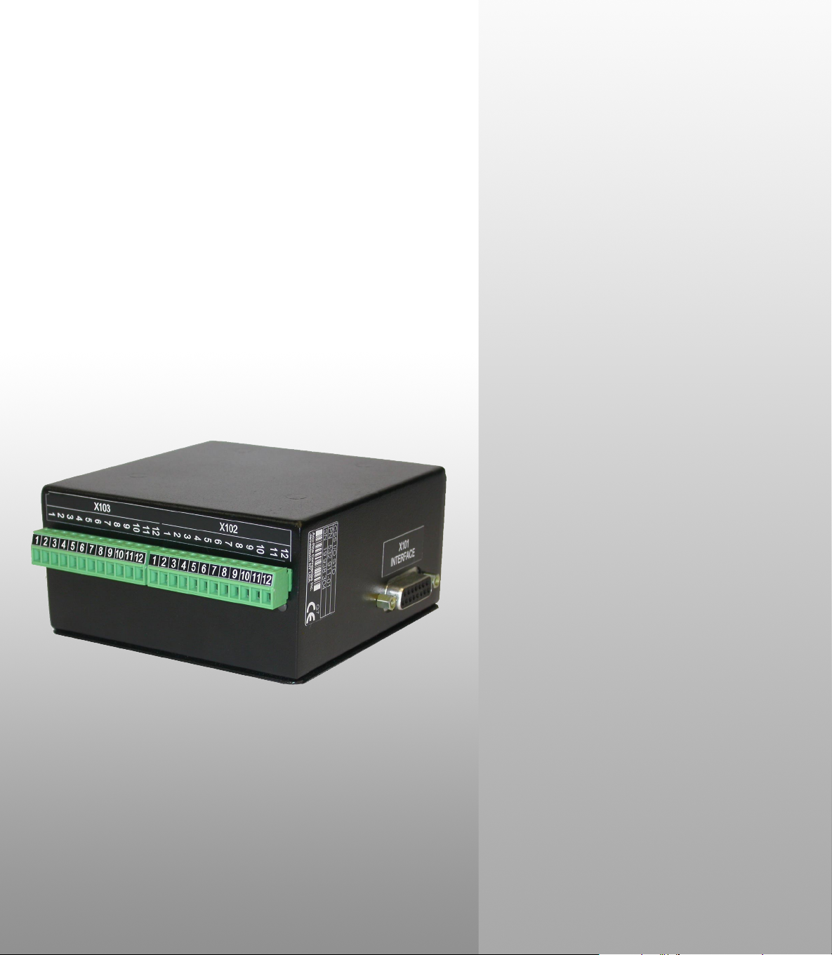
General Information
Connecting the CSS I/O to X101 for executing switching functions (milling) or controlling the constant surface speed CSS (turning)
When the CSS I/O is connected to DRO’s that support this feature, the
functionality described above are available. Contact an authorized
Acu-Rite product distributor for more information.
The DRO automatically recognizes when the CSS I/O is connected and
displays the CSS SETUP option or the SWITCHING OUTPUTS option in the
INSTALLATION SETUP menu. These options can be used to configure all
functions of the switching unit.
General Information
4 I Operating Instructions
Page 7
I - 1 Execution of Switching
Functions
If you want to use both the CSS I/O and the KT 130 edge finder at the
same time, or if you want to transmit measured values via the external
switching output, the distribution cable with ID 593761-01 is required.
Switching inputs
The CSS I/O provides four inputs that are used to zero the actual value
of the assigned axis. A low-to-high transition at the input causes the
value for that axis to be set to zero.
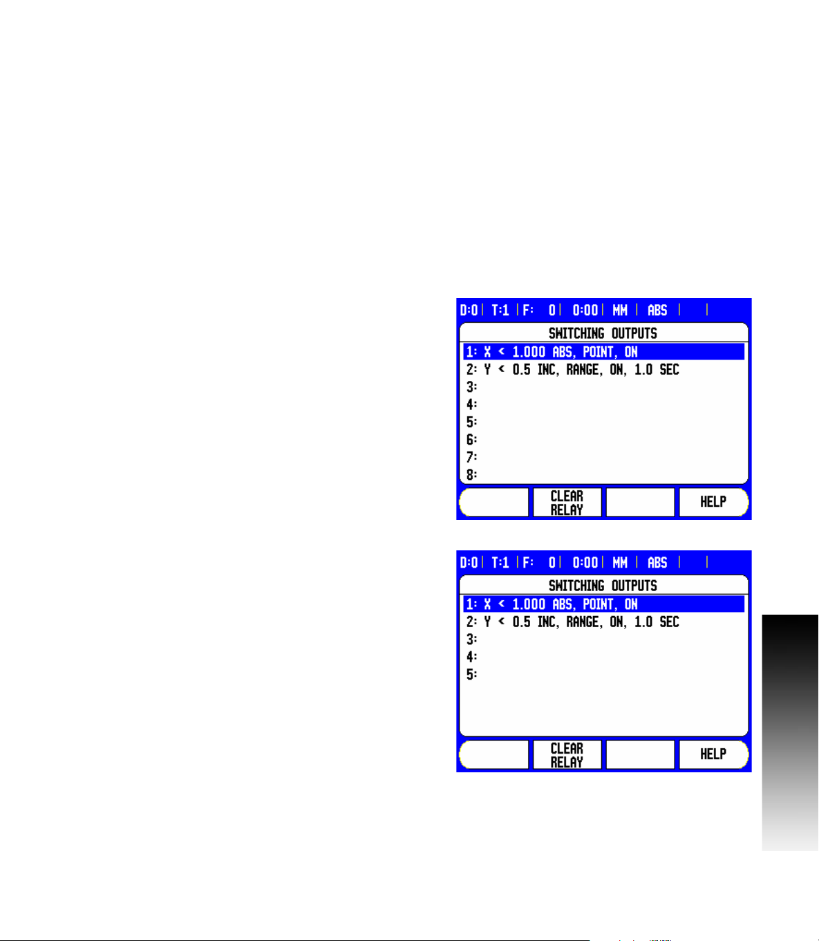
Switching outputs
The switching outputs consist of integrated relays available for generic
usage. The number of switching outputs available is dependent on the
configuration options chosen. When the system is configured for a
Mill, and the spindle speed control (RPM) is disabled, 8 switching
outputs are available. If RPM is enabled, then only 5 switching outputs
are available. See "Spindle Speed Control (RPM)" on page 8.
When the system is configured for a Lathe, and the constant surface
speed (CSS) is disabled, 8 switching outputs are available. If CSS is
enabled, then only 5 switching outputs are available. See "Controlling
the Constant Surface Speed (CSS)" on page 14.
I - 1 Execution of Switching Functions
The switching outputs are activated depending on “position”. The
relays can be configured to activate when a position display reaches a
specific value, or within a specified range of zero. The ninth output
relay indicates readiness.
Select SWITCHING OUTPUTS from the INSTALLATION SETUP menu
to open the SWITCHING OUTPUTS table in which the configuration of
the outputs are stored. If you want to change the configuration of an
output, select it with the arrow keys, and press ENTER to confirm your
selection. This opens the OUTPUT SETTINGS form in which you
define the switching conditions. To reset a relay, select the relay in the
table and press the CLEAR RELAY soft key, followed by the YES soft
key for confirmation.
CSS I/O 5
Page 8
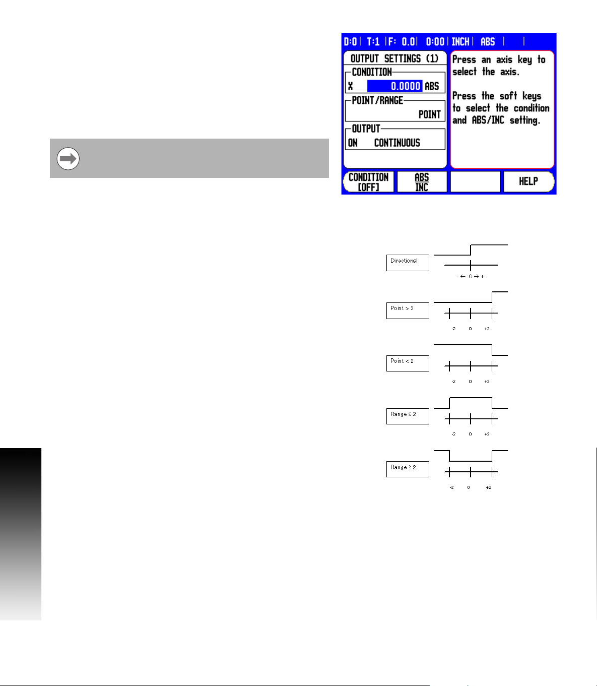
8 The CONDITION field is used to assign an axis to the output and to
specify whether the axis position is an actual-value or distance-to-go
position. You also specify the position display value at which the
relay is activated, and the required condition.
8 The POINT/RANGE field is used to define whether the conditions
refers to a point on the axis or refers to a range about zero.
8 The OUTPUT field is used to specify the relay operation when the
switching condition is met. When the condition is met, the relay is
turned OFF or ON.
If the condition is set to equal, the relay will activate
momentarily even if the switching point is crossed over too
quickly for the value to appear.
Possible switching states of the relays.
I - 1 Execution of Switching Functions
6 I Operating Instructions
Page 9
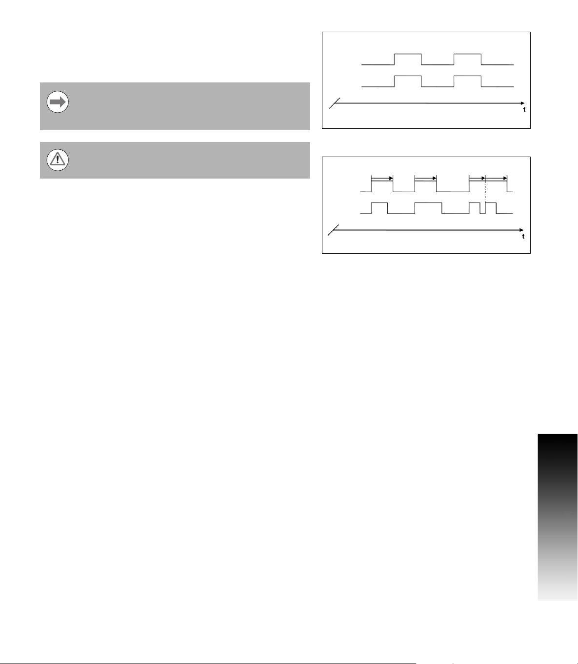
In PULSED mode, the relay is activated (ON or OFF) for a specific
period of time. After the period has timed out, the relay is deactivated.
The pulse time is 0.1 to 999 seconds.
Continuous mode shown:
The time period begins whenever the switching condition
transitions from FALSE to TRUE. If the switching conditions
transitions to TRUE before the period has timed out, the
timer will start over.
The switching functions cannot be used for coupled axes or
for axes with backlash compensation.
Relay
Condition
Pulsed mode shown:
Relay
Condition
I - 1 Execution of Switching Functions
CSS I/O 7
Page 10

I - 2 Spindle Speed Control (RPM)
Milling Systems
The Mill Spindle Speed Control is for milling systems only, and
provides an open loop spindle speed control.
The spindle speed control requires the CSS I/O box.
The spindle speed control is only available for milling
systems. If the DRO is configured for a turning system,
then no Spindle Settings will be displayed.
8 Define the last axis as a rotary encoder axis.
I - 2 Spindle Speed Control (RPM)
Display
8 Define the display as a speed display.
8 I Operating Instructions
Page 11

Mill Spindle Installation setup
The configuration parameters are found under Installation Setup. The
Spindle Settings only appear in the list if the CSS I/O box is detected.
8 Select Spindle Settings from the Installation Setup menu, and press
the ENTER key.
The spindle (RPM) status field allows the user to enable, or disable the
spindle (RPM) fuctionality. If it is disabled, then no spindle (RPM)
operations are available for usage. If the spindle (RPM) is enabled,
then all of the following setup must be completed. Six (6) generic
switching outputs will then be available.
I - 2 Spindle Speed Control (RPM)
CSS I/O 9
Page 12
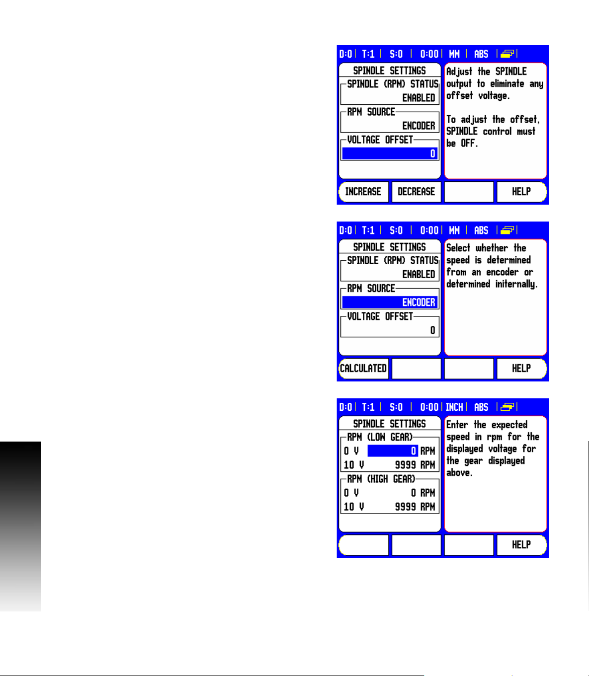
Voltage Offset / RPM Source
The voltage offset field is used to adjust for any inherent offset in the
DAC output. This value is added to the calculated DAC output. Use
a voltmeter to measure the actual voltage at the DAC output. Press
the INCREASE, or DECREASE soft key to adjust the offset until the
output is 0 V. The offset range is limited to 0 - 50, (approximately
0 - 122 mV).
8 Press ENTER to save the settings, and exit the form, or press the C
key to exit without saving the changes.
The RPM source allows the user to define whether the RPM source is
from an actual rotary encoder, or calculated by the software as a
replacement for a rotary encoder.
User speed limits can be established to limit how fast, or slow the
spindle may be run. These are run time limits, and must fit in within
I - 2 Spindle Speed Control (RPM)
the actual hardware limits.
8 Press ENTER to save the settings, and exit the form, or press the C
key to exit without saving the changes.
When in Setup mode, the status bar will display the current spindle
speed in RPM’s shown in the S: field on the status bar.
To set a specific spindle speed, the DAC output S
relationship to determine the corresponding output voltage V
V
= 10 • (S
Out
- S0) / (S10 - S0) + V
Out
Offset
uses this linear
Out
Out
:
Press ENTER to save the parameters and exit the input form. Press
the C key to exit without saving the changes.
These are the physical limits of the machine.
10 I Operating Instructions
Page 13
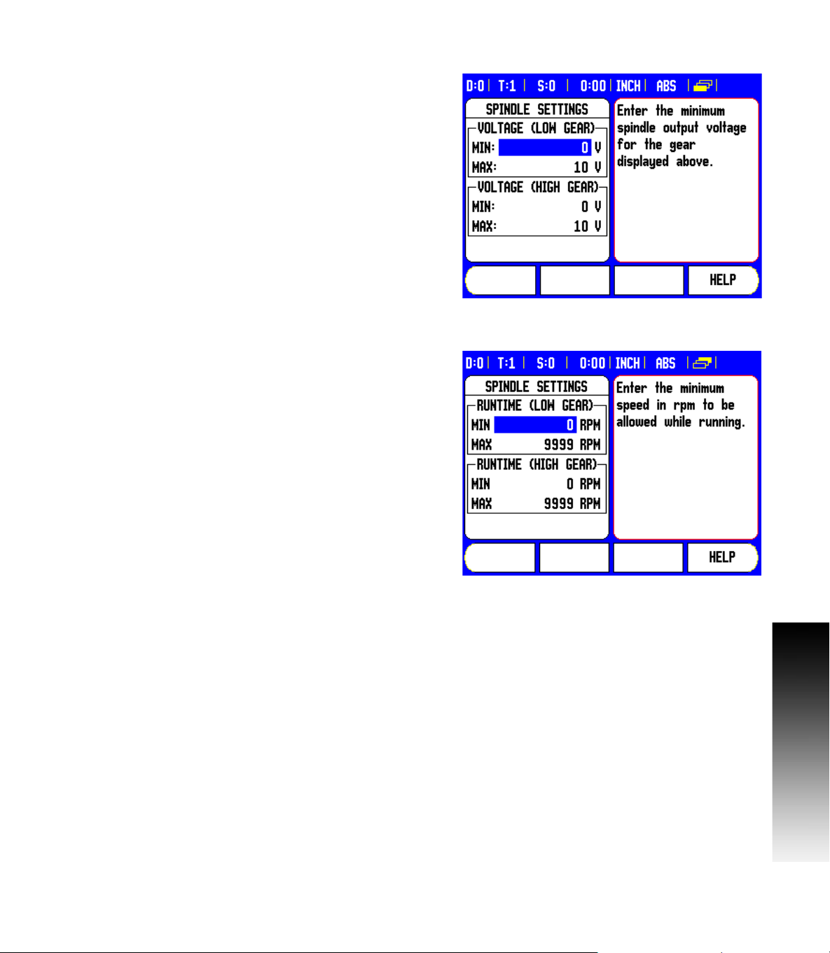
Voltage / RPM Setup
The voltage setup fields are used to establish the relationship
between the DAC output signal (0 - 10 V), and the spindle speed for
each gear.
8 Enter min, and max voltage levels for each gear.
8 Press ENTER to save the settings, and exit the form, or press the C
key to exit without saving the changes.
This screen allows the spindle to have min, and max RPM settings
defined. This limits the spindle not to exceed the limits set at start up.
The spindle speed can then be manually increment above the “Run
Time” limits.
8 After selecting Spindle Settings from the Installation Setup menu,
use the RIGHT or LEFT arrow hard keys to scroll to this menu.
I - 2 Spindle Speed Control (RPM)
CSS I/O 11
Page 14

Operation / Job Execution
The operation of the Mill Spindle is associated with the use of the
selected tool from the tool table, and the spindle parameters for
running the tool.
Refer to the DRO User’s Manual for setting up, and using a tool from
the tool table.
8 Select the desired tool from the tool table.
8 Press ENTER to open the tool setup form.
Press the RPM calc key to specify a surface speed, and get a resultant
RPM spindle speed that is automatically loaded into the tool table
when exiting the RPM calc.
I - 2 Spindle Speed Control (RPM)
12 I Operating Instructions
Page 15

A tool can be run from the tool table, or by pressing enter after defining
the spindle parameters for a tool.
Mill Spindle Feature Run
With all tool, job, and installation setups entered, the Mill Spindle job
can be run by toggling the Spindle ON/OFF soft key.
Select the tool to be used, and the required gear.
The spindle speed can be adjusted using the SPEED +/- soft keys.
Mill Spindle Program Run
Mill Spindle can be used within a program for any program step that
has a mill spindle tool defined for that step.
When in program run, if the SPINDLE: Direction, and Speed fields are
defined for the tool, the operator can use the LEFT, or RIGHT ARROW
keys to display the Spindle control soft keys. When these fields have
not been defined, the Spindle control soft keys are not available.
To go back to the program control screen from the mill spindle control,
press the LEFT, or RIGHT ARROW keys.
The speed of the mill spindle can also be adjusted while in the program
control screen by pressing the SPEED +/- soft keys.
I - 2 Spindle Speed Control (RPM)
CSS I/O 13
Page 16

I - 3 Controlling the Constant
Surface Speed (CSS)
In CSS mode, a constant surface cutting speed can be maintained on
a lathe. The following functions are available:
CSS mode: The DAC output signal provides constant surface speed
by adjusting the spindle speed as the diameter (radius) of the
workpiece changes.
Direct entry of spindle speed: The DAC output signal sets the
spindle speed based on the value entered via the numeric keypad.
Speed limits: The user may set a safe operating range (minimum
and maximum speeds) for spindle speed.
Gear selection: Three different gears can be specified for varying the
relation between the actual speed and the DAC output signal.
The READY output (X103-12) is active when the readout has
recognized the CSS I/O hardware, is monitoring the inputs, and is
controlling the output relays. If the CSS I/O detects a
communications error with the readout, the READY relay will be deenergized.
The CSS setting screen provides a choice between
STANDARD, LIMITED or DISABLED mode. This setting
should always be set to STANDARD mode.
When the CSS status field is set to disabled, then no CSS functionality
is available. Eight (8) generic switching outputs are available for
useage. When STANDARD, or LIMITED is selected, then the
remaining setup options must be completed. Only 5 generic
switching outputs will be available for usage.
I - 3 Controlling the Constant Surface Speed (CSS)
14 I Operating Instructions
Page 17

Configuration of CSS
To use the CSS functionality, the last axis must be defined as a rotary
axis. Define the display as a speed display, and configure them
accordingly. The spindle control configuration parameters are set up
in the INSTALLATION SETUP menu.
8 Select the CSS SETTINGS parameter to open the associated input
form
8 The CSS ON/OFF CONTROL field is used to specify whether the
CSS mode is operated by soft key or by an external hardware signal.
8 The current gear may be selected by local control (MANUAL via
CSS / DIRECT RPM in the JOB SETUP menu) or remote control
(EXTERNAL; via switches in the machine gear). This is defined in the
CSS GEAR SELECT field.
8 The VOLTAGE OFFSET function is used to adjust for any inherent
offset in the DAC signal. Using a voltmeter, measure the actual
voltage at the DAC output. Press INCREASE or DECREASE to adjust
the offset until the output is 0 V. The offset range is limited from 0
to 100 (approximately 0 to 244mV).
8 The VOLTAGE / RPM fields are used to establish the relationship
between the DAC output signal (0 to 10 V) and the spindle speed.
The minimum and maximum limits for each gear are entered.
If the position display of the third axis is configured to be used for the
spindle speed, the rpm in the SETTING field can be set to the current
spindle speed by pressing the TEACH soft key.
To set a specific spindle speed, the DAC output S
relationship to determine the corresponding output voltage V
V
= 10 · (S
Out
- S0) / (S10 - S0) + V
Out
Offset
Press ENTER to save the parameters and exit the input form. Press
the C key to exit without saving the changes you made.
uses this linear
Out
Out
:
CSS I/O 15
I - 3 Controlling the Constant Surface Speed (CSS)
Page 18

CSS operating mode
The operating parameters are set in the CSS / DIRECT RPM form.
8 Press the CSS SETUP soft key to open the form or select the
parameter from the JOB SETUP menu.
The SETTINGS field is used to select the mode of operation and the
control settings. The spindle is controlled by selecting CSS or by
entering the spindle speed directly. The values to be entered depend
on the selected option.
If CSS was selected to maintain a constant surface speed, the surface
speed entered with the numeric keys is maintained. As the diameter
of the part changes, the spindle speed will be adjusted.
8 To set a specific spindle speed, select DIRECT / RPM and enter the
value with the numeric keypad.
8 If the position display of the third axis is configured to be used for
the spindle speed, the rpm in the SETTING field can be set to the
current spindle speed by pressing the TEACH soft key.
8 Select OFF when spindle control is not needed.
8 The GEAR SELECTION field is used to manually enter the operating
gear with the numeric keypad.
If the gear control parameter in INSTALLATION SETUP is
set to EXTERNAL, the field will show the current gear
selection based on the external inputs. The field can then
not be selected and is skipped.
8 The LIMITS field is used to establish the minimum and maximum
limits of the controlled spindle speed. When operating in the CSS or
DIRECT RPM modes, the DAC output will not be set to a speed
above or below these limits.
8 Press ENTER to save the parameters and exit the input form. Press
I - 3 Controlling the Constant Surface Speed (CSS)
the C key to exit without saving the changes you made.
The “Spindle Speed” will default to the OFF position when ever the
Readout power is cycled, and the run mode must be reselected to
use. No settings are lost when power is cycled. The Max RPM field
is discarded between runs in Limited mode only, requiring to teach
a new max RPM each time.
16 I Operating Instructions
Page 19

Activating the DAC output
After selecting the operating mode and entering its parameters, the
DAC output must be enabled to begin controlling the spindle.
The output to the spindle inverter drive is an open loop signal. The
system does not monitor the actual spindle speed. The output signal
is based solely on the inverter's speed input versus the input voltage
profile.
8 Depending on the operating mode selected, the RPM or CSS soft
key is displayed on the fourth page of the soft key menu. If the
current state indicated on the soft key is ON, the DAC output is
active. Press the soft key to OFF to disable the spindle control.
If CSS is active, the CSS icon appears next to the X-axis display. If the
entered surface speed or rpm cannot be maintained because the
speed is outside the range for the current gear or outside the limits
from the CSS/RPM SETTINGS form, an arrow will appear after the
CSS icon ( or ). The direction of the arrow indicates
whether the speed is at the upper or lower limit.
The soft key to enable CSS or RPM control will not appear
if the operating mode is set to OFF.
If the CSS control parameter under INSTALLATION SETUP
is set to EXTERNAL, the CSS or RPM operation cannot be
controlled by soft key. The soft key will show the current
state, but pressing it will have no effect.
The SPEED + and SPEED – soft keys are used to increase or decrease
the current surface speed or spindle speed. The value is increased or
decreased by 5% each time the soft key is pressed.
I - 3 Controlling the Constant Surface Speed (CSS)
CSS I/O 17
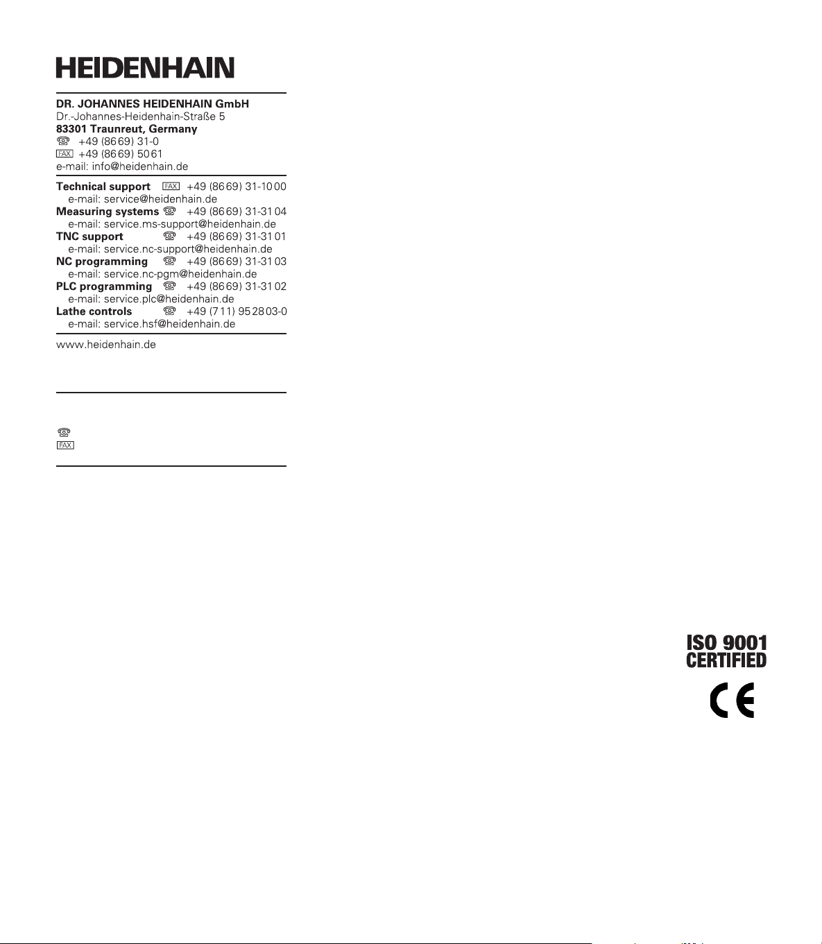
Page 20
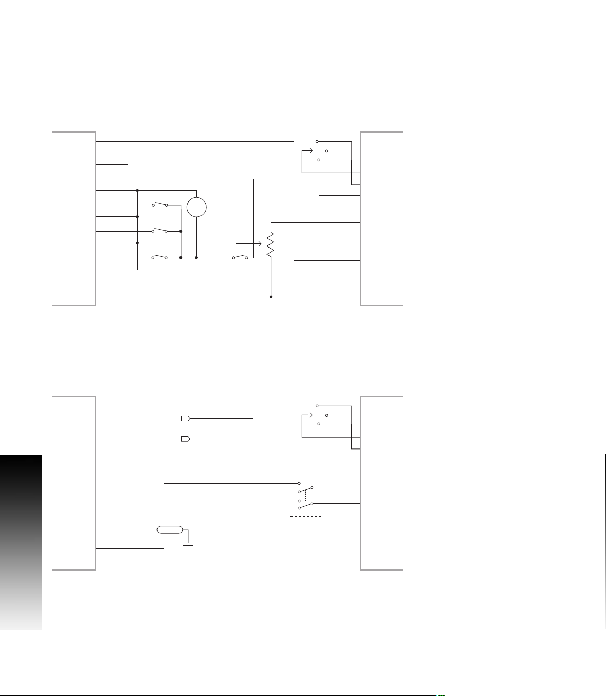
Connecting the CSS I/O to the inverter of the
X1039
X10310
X10311
X1021
X1022
X1023
X1024
X1025
X1026
X1027
X1028
X10211
X10212
MANUAL
RPM
+
1224 VDC
100 mA
OFF
FORWARD
REVERSE
ANALOG SUPPLY
ANALOG INPUT
ANALOG COMMON
TURNING APPLICATION 1Automatic CSS/Pot Control
CSS I/0 INVERTER
DAC OUT
COMMON
GEAR 1
GEAR 2
GEAR 3
OUT 789
OUT 7
OUT 8
IN 0
IN 0+
IN 1
IN 1+
IN 2
IN 2+
IN 3
IN 3+
FWD
REV
INPUT+COMMON
X1039
X10310
X10311
OUT 789
OUT 7
OUT 8
X1021
IN 0
X1022
IN 0+
X1023
IN 1
X1024
IN 1+
X1025
IN 2
X1026
IN 2+
X1027
IN 3
X1028
IN 3+
X10211
X10212
DAC OUT
COMMON
CSS/pot Selector
CSS I/0 INVERTER
FWD
REV
OFF
INPUT+COMMON
FORWARD
REVERSE
ANALOG INPUT
ANALOG COMMON
V ref.+
V ref.
Pot on machine
TURNING APPLICATION 2Manual CSS/Pot Control
lathe
Example of gear detection and switching to manual spindle speed
control
I - 3 Controlling the Constant Surface Speed (CSS)
Example of switching to manual spindle speed control
18 I Operating Instructions
Page 21

I - 4 Diagnostics
General Information
When the CSS I/O box is connected to the DRO, the DIAGNOSTICS
menu under INSTALLATION SETUP provides further diagnostic
possibilities. The information available varies depending on the
configuration of the system, Switching I/O, CSS, or Mill Spindle
functions.
Switching I/O functions
The SWITCHING I/O DIAGNOSTICS shows the status of the
communication via the CAN bus and the state of the switching inputs
and outputs to provide monitoring of the switching functions.
The CAN STATUS field shows the state of the bus communication
between the DRO and the CSS I/O.
The status information has the following meaning:
Information Meaning
NOT PRESENT No communication with hardware
NOR Communication – normal operation
CAL Communication – Hardware in calibration
mode
Wen Watchdog active
Wds Watchdog inactive
Wto Watchdog time-out
Tx Data is transmitted to hardware
Rx Data is received by hardware
I - 4 Diagnostics
The SWITCHING I/O field shows the state of the inputs and the switch
position of the relays.
All currently active inputs (1 to 3) are shown in the ON field.
All currently active relay outputs (1 to 9) are shown in the OFF field.
The CALIBRATE soft key is used to re-synchronize the communication
with the CSS I/O. This, however, is only required if the module is not
detected upon power on.
CSS I/O 19
Page 22

CSS, and Mill Spindle
CSS / MS DIAGNOSTICS shows the status of the communication via
the CAN bus and the state of the DAC output to provide monitoring of
the interfaces for operation with constant surface speed, (or Mill
Spindle). The state of the switching inputs and outputs is also shown.
The CAN STATUS field shows the state of the bus communication
between the DRO, and the CSS I/O, (or Mill Spindle and I/O).
The status information has the following meaning:
I - 4 Diagnostics
Information Meaning
NOT PRESENT No communication with hardware
NOR Communication – normal operation
CAL Communication – Hardware in calibration
mode
Wen Watchdog active
Wds Watchdog inactive
Wto Watchdog time-out
Tx Data is transmitted to hardware
Rx Data is received by hardware
The DAC OUTPUT field shows the current value of the transmitted
voltage. The value is between 0 and 4095, which corresponds to a
voltage of 0 to 10 V at X102-11. The corresponding CSS icon will be
displayed if the spindle speed is at the upper or lower limit ( or
).
The CSS INPUT/OUTPUT field shows the state of the switching
inputs, and relay outputs.
20 I Operating Instructions
Page 23

For CSS only, the MS INPUT/OUTPUT field shows the state relay
outputs. The IN: field of the switching inputs is not used, and will be
blank.
The status information has the following meaning:
Information about
the inputs
EXT External switch is active (X102-12)
G1 Switch for gear 1 is active (X102-3,4)
G2 Switch for gear 2 is active (X102-5,6)
G3 Switch for gear 3 is active (X102-7,8)
The following table applies to both CSS, and RPM.
Information about
the outputs
POT Potentiometer relay is active (X102-10)
DAC DAC output relay is active (X102-11)
The CALIBRATE soft key is used to re-synchronize the communication
with the CSS I/O. This, however, is only required if the module was not
detected at switch-on.
Meaning
Meaning
I - 4 Diagnostics
CSS I/O 21
Page 24

I - 4 Diagnostics
22 I Operating Instructions
Page 25

A
Activating the DAC output ... 17
C
Configuration of CSS ... 9, 15
Connecting the CSS I/O to the inverter
of the lathe ... 18
Connecting the CSS I/O to X101 ... 4
Controlling the constant surface speed
(CSS) ... 8, 14
CSS ... 20
CSS DIAGNOSTICS ... 20
CSS operating mode ... 16
D
Diagnostics ... 19
E
Execution of switching functions ... 5
G
General Information ... 4, 5
M
Mill Spindle Installation setup ... 9
Mill Spindle Job Run ... 13
O
Operation / Job Execution ... 12
Index
R
Relay status ... 6
S
Spindle Speed Control (RPM) ... 8
SWITCHING I/O DIAGNOSTICS ... 19
Switching I/O functions ... 19
Switching inputs ... 5
Switching outputs ... 5
V
Voltage / RPM Setup ... 11
Voltage Offset / RPM Source ... 10
CSS I/O 23
Page 26

Index
Page 27

Page 28
HEIDENHAIN CORPORATION
333 East State Parkway
Schaumburg, IL 60173-5337 USA
+1 (847) 490-1191
+1 (847) 490-3931
E-Mail: info@heidenhain.com
www.heidenhain.com
638296-22 Ver 00 Printed in USA Subject to change without notice 02/2010
 Loading...