

Page 1
User’s Manual
Conversational and g-code
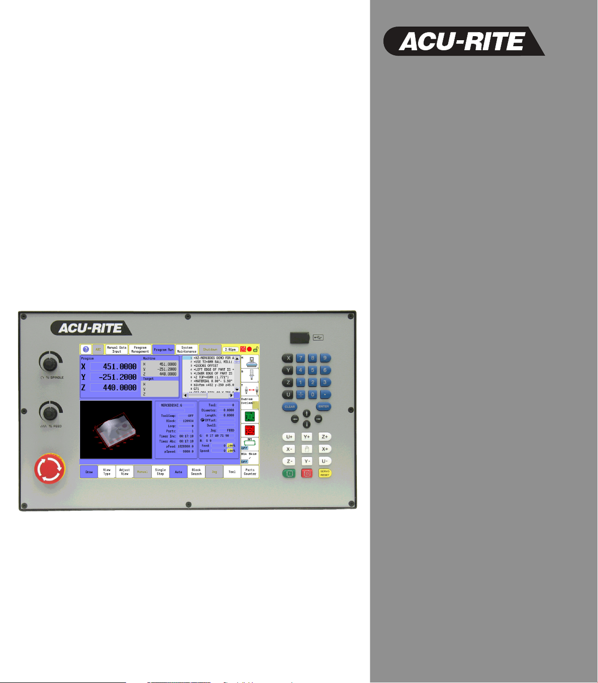
CNC 3500i
Page 2
Controls of the 3500i
Keys on visual display unit
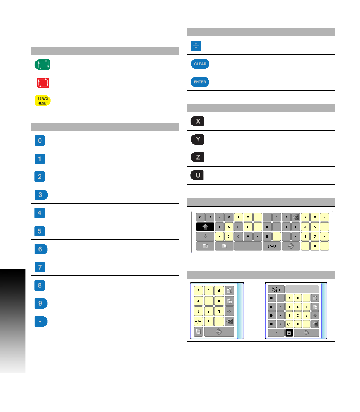
Power control keys
Key Function
Data Entry keys
Key Function
Plus - Minus toggle key
Controls of the 3500i
Numerical keys
Key Function
NC Start key (i.e. run a program)
Stop key (i.e. stop a program)
Servo Reset activates servo motors
Zero key
One key
Two key
Three key
Four key
Five key
CLEAR key clears selections, i.e. values,
ENTER key activates selections, and
entries
Axis Keys
Key Function
X Axis
Y Axis
Z Axis
U Axis
Touch QWERTY keyboard
Key Board
Six key
Seven key
Eight key
Nine key
Decimal key
ii
Numeric Touch Pad(s)
Numeric Pad Calculator Pad
Page 3
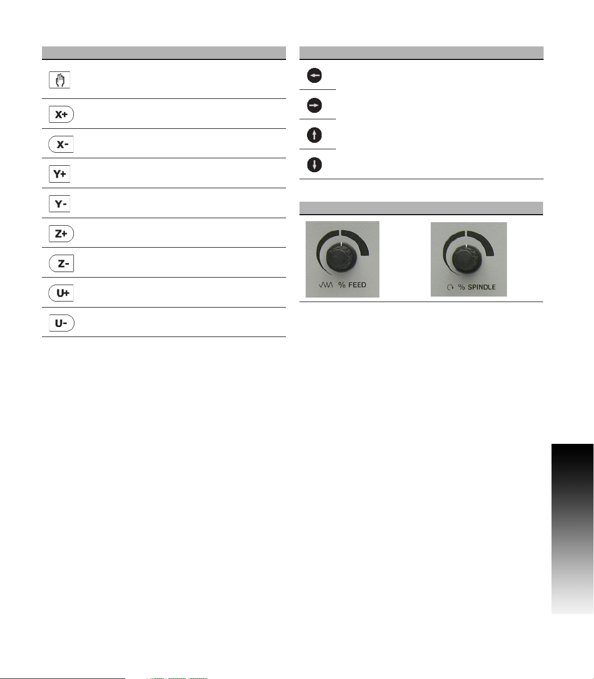
Axis Jog keys Navigation keys
Key Function
JOG Cycles the CNC through manual
movement modes: RAPID JOG, JOG
FEED, JOG @ 100, JOG @ 10, JOG @ 1
Manually moves X+ axis in positive
direction
Manually moves X- axis in negative
direction
Manually moves Y+ axis in positive
direction
Manually moves Y- axis in negative
direction
Manually moves Z+ axis in positive
direction
Manually moves Z- axis in negative
direction
Manually moves U+ axis in positive
direction
Manually moves U- axis in negative
direction
Key Function
ARROW over, up, down to move highlight
Potentiometer for feed rate and spindle speed override
Feed rate Spindle speed
Controls of the 3500i
ACU-RITE 3500i iii
Page 4
Keyboard Installation
The machine builder determines whether the system
supports a keyboard option. If this option is supported, plug
a USB keyboard into the 3500i.
There is no keyboard equivalent for the E-STOP,
so emergency shutdowns cannot be performed
through the keyboard.
Peripherals Supported:
USB memory devices; e.g. a memory stick.
USB pointing devices; e.g. a mouse.
USB Keyboards.
Controls of the 3500i
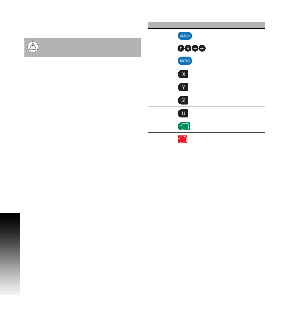
Keyboard Equivalent Key Strokes
Key Function
CLEAR Alt + c
ARROWS Arrows
ENTER Enter
X X
Y Y
Z Z
U U
START Alt + s
HOLD Alt + h
iv
Page 5

Manual Information
Message symbols
This symbol indicates that there is one or more of the
following risks when using the described function
Danger to work piece
Danger to fixtures
Danger to tool
Danger to machine
Danger to operators
Damage!
This symbol indicates that there is risk of damage, or
electrical shock if instructions are not adhered to.
Different from machine to machine!
This symbol indicates that instructions may apply
differently from one type of machine to another type of
machine.
Manual Information
Refer to another Manual!
This symbol indicates that information required is located
elsewhere (i.e. Machines Owner Manual).
Advice!
This symbol indicates that an Advice tip is being provided.
Important, and/or additional information about the function
described.
Fonts Used in this manual
3500i reference to the console KEYS
3500i reference to the touch screen Buttons
Changes (errors)
HEIDENHAIN Corporation is continuously striving to improve. Please
help HEIDENHAIN Corporation by sending your request to the
following e-mail address: sales@heidenhain.com
Visit www.acu-rite.com for latest version of this manual.
ACU-RITE 3500i v
Page 6

Model, Software and Features
This manual describes functions and features provided by 3500i as of
the following NC software numbers.
CNC model NC software number
ACU-RITE 3500i CNC Software 689 871-01
The machine tool builder adapts the usable features of the CNC to his
machine by setting machine parameters. Some of the functions
described in this manual may therefore not be among the features
provided by the CNC on your machine tool.
CNC functions that may not be available on your machine include:
Manual Information
Tool measurement with touch probes
The machine tool builder representative can assist with becoming
familiar with the features of the machine.
Many machine manufacturers, as well as HEIDENHAIN Corp., offer
programming courses for the CNC. We recommend these courses as
an effective way of improving your programming skill and sharing
information and ideas with other CNC users.
Intended place of operation
The CNC is intended for use primarily in industrially-zoned areas. Refer
to the respective installation manual for additional information.
vi
Page 7

New Functions of Software
689 871-01-02
CAM now includes a Save button to allow quickly saving progress.
Ctrl-S can now be used as well.
CAM geometry creation dialogs now support copying and pasting
between dialogs.
ARC Help Forms now support all planes. As such, X, Y, and Z
parameters are all available and indicated as optional. User needs to
decide which of these are actually required for the particular
instance.
The Edit Preview Features menu now includes a button to access
the Simulation Tool Table.
Tool and Offset Tables now support copying in both directions; from
Simulation to NC, and from NC to Simulation.
The use of the Sim Tool and Sim Offset tables are now configurable
See "Simulation Tool and Offset Tables" on page 71.
689 871-01-09
Added a new feature for custom OEMTEMPLATE program
template files. See "To create custom program templates:" on page
99.
Manual Information
ACU-RITE 3500i vii
Page 8

Changed Functions of Software
689 871-01-01
Feed & Speed Calculator in MDI was changed; see page 55.
Feeds & Speeds Table functionality and description was expanded;
see page 68.
Additional information for the Repeat blocks feature is being
provided; see page 147.
689 871-01-02
Linear and Arc Engraving cycles now apply active program rotation.
Mirroring and scaling are still cancelled at the start of the cycle. No
Manual Information
rotation, mirroring, or scaling is active after these cycles have run,
and would need to be reprogrammed if desired; see page 110.
Tool Table Teach and Teach Program buttons are now configurable
as to their positions on the menu; see page 66.
The setting to hide or show the on-screen keyboard is now
persistent across machine power cycles; see page 13.
689 871-01-03
Rotation cycles (G68 and RMS) now allow user to specify if the
rotation center is a pivot point for the rotation or not; see page 239.
A circle of the format XYR with start=end now generates an error
because it cannot be properly calculated; see page 134.
The M98 Help Form now includes the previously missing Loop
parameter; see page 238.
689 871-01-04
The Conversational Editor now always ensures that a blank line
exists at the end of programs, in order to make it easy to insert new
blocks at the end of the program; see page 112.
When turning OFF Edit Preview, the active program preview run is
now cancelled. Also, the Preview Features menu is now available
while the program preview is running; see page 116.
689 871-01-05
Added description of estimated machining time in preview image;
see page 93.
Outdated estimated machining times are now displayed on the
preview image in RED colored text; see page 93.
689 871-01-08
Corrected total number of available tools (100); see page 61.
Additional information has been added for islands; see page 192.
Added examples of pockets with islands; see page 241.
689 871-01-09
Pocket cycles now allow changing the direction of the Roughing
Pass, and as such the previous 'FinishDir' parameter has been
superseded by a new 'Direction' parameter, which now applies to
both the Roughing and Finishing passes; see page 171
viii
Page 9

Contents
Introduction
1
Machining Fundamentals
2
Manual Data Input
3
Tool Management
4
Program Management
5
Conversational Editing
6
Programming: Canned Cycles, subprograms
7
Drawing Programs
8
Running a Program on the Machine
9
CAM: Programming
10
G-code Edit, Help, & Advanced Features
11
Software Update
12
ACU-RITE 3500i ix
Page 10

x
Page 11

Table of Contents
Controls of the 3500i
Keys on visual display unit .......................................................................................iv
Numerical keys ........................................................................................................iv
Data Entry keys........................................................................................................iv
Axis Keys .................................................................................................................iv
Touch QWERTY keyboard .......................................................................................iv
Numeric Touch Pad(s)..............................................................................................iv
Axis Jog keys............................................................................................................v
Navigation keys.........................................................................................................v
Potentiometer for feed rate and spindle speed override ..........................................v
Keyboard Installation................................................................................................vi
Keyboard Equivalent Key Strokes ............................................................................vi
Manual Information
Message symbols...................................................................................................vii
Fonts Used in this manual .................................................................................vii
Model, Software and Features .............................................................................. viii
Intended place of operation .............................................................................. viii
New Functions of Software .....................................................................................ix
689 871-01-02.....................................................................................................ix
689 871-01-09.....................................................................................................ix
Changed Functions of Software ...............................................................................x
689 871-01-01......................................................................................................x
689 871-01-02......................................................................................................x
689 871-01-03......................................................................................................x
689 871-01-04......................................................................................................x
689 871-01-05......................................................................................................x
689 871-01-08......................................................................................................x
689 871-01-09......................................................................................................x
Introduction
1.1 The 3500i
ACU-RITE conversational, and G-code formats ....................................................... 2
Powering Up the CNC Machine............................................................................... 3
E-Stop, Servo Reset, and CNC Shutdown ............................................................... 4
Writing Programs..................................................................................................... 5
3500i xi
Page 12

1.2 Visual Display Unit
Operating Panel with Touch Screen display ............................................................ 6
Screen Navigation.................................................................................................... 6
Menus, Dialogues, and Forms ................................................................................. 7
General Operating Guidelines .................................................................................. 8
Main Operating Modes....................................................................................... 8
Sub Modes ......................................................................................................... 9
Upper Menu and Status Information Bar.......................................................... 10
Machine function buttons ................................................................................. 11
Keyboard........................................................................................................... 12
Additional Buttons ............................................................................................ 13
Special Characters ............................................................................................ 13
Programming Sliders ........................................................................................ 14
Numeric touch pad ........................................................................................... 15
Calculator .......................................................................................................... 16
Advanced Function buttons .............................................................................. 16
Context Sensitive Help .......................................................................................... 17
Using Context Sensitive Help ........................................................................... 17
Console Key Pad.................................................................................................... 19
1.3 Main Operating Mode Screens
Display navigation .................................................................................................. 20
Manual Data Input ................................................................................................. 20
Program Management Screen............................................................................... 21
Program Run.......................................................................................................... 22
1.4 Accessories:
Touch probes ......................................................................................................... 23
HR electronic hand wheels.................................................................................... 24
Electronic Edge Finder........................................................................................... 24
Machining Fundamentals
2.1 Fundamentals of Positioning
Position encoders and reference marks ................................................................ 26
Reference system ................................................................................................. 27
Reference system on milling machines................................................................. 27
Designation of the axes on milling machines ........................................................ 28
Polar coordinates ................................................................................................... 28
Setting the pole and the angle reference axis .................................................. 29
Absolute and incremental polar coordinates..................................................... 29
Angle Measurements ....................................................................................... 30
xii
Page 13

Absolute and incremental work piece positions .................................................... 31
Absolute work piece positions.......................................................................... 31
Incremental work piece positions..................................................................... 31
Setting the datum .................................................................................................. 32
Fixture Offsets .................................................................................................. 32
2.2 Manual Machine Positioning
Jog Mode Moves................................................................................................... 34
Changing the Jog Mode.................................................................................... 34
Incremental Moves ........................................................................................... 34
Continuous Moves............................................................................................ 34
Adjusting the Feedrate...................................................................................... 35
Overriding the Spindle RPM .................................................................................. 35
Manual Data Input
3.1 Manual Data Input (MDI)
Overview ............................................................................................................... 38
Manual Data Input Screen ..................................................................................... 38
Manual Data Input Mode Settings......................................................................... 39
Manual Data Input Menu Bar................................................................................. 40
MDI Menu Page two ........................................................................................ 41
Manual Data Input Operations ............................................................................... 42
Manual Data Input Cycles ...................................................................................... 44
Pocket Cycle Example ...................................................................................... 45
Block History.......................................................................................................... 47
G-code MDI .......................................................................................................... 48
MDI Touch Screen Feature Dialogues .................................................................. 49
Zero Axes.......................................................................................................... 49
Program Preset................................................................................................. 50
Move to Target Location................................................................................... 51
Tool ................................................................................................................... 52
Offset................................................................................................................ 53
Basic Modals..................................................................................................... 54
Feed and Speed................................................................................................ 55
MDI Teach ............................................................................................................. 57
3500i xiii
Page 14

Tool Management
4.1 Tool Table
Tool Table / Tool Management .............................................................................. 60
Tool Compensation Required Data ........................................................................ 60
Tool numbers / Tool names ................................................................................... 61
Locating the Tool Table.......................................................................................... 61
Editing the tool table.............................................................................................. 62
Tool Table Menu Bar......................................................................................... 62
Second Menu Bar ............................................................................................. 63
Clearing an entire line of tool data .................................................................... 64
Clearing the current tool table .......................................................................... 64
Find ................................................................................................................... 65
Finding a tool using text.................................................................................... 65
Clear Feature .................................................................................................... 66
Teach, and Teach Program ............................................................................... 66
Tool Table Structure .............................................................................................. 67
Tool table: Standard tool data ........................................................................... 67
Feeds & Speeds Table........................................................................................... 68
Feeds & Speeds Overview ............................................................................... 68
Feeds & Speeds Table Structure ...................................................................... 68
Using the Feeds & Speeds Table ..................................................................... 70
Simulation Tool and Offset Tables......................................................................... 71
4.2 Tool Data
T-Codes, and Tool Activation ................................................................................. 72
Activating Offsets via the Program ........................................................................ 72
Tool-Length Offsets............................................................................................... 73
Entering Tool Length Offsets in the Tool Table ................................................ 73
Diameter Offset in Tool Table................................................................................ 74
Tool Radius Compensation .................................................................................... 75
Contouring without radius compensation......................................................... 75
Contouring with radius compensation .............................................................. 76
Radius compensation: Machining corners........................................................ 77
Ramping into a Compensation Move ............................................................... 78
Line Tangent Entry Move ................................................................................. 78
Line Perpendicular Entry Move......................................................................... 78
Arc Tangent Entry Move................................................................................... 79
Line Arc Tangent Entry Move ........................................................................... 79
Special Code: Temporary Change of Tool Diameter......................................... 80
xiv
Page 15

Tool Compensation Path........................................................................................ 81
Path of Tool During Tool Compensation ........................................................... 81
Intersecting Points ............................................................................................ 82
Compensation Around Acute Angles................................................................ 82
General Precautions............................................................................................... 83
Fixture Offsets - Tool menu................................................................................... 84
Tool Life Management........................................................................................... 84
Activate Tool Life Management........................................................................ 84
Lock, or Unlock a Tool....................................................................................... 85
Replacement Tool (RT)...................................................................................... 85
Program Management
5.1 Program Management Introduction
Accessing Program Management ......................................................................... 88
Program Screen Description .................................................................................. 88
Program Manager Menu Bar ................................................................................. 89
Utility Function Buttons ......................................................................................... 90
Display window arrangement ................................................................................ 91
5.2 Program Manager Functions
Folder Filter............................................................................................................ 92
Advanced Folder Filter ........................................................................................... 92
Utility Button Functions ......................................................................................... 93
Sorting Folder Contents......................................................................................... 95
Program Properties................................................................................................ 95
Recycle Bin ............................................................................................................ 96
USB Access ........................................................................................................... 96
5.3 Creating, Editing, & Selecting to Run
Creating a New Part Program ................................................................................ 97
Editing an Existing Part Program ........................................................................... 97
Selecting a Program To Run .................................................................................. 98
Program selection:............................................................................................ 98
Using custom program templates ......................................................................... 99
To create custom program templates:.............................................................. 99
3500i xv
Page 16

Conversational Editing
6.1 Conversational Programming
Getting Started .................................................................................................... 102
Program Edit Screen............................................................................................ 103
Program Edit buttons...................................................................................... 104
Conversational Data Input Cycles ........................................................................ 105
Milling Button ................................................................................................. 105
Milling Feature Buttons .................................................................................. 106
More Milling Button........................................................................................ 107
Drill Features Button....................................................................................... 108
Pocket Cycles Button ..................................................................................... 109
Other Cycles Button ....................................................................................... 110
Program Editing ................................................................................................... 111
Mark a program block: .................................................................................... 111
Unmark a block, or blocks:.............................................................................. 111
Deleting a program block:............................................................................... 112
Inserting a program block: .............................................................................. 112
Copy/Paste Blocks in a program ..................................................................... 113
Moving Blocks in a program ........................................................................... 113
Canceling edits to a program block:................................................................ 113
Restore edits to a program block:................................................................... 114
Editing an existing block: ................................................................................ 114
Inserting program blocks using keypad hotkeys:............................................ 114
Program Text Editing ........................................................................................... 115
Find: Specific Text or Code in a program........................................................ 115
Program Edit Preview .......................................................................................... 116
Preview Side Bar Menu .................................................................................. 116
Preview Features Menu ................................................................................. 117
Program / Display Relation................................................................................... 118
Programming: Canned Cycles, sub-programs
7.1 Explaining Basic Cycles
Round/Chamfer.................................................................................................... 120
Corner Rounding............................................................................................. 120
Line-to-Line Corner Rounding ......................................................................... 120
Line-to-Arc Corner Rounding .......................................................................... 121
Arc-to-Arc Corner Rounding ............................................................................ 121
Chamfering ..................................................................................................... 121
xvi
Page 17

Rapid.................................................................................................................... 122
Rapid Move..................................................................................................... 122
Rapid Move - EndPoint: .................................................................................. 122
Rapid Move - Angle and Radius:..................................................................... 123
Rapid Move - Angle and X:.............................................................................. 123
Rapid Move - Angle and Y:.............................................................................. 124
Rapid Move - Radius and X: ............................................................................ 124
Rapid Move - Radius and Y: ............................................................................ 125
Line ...................................................................................................................... 125
Line Move:...................................................................................................... 125
Line Move - EndPoint:..................................................................................... 126
Line Move - Angle and Radius: ....................................................................... 127
Line Move - Angle and X:................................................................................ 127
Line Move - Angle and Y:................................................................................ 128
Line Move - Radius and X: .............................................................................. 128
Line Move - Radius and Y: .............................................................................. 129
Arc ....................................................................................................................... 130
Arc Move: ....................................................................................................... 130
Arc Move - Radius and EndPoint: ................................................................... 131
Arc Move - Center and EndPoint: ................................................................... 132
Arc Move - Center and Angle:......................................................................... 133
Using Arc Center and EndPoint to create a circle ........................................... 134
Arc Move - Center and Angle, Absolute mode: .............................................. 134
Arc Move - Center and Angle, Incremental mode: ......................................... 134
Dwell:................................................................................................................... 135
Plane Selection .................................................................................................... 136
Reference Point Return: ...................................................................................... 137
Fixture Offset (Work Coordinate System Select):................................................ 138
Unit (Inch/MM)..................................................................................................... 139
Dimension (Abs/Inc)............................................................................................. 139
Absolute Zero Set ................................................................................................ 140
Block Form........................................................................................................... 141
Temporary Path Tolerance ................................................................................... 142
System Data ........................................................................................................ 143
FeedRate ............................................................................................................. 144
FeedRate (4th-Axis) ............................................................................................. 144
Spindle RPM ........................................................................................................ 145
M - Functions....................................................................................................... 145
Tool Definition and Activation .............................................................................. 146
Repeat Blocks...................................................................................................... 147
3500i xvii
Page 18

7.2 Canned Cycles
Canned Cycles ..................................................................................................... 149
Drilling Cycles ...................................................................................................... 150
Drilling, Tapping, and Boring ........................................................................... 150
Basic Drill Cycle .............................................................................................. 150
Counterbore Drill Cycle................................................................................... 151
Peck Drill Cycle ............................................................................................... 151
Tapping Cycle ................................................................................................. 152
Boring Bidirectional Cycle ............................................................................... 153
Boring Unidirectional Cycle ............................................................................. 153
Chip Break Cycle............................................................................................. 154
Flat Bottom Boring Cycle................................................................................ 155
Drill Bolt Hole Cycle ........................................................................................ 156
Drill Pattern Cycle ........................................................................................... 157
Milling Cycles....................................................................................................... 158
Mill Cycle ....................................................................................................... 158
EndMill Cycle .................................................................................................. 160
Face Mill Cycle................................................................................................ 161
Hole Mill Cycle................................................................................................ 163
Thread Mill Cycle ............................................................................................ 164
Circular Profile Cycle....................................................................................... 167
Rectangular Profile Cycle................................................................................ 169
Pocket Cycles ...................................................................................................... 171
Pocket Cycle Overview: ................................................................................. 171
Draft Angle Pocket Cycle................................................................................ 172
Rectangular Pocket Cycle ............................................................................... 174
Circular Pocket Cycle ...................................................................................... 176
Plunge Rectangular Pocket Cycle ................................................................... 178
Plunge Circular Pocket Cycle .......................................................................... 180
Frame Pocket Cycle........................................................................................ 182
Ring Pocket Cycle........................................................................................... 184
Slot Cycle........................................................................................................ 186
Circular Slot Cycle........................................................................................... 188
Irregular Pocket Cycle .................................................................................... 190
Islands............................................................................................................. 192
Bottom Finish ................................................................................................. 193
Side Finish ..................................................................................................... 194
Engraving Cycles ................................................................................................. 195
Programming the Engrave Cycle .................................................................... 195
Programming the Arc Engrave Cycle .............................................................. 197
xviii
Page 19

7.3 Probing Cycles
Tool, and Spindle Probe cycles............................................................................ 199
Tool Probe Cycles ................................................................................................ 200
Tool Probe Calibration Cycle ........................................................................... 201
Tool Length and Diameter Offset Preset........................................................ 203
Manual Tool-Length Offset Preset.................................................................. 210
Manual Tool Diameter Measure for Special Tools.......................................... 213
Tool Breakage, Length and Diameter Wear Detection .................................. 216
Spindle Probe....................................................................................................... 219
Spindle Probe Cycles ...................................................................................... 219
Spindle Probe Settings.................................................................................... 219
Spindle Probe Calibration Cycle ...................................................................... 220
Edge Finding ................................................................................................... 222
Outside Corner Finding .................................................................................. 223
Inside Corner Finding ..................................................................................... 225
Inside/Outside Boss/Hole Finding .................................................................. 227
Inside/Outside Web Finding ........................................................................... 229
Protected Probe Positioning .......................................................................... 231
Skew Compensation ...................................................................................... 232
Using the Z Work Offset Update Feature ....................................................... 235
7.4 Sub-programs
Sub-program information: .................................................................................... 236
Overview......................................................................................................... 236
Ending the Main Program ............................................................................... 236
Defining a sub-program ....................................................................................... 237
Ending a sub-program.......................................................................................... 237
Calling a sub-program .......................................................................................... 237
Looping a sub-program ........................................................................................ 238
Rotate, Mirror, and/or Scale a sub-program......................................................... 239
Pocket and Islands example ................................................................................ 241
Pocket/Island example 1 ................................................................................. 241
Pocket/Island example 2 ................................................................................. 243
Pocket/Island example 3 ................................................................................. 245
Pocket/Island example 4 ................................................................................. 247
Pocket/Island example 5 ................................................................................. 249
Pocket/Island example 6 ................................................................................. 251
3500i xix
Page 20

Drawing Programs
8.1 Draw
Viewing Programs ............................................................................................... 256
Starting Draw....................................................................................................... 257
View Options Menu............................................................................................. 258
Adjust View Menu ............................................................................................... 259
Adjust Block Form ............................................................................................... 260
Zoom.................................................................................................................... 260
Rotate Drawing View........................................................................................... 261
Pan Drawing View ............................................................................................... 261
Line View Adjustments........................................................................................ 262
Draw Options....................................................................................................... 263
Sim Tools ............................................................................................................. 264
Running a Program on the Machine
9.1 Running a program
Modes of Programmed Operation ....................................................................... 266
Auto mode ........................................................................................................... 266
Starting a program .......................................................................................... 267
Pause, or Stop a running program .................................................................. 267
Clearing a Messages ........................................................................................... 267
Single Step........................................................................................................... 268
Block Search ........................................................................................................ 269
Select a Starting Block.................................................................................... 269
Using Draw with running programs..................................................................... 270
Program Status Area............................................................................................ 271
Parts Counter....................................................................................................... 272
Program Run Timers............................................................................................ 273
Accessing the Tool Table..................................................................................... 273
Axis Jog keys....................................................................................................... 274
In-Program Axis Jogging...................................................................................... 275
CAM: Programming
10.1 CAM Programming
CAM Mode .......................................................................................................... 278
Recommended CAM Programming Sequence ................................................... 279
CAM Setup ..................................................................................................... 279
Geometry Data .............................................................................................. 279
Job Setup........................................................................................................ 279
xx
Page 21

CNC Program.................................................................................................. 279
CAM Mode Mouse Operations ........................................................................... 280
CAM Mode Screen .............................................................................................. 281
Activating CAM Mode ......................................................................................... 281
Creating a New Program ..................................................................................... 282
CAM Mode buttons ........................................................................................ 282
Geometry Toolbar buttons: ............................................................................. 282
Point Tool buttons........................................................................................... 283
Point Editing.................................................................................................... 283
Line Tool buttons ............................................................................................ 284
Editing a Line .................................................................................................. 285
Circle Tool buttons .......................................................................................... 286
Circle Editing................................................................................................... 286
Shape Tool buttons......................................................................................... 287
Tool Path Buttons ........................................................................................... 288
Tool Path Data Input ............................................................................................ 289
Quick Coordinate Entry ........................................................................................ 290
Job Setup: Basic tab ............................................................................................ 291
Basic tab Data Entries .................................................................................... 291
Job Setup: Advanced tab .................................................................................... 293
Advanced tab Data Entries.............................................................................. 293
Comment Tab ...................................................................................................... 294
Block Form: Basic tab .......................................................................................... 295
Basic tab Data Entries..................................................................................... 295
Comment Tab ...................................................................................................... 295
Drilling Cycle: ....................................................................................................... 296
Drill Cycle: Basic ............................................................................................ 296
Drill Cycle: Counterbore ................................................................................. 296
Drill Cycle: Peck .............................................................................................. 296
Drill Cycle: Tapping ......................................................................................... 296
Drill Cycle: Boring Bidirectional....................................................................... 296
Drill Cycle: Boring Unidirectional..................................................................... 297
Drill Cycle: Chip Break..................................................................................... 297
Drill Cycle: Flat Bottom Boring........................................................................ 297
Drilling dialogue: .................................................................................................. 298
Basic tab ......................................................................................................... 298
Setup tab:........................................................................................................ 299
Bolt Hole tab: .................................................................................................. 299
Pattern tab: ..................................................................................................... 300
Comment tab:................................................................................................. 300
Mill Cycle ............................................................................................................. 301
Basic tab: ........................................................................................................ 301
Setup tab:........................................................................................................ 302
3500i xxi
Page 22

Pocket Cycle ........................................................................................................ 303
Basic tab: ........................................................................................................ 303
Setup tab: ....................................................................................................... 303
Pocket Finish Cycles............................................................................................ 305
Bottom tab:..................................................................................................... 305
Side tab:.......................................................................................................... 305
Adding a Machining Side: ............................................................................... 306
Engraving Cycle ................................................................................................... 307
Basic tab: ........................................................................................................ 307
Setup tab: ....................................................................................................... 308
Comment tab:................................................................................................. 308
Program Directive ................................................................................................ 308
Adding a Program Directive ............................................................................ 308
Modifying Toolbar ................................................................................................ 309
Modifying Tools Buttons:................................................................................ 309
Viewing Tools ...................................................................................................... 310
Viewing Tool Buttons:..................................................................................... 310
CAM Mode buttons ............................................................................................. 311
CAM Tool Buttons: ......................................................................................... 311
CAM Setup .......................................................................................................... 313
Selection tab: .................................................................................................. 313
Output tab:...................................................................................................... 313
Display tab: ..................................................................................................... 314
Tool Table tab: ................................................................................................ 314
View Buttons: ................................................................................................. 315
Geometry............................................................................................................. 316
Defining Geometry: ........................................................................................ 316
Completing the Geometry: ............................................................................. 317
Finalizing the geometry................................................................................... 319
Creating the shape.......................................................................................... 320
DXF Import Feature ............................................................................................. 321
DXF Entities Supported .................................................................................. 321
DXF Entities Not Supported............................................................................ 321
Importing a DXF File ....................................................................................... 321
Modifying Tools ................................................................................................... 322
Corner Radius (inserting) ................................................................................ 322
Chamfer (inserting) ......................................................................................... 322
Trimming Geometry........................................................................................ 323
Delete button.................................................................................................. 323
Properties button ............................................................................................ 323
Shapes ................................................................................................................. 324
Copying a Shape ............................................................................................. 324
Moving a Shape .............................................................................................. 324
xxii
Page 23

Tool Table ............................................................................................................ 325
Setting up the Tool Table ................................................................................ 327
Importing a Tool Table .................................................................................... 327
Exporting a Tool Table..................................................................................... 327
Tool Paths ............................................................................................................ 328
Creating a Tool Path in CAM Mode ................................................................ 328
Tool Path Verification ...................................................................................... 328
Tool Path Editing............................................................................................. 329
Use Existing Shape......................................................................................... 329
Editing a Tool Path .......................................................................................... 330
Disabling, and Enabling Tool Paths ................................................................. 330
Deleting Tool Paths......................................................................................... 330
Arranging Tool Paths Sequence...................................................................... 330
Smart Programming........................................................................................ 331
Files Created................................................................................................... 331
CAM Example 1................................................................................................... 332
Exercise One:.................................................................................................. 332
Defining Geometry:......................................................................................... 332
Connecting the Geometry:.............................................................................. 334
Finalizing the geometry................................................................................... 335
Creating the shape.......................................................................................... 336
Creating the tool paths:................................................................................... 337
CAM Example 2................................................................................................... 341
Example Two: ................................................................................................. 341
Create Circle Geometry: ................................................................................. 341
Create Line Geometry..................................................................................... 343
Finalizing the geometry................................................................................... 344
Creating the shape.......................................................................................... 345
Creating the tool paths:................................................................................... 346
G-Code Edit, Help, & Advanced Features
11.1 G-Code Program Editing
Activating Edit Mode ........................................................................................... 352
Program Edit Screen............................................................................................ 353
Program Edit buttons ...................................................................................... 354
Edit Features menu......................................................................................... 355
Preview Features menu.................................................................................. 356
Program Editing ................................................................................................... 357
Mark a program block: .................................................................................... 357
Unmark a block, or blocks:.............................................................................. 357
Delete a Character: ......................................................................................... 358
Deleting a program block: ............................................................................... 358
Inserting a program block: .............................................................................. 359
Copy/Paste Blocks in a program ..................................................................... 359
Moving Blocks in a program ........................................................................... 360
3500i xxiii
Page 24

Canceling edits to a program block:................................................................ 360
Restore edits to a program block:................................................................... 360
Program Text Editing ........................................................................................... 361
Inserting Text:................................................................................................. 361
Overwriting Text: ............................................................................................ 361
Find: Specific Text or Code in a program........................................................ 362
Replace: Specific Text, or Code in a program................................................. 363
Preview Features................................................................................................. 364
Edit Features Menu ........................................................................................ 364
Program / Display Relation................................................................................... 365
Edit Help Preview .......................................................................................... 365
11.2 G-Code and M-Code Definitions
G-Code................................................................................................................. 366
M-Code Definition................................................................................................ 370
Typing in Address Words..................................................................................... 371
Typing in M-Codes............................................................................................... 371
11.3 Edit Help
Activating Edit Help ............................................................................................. 372
Help Graphic Screens .......................................................................................... 373
G - Functions........................................................................................................ 374
Basic Modal Functions.................................................................................... 375
Multi -Segment Blocks ................................................................................... 375
Arcs................................................................................................................. 376
Drilling Cycles ................................................................................................. 376
Pocket Cycles ................................................................................................. 377
Milling and Profiles ......................................................................................... 377
Rotation, Scaling, and Mirroring...................................................................... 378
Spindle Probing............................................................................................... 378
Tool Probing.................................................................................................... 379
Tool Radius Compensation ............................................................................. 379
Other G - Functions ........................................................................................ 380
M - Functions....................................................................................................... 381
All M - Functions............................................................................................. 381
Basic M - Functions ........................................................................................ 382
Cooling, Cleaning, and Lubrication.................................................................. 382
Spindle Functions ........................................................................................... 383
Tool Change.................................................................................................... 383
11.4 Advanced Programming
SPEED ................................................................................................................. 384
M - Functions....................................................................................................... 384
Miscellaneous (M-Code) ................................................................................. 384
Control M - Codes........................................................................................... 385
xxiv
Page 25

Order of Execution............................................................................................... 386
Programming Non-modal Exact Stop: ................................................................. 387
In-Position Mode (Exact Stop Check): ................................................................ 387
Contouring Mode (Cutting Mode) : ..................................................................... 387
Setting Stroke Limit: .......................................................................................... 388
Return from Reference Point: ............................................................................. 388
Move Reference from Machine Datum:.............................................................. 388
Modifiers.............................................................................................................. 389
Block Separators.................................................................................................. 389
Tool Offset Modification ...................................................................................... 390
Expressions and Functions .................................................................................. 393
System Variables ................................................................................................. 397
User Variables...................................................................................................... 398
Variable Programming (Parametric Programming) ............................................... 399
Block Skip ....................................................................................................... 399
Select Block Skip ............................................................................................ 400
Parameters and Variable Registers ................................................................. 401
Setting and Direct Transfer Variables.............................................................. 402
Indirect Transfer: ............................................................................................ 403
Storing Result of Computation........................................................................ 404
Variable Programming Examples .................................................................... 405
User Macros (G65, G66, G67)......................................................................... 409
Macro Body Structure..................................................................................... 410
Setting and Passing Parameters ..................................................................... 411
Probe Move (G31)................................................................................................ 422
Conditional Statements ....................................................................................... 423
Unconditional LOOP Repeat ........................................................................... 425
Short Form Addressing........................................................................................ 426
Logical and Comparative Terms .......................................................................... 427
File Inclusion ........................................................................................................ 429
11.5 Four Axis Programming
Axis Type ............................................................................................................. 432
Linear: ............................................................................................................. 432
Rotary:............................................................................................................. 432
Conversion formula: ....................................................................................... 432
Rotary Axis Programming Conventions .......................................................... 433
Programming Examples.................................................................................. 433
3500i xxv
Page 26

Software Update
12.1 Updating System Software
Software Update.................................................................................................. 438
Procedure for updating the software................................................................... 438
Off-Line Software
13.1 3500i Off-Line Software
Off-Line Simulator................................................................................................ 440
System Requirements ......................................................................................... 440
Installation............................................................................................................ 441
Operation ............................................................................................................. 441
Updating .............................................................................................................. 441
xxvi
Page 27
Introduction
Page 28
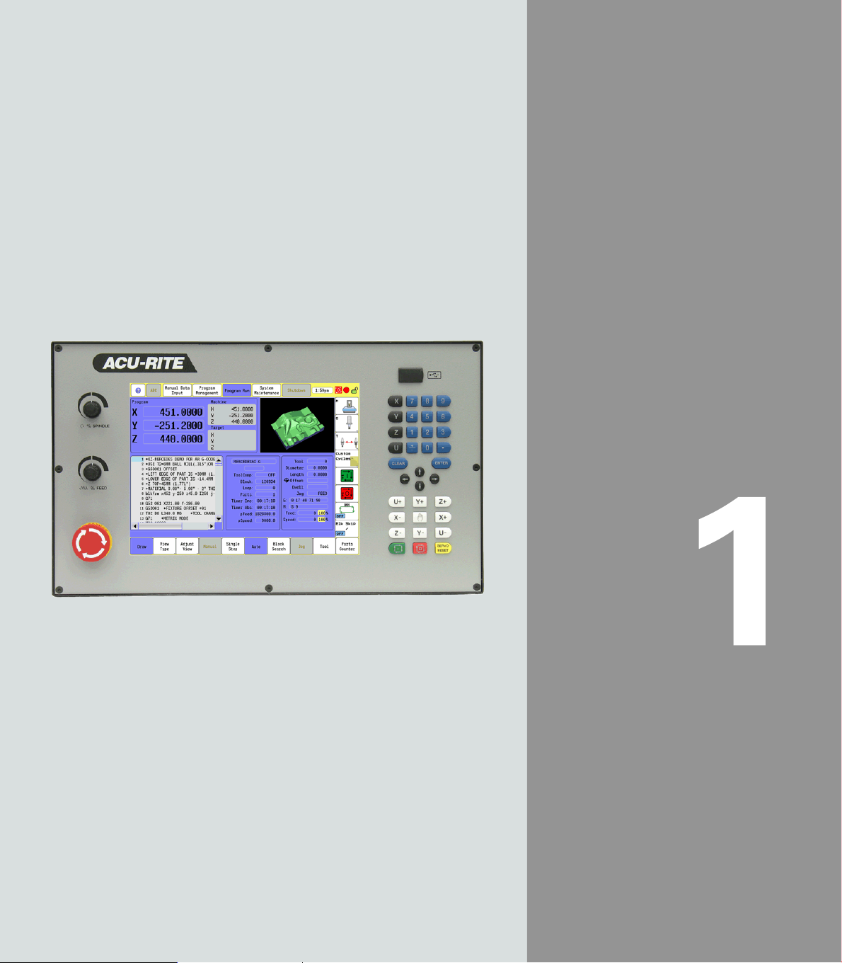
1.1 The 3500i
The ACU-RITE 3500i control is a touch screen workshop-oriented
contouring control that enables you to program conventional
machining operations right at the machine in an easy-to-use
conversational programming language. The control is also capable of
running, and editing g-code (ISO format) programs. It is designed for
milling and drilling machine tools, as well as machining centers, with
1.1 The 3500i
up to four axes. You can also change the angular position of the
spindle under program control.
The 3500i has many powerful features that will improve your
productivity. The touch screen features, and screen layout are clearly
arranged in such a way that the functions are easy to access, fast and
user friendly.
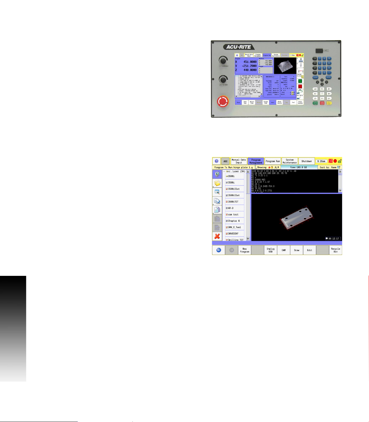
ACU-RITE conversational, and G-code formats
The ACU-RITE conversational programming format is a method of
writing programs; g-code (ISO) programming is also supported.
Preview graphics in the editors illustrate the individual machining
steps for programming the contour as well as the corresponding tool
path generated. If a production drawing is not dimensioned for NC
programming, the CAM can be used to graphically generate a
complete part program. Work piece machining can be graphically
simulated either during or before actual machining.
The conversational and g-code (ISO) formats are the same as that
used in previous CNC products (3000M, 5000M, 6000M and 6000i).
2 1 Introduction
Page 29
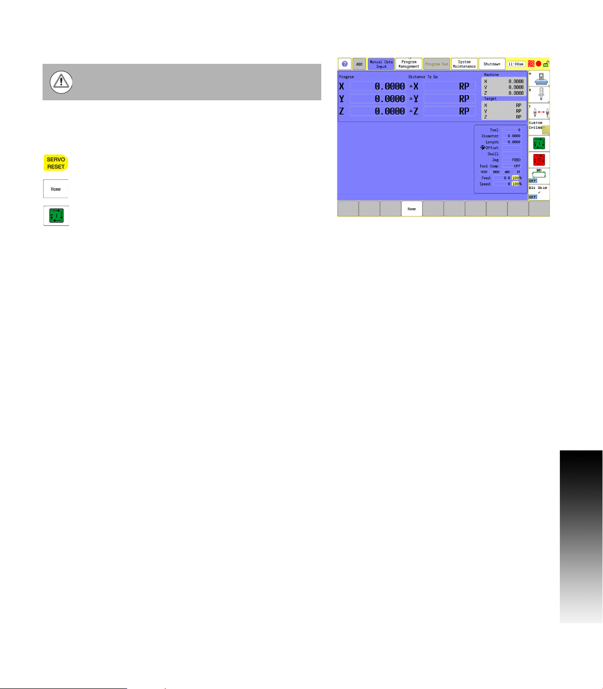
Powering Up the CNC Machine
When you power-on the CNC, ensure that the E-STOP
switch is in the in position.
Turn on the CNC machine according to the builder's instructions. Turn
the power switch on to the 3500i console.
The 3500i completely resets, activating the startup screen.
With the EMERGENCY STOP button out, reset the
servo drive by pressing the SERVO RESET key.
Press the Home button.
Press the Start button. The 3500i default display is
the Manual screen.
1.1 The 3500i
ACU-RITE 3500i 3
Page 30
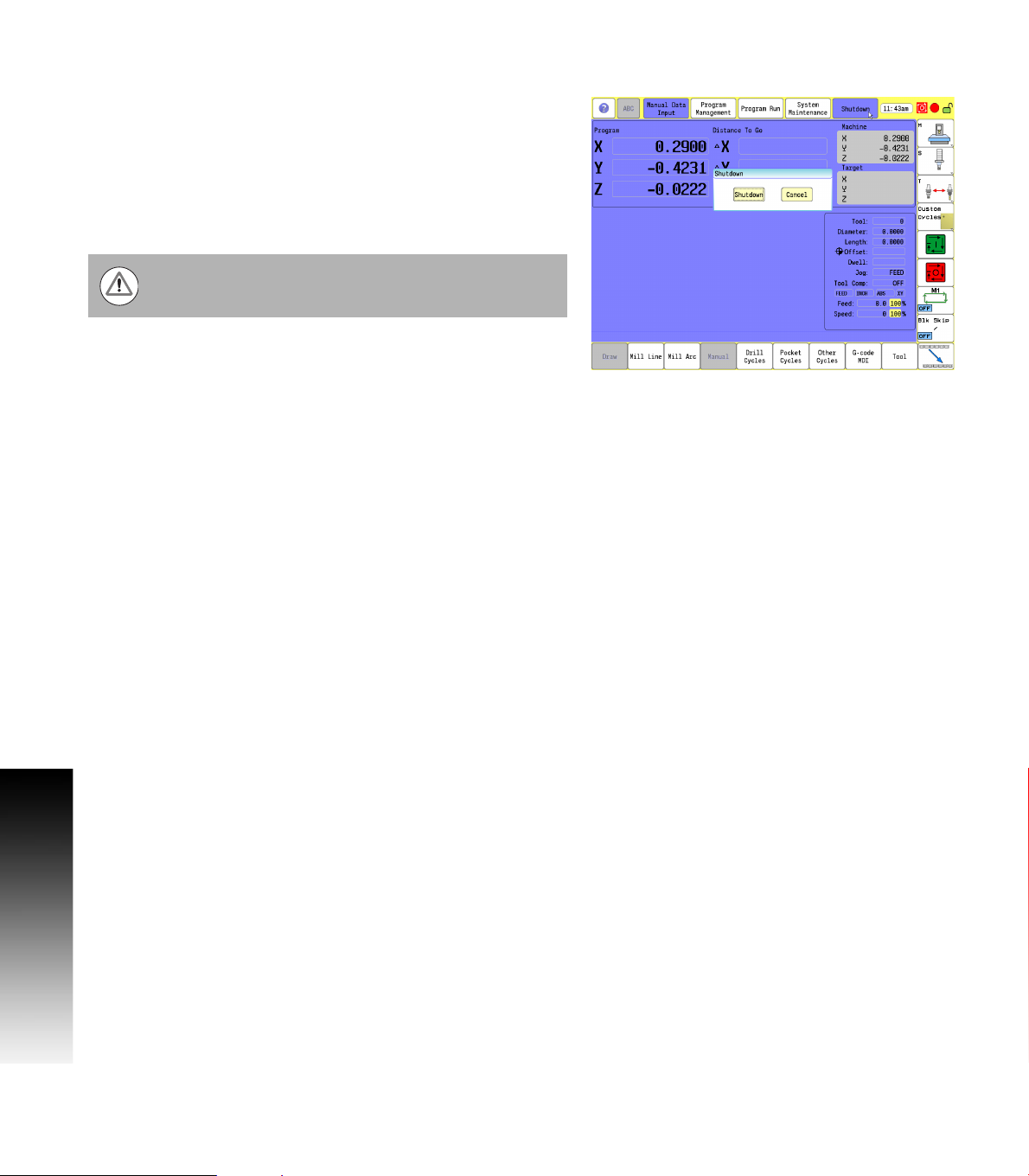
E-Stop, Servo Reset, and CNC Shutdown
Press E-STOP to disengage the servos and then revert to Manual
Data Input Mode.
Touch Shut Down to display the Shut Down dialogue. Touch Shut Down
to power down the CNC, or touch Cancel to cancel the shut down.
The shutdown takes less than a minute. The 3500i will let you know
when it is safe to turn power off. Or, you can touch Reboot (or press
1.1 The 3500i
the ENTER key) to re-start the 3500i.
Follow the builder's instructions for turning off the machine.
Always shutdown the CNC before turning power off to the
machine.
Emergency Stop (E-STOP)
Press E-STOP to take all axes and spindle servos offline. This ends all
machine movement.
To reset E-STOP, pull out and turn the rotary switch clockwise in the
direction of the arrows. The switch makes a touching sound when
it resets.
Resetting E-STOP does not automatically reactivate the servos.
Activating/Resetting the Servos
For safety reasons, the CNC powers up with the servomotors
disengaged. While the servos are off, the CNC cannot move the
machine.
Reset the servos as follows:
If a limit switch disengaged the servos, manually reposition the
machine inside its normal range of travel.
Press E-STOP to display the message External emergency stop
Rotate the E-STOP switch in the direction of the arrows to reset it.
Press SERVO RESET to reset the servos.
4 1 Introduction
Page 31

Writing Programs
The 3500i allows many features to be used without having to write a
program. But for operations that repeat or complex machining it is best
to write a program. Before you start to write a program, determine the
work-holding device and the location of Part Zero (the point to which
all movement is referenced). Since absolute positions are defined
from Part Zero, try to select a location that directly corresponds to
dimensions provided on the part print, such as the lower left corner of
the work. Then, you can develop a program using a procedure similar
to the one that follows:
The first block of a program is a safe starting position. This is where
the tool-change position (a location away from the work area where
the axes can return for safe tool changing) is input. The first block
includes the units of measurement (Inch/MM), mode of operation
(Absolute), move type (Rapid), and to cancel all auxiliary functions
(Tool Offsets, Spindle, and Coolant). This is the same as in g-code
(e.g. typical first blocks: G70, G90, G0, G28, Z0, & M5). Refer to
chapter 11 "G-Code on page 366”.
Subsequent blocks in the program set Spindle information, call Tool
number, turn on Coolant, and make the initial move toward the
work.
The remaining blocks in the program describe the required moves,
Canned Cycles, and Tool changes to complete the machining.
The next to the last block in the program returns the axes to the Tool
change position, turning off any auxiliary functions (Tool Offsets,
Spindle, and Coolant). The last block , EndMain, (M2) ends the
program. This is the same as in g-code (e.g. typical last blocks: M5,
G0, T0, X0, Y0, Z0, M9; M2). Refer to chapter 11 "M-Code List on
page 370”.
After writing a program, verify it. Run it in Draw Mode to troubleshoot
for errors. Verify that all programmed moves are safe, and accurate
to the part print dimensions.
Load the stock material into the selected work-holding device.
Set the Tool Offsets for each tool in the Tool Page.
Before running the part in the Auto Mode, run it in Single-Step Mode
to verify that both the program and the setting of Tool Offsets have
been correctly completed. Single-Step Mode allows you to execute
the program block-by-block.
After testing the program, make any necessary corrections.
When the finished program is ready for production, back it up on a
USB memory device.
1.1 The 3500i
ACU-RITE 3500i 5
Page 32

1.2 Visual Display Unit
Operating Panel with Touch Screen display
The ACU-RITE 3500i has a 12.1-inch Flat-Panel Color Touch Screen
Display. The following list of items are also located on the front panel.
See "Manual Data Input" on page 20 for mapping information of the
start up screen. For information regarding the Key pad, see "Console
Key Pad" on page 19.
The following features are located on the front panel of the ACU-RITE
3500i console:
1 Touch screen Flat Panel Color Display.
2 Numeric key pad, and Axis selection keys.
1.2 Visual Display Unit
3 Arrow keys
4 Axis Jog keys
5 Start, Stop, and Servo Reset keys
6 Emergency “E” Stop
7 Feed Rate override
8 Spindle Speed override
9 USB Port
Screen Navigation
The 3500i screens change as different modes are activated. Basic
procedures and features of the software remain the same, regardless
of the 3500i mode.
The 3500i console provides a touch screen operating panel. To
enter data, select a feature, or perform an action, momentarily touch
the corresponding button on the screen.
6 1 Introduction
Page 33

Menus, Dialogues, and Forms
This section describes general overview of the pop-up menus,
dialogues, and forms provided by the 3500i. Complete information is
provided in this manual where specific examples of actions are being
explained.
Pop-up menus allow you to make a selection from multiple options.
When a pop-up appears touch the desired selection or use the ARROW
keys and touch Enter.
Some features will require entering data in a form. Enter the required
data in the field; touching Enter moves to next field. When done touch
the Use button to have the 3500i accept the feature or touch the
Cancel button. Additional buttons may be present based on the form
being used.
Operator Prompts
Actions that require immediate data input to continue the operation,
the 3500i will prompt for the required information. The required data
can be entered with the on screen keyboard, and numeric keypad.
Cursor
The 3500i uses a cursor, or highlight to mark data field for selection or
editing. Touch the screen, or use the ARROWS to move the cursor, or
highlight. The cursor can be activated in a field that is highlighted by
touching the highlighted field, or using the left/right ARROW keys.
1.2 Visual Display Unit
ACU-RITE 3500i 7
Page 34

General Operating Guidelines
The following provides the general operating guidelines for the 3500i.
Mode specific function buttons are always located on the left
vertical edge of the screen.
Scroll bars automatically appear when the window information does
not completely fit into the current window size.
The active operating mode is highlighted in blue in the top menu bar.
The activated key in the side bar will highlight in blue also. More
than one key may be activated at a time depending on the action
being taken. Available selection keys for the current activity are
highlighted. Non-available keys are grayed out.
Use the Context Sensitive Help feature when assistance is desired.
This is an intuitive feature that aids the user by going directly to the
1.2 Visual Display Unit
section in the manual in relation to the feature, or button that you
select to obtain assistance with.
It is important to understand that this manual is written
with the assumption that the user is using the touch
screen.
A USB pointing device e.g. mouse, trackball, etc. may also
be used. If a device is being used, the action of clicking on
a screen key corresponds to the same action as if the user
is touching the screen. A USB keyboard can also be used.
Main Operating Modes
The ACU-RITE 3500i has three main operating modes: Manual Data
Input (MDI), Program Management, and Program Run. These are
accessed with the large rectangular buttons at the top of the screen.
Manual Data Input allows data input for simple machining
operations. Manual operation, single step operation, and single
commands can be entered. See "Manual Data Input Menu Bar" on
page 40 for a complete description.
8 1 Introduction
Page 35

Program Management provides access to existing programs for
running, simulating or editing. New programs can be created here
with access to the CAM, and Draw features. Programs can also be
copied to or from a USB memory device (like a memory stick or
thumb drive), or network. See "Accessing Program Management"
on page 88 for a complete description.
Program Run allows a selected program to either auto run without
pausing, or single step through a program as it is running. See
chapter "9.1 Running a program" on page 266 for a complete
description.
Sub Modes
Within the three main operating modes; Manual Data Input, Program
Management, and Program Run, there are sub-modes for each. The
Sub Modes are accessed via the horizontal menu bar along the bottom
of the touch screen.
Sub modes for Manual Data Input provide data input for machining
operations such as milling a line, an arc, engraving, drilling and
creating pockets. All these are accessed by filling the corresponding
form. Manual operation can also be done here. As well as access to
tool management and fixture offset tables. See "Manual Data Input
Menu Bar" on page 40 for a complete description. The 3500i
remembers all operations which can then easily be saved to a
program for later re-use. It is also possible to re-run a previous
operation without having to re-enter all the data.
Sub modes for Program Management provide access to edit
existing programs, or create a new program. The CAM, Draw
features can be accessed here where a program can be run in
simulation mode. If a program was accidentally deleted, it can be
recovered using the Recycle Bin. See "Accessing Program
Management" on page 88 for a complete description.
Sub modes for Program Run provide access to such actions as auto
run a program without pausing, or single step through a program,
and provide a drawing display of the machining taking place. It is also
possible to use all Program Management features while the
machine is running. See chapter "9.1 Running a program" on page
266 for a complete description.
1.2 Visual Display Unit
When a sub mode key is activated, it is not possible to
change to another main mode.
ACU-RITE 3500i 9
Page 36

Upper Menu and Status Information Bar
The 3500i display screen upper bar always remains the same
regardless of the operation or function that is being preformed, and
general status information. See "Manual Data Input" on page 20 for a
complete description of the screen layout.
1 Help button
ABC button to hide or unhide the on screen keyboard & numeric
2
keypad
3 Manual Data Input button
4 Program Management button
5 Program Run button
6 System Maintenance button
7 Shutdown button
8 Clock
1.2 Visual Display Unit
9 Program running status:
Red - Machine is idle
Green - System is running
10 Message Indicator:
Yellow/Red (flashing): Error or Warning
Green: All OK
11 Screen Lock: Touch Screen can be locked while a program is
running, or at anytime the operator chooses. Press the CLEAR key
on the keypad to unlock the touchscreen.
12 Message Bar: Messages will pop-up (e.g. an error or warning) and
can be cleared by touching the message bar. The message bar
appears in all modes, and sub-modes of operation.
10 1 Introduction
Page 37

Machine function buttons
Machine function buttons are always located on the right side of the
screen. They remain constant, and do not change regardless of the
current action the machine is performing. They provide an easy way
to perform supported machine functions. The actual features available
depend on the machine builder.
Buttons 1 through 4 have a small marker in the lower right hand
corner which indicates that more features (or sub menus) are
available when this button is touched.
Sub menus are dynamic, and change according to the type of
machine the 3500i is installed on.
1 Machine Menu
2 Spindle Menu
3 Tool Menu
4 Custom Cycle Menu
5 NC Start, same as the front panel NC Start key
6 NC Stop, same as the front panel NC Stop key
7 Toggle on or off Optional Stop feature
8 Toggle on or off Block Skip feature
1.2 Visual Display Unit
ACU-RITE 3500i 11
Page 38

Keyboard
An on screen QWERTY keyboard will automatically pop-up when you
enter a field that requires text information input.
The 3500i touch screen keyboard becomes visible (pop-up) when
text, and numerical information is required for an action that is
currently being taken.
When the information has been entered using the keyboard, and the
Use button has been touched, the keyboard will disappear from the
screen. The keyboard will also be removed from the screen when
the Cancel button is touched.
1.2 Visual Display Unit
The touch screen keyboard can be hidden to prevent it
from popping up if it is not required, e.g. a USB keyboard
is being used. Touch the ABC button to hide it. To display
the keyboard again after it has been hidden, touch the ABC
button at anytime when it has a white back ground. A gray
back ground indicates that the 3500i has disabled the
touch screen keyboard when it can not be used with the
current activity.
12 1 Introduction
Page 39

Additional Buttons
The following additional buttons are always available on the keyboard.
1 Enter Button, same as ENTER key.
2 Special Characters Button - shows other characters.
Copy Button - copy information in the current field to the copy
3
buffer.
Paste Button - paste previously copied information in the current
4
field.
5 Clear Button - clear the current field.
6 Shift Button - switch between upper and lower case.
7 Backspace Button - delete the character to the left of the cursor.
8 Drag Bar Use to move the keyboard to a different location.
Special Characters
The keyboard has a second “Special Characters” page provided which
is accessed by touching the “(#*\!” button 1.
Touching the “(#*\!” button displays the special character buttons.
Touching the button again returns to the main keyboard. The Copy,
Paste, Backspace, Enter, and Clear buttons are also displayed.
The touch screen keyboard state is not affected when
ever the console has a power cycle. If it was disabled prior
to a power cycle, it will remain disabled. The same applies
if it was activated, it will remain activated.
1.2 Visual Display Unit
ACU-RITE 3500i 13
Page 40

Programming Sliders
The following list describes the slider controls shown here.
1 Jump to the beginning
2 Page Up
3 Up Arrow
4 Scroll Bar
5 Arrow Down
6 Page Down
7 Jump to the end
8 Horizontal Bar
9 Window Slider
Scroll Bar(s) are used to scroll through the active window.
Window Slider(s) are used to resize a window on the screen.
1.2 Visual Display Unit
Scroll bars, and/or sliders are available in all screens that require
navigation assistance.
14 1 Introduction
Page 41

Numeric touch pad
An on screen numeric touch keypad will automatically pop-up when
you enter a field that requires numeric data input.
When information has been entered using the on screen numeric
keypad, touch the Enter button. The next field requiring data input
will be highlighted. When finished, touch the Use button to enter the
data, or touch the Cancel button to cancel out of the current
dialogue. Touching either button will remove the numeric touch pad
from the screen.
1 Copy button
2 Paste button
3 Clear button
4 Backspace button
5 Enter button.
6 Calculator On-Off Button
7 Drag Bar
1.2 Visual Display Unit
The on screen numeric touch keypad can be turned off to
prevent it from popping up if it is not required, e.g. a USB
keyboard is being used. Touch the ABC button to hide it.
To unhide the on screen numeric keypad, touch the ABC
button at anytime when it is highlighted.
The on screen numeric keypad is turned on by default
when ever the console has a power cycle.
ACU-RITE 3500i 15
Page 42

Calculator
The on screen numeric keypad has a built in calculator feature.
The 3500i on screen numeric touch pad calculator feature is
available whenever the on screen numeric keypad is open.
To open the calculator feature, touch the Calculator button.
1 Calculator button
2 Advanced Calculator button
3 Calculator result window
The calculator works like a normal handheld calculator. When using
the calculator touching = puts the result in the result window.
Touching Enter puts the result in the active field.
Advanced Function buttons
1.2 Visual Display Unit
When using the on screen numeric touch pad calculator feature
additional advanced function buttons are available.
Touch the advanced icon button SIN COS X
calculator features. Touch the advanced icon button SIN COS X
again to return to the basic calculator feature.
To close the calculator feature, touch the Calculator button to
return to the numeric keypad.
2
to access the advanced
2
16 1 Introduction
Page 43

Context Sensitive Help
The Acu-Rite 3500i uses an intuitive method to aid the user when
assistance is desired. When assistance is needed with a feature, the
User Manual can be displayed directly at the point which describes the
pertinent feature.
To use Help, as the example screen shows; the console is in Manual
Data Input, and a Linear Engraving cycle is being programed. It is
desired to see descriptions of the cycle parameters, and the cycle
itself. The following steps describe the actions the user needs to take.
Using Context Sensitive Help
To activate the user assistance, first press the Help
button.
This puts the control into the help selection mode.
At this time, touch the feature on the screen which you would like
assistance with.
This will display a new window containing the section in the User
Manual, opened directly to the description of the desired feature.
From there, you can also use the tree view on the left, or the
navigation buttons at the top, to navigate, and view other sections
of the User Manual.
To close the window and return to normal operation,
press the Exit button at the top of the window.
1.2 Visual Display Unit
ACU-RITE 3500i 17
Page 44

The following buttons are available when using Help.
Button Function
Help button activates the User Manual Help screen
window.
Back moves back through the current viewing
history.
Next moves forward through the current viewing
history.
Show/Hide Tree toggles the view of the left
tree-view section.
Maximize/Minimize toggles between window and
1.2 Visual Display Unit
full screen views.
Exit closes the User Manual help window, and
returns to current operating screen.
18 1 Introduction
Page 45

Console Key Pad
The following keys are located on the console key pad. There is also
a quick reference guide located at the beginning of this manual, see
"Controls of the 3500i" on page ii.
1 Axis keys, use to select the required axis.
2 Numeric keys, use to enter numeric data, included is the toggle
key for “Plus/Minus” data entry.
3 CLEAR key, use to clear selections such as values entered.
4 ENTER key, use to activate selections, and entries.
5 Arrow keys, use to navigate around the screen, and highlight
dialogue fields.
6 HAND key, use to cycle the CNC through manual movement
modes: RAPID JOG, JOG FEED, JOG @ 100, JOG @ 10, JOG @ 1.
7 Manual move (Jog) Axis keys, use to manually move (Jog) the
machine axis in the direction required.
8 SERVO RESET, use to activate servo motors.
9 STOP key, use to stop a program that is running, or a machine
operation. Same as Stop button in Machine function buttons.
10 START key, use to start a program to run, or a machine operation
previously stopped. Same as Start button in Machine function
buttons.
1.2 Visual Display Unit
ACU-RITE 3500i 19
Page 46

1.3 Main Operating Mode Screens
Display navigation
The three main operating modes: Manual Data Input, Program
Management, and Program Run each have there own screen. A
condensed description of these has been provided here on how to
navigate, become familiar with the information that is being provided.
Manual Data Input
The Manual Data Input screen (default screen), displays several
windows, and program buttons. The following list maps what is being
viewed on this screen. When the console is first turned on, the unit
defaults to this screen.
1 Manual Data Input (default screen).
Horizontal button Bar. These keys change to correspond with the
2
selected main mode display.
3 Display area / Preview Screen.
This displays the position of the machine during a program or
4
single event run.
5 This displays the Distance To Go per the program being run.
1.3 Main Operating Mode Screens
The Machine display window displays the actual position of the
6
machines axes.
The Target display window displays the position that the machine
7
is going to.
8 This displays the status of the machine during its current activity.
Machine function button; actual buttons displayed depend on the
9
features of your machine.
Program running status:
10
Red - Machine is idle.
Green - Program is running.
Message Indicator:
Yellow/Red (flashing): Error or Warning.
11
Green: All OK.
12 Screen Lock: The touch screen can be locked at any time.
20 1 Introduction
Page 47

Program Management Screen
The Program Management screen displays several windows, and
buttons. The following list maps what is being viewed on this screen.
See “Accessing Program Management” on page 88.
1 Program Management main mode button.
2 Program List window.
3 Program Text Preview area.
4 Program Display area.
5 Horizontal Button Bar.
Program Type Information Display, and available computing
6
space.
7 Program Sort Button.
8 Touch Program To Run button to select program.
Any button that has a second function (small gray dot in
lower left corner) is activated by touching it for two
seconds.
1.3 Main Operating Mode Screens
ACU-RITE 3500i 21
Page 48

Program Run
Select a program to run. Touch the Program Run button. The CNC loads
the program. The name of the currently loaded program is displayed in
the Program Name field at the center of the screen.
There are two modes of programed operation:
Single-Step Mode: Runs a program one block at a time. See “Using
Draw with running programs” on page 270.
Automatic Mode: Runs a program automatically, without pausing.
See “Auto mode” on page 266.
1 Program Run main mode button.
2 Single Step, and Auto buttons. Default is Auto.
3 Program display.
4 Program status display.
5 Manual button cancels the program.
Draw View
When Draw is activated, a display window opens. When the program
1.3 Main Operating Mode Screens
is started, the loaded tool movement, and the action it is taking is
displayed. See “Starting Draw” on page 257.
1 Draw button to view real time drawing.
2 View buttons to select view type.
3 Real time draw display.
22 1 Introduction
Page 49

1.4 Accessories:
Available accessories include a selection of electronic Touch Probes,
and Hand Wheels.
Touch probes
Touch Probe Function software option.
With the various HEIDENHAIN 3-D touch probe systems you can:
Automatically align work pieces
Quickly and precisely set datum
Measure the work piece during program run
Measure and inspect tools
TS 220, TS 640 and TS 440 touch trigger probes
These touch probes are particularly effective for automatic work piece
alignment, datum setting and work piece measurement. The TS 220
transmits the triggering signals to the CNC via cable and is a
cost-effective alternative for applications where digitizing is not
frequently required.
The TS 640 (see figure) and the smaller TS 440 feature infrared
transmission of the triggering signal to the CNC. This makes them
highly convenient for use on machines with automatic tool changers.
Principle of operation: HEIDENHAIN triggering touch probes feature a
wear resisting optical switch that generates an electrical signal as
soon as the stylus is deflected. This signal is transmitted to the
control, which stores the current position of the stylus as an actual
value.
1.4 Accessories:
ACU-RITE 3500i 23
Page 50

TT 140 tool touch probe for tool measurement
The TT 140 is a triggering 3-D touch probe for tool measurement and
inspection. Your CNC provides three cycles for this touch probe with
which you can measure the tool length and radius automatically either
with the spindle rotating or stopped. The TT 140 features a particularly
rugged design and a high degree of protection, which make it
insensitive to coolants. The triggering signal is generated by a
wear-resistant and highly reliable optical switch.
HR electronic hand wheels
1.4 Accessories:
Electronic hand wheels facilitate moving the axis slides precisely by
hand. A wide range of traverses per hand wheel revolution is available.
Apart from the HR 130 and HR 150 integral hand wheels,
HEIDENHAIN Corp. also offers the HR 410 portable hand wheel.
Electronic Edge Finder
The Electronic Edge Finder enables the ability to teach positions, find
the center point of a circle, or locate datum (work piece zero) by
touching off on the part. Advantage of an electronic edge finder is that
it instantly senses when contact is made with the point (even if the
axis over traveled).
24 1 Introduction
Page 51

Machining Fundamentals
Page 52

2.1 Fundamentals of Positioning
Position encoders and reference marks
The machine axes are equipped with position encoders that register
the positions of the machine table or tool. Linear axes are usually
equipped with linear encoders, rotary tables and tilting axes with angle
encoders.
When a machine axis moves, the corresponding position encoder
generates an electrical signal. The CNC evaluates this signal and
calculates the precise actual position of the machine axis.
If there is a power interruption, the calculated position will no longer
correspond to the actual position of the machine slide. To recover this
association, incremental position encoders are provided with
reference marks. The scales of the position encoders contain one or
more reference marks that transmit a signal to the CNC when they are
crossed over. From that signal the CNC can re-establish the
assignment of displayed positions to machine positions. For linear
encoders with distance-coded reference marks the machine axes
need to move by no more than 20 mm, for angle encoders by no more
than 20°.
2.1 Fundamentals of Positioning
With absolute encoders, an absolute position value is transmitted to
the control immediately upon switch-on. In this way the assignment
of the actual position to the machine slide position is re-established
directly after switch-on.
26 2 Machining Fundamentals
Page 53

Reference system
A reference system is required to define positions in a plane or in
space. The position data are always referenced to a predetermined
point and are described through coordinates.
The Cartesian coordinate system (a rectangular coordinate system) is
based on the three coordinate axes X, Y and Z. The axes are mutually
perpendicular and intersect at one point called the datum. A
coordinate identifies the distance from the datum in one of these
directions. A position in a plane is thus described through two
coordinates, and a position in space through three coordinates.
Coordinates that are referenced to the datum are referred to as
absolute coordinates. Relative coordinates are referenced to any other
known position (reference point) you define within the coordinate
system. Relative coordinate values are also referred to as incremental
coordinate values.
Reference system on milling machines
When using a milling machine, you orient tool movements to the
Cartesian coordinate system. The illustration at right shows how the
Cartesian coordinate system describes the machine axes. The figure
illustrates the right-hand rule for remembering the three axis
directions: the middle finger points in the positive direction of the tool
axis from the work piece toward the tool (the Z axis), the thumb points
in the positive X direction, and the index finger in the positive Y
direction.
The CNC 3500i can control 3 or 4 axes optionally. The 4th axis is
designated by the letter “U”. The “U” axis function depends on the
builder.
2.1 Fundamentals of Positioning
ACU-RITE 3500i 27
Page 54

Designation of the axes on milling machines
The X, Y and Z axes on your milling machine are also referred to as tool
axis, principal axis (1st axis) and minor axis (2nd axis). The assignment
of the tool axis is decisive for the assignment of the principal and
minor axes.
Tool axis Principal axis Minor axis
XYZ
YZX
ZXY
Polar coordinates
2.1 Fundamentals of Positioning
If the production drawing is dimensioned in Cartesian coordinates, you
also write the part program using Cartesian coordinates. For parts
containing circular arcs or angles it is often simpler to give the
dimensions in polar coordinates.
While the Cartesian coordinates X, Y and Z are three-dimensional and
can describe points in space, polar coordinates are two-dimensional
and describe points in a plane. Polar coordinates have their datum at a
circle center (CC), or pole. A position in a plane can be clearly defined
by the:
Polar Radius, the distance from the circle center CC to the position,
and the:
Polar Angle, the value of the angle between the reference axis and
the line that connects the circle center CC with the position.
28 2 Machining Fundamentals
Page 55
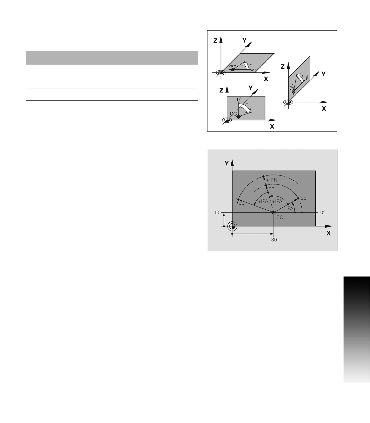
Setting the pole and the angle reference axis
The pole is set by entering two Cartesian coordinates in one of the
three planes. These coordinates also set the reference axis for the
polar angle PA.
Coordinates of the pole
(plane)
X/Y +X
Y/Z +Y
Z/X +Z
Absolute and incremental polar coordinates
Absolute polar coordinates always refer to the pole and the reference
axis.
Incremental coordinates always refer to the last programmed nominal
position of the tool.
Reference axis of the angle
2.1 Fundamentals of Positioning
ACU-RITE 3500i 29
Page 56

Angle Measurements
Polar measurement of angles is referenced from the 3 o'clock position
(0 degrees). Positive angles rotate in a counterclockwise direction;
negative angles rotate in a clockwise direction.
2.1 Fundamentals of Positioning
30 2 Machining Fundamentals
Page 57

Absolute and incremental work piece positions
Absolute work piece positions
Absolute coordinates are position coordinates that are referenced to
the datum of the coordinate system (origin). Each position on the work
piece is uniquely defined by its absolute coordinates.
Example 1: Holes dimensioned in absolute coordinates
Hole 1 Hole 2 Hole 3
X = 10 mm X = 30 mm X = 50 mm
Y = 10 mm Y = 20 mm Y = 30 mm
Incremental work piece positions
Incremental coordinates are referenced to the last programmed
nominal position of the tool, which serves as the relative (imaginary)
datum. When you write a part program in incremental coordinates,
you thus program the tool to move by the distance between the
previous and the subsequent nominal positions. Incremental
coordinates are therefore also referred to as chain dimensions.
Example 2: Holes dimensioned in incremental coordinates
Absolute coordinates of hole 4
X = 10 mm
Y = 10 mm
Hole 5, with respect to 4 Hole 6, with respect to 5
X = 20 mm X = 20 mm
Y = 10 mm Y = 10 mm
2.1 Fundamentals of Positioning
ACU-RITE 3500i 31
Page 58

Setting the datum
Fixture Offsets
A production drawing identifies a certain form element of the work
piece, usually a corner, as the absolute zero datum. When setting the
datum, you first align the work piece along the machine axes, and then
move the tool in each axis to a defined position relative to the work
piece. Set the display of the CNC either to zero or to a known position
value for each position. This establishes the reference system for the
work piece, which will be used for the CNC display and your part
program.
If the production drawing is not dimensioned for that particular CNC,
set the datum at a position or corner on the work piece which is
suitable for deducing the dimensions of the remaining work piece
positions.
The fastest, easiest and most accurate way of setting the datum is by
using a 3-D touch probe from HEIDENHAIN Corp. Refer to chapter "7.3
Probing Cycles on page 199”.
Example 1: Offset
See "Fixture Offset (Work Coordinate System Select):" on page 138 for
2.1 Fundamentals of Positioning
more information on using the Offset cycle. Use the Offset command
to apply a Fixture Offset of the absolute zero datum to the corner of
WorkPiece #1.
Format: Offset Fixture #1 X10 Y10
Offset Fixture #1
Machining positions are now referenced from the lower left corner of
WorkPiece #1.
Use the Offset command to apply a Fixture Offset of the absolute
zero datum to the corner of WorkPiece #2.
Format: Offset Fixture #2 X60 Y10
Offset Fixture #2
Machining positions are now referenced from the lower left corner of
WorkPiece #2.
32 2 Machining Fundamentals
Page 59

Example2: SetZero
See "Absolute Zero Set" on page 140 for more information on using the
SetZero cycle. The work piece drawing shows holes (1 to 4) whose
dimensions are shown with respect to an absolute datum with the
coordinates X=0 Y=0. Holes 5 to 7 are dimensioned with respect to a
relative datum with the absolute coordinates X=450, Y=750. With the
SetZero cycle you can temporarily set the datum to the position
X=450, Y=750, to be able to program holes 5 to 7 without further
calculations.
Format: SetZero X450 Y750
2.1 Fundamentals of Positioning
ACU-RITE 3500i 33
Page 60

2.2 Manual Machine Positioning
Jog Mode Moves
You can make or change jog moves when the CNC is in Manual Data
Input Mode, Teach Mode, or in the Tool Page; and the servos are on.
Jog Mode Description
Rapid Default rapid speed for continuous jogs. Actual
Feed Continuous jog at feedrate determined at machine
Jog: 100 Conventional Jog Mode, increment set to 100 times
speed determined at machine setup.
setup.
machine resolution.
Jog: 10 Conventional Jog Mode, increment set to 10 times
Jog: 1 Conventional Jog Mode, increment set to actual
machine resolution.
machine resolution.
2.2 Manual Machine Positioning
Changing the Jog Mode
Jog move modes, with the exception of Jog Rapid Mode, are
performed at the currently active feedrate. The CNC displays the
active Jog Mode in the Machine Status Display Area. See "Axis Jog
keys" on page 274.
In Manual Data Input Mode, Press the JOG key to select a jog feed
rate.
Pressing the JOG key continually cycles through the modes listed
above.
Incremental Moves
To make a jog increment move, press the JOG key to select a
Jog 100, Jog 10, or Jog 1 mode.
Press the Axis +/- keys for the desired axis to step the axis in the
corresponding direction at the designated resolution.
Continuous Moves
To manually position the machine using continuous movement,
press the JOG key to select either the Rapid or Feed Jog Modes.
Press the Axis +/- keys for the desired axis to move the axis in the
corresponding direction at the currently active feedrate (Feed Mode)
or at the machine rapid rate (Rapid Mode).
34 2 Machining Fundamentals
Page 61

Adjusting the Feedrate
The Feedrate Override rotary switch can be used to override the
currently active feedrate or rapid rate for machine moves. The switch
provides a range of 0% to 150%. Setting the switch to 100% will allow
the actual feedrate or rapid rate currently active to be used.
The machine builder determines the default rapid rate and
maximum feedrate at setup. If the CNC is shut down, the
configuration file reloads these default rates at the next
power-on.
Overriding the Spindle RPM
The SPINDLE Override rotary switch can be used to override the
currently active programmed spindle speed. The switch provides a
range of 5% to 120%. Setting the switch to 100% will allow the actual
spindle speed currently active to be used.
2.2 Manual Machine Positioning
ACU-RITE 3500i 35
Page 62

2.2 Manual Machine Positioning
36 2 Machining Fundamentals
Page 63

Manual Data Input
Page 64

3.1 Manual Data Input (MDI)
Overview
Manual Data Input allows data input for simple machining operations.
Manual operation, single step operation, and single commands can be
entered.
The following describes the concepts, and formats used with the
ACU-RITE 3500i CNC.
These topics are being introduced in this chapter.
Manual Data Input Screen
Manual Data Input Mode Settings
Manual Data Input
Manual Data Input Operations
Manual Data Input Cycles
Block History
3.1 Manual Data Input (MDI)
G-code MDI
MDI Touch Screen Feature Dialogues
MDI Teach
Manual Data Input Screen
The 3500i display screen provides the information required to monitor
the machine, it’s movement, programming, program management,
and much more.
The default screen, or home screen, displays several windows,
operating modes, and buttons. The following list maps what is being
viewed on this screen. When the console is first turned on, the unit
defaults to this screen. See Section 1, "Manual Data Input" on page 20.
1 Program Position.
2 Program Distance to go.
3 Machine: Actual Machine Position.
Target: Position Machine going to.
4 Secondary Dashboard: Current tool, Offset, Modals, and
Feed/Speed information.
38 3 Manual Data Input
Page 65

Manual Data Input Mode Settings
Features (or settings) that remain active for more than one operation
are referred to as modal. Modal features remain active until you
change or cancel them. Most CNC functions are modal.
As an example, if the CNC is in Rapid Mode, it executes all moves at
the rapid rate until you initiate Feed Mode. The CNC can be in several
modes, as long as the modes do not conflict.
Before making a manual move, make any necessary mode settings.
Modes set from the Manual screen remain active if the CNC is put in
a program mode until the program, or operator changes the mode.
Modes set from the Manual Data Input screen:
See "Basic Modals zone." on page 49.
Examples:
Absolute or Incremental
Rapid or Feed
Active tool, tool-length offsets, and tool diameter compensation
Inch or MM
Basic Modals (allowing adjustment of current modal settings)
3.1 Manual Data Input (MDI)
ACU-RITE 3500i 39
Page 66
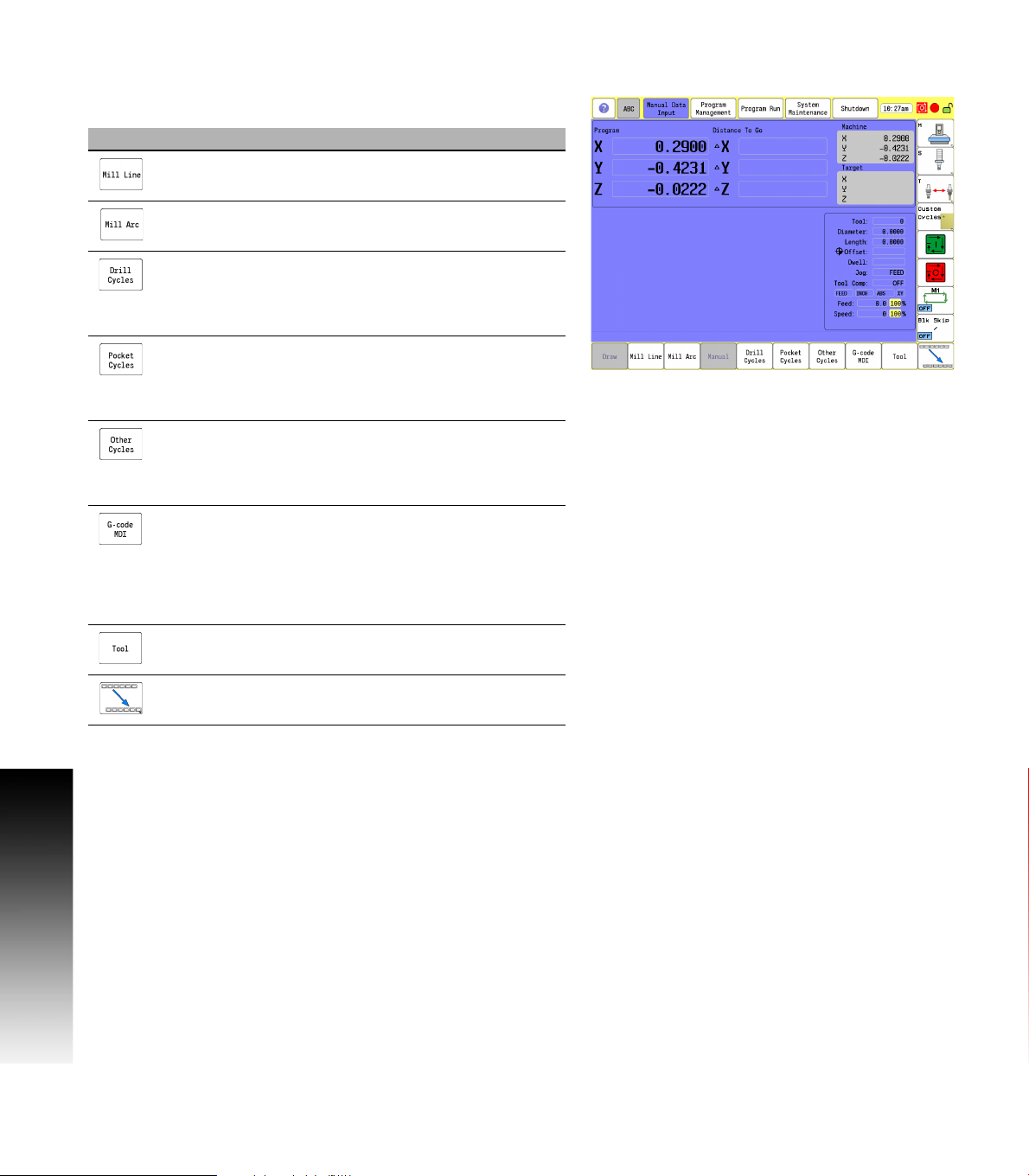
Manual Data Input Menu Bar
The following table describes the bottom bar menu buttons.
Button Function
Mill Line opens the Mill Line pop-up dialogue
where information can be entered to mill a line.
Mill Arc opens the Mill Arc pop-up dialogue where
information can be entered to mill an arc (or radius).
Drill Cycles opens a sub menu for selection of type
of drilling cycle, e.g. Basic, Pecking, Counter Bore
etc.). Selection of a cycle opens a form for data
input.
Pocket Cycles opens a sub menu for selection of
type of pocket cycle, e.g. Circular, Rectangular, Slot,
etc.). Selection of a cycle opens a form for data
input.
3.1 Manual Data Input (MDI)
Other Cycles opens a sub menu for selection of type
of other cycles, e.g. Face, Tool Probing, Linear
Engraving, etc.). Section of a cycle opens a form for
data input.
G-code MDI toggles the 3500i between standard
Manual Data Input, and G-code Manual Data Input
mode. The G-code MDI opens up a text editor for the
operator to allow single G-code commands to be
entered. Blocks are inserted for multiple machining
operations using the G-code, or ISO format.
Tool opens the Tool Table.
Touch the next menu button to activate the next
button bar.
40 3 Manual Data Input
Page 67

Draw & Manual bottom menu bar buttons.
Button Function
Touching the Draw button will view real time drawing
of the work piece as it is being machined.
Manual button when touched will cancel the
program.
MDI Menu Page two
The following table describes the bottom bar page two menu buttons.
Button Function
Record is used to toggle between recording all
Manual Data Input commands entered in standard
MDI. If record is on, all commands successfully run
will be recorded. If a command does not run
successfully, it will not be placed in the block history.
Save History saves Manual Data Input to a program.
Either standard MDI or G-code MDI, depending on
the current mode.
Clear History clears current history (deletes manual
data input). In standard MDI the block history is
deleted, and in G-code MDI the G-code editor
contents are deleted.
Block History list block history, and allows blocks to
be edited.
Teach opens the pop-up dialogue to create a new
program, or open an existing program for teach
purposes.
Remote Diagnose submits a service request using
the Remote Diagnostics feature.
Touch to return to default screen.
3.1 Manual Data Input (MDI)
ACU-RITE 3500i 41
Page 68
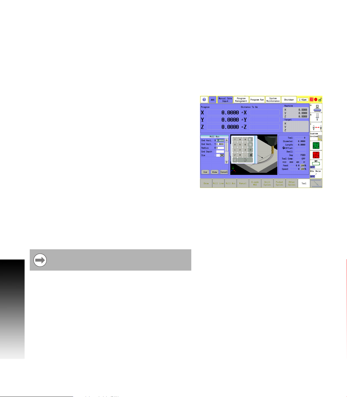
Manual Data Input Operations
The following explains a few of the machining operations that are
available with Manual Data Input. Examples have been provided to
explain an overview to the operator of the 3500i’s capabilities.
The Drill Cycles, Pocket Cycles, and Other Cycles buttons access
sub menus of different types of cycles that are available in each of
these categories.
A cycle, or operation is ran by pressing Use. While running a graphic
representation can be seen by touching the Draw button. The Manual
button can be touched at anytime to cancel an operation.
Mill Arc manual data input
From the bottom menu bar touch the Mill Arc button.
The touch screen displays a graphic of an arc milling operation, and
the highlight bar is positioned in the first field on the form that is
requiring data input.
The numeric pad is also displayed to enter data into the field. The
3.1 Manual Data Input (MDI)
Use button can be touched once all fields have been entered, or the
data input can be canceled at any time by touching the Cancel
button.
When the data has been entered, touch the Enter button on the
numeric pad.
The highlight bar will go to the next required field input, and the
graphic view changes to display graphically the next required data
input.
When the data has been entered, touch the Enter button again on
the numeric pad.
The above steps repeat for each data entry, and the display continues
to change, showing what is required for the data entry.
In addition to the required parameters, the More button can be
touched to show additional data entry inputs when this button is
available. The More button is not available on all menus.
The buttons Use, View, and Cancel are common to all
Manual Data Input forms.
42 3 Manual Data Input
Page 69

Mill Arc manual data input View
Touch the View button to view the Mill Arc data input graphically.
Touch the Exit button to return to the Mill Arc dialogue.
The view option is available with all manual data actions.
Touch the Use button to run the operation.
Touch the Start button to execute the machining cycle, or touch the
Manual button to cancel.
3.1 Manual Data Input (MDI)
ACU-RITE 3500i 43
Page 70

Manual Data Input Cycles
The MDI Cycles are grouped in three categories as described in the
following groups.
Drill Cycles
Basic
Pecking
CounterBore
Bi-Dir Bore
Uni-Dir Bore
Flat Bottom Bore
Tapping
Thread Mill
Chip Break
Pocket Cycles
Rectangular
3.1 Manual Data Input (MDI)
Circular
Frame
Ring
Hole
Slot
Circular Slot
Plunge Rectangular
Plunge Circular
Other Cycles
Face
Rectangular Profile
Circular Profile
Linear Engraving
Arc Engraving
Tool Probing: Length/Diameter, Length Special, Diameter Special,
Break/Wear, Probe Calibration.
Spindle Probing: Edge Find, Corner Out, Corner In, In/Out Boss,
In/Out Web. Probe Move, Skew Compensation, Probe Calibration.
44 3 Manual Data Input
Page 71

When a Cycles button is touched, the available cycles in that category
are listed.
Touch the name of the cycle that is to be executed by the machine
to display the manual data input form.
A full description of the above listed Cycles, and
programming applications are provided in this manual.
Refer to chapter 7 "Canned Cycles" on page 149.
Pocket Cycle Example
From the bottom menu bar touch the Pocket Cycles button.
Touch Rectangular in the sub menu.
The touch screen displays a graphic of a rectangular milling cycle,
and the highlight bar is positioned in the first field on the form that
is requiring data input.
The numeric pad is also displayed so that data can be entered into
the required fields that are shown. The Use button can be executed
once all fields have been entered, or the operation can be canceled
at any time by touching the Cancel button.
3.1 Manual Data Input (MDI)
Enter the data in each field for the pocket size and depth. Use the
Enter button on the numeric key pad to use the data entered in a
field, and move to the next field.
When the data has been entered, touch the Enter button on the
numeric pad.
The highlight bar will go to the next required field input, and the
graphic view changes to display graphically the next required data
input.
When the data has been entered, touch the Enter button again on
the numeric pad, or touch the More button to insert additional data.
ACU-RITE 3500i 45
Page 72

The More button is used to enter additional (or optional) parameters
regarding the machining of the pocket such as corner radius, side
finish stock, etc.
These additional parameters are not typically required.
To exit from the More Menu, touch the More button again. The
required parameters are displayed.
Rectangular Pocket Cycle data input View
Touch the View button to view the rectangular pocket data input
3.1 Manual Data Input (MDI)
graphically, and is useful for verification.
Touch the Exit button to return to the rectangular pocket dialogue.
The view option is available with all MDI forms.
Touch the Use button to run the operation, or Cancel to cancel the
operation.
After touching the Use button, the 3500i will prompt you to touch
the Start button to run the operation, or the Manual button to
cancel. Draw can be activated while running to provide a graphical
representation of the operation while machining.
A full description of Pocket Cycles, and programming
applications are described in the chapter “Canned
Cycles”. Pocket Cycles can be found on page 171.
46 3 Manual Data Input
Page 73

Block History
The MDI block history allows the operator to record all cycles that are
programmed into the MDI to be retrieved or saved into a part program.
By default the recording of the MDI cycles is on and can be turned off
by toggling the Record button on the second set of menu bar MDI
buttons.
This block history can be cleared by touching the Clear History button
on the second set of menu bar buttons or saved into a part program
by touching the Save History button. When saving the history, the
operator is given the option to save it as a G-code/ISO program or
Conversational.
To view the current history, touch the Block History button on the
second set of menu bar MDI buttons.
From within this dialog individual cycles can be deleted by highlighting
the cycle in the list and touching the Delete button. The cycle form can
also be opened again for re-edit. Select a cycle, and/or re-run a cycle
by touching the Select button. Once the cycle form is brought back
up the operator can then follow the same procedure as the previous
section for running the cycle. Touch Close to exit the Block History
dialogue.
3.1 Manual Data Input (MDI)
ACU-RITE 3500i 47
Page 74

G-code MDI
The ACU-RITE 3500i also has G-code Manual Data Input mode, and
allows you to command moves without creating a part program. MDI
also is a quick way to program one move, or a series of moves that are
used only one time. Refer to chapter 11 "G-Code Program Editing" on
page 352.
To enter G-code MDI mode, use the G-code MDI button on the bottom
menu bar.
Type an instruction on the command line of the Program Area, and
touch START. In Manual Mode, the cursor rests on the command line.
More than one command can be programmed at a time. Use a
semicolon (;) to separate the commands.
Touch HOLD to pause one-shot moves.
Touch START to continue. MDI moves are executed only once. To recall
a previously commanded block, touch UP ARROW or DOWN ARROW to go to
the line that you want. You can execute from any line on the MDI
history page. After you execute, the CNC takes you to the top line of
3.1 Manual Data Input (MDI)
the history page. You can store up to 150 lines on the MDI history
page.
Clear History and Save History are on the second menu bar. Clear
History will allow the contents of the G-code MDI window to be
cleared. Save History will allow the contents of the window to be
saved to a G-code/ISO format part program file.
You must know the location of the Absolute Zero before
making Absolute Mode moves.
48 3 Manual Data Input
Page 75

MDI Touch Screen Feature Dialogues
The 3500i allows the operator to do quick machine functions directly
from the Manual Data Input screen. Touching on any of these marked
touch screen zones opens a dialogue for data input. The data entered
only affects the manual operation of the control, it does not affect the
automatic Program Run mode.
Depending on where the screen is touched within each
“Zone”, the dialogue will open defaulting to the item that
was touched within the zone. As an example; touch the
Y axis in the X, Y, Z zone, and the dialogue opens with the
Y axis selected in the dialogue.
Touch Screen Zones
1 Zero Axes zone.
2 Preset Axes zone.
3 Target Location zone.
4 Tool zone.
5 Offset zone.
6 Basic Modals zone.
7 Feed and Speed zone.
Zero Axes
Touching the X, Y, & Z zone opens the Zero Axes dialogue, allowing
the operator to zero one or more axes.
Touch the X, Y, and Z zone, or select an axis in the zone by touching
that axis.
The Zero Axes dialogue opens, and the axis that was touched is
automatically selected. An X will appear in the box next to the
selected axes.
Touching a selected axis again will unselect that axis.
Touch Use to zero the selected axes, or touch Cancel to exit without
making any changes.
When the Use button has been selected, the operator will be
prompted to “touch Start to run operation or Manual to cancel”.
Touch the Start button to execute the change, or:
3.1 Manual Data Input (MDI)
Touch the Manual button to cancel all changes.
ACU-RITE 3500i 49
Page 76

Program Preset
Touching the numerical values in the Preset Axes zone opens the
Program Preset dialogue, allowing the operator to preset one or more
axes.
Touch the Preset Axes zone, or select an axis in the zone by
touching that axes numerical value.
The Program Preset dialogue opens, and the axis that was touched
is automatically selected. The cursor will appear in the data entry
field next to the selected axes.
Enter the preset position values for each axis that is to be defined.
Touch Use to enter the data, or touch Cancel to exit without making
any changes.
When the Use button has been selected, the operator will be
prompted to “Press Start to run operation or Manual to cancel”.
Press the Start button to execute the change, or:
3.1 Manual Data Input (MDI)
Touch the Manual button to cancel all changes.
50 3 Manual Data Input
Page 77

Move to Target Location
Touching in the Target location zone opens the Move to Target
Location dialogue, allowing the operator to move one or more axes to
a specific location.
The operator can enter position locations for the active axes, feed rate
(value or Rapid) and absolute or incremental positioning. If the feed
rate is not specified, the 3500i will use the last programmed feed rate.
If the "From Machine Home" checkbox is checked, the positions are
moved from the home position of each axes.
Touch the Target Location zone, or select an axis in the zone by
touching that axis.
The Move to Target Location dialogue opens, and the axis that was
touched is automatically selected. The cursor will appear in the data
entry field next to the selected axes.
Enter the position location values for each axis that is to be defined.
Touch Use to enter the values, or press Cancel to exit without
making any changes.
When the Use button has been selected, the operator will be
prompted to “Press Start to run operation or Manual to cancel”.
Press the Start button to execute the change, or:
Touch the Manual button to cancel all changes.
3.1 Manual Data Input (MDI)
ACU-RITE 3500i 51
Page 78

Tool
The tool dialogue allows the operator to temporarily adjust tool
settings or mount a new tool. If only a tool number is entered, the
system will mount the tool, and use the values stored in the tool table.
If any of the other values are entered (e.g. diameter, length, etc) the
tool settings for the tool number provided will be modified. The new
values will not be stored in the tool table as they are temporary manual
settings.
Touch the Tool Location zone.
The Tool dialogue opens. If a Tool has not been selected, the cursor
will appear in the Tool entry field. When a tool was previously
selected, then the cursor will be present in the data entry field that
was touched (e.g. Diameter, length).
To clear the current tool, touch the Clear Tool Offsets button.
Enter the data required for the tool.
Touch Use to enter the values, or press Cancel to exit without
making any changes.
When the Use button has been selected, the operator will be
3.1 Manual Data Input (MDI)
prompted to “Press Start to run operation or Manual to cancel”.
Press the Start button to execute the change, or:
Touch the Manual button to cancel all changes.
52 3 Manual Data Input
Page 79

Offset
Offset allows the operator to activate a new offset from the Offset
table, or modify existing values in the Offset table.
If only a fixture offset number is entered, the system will activate the
offset provided from the offset table. If any of the other values are
entered (e.g. X, Y, Z, etc.) the offset settings for the fixture offset
number will be modified and the new values are stored in the offset
table.
Touch the Offset Location zone to open the Offset dialogue.
To deactivate the current fixture offset, touch the Clear Fixture
Offsets button.
To use an existing Fixture Offset, enter the Offset number from the
table in the data field.
Modify any of the values (e.g. X, Y, Z, etc.) in the data field if
necessary, new values will update the current values in the Offset
table.
Touch Use to enter the values, or press Cancel to exit without
making any changes.
When the Use button has been selected, the operator will be
prompted to “Press Start to run operation or Manual to cancel”.
Press the Start button to execute the change, or:
Touch the Manual button to cancel all changes.
3.1 Manual Data Input (MDI)
ACU-RITE 3500i 53
Page 80

Basic Modals
Basic Modals allow the operator to set some of the basic modals for
the system. In this dialog, the operator is allowed to adjust the current
modal settings of the system (plane, absolute/incremental, inch/mm
and rapid/feed mode).
Touch the Basic Modals Location zone.
The Basic Modals dialogue opens.
Adjust the current modal settings of the system by touching on
fields that require adjustment.
Touch Use to enter the changes, or press Cancel to exit without
making any changes.
When the Use button has been selected, the operator will be
prompted to “Press Start to run operation or Manual to cancel”.
Press the Start button to execute the change, or:
Touch the Manual button to cancel all changes.
3.1 Manual Data Input (MDI)
54 3 Manual Data Input
Page 81

Feed and Speed
This allows the operator to adjust the current feed and speed. There
are two modes for this, each having it’s own dialogue. When the
current active tool has values entered for the feed and speeds in the
tool table the “Feed and Speed Calculator” dialogue will open.
This dialogue allows the operator to use the feed and speed values as
is from the Feed and Speed tool table. The operator can also manually
enter new values or adjust the feed depending on a new speed value
entered.
Touch the Feed and Speed Location zone.
This example describes the Feed and Speed Calculator dialogue
showing the current active tool having values entered for the feed
and speed in the tool table.
First, select the type of operation that is to executed in the Type field
drop down menu.
To adjust the values directly, check the Enter New Values check box
and enter new values for Speed or Feed by touching the activated
edit fields and entering new values.
To adjust the Feed by entering a new Speed value, check the Enter
New Values check box.
Touch the activated Speed edit field, and enter the new speed value.
Touch the Update Feedrate button.
The new feedrate will be calculated using this new speed value as
will as the other parameters shown (e.g. tool diamenter, chip load,
and number of teeth).
Touch Use to activate the changes, or press Cancel to exit without
changing the active feed and speed.
When the Use button is touched, the operator will be prompted to
“Press Start to run operation or Manual to cancel”.
Press the Start button to execute the change, or:
3.1 Manual Data Input (MDI)
Touch the Manual button to cancel all changes.
See "Feeds & Speeds Overview" on page 68.
ACU-RITE 3500i 55
Page 82

When the current tool has no values entered into the Feed and Speed
table the Feed and Speed dialogue will be opened.
Touch the Feed and Speed Location zone.
The Feed and Speed dialogue opens.
To adjust the values directly, enter a new value in the Feed, and/or
Speed fields.
Touch Use to activate the changes, or press Cancel to exit without
making any changes.
When the Use button is touched, the operator will be prompted to
“Press Start to run operation or Manual to cancel”.
Press the Start button to execute the change, or:
Touch the Manual button to cancel all changes.
3.1 Manual Data Input (MDI)
56 3 Manual Data Input
Page 83

MDI Teach
The 3500i MDI also has a Teach mode which allows the operator to be
able to manually move the machine and record the positions to be
stored into a part program for running. The machine can be manually
moved by using the Jog buttons on the control. See "Jog Mode
Moves" on page 34.
To enter MDI Teach use the Teach button on the second set of menu
bar buttons. This will bring up a dialogue where the operator can
select an existing program, or create a new part program to store the
positions.
From within the Teach Program file select dialogue. The operator has
the option to select a previous part program by navigating to the
particular part program to highlight it and touch Ok to accept, or touch
the New Program to allow the operator to create a new part program
to store the information. Once the new part program is created the Ok
button can be used to enter Teach mode with this new program.
3.1 Manual Data Input (MDI)
ACU-RITE 3500i 57
Page 84

Once in Teach mode, the operator can use the control jog keys to
move the machine to the desired locations and then use the menu bar
buttons to create the commands to be saved.
Button Function
Rapid creates a rapid move using the current
position.
Line creates a line move using the current position.
Modal creates a modal using the last programmed
move command and the current position.
Delete Block will delete the highlighted block.
Quit will quit Teach mode without saving.
3.1 Manual Data Input (MDI)
Exit will exit Teach mode, saving the part program.
58 3 Manual Data Input
Page 85

Tool Management
Page 86

4.1 Tool Table
Tool Table / Tool Management
When the CNC executes a program block that activates a tool number,
the values on that row of the Tool Table are activated.
Tool Table values are automatically converted to their inch or
millimeter equivalents when the 3500i mode is changed. All typed
4.1 Tool Table
values must match the current unit mode of the 3500i.
The Tool Table is the only place where the 3500i converts
values from Inch to MM, or MM to Inch. Programmed
positions are not converted when the unit mode has been
changed.
Define and store up to 100 tools on the tool table. Type of data stored
on the tool table is information specific to each tool e.g. tool number,
diameter, length offset, tool type, etc.
The Tool Table is used by all machining programs.
Tool Compensation Required Data
You usually program the coordinates of path contours as they are
dimensioned in the work piece drawing. To allow the CNC to calculate
the tool center path, e.g. the tool compensation, you must also enter
the length and diameter of each tool you are using.
Tool data can be entered either directly in the part program with or
separately in the Tool Table. In the Tool Table, you can also enter
additional data for the specific tool. The CNC will consider all the data
entered for the tool when running the part program.
60 4 Tool Management
Page 87

Tool numbers / Tool names
Each tool is identified by a number between 0 and 100. The tool name
is its tool number. The machine builder determines the number of
tools available.
The tool number 0 is automatically defined as the zero tool (empty
spindle) with the length L=0 and the diameter D=0.
Sign for the length difference ΔL
If the tool is longer than the T1 tool: ΔL>0(+).
If the tool is shorter than the T1 tool:ΔL<0(–).
The tool length offset may be entered as a known value, or the 3500i
may determine the offset automatically. To have the 3500i determine
a tools length offset involves touching the tip of each tool to the part’s
Z0 surface, and touching the Teach button. This provides information
to the 3500i to determine the tool length offset for each tool. For more
detailed information, see "Tool-Length Offsets" on page 73.
Tool Diameter “D”.
Enter the tool diameter ”D” directly.
4.1 Tool Table
Locating the Tool Table
The Tool Table is accessed from the Manual Data Input screen.
To activate the tool table, touch the Manual Data
Input button (also referred to as a tab key).
In the bottom menu bar, touch the Tool button to
open the tool table.
ACU-RITE 3500i 61
Page 88

Editing the tool table
With the tool table open, it can now be edited by changing existing
information, or adding a new tools information.
Find the required tool by using the arrow keys, and/or scroll bars.
Touch the desired field to make changes.
Type in a new value, and touch the Enter button, or touch another
field.
4.1 Tool Table
The bottom bar menus are described on the following
pages.
Tool Table Menu Bar
The following is a description the lower menu bar buttons available.
Button Function
Tools button when activated displays the tool table
showing all tools that have been programmed into
the 3500i.
Fixture Offsets opens the offset table for data
entry. Up to 100 fixture offsets can be stored on the
table.
Feeds & Speeds opens the table where data can be
entered for each tool in the tool table when in Tool
mode. Certain fields will be calculated by the 3500i
based on the data input (e.g. Number of Teeth +
Surface Speed, and Spindle Speed in calculated).
Adjust opens the dialogue to adjust the current data
of a tool in any column that is highlighted.
Teach uses the current machine position for the
selected tool.
Use opens the dialogue Use Feature which asks if
you would like the current selected tool (or Fixture
Offset if in Fixture Offset mode) to be activated.
Touch the next menu button to activate the next
button bar.
Exit closes the Tool Table.
62 4 Tool Management
Page 89

Second Menu Bar
The following is a description the lower menu bar page two buttons
that are also available.
Button Function
Touch Find to locate a line in the tool table, or find
the tool or offset according to the value.
Clear Line clears the current line where the cursor
is located.
Clear Table clears the complete table.
Touch Teach Program to use the program position for
the selected tool.
Touch Clear Feature to clear the selected tool, or
fixture offset depending on the mode of the table.
Touch to return to the previous menu.
Copy To SIM copies the current Tool and Fixture
Offset tables to the Simulation Tool and Fixture
Offset tables and overwrites all data.
Copy From SIM copies from the Simulation Tool and
Fixture Offset tables and overwrites the current
data.
The Sim Tool and Sim Offset tables are only accessible
when the feature is enabled in the configuration. See
"Simulation Tool and Offset Tables" on page 71.
To use the numeric pad in the on screen menu, note the following:
Use the numeric keys to enter the required data. Use the Back Space
or Clear button to delete previously entered data.
Press the Enter button to save the data entered in the field.
4.1 Tool Table
ACU-RITE 3500i 63
Page 90

Clearing an entire line of tool data
All data pertaining to a tool number can be removed at once.
Select the tool number.
Touch the Next Menu button in the lower tool bar.
Touch the Clear Line button to remove all data.
4.1 Tool Table
Clearing the current tool table
All data pertaining to a tool number can be removed at once.
Touch the Next Menu button in the lower tool bar.
Touch the Clear Table button to remove all data.
64 4 Tool Management
Page 91

Find
The Find button provides a search of the Tool Table using either the
Tool number, or text. Searching for text is case sensitive. As an
example; if searching for end mill, but the text was inserted in upper
case letters “END MILL”, Find will only search for lower case text.
Touch the Find button to locate a tool number, and
enter the Line #.
Touch the Ok button to go to that line.
Finding a tool using text
Touch the Find button.
Touch the Find in Table button. The Find in Table
dialogue with keyboard is displayed.
Type in the text to be searched for keeping in mind that the search
criteria is case sensitive.
Touch the Ok button to locate the text.
4.1 Tool Table
ACU-RITE 3500i 65
Page 92

Clear Feature
The Clear Feature button is available in the Tool Table, and also in the
Fixture Offsets feature. In the Tool Table feature, it’s application is not
the same as in the Fixture Offsets feature. The following description
is for the Tool Table feature.
Select the Clear Feature button to clear the active
tool, and reset to T0.
Teach, and Teach Program
4.1 Tool Table
The Teach, and Teach Program buttons are used to automatically
provide position value for the selected tool depending on the button
used. Teach will use the machine position values and Teach Program
will use the program position values.
The Teach, and Teach Program buttons can be swapped so that one of
the two is located on the main Tool Table button bar and the other is
placed in the second menu bar.
To swap these button locations enter the Configuration and go to
UserSetup->CfgTooltableSettings->mainTeachSoftkey.
The value selected here is the button that shows up in the main menu
bar. Refer to the Technical Manual for more information for changing
configuration settings.
Select the Teach Program button to automatically
provide the data from the program position.
Select the Teach button to automatically provide the
data from the machine position.
When a W Axis knee scale is coupled with the Z Axis, the
Teach Program button should always be used. In this
scenario, set the mainTeachSoftkey configuration
parameter to Teach Program.
66 4 Tool Management
Page 93

Tool Table Structure
Tool table: Standard tool data
Column Description
Tool Number by which the tool is called in the
program (e.g. tool 2 = T2).
Diameter Compensation value for the tool diameter.
Length Compensation value for tool length.
D. Wear Tool diameter wear value.
L. wear Tool length wear value.
Type Tool type: A pop-up dialogue appears where
you can select the type of tool being used.
Comment Option to make a comment, or notation
regarding the tool that does not affect the
program.
Time1 Maximum tool life in minutes. This function
can vary depending on the individual machine
tool. Your machine manual provides more
information.
Time2 Maximum tool life in minutes during Tool
Call: If the current tool age exceeds this
value, the CNC changes the tool during the
next Tool Call (see also Cur_time).
Cur_Time Current age of the tool in minutes: The CNC
automatically counts the current tool life
(CUR_TIME). A starting value can be entered
for used tools.
4.1 Tool Table
TL Permissible deviation from tool length L for
RT Permissible deviation from tool diameter for
Max Length Maximum length of tool to be used for
Plunge Angle Angle of plunge cut.
ACU-RITE 3500i 67
wear detection. If the entered value is
exceeded, the CNC locks the tool (status L).
Input range: 0 to 0.9999 mm.
wear detection. If the entered value is
exceeded, the CNC locks the tool (status L).
Input range: 0 to 0.9999 mm.
roughing cycle. Default 0.
Page 94

Feeds & Speeds Table
Feeds & Speeds Overview
The Feeds & Speeds Table allows the user to enter additional tool data
for each tool so that the control can calculate Feeds and Speeds to be
used in MDI (Feed and Speed MDI Touch Screen Feature Dialog) or
programs. Based on the Tool Diameter and Tool Length as well as
other entered tool parameters the Spindle Speed, Rough Feed and
Finish Feed can be automatically calculated for each tool. For more
4.1 Tool Table
information on the Feed and Speed Calculator in MDI see page 55.
Feeds & Speeds Table Structure
The Feeds & Speeds Table can be accessed from the Manual Data
Input screen.
Touch the Tool button in the bottom menu bar.
Touch the Feeds & Speeds button to open the table.
68 4 Tool Management
Page 95

Data can be entered based on the Tool Diameter and Tool Length as
well as other entered tool parameters the Spindle Speed, Rough Feed
and Finish Feed can be automatically calculated for each tool in the
Tool Table.
Column Description
Tool Number Number of the tool corresponding to the Tool
Table.
Tool Diameter Compensation value for the tool diameter
(from Tool Table).
Tool Length Compensation value for tool length (from Tool
Table).
4.1 Tool Table
Number of
Teeth
Surface Speed Maximum surface speed of the tool.
Spindle Speed Calculated value for recommended Spindle
ChipLoad
(Rough)
Feed (Rough) Calculated value for recommended roughing
ChipLoad
(Finish)
Feed (Finish) Calculated value for recommended finish feed
The diameter and length in the Feeds and Speeds table
come from the Tool table. Changing them in the Feeds
and Speeds table will also update the Tool table.
Number of physical teeth on the tool.
Speed (calculated using the tool diameter and
surface speed).
Rough chip load of the tool.
feed (calculated using the tool diameter,
surface speed, rough chip load and number of
teeth).
Finish chip load of the tool.
(calculated using the tool diameter, surface
speed, finish chip load and number of teeth).
ACU-RITE 3500i 69
Page 96

Using the Feeds & Speeds Table
The 3500i can calculate spindle speed, rough feed and finish feed for
each tool.
To calculate the spindle speed enter the tool's diameter and the
desired surface speed. The initial diameter shown is from the tool
table. Changing the diameter in the Feeds & Speeds table also
changes it in the Tool.
The surface speed is in feet/min in inch mode or meters/min in
4.1 Tool Table
metric mode.
The calculated spindle speed is shown for the entered surface
speed.
The spindle speed in inch mode is calculated using:
rpm=surfaceSpeed*12÷(*toolDiameter). For example, with a tool
diameter of 0.5" and surface speed of 250 ft/min the resulting
spindle speed is 1910 (RPM).
The spindle speed in metric mode is calculated using:
rpm=surfaceSpeed*1000÷(*toolDiameter)
Feedrates can be calculated once the Spindle Speed is known.
Enter the number of teeth for the tool and a desired chip load for
roughing and finishing.
The corresponding feedrate is calculated for each chip-load.
The feedrate is calculated using:
feedrate = spindleSpeed * numberOfTeeth * chipLoad. For
example, with the previously calculated spindle speed, a 4 tooth tool
and chipload of 0.007 the resulting feedrate is 53.4 (in/min).
The calculated spindle speed can be overridden. In this case the
feedrate calculations use the new value. The calculated feedrates can
also be overwritten.
After doing all the needed feeds and speeds calculation, touch the
USE button to save changes, or CANCEL to exit without saving. In both
cases the Feeds and Speeds table closes.
70 4 Tool Management
Page 97

Simulation Tool and Offset Tables
The 3500i includes the advanced ability to utilize a second set of the
tool and offset tables, which apply only to Simulation mode. This
allows a user to create and simulate programs in the background while
running another program in the NC Program Run mode, without any
interference between the two modes.
The Simulation Tool Table and Offset Table are structured and behave
the same as the regular NC tables. When this feature is enabled,
additional soft key buttons are available for accessing and altering the
Simulation tables in Preview mode in the Editor and in Simulation
Draw. When this feature is disabled, the buttons are not available.
When this feature is enabled, programs being running in Simulation
mode will utilize these special Simulation tables, and thus will appear
to behave exactly the same as they would in Program Run mode.
Write operations within Tool Call blocks and Offset definition blocks
will be applied and saved to the Simulation tables, just as they would
normally do in Program Run mode with the NC tables. There are also
features available which allow the user to copy the data from the
Simulation tables to the NC tables, and vice versa.
When this feature is disabled, programs in Simulation mode will
instead retrieve the tool and offset data from the standard NC tables.
In order to eliminate the possibility of a simulated program altering the
NC tables, all write operations in Simulation mode are ignored, such
as the "H"/"UpdTable" parameter in the Tool Call block. In this context,
programs being simulated must have all tool and offset data defined
within the program, or all tool and offset data previously entered into
the NC tables prior to entering Simulation mode.
By default, this feature is disabled. The use of the Simulation tables
can be enabled/disabled in the configuration, via the entry
"useSimTables" under the section UserSetup -> CfgTooltableSettings.
4.1 Tool Table
ACU-RITE 3500i 71
Page 98

4.2 Tool Data
T-Codes, and Tool Activation
To activate a tool, program a T-Code followed by the tool number. The
tool number corresponds to the row number in the Tool Table. A
program tool call example starts with a “T”, followed by the tool
number, e.g. “T1”.
4.2 Tool Data
Activating Offsets via the Program
In a program, T1 (by itself) calls the Tool Table diameter and length
offsets for the specified tool. T1 with D, R, and L address words
programs a temporary diameter/radius and length offset independent
of the Tool Table. The entered D (diameter) or R (radius) and L
(tool-length) offsets remain active until you cancel the active tool.
T1 Format Description
T1 Activates Tool #1 diameter offset listed
in the Tool Table.
T1 D.5000 L-1.2500 Applies a diameter offset of .5000 and
T1 R.2500 L-1.2500 Applies a tool radius value of .2500 and
The diameter offset takes effect when you program Left (G41) or Right
(G42). All dimensions are in reference to the work surface.
If you use T1 to activate a tool later in the program, the
Tool Table offsets for Tool #1 are used (not the values
programmed via T1 Dn/Rn Ln).
It is recommended that you use the Tool Table to avoid
confusion or possible entry errors on the offsets.
length offset of -1.2500 to the active
tool.
length offset of -1.2500 to the active
tool.
72 4 Tool Management
Page 99

Tool-Length Offsets
Tool-length offset is the distance from Z0 Machine Home to the tip of
the tool at the part Z0 (the surface of the work).
Tool-length offsets allow each tool used in the part program to be
referenced to the part surface. In an idle state, the CNC does not have
a tool-length offset active. Therefore, Tool #0 (T0) is active. When T0
is active, all Z dimensions are in reference to the Z Home position.
When you program T1, all Z dimensions become referenced to the
surface on which the tool-length offset of Tool #1 was activated.
For machines that do not have a Z-axis automatic homing feature, you
must set the Z0 position of the Z-axis. Usually, it is the fully retracted
(Up) position of the quill or machine head. Tool-Length Offsets are
referenced to this position.
Because tools differ in length, Z0 axis (Part Zero) is not set the same
way as X0 or Y0. The tool-length offset is the distance from the tip of
the tool to the top of the part. Enter a length offset for each tool in the
Tool Table.
With tool-length offsets active, the Z-axis position display reads 0.00
when the active tool moves to Part Zero. Tool-length offsets simplify
programming.
Entering Tool Length Offsets in the Tool Table
As described previously, see "Locating the Tool Table" on page 61, the
tool table is accessed from the Manual Data Input screen.
The Tool Length Offset data is placed in the “Length” column in the
tool table.
To activate the tool table, touch the Manual Data
Input button.
In the bottom menu bar, touch the Tool button to
open the tool table.
With the tool table open, it can now be edited.
Select the tool number that is to be edited.
Use the scroll bars, or arrow keys to highlight the “Length” column
field.
Press the Enter key to activate the field.
Use the Back Space or Clear button to delete previously entered
data if necessary.
4.2 Tool Data
ACU-RITE 3500i 73
Page 100

With the tool in the spindle, carefully jog the tool down until it
touches the top surface of the work piece. This is referred to as
“Part Zero”.
Touch the Teach button. The 3500i calculates the tool
length offset for the selected tool putting the data to
the length column.
Press the Enter button to save the data entered in the field.
4.2 Tool Data
Diameter Offset in Tool Table
When you activate a tool, you automatically activate the length offset
and diameter values recorded on the Tool Table. When a tool is
activated, the length offset is applied immediately to provide an
accurate Z-axis position display.
The active diameter value is important when you program
compensated moves and use cycles with built-in tool compensation.
If tool diameter is correct, compensated moves and cycles are
executed accurately.
Enter tool-length offsets and tool diameter values on the numbered
lines of the Tool Table. The numbered lines on the Tool Table identify
the tool number (T-Code) that activates those values.
You can program a tool activation as a separate block or include it
within the block for most moves and cycles. Tool activation's
programmed, as separate blocks are easier to find in a Program
Listing.
The Tool Table can store information for up to a number of tools
specified by the machine builder.
On machines equipped with collet-type tool holders, it is impractical to
use the Tool Table to store tool-length offsets. You can set tool-length
offset at tool change. Tool Table diameters are still required for
compensated moves and when using cycles that have built-in
compensation. You can run all Jog features from the Tool Table.
Tool Table offsets activate when you program a T-Code.
74 4 Tool Management
 Loading...