

Acer ACERMATE 800 Annexe 1

& K DSWHU
System Board
The V12LC is a high-performance Pentium PCI-based system board
that supports the 64-bit Pentium microprocessor running at
75/90/100/120/133/150 MHz and has a 16-KB internal write-back
cache. It utilizes the Peripheral Component Interconnect (PCI) local
bus architecture. The PCI local bus maximizes the system
performance by enabling high-speed peripherals to m atch the speed
of the microprocessor with its 120 MB or 132 MB per second transfer
rate in burst mode.
The system board features a s lot for the PCI/ISA slot board and two
PCI enhanced IDE interfaces with a zero-wait state 11 MB per second
transfer rate and support up to four IDE devices. It has buff ered serial
ports that reduce the number of interrupts to avoid slowing other
system activities. With the optional ECP/EPP function, the parallel
port transfers data at a fast 2 MB to 10 MB.
The system board has two DRAM banks composed of four 72-pin
sockets that support both single- and double-density SIMMs for a
maxi mum memory of 128 MB.
System Board 1-1

1.1 Major Features
The system board has the following major features:
Pentium 75/90/100/120/133/150 MHz CPU in a zero-insertion
•
force (ZIF) socket
Two DRAM banks composed of four 72-pin SIMM sockets that
•
support 4/8/16/32-MB 60/70ns SIMMs
16-KB internal cache and 256-KB write-back second-level cache
•
128-KB Flash ROM for system and VGA BIOS
•
Two PCI enhanced IDE interfaces that support up to four IDE
•
devices
System clock/calendar with 128 bytes CMOS RAM
•
Cirrus 5430/5434/5440 VGA PCI accelerator that suppor ts up to
•
2-MB video memory for a resolution up to 1280x1024 with 256
colors non-interlaced or 1024x768 with 65,536 colors interlaced
External ports:
•
PS/2 keyboard/mouse ports
•
Two buffered high-speed serial ports
•
One ECP/EPP high-speed parallel port
•
Video port
•
Feature socket for multimedia or Ethernet solution (optional)
•
RJ-45 phone jack (optional)
•
1-2 User’s Guide
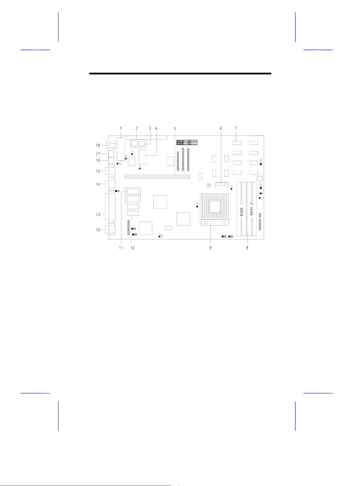
1.1.1 Layout
Figure 1-1 shows the locations of the system board major
components.
1 Keyboard controller
2 Feature socket for multimedia
or Ethernet solution (optional)
3 Flash memory BIOS
4 Real-time clock
5 Slot board connector
6 Voltage regulator
7 Second-level cache
8 SIMM sockets
9 320-pin ZIF CPU socket
10 Video memory chips
11 Video memory upgrade sockets
12 Video port
13 Parallel port
14 COM2
15 COM1
16 PS/2 Mouse connector
17 PS/2 keyboard connector
18 RJ-45 phone jack (optional)
Figure 1-1 System Board Layout
System Board 1-3
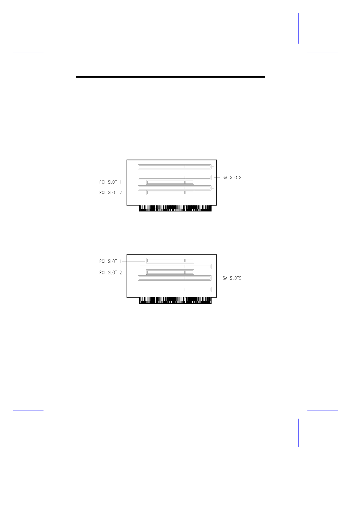
1.1.2 Slot Board
The system board comes with a slot board already installed. The slot
board carries the PCI and ISA bus slots for system enhanc ements and
future expansion.
The slot board may vary in size and layout depending on your system
housing. Figures 1-2 to 1-5 show the four kinds of slot boards.
Figure 1-2 2-PCI/3-ISA Slot Board (for generic desktop systems)
Figure 1-3 2 -PCI/3-ISA Slot Board (for Aspire desktop systems)
1-4 User’s Guide
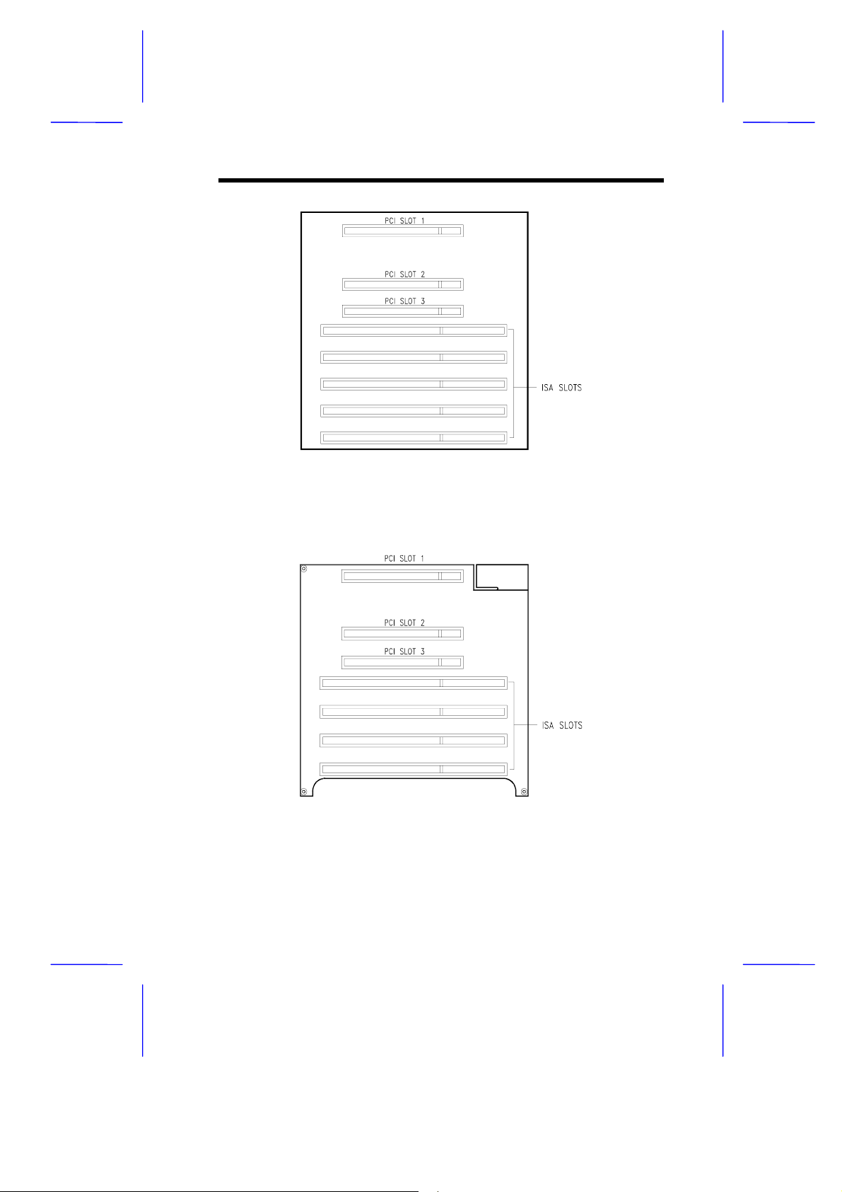
Figure 1-4 3-PCI/5-ISA Slot Board
(for generic mini-tower systems)
Figure 1-5 3-PCI/4-ISA Slot Board
(for Aspire mini-tower systems)
System Board 1-5
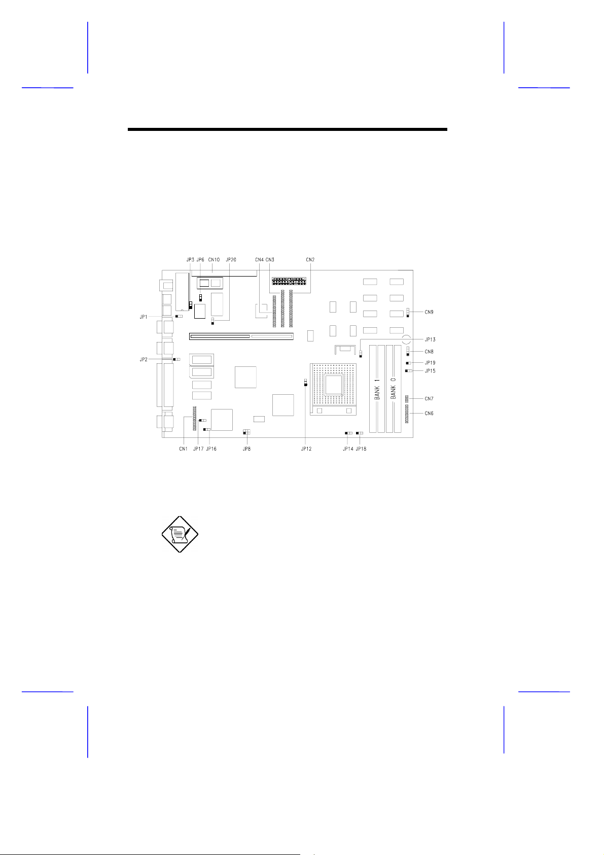
1.2 Jumpers and Connectors
1.2.1 Jumper and Connector Locations
Figure 1-6 shows the jumper and connector locations on the s ystem
board.
Figure 1-6 System Board Jumper and Connector Locations
Jumpers are prefixed “JP”. Connectors are
prefixed “CN”.
The blackened pin of a jumper represents
pin 1.
1-6 User’s Guide
 Loading...