

ABUS TVIP62560 operation manual

TVIP11561 / TVIP21560 / TVIP41560 /
TVIP42560 / TVIP61560 / TVIP62560
User guide
You can find important information and FAQs about this and other
products online at:
www.abus.com
Version 1.1
Firmware: 5.4.5 Build 171123
English translation of the original German user manual.
Retain for future reference.
English
Introduction
Dear Customer,
Thank you for purchasing this product.
ABUS Securit y-Center hereby decl ares that the TVIP11561 , TVIP21560, TVIP 41560, TVIP42560,
TVIP61560 and TVIP62560 cameras comp ly with the RED Directive 2014/53 /EU. These devices
also meet the requirements of the following EU directiv es: EMC Directive 2014/30/EU and t he
RoHS Directive 2011/65/EU. The full EU Declaration of Conformity text may be found at:
www.abus.com/product/TVIP11561
www.abus.com/product/TVIP21560
www.abus.com/product/TVIP41560
www.abus.com/product/TVIP42560
www.abus.com/product/TVIP61560
www.abus.com/product/TVIP62560
To ensure this con dition is maintained and that safe operation is guarant eed, it is your ob ligation to
observe this user manual.
Please read the entire user manual carefully before putting the product into operation, and pay attention
to all operating instructions and safety information.
All company names and product descriptions are trademarks of the corresponding owner. All
rights reserved.
If you have any questions, please contact your specialist installation contractor or specialist
dealer.
Data storage is subject to national data privacy guidelines.
Warning as required by §201 StGB (German Criminal Code):
Whosoever unlawfully makes an audio recording of the privately spoken words of another, and uses
or makes a recording thus produced accessible to a third party, shall be liable to imprisonment or a
fine.
Whosoever unlawfully overhears with an eavesdropping device the privately spoken words of
another not intended for his attention, or publicly communicates, verbatim or the essential content
of, the privately spoken words of another, recorded or overheard, shall incur the same penalty.
Disclaimer
This user manual has be en produc ed with the gre atest of care. S hould you disc over an y omiss ions
or inaccuracies, please contact us in writing at the address provided above.
ABUS Security-Center GmbH does not accept any liability for technical and typographical errors, and
reserves the right to m ake changes to the product a nd user manuals at an y time and without prior
warning.
ABUS Security-Center GmbH is n ot li ab le or r es p ons ible f or dir ec t or indirect da mage resulting from
the equipment, perf ormance a nd use of this product. No guarantee is made f or the co ntents of this
document.
2
English
The triangular high voltage symbol is used to warn of the risk of injury or health
We cannot be held liable for material or personal damage caused by improper
Explanation of symbols
hazards (e.g. caused by electric shock).
The triangular warning symbol indi ca tes i mportant note s in this us er manual which
must be observed.
This symbol indicates special tips an d n otes on the operation of the device.
Lists
1. …
2. …
• …
• …
Lists with a set order, given either in the text or warning notice
Lists without a set order, given either in the text or warning notice
Intended use
Use the device on ly for the purp ose for which it was built and des igned. An y other us e is considere d
unintended.
Important safet y information
General
Before using this de vice for the first tim e, pleas e read t he follow ing instruct ions car efully and o bserve
all warning information, even if you are familiar with the use of electronic devices.
All guarantee claims are invalid in the event of damage caused by non-compliance
with this user manual. We cannot be hel d liable for resulting damage.
operation or non-compliance with the safety information. All guarantee claims are
void in such cases.
Retain this handbook for future reference.
If you sell or pass on the device to third parties, you must include these instructions with the device.
The following safety information and hazard notes are not only intended to protect your health, but also
to protect the device from damage. Please read the following points carefully:
3

English
Power supply
• Only operate this device through a power source which supplies the mains power specified on
the type plate. If you are unsure of the power supply available to you, contact your energy
provider.
• Disconnect the device from the power supply before carrying out maintenance or installation
work.
• The device is only fully disconnected from the mains network when the power supply unit is
removed.
• To fully disconnect the device completely from the mains, the mains plug must be withdrawn
from the mains socket.
• In order to eliminate the risk of fire, the device's mains plug should always be disconnected from
the mains socket, if the device is not being used for an extended period of time.
Overload/overvoltage
• Prior to unstable weather and/or when there is a risk of lightning strike, disconnect the device
from the mains network or connect the device to a UPS.
• Avoid overloading electrical sockets, extension cables and adapters, as this can result in fire or
electric shock.
Cable
• Always grasp all cables by the plug connector and do not pull the cable itself.
• Never grasp the power cable with wet hands, as this can cause a short circuit or electric shock.
• Do not place the device itself, items of furniture or other heavy objects on the cable and ensure
that it does not become kinked, especially at the connector plug and at the connection sockets.
• Never tie a knot in the cable and do not bundle it together with other cables.
• All cables should be laid so that they cannot be trodden on, or cause a hazard.
• Damaged power cables can cause fire or electric shock. Check the power cable from time to
time.
• Do not modify or manipulate the power cable or plug.
• Only use adapter plugs or extension cables that conform to applicable safety standards, and do
not interfere with the mains or power cables.
Children
• Keep electrical devices out of reach of children. Never allow children to use electrical devices
unsupervised. Children may not always properly identify possible hazards. Small parts may be
fatal if swallowed.
• Keep packaging film away from children. There is a risk of suffocation.
• This device is not intended for children. If used incorrectly, parts under spring tension may fly out
and cause injury to children (e.g. to eyes).
Surveillance
• The use of surveillance equipment may be forbidden or regulated by law in some countries.
• Before using this equipment, ensure that all of your surveillance activities are completely legal.
4
English
Installation location/operati ng environment
Do not place any heavy objects on the device.
The device is only design ed for operation in spaces with appropr iate temperatures or humidity (e.g.
bathrooms), or excessive accumulation of dust. Please refer to the individual devices' technical data for
more detailed information.
Ensure that:
• adequate ventilation is always guaranteed (do not place the device on a shelf, thick carpet, bed
or wherever ventilation slits may be covered. Always leave a 10 cm gap on all sides)
• no direct sources of heat (e.g. radiators) can affect the device
• interior devices are not exposed to direct sunlight or strong artificial light
• the device is not in the immediate vicinity of magnetic fields (e.g. loudspeakers)
• no naked lights (e.g. lit candles) are on, or next to the device
• sprayed or dripping water is prevented from coming into contact with interior devices and caustic
fluids are avoided
• the device is not operated in the vicinity of water, in particular, the device should never be
submerged (do not place objects containing fluids, e.g. vases or drinks, on or near the device)
• no foreign bodies penetrate the device
• the device is not exposed to wide temperature variations, as otherwise there may be
condensation from humidity causing electrical short circuits
• the device is not exposed to excessive shock or vibration.
Unpacking the device
Handle the device with extreme care when unpacking it.
Packaging and packaging aids can be reused and, as far as possible, should be sent for recycling.
We recommend the following:
Paper, cardboard and corrugated cardboard as well as plastic packaging items should be placed in the
appropriate recycling containers.
If no such facility exists in the area, these materials should be put into the general household waste.
Disposal
Warning
If the original pack aging has been dam aged, start by inspect ing the de vice. If the device
shows signs of damage, return it in the original packaging and inform the delivery service.
Devices displaying this sym bol ma y not be disposed of with domes tic waste. At the end
of its service life, dispose of the product according to the applicable legal requirements.
Please contact your dea ler or dispose of the products at t he local collection point for
electronic waste.
5
English
Start-up
• Observe all safety and operating instructions before operating the device for the first time.
Warning
When installing the device in an existing video surveillance system, ensure that all devices
have been disconnected from the mains power circuit and low-voltage circuit.
Warning
Improper or unprofessional work on the mains network or domestic installations puts both
you and others at risk.
Connect the installations so that the mains power circuit and low-voltage circuit always run
separately from each other. They should not be connected at any point or become
connected as a result of a malfunction.
Care and maintenance
Maintenance is necessary if the device has been damaged (e.g. damage to the power cable and plug,
or the housing), or if liquids or for eign bodies have go t into the in terior of the d evice, or if it h as been
exposed to rain or damp, or if it does not work properly or has been dropped.
Maintenance
• If smoke, unusual noises or smells develop, switch the device off immediately and unplug from
the socket. In such cases, the device should not be used until it has been inspected by a
qualified technician.
• Have all maintenance tasks carried out by qualified technicians only.
• Never open the housing on the device or accessories unless this is necessary. As there is
always a risk to life due to electric shock when the housing is open, only open the housing when
the device is disconnected from the power source.
With some devices, opening the device is unavoidable and permitted for the following purposes:
• Installing the device
• Inserting a storage medium (SD card or hard disk drive)
• Accessing essential functions (reset button or WPS button)
Cleaning
• Only clean the device housing with a damp cloth.
• Do not use solvents, white spirit, thinners etc. or any of the following substances:
Brine, insect spray, solvents containing chlorine or acids (ammonium chloride), or scouring
powder.
• Rub the surface gently with the cotton cloth until it is completely dry.
The device operates with a dangerous voltage level. When conducting maintena nce
or cleaning work, disconnect the device from the mains.
6

English
Contents
1. Scope of delivery ................................................................................................................................. 9
2. Description of hardware ..................................................................................................................... 10
2.1. TVIP11561 ................................................................................................................................. 10
2.2. TVIP21560 ................................................................................................................................. 10
2.3. TVIP41560 / TVIP42560 ............................................................................................................ 11
2.4. TVIP61560 / TVIP62560 ............................................................................................................ 11
3. Description of hardware functions ..................................................................................................... 13
3.1. Status LEDs ............................................................................................................................... 13
3.2. Reset .......................................................................................................................................... 14
3.3. WPS ........................................................................................................................................... 14
3.4. Alarm input/output ...................................................................................................................... 14
4. Mounting/installation .......................................................................................................................... 15
4.1. TVIP11561 ................................................................................................................................. 15
4.2. TVIP21560 ................................................................................................................................. 15
4.3. TVIP41560 / TVIP42560 ............................................................................................................ 16
4.4. TVIP61560 / TVIP62560 ............................................................................................................ 16
5. Initial start-up ..................................................................................................................................... 17
6. First access........................................................................................................................................ 18
6.1. First access with ABUS IP Installer ............................................................................................ 18
6.2. Password assignment - Activation ............................................................................................. 18
6.3. Login ........................................................................................................................................... 19
6.4. Video plug-in .............................................................................................................................. 19
7. Live view ............................................................................................................................................ 20
7.1. Menu bar .................................................................................................................................... 20
7.2. Live view – buttons ..................................................................................................................... 21
7.3. Live view – PTZ control .............................................................................................................. 22
8. Help page .......................................................................................................................................... 22
9. Info page ............................................................................................................................................ 23
9.1. System status ............................................................................................................................. 23
10. Setup wizard .................................................................................................................................... 24
11. Advanced camera settings .............................................................................................................. 25
11.1. Video ........................................................................................................................................ 25
11.1.1. Image ................................................................................................................................. 26
11.1.2. Privacy mask ...................................................................................................................... 27
11.1.3. Video stream settings ......................................................................................................... 28
11.2. Network .................................................................................................................................... 29
11.2.1. IPv4/IPv6 ............................................................................................................................ 30
11.2.2. Port ..................................................................................................................................... 31
11.2.3. DDNS ................................................................................................................................. 31
11.2.4. FTP ..................................................................................................................................... 32
11.2.5. Wi-Fi ................................................................................................................................... 33
7

English
11.2.6. UPnP .................................................................................................................................. 34
11.2.7. SMTP / e-mail ..................................................................................................................... 34
11.2.8. NAT .................................................................................................................................... 35
11.2.9. HTTPS ................................................................................................................................ 35
11.3. Security .................................................................................................................................... 36
11.3.1. IP Address Filter ................................................................................................................. 37
11.3.2. Authentication ..................................................................................................................... 37
11.3.3. Security Service ................................................................................................................. 37
11.4. Text .......................................................................................................................................... 38
11.5. Date & time............................................................................................................................... 39
11.6. System ..................................................................................................................................... 40
11.6.1. General ............................................................................................................................... 41
11.6.2. Firmware/restart ................................................................................................................. 41
11.6.3. Log file ................................................................................................................................ 42
11.7. PTZ ........................................................................................................................................... 43
11.7.1. Preset / Tour / Pattern ........................................................................................................ 44
11.8. Event ........................................................................................................................................ 45
11.8.1. Motion detection ................................................................................................................. 46
11.8.2. Alarm input ......................................................................................................................... 47
11.8.3. Alarm output ....................................................................................................................... 47
11.8.4. PIR Alarm ........................................................................................................................... 48
11.9. Alarm manager ......................................................................................................................... 49
11.9.1. Add / edit alarm rule ........................................................................................................... 50
11.10. Storage ................................................................................................................................... 51
11.10.1. Record Schedule .............................................................................................................. 52
11.10.2. Storage Managem ent ....................................................................................................... 53
11.10.3. NAS .................................................................................................................................. 54
11.10.4. Snapshot .......................................................................................................................... 55
11.11. Audio ...................................................................................................................................... 56
11.12. User ........................................................................................................................................ 57
11.13. Local Configuration ................................................................................................................ 58
11.14. Playback ................................................................................................................................. 59
11.14.1. Playback time management ............................................................................................. 59
11.14.2. Playback operations ......................................................................................................... 60
8

English
1. Scope of delivery
TVIP11561
• Wi-Fi 1080p indoor camera with alarm
function
• Mount
• Power supply unit (EU, AU, UK)
• 1 m network cable
• CD
• Quickstart guide
• Installation materials
TVIP41560
• Wi-Fi HD 720p outdoor dome camera
• Power supply unit (EU, AU, UK)
• 1 m network cable
• CD
• Quickstart guide
• Installation materials
TVIP61560
• Wi-Fi HD 720p Outdoor Camera
• Power supply unit (EU, AU, UK)
• 1 m network cable
• CD
• Quickstart guide
• Installation materials
TVIP21560
• Wi-Fi 720p pan/tilt indoor camera with
alarm function
• Ceiling bracket
• Power supply unit (EU, AU, UK)
• 1 m network cable
• CD
• Quickstart guide
• Installation materials
TVIP42560
• Wi-Fi HD 1080p outdoor dome camera
• Power supply unit (EU, AU, UK)
• 1 m network cable
• CD
• Quickstart guide
• Installation materials
TVIP62560
• Wi-Fi HD 1080p Outdoor Camera
• Power supply unit (EU, AU, UK)
• 1 m network cable
• CD
• Quickstart guide
• Installation materials
9
English
2. Description of hardware
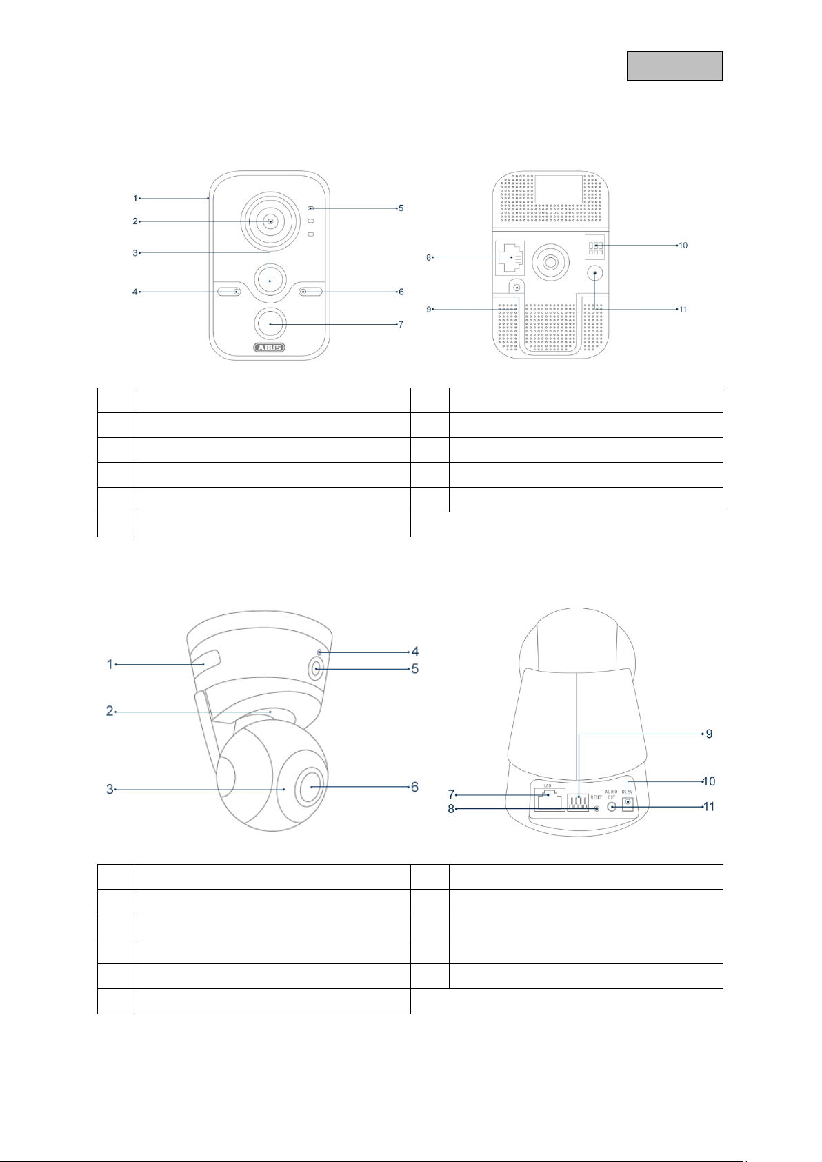
2.1. TVIP11561
1 microSD card slot 2 Lens
3 PIR – Passive Infrared Sensor 4 Microphone
5 Status LEDs 6 Photo sensor
7 IR LED 8 LAN (PoE-enabled)
9 WPS/Reset button 10 Alarm input/output
11 12 V DC power supply connection
2.2. TVIP21560
1 WPS button & microSD card slot 2 LED status bar
3 IR LEDs 4 Microphone
5 PIR – Passive Infrared Sensor 6 Lens
7 LAN 8 Reset button
9 Alarm input/output 10 5 V DC power supply connection
11 Audio output
10
English
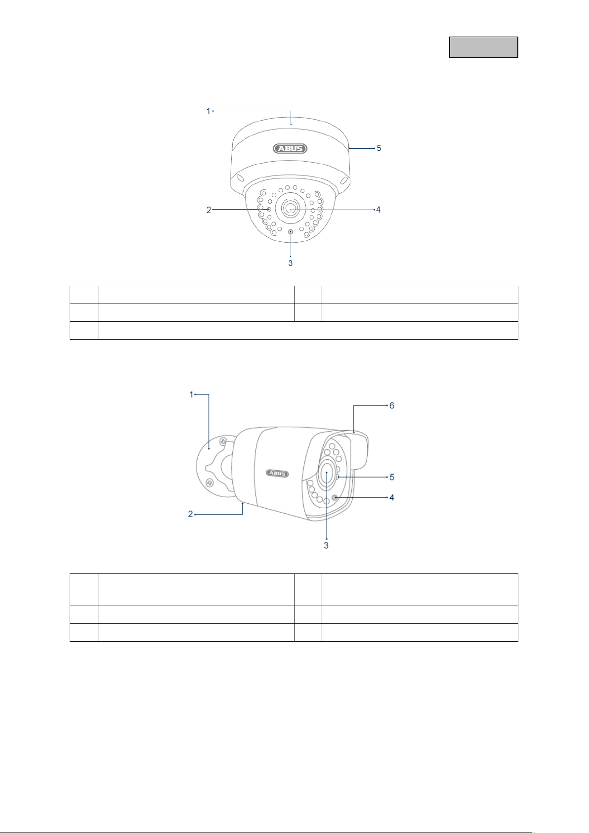
2.3. TVIP41560 / TVIP42560
1 Base plate 2 IR LEDs
3 Photo sensor 4 Lens
Internal microSD card slot & WPS/Reset button (TVIP41560 only)
5
2.4. TVIP61560 / TVIP62560
1 Camera holder 2 Covered microSD card slot
& WPS/Reset button (TVIP61560 only)
3 Lens 4 Photo sensor
5 IR LEDs 6 Sun shield
11

English
Connections (TVIP41560 / TVIP42560 / TVIP61560 / TVIP62560)
1
12 V DC power supply connection (round plug 5.5x2.1 mm)
2 Network access (RJ45, PoE-compatible)
The network acces s includes a cover, which can be used if necessary. T his cover provides
additional protection by preventing moisture from entering the equipment. When using the
cover, the network c able must only be connected (cr imped) to the network plug once it has
been passed through the cover. In addition, the connections (as well as the power supply
connection) can be sealed with insulation tape.
12

English
3. Description of hardware functions
3.1. Status LEDs
TVIP11561
LED Status Description
Alarm LED
LED status
Link LED
TVIP21560
LED Status Description
Status bar
TVIP41560 / TVIP42560 / TVIP61560 / TVIP62560
There are no visible status LEDs for these cameras.
Lights red A camera schedule is active
Lights blue No camera schedule is active
Lights blue Camera has a malfunction
Off Camera does not have a malfunction
Flashes orange Network connected
Off Network not connected
Lights blue
Flashes blue
Lights red A camera schedule is active
Flashes red Camera has a malfunction
Network connected,
No camera schedule is active
Network not connected,
No camera schedule is active
13
English
3.2. Reset
To reset the camer a to its factor y settings, first disconnect the power supply. Keep the res et button
pressed and reconnect the power supply to the camera. Continue pressing the reset button for another
15 seconds, then release.
Note
On some cameras , the sa m e button is used f or the r es et func tion a nd the WPS function.
Please refer to the description of the camera.
3.3. WPS
To use the WPS function via the hardware button, connect the camera to the power supply. Wait
approximately one minute until the camera has fully started up. Then, first enable the WPS function on
your receiver (router or r ecorder). Next, press an d hold down the W PS button on the camera for 15
seconds.
Note
On some cameras , the sa m e button is used f or the r es et func tion a nd the WPS function.
Please refer to the description of the camera.
3.4. Alarm input/output
The alarm inputs/outputs are identified as follows on the cameras:
• I = Input
• O = Output
• G = Earth (ground)
The connections are potential-free relays which can be operated with the following maximum
connection voltages:
• Max. 120 VAC / 1A
• Max. 24 VDC / 1A
Connect your peripherals as follows:
• Sensor:
Connect your sensor to the output and earth.
• Actuator:
Connect your actuator to the output and earth.
Note for TVIP11561
The earth can be used simultaneously for a sensor (input + earth) and an actuator (output
+ earth).
14
English
4. Mounting/installation
IMPORTANT!
The camera must be disconnected from the power supply during installation.
Note
You will find installation illustrations in the quick start guide for the camera in question.
4.1. TVIP11561
Mounting the camera
Use the accompanying drilling template or mount for drilling the mounting holes.
The drilling distance is 44 mm.
Orientation of the camera
The direction of the camera can be adjusted using the ball joint; loosen the fixing screws and adjust the
camera.
Important:
Do not forget to tighten up the screws again!
4.2. TVIP21560
Mounting the camera
Use the accompanying drilling template or mount for drilling the mounting holes.
Drill the holes in advance and insert the accompanying screw anchor.
Use the accompanying screws to fasten the ceiling bracket in place.
Important:
Please note that t h e arr o w and t he lab el "F RON T " on t he c e il in g br ac ket points in the r igh t
direction.
Orientation of the camera
Then place the camera onto the ceiling bracket and latch the camera in place by rotating it anticlockwise.
15
English
1
2
3
4.3. TVIP41560 / TVIP42560
Mounting the camera
Loosen the fixing screws for the camera dome and remove them. Use
the accompanying drilling template for drilling the mounting holes.
Secure the base plate with the screws and dowels provided.
Use the fixing scre ws to sc rew the cam era dom e back on to th e camera. Adjus t the or ientation of the
camera before doing this.
Orientation of the camera
First, undo the black dome cover. Loosen the screws at the side of the bracket to align the lens.
The camera can be aligned in three axes.
Panning: 0°–355°
Inclination: 0°–65°
Rotation: 0°–360°
Important:
Do not forget to tighten up the screws again!
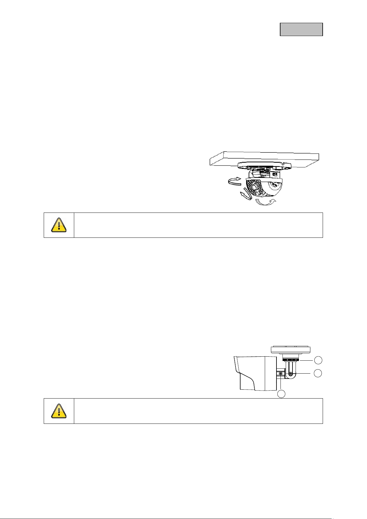
4.4. TVIP61560 / TVIP62560
Mounting the camera
Use the accompanying drilling template for drilling the mounting holes.
Secure the base plate with the screws and dowels provided.
Orientation of the camera
The camera can be aligned in three axes.
Panning: 0°–360°
Loosen the rotary wheel (1) to adjust the alignment horizontally.
Inclination: 0°–90°
Loosen the screw (2) to adjust the alignment vertically.
Rotation: 0°–360°
Loosen the screw (3) to adjust the rotation of the camera image.
Important:
Do not forget to tighten up the screws again!
16
English
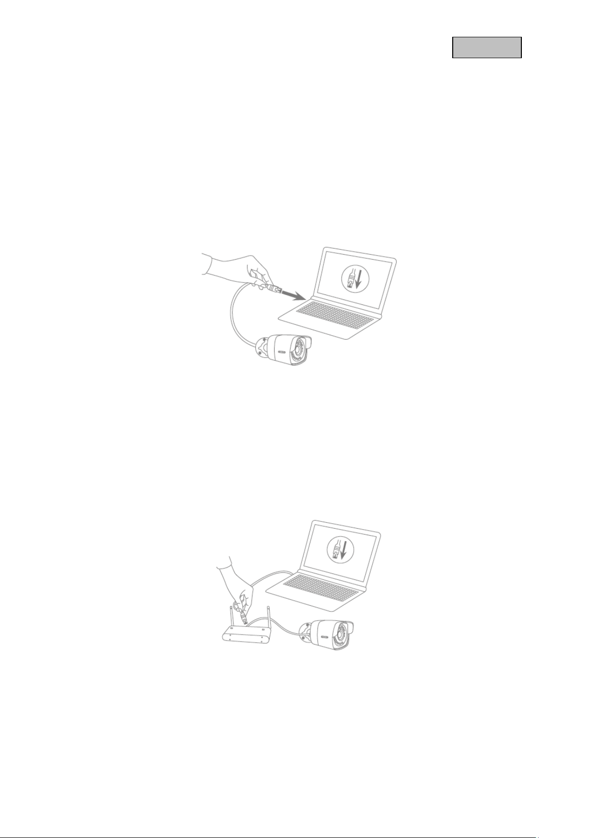
5. Initial start-up
The network cam era automatically detects whet her a direct connection bet ween the PC and camer a
should be establis hed. A crossover network cable is not required for this. You can use the s upplied
patch cable for direct connection for initial start-up.
Connecting the network camera directly to a PC/laptop
1. Ensure that a CAT 5 network cable is used.
2. Connect the cable to the Ethernet interface of the PC/laptop and the network camera.
3. Connect the network camera to the power supply.
4. Configure the network interface of your PC/laptop to the IP address 192.168.0.2
Connecting the network camera to a router/switch
1. Ensure that a CAT 5 network cable is used for the connection.
2. Connect the PC/laptop to the router/switch.
3. Connect the network camera to the router/switch.
4. Connect the network camera to the power supply.
5. If a DHCP server is available on your network , set the network interfac e of your PC/laptop to
"Obtain an IP address automatically".
6. If no DHCP server is ava ilable, co nfigure t he network interfac e of your P C/laptop to 192.168.0. 2
and the default gateway to 192.168.0.1.
17
English
6. First access
The first access to the IP camera simultaneously enables the device and makes it ready for operation.
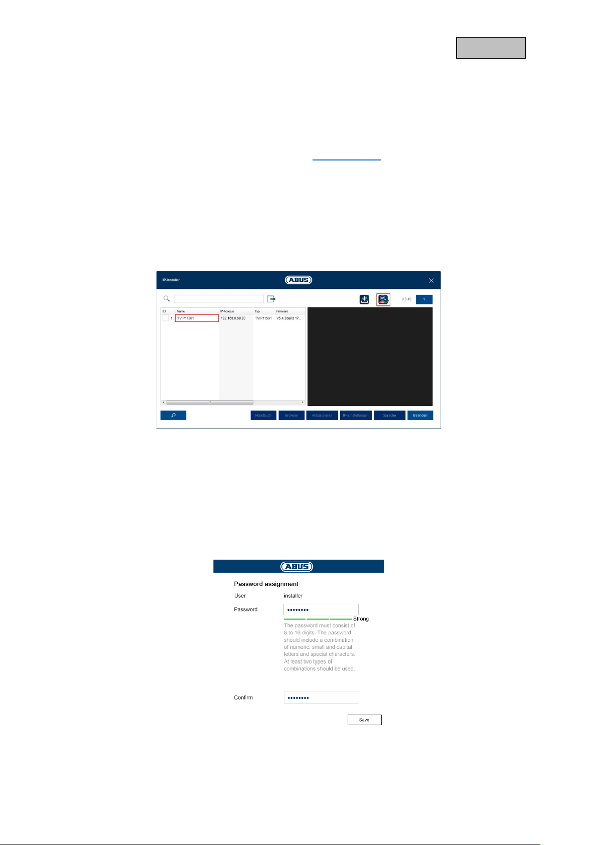
6.1. First access with ABUS IP Installer
You can initiate firs t access to the IP cam era using the IP Installer . The IP Ins taller is included on t he
enclosed CD or can be downloaded from our website www.abus.com
Install the IP Installer on your W indows PC. Make sure you have installed the latest version. The
highlighted icon on the screenshot below shows you whether a new version is ava ila ble.
When the IP Installer is started, yo ur network will automatically be scanned for ABUS IP cameras.
Double-click the camera you wish t o s e t up in order to open th e c amera’s web int er f ac e. Al terna t ive l y,
you can use the “Enable” button to carry out the activation via the IP Installer.
.
6.2. Password assignment - Activation
Once you have opened the camera’s web interface for the first time or when you use the IP Installer for
activation, a dialogue box will appear prompting you to enter a password.
No administrator password is set prior to delivery. The administrator user name “installer” has been set
at the factory and can be changed in the settings later.
First enter a password that meets the specified requirements and confirm it. Then click on “Save”.
18
 Loading...