

160
Approximate dimensions
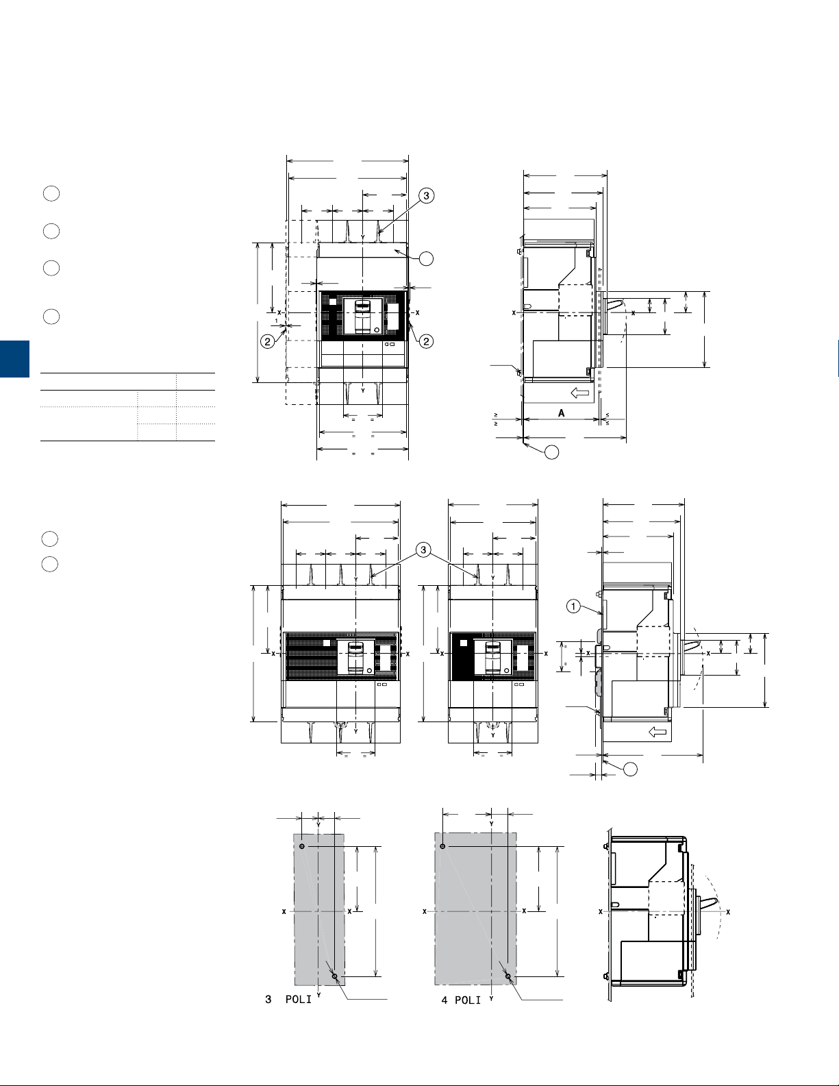
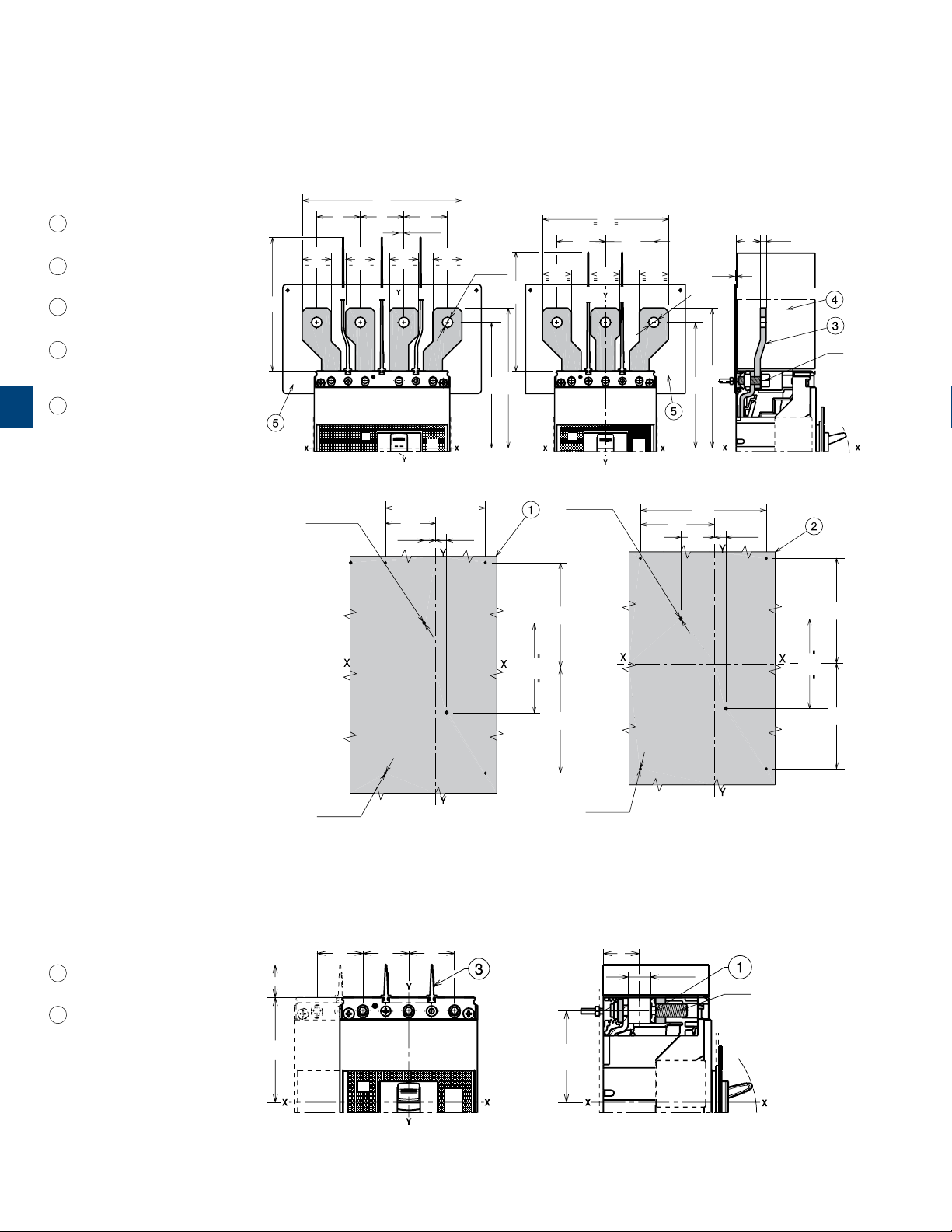
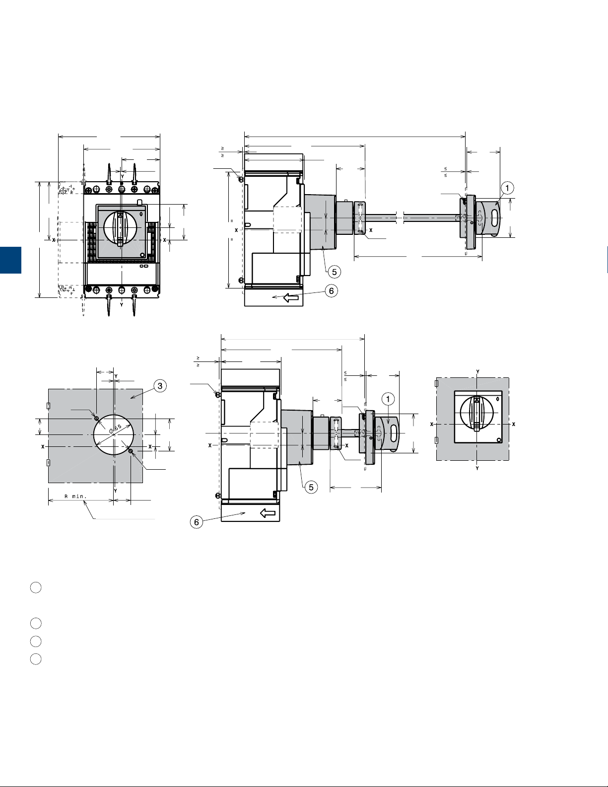
Tmax XT4 - Installation for fixed circuit breaker
Mounting on the backplate
140 (4P)
1.38
35
0.04
1
5.51
135
5.31
35
1.38351.38
45
1.77
100
3.94
105 (3P)
4.13
52.5
2.07
0.04
4
1
1.1Nm
Captions
1 Insulating plate
compulsory
2 Overall dimension of optional
wiring ducts
3 25mm insulating barriers
between phases (compulsory)
provided
4 Front carter compulsory
for through door of the
panel ≤ 25mm/0,98"
5
With standard flange III - IV 86
Without flange
III - IV 83.5
III - IV 91.5
80
3.15
6.30
A
3
0.12
1
0.04
95.5
3.76
90.5
3.56
82.5
3.25
24
0.63
0.94
41
1.61
87
3.42
1SDC21033IF0001
117
4.61
2
0.08
16
1
Captions
1 Mounting bracket
3 25mm insulating barriers
between phases (compulsory)
provided
Mounting on DIN 50022 rail
140 (4P)
5.51
135
5.31
52.5
1.77
2.07
35
1.38
160
6.30
45
160
6.30
35
1.38351.38
80
3.15
Drilling templates for the backplate
17.5
0.69
17.5
0.69
1.5
0.06
95.5
3.76
90.5
3.56
82.5
3.25
24
0.94
16
0.63
41
1.61
87
3.42
117
4.61
1SDC21034IF0001
1
105 (3P)
4.13
100
3.94
52.5
2.07
35
1.38351.38
80
3.15
35
1.38
3.5
0.14
1.1Nm
52.5
2.07
1.77
45
17.5
0.69
7.5
0.29
1
0.04
5/78 SACE Tmax XT UL/CSA | US Technical Catalog
3 POLES
69.5
2.74
Ø 4.5 - M4
Ø 0.18
139
5.47
4 POLES
69.5
2.74
Ø 4.5 - M4
Ø 0.18
139
5.47
1SDC21035IF0001
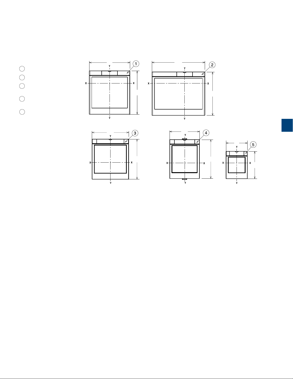
Flanges
Captions
1
Flange for fixed circuit breaker III
2
Flange for fixed circuit breaker IV
3 Flange for fixed circuit breaker
III-IV with MOE and FLD
4 Flange for circuit breaker III-IV
with direct rotary handle RHD
5 Optional flange
116
4.56
104.5
4.11
123.8
114.3
4.87
4.5
151
5.94
3.35
4.87
123.8
85
61
2.40
111
4.37
78
3.07
1SDC21036IF0001
5
US Technical Catalog | SACE Tmax XT UL/CSA 5/79
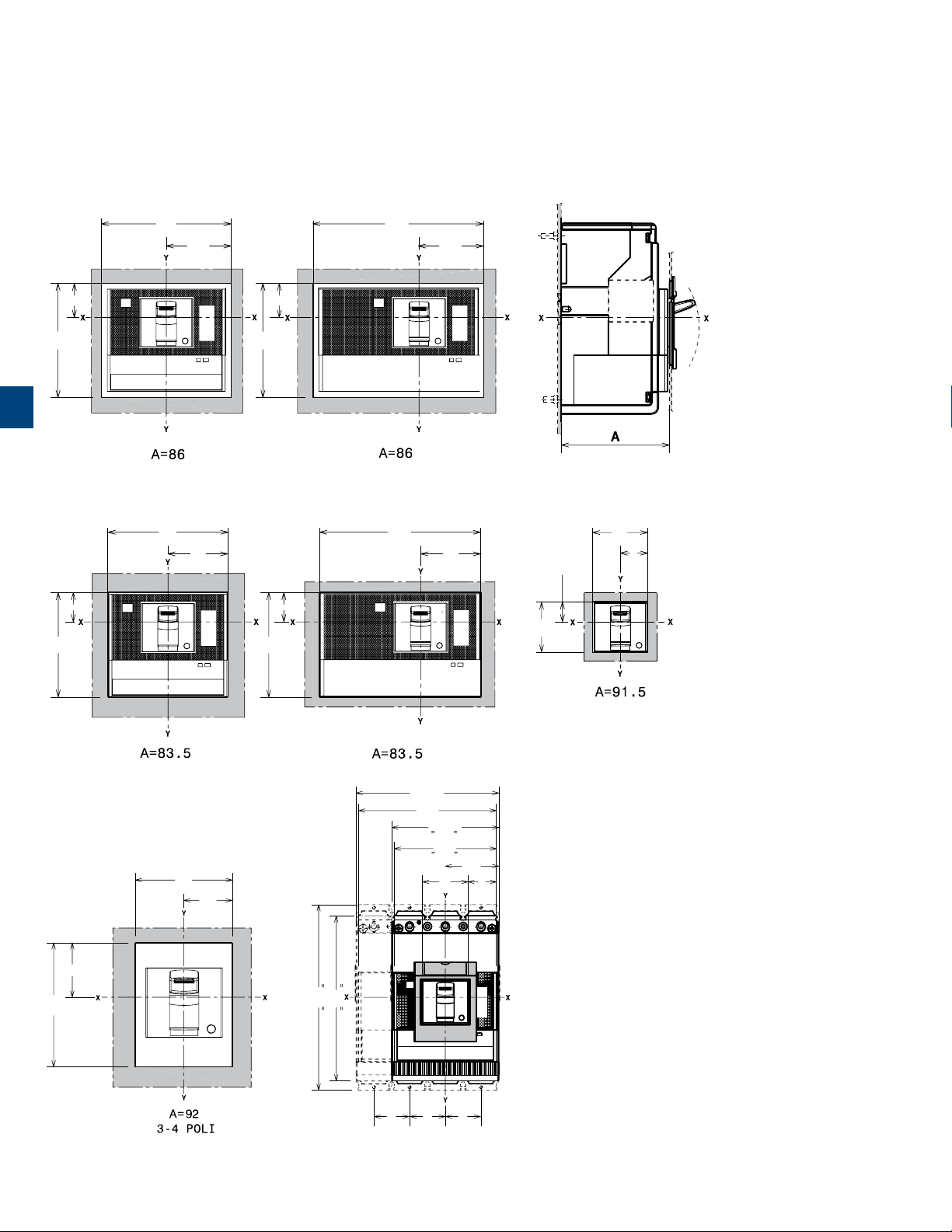
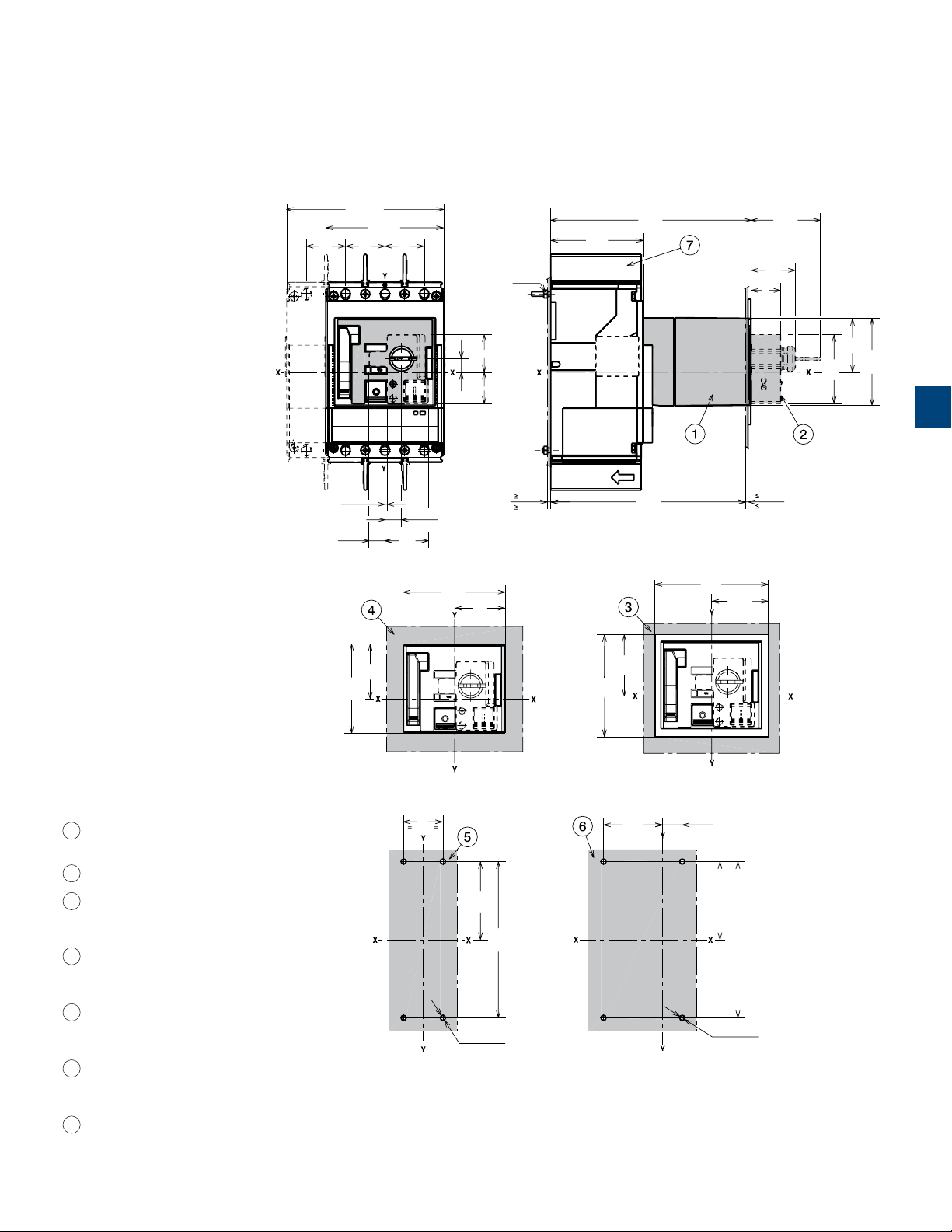
Approximate dimensions
Tmax XT4 - Installation for fixed circuit breaker
Drilling templates for compartment door
With standard flange
29
97
3.82
5
Without flange
25
89
3.50
1.14
0.98
110
4.33
3 POLES
102
4.01
55
2.17
51
145
5.71
29
1.14
97
3.82
55
2.17
1SDC21037IF0001
4 POLES
0.67
47
1.85
23.5
0.93
1SDC21038IF0001
137
5.39
2
25
0.98
89
3.50
51
2
17
43
1.69
3 POLES
With optional flange
57
2.24
28.5
1.12
32
1.26
73
2.87
3-4 POLES
5/80 SACE Tmax XT UL/CSA | US Technical Catalog
3-4 POLES
4 POLES
140 (4P)
5.51
135
5.31
105 (3P)
4.13
100
3.94
52.5
2.07
30
1.18
182
162
7.16
6.38
35
1.38351.38351.38
1SDC21039IF0001
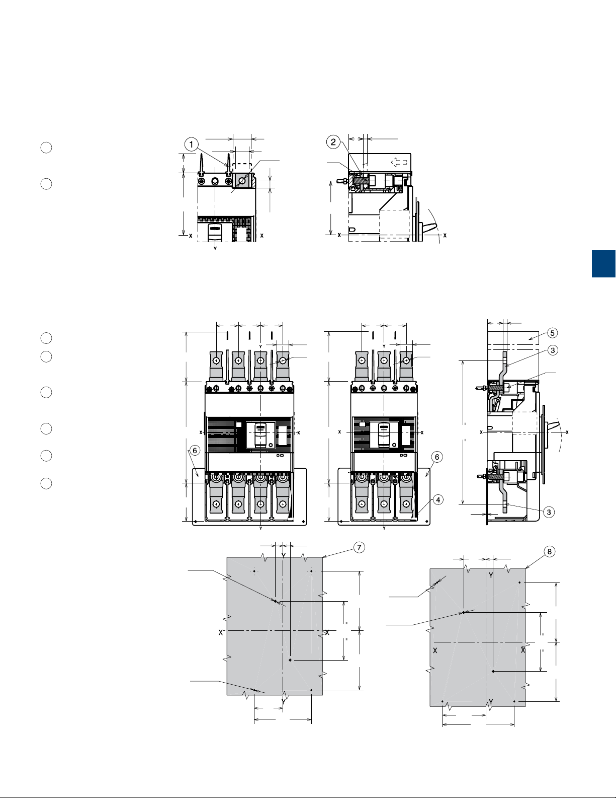
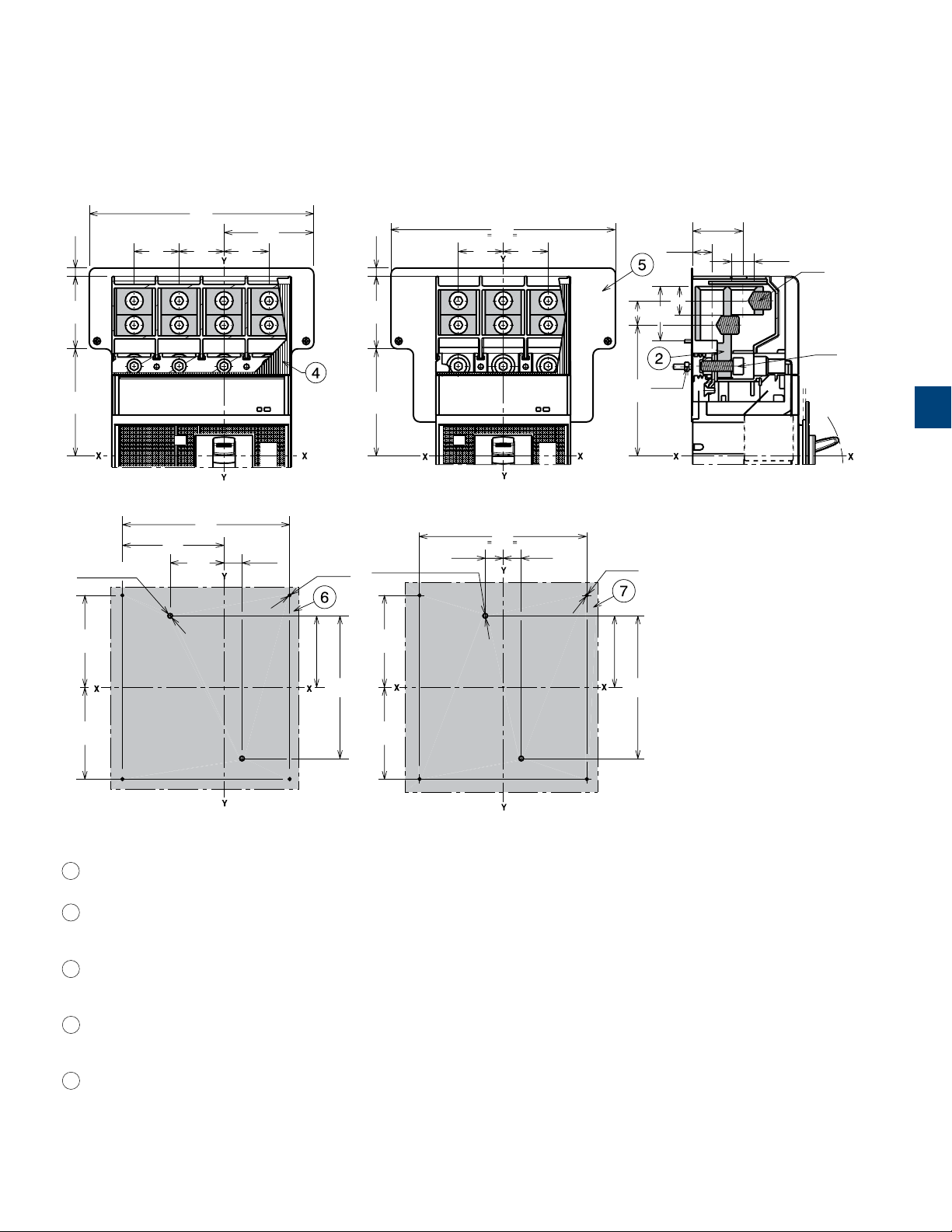
Approximate dimensions
Tmax XT4 - Terminals for fixed circuit breaker
Terminals F
Captions
1 25mm insulating barriers
between phases (compulsory)
provided
2 Top terminal covers with degree
of protection IP30 (optional) not
provided
Captions
3 Front extended terminals
4 Terminal covers with degree of
protection IP40 (optional) not
provided
5 100mm insulating barriers
between phases (compulsory)
provided
24 MAX
0.94
17.5
25
80
0.69
0.98
3.15
Terminals EF
35
1.38351.38351.38
~ 100
~ 3.94
Ø 8.2
Ø 0.32
9 MAX
0.35
19.5
0.77
Ø 10
Ø 0.39
8Nm
70
~ 100
2.76
~ 3.94
19
0.74
24 MAX
0.94
35
1.38351.38
19.5
0.77
Ø 10
Ø 0.39
1SDC21040IF0001
25
0.9860.24
5
8Nm
6 Insulated plate provided
compulsory for Ue>440V
7 Drilling template for 3p circuit
breaker
8 Drilling template for 4p circuit
breaker
160
6.30
60
2.36
3 POLES
Ø 4.5 - M4
Ø 0.18
Ø 2.65
Ø 0.10
17.5
0.69
67.5
2.66
5.31
135
17.5
0.69
160
60
6.30
2.36
139
5.47
140.5
140.5
5.53
5.53
4 POLES
Ø 2.65
Ø 0.10
Ø 4.5 - M4
Ø 0.18
226
102.5
4.04
8.90
52.5
2.07
0.04
170
1
17.5
0.69
5.53
140.5
139
5.47
5.53
140.5
1SDC21041IF0001
US Technical Catalog | SACE Tmax XT UL/CSA 5/81
Approximate dimensions
Tmax XT4 - Terminals for fixed circuit breaker
Terminals ES
Captions
1 Drilling template for 3p circuit
breaker
2 Drilling template for 4p circuit
breaker
3 Front extended spread
terminals
4 200mm insulating barriers
between phases (compulsory)
provided
5 Insulated plate provided com-
5
pulsory for Ue>440V
~ 200
~ 7.87
165
6.50
45
1.77451.77451.77
30
1.18
30
1.18301.18301.18
Ø 4.5 - M4
Ø 0.18
77.5
3.05
17.5
0.69
0.20
5
155
6.10
17.5
0.69
Ø 10.5
Ø 0.41
145
130
5.12
3 POLES
~ 200
5.71
~ 7.87
1.18
30
Ø 4.5 - M4
163
6.42
50
1.97
Ø 0.18
130
5.12
1.18
5.12
145
0.04
1
5.71
25
0.9860.24
8Nm
50
1.97
30
1.18
30
Ø 10.5
Ø 0.41
130
4 POLES
195
7.68
115
4.53
52.5
2.07
17.5
0.69
163
6.42
Captions
1 1x2,5...50mm2 terminals
FCCuAl
3 25mm insulating barriers
between phases (compulsory)
provided
Ø 2.65
Ø 0.10
1x2,5...50mm2 terminals FCCuAl
35
1.38351.38351.38
~ 25
~ 0.98
80
3.15
139
5.47
163
139
5.47
163
6.42
Ø 2.65
Ø 0.10
27.5
1.08
70
2.76
17x17
0.67x0.67
10Nm
1SDC21044IF0001
6.42
1SDC21043IF0001
5/82 SACE Tmax XT UL/CSA | US Technical Catalog
2x35...150mm2 terminals FCCuAl
175
6.5
0.26
56.5
2.22
83.5
3.29
Ø 4.5 - M4
Ø 0.18
6.89
35
1.38351.38
163
6.42
99
3.90
52.5
2.07
35
1.38
17.5
0.69
70
2.76
Ø 2.5
Ø 0.09
6.5
0.26
56.5
2.22
83.5
3.29
Ø 4.5 - M4
Ø 0.18
35
1.38351.38
17.5
0.69
175
6.89
163
6.42
17.5
0.69
Ø 2.5
Ø 0.09
19
102
0.74
4.01
42
1.1Nm
15
0.59
1.65
39
1.53
Ø 18
16Nm
Ø 0.71
22
0.87
8Nm
5
89.5
3.52
89.5
3.52
Captions
2 2x35...150mm2 terminals
FCCuAl
4 Terminal covers with degree
of protection IP40 (optional)
provided
5 Provided rear insulated
plate (compulsory for CuAl
2x150mm2 cables)
6 Drilling template for mounting
circuit breaker IV with insulating
plate
7 Drilling template for mounting
circuit breaker III with insulating
plate
69.5
2.74
139
5.47
89.5
89.5
3.52
3.52
69.5
2.74
139
5.47
1SDC21045IF0001
US Technical Catalog | SACE Tmax XT UL/CSA 5/83
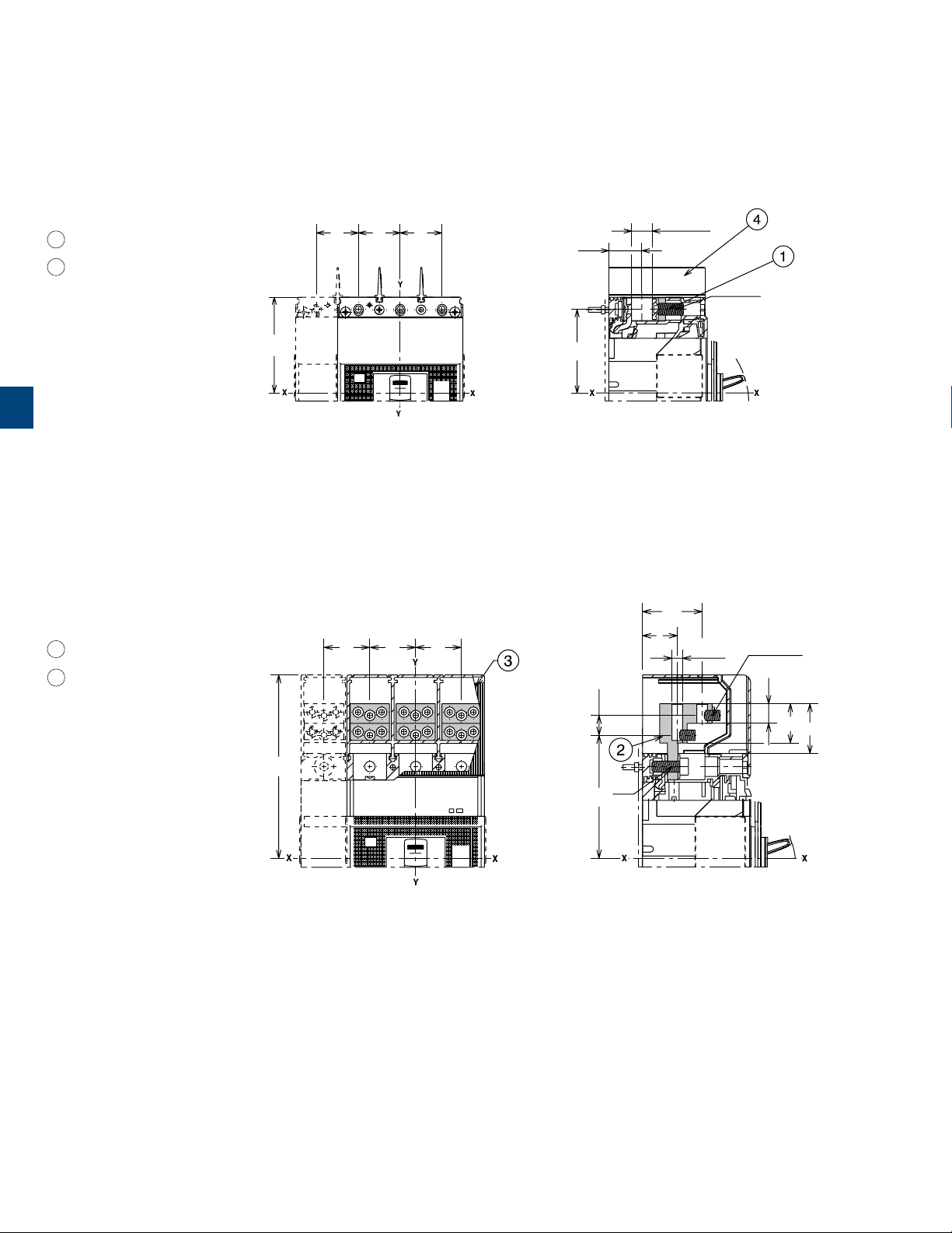
Approximate dimensions
Tmax XT4 - Terminals for fixed circuit breaker
Terminals FCCu
Captions
1 Terminals FCCu
4 25mm insulating barriers
between phases (compulsory)
provided as standard with the
circuit breaker
5
Captions
2 Multi-cable terminals
3 Terminal covers with degree
of protection IP40 (optional)
provided
35
1.38351.38351.38
80
3.15
Terminals MC
35
1.38351.38351.38
18 x 18
27.5
1.08
70
2.76
15
0.59
0.71 x 0.71
45.5
1.79
26.5
1.04
14Nm
123.91 in. lbs
Ø 8.2
Ø 0.32
7Nm
61.95 in. lbs
15
0.59
30
1SDC21046IF0001
1.18
38
1.50
140
5.51
5/84 SACE Tmax XT UL/CSA | US Technical Catalog
8Nm
94
3.70
1SDC21047IF0001
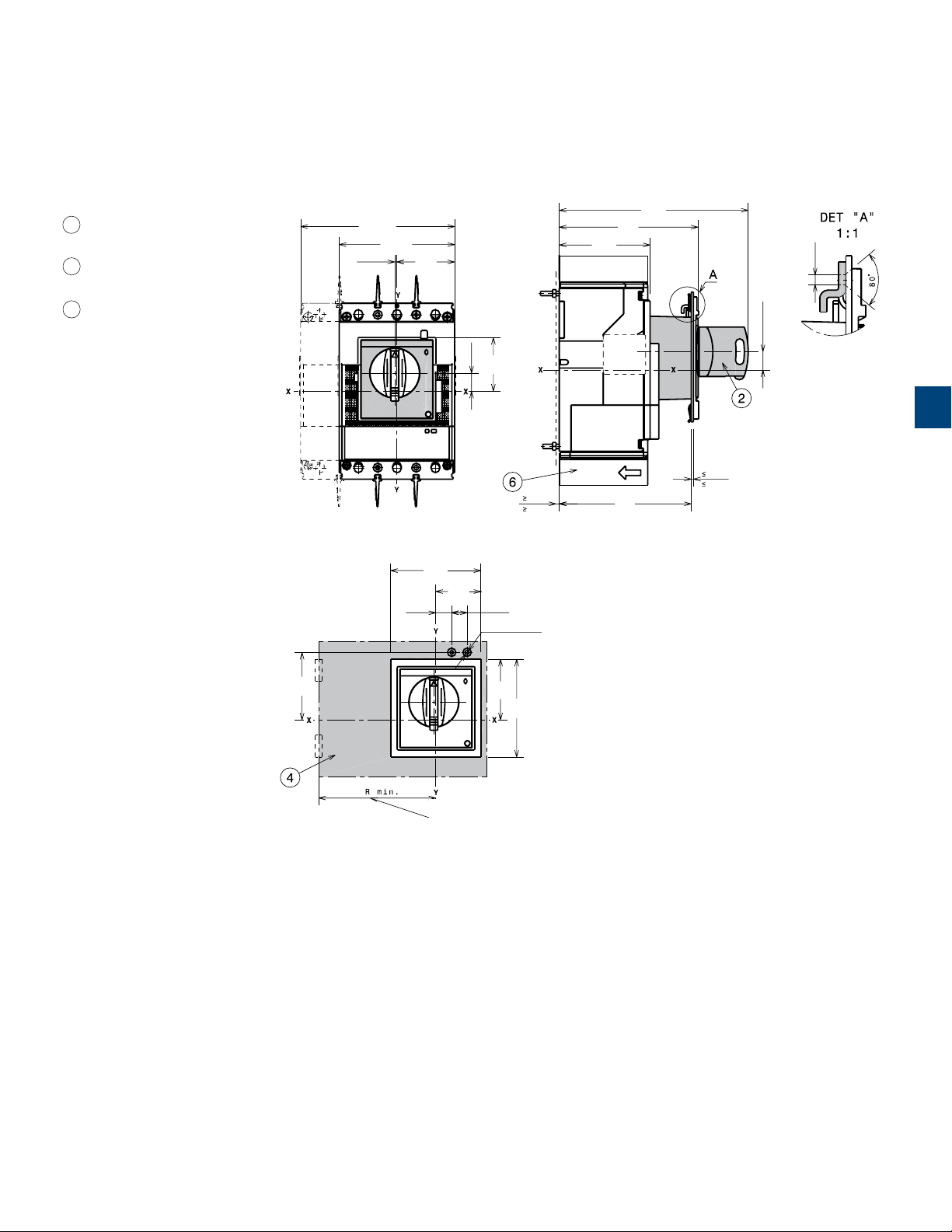
Approximate dimensions
Tmax XT4 - Accessories for fixed circuit breaker
Rotary handle operating mechanism on circuit breaker (RHD)
Captions
2 Rotary handle operating
mechanism on circuit breaker
4 Drilling template of door with
direct rotary handle
6 25mm insulating barriers
between phases
140 (4P)
5.51
2
0.08
105 (3P)
4.13
14.5
0.57
52.5
2.07
82
3.23
41
1.61
16.5
0.65
14
0.55
0.08 x Ø 0.14
48.8
1.92
2 x Ø 3.5
3
0.12
82.5
3.25
4.96
120
4.72
126
172
6.77
2
0.08
(16.5)
(0.65)
Ø 3.5
Ø 0.14
5
61.5
2.42
200
7.87
MINIMUM ROTATION RADIUS
FOR DOOR FULCRUM
55.3
2.18
89
3.50
1SDC21048IF0001
US Technical Catalog | SACE Tmax XT UL/CSA 5/85
Approximate dimensions
Tmax XT4 - Accessories for fixed circuit breaker
Rotary handle operating mechanism of the compartment door (RHE)
140 (4P)
5.51
105 (3P)
4.13
52.5
160
6.30
2.07
2
0.08
80
3.15
16.5
0.65
48.8
1.1Nm
1.92
5
3
0.12
1.1Nm
1.77
22.5
0.89
Ø 5
Ø 0.20
200
7.87
23.5
0.93
2
0.08
23.5
MINIMUM ROTATION RADIUS
FOR DOOR FULCRUM
0.93
16.5
Ø 5
Ø 0.20
0.65
45
HEIGHTS FOR DOOR WITH MAXIMUM DISTANCE
174.2
6.36
174.2
6.36
3
0.12
160
6.30
HEIGHTS FOR DOOR WITH MINIMUM DISTANCE 171
82.5
3.25
187.95
7.40
16.5
0.65
82.5
3.25
16.5
47.95
1.89
0.63
597.95
23.54
47.95
1.89
2
0.08
1.4Nm
1.4Nm
46
1.81
2
0.08
1.4Nm
Ø 54
Ø 2.13
1.4Nm
461
18.15
46
1.81
Ø 54
Ø 2.13
1SDC21049IF0001
51
2
Captions
1
Rotary handle operating
mechanism of the compartment
door
3 Drilling template for RHE
5 Transmission unit
6 25mm insulating barriers
between phases
5/86 SACE Tmax XT UL/CSA | US Technical Catalog
Stored energy motor operator (MOE)
140 (4P)
5.51
105 (3P)
35
1.38351.38351.38
4.13
1.1Nm
82.5
3.25
178.3
7.02
26.5
1.04
39.5
1.56
61.5
2.42
14.3
0.56
1.7
0.07
79.5
3.13
61.5
2.42
48
1.89
77.3
3.04
12
0.47
33.5
1.32
28
1.10
5
50.5
1.99
2
0.08
3
14.8
0.58
38.8
1.53
91
3.58
1.77
49
1.93
0.12
45
172
6.77
101
3.97
54.7
2.15
91
3.58
Captions
1 Stored energy motor operator
(MOE)
2 Key lock (not provided)
3 Drilling template of door with
direct rotary handle with flange
(MOE)
4 Drilling template of door with
direct rotary handle without
flange (MOE)
5 Drilling template for mounting
circuit breaker III on the
backplate
6 Drilling template for mounting
circuit breaker IV on the
backplate
7 25mm insulating barriers
between phases
35
1.38
3 POLES
69.5
2.74
Ø 4.5 - M4
Ø 0.18
139
5.47
52.5
2.07
17.5
0.69
69.5
2.74
139
Ø 4.5 - M4
Ø 0.18
5.47
1SDC21050IF0001
4 POLES
US Technical Catalog | SACE Tmax XT UL/CSA 5/87

Approximate dimensions
Tmax XT4 - Accessories for fixed circuit breaker
Front for lever operating mechanism (FLD)
140 (4P)
5.51
35
35
1.38
1.38351.38
90 (3P)
3.54
36.5
1.44
5
160
6.30
52.5
2.07
7
0.27
78.4
3.09
29.6
1.16
82.5
3.25
126
4.96
33
1.30
0.26
2.55
0.10
6.5
12
0.47
Ø 3.5
Ø 0.14
Captions
1 Front for lever operating
mechanism (FLD)
2 Key lock (not provided)
3 Drilling template of door with
direct rotary handle with flange
(FLD)
4 Drilling template of door with
direct rotary handle without flange
(FLD)
61.5
2.42
27.5
1.08
1.38
52.5
2.07
61.5
120
4.72
2.42
17.5
0.69
69.5
2.74
200
7.87
139
5.47
2
0.08
14.5
0.57
101
3.97
50.5
1.99
14
0.55
Ø 3.5
Ø 0.14
55
2.17
91
3.58
3
0.12
91
3.58
45.5
1.79
69.5
2.74
139
5.47
14
0.55
Ø 3.5
Ø 0.14
48.7
1.92
79
3.11
14.5
0.57
200
7.87
35
5 Drilling template for mounting
circuit breaker III on the backplate
6 Drilling template for mounting
circuit breaker IV on the backplate
7 25mm insulating barriers between
phases
5/88 SACE Tmax XT UL/CSA | US Technical Catalog
3 POLES
Ø 4.5 - M4
Ø 0.18
4 POLES
Ø 4.5 - M4
Ø 0.18
1SDC21051IF0001

Captions
1 Ekip Display or LED Meter
2 Optional wiring ducts
3 25mm insulating barriers
between phases
Ekip Display or LED Meter
105 (3P)
4.13
100
3.94
~ 25
~ 0.98
45
1.77
78.6
3.10
160
6.30
0.04
1
0.04
99.35
3.91
95.5
3.76
90.5
3.56
82.5
3.25
1
38.5
1.52
19.3
0.76
1.1Nm
3
0.12
117
4.61
2
0.08
16
0.63
24
0.94
41
1.61
87
3.42
5
~ 25
160
~ 0.98
6.30
0.04
140 (4P)
5.51
135
5.31
1
45
1.77
78.6
3.10
52.5
2.07
0.04
1
38.5
1.52
19.3
0.76
1SDC21052IF0001
US Technical Catalog | SACE Tmax XT UL/CSA 5/89

5.35
Approximate dimensions
Tmax XT4 - Accessories for fixed circuit breaker
Residual current RC Sel
140
5.51
24 MAX
0.94 MAX
35
35
35
1.37
1.37
1.37
0.31
8
19
0.74
6 MAX
0.23 MAX
52.5
2.06
17.5
0.68
80
3.14
236
9.29
5
24 MAX
0.94 MAX
134
5.27
145
173
29
6.81
5.70
1.14
54.5
2.14
9 MAX
9 MAX
3
0.11
0.31
70
2.75
0.35 MAX
0.35 MAX
8
215
89
0.74
0.11
3.50
8.46
19
3
25
0.98
6 MAX
0.23 MAX
137
5.39
0.07
2
51
2.00
69.5
2.73
87
3.42
81
3.18
163
6.41
58
2.28
80
3.14
4.5
0.17
215
8.46
Captions
1 Residual current
2 Front terminals
7 Drilling template of door
with direct rotary handle and
mounting with flange
8 Drilling template of door
with direct rotary handle
and
mounting without flange
9 Drilling template for mounting
circuit breaker on sheet
5/90 SACE Tmax XT UL/CSA | US Technical Catalog
With standard flange IV 86
Without flange IV 83.5
60
2.36
50
1.96
136
1SDC21052DF0001
A

Approximate dimensions
Tmax XT4 - Installation for plug-in circuit breaker
Mounting on the backplate
Captions
1 Fixed part
2 Moving part
Mounting at 50mm A
With standard flange III - IV 136
Without flange
III - IV 133.5
III - IV 141.5
140 (4P)
5.51
105 (3P)
4.13
35
1.38351.38351.38
52.5
2.07
182
1.1Nm
7.16
3
0.12
164.4
6.47
140.5
132.5
5.22
145.5
5.73
5.53
2
0.08
5
1SDC21053IF0001
Mounting at 70mm for
A
front extended terminals
With standard flange III - IV 156
Without flange
III - IV 153.5
III - IV 161.5
US Technical Catalog | SACE Tmax XT UL/CSA 5/91

Approximate dimensions
Tmax XT4 - Installation for plug-in circuit breaker
Drilling templates
5
92
3.62
48
1.89
3 POLES
107
4.21
60
2.36
53.5
2.11
38
1.50
72
Ø 4.5 - M4
Ø 0.18
Ø 4.5 - M4
Ø 0.18
92
2.83
3.62
48
1.89
4 POLES
142
5.60
60
2.36
53.5
2.11
38
1.50
72
2.83
60
2.36
3-4 POLES
38
1.50
Ø 4.5 - M4
Ø 0.18
72
2.83
1SDC21054IF0001
5/92 SACE Tmax XT UL/CSA | US Technical Catalog

Flanges
Captions
1 Flange for plug-in circuit
breaker III
2 Flange for plug-in circuit
breaker IV
3 Flange for plug-in circuit breaker
III-IV with MOE and FLD
4 Flange for circuit breaker III-IV
with direct rotary handle
5 Optional flange
116
4.56
104.5
4.11
123.8
4.5
114.3
4.87
151
5.94
85
3.35
111
4.87
123.8
4.37
5
61
2.40
78
3.07
1SDC21055IF0001
US Technical Catalog | SACE Tmax XT UL/CSA 5/93

140 (4P)
Approximate dimensions
Tmax XT4 - Installation for plug-in circuit breaker
Drilling templates compartment door
With standard flange
97
3.82
5
Without flange
89
3.50
110
4.33
55
2.17
29
1.14
29
1.14
97
3.82
3 POLES
102
4.01
51
2
25
0.98
25
0.98
89
3.50
145
5.71
4 POLES
137
5.39
55
2.17
1SDC21056IF0001
47
1.85
51
2
17
0.67
43
1.69
23.5
0.93
1SDC21057IF0001
3 POLES 4 POLES
With optional flange
57
2.24
28.5
1.12
32
1.26
73
2.87
B=142 C=162
3 - 4 POLI
3-4 POLES
5/94 SACE Tmax XT UL/CSA | US Technical Catalog
182
7.16
162
6.38
5.51
135
5.31
105 (3P)
4.13
100
3.94
45
1.77
35
1.38351.38351.38
52.5
2.07
1.18
3-4 POLES
30
1SDC21058IF0001

Approximate dimensions
Tmax XT4 - Terminals for plug-in circuit breaker
Terminals EF
35
1.38351.38351.38
~ 100
~ 3.94
17.5
0.69
Ø 8
Ø 0.31
22.5
0.89
104
4.09
113.5
4.47
50
1.97
15
0.59
0.16
4
8Nm
MOUNTING AT 50mm
70
2.76
35
1.38
0.16
4
MOUNTING AT 70mm
165.5
160.5
6.32
152.5
6.0
6.52
8Nm
5
1SDC21059IF0001
Captions
4 Front extended terminals
5 100mm insulating barriers
between phases (compulsory)
provided
Note: insulated plate to be provided by
customer
US Technical Catalog | SACE Tmax XT UL/CSA 5/95

Approximate dimensions
Tmax XT4 - Terminals for plug-in circuit breaker
Terminals ES
130
30
1.18
50
1.97
5.12
30
1.18
1.97
50
80.5
1.18
30
3.16
25
0.9860.24
77.5
3.05
155
6.10
107
4.21
53.5
2.11
3 POLES
Ø 2.6
Ø 0.09
Ø 10.5
Ø 0.41
~ 200
~ 7.87
5
114
4.49
164
6.46
179
7.05
8Nm
Ø 4.5 - M4
Ø 0.18
92
3.62
48
1.89
60
2.36
38
1.50
72
2.83
395
15.55
MOUNTING AT 50mm
115
4.53
195
7.68
142
5.60
53.5
2.11
4 POLES
Ø 2.6
Ø 0.09
~ 200
~ 7.87
30
1.18
45
1.77
30
1.18
165
6.50
45
1.77
30
1.18
0.20
45
1.77
30
1.18
5
Ø 10.5
Ø 0.41
Ø 4.5 - M4
Ø 0.18
114
4.49
Captions
1 Front extended spread terminals
2 200mm insulating barriers between phases
(compulsory) provided
3 Insulated plate (compulsory)provided
4 Drilling template for 3p circuit breaker
5 Drilling template for 4p circuit breaker
6 Adapter (compulsory) not
provided
5/96 SACE Tmax XT UL/CSA | US Technical Catalog
164
6.46
179
7.05
92
3.62
48
1.89
60
2.36
38
1.50
72
2.83
395
15.55
1SDC21060IF0001

Captions
1 1x1...185mm2 front terminals
FCCuAl
2 25mm insulating barriers
between phases (compulsory)
provided
6 Adapter (compulsory) not provi-
ded
1x2.5...50mm2 terminals FCCuAl
35
35
35
1.37
25
0.98
1.37
1.37
104
4.09
27.5
1.08
18
0.70
17x17
0.66x0.66
Captions
3 Provided high terminal covers
with degree of protection IP40
(compulsory for multi-cables
terminals)
4 Multicable terminals
6 Adapter (compulsory) not pro-
vided
Terminals MC
35
1.37
35
1.37
1.37
1SDC21061DF0001
5
MOUNTING AT 50mm
45.5
1.79
26.5
35
15
0.59
76.5
3.01
174
6.85
128
5.03
8.2
0.32
1.04
15
0.59
30
1.18
38
1.49
1SDC21063DF0001
MOUNTING AT 50mm
US Technical Catalog | SACE Tmax XT UL/CSA 5/97

Approximate dimensions
Tmax XT4 - Terminals for plug-in circuit breaker
Terminals HR/VR
70
2.76
17.7
70
5
2.76
20
0.79
0.70
77.5
77.5
3.05
3.05
50
1.97
5
0.20
Captions
1 Rear vertical terminals
2 Rear horizontal terminals
3 90mm insulating barriers
between phases (compulsory)
not provided
Ø 8.2
Ø 0.32
6Nm
MOUNTING AT
50mm
82.9
3.26
72.9
2.86
42.9
1.68
32.9
1.29
35
1.38
35
1.38
5
35
1.38
0.20
~ 90
~ 3.54
Ø 8.2
Ø 0.32
35
35
35
MOUNTING AT
17.7
0.70
1.38
1.38
20
0.79
1.38
~ 90
~ 3.54
50mm
82.9
3.26
72.9
2.86
42.9
1.68
32.9
1.29
6Nm
1SDC21061IF0001
5/98 SACE Tmax XT UL/CSA | US Technical Catalog

Approximate dimensions
Tmax XT4 - Accessories for plug-in circuit breaker
Stored energy motor operator (MOE)
140 (4P)
~ 100
~ 3.94
5.51
105 (3P)
35
1.38351.38351.38
4.13
19
0.74
1.97
132.5
50
5.22
37.5
1.48
31.1
1.22
63
2.48
Captions
227
8.94
182
~ 100
7.16
~ 3.94
9.3
0.36
101
3.97
33.5
28
1.32
1.10
48.5
50.5
1.99
1.91
78.5
3.10
208
8.19
3
0.12
54.7
2.15
5
222
8.74
91
3.58
45.5
1.79
91
3.58
2
0.08
49
1.93
79.5
3.13
1 Fixed part
2 Moving part
3 Stored energy motor operator
(MOE)
4 Key lock (not provided)
5 100mm insulating barriers
between phases (compulsory)
provided
6 Drilling template of door with
direct rotary handle with flange
7 Drilling template of door with
direct rotary handle without
flange
8 Extended terminals
200
7.87
200
7.87
1SDC21062IF0001
US Technical Catalog | SACE Tmax XT UL/CSA 5/99

140 (4P)
5.51
105 (3P)
4.13
35
1.38351.38351.38
~ 100
~ 3.94
~ 100
~ 3.94
227
8.94
182
7.16
9.6
0.38
81.6
3.21
208
8.19
50
1.97
15
0.59
170
6.69
132.5
5.22
2
0.08
3
0.12
1.1Nm
Ø 3.5
Ø 0.14
Approximate dimensions
Tmax XT4 - Accessories for plug-in circuit breaker
Front for lever operating mechanism (FLD)
140 (4P)
5.51
105 (3P)
35
1.38351.38351.38
~ 100
~ 3.94
5
227
182
8.94
7.16
4.13
0.59
9.6
0.38
81.6
3.21
208
8.19
1.1Nm
1.97
15
132.5
5.22
50
Ø 3.5
Ø 0.14
61.5
Captions
1 Fixed part
2 Moving part
~ 100
~ 3.94
2.42
200
7.87
14.5
0.57
91
3.58
50.5
1.99
3
0.12
14
Ø 3.5
0.55
Ø 0.14
55
2.17
91
3.58
61.5
2.42
170
6.69
200
7.87
14.5
0.57
91
3.58
45.5
1.79
14
0.55
2
0.08
Ø 3.5
Ø 0.14
48.7
1.92
79
3.11
1SDC21063IF0001
3 Front for lever operating
mechanism (FLD)
4 100mm insulating barriers between
phases (compulsory) provided
5 Drilling template of door with direct
rotary handle with flange
6 Drilling template of door with direct
rotary handle without flange
5/100 SACE Tmax XT UL/CSA | US Technical Catalog

Captions
1 100mm insulating barriers
between phases (compulsory)
provided
2 Ekip Display or LED Meter
Ekip Display or LED Meter
140 (4P)
5.51
105 (3P)
4.13
~ 100
~ 3.94
182
7.16
~ 100
~ 3.94
52.5
2.07
38.5
19.3
1.52
0.76
1.1Nm
0.59
149.35
5.88
145.5
5.73
132.5
5.22
50
1.97
15
0.16
4
5
MOUNTING AT 50mm
78.6
3.10
1.1Nm
35
1.38
70
2.76
0.16
169.35
6.67
165.5
6.52
152.5
6.0
4
1SDC21064IF0001
MOUNTING AT 70mm
US Technical Catalog | SACE Tmax XT UL/CSA 5/101

Approximate dimensions
Tmax XT4 - Accessories for plug-in circuit breaker
Residual current RC Sel
Captions
1 Residual current
3 Fixed part
4 Moving part
5 100mm insulating barriers
between phases (compulsory)
provided
6 Extended terminals
7 Drilling template of door
5
with direct rotary handle and
mounting with flange
8 Drilling template of door with di-
rect rotary handle and mounting
without flange
9 Drilling template for mounting
circuit breaker on sheet
146
5.74
0.11
100
3
145
5.70
15
0.5940.15
3.93
54.5
2.14
0.07
52.5
2.06
81
240
3.18
9.44
163
6.41
58
2.28
2
17.5
0.68
69.5
2.73
35
1.37
100
3.93
91
3.58
249
9.80
137
5.39
25
0.98
51
2.00
1.37
1.37
8
0.31
20
0.78
29
1.14
35
35
89
3.50
60
2.36
B
With standard flange IV 136
Without flange IV 133.5
5/102 SACE Tmax XT UL/CSA | US Technical Catalog
80
3.14
173
6.81
4.5
0.17
215
8.46
1SDC21067DF0001

Approximate dimensions
Tmax XT4 - Installation for withdrawable circuit breaker
Drilling templates for the backplate
92
3 POLES
3.62
107
4.21
53.5
2.11
92
3.62
48
1.89
60
2.36
38
1.50
72
Ø 4.5 - M4
Ø 0.18
Ø 4.5 - M4
Ø 0.18
48
1.89
2.83
4 POLES
142
5.60
53.5
2.11
38
1.50
72
2.83
5
60
2.36
38
1.50
72
2.83
Flanges
Captions
1 Flange for withdrawable
circuit breaker III-IV
C D
RHD 111 124.5
FLD - MOE 114.3 134.5
3-4 POLES
2.36
Ø 4.5 - M4
Ø 0.18
60
1SDC21066IF0001
1SDC21065IF0001
US Technical Catalog | SACE Tmax XT UL/CSA 5/103

102
Approximate dimensions
Tmax XT4 - Installation for withdrawable circuit breaker
Drilling templates for compartment door
With standard flange
29
97
3.82
5
Without flange
89
3.50
110
4.33
55
2.17
1.14
29
1.14
97
3.82
3 POLES
4.01
51
2
25
0.98
25
0.98
89
3.50
145
5.71
4 POLES
137
5.39
55
2.17
1SDC21067IF0001
47
0.67
1.85
23.5
0.93
51
2
17
43
1.69
3 POLES
With optional flange
57
2.24
28.5
1.12
32
1.26
73
2.87
B=142 C=162
3 - 4 POLI
3-4 POLES
5/104 SACE Tmax XT UL/CSA | US Technical Catalog
4 POLES
182
162
7.16
6.38
140 (4P)
5.51
135
5.31
105 (3P)
4.13
100
3.94
45
1.77
35
1.38351.38351.38
52.5
2.07
1.18
30
3-4 POLES
1SDC21069IF0001
1SDC21068IF0001

Approximate dimensions
Tmax XT4 - Terminals for withdrawable circuit breaker
Terminals EF
196.25
7.73
152.5
6.0
0.16
70
2.76
35
4
1.38
7Nm
1.1Nm
0.16
50
1.97
4
15
0.59
7Nm
1.1Nm
~ 100
~ 3.94
35
1.38351.38351.38
17.5
0.69
Ø 8
Ø 0.31
19.6
0.78
104
4.09
113.5
4.47
5
1SDC21075IF0001
MOUNTING AT 70mm
Captions
4 Front extended terminals
5 100mm insulating barriers
between phases (compulsory)
provided
Note: insulated plate (compulsory)
provided
MOUNTING AT 50mm
US Technical Catalog | SACE Tmax XT UL/CSA 5/105

Approximate dimensions
Tmax XT4 - Terminals for withdrawable circuit breaker
Terminals ES
205
8.07
165
6.50
45
1.77
30
1.18
0.24
80.5
3.16
6
0.98
165
6.50
130
5.12
25
1
0.04
30
1.18
50
1.97
30
1.18
1.97
50
30
1.18
Ø 10.5
Ø 0.41
30
1.18
1.77
45
30
1.18
45
1.77
1.18
30
Ø 10.5
Ø 0.41
0.20
5
~ 200
~ 7.87
6Nm
179
114
4.49
7.05
164
6.46
5
179
7.05
164
~ 200
6.46
114
~ 7.87
4.49
112.5
4.43
MOUNTING AT 50 mm
115
4.53
195
7.68
142
5.60
53.5
2.11
4 POLES
Ø 2.6
Ø 0.09
38
1.50
72
2.83
395
15.55
Ø 4.5 - M4
Ø 0.18
92
3.62
155
6.10
77.5
3.05
107
4.21
53.5
2.11
48
1.89
3 POLES
Ø 2.6
Ø 0.09
38
1.50
72
2.83
395
15.55
Ø 4.5 - M4
Ø 0.18
92
3.62
48
1.89
Captions
1 Front extended spread termi-
nals
2 200mm insulating barriers
between phases (compulsory)
provided
3 Insulated plate provided
compulsory for Ue>440V
4 Drilling template for 3p
circuit breaker
5 Drilling template for 4p
circuit breaker
6 Adapter (compulsory)
not provided
5/106 SACE Tmax XT UL/CSA | US Technical Catalog
60
2.36
60
2.36
1SDC21070IF0001

Captions
2 25mm insulating barriers
between phases (compulsory)
provided
4 Front terminals FCCuAl
5 Adapter (compulsory) not provi-
ded
1x2.5...50mm2 terminals FCCuAl
17x17
27.5
1.08
0.66x0.66
104
4.09
25
114
0.98
4.48
35
1.37
1.37
35
35
1.37
Captions
1 25mm insulating barriers
between phases (compulsory)
provided as standard with the
circuit breaker
2 Terminals FCCu
3 Adapter (compulsory) not provi-
ded
Captions
1 Multicable terminals
3 High terminal covers with
degree of protection IP40 (optional) provided
4 Adapter (compulsory) not pro-
vided
MOUNTING AT 50 mm
Terminals FCCu
MOUNTING AT 50 mm
Terminals MC
45.5
1.79
15
0.59
17x17
0.66x0.66
27.5
1.08
26.5
1.04
8.2
0.32
1SDC21076DF0001
35
35
35
1.37
25
0.98
114
104
4.09
15
0.59
28
1.10
38
1.49
4.48
35
1.37
35
1.37
1.37
35
1.37
1.37
76.5
1SDC21009GF00011SDC21079DF0001
3.01
5
128
5.03
MOUNTING AT 50 mm
91
6.85
US Technical Catalog | SACE Tmax XT UL/CSA 5/107

Approximate dimensions
Tmax XT4 - Terminals for withdrawable circuit breaker
Terminals HR/VR
5
0.20
77.5
3.05
70
2.76
77.5
3.05
Ø 8.2
Ø 0.32
70
2.76
5
20
0.79
MOUNTING AT 50 mm
MOUNTING AT 50 mm
82.9
3.26
72.9
32.9
1.29
42.9
1.68
2.86
17.7
0.70
20
0.79
82.9
3.26
72.9
2.86
42.9
1.68
32.9
1.29
17.7
0.70
35
1.38
35
7.5
1.38
35
1.38
35
1.38
0.29
35
1.38
Captions
1 Rear vertical terminals
2 Rear horizontal terminals
3 90mm insulating barriers
between phases (compulsory)
not provided
5/108 SACE Tmax XT UL/CSA | US Technical Catalog
Ø 8.2
Ø 0.32
~ 90
~ 3.54
Ø 8.2
Ø 0.32
~ 90
~ 3.54
1SDC21071IF0001

Approximate dimensions
Tmax XT4 - Accessories for withdrawable circuit breaker
Front for lever operating mechanism (FLD)
Ø 3.5
Ø 0.14
77.2
3.04
~ 100
182
~ 3.94
7.16
140 (4P)
5.51
105 (3P)
4.13
52.5
2.07
84.5
3.33
176.25
6.94
132.5
5.22
50
1.97
208
227
8.19
8.94
9.5
0.37
1.1Nm
164
5
6.46
~ 100
~ 3.94
35
1.38351.38351.38
Captions
1 Fixed part
2 Moving part
3 Front for lever operating
mechanism FLD
4 Drilling template of door with
direct rotary handle and fixed
flange
27.5
1.08
91
Ø 8
Ø 0.31
55
3.58
2.17
14.5
0.57
101
3.97
50.5
1.99
3
0.12
80
3.15
0.55
14
2 x Ø 3.5
0.08 x Ø 0.14
200
7.87
170
6.69
2
0.08
61.5
2.42
18
0.71
19
0.74
1SDC21072IF0001
5 100mm insulating barriers
between phases (compulsory)
provided
6 Extended terminals
US Technical Catalog | SACE Tmax XT UL/CSA 5/109

Approximate dimensions
Tmax XT4 - Accessories for withdrawable circuit breaker
Stored energy motor operator (MOE)
228.3
132.5
140 (4P)
5.51
105 (3P)
4.13
84.5
3.33
52.5
~ 100
~ 3.94
5
182
7.16
~ 100
~ 3.94
2.07
12
0.47
33.5
1.32
208
227
8.19
28
8.94
1.10
1.97
5.22
50
8.99
32.9
1.29
26.5
1.04
58.4
2.30
61.5
2.42
47.9
1.88
77.3
3.04
164
6.46
14.2
0.56
14.8
0.58
1.8
0.07
38.8
1.53
Captions
1 Fixed part
2 Moving part
3 Stored energy motor operator
(MOE)
4 Drilling template of door with
MOE and fixing flange
5 100mm insulating barriers
between phases (compulsory)
provided
2
0.08
18
0.71
19
0.74
1SDC21073IF0001
200
7.87
222
8.74
3
0.12
101
3.97
50.5
1.99
80
3.15
54.7
2.15
91
3.58
6 Extended terminals
7 Key lock (not provided)
5/110 SACE Tmax XT UL/CSA | US Technical Catalog
 Loading...