

Page 1

ACS 600, ACS 800
User’s Manual
This manual includes
•Safety
• Commissioning of the
Supply Section with ISU
• Functional Description
• Parameters
• Fault Tracing
• Technical Data
ACA 635 IGBT Supply Sections
260 to 4728 kVA
ACS 800-17 Line-side Converter
120 to 1385 kVA
Page 2

ACS 600 MultiDrive Manuals (Air-cooled Units, English Originals)
GENERAL MANUALS
*Safety and Product Information EN 63982229
• Complete general Safety Instructions
• Technical data for DSU and TSU supplies and Drive Sections: ratings,
power losses, dimensions, weights, fuses etc.
*System Description EN 63700151
• General description of ACS 600 MultiDrive
*Hardware Manual EN 63700118
• General Safety Instructions
• Hardware description of the Drive Section
• Cable selection
• ACS 600 MultiDrive mechanical and electrical installation
• Hardware commissioning of the Drive Section
• Preventive maintenance of ACS 600 MultiDrive
ACS 600 MultiDrive Control Electronics LED Indicators
EN 64289721
• LED descriptions
**Modules Product Catalogue EN 64104268
• Supply Unit components
• Drive Unit components
• Dynamic Braking Units
•DriveWare information
• Dimensional drawings
• Single line diagrams
• Auxiliary power consumption
• Master component tables
**Modules Installation Manual EN 64119010
• Cabinet assembly
• Wiring
**Grounding and Cabling of the Drive System EN 61201998
• Grounding and cabling principles of a variable speed drive system
**EMC Compliant Installation and Configuration for a Power Drive
System EN 61348280
* Included with cabinet-assembled systems only
** Included in Modules deliveries only
SUPPLY SECTION MANUALS (depending on the supply type one of these
manuals is included in the delivery)
Diode Supply Sections User’s Manual (DSU) EN 61451544
• DSU specific Safety Instructions
• DSU hardware and software descriptions
• DSU commissioning
• Earth fault protection options
Thyristor Supply Sections User’s Manual (TSU) EN 64170597
• TSU operation basics
• TSU firmware description
• TSU program parameters
• TSU commissioning
IGBT Supply Sections User’s Manual EN 64013700
• ISU specific Safety Instructions
• Main components of ISU
• ISU ratings
• ISU power losses
• ISU dimensions and weights
• ISU fuses
• ISU program parameters
• Earth fault protection options
FIRMWARE MANUALS FOR DRIVE APPLICATION PROGRAMS
(appropriate manual is included in the delivery)
System EN 63700177
• Commissioning of the System Application Program
• Control Panel use
• Software description
• Parameters of the System Application Program
• Fault tracing
•Terms
Application Program Template EN 63700185
• Commissioning of the Drive Section
• Control Panel use
• Software description
• Parameters
• Fault tracing
•Terms
Standard EN 61201441
• Control Panel use
• Standard application macros with external control connection diagrams
• Parameters of the Standard Application Program
• Fault tracing
• Fieldbus control
Note: a separate Start-up Guide is attached
Crane Drive EN 3BSE 011179
• Commissioning of the Crane Drive Application Program
• Control Panel use
• Crane program description
• Parameters of the Crane Drive Application Program
• Fault tracing
CONTROL SECTION MANUALS (delivered with optional Control Section)
Advant Controller 80 User’s Manual EN 64116487
• AC 80 hardware and connections
• AC 80 software
• Programming
• Diagnostics
Advant Controller 80 Reference Manual PC Elements EN 64021737
• Description of PC and DB elements
Advant Controller 80 Reference Manual TC Elements EN 64331868
• Description of TC elements
BRAKING SECTION MANUAL (delivered with optional Braking Section)
ACA 621/622 Braking Sections User’s Manual EN 64243811
• Installation, Start-up, Fault tracing,Technical data
• Dimensional drawings
MANUALS FOR OPTIONAL EQUIPMENT (delivered with optional
equipment)
Fieldbus Adapters, I/O Extension Modules, Braking Choppers etc.
• Installation
• Programming
• Fault tracing
• Technical data
Page 3

ACA 635 IGBT Supply Sections
260 to 4728 kVA
ACS 800-17 Line-side Converter
120 to 1385 kVA
User’s Manual
This manual concerns the ACS 600 MultiDrive
supply sections (ACA 635) equipped with an IGBT
Supply Unit and ACS 800-17 drives.
2003 ABB Oy. All Rights Reserved.
3BFE 64013700 REV D
EN
EFFECTIVE: 07.07.2003
Page 4

Page 5
Safety Instructions
Overview
Installation and
Maintenance Safety
The complete safety instructions for the ACA 6xx in Safety and Product
Information (EN code: 63982229) and for the ACS800-17 in Hardware
Manual (EN code: 64638505) must be followed when installing,
operating and servicing the drives. Study the complete safety
instructions carefully.
These safety instructions are intended for all who work on the ACA 6xx
or the ACS 800-17. Ignoring these instructions can cause physical
injury or death.
WARNING! All electrical installation and maintenance work on the
drive should be carried out by qualified electricians.
Any installation work must be done with power off, and power is not to
be reconnected unless the installation work is complete. Dangerous
residual voltages remain in the capacitors when the disconnecting
device is opened. Wait for 5 minutes after switching off the supply
before starting work. Always ensure by measuring that the voltage
between the terminals UDC+ and UDC- and the frame is close to 0 V
and that the supply has been switched off before performing any work
on the equipment or making main circuit connections.
If the main circuit of the inverter unit is live, the motor terminals are also
live even if the motor is not running!
Open switch fuses of all parallel connected inverters before doing
installation or maintenance work on any of them. These switch fuses
are not included in the the ACS 800-17.
When joining shipping splits, check the cable connections at the
shipping split joints before switching on the supply voltage.
If the auxiliary voltage circuit of the drive is powered from an external
power supply, opening the disconnecting device does not remove all
voltages. Control voltages of 115/230 VAC may be present in the digital
inputs or outputs even though the inverter unit is not powered. Before
starting work, check which circuits remain live after opening of the
disconnecting device by referring to the circuit diagrams for your
particular delivery. Ensure by measuring that the part of the cabinet you
are working on is not live.
ACA 635 IGBT Supply Sections, ACS800-17 iii
Page 6
Safety Instructions
The control boards of the converter unit may be at the main circuit
potential. Dangerous voltages may be present between the control
boards and the frame of the converter unit, when the main circuit
voltage is on. It is critical that the measuring instruments, such as an
oscilloscope, are used with caution and safety as a high priority. The
fault tracing instructions give special mention of cases in which
measurements may be performed on the control boards, also
indicating the measuring method to be used.
Live parts on the inside of doors are protected against direct contact.
Special safety attention shall be paid when handling shrouds made of
sheet metal.
Do not make any voltage withstand tests on any part of the unit while
the unit is connected. Disconnect motor cables before making any
measurements on motors or motor cables.
WARNING! Close switch fuses of all parallel connected inverters
before starting the drive.
Automatic Resets
Do not open the drive section switch fuses when the inverter is
running.
Do not use Prevention of Unexpected Start for stopping the drive
when the inverter is running. Give a Stop command instead.
CAUTION! Fans may continue to rotate for a while after the
disconnection of the electrical supply.
CAUTION! Some parts like heatsinks of power semiconductors and
toroidal cores on motor cables inside the cabinet remain hot for a while
after the disconnection of the electrical supply.
WARNING! If an external source for start command is selected and it is
ON, the drive will start immediately after fault reset.
iv ACA 635 IGBT Supply Sections, ACS800-17
Page 7
Dedicated Transformer
Safety Instructions
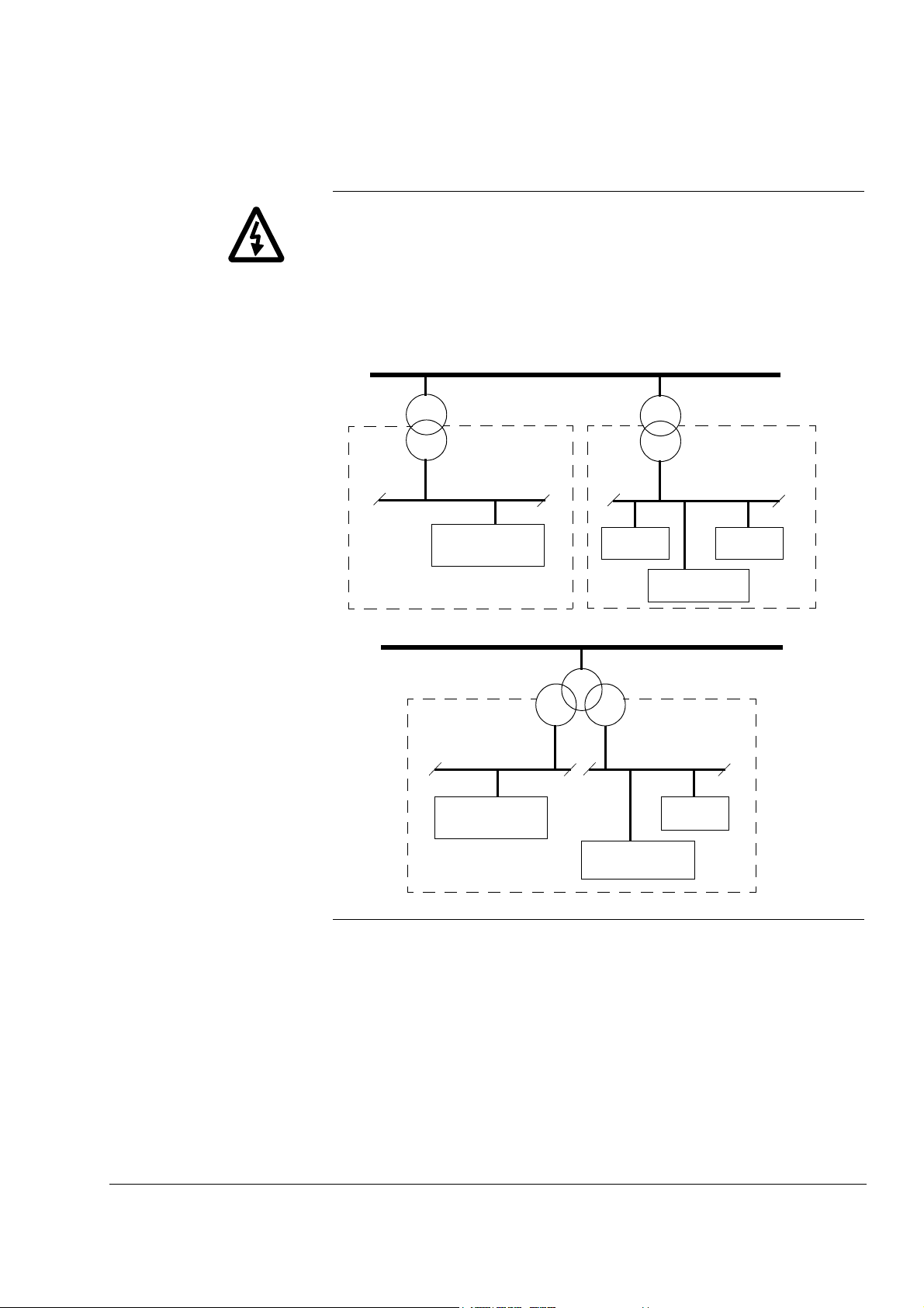
WARNING! Frame size R11i and above must be supplied with a
transformer dedicated to drives and motors or equipment of equal or
higher power, or with a transformer equipped with two secondary
windings, one of which is dedicated to drives and motors. Resonances
might occur if there is capacitive load (e.g. lighting, PC, PLC, small
power factor compensation capacitors) in the same network with the
drive. The resonance current might damage some unit in the network.
Medium voltage network
Supply transformer
Neighbouring network
Low voltage
Other load than
drives and motors
Medium voltage network
Other load than
drives and motors
or
Low voltage
Other drives and
motors
Motors
Other drives
Supply transformer
Drive
Low voltage
Drive
ACA 635 IGBT Supply Sections, ACS800-17 v
Page 8

Safety Instructions
vi ACA 635 IGBT Supply Sections, ACS800-17
Page 9

Table of Contents
ACS 600 MultiDrive Manuals (Air-cooled Units, English Originals)
Safety Instructions
Overview . . . . . . . . . . . . . . . . . . . . . . . . . . . . . . . . . . . . . . . . . . . . . . . . . . . . . . . . . . . . . . . . . . . . . iii
Installation and Maintenance Safety . . . . . . . . . . . . . . . . . . . . . . . . . . . . . . . . . . . . . . . . . . . . . . . . iii
Automatic Resets . . . . . . . . . . . . . . . . . . . . . . . . . . . . . . . . . . . . . . . . . . . . . . . . . . . . . . . . . . . . . . . iv
Dedicated Transformer . . . . . . . . . . . . . . . . . . . . . . . . . . . . . . . . . . . . . . . . . . . . . . . . . . . . . . . . . . . . v
Table of Contents
Update Notice for ACA 635 IGBT Supply Sections 260 to 4728 kVA
ACS 800-17 Line-side Converter 120 to 1385 kVA
ACS 800-17 Line-side Converter . . . . . . . . . . . . . . . . . . . . . . . . . . . . . . . . . . . . . . . . . . . . . . . . . . . .1
Chapter 1 - About this Manual . . . . . . . . . . . . . . . . . . . . . . . . . . . . . . . . . . . . . . . . . . . . . . . . . . . . . .1
Chapter 2 - Operation Basics . . . . . . . . . . . . . . . . . . . . . . . . . . . . . . . . . . . . . . . . . . . . . . . . . . . . . . .1
Chapter 3 - Hardware Description . . . . . . . . . . . . . . . . . . . . . . . . . . . . . . . . . . . . . . . . . . . . . . . . . . .2
Chapter 8 - Parameters . . . . . . . . . . . . . . . . . . . . . . . . . . . . . . . . . . . . . . . . . . . . . . . . . . . . . . . . . . .4
Appendix A - Technical Data . . . . . . . . . . . . . . . . . . . . . . . . . . . . . . . . . . . . . . . . . . . . . . . . . . . . . . .6
Appendix B Circuit Diagrams . . . . . . . . . . . . . . . . . . . . . . . . . . . . . . . . . . . . . . . . . . . . . . . . . . . . . .12
Chapter 1 – About this Manual
What this Chapter Contains . . . . . . . . . . . . . . . . . . . . . . . . . . . . . . . . . . . . . . . . . . . . . . . . . . . . . . . .1
Intended Audience . . . . . . . . . . . . . . . . . . . . . . . . . . . . . . . . . . . . . . . . . . . . . . . . . . . . . . . . . . . . . . .1
Parameter Setting . . . . . . . . . . . . . . . . . . . . . . . . . . . . . . . . . . . . . . . . . . . . . . . . . . . . . . . . . . . . . . .1
To which Products this Manual Applies . . . . . . . . . . . . . . . . . . . . . . . . . . . . . . . . . . . . . . . . . . . . . . .1
Contents . . . . . . . . . . . . . . . . . . . . . . . . . . . . . . . . . . . . . . . . . . . . . . . . . . . . . . . . . . . . . . . . . . . . . . .1
ISU-related Information in Other Manuals . . . . . . . . . . . . . . . . . . . . . . . . . . . . . . . . . . . . . . . . . . . . . 2
Chapter 2 – Operation Basics
Operation of ISU . . . . . . . . . . . . . . . . . . . . . . . . . . . . . . . . . . . . . . . . . . . . . . . . . . . . . . . . . . . . . . . . .1
Main Circuit Diagram . . . . . . . . . . . . . . . . . . . . . . . . . . . . . . . . . . . . . . . . . . . . . . . . . . . . . . . . . . . . .1
Control . . . . . . . . . . . . . . . . . . . . . . . . . . . . . . . . . . . . . . . . . . . . . . . . . . . . . . . . . . . . . . . . . . . . . . . .1
Voltage and Current Waveforms . . . . . . . . . . . . . . . . . . . . . . . . . . . . . . . . . . . . . . . . . . . . . . . . . . . .2
DC Current . . . . . . . . . . . . . . . . . . . . . . . . . . . . . . . . . . . . . . . . . . . . . . . . . . . . . . . . . . . . . . . . . . 2
Distortion . . . . . . . . . . . . . . . . . . . . . . . . . . . . . . . . . . . . . . . . . . . . . . . . . . . . . . . . . . . . . . . . . . . . . .3
Spectrum of the Voltage DIstortion . . . . . . . . . . . . . . . . . . . . . . . . . . . . . . . . . . . . . . . . . . . . . . . . 3
Spectrum of the Line Current Distortion . . . . . . . . . . . . . . . . . . . . . . . . . . . . . . . . . . . . . . . . . . . . 3
Chapter 3 – Hardware Description
Main Components of a Drive with ISU . . . . . . . . . . . . . . . . . . . . . . . . . . . . . . . . . . . . . . . . . . . . . . . .1
ACA 635 IGBT Supply Sections User’s Manual vii
Page 10

Supply Section . . . . . . . . . . . . . . . . . . . . . . . . . . . . . . . . . . . . . . . . . . . . . . . . . . . . . . . . . . . . . . . . . 1
Auxiliary Control Unit . . . . . . . . . . . . . . . . . . . . . . . . . . . . . . . . . . . . . . . . . . . . . . . . . . . . . . . . . . .2
Incoming Unit . . . . . . . . . . . . . . . . . . . . . . . . . . . . . . . . . . . . . . . . . . . . . . . . . . . . . . . . . . . . . . . . .2
Filter Unit . . . . . . . . . . . . . . . . . . . . . . . . . . . . . . . . . . . . . . . . . . . . . . . . . . . . . . . . . . . . . . . . . . . .2
IGBT Supply Unit . . . . . . . . . . . . . . . . . . . . . . . . . . . . . . . . . . . . . . . . . . . . . . . . . . . . . . . . . . . . . .4
Main Circuit Construction . . . . . . . . . . . . . . . . . . . . . . . . . . . . . . . . . . . . . . . . . . . . . . . . . . . . . . . . . 5
Configurations . . . . . . . . . . . . . . . . . . . . . . . . . . . . . . . . . . . . . . . . . . . . . . . . . . . . . . . . . . . . . . . . . . 5
Basic Configuration. . . . . . . . . . . . . . . . . . . . . . . . . . . . . . . . . . . . . . . . . . . . . . . . . . . . . . . . . . . . .5
Parallel Connected Modules . . . . . . . . . . . . . . . . . . . . . . . . . . . . . . . . . . . . . . . . . . . . . . . . . . . . .5
Braking Chopper. . . . . . . . . . . . . . . . . . . . . . . . . . . . . . . . . . . . . . . . . . . . . . . . . . . . . . . . . . . . . . .6
Chapter 4 – Commissioning the Supply Section with ISU
Overview . . . . . . . . . . . . . . . . . . . . . . . . . . . . . . . . . . . . . . . . . . . . . . . . . . . . . . . . . . . . . . . . . . . . . . 1
Installation Checklist . . . . . . . . . . . . . . . . . . . . . . . . . . . . . . . . . . . . . . . . . . . . . . . . . . . . . . . . . . . . . 1
Checks with No Voltage Connected . . . . . . . . . . . . . . . . . . . . . . . . . . . . . . . . . . . . . . . . . . . . . . . . . 2
Connecting Voltage to Auxiliary Circuits . . . . . . . . . . . . . . . . . . . . . . . . . . . . . . . . . . . . . . . . . . . . . . 3
Checks with Voltage Connected to Auxiliary Circuits . . . . . . . . . . . . . . . . . . . . . . . . . . . . . . . . . . . . .4
Connecting Voltage to IGBT Supply Unit . . . . . . . . . . . . . . . . . . . . . . . . . . . . . . . . . . . . . . . . . . . . . 5
Starting . . . . . . . . . . . . . . . . . . . . . . . . . . . . . . . . . . . . . . . . . . . . . . . . . . . . . . . . . . . . . . . . . . . . . . . 6
Checks with ISU Supply Started . . . . . . . . . . . . . . . . . . . . . . . . . . . . . . . . . . . . . . . . . . . . . . . . . . . . 7
Parameters . . . . . . . . . . . . . . . . . . . . . . . . . . . . . . . . . . . . . . . . . . . . . . . . . . . . . . . . . . . . . . . . . . . . 7
Controlling the ISU with an Overriding System . . . . . . . . . . . . . . . . . . . . . . . . . . . . . . . . . . . . . . . . .8
Fieldbus Adapters . . . . . . . . . . . . . . . . . . . . . . . . . . . . . . . . . . . . . . . . . . . . . . . . . . . . . . . . . . . . . . . 9
On-load Checks . . . . . . . . . . . . . . . . . . . . . . . . . . . . . . . . . . . . . . . . . . . . . . . . . . . . . . . . . . . . . . . . . 9
Chapter 5 – Earth Fault Protection
Overview . . . . . . . . . . . . . . . . . . . . . . . . . . . . . . . . . . . . . . . . . . . . . . . . . . . . . . . . . . . . . . . . . . . . . . 1
Floating Network . . . . . . . . . . . . . . . . . . . . . . . . . . . . . . . . . . . . . . . . . . . . . . . . . . . . . . . . . . . . . . . . 1
Insulation Monitoring Device . . . . . . . . . . . . . . . . . . . . . . . . . . . . . . . . . . . . . . . . . . . . . . . . . . . . .1
System-earthed Network . . . . . . . . . . . . . . . . . . . . . . . . . . . . . . . . . . . . . . . . . . . . . . . . . . . . . . . . . . 2
Chapter 6 – Firmware Description
Overview . . . . . . . . . . . . . . . . . . . . . . . . . . . . . . . . . . . . . . . . . . . . . . . . . . . . . . . . . . . . . . . . . . . . . . 1
Control Principle . . . . . . . . . . . . . . . . . . . . . . . . . . . . . . . . . . . . . . . . . . . . . . . . . . . . . . . . . . . . . . . . 1
Identification Routine . . . . . . . . . . . . . . . . . . . . . . . . . . . . . . . . . . . . . . . . . . . . . . . . . . . . . . . . . . . . . 3
Charging . . . . . . . . . . . . . . . . . . . . . . . . . . . . . . . . . . . . . . . . . . . . . . . . . . . . . . . . . . . . . . . . . . . . . . 4
Synchronization . . . . . . . . . . . . . . . . . . . . . . . . . . . . . . . . . . . . . . . . . . . . . . . . . . . . . . . . . . . . . . . . . 4
Starting Sequence . . . . . . . . . . . . . . . . . . . . . . . . . . . . . . . . . . . . . . . . . . . . . . . . . . . . . . . . . . . . . . . 5
Start by the Starting Switch . . . . . . . . . . . . . . . . . . . . . . . . . . . . . . . . . . . . . . . . . . . . . . . . . . . . . .6
Start via Fieldbus . . . . . . . . . . . . . . . . . . . . . . . . . . . . . . . . . . . . . . . . . . . . . . . . . . . . . . . . . . . . . .7
Stop . . . . . . . . . . . . . . . . . . . . . . . . . . . . . . . . . . . . . . . . . . . . . . . . . . . . . . . . . . . . . . . . . . . . . . . . . . 8
Missing Phase . . . . . . . . . . . . . . . . . . . . . . . . . . . . . . . . . . . . . . . . . . . . . . . . . . . . . . . . . . . . . . . . . . 8
Control Diagram . . . . . . . . . . . . . . . . . . . . . . . . . . . . . . . . . . . . . . . . . . . . . . . . . . . . . . . . . . . . . . . . 9
Controllers . . . . . . . . . . . . . . . . . . . . . . . . . . . . . . . . . . . . . . . . . . . . . . . . . . . . . . . . . . . . . . . . . . . . . 9
DC Voltage Controller. . . . . . . . . . . . . . . . . . . . . . . . . . . . . . . . . . . . . . . . . . . . . . . . . . . . . . . . . .10
Reactive Power Control . . . . . . . . . . . . . . . . . . . . . . . . . . . . . . . . . . . . . . . . . . . . . . . . . . . . . . . .11
viii ACA 635 IGBT Supply Sections User’s Manual
Page 11

Chapter 7 – Fault Tracing
Overview . . . . . . . . . . . . . . . . . . . . . . . . . . . . . . . . . . . . . . . . . . . . . . . . . . . . . . . . . . . . . . . . . . . . . .1
Fault Tracing . . . . . . . . . . . . . . . . . . . . . . . . . . . . . . . . . . . . . . . . . . . . . . . . . . . . . . . . . . . . . . . . . . .1
Fault Resetting . . . . . . . . . . . . . . . . . . . . . . . . . . . . . . . . . . . . . . . . . . . . . . . . . . . . . . . . . . . . . . . 1
Fault History . . . . . . . . . . . . . . . . . . . . . . . . . . . . . . . . . . . . . . . . . . . . . . . . . . . . . . . . . . . . . . . . . 2
Fault and Warning Messages . . . . . . . . . . . . . . . . . . . . . . . . . . . . . . . . . . . . . . . . . . . . . . . . . . . . 2
What to Do in Case of an Earth Fault Indication . . . . . . . . . . . . . . . . . . . . . . . . . . . . . . . . . . . . . . . . 6
Flowchart. . . . . . . . . . . . . . . . . . . . . . . . . . . . . . . . . . . . . . . . . . . . . . . . . . . . . . . . . . . . . . . . . . . . 7
Chapter 8 – Parameters
Overview . . . . . . . . . . . . . . . . . . . . . . . . . . . . . . . . . . . . . . . . . . . . . . . . . . . . . . . . . . . . . . . . . . . . . .1
1 Actual Signals . . . . . . . . . . . . . . . . . . . . . . . . . . . . . . . . . . . . . . . . . . . . . . . . . . . . . . . . . . . . . . . . .2
2 Actual Signals . . . . . . . . . . . . . . . . . . . . . . . . . . . . . . . . . . . . . . . . . . . . . . . . . . . . . . . . . . . . . . . . .3
3 Actual Signals . . . . . . . . . . . . . . . . . . . . . . . . . . . . . . . . . . . . . . . . . . . . . . . . . . . . . . . . . . . . . . . . .3
4 Information . . . . . . . . . . . . . . . . . . . . . . . . . . . . . . . . . . . . . . . . . . . . . . . . . . . . . . . . . . . . . . . . . . .4
7 Control Word . . . . . . . . . . . . . . . . . . . . . . . . . . . . . . . . . . . . . . . . . . . . . . . . . . . . . . . . . . . . . . . . . .5
8 Status Word . . . . . . . . . . . . . . . . . . . . . . . . . . . . . . . . . . . . . . . . . . . . . . . . . . . . . . . . . . . . . . . . . . .5
9 Fault Words . . . . . . . . . . . . . . . . . . . . . . . . . . . . . . . . . . . . . . . . . . . . . . . . . . . . . . . . . . . . . . . . . . .6
11 Reference Selects . . . . . . . . . . . . . . . . . . . . . . . . . . . . . . . . . . . . . . . . . . . . . . . . . . . . . . . . . . . . .9
13 Analogue Inputs . . . . . . . . . . . . . . . . . . . . . . . . . . . . . . . . . . . . . . . . . . . . . . . . . . . . . . . . . . . . . .9
14 Digital Outputs . . . . . . . . . . . . . . . . . . . . . . . . . . . . . . . . . . . . . . . . . . . . . . . . . . . . . . . . . . . . . . .10
15 Analogue Outputs . . . . . . . . . . . . . . . . . . . . . . . . . . . . . . . . . . . . . . . . . . . . . . . . . . . . . . . . . . . .11
16 System Control Inputs . . . . . . . . . . . . . . . . . . . . . . . . . . . . . . . . . . . . . . . . . . . . . . . . . . . . . . . . .12
18 LED Panel Control . . . . . . . . . . . . . . . . . . . . . . . . . . . . . . . . . . . . . . . . . . . . . . . . . . . . . . . . . . . .13
19 Data Storage . . . . . . . . . . . . . . . . . . . . . . . . . . . . . . . . . . . . . . . . . . . . . . . . . . . . . . . . . . . . . . . .14
Trend Monitoring with Drive Window . . . . . . . . . . . . . . . . . . . . . . . . . . . . . . . . . . . . . . . . . . . . . 14
Sending a value. . . . . . . . . . . . . . . . . . . . . . . . . . . . . . . . . . . . . . . . . . . . . . . . . . . . . . . . . . . . . . 14
19 Data Storage Parameter Table . . . . . . . . . . . . . . . . . . . . . . . . . . . . . . . . . . . . . . . . . . . . . . . 15
21 Start/Stop Functions . . . . . . . . . . . . . . . . . . . . . . . . . . . . . . . . . . . . . . . . . . . . . . . . . . . . . . . . . .16
23 DC Bus Reference . . . . . . . . . . . . . . . . . . . . . . . . . . . . . . . . . . . . . . . . . . . . . . . . . . . . . . . . . . .18
Example. . . . . . . . . . . . . . . . . . . . . . . . . . . . . . . . . . . . . . . . . . . . . . . . . . . . . . . . . . . . . . . . . . . . 18
24 Reactive Power . . . . . . . . . . . . . . . . . . . . . . . . . . . . . . . . . . . . . . . . . . . . . . . . . . . . . . . . . . . . . . 18
30 Fault Functions . . . . . . . . . . . . . . . . . . . . . . . . . . . . . . . . . . . . . . . . . . . . . . . . . . . . . . . . . . . . . .19
51 Communication Module . . . . . . . . . . . . . . . . . . . . . . . . . . . . . . . . . . . . . . . . . . . . . . . . . . . . . . . .20
70 DDCS Control . . . . . . . . . . . . . . . . . . . . . . . . . . . . . . . . . . . . . . . . . . . . . . . . . . . . . . . . . . . . . . .20
71 DriveBus Communication . . . . . . . . . . . . . . . . . . . . . . . . . . . . . . . . . . . . . . . . . . . . . . . . . . . . . .22
90, 91 Data Set Receive Addresses . . . . . . . . . . . . . . . . . . . . . . . . . . . . . . . . . . . . . . . . . . . . . . . .23
92, 93 Data Set Transmit Addresses . . . . . . . . . . . . . . . . . . . . . . . . . . . . . . . . . . . . . . . . . . . . . . . .24
98 Option Modules . . . . . . . . . . . . . . . . . . . . . . . . . . . . . . . . . . . . . . . . . . . . . . . . . . . . . . . . . . . . . . 25
99 Start-up Data . . . . . . . . . . . . . . . . . . . . . . . . . . . . . . . . . . . . . . . . . . . . . . . . . . . . . . . . . . . . . . . .26
Appendix A – Technical Data
Ratings . . . . . . . . . . . . . . . . . . . . . . . . . . . . . . . . . . . . . . . . . . . . . . . . . . . . . . . . . . . . . . . . . . . . . . . .1
Abbreviations. . . . . . . . . . . . . . . . . . . . . . . . . . . . . . . . . . . . . . . . . . . . . . . . . . . . . . . . . . . . . . . . . 1
Notes . . . . . . . . . . . . . . . . . . . . . . . . . . . . . . . . . . . . . . . . . . . . . . . . . . . . . . . . . . . . . . . . . . . . . . . 1
Ratings 380...690 V. . . . . . . . . . . . . . . . . . . . . . . . . . . . . . . . . . . . . . . . . . . . . . . . . . . . . . . . . . . . 2
Dimensions and Weights . . . . . . . . . . . . . . . . . . . . . . . . . . . . . . . . . . . . . . . . . . . . . . . . . . . . . . . . . .3
ACA 635 IGBT Supply Sections User’s Manual ix
Page 12

Input Power Connection . . . . . . . . . . . . . . . . . . . . . . . . . . . . . . . . . . . . . . . . . . . . . . . . . . . . . . . . . . 4
Harmonic Distortion . . . . . . . . . . . . . . . . . . . . . . . . . . . . . . . . . . . . . . . . . . . . . . . . . . . . . . . . . . . .5
Switching Frequency . . . . . . . . . . . . . . . . . . . . . . . . . . . . . . . . . . . . . . . . . . . . . . . . . . . . . . . . . . . . . 5
Ambient Conditions . . . . . . . . . . . . . . . . . . . . . . . . . . . . . . . . . . . . . . . . . . . . . . . . . . . . . . . . . . . . . . 5
Efficiency . . . . . . . . . . . . . . . . . . . . . . . . . . . . . . . . . . . . . . . . . . . . . . . . . . . . . . . . . . . . . . . . . . . . . . 5
Fuses . . . . . . . . . . . . . . . . . . . . . . . . . . . . . . . . . . . . . . . . . . . . . . . . . . . . . . . . . . . . . . . . . . . . . . . . . 6
IGBT Supply Section AC Fuses . . . . . . . . . . . . . . . . . . . . . . . . . . . . . . . . . . . . . . . . . . . . . . . . . . .6
IGBT Supply Unit DC Fuses . . . . . . . . . . . . . . . . . . . . . . . . . . . . . . . . . . . . . . . . . . . . . . . . . . . . .7
Power Cable Entries . . . . . . . . . . . . . . . . . . . . . . . . . . . . . . . . . . . . . . . . . . . . . . . . . . . . . . . . . . . . . 7
Tightening Torque. . . . . . . . . . . . . . . . . . . . . . . . . . . . . . . . . . . . . . . . . . . . . . . . . . . . . . . . . . . . . .7
Marking. . . . . . . . . . . . . . . . . . . . . . . . . . . . . . . . . . . . . . . . . . . . . . . . . . . . . . . . . . . . . . . . . . . . . .7
IGBT Supply Sections. . . . . . . . . . . . . . . . . . . . . . . . . . . . . . . . . . . . . . . . . . . . . . . . . . . . . . . . . . .8
Drive Control Unit NDCU-51 . . . . . . . . . . . . . . . . . . . . . . . . . . . . . . . . . . . . . . . . . . . . . . . . . . . . . . . 9
NIOC Board Connections . . . . . . . . . . . . . . . . . . . . . . . . . . . . . . . . . . . . . . . . . . . . . . . . . . . . . . . . 10
NIOC Board Specifications . . . . . . . . . . . . . . . . . . . . . . . . . . . . . . . . . . . . . . . . . . . . . . . . . . . . . . . 11
Drive Control Unit RDCU . . . . . . . . . . . . . . . . . . . . . . . . . . . . . . . . . . . . . . . . . . . . . . . . . . . . . . . . . 12
Motor Control and I/O board RMIO-01 . . . . . . . . . . . . . . . . . . . . . . . . . . . . . . . . . . . . . . . . . . . . . . 14
RMIO board specifications . . . . . . . . . . . . . . . . . . . . . . . . . . . . . . . . . . . . . . . . . . . . . . . . . . . . . . . 16
Applicable Standards . . . . . . . . . . . . . . . . . . . . . . . . . . . . . . . . . . . . . . . . . . . . . . . . . . . . . . . . . . . 17
CE Marking . . . . . . . . . . . . . . . . . . . . . . . . . . . . . . . . . . . . . . . . . . . . . . . . . . . . . . . . . . . . . . . . . . . 17
Definitions. . . . . . . . . . . . . . . . . . . . . . . . . . . . . . . . . . . . . . . . . . . . . . . . . . . . . . . . . . . . . . . . . . .17
Compliance with the EMC Directive . . . . . . . . . . . . . . . . . . . . . . . . . . . . . . . . . . . . . . . . . . . . . .18
Machinery Directive . . . . . . . . . . . . . . . . . . . . . . . . . . . . . . . . . . . . . . . . . . . . . . . . . . . . . . . . . . .18
Appendix B – Circuit Diagrams
Overview . . . . . . . . . . . . . . . . . . . . . . . . . . . . . . . . . . . . . . . . . . . . . . . . . . . . . . . . . . . . . . . . . . . . . . 1
x ACA 635 IGBT Supply Sections User’s Manual
Page 13
Update Notice for
ACA 635 IGBT Supply Sections 260 to 4728 kVA
ACS 800-17 Line-side Converter 120 to 1385 kVA
The notice concerns The translation (DE revision C) of the ACA 635 IGBT Supply Sections
260 to 4728 kVA, ACS 800-17 Line-side Converter 120 to 1385 kVA
User’s Manual: code 3BFE 64495062
The notice is in use from 28.07.2003
The notice contains Updates to the REV C translation.
ACS 800-17 Line-side
Converter
Chapter 1 - About this
Manual
Chapter 2 - Operation
Basics
CHANGED: ACS/ACC 617 line-side converter has been replaced by
the ACS 800-17 line-side converter.
Page 1-2, User Interface CHANGED: The user interface of the IGBT
Supply Unit is a CDP 312 Control Panel or a PC, which is equipped
with a DDCS board and DriveWindow.
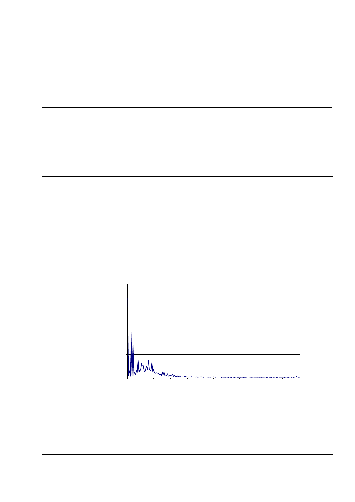
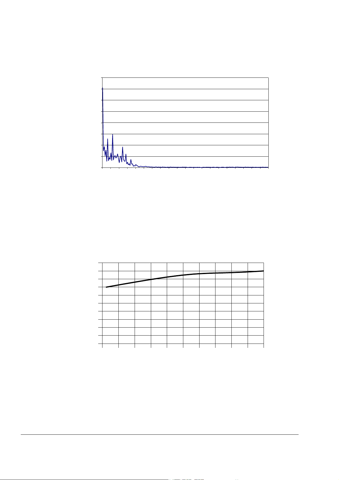
Page 2-3 CHANGED: Voltage and current distortion
Spectrum of the Voltage Distortion
2
1,5
1
0,5
0
THD 11 21 31 41 51 61 71 81 91 101 111 121 131 141 151 161 171 181 191
Update notice 1
Page 14
Update Notice
Spectrum of the Current Distortion
4
3,5
3
2,5
2
1,5
1
0,5
0
THD 11 21 31 41 51 61 71 81 91 101 111 121 131 141 151 161 171 181 191
Chapter 3 - Hardware
Description
Current THD [%]
Page 3-2, Incoming Unit CHANGED: Frames R6i to R9i: switch fuse
(including AC fuses) and main contactor. Frames R11i and above: air
circuit breaker.
Page 3-3 CHANGED: Current and voltage distortion
Current Distortion (up to 200th) Generated by the Supply Unit at
PCC (Point of Common Coupling)
5
4.5
4
3.5
3
2.5
2
1.5
1
0.5
0
0 102030405060708090100
Rsc (Short-circuit Ratio) at PCC
2 Update notice
Page 15
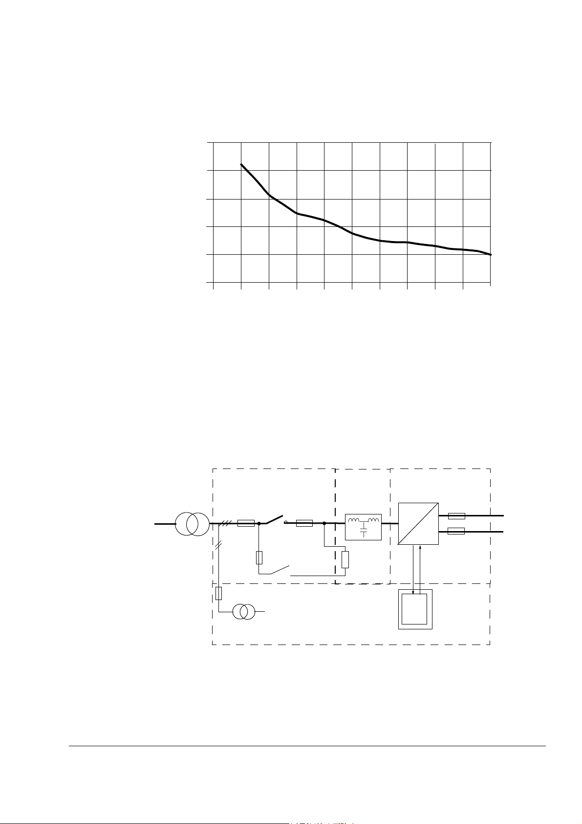
Voltage THD [%]
Update Notice
Voltage Distortion (up to 200th) Generated by the Supply Unit at
PCC (Point of Common Coupling)
5
4
3
2
1
0
0 102030405060708090100
Rsc (Short-circuit Ratio) at PCC
Page 3-5 Basic Configuration CHANGED:
The hardware of the IGBT supply unit is similar to the hardware of the
ACS 600 MultiDrive inverter. One NAMC/RMIO board controls the
converter module. It is located inside the Drive Control Unit (NDCU/
RDCU) box. The supply section is equipped with an LCL filter, DC
fuses and AC fuses/switch fuse OESA. AC fuses are used with a
breaker and a switch fuse is used with a contactor.
ISUICU
OESA
FIU
Converter
Module
AC fuses DC fuses
~
=
Charging circuit
230/115 V
NAMC/
RMIO
NDCU/RDCU
ACU
Update notice 3
Page 16

Update Notice
Chapter 8 - Parameters
Page 8-2 CHANGED:
Code Parameter Range/Unit Description Integer Scaling
1 ACTUAL
SIGNALS
1.19 AI1 [V]
0...10 Non-scaled value of analogue input
AI1. See Par. 13.01 AI1 HIGH
VALUE and 13.02 AI1 LOW VALUE.
10000 = 10 V or
20 mA
Page 8-4 CHANGED:
The software version (Parameters 4.01 and 4.03) is expressed as
follows:
Character noExample Meaning
1 I I = Input bridge software
2 X Product: X= ISU
3 X Software type:
A = application software (Parameter 4.03)
4 G Control board: G = NAMC-51, R = RMIO
5 to 8 6000 Software version number: 6000 = NAMC-51,
7000 = RMIO
Page 8-9 ADDED:
Code Parameter T
13 ANALOGUE
INPUTS
13.12 MINIMUM
AI1
Default Alternative
y
p
e
I0 V (1) 0 V
Settings
( ) Fieldbus
Equivalent
(2) -10 V
Description Integer
Scaling
This value corresponds to the
minimum reference from
analogue input AI1.
4 Update notice
Page 17

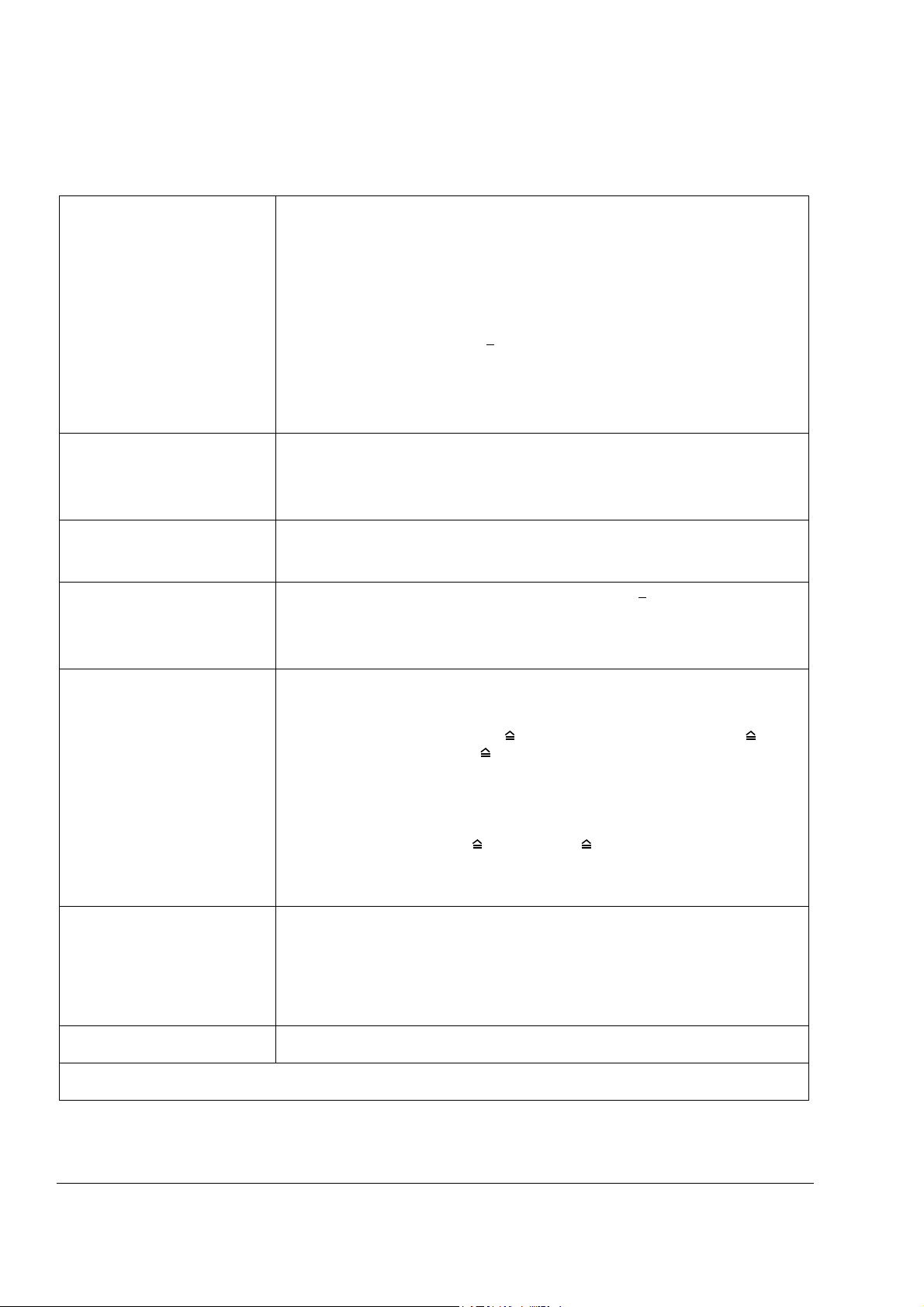
Page 8-22 CHANGED:
Update Notice
Code Parameter
70 DDCS
CONTROL
70.20 CH3 HW
CONNECTION
T
Default Alternative
y
p
e
B
STAR This parameter is used for
Settings
( ) Fieldbus
Equivalent
(0) RING Regeneration enabled. Select
(1) STAR Regeneration disabled.
Description Integer
enabling or disabling
regeneration of channel CH3
optical transmitter. In
regeneration mode any
message received by the
channel is echoed back.
RING if the CH3 channels on
the NAMC boards / RDCO
modules are connected to a
ring configuration.
Select STAR with a star
configuration such as
DriveWindow (PC) – NDBU95 optical branching unit(s) –
NAMC board / RDCO module
(RMIO board).
Scaling
1=1
Page 8-23 CHANGED: D SET 10 VAL 1 denotes the receive address
of data set 10 value 1.
Page 8-24 CHANGED: D SET 11 VAL 1 denotes the transmit address
of data set 11 value 1.
Update notice 5
Page 18
Update Notice
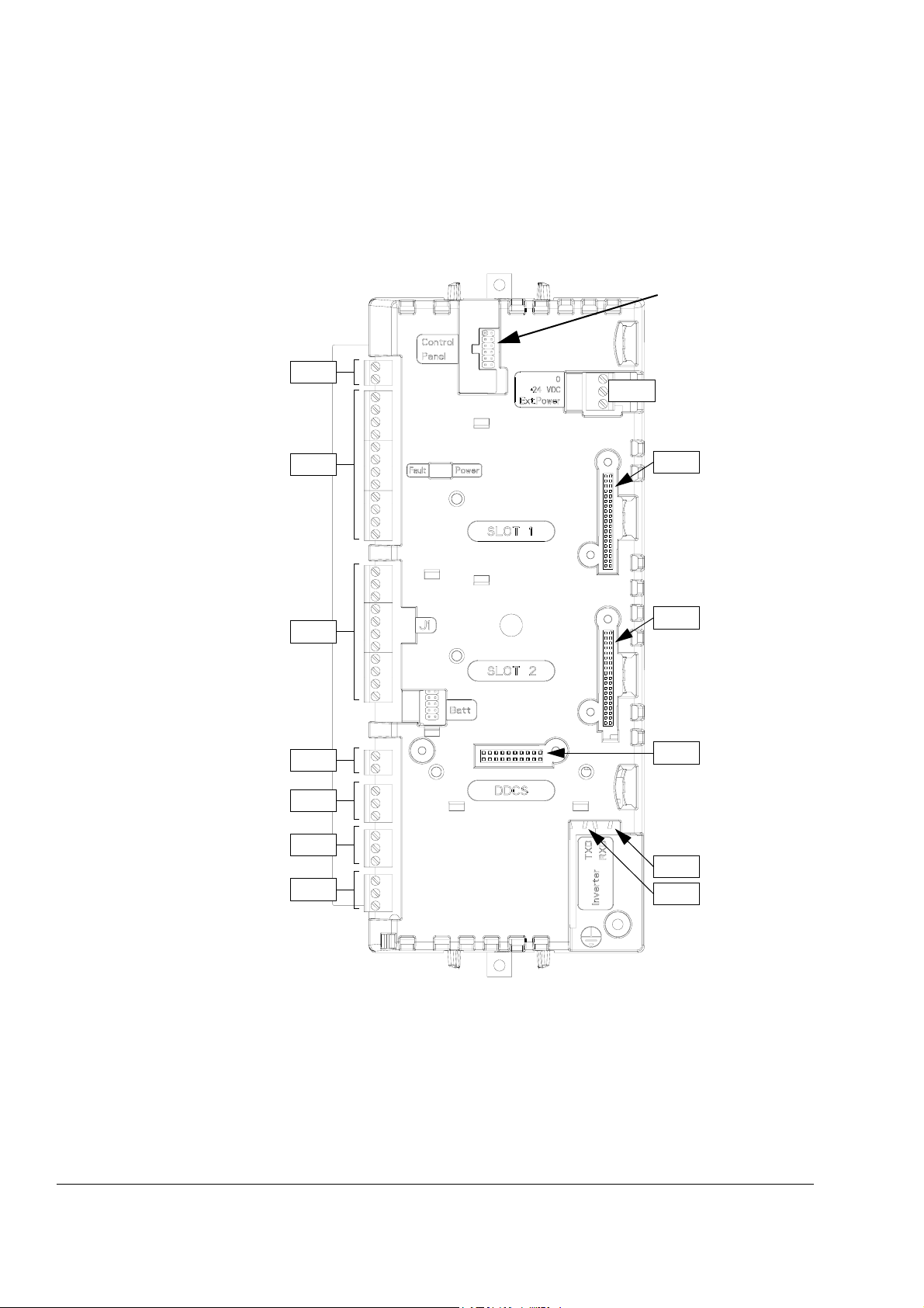
Appendix A Technical Data
Page A-9 ADDED: Drive Control Unit RDCU has been added to the
manual. The RDCU unit replaces the NDCU-51 unit. The Drive Control
Unit RDCU containing an RMIO-01 board is shown in the pictures
below.
Interface for
CDP312
Control Panel
X20
X34
X21
X31
X22
X23
X25
X26
X27
X32
X33
X68
X57
6 Update notice
Page 19

Update Notice
Update notice 7
Page 20
Update Notice
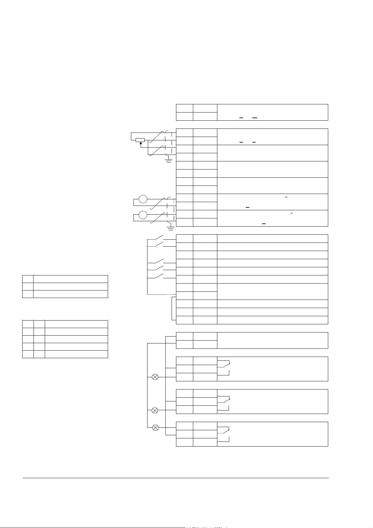
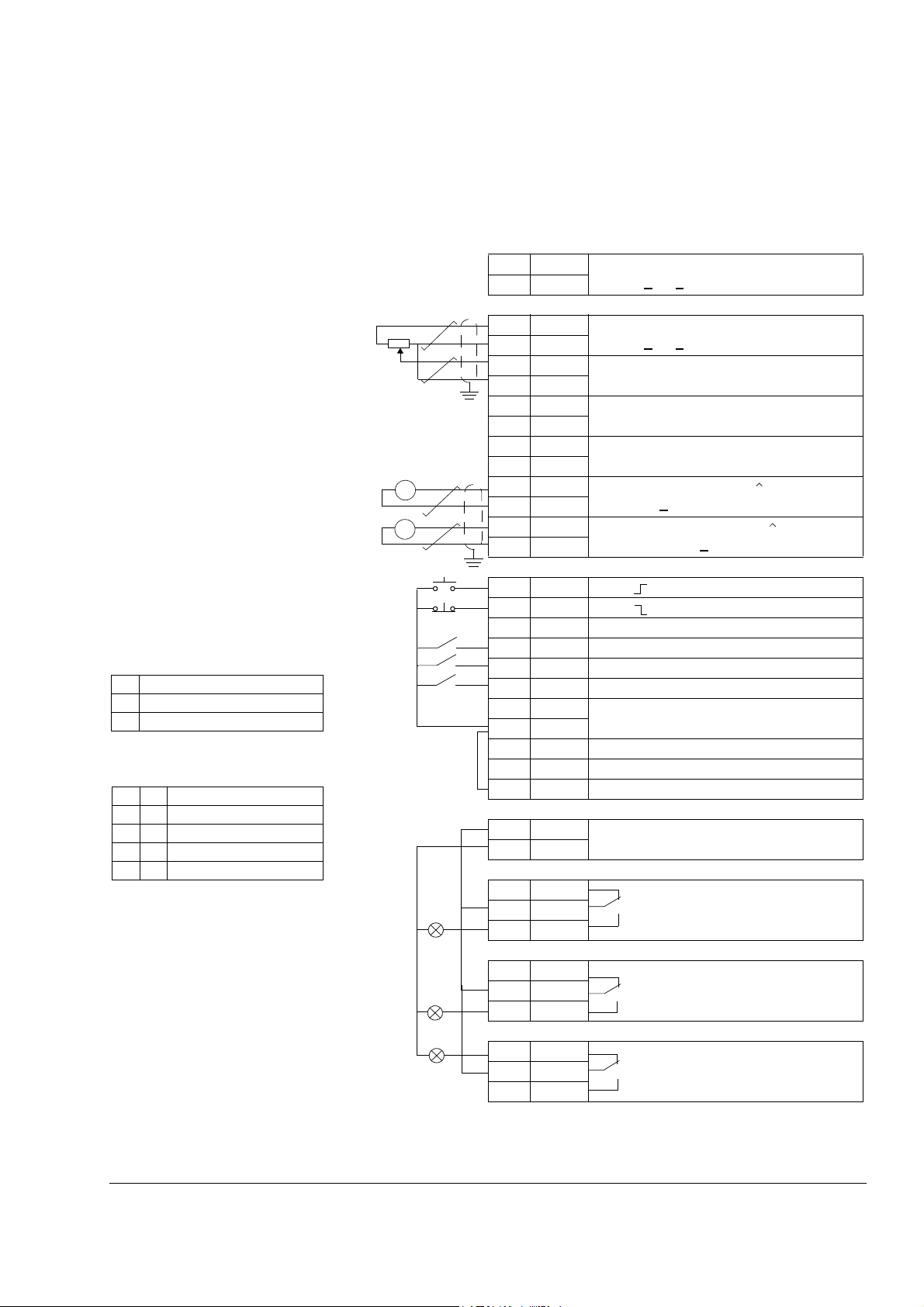
External control cable connections (non-US) to the RMIO board for the
ACS 800 Standard Application Program (Factory Macro) are shown
below. For external control connections of other application macros
and programs, see the appropriate Firmware Manual.
Terminal block size:
cables 0.3 to 3.3 mm2 (22 to 12 AWG)
Tightening torque:
0.2 to 0.4 Nm (2 to 4 lbf in.)
1)
Only effective if par. 10.03 is set to
REQUEST by the user.
2)
0 = open, 1 = closed
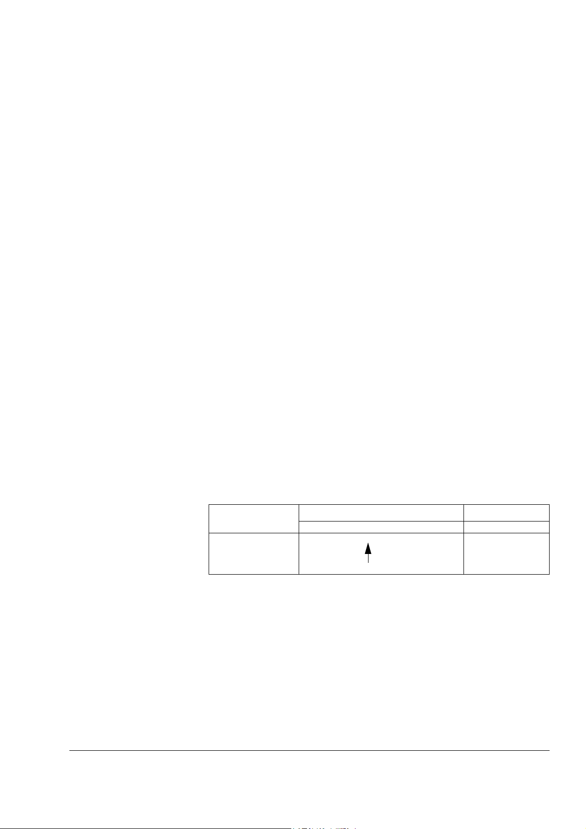
DI4 Ramp times according to
0 parameters 22.02 and 22.03
1 parameters 22.04 and 22.05
3)
See par. group 12 CONSTANT
SPEEDS.
DI5 DI6 Operation
0 0 Set speed through AI1
1 0 Constant speed 1
0 1 Constant speed 2
1 1 Constant speed 3
4)
See parameter 21.09 START INTRL
FUNC.
rpm
A
Fault
X20
1 VREF- Reference voltage -10 VDC,
2 GND
1 kohm <
RL< 10 kohm
X21
1 VREF+ Reference voltage 10 VDC,
2GND
1 kohm <
RL< 10 kohm
3 AI1+ Speed reference 0(2) ... 10 V,
> 200 kohm
4AI1-
R
in
5 AI2+ By default, not in use. 0(4) ... 20 mA,
= 100 ohm
6AI2-
R
in
7 AI3+ By default, not in use. 0(4) ... 20 mA,
= 100 ohm
8AI39 AO1+ Motor speed 0(4)...20 mA 0...motor nom.
10 AO111 AO2+ Output current 0(4)...20 mA 0...motor
12 AO2-
R
in
speed, R
< 700 ohm
L
nom. current, R
< 700 ohm
L
=
=
X22
1DI1 Stop/Start
2 DI2 Forward/Reverse
1)
3 DI3 Not in use
4 DI4 Acceleration & deceleration select
5 DI5 Constant speed select
6 DI6 Constant speed select
3)
3)
2)
7 +24V +24 VDC max. 100 mA
8 +24V
9 DGND Digital ground
10 DGND Digital ground
11 DIIL Start interlock (0 = stop)
4)
X23
1 +24V Auxiliary voltage output, non-isolated,
2GND
24 VDC 250 mA
X25
1 RO11 Relay output 1: ready
2RO12
3RO13
X26
1 RO21 Relay output 2: running
2RO22
3RO23
X27
1 RO31 Relay output 3: fault (-1)
2RO32
3RO33
External control cable connections (US) to the RMIO board for the
8 Update notice
Page 21
Terminal block size:
cables 0.3 to 3.3 mm
2
(22 to 12 AWG)
Tightening torque:
0.2 to 0.4 Nm (2 to 4 lbf in.)
1)
Only effective if par. 10.03 is set to
REQUEST by the user.
2)
0 = open, 1 = closed
DI4 Ramp times according to
0 parameters 22.02 and 22.03
1 parameters 22.04 and 22.05
3)
See par. group 12 CONSTANT
SPEEDS.
DI5 DI6 Operation
0 0 Set speed through AI1
1 0 Constant speed 1
0 1 Constant speed 2
1 1 Constant speed 3
4)
See parameter 21.09 START INTRL
FUNC.
Update Notice
ACS800 Standard Application Program (Factory Macro US version,
+N665) are shown below. For external control connections of other
application macros and programs, see the appropriate Firmware
Manual.
X20
1 VREF- Reference voltage -10 VDC,
RL< 10 kohm
RL< 10 kohm
> 200 kohm
= 100 ohm
= 100 ohm
< 700 ohm
L
< 700 ohm
L
1)
=
=
2)
3)
3)
4)
rpm
A
Fault
2 GND
1kohm<
X21
1 VREF+ Reference voltage 10 VDC,
2GND
1kohm<
3 AI1+ Speed reference 0(2) ... 10 V,
4AI1-
R
in
5 AI2+ By default, not in use. 0(4) ... 20 mA,
6AI2-
R
in
7 AI3+ By default, not in use. 0(4) ... 20 mA,
8AI3-
R
in
9 AO1+ Motor speed 0(4)...20 mA 0...motor nom.
10 AO1-
speed, R
11 AO2+ Output current 0(4)...20 mA 0...motor
12 AO2-
nom. current, R
X22
1DI1 Start ()
2 DI2 Stop ( )
3 DI3 Forward/Reverse
4 DI4 Acceleration & deceleration select
5 DI5 Constant speed select
6 DI6 Constant speed select
7 +24V +24 VDC max. 100 mA
8+24V
9 DGND Digital ground
10 DGND Digital ground
11 DIIL Start interlock (0 = stop)
X23
1 +24V Auxiliary voltage output, non-isolated,
2GND
24 VDC 250 mA
X25
1 RO11 Relay output 1: ready
2RO12
3RO13
X26
1 RO21 Relay output 2: running
2RO22
3RO23
X27
1 RO31 Relay output 3: fault (-1)
2RO32
3RO33
Update notice 9
Page 22
Update Notice
RMIO Board Specifications
Analogue inputs With Standard Application Program two programmable differential current inputs
(0 mA / 4 mA ... 20 mA, R
input (-10 V / 0 V / 2 V ... +10 V, R
The analogue inputs are galvanically isolated as a group.
Isolation Test voltage: 500 VAC, 1 min
Max. common mode voltage between the channels: ±15 VDC
Common mode rejection ratio: >
Resolution: 0.025% (12 bit) for the -10 V ... +10 V input. 0.5% (11 bit) for the 0 ... +10
V and 0 ... 20 mA inputs.
Inaccuracy: ± 0.5% (Full Scale Range) at 25 °C. Temperature coefficient: ± 100 ppm/
°C, max.
Constant voltage output Voltage: +10 VDC, 0, -10 VDC ± 0.5% (Full Scale Range) at 25 °C. Temperature
coefficient: ± 100 ppm/°C (± 56 ppm/°F) max
Maximum load: 10 mA
Applicable potentiometer: 1 kohm to 10 kohm
Auxiliary power output Voltage: 24 VDC ± 10%, short circuit proof
Maximum current: 250 mA (without any optional modules inserted onto slots 1 and
2)
Analogue outputs Two programmable current outputs: 0 (4) to 20 mA, R
Resolution: 0.1% (10 bit)
Inaccuracy: ± 1% (Full Scale Range) at 25 °C (77 °F). Temperature coefficient:
± 200 ppm/°C (± 111 ppm/°F) max.
Digital inputs With Standard Application Program six programmable digital inputs (common ground:
24 VDC, -15% to +20%) and a start interlock input. Group isolated, can be divided in
two isolated groups (see Isolation and grounding diagram below).
Thermistor input: 5 mA, < 1.5 kohm “1” (normal temperature), > 4 kohm “0”
(high temperature), open circuit “0” (high temperature).
Internal supply for digital inputs (+24 VDC): short circuit proof. An external 24 VDC
supply can be used instead of the internal supply.
Isolation test voltage: 500 VAC, 1 min
Logical thresholds: < 8 VDC “0”, > 12 VDC “1”
Input current: DI1 to DI 5: 10 mA, DI6: 5 mA
Filtering time constant: 1ms
Relay outputs Three programmable relay outputs
Switching capacity: 8 A at 24 VDC or 250 VAC, 0.4 A at 120 VDC
Minimum continuous current: 5 mA rms at 24 VDC
Maximum continuous current: 2 A rms
Isolation test voltage: 4 kVAC, 1 minute
DDCS fibre optic link With optional communication adapter module RDCO. Protocol: DDCS (ABB
Distributed Drives Communication System)
The RMIO board as well as the optional modules attachable to the board fulfil the Protective Extra Low Voltage (PELV)
requirements stated in EN 50178.
= 100 ohm) and one programmable differential voltage
in
> 200 kohm).
in
60 dB at 50 Hz
< 700 ohm
L
10 Update notice
Page 23
Update Notice
Page A-12 CHANGED:
• EN 61800-3: 1996, Amendment A11: 2000 (IEC 61800-3). EMC
product standard including specific test method
Page A-13, Second Environment CHANGED:
The ACA 635 supply sections comply with the EMC Directive in
industrial low-voltage network, and IT networks (unearthed mains) with
the following provisions. For ACS800-17 units, refer to ACS800-17
Hardware Manual (EN code 64638505).
1. The motor and control cables are selected as specified in the
Hardware Manual.
2. The drive is installed according to the instructions given in the
Hardware Manual.
3. Maximum cable length is 100 metres.
WARNING! The drive may cause radio interference if used in a
residential or domestic environment. The user is required to take
measures to prevent interference, in addition to the requirements for
CE compliance listed above, if necessary.
Note: It is not allowed to use EMC filters on an unearthed mains supply
network, unless the filters are able to withstand the unearthed network.
(EMC filters are used to minimise the RFI emission of the unit.)
Note: With cables longer than 100 metres, the ACA 635 supply
sections comply with the EMC Directive in restricted distribution mode
when the installation is described in an EMC plan (a template is
available from the local ABB representative).
Table A-1 The EMC cabinet option is marked in the type code as
follows. 0 = No EMC cabinet, 1 = EMC cabinet (does not include RFI
filters)
ACS 600 Type
ACA 635
Character no. Options
ACA635xxxxxxxxxxxx...
16
Type Code
0,1
Update notice 11
Page 24
Update Notice
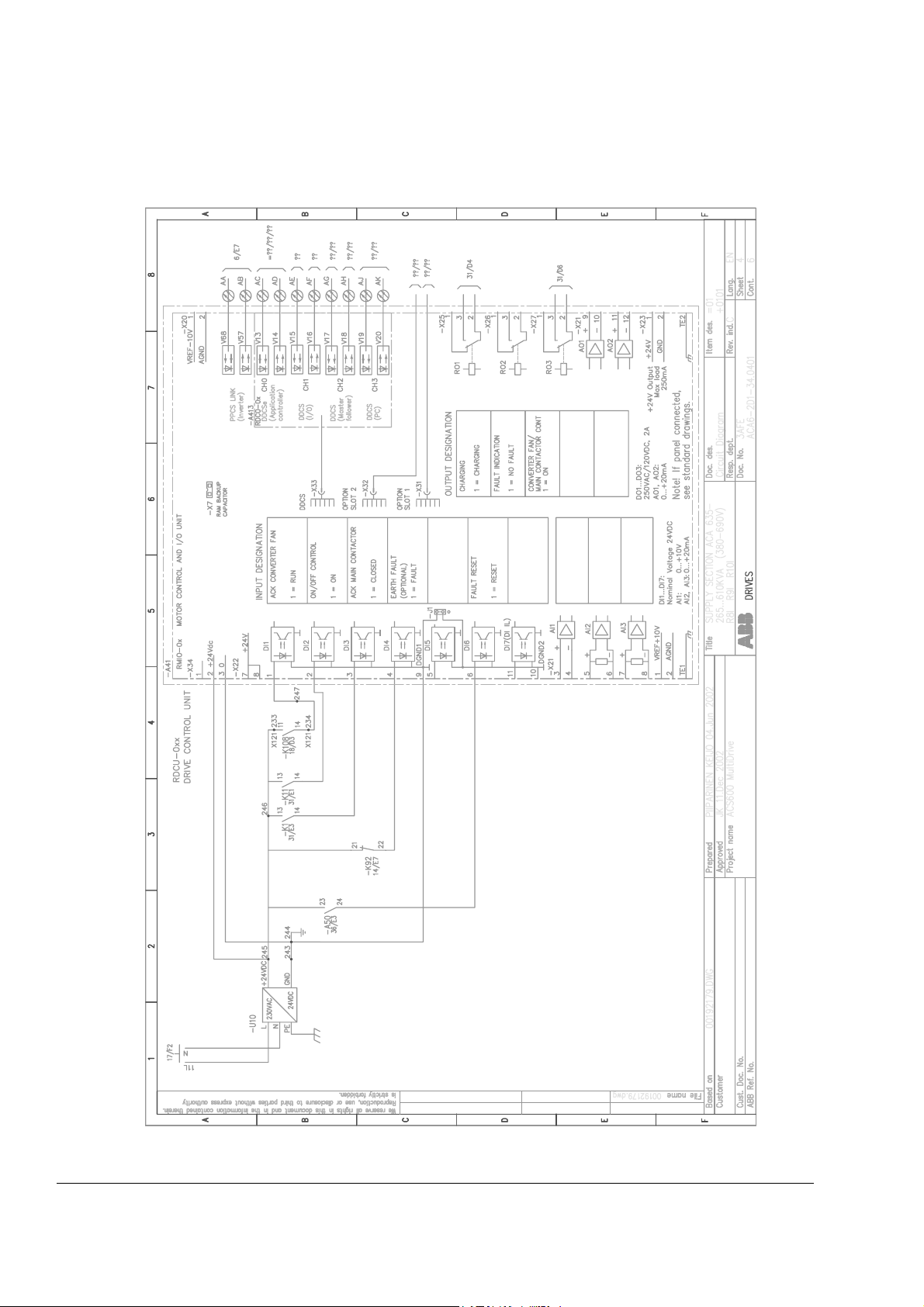
Appendix B Circuit
Diagrams
Page B-4 ADDED: Circuit diagram including the Drive Control Unit
RDCU
12 Update notice
Page 25

Chapter 1 – About this Manual
What this Chapter
Contains
Intended Audience
Parameter Setting
To which Products
this Manual Applies
Contents
This chapter describes the intended audience and contents of this
manual. It contains a table referring to tasks described in other
manuals.
This manual is intended for people who plan the installation,
commission, use and service the drive equipped with an IGBT supply.
Read the manual before working on the drive. You are expected to
know the fundamentals of electricity, wiring, electrical components and
electrical schematic symbols.
The parameters of the IGBT Supply Unit (ISU) Program listed in
this manual need not be set in a normal start-up procedure or in
normal use. However, the ISU parameters can be viewed and
changed using the Control Panel.
This manual applies to the ACA 635 supply sections and ACS 800-17
drives which contain the IGBT Supply Unit.
The control program of the IGBT Supply Unit is described in the
following chapters: Chapter 6 – Firmware Description, Chapter 7 –
Fault Tracing and Chapter 8 – Parameters.
Safety Instructions contain installation and maintenance safety
instructions.
Chapter 2 – Operation Basics describes the operation of the IGBT
Supply Unit.
Chapter 3 – Hardware Description describes the hardware of the
ACA 635 supply sections including descriptions of the LCL filter and
the IGBT supply unit which are parts of the ACS 800-17 as well.
Chapter 4 – Commissioning the Supply Section with ISU describes the
commissioning of a supply section that is equipped with the IGBT
Supply Unit (ISU).
Chapter 5 – Earth Fault Protection describes the earth fault protection
solutions available for a drive equipped with an IGBT supply unit.
Appendix A – Technical Data contains technical data for the ACA 635
giving information on ratings, fuses, cooling requirements, power
losses etc.
ACA 635 IGBT Supply Sections User’s Manual 1-1
Page 26

Chapter 1 – About this Manual
ISU-related
Information in Other
Manuals
Task See
Appendix B – Circuit Diagrams contains some example circuit
diagrams of the ACA 635.
Mechanical and Electrical
Installation of the Drive
Installation of Optional Modules
and DriveWindow
Preventive Maintenance
Technical Data for the
ACS 800-17
Associating ISU with
DriveWindow
ACS 600 MultiDrive Hardware Manual (EN code: 63700118) or ACS800-17 Hardware
Manual (EN code: 64638505)
ACS800-17 Hardware Manual (EN code: 64638505)
DriveWindow Start-up Guide (EN code: 36458585)
When associating DriveWindow 1.3 and 1.4 with the ISU proceed as follows:
System Configuration Messages What to do
Error: Encountered target ‘ISU600-xxxx-x’ is unknown.
Do you wish to associate it?
Associate ‘ISU600-xxxx-x’ With Choose ACS600 MultiDrive
Do you wish association ‘ISU600-xxxx-x’ = ACS600
MultiDrive be permanent?
Click OK.
from the list.
Click Yes.
User Interface Firmware Manual (for System, Standard or Crane Drive Application Program)
The user interface of the IGBT Supply Unit is a CDP 312 Control Panel or a PC, which
is equipped with a DDCS board and DriveWindow.
1-2 ACA 635 IGBT Supply Sections User’s Manual
Page 27
Chapter 2 – Operation Basics
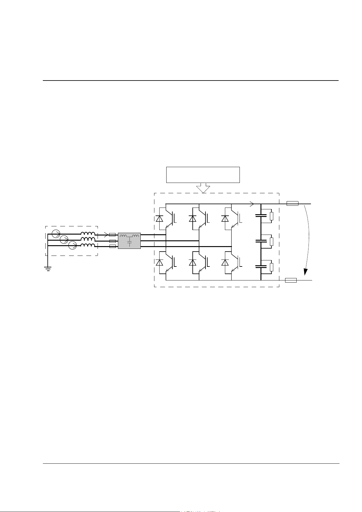
Operation of ISU
Main Circuit Diagram
Supply network
I
U
The ISU is a four-quadrant switching-mode converter, i.e., the power
flow through the converter is reversible. The AC current of the ISU is
sinusoidal at a unity power factor. As a default, the ISU controls the DC
link voltage to the peak value of the line-to-line voltage. The DC voltage
reference can be set also higher by a parameter.
A diagram of the main circuit of the IGBT supply is shown below.
Control and Gate Drivers
Common DC bus
I
dc
LCL Filter
U
c
Control
Converter
The control and modulation is based on the Direct Torque Control
(DTC) method typically used in ACS 600 motor control. Two line
currents and DC link voltage are measured and used for the control.
The control boards are similar to the boards of the inverter.
ACA 635 IGBT Supply Sections, ACS800-17 2-1
Page 28
Chapter 2 – Operation Basics
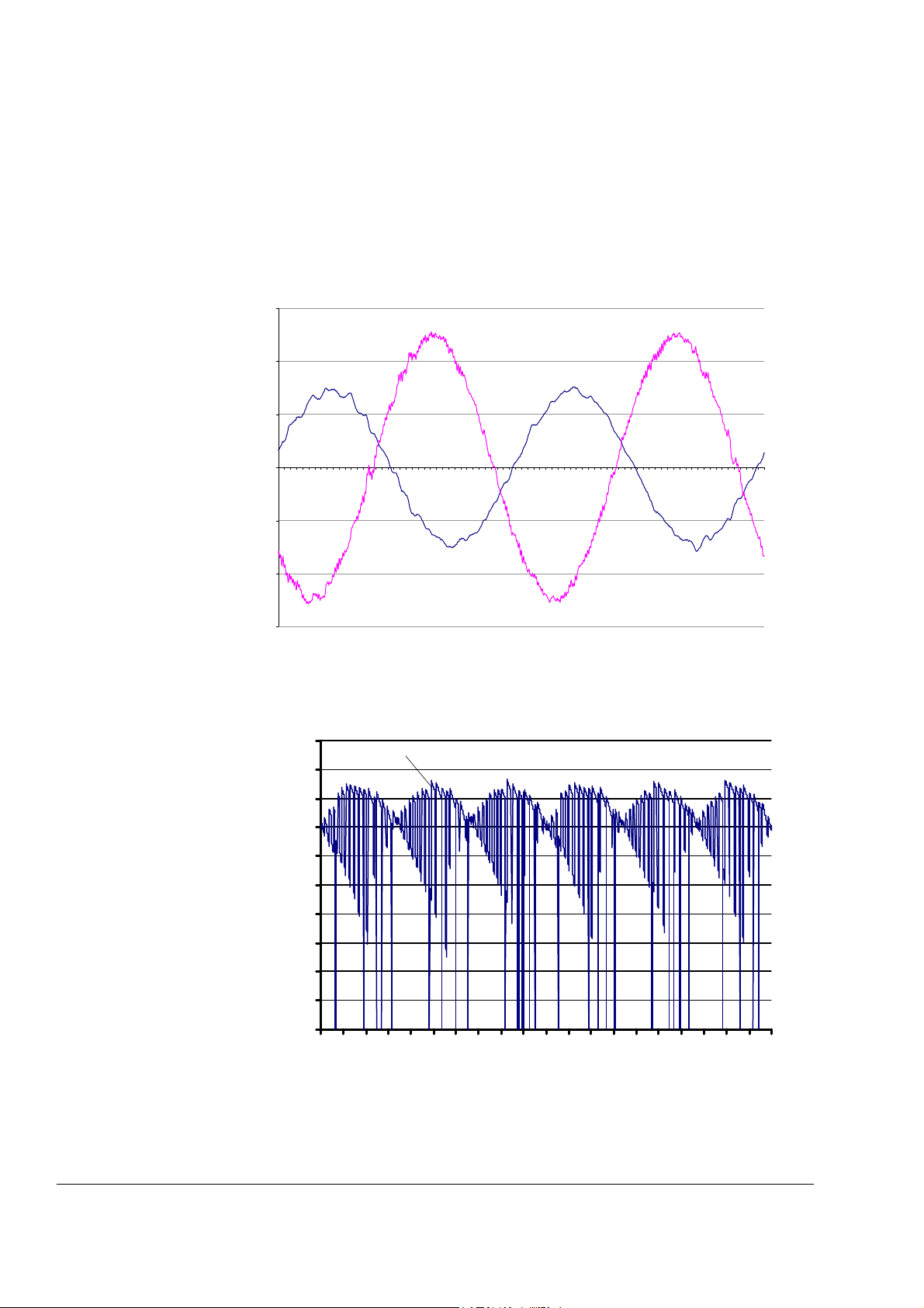
Voltage and Current
Waveforms
The high frequency switching and high du/dt slightly distorts the voltage
waveform at the input of the converter. The depth of the voltage
notches depends on the ratio of network inductance to total line
inductance (network + LCL filter inductance).
Typical line current (i
(A, V)
1200
u
800
i
U
400
0
02468101214161820222426283032343638
-400
-800
) and voltage (uUV) waveforms are shown below.
U
UV
t (ms)
-1200
DC Current A typical DC current (i
(A)
500
450
400
350
300
250
200
150
100
50
0
100 102 104 106 108 110 112 114 116 118
i
dc
) waveform is shown below.
dc
t (ms)
2-2 ACA 635 IGBT Supply Sections, ACS800-17
Page 29

Chapter 2 – Operation Basics
Distortion
Spectrum of the Voltage
DIstortion
IGBT supply unit does not generate characteristic current/voltage
overtones llike a traditional 6- or 12-pulse bridge does, because of the
sinusoidal waveform of the line current. The Total Harmonic Distortion
(THD) in voltage depends slightly on the Short Circuit Ratio in the Point
of Common Coupling (PCC), refer to Appendix A – Technical Data.
A typical spectrum of the voltage distortion at the output of the
transformer is shown below. Each harmonic is presented as a
percentage of the fundamental voltage. n denotes the ordinal number
of the harmonic.
2
1,5
1
0,5
Spectrum of the Line
Current Distortion
0
THD 11 21 31 41 51 61 71 81 91 101 111 121 131 141 151 161 171 181 191
A typical spectrum of the line current distortion is shown below. Each
harmonic is presented as a percentage of the fundamental current. n
denotes the ordinal number of the harmonic.
4
3,5
3
2,5
2
1,5
1
0,5
0
THD 11 21 31 41 51 61 71 81 91 101 111 121 131 141 151 161 171 181 191
ACA 635 IGBT Supply Sections, ACS800-17 2-3
Page 30

Chapter 2 – Operation Basics
2-4 ACA 635 IGBT Supply Sections, ACS800-17
Page 31

Chapter 3 – Hardware Description
Main Components of
a Drive with ISU
Auxiliary
Control
Unit
ACU
NDCU/RDCU
NAMC, NIOC
/ RMIO
ACT PAR FUNC DRIVE
ENTER
LOC
REF
RESET
DIN rail
REM
DIN rail
X2
24 V
~
=
230/115 VAC
The main components of a drive equipped with an IGBT supply unit are
shown below. Two drive sections are drawn in the diagram, in reality
the number of them varies. The control panels are optional. This
chapter describes the supply section.
Supply Section
Incoming
Unit
ICU
Filter Unit and
FIU
charging resistor
with IGBT supply
IGBT
Supply
Unit
Supply
Unit
Braking Sections
Braking Unit
(optional)
Common DC Bus
Chopper
Resistor
Drive Sections
Inverter
ACT PAR FUNC DRIVE
ENTER
LOC
REF
RESET
REM
Inverter
ACT PAR FUNC DRIVE
ENTER
LOC
REF
RESET
REM
AC
Supply Section
The supply section consists of the units listed below:
• Auxiliary Control Unit (ACU)
• Incoming Unit (ICU)
• Filter Unit (FIU)
• IGBT Supply Unit (ISU).
ACA 635 IGBT Supply Sections 3-1
Page 32

Chapter 3 – Hardware Description
Auxiliary Control Unit The following components are located in the Auxiliary Control Unit:
• Drive Control Unit (NDCU), which includes an Application and Motor
Controller (NAMC) Board and a standard I/O (NIOC) Board; or Drive
Control Unit (RDCU), which includes a Motor Controller and
standard I/O Board (RMIO).
• Optical Branching Unit (NPBU) with parallel connected IGBT Supply
Units (frames 2 or 4 times R11i and R12i). NPBU is connected
between NAMC/RMIO and NINT boards (inside the converter
module).
• Control voltage supply (fuses and transformer)
• On/off switch on the cabinet door and relays
• Optional CDP 312 Control Panel and NLMD-01 Monitoring Display
• Optional voltage and current meters
• Control wiring and relays
• Auxiliary voltage filter for sensitive equipment (I
= 17 A, 230/115 V)
N
• Optional emergency and earth fault protection components
• Other options (fieldbus adapter modules, man/machine interfaces
etc.)
Incoming Unit The following components are located in the Incoming Unit:
• Terminals for the input power (AC supply) connection
• Frames R6i to R9i: switch fuse (including AC fuses) and main
contactor. Frames R11i and above: air circuit breaker.
• Optional earthing switch
• Charging fuses and contactor
• Current transformer of optional ammeters
Filter Unit The following components are located in the Filter Unit:
• LCL filter
• Cooling fan for filter
• Charging resistors
• AC fuses (frames R11i and above)
LCL Filters An LCL filter suppresses voltage and current distortion across a wide
frequency range.
3-2 ACA 635 IGBT Supply Sections
Page 33

Chapter 3 – Hardware Description
Short-circuit ratio (Rsc) describes the strength of the supply network.
The diagrams below show the estimated voltage and current distortion
as a function of short-circuit ratio.
The short-circuit ratio can be calculated as shown in chapter Appendix
A – Technical Data / Harmonic Distortion.
Please note that the curves are merely a visualisation of the effect of
the LCL filter and supply network characteristics on the distortion, not a
specification.
Current Distortion (up to 200th) Generated by the Supply Unit at
PCC (Point of Common Coupling)
5
4.5
4
3.5
3
2.5
2
1.5
Current THD [%]
1
0.5
0
0 102030405060708090100
Rsc (Short-circuit Ratio) at PCC
Voltage Distortion (up to 200th) Generated by the Supply Unit at
PCC (Point of Common Coupling)
5
4
3
2
Voltage THD [%]
1
0
0 102030405060708090100
Rsc (Short-circuit Ratio) at PCC
ACA 635 IGBT Supply Sections 3-3
Page 34

Chapter 3 – Hardware Description
IGBT Supply Unit The IGBT Supply Unit includes the parts listed below:
Converter The converter consists of an IGBT bridge which forms controlled dc
• Converter (ACN 634 xxxx)
• Converter cooling fans
• DC fuses
• the following control boards inside the converter:
- Thick-film Hybrid Board (NRED) in 690 V units only for limiting the
maximum voltage
- Power Supply Board (NPOW)
- Main Circuit Interface Board (NINT)
- Control Distribution Board (NXPP) in frame sizes R10i to 4 x R12i
- Gate Driver Power Supply Board (NGPS) in frame sizes R12i and
up for supplying power to NGDR boards
- Gate Driver Board (NGDR)
voltage from the supply network ac voltage. The bridge is capable of
delivering braking energy back to the network.
Frame Size A converter (ACN 634 xxxx) consists of
R6i to R9i one converter module
~
=
R11i to R12i three phase modules (ACN 644 xxxx) = one converter
~
⇒
2 x R11i, 2 x R12i two times three phase modules (ACN 644 xxxx) = two phase
module blocks ⇒ one converter
No. 1
4 x R11i, 4 x R12i four times three phase modules (ACN 644 xxxx) = four phase
module blocks ⇒ one converter
No. 1
~
~
=
=
No. 2
No. 2
=
~
⇒
No. 3
~
~
=
=
~
=
=
⇒
No. 4
3-4 ACA 635 IGBT Supply Sections
Page 35

Chapter 3 – Hardware Description
Main Circuit
Construction
The converter consists of six insulated gate bipolar transistors (IGBT)
with free wheeling diodes and DC capacitors. Frames R8i and R9i are
equipped with parallel connected IGBTs for each phase located on
three power plates. Frame size R11i includes six power plates and
frame size R12i nine power plates.
Configurations
The sections below describe possible configurations of ISU modules.
Basic Configuration The hardware of the IGBT supply unit is similar to the hardware of the
ACS 600 MultiDrive inverter. One NAMC/RMIO board controls the
converter module. It is located inside the Drive Control Unit (NDCU/
RDCU) box. The supply section is equipped with an LCL filter, DC
fuses and AC-fuses/switch fuse OESA. AC fuses are used with a
breaker and a switch fuse is used with a contactor.
ISUICU
OESA
FIU
Converter
Module
AC fuses DC fuses
~
Parallel Connected
Modules
=
Charging circuit
230/115 V
NAMC/
RMIO
NDCU/RDCU
ACU
Parallel connected IGBT supply converter module configuration is
similar to parallel connected inverter module configuration of the
ACS 600 MultiDrive. One NAMC/RMIO board controls all parallel
connected modules. Each module is equipped with an LCL filter and
AC and DC fuses. If one module fails, it can be disconnected by
removing the fuses on both sides of it. The whole supply has a
common disconnecting device. Full redundancy is not possible. The
modules cannot supply the DC link separately, with independent
NAMC/RMIO boards.
ACA 635 IGBT Supply Sections 3-5
Page 36

Chapter 3 – Hardware Description
NDCU/RDCU
NAMC/
RMIO
NPBU
~
=
~
=
~
=
~
=
ICU
Braking Chopper A braking chopper can be connected in parallel with an IGBT supply
unit. The configuration is beneficial when the braking is continuous and
the drive is not allowed to stop if the supply network trips for a short
time.
FIU
ISU
~
=
Braking
Resistor
3-6 ACA 635 IGBT Supply Sections
Braking
Chopper
Page 37

Chapter 4 – Commissioning the Supply Section with ISU
Overview
This chapter describes the commissioning of a supply section that is
equipped with the IGBT Supply Unit (ISU).
WARNING! Only qualified electricians are allowed to commission the
drive. The Safety Instructions on the first pages of this manual must be
followed. Ignoring the safety instructions can cause injury or death.
Installation Checklist
The installation must be checked before commissioning the supply
section. This table refers to the more detailed instruction.
Action Information
Check that the mechanical and electrical installation of the
frequency converter is inspected and OK.
Ensure that the insulation resistance of the assembly is
checked according to instructions given in the Hardware
Manual.
Ensure that the surroundings and inside of the cabinet are
free from dust and loose objects (like cable trimmings and
other waste left from the installation).
See ACS 600 MultiDrive Hardware
Manual (EN code: 63700118) or
ACS800-17 Hardware Manual
(EN code: 64638505). Refer to
Installation Checklist and Insulation
Checks.
After the start, the cooling air fans may
suck nearby loose objects into the unit.
This might cause failure and damage the
unit.
ACA 635 IGBT Supply Sections, ACS800-17 4-1
Page 38

Chapter 4 – Commissioning the Supply Section with ISU
Checks with No
Voltage Connected
This table is a commissioning checklist for the supply section with no
voltage connected.
Action Information
WARNING! Ensure that the disconnector of the supply transformer is locked to open
position, i.e. no voltage is, or can be connected to the drive inadvertently. Check also by
measuring that there actually is no voltage connected.
1. Air Circuit Breaker, Relays, Switches
If the supply section is equipped with an air circuit breaker,
check the current trip levels of the air circuit breaker.
Check the settings of the relays for the emergency stop
circuit.
Check the settings of the time relays.
Check the settings of other relays.
Check the settings of the breakers/switches of the auxiliary
circuits.
The trip levels have been preset at the
factory. In most applications there is no
need to change these settings.
See the circuit diagrams delivered with
the device.
See the circuit diagrams delivered with
the device.
See the circuit diagrams delivered with
the device.
See the circuit diagrams delivered with
the device.
Check that all breakers/switches of the auxiliary circuits are
open.
2. Supply Tripping Circuit
Check the operation of the supply transformer tripping
option.
3. Auxiliary Control Voltage Transformer
Check the wirings to the primary and secondary side
terminals of the auxiliary control voltage transformer.
This is an optional feature. See the
circuit diagrams delivered with the
device.
See the circuit diagrams delivered with
the device for the correspondence
between the wirings and the voltage
levels.
4-2 ACA 635 IGBT Supply Sections, ACS800-17
Page 39

Chapter 4 – Commissioning the Supply Section with ISU
Connecting Voltage to
Auxiliary Circuits
WARNING! When voltage is connected to the input terminals of the supply section,
the voltage will also be connected to the auxiliary control unit and to auxiliary circuits
- also to the ones wired to drive sections.
Make sure that it is safe to connect voltage to the input terminals. Ensure that while
the voltage is connected:
• Nobody is working with the unit or circuits that are wired from outside into the
cabinets.
• The cabinet doors are closed.
Disconnect the 230 VAC cables that lead from the terminal
blocks to the outside of the equipment and have not yet
been checked, and the connections which may not yet have
been completed.
Make sure that the main contactor/air circuit breaker cannot
inadvertently be closed by remote control, e.g. by
temporarily opening some connection in its control circuit.
This table describes how to connect voltage to the supply section input
terminals and to the Auxiliary Control Unit (ACU) for the first time.
Action Information
Be ready to trip the main breaker of the supply transformer
in case anything abnormal occurs.
Ensure that all cabinet doors are closed.
Close the main breaker of the supply transformer.
Close the main disconnecting switch of the supply section.
Close the main disconnecting switch of the auxiliary circuit.
ACA 635 IGBT Supply Sections, ACS800-17 4-3
Page 40

Chapter 4 – Commissioning the Supply Section with ISU
Checks with Voltage
Connected to
Auxiliary Circuits
This table is a commissioning checklist for the supply section with
voltage connected to the input terminals, and Auxiliary Control Unit
(ACU).
Action Information
WARNING! This section includes instructions for checking/measuring circuits under
voltage. Only a qualified person is allowed to do the work. An appropriate and
approved measuring instrument must be used.
IF IN DOUBT, DO NOT PROCEED!
Ensure the actions described in section Connecting Voltage
to Auxiliary Circuits are completed.
Measure phase voltages by using the switch and meter on
the cabinet door.
Check the secondary side voltage of the auxiliary voltage
transformer. Close the protection switch on the secondary
side.
Close the breakers of the auxiliary circuits one by one.
Check each circuit by
• measuring for correct voltage at terminal blocks
This is an optional feature. If included,
see the circuit diagrams delivered with
the device.
See the circuit diagrams delivered with
the device.
Note: The cooling fans of the IGBT
supply unit will start after the main
contactor is closed.
• checking the operation of the devices connected to the
circuit.
Check the connection from all external auxiliary voltage
sources (e.g. from an Uninterrupted Power Supply, UPS) to
the auxiliary control unit.
This is an optional feature. If included,
see the circuit diagrams delivered with
the device.
4-4 ACA 635 IGBT Supply Sections, ACS800-17
Page 41

Chapter 4 – Commissioning the Supply Section with ISU
Connecting Voltage to
IGBT Supply Unit
This table describes how to connect voltage to the IGBT supply unit
and the DC busbars for the first time.
Action Information
WARNING! When connecting voltage to the IGBT supply unit, the DC busbars will
become live, as will all the inverters connected to the DC busbars.
Make sure that it is safe to connect voltage to the IGBT supply unit. Ensure that:
• Nobody is working with the unit or circuits that are wired from outside into the
cabinets.
• All cabinet doors are closed.
1. First Voltage Switch-on for the IGBT Supply Unit
If the supply section is equipped with an air circuit breaker,
set the air circuit breaker current settings to 50% of the onload values.
Ensure that all cabinet doors are closed.
Be ready to trip the main breaker of the supply transformer if
anything abnormal occurs.
It is recommended to set relatively low
current values at the first voltage switchon.
Close the main disconnecting switch of the supply section.
Close the main contactor / air circuit breaker of the supply
section.
2. Air Circuit Breaker Current Settings
Increase the air circuit breaker current settings to the onload values.
ACA 635 IGBT Supply Sections, ACS800-17 4-5
Page 42

Chapter 4 – Commissioning the Supply Section with ISU
Starting
This procedure instructs how to start the IGBT supply unit.
Action Information
WARNING! When starting the IGBT supply unit, the DC busbars will become live, as
will all the inverters connected to the DC busbars.
Make sure that it is safe to start the IGBT supply unit. Ensure that:
• Nobody is working with the unit or circuits that are wired from outside into the
cabinets.
• All cabinet doors are closed.
• The covers of the motor terminal boxes are on.
Ensure the actions described in subsections Checks with No
Voltage Connected and Checks with Voltage Connected to
Auxiliary Circuits are completed.
Be ready to trip the main breaker of the supply transformer if
anything abnormal occurs.
Close the main disconnecting switch of the auxiliary circuit.
Close the main disconnecting switch of the supply section.
Start the ISU:
• reset the starting logic by the RESET button on the cabinet
door
• turn the starting switch on the cabinet door from position 0
to 1 and
• turn the starting switch to the START position and release
it.
4-6 ACA 635 IGBT Supply Sections, ACS800-17
Page 43
Chapter 4 – Commissioning the Supply Section with ISU
Checks with ISU
Supply Started
This table is a list of checks to be done after the IGBT supply unit is
started and the DC busbars are live.
Action Information
WARNING! This section includes instructions for checking/measuring circuits under
voltage. Only a qualified person is allowed to do the work. An appropriate and
approved measuring instrument must be used.
IF IN DOUBT, DO NOT PROCEED!
1. Basic Checks
Check that the cooling fan in the supply section rotates
freely in the right direction, and the air flows upwards.
FLOATING NETWORK (IT NETWORK)
1. Earth Fault Protection Based on an Insulation Monitoring Device
Check the setting of Parameter 30.04 EXT EARTH FAULT,
and the connection to DI4.
Check the tuning of the insulation monitoring device for the
earth fault protection (Bender).
The insulation monitoring device is tuned at the factory. If
further tuning is required, see the IRDH265 Operating
Manual by Bender (code: TGH1249).
A paper sheet set on the lower gratings
stays. Fan runs noiselessly.
This is an optional feature (IRDH265-x).
If included, see the circuit diagrams
delivered with the device. For
information on the protection principle,
see Chapter 5 – Earth Fault Protection
and the IRDH265 Operating Manual by
Bender (code: TGH1249).
SYSTEM EARTHED NETWORK (TN NETWORK)
1. Earth Fault Protection Based on Internal Current Measurement
Check the setting of Parameter 30.02 EARTH FAULT.
Parameters
The parameters of the ISU need not be set in a normal start-up
procedure or in normal use.
This is a programmable feature. For
information on the protection principle,
see Chapter 5 – Earth Fault Protection.
ACA 635 IGBT Supply Sections, ACS800-17 4-7
Page 44
Chapter 4 – Commissioning the Supply Section with ISU
Controlling the ISU
with an Overriding
System
This procedure instructs how to control or monitor the IGBT supply unit
from an overriding system by using data sets 1 and 2 or 10 to 33 with
DDCS and DriveBus communication protocols.
The communication works via fibre optic cables connected to channels
CH0 to CH3 on the NAMC board. When the RMIO board is used,
channels CH0 to CH3 are provided by the DDCS communication
option module (RDCO) which is inserted into the optional module slot
marked “DDCS” on the RMIO board.
Action Parameter
Set this parameter to MCW if the ISU will be controlled with
an overriding system. Set to I/O if the ISU is only monitored.
Set this parameter to FBA DSET1 or FBDSET 10 depending
on what datasets the overriding system uses.
Connect the fibre optic cables to channel CH0.
Set the node address and communication mode for channel
CH0 as follows:
Controller Node Address Par. 71.01 CH0
DDCS DriveBus Module-
Bus
APC2 1 - - NO
AC70 - - 17...125 NO
AC80 - 1...12 17...125 YES
FCI (CI810A) - - 17...125 NO
DRIVEBUS MODE
98.01 COMMAND SEL
98.02 COMM MODULE
70.01 CH0 NODE ADDR
71.01 CH0 DRIVEBUS MODE
Note: Setting of Par. 71.01 is valid after
the next power-up.
Check that the communication is working.
Set the delay time for a communication fault indication. 70.04 CH0 TIMEOUT
Select the action upon a communication fault on channel
70.05 CH0 COMM LOSS CTRL
CH0.
Select RING, if channels CH0 are connected in a ring. The
70.19 DDCS CH0 HW CONN
default setting STAR is typically used with DDCS branching
units NDBU-85/95.
If a PC is used for control/monitoring, set the node address
70.15 CH3 NODE ADDR
for channel CH3. Addresses 1...75 and 126...254 are
allowable. The rest of the addresses are reserved for
branching units NDBU-85/95 (see NDBU-85/95 User’s
Manual, code: 64285513).
Note: If the channels CH3 of several supply units have been connected in
a ring or in a star (via a branching unit), give each converter a unique
node address. The new address becomes valid only on the next NAMC
board power-on.
4-8 ACA 635 IGBT Supply Sections, ACS800-17
Page 45

Chapter 4 – Commissioning the Supply Section with ISU
Action Parameter
Select RING, if channels CH3 have been connected in a
ring. The default setting STAR is typically used with DDCS
branching units NDBU-85/95.
Select the addresses for the data to be received from the
overriding system and for the data to be transmitted to the
overriding system. Note the different updating intervals.
Test the functions with received and transmitted data.
Fieldbus Adapters
Action Parameter
Set the communication with these parametes. See the
appropriate fieldbus adapter manual.
On-load Checks
This table is a commissioning checklist for the loaded supply section.
Action Information
70.20 CH3 HW CONNECTION
Groups 90 and 91 DATASET
RECEIVE ADDRESSES
Groups 92 and 93 DATASET
TRANSMIT ADDRESSES
Group 51 COMMUNICATION
MODULE
Check the correct operation of the current meters.
Check the correct operation of the emergency-stop circuits.
This is an optional feature. See the
circuit diagrams delivered with the
device.
This is an optional feature. See the
circuit diagrams delivered with the
device.
ACA 635 IGBT Supply Sections, ACS800-17 4-9
Page 46

Chapter 4 – Commissioning the Supply Section with ISU
4-10 ACA 635 IGBT Supply Sections, ACS800-17
Page 47

Chapter 5 – Earth Fault Protection
Overview
Floating Network
Insulation Monitoring
Diagram This diagram shows earth fault protection implemented with an
Device
This chapter contains descriptions of the earth fault protection solutions
available for a drive equipped with an IGBT supply unit. The settings
required at the start-up are given in Chapter 4 – Commissioning the
Supply Section with ISU.
This section describes the earth fault protection principle in a floating
network.
insulation monitoring device.
L1 L2 L3
Transformer Supply Unit
~
DC Busbar
Inverter Units
=
BENDER
Insulation
Monitoring
Device
=
=
~
M
3~
IL > 0, Leakage Current
~
M
3~
Description The monitoring device is connected between the unearthed system
and the equipotential bonding conductor (PE).
A pulsating AC measuring voltage is superimposed on the system
(measuring principle Adaptive Measuring Pulse, AMP is developed by
BENDER, patent pending). The measuring pulse consists of positive
and negative pulses of the same amplitude. The period depends on the
respective leakage capacitances and the insulation resistance of the
system to be monitored.
The setting of the response values and other parameters can be
carried out via the function keys. The parameters are indicated on the
display and they are stored in a non-volatile memory after setting.
ACA 635 IGBT Supply Sections 5-1
Page 48

Chapter 5 – Earth Fault Protection
With Bender’s insulation monitoring device it is possible to set up two
response values: ALARM1 and ALARM2. Both values have an own
alarm LED, which illuminates if reading is below these selected
response values.
In Case of an Earth Fault An earth fault closes the measuring circuit. An electronic evaluation
circuit calculates the insulation resistance which is indicated on an LC
display or an external ohmmeter after the response time.
The alarm actions depend on the electric connection: for example
ALARM1 can be wired to give a warning, and ALARM2 can be wired to
trip the device.
Further Information Further information about the insulation monitoring device is available
in IRDH265 Operating Manual (code TGH1249) published by the
manufacturer, BENDER companies.
System-earthed
Network
Diagram This diagram shows earth fault protection implemented with internal
Description The line current unbalance is calculated from measured currents I
In a system-earthed network, the neutral point of the supply
transformer is earthed solidly. This section describes an internal earth
fault protection principle in a system-earthed network.
current transducers in the ACA 635.
L1 L2 L3
Transformer
IGBT Supply Unit
~
Inverter Units
DC Busbar
=
and I
=
IL > 0, Leakage Current
.
w
~
M
3~
=
~
M
3~
, IV
U
In Case of an Earth Fault In normal operation the current sum is zero. An earth fault leads to an
unbalance in the 3-phase system and therefore to a current sum
different from zero. If the current unbalance exceeds the limit set in
Par. 30.03 EARTH FAULT LEVEL, an alarm is given or the device is
tripped.
5-2 ACA 635 IGBT Supply Sections
Page 49

Chapter 6 – Firmware Description
Overview
Control Principle
This chapter describes the IGBT supply unit control program. Note:
The parameters listed in this chapter need not be set in normal
use. They are mentioned for explaining the control principle only.
The following symbols are used:
1.10
113.05
, 11.11
Actual signal or parameter (see Chapter 8 – Parameters).
Parameter above 100. These parameters are not visible to
the user unless the passcode is entered for the Parameter
Lock in Parameter 16.03 PASS CODE. These parameters
are not allowed to be changed without ABB’s permission.
The fundamental theory of line converter operation can be represented
by an equivalent circuit with an AC choke and vector diagrams (below),
where
____ motoring
_ _ _ generating
U
network voltage vector
1
U
line converter voltage vector
2
AC choke voltage vector
U
L
ψ
“network flux” vector
1
ψ
“line converter flux” vector
2
“AC choke flux” vector
ψ
L
δ power transfer angle.
U
2gen
jωL
U
1
I
U
2
jωLi = U
U
1
I
δ
I
gen
ACA 635 IGBT Supply Unit Program 6-1
L
U
2
ψ
1
ψ
L
ψ
2
Page 50

Chapter 6 – Firmware Description
The primary function of the ISU is to control the power transfer
between the network and the DC link. The purpose of the AC choke
(represented by reactance X = jωL) is to smooth the line current and to
act as an energy storage for the switch-mode supply. Power transfer
equation between the network and the ISU is presented below:
UU
P =
21
δ
sin
X
Real power is being transferred only if an angle difference exists
between the two voltage vectors. Reactive power transfer equation is
presented below:
Q −=
U
2
1
X
UU
21
δ
cos
X
For the desirable magnitude and the direction of the power and
reactive power flow, the length of the converter voltage vector and its
phase angle δ (with respect to the line voltage vector) must be
controlled. The DC voltage is controlled by keeping the power (energy)
equilibrium between the line and the drives in the DC link constant. The
sign of the angle determines the direction of the power flow.
The output AC voltage is controlled by setting the length of the flux
reference to correspond to the desired output voltage level producing
cosfii = 1.0.
The ISU control needs measurements of the DC link voltage and two
line currents. The “stator flux” (integral of the voltage vector of the ISU)
is calculated by integrating the voltage vector used to generate the
output voltage of the ISU. This is due to the fact that the existing
voltage in the network can be thought to be generated by a rotating
magnetic flux encircled by coils. Each of these coils is one of the line
voltage phases. The voltage in the coils can be expressed by the
formula below:
ψ
d
=
U
dt
The virtual torque generated by the ISU is calculated as a cross
product of flux and current vectors:
IxTψ=
Power can also be expressed as a product of torque and angular
velocity:
P ωT=
6-2 ACA 635 IGBT Supply Unit Program
Page 51

Chapter 6 – Firmware Description
If the network frequency is constant, power is directly proportional to
the torque. By controlling torque, power transferred between the ISU
and the network can be set to a value that keeps the DC link voltage
constant. These basic facts enable the use of the DTC method which
relies on control of flux and torque.
The main difference between DTC and conventional PWM is that the
torque is controlled at the same time level as power switches (25 ms).
There is no separate voltage and frequency controlled PWM
modulator. All selections of the switches are based on the
electromagnetic state of the ISU. This kind of control method can be
realised only by using a high speed signal processing technology. The
digital signal processor Motorola 56xxx is used in the ACS 600 product
family to achieve sufficient speed.
Identification Routine
The ISU adapts itself to the supply network and no data concerning the
network conditions is to be set. The converter rating plate data is
downloaded in the software package.
When the ISU is connected to the network for the first time, an
identification routine must be completed. The identification routine is
executed each time after the NAMC/RMIO board is powered and the
line-side converter is started provided that Parameter 99.08 AUTO
LINE ID RUN is set to YES.
The identification routine can be executed manually also after the next
start (without power up of the NAMC/RMIO board) by setting the
Parameter 99.07 LINE SIDE ID RUN to YES and pressing the Control
Panel Start key. This can be done if there is doubt that the automatic
identification routine has failed, or an automatic routine is not desirable
as it takes approximately 5 seconds and requires that the line-side
converter is not loaded.
During ID Run voltage level in the supply network is estimated based
on DC voltage measurement. The value is indicated by Parameter 2.07
DC REF INITIALIZ. If If the value of Parameter 2.07 DC REF
INITIALIZ is within allowed limits (see Par. 9.11 bit 9 NET VOLTAGE
fault), the procedure goes on further to define the frequency of the
network (50 Hz or 60 Hz) and the phase order.
ACA 635 IGBT Supply Unit Program 6-3
Page 52

Chapter 6 – Firmware Description
The parameters concerning the identification routine are presented
below.
Code Parameter Unit Description
99.07 LINE SIDE ID RUN Manual identification run
99.08 AUTO LINE ID RUN Automatic identification run after power up
of the NAMC/RMIO board and next start
2.07 DC REF INITIALIZ V Nominal DC reference
Fault
9.11 bit 9 NET VOLT FLT Supply voltage is not valid
Charging
Synchronization
When the control has received a start command, the charging
contactor is closed. When the DC link voltage is high enough, the main
contactor/breaker is closed and the charging contactor is opened. This
procedure is controlled by the NAMC board via NIOC board digital
outputs RO1 and RO3 (or by the RMIO board via digital outputs RO1
and RO3).
If the charging is not completed, i.e. the DC link voltage has not
exceeded the value of Parameter 30.12 DC UNDERVOLT TRIP or the
charging current is not below 5% of I
10s/60s
, a fault bit is set (Parameter
9.11 SUPPLY FAULT WORD bit 0 CHARGING FLT).
The ISU is synchronized to the network by three-phase short-circuits.
On the basis of the short-circuit current, the ISU can identify the phase
order of the supply network and the starting point for the flux/voltage
vector. The phase order of the supply can be changed without
performing the identification routine again.
The synchronization can also be done without phase order check by
setting Parameter 99.06 FAST SYNC to YES.
If a synchronization trial fails, the ISU makes up to 9 additional trials if
the supply has not been disconnected. One reason for a failed
synchronization is too low a short-circuit current due to the high
impedance of the network.
The synchronization parameters are listed below.
Code Parameter Unit Description
99.06 FAST SYNC One short-circuit pulse is used.
Fault
9.02 SUPPLY PHASE Synchronization failed, phase(s) missing.
9.11 SYNCHRO FLT Synchronization failed, short-circuit current
below limit.
6-4 ACA 635 IGBT Supply Unit Program
Page 53

Chapter 6 – Firmware Description
Starting Sequence
MAIN CTRL WORD
MAIN CTRL WORD
7.01
7.01
During the charging procedure the main contactor is closed, and after
the synchronization routine is completed, the modulator is started and
the ISU runs normally.
A simplified block diagram of the modulator starting (from starting
switch on the cabinet door or via fieldbus) is presented below. For
description of the starting procedure, see the next pages.
MCW = (0)
I/O = (1)
(0)
(1)
(0)
(1)
(0)
(1)
SWITCH
&
> 1
MAIN STATUS WORD
8.01
bit 8
bit 0
DI2
bit 3
COMMAND SEL
98.01
&
ACA 635 IGBT Supply Unit Program 6-5
Page 54

Chapter 6 – Firmware Description
Start by the Starting
Switch
On/off switch
On/off from relay via
1.
digital input DI2
2.
Charging contactor
3.
Main contactor
Synchronization
4, 5, 6
Modulating
7.
By default, the ISU control commands (ON/OFF) are given by the
starting switch on the cabinet door which is wired to digital input DI2.
The starting sequence is as follows:
2.5 s
0.5 s
Step Function
1. ISU control receives the ON command (DI2 rising edge) from the starting
switch.
2. ISU control logic closes the charging contactor control circuit (RO1).
3. ISU control logic closes the main contactor and cooling fan control circuit
(RO3).
4. ISU control logic receives the “main contactor on” acknowledgement (DI3).
5. ISU control logic receives the “cooling air fan in operation” acknowledgement
(DI1).
6. ISU synchronizes itself to the supply network in case DC voltage is OK
(charging is completed successfully).
7. ISU control starts modulation and opens the charging contactor control circuit
(RO1). The inverter units can be started.
6-6 ACA 635 IGBT Supply Unit Program
Page 55

Chapter 6 – Firmware Description
Start via Fieldbus To enable the fieldbus control Parameter 98.01 COMMAND SEL must
be set to MCW. The DC bus can be charged and the modulator started
separately via fieldbus. The DC bus can be charged in two ways:
1. by rising edge of Parameter 7.01 MAIN CTRL WORD bit 0 and
simultaneous high level of digital input DI2 (starting switch on the
cabinet door in position 1).
High level of digital
input DI2
Parameter 7.01 MAIN
CTRL WORD bit 0
(starts charging)
Charging contactor
Main contactor
Parameter 7.01 MAIN
CTRL WORD bit 0 = 1
Digital input DI2
(starts charging)
Charging contactor
Main contactor
2.5 s
0.5 s
2. by rising edge of digital input DI2 (from starting switch) and
simultaneous high level of Parameter 7.01 MAIN CTRL WORD
bit 0.
2.5 s
0.5 s
The modulator is started by high level of Parameter 7.01 MAIN CTRL
WORD bit 3, and stopped by low level of bit 3. The modulator can be
started only after the charging of the DC bus is completed.
Parameter 7.01
MAIN CTRL WORD
bit 3
Synchronization
Modulation
ACA 635 IGBT Supply Unit Program 6-7
Page 56
Chapter 6 – Firmware Description
Stop
Missing Phase
A stop signal from the on/off switch on the cabinet door disables the
modulator and opens the main contactor. The modulator can be
stopped also from the key on the Control Panel and from
DriveWindow in local mode, and from an overriding system in remote
mode. These functions do not open the main contactor.
When the modulator is stopped in local mode or by an overriding
system, the ISU moves to 6-pulse diode bridge mode.
There is no direct AC voltage measurement in the ISU. The lost supply
voltage is identified with current and DC voltage measurement.
When the ISU detects that the current has been below 0.64 percent of
I
10s/60s
for 1.5 milliseconds, an alarm (Parameter 9.12 SUPPLY
ALARM WORD bit 10 NET LOST) is generated. The ISU tries to
resynchronize as long as the DC voltage is greater than the value of
Parameter 30.12 DC UNDERVOLT TRIP. The resynchronizing checks
are made at 20 ms intervals. If the voltage in the DC link falls below the
limit defined by Par. 30.12 DC UNDERVOLT TRIP, the ISU will open
the main contactor/breaker and a fault (Parameter 9.11 bit 14 DC
UNDERVOLT) is generated.
Code Parameters Unit Description
30.12 DC UNDERVOLT TRIP V Undervoltage tripping limit
Alarm
9.12 bit 10 NET LOST Supply lost alarm
Fault
9.11 bit 14 DC UNDERVOLT Undervoltage tripping
6-8 ACA 635 IGBT Supply Unit Program
Page 57

Chapter 6 – Firmware Description
Control Diagram
Hysteresis
Torque ref.
Flux ref.
A block diagram of the measurements and principle of the ISU control
program is shown below. S1, S2 and S3 denote the power switches.
Direct torque and flux
hysteresis control
Actual
flux
Actual value
calculation
Reactive power
control
DC voltage
control
Switching
frequency control
Actual
torque
Torque bits
Flux bits
Control bits
ASICs
Optimal
switching
logic
DC voltage
S1, S2, S3
Current
S1, S1, S3
Supply network
Controllers
Reactive power reference
Switching frequency reference
DC voltage reference
The control includes two main controllers:
• torque and flux hysteresis control
• dc voltage controller.
On the basis of measurements the following items are calculated:
• actual value for flux
• actual value for torque
• actual value for reactive power
• estimate for frequency.
ACA 635 IGBT Supply Unit Program 6-9
Page 58

Chapter 6 – Firmware Description
DC Voltage Controller The ISU control has two reference values for the DC voltage control:
• Parameter 23.01 DC VOLT REF (user given reference)
• Parameter 2.05 DC REF Q-CTRL (minimum DC voltage reference
calculated by reactive power controller).
DC REF Q-CTRL
2.05
DC VOLT REF
23.01
RAMPING
120.01 DC RAMP UP
120.02 DC RAMP DOWN
SELECTOR
A
MAX(A,B)
B
LIMITER
113.01 DC REF MAX
113.02 DC REF MIN
In normal mode, the ramped value of Parameter 23.01 DC VOLT REF
is selected if it is higher than Parameter 2.05 DC REF Q-CTRL. The
DC reference ramping times are set by Parameters 120.01 DC UP
TIME and 120.02 DC DOWN TIME. Minimum and maximum values for
the DC reference are set by Parameters 113.01 DC REF MAX and
113.02 DC REF MIN.
Reference List The references are listed below.
Code Parameter Unit Description
23.01 DC VOLT REF V User given reference
113.01 DC REF MAX V Upper limit for the reference = 1.2
113.02 DC REF MIN V Lower limit for the reference = 0.65
120.01 DC RAMP UP s DC voltage reference ramp time from 0
120.02 DC RAMP DOWN s DC voltage reference ramp time from
Actual Value
1.10 160.04 DC VOLTAGE V Actual DC voltage
2.05 DC REF Q-CTRL V Reference from reactive power control
2.06 DC REF RAMP V Ramped and limited reference
DC REF RAMP
2.06
DC VOLTAGE
1.10
+
-
sqrt(2) · Par. 4.04 CONV NOM
VOLTAGE
sqrt(2) · Par. 4.04 CONV NOM
VOLTAG
to sqrt(2)
· Par. 4.04 CONV NOM
VOLTAGE. Default 1 s.
· Par. 4.04 CONV NOM
sqrt(2)
VOLTAGE to 0. Default 1 s.
PI
Torque ref.
for
hysteresis
control
·
·
The DC voltage controller is the primary controller for the ISU.
The DC voltage controller keeps the DC voltage in a preset reference
in all load conditions. An error signal is calculated from DC voltage
measurement (Actual Signal 1.10 DC VOLTAGE) and Actual Signal
2.06 DC REF RAMP. The output of the DC voltage PI controller is the
torque reference for hysteresis control.
6-10 ACA 635 IGBT Supply Unit Program
Page 59

Chapter 6 – Firmware Description
The PI controller parameters are pretuned. There is no need to retune
them.
Reactive Power Control The reactive power control sets the flux reference for hysteresis control
to values with which zero reactive power is achieved.
Reactive power control is capable of generating a preset amount of
reactive power (Parameter 24.01 Q POWER REF) to the network
(positive = capacitive, negative = reactive) by changing the flux length.
Increasing the ISU flux length higher than the network flux length,
capacitive power is generated to the network and vice versa. Increased
flux means that the output voltage of the ISU is higher than the network
voltage.
Reactive power control parameters are listed below.
Code Parameter Unit Description
24.01 Q POWER REF % Reactive power in percentage of the
nominal power
1.07 REACTIVE POWER kVAr Calculated reactive power
120.03 QPOW RAMP UP s Reactive power reference ramp up time
from 0 kVAr to the absolute value of Par.
4.06 CONV NOM POWER. Default 1 s.
120.04 QPOW RAMP DOWN s Reactive power reference ramp down
time from the absolute value of Par. 4.06
CONV NOM POWER to 0 kVAr. Default
1s.
A block diagram of reactive power control is shown below.
Q POWER REF
24.01
RAMPING
+
PI Flux ref. for hysteresis control
-
120.03 QPOW RAMP UP
120.04 QPOW RAMP DOWN
1.07
REACTIVE POWER
ACA 635 IGBT Supply Unit Program 6-11
Page 60

Chapter 6 – Firmware Description
6-12 ACA 635 IGBT Supply Unit Program
Page 61

Chapter 7 – Fault Tracing
Overview
This chapter explains the fault tracing procedure based on the warning
and fault messages given by the ISU program. A factory installed
control panel in the line-side converter is required in this procedure. For
control panel use and motor-side inverter fault tracing, see the
Firmware Manual of the application program.
All warning and fault messages are presented in tables below with
information on the cause and remedy for each case. Most warning and
fault conditions can be identified and cured with that information. If not,
contact an ABB service representative.
CAUTION! Do not attempt any measurement, parts replacement or
other service procedure not described in this manual. Such action will
void guarantee, endanger correct operation, and increase downtime
and expense.
WARNING! All electrical installation and maintenance work described
in this chapter should only be undertaken by a qualified electrician. The
Safety Instructions on the first pages of this manual must be followed.
Fault Tracing
Fault Resetting An active fault can be reset either by pressing the keypad RESET key,
The drive is equipped with advanced protection features that
continuously guard the unit against damage and down time due to
incorrect operating conditions and electrical and mechanical
malfunctions.
The warning message disappears when any of the Control Panel keys
is pressed. The warning will reappear in one minute if conditions
remain unchanged. If the drive is operated with the Control Panel
detached, the red LED in the Control Panel mounting platform indicates
fault condition.
For setting of programmable warning and fault messages and
functions, refer to Chapter 8 – Parameters.
by digital input or fieldbus, or switching the supply voltage off for a
while. When the fault has been removed, the drive can be started.
ACA 635 IGBT Supply Sections, ACS800-17 7-1
Page 62

Chapter 7 – Fault Tracing
Fault History When a fault is detected, it is stored in the Fault History. The last faults
and warnings are stored with the time the fault was detected.
WARNING! After a fault reset, the drive will start if the start signal is on.
Before the reset, switch off the external start signal or ensure that it is
safe to start.
The Fault History can be viewed by pressing or in the Actual
Signal Display Mode. The Fault History can then be scrolled with
and . To exit the Fault History press or . The Fault History
can be cleared by pressing the RESET key.
Fault and Warning
The tables below show the warning and fault messages.
Messages
Warning Messages
Warning Cause What to do
ACS 600 TEMP/
ACS 800 TEMP
Par. 9.12 bit 4
AI<MIN FUNC
Par. 9.12 bit 3
CH0 COM LOST
Par. 9.12 bit 0
CURRENT LIM
Par. 9.12 bit 5
DI5 = 0
Par. 9.12 bit 14
Excessive IGBT module temperature.
A warning is given if the temperature exceeds
115 °C.
I/O reference 4...20 mA is below 3.1 mA when
Par. 13.06 MINIMUM AI2 or Par. 13.10
MINIMUM AI3 is set to 4 mA.
Communication break detected on CH0
receive.
(can be deactivated: see Parameter 70.04)
Current limit is exceeded. The limit is 220% of
I
1base(10s/60s)
Digital input DI5 is OFF (0). Check the function indicated via digital input
.
Check ambient conditions.
Check air flow and fan operation.
Check heatsink fins for dust pick-up.
Check line current against unit current.
Check for proper analogue control signal level.
Check the control wiring.
Check the fibre optic cables between the
NAMC board / RDCO module and overriding
system (or fieldbus adapter). Test with new
fibre optic cables.
Check that the CH0 node address (Par. 70.01
CH0 NODE ADDR) is correct in the ISU.
Check the status of the fieldbus adapter. See
appropriate fieldbus adapter manual.
Check parameter settings of Group 51, if a
fieldbus adapter is present. Check the
connections between the fieldbus and the
adapter.
Check that the bus master is communicating
and correctly configured.
Limit inverter actual power or lower the
reactive power percentage in Par. 24.01 Q
POWER REF.
DI5.
7-2 ACA 635 IGBT Supply Sections, ACS800-17
Page 63

Warning Messages
Warning Cause What to do
E EARTH FLT
Par. 9.12 bit 13
EARTH FAULT
Par. 9.12 bit 13
NET LOST
Par. 9.12 bit 10
PANEL LOST
Par. 9.12 bit 1
NO COMMUNICATION
(x)
ID N CHANGED The ID number of the ISU has been changed
LOAD FACTORY Factory parameter settings are being restored. Please wait.
IT (Ungrounded) Network
Impedance between a live part (e.g. phase
conductor, DC link, motor cable or motor) and
earth/ground is too low.
Earth fault in LCL filter, line converter, DC link,
inverter(s), motor cables or motor.
Earthed/Grounded Network
The sum of line currents measured with
internal current transducers is too high.
Earth fault in LCL filter, line converter, DC link,
inverter(s), motor cables or motor, or current
unbalance in parallel connected converters.
Network voltage is lost during modulation. Line
current is below 0.0064
may cause DC link undervoltage.
A Local Control device (CDP 312 or
DriveWindow) has ceased communicating.
This can be caused by disconnection of the
selected local control device during local
control or an internal fault in the local
controlling device. This warning transfers the
ISU to remote mode.
This message is generated by the Control
Panel CDP 312 control program.
There is a cabling problem or a hardware
malfunction on the Panel Link.
(4) = Panel type is not compatible with the
version of the converter application program.
from 1 (the change is not displayed on the
Control Panel CDP 312).
· I
10s/60s
. The situation
Check motors.
Check motor cables.
Check ISU.
Check inverter(s).
Check LCL filter.
Check motors.
Check motor cables.
Check ISU fuses (parallel connected units).
Check ISU.
Check inverter(s).
Check LCL filter.
Check network conditions.
Check Control Panel connector. Replace
Control Panel in the mounting platform.
Check the Panel Link connections.
Press the RESET key. The panel reset may
take up to half a minute, please wait.
Check the Panel type and the version of the
drive application program. The Panel type is
printed on the cover of the Panel.
To change the ID number back to 1 go to Drive
Selection Mode by pressing DRIVE. Press
ENTER. Set the ID number to 1. Press
ENTER.
Chapter 7 – Fault Tracing
Fault Messages
Fault Text Cause What to do
ACS 600 TEMP/
ACS 800 TEMP
Par. 9.01 bit 3
Par. 9.11 bit 3
AMBIENT TEMP
Par. 9.02 bit 7
CHARGING FLT
Par. 9.11 bit 0
ACA 635 IGBT Supply Sections, ACS800-17 7-3
Excessive IGBT module temperature. The trip
level is 125 °C.
I/O control board temperature is lower than
+5 °C or exceeds +73 °C.
DC link voltage is not high enough after
charging procedure.
DC link voltage has not exceeded the value of
Par. 30.12 DC UNDERVOLT TRIP or current is
not below 5% of I
charging.
at the end of the
10s/60s
Check ambient conditions.
Check air flow and fan operation.
Check heatsink fins for dust pick-up.
Check line current against unit current.
Check ambient temperature in the auxiliary
control unit (ACU).
Check charging circuit fuses.
Check charging circuit.
Check possible short-circuit in DC link.
Check the setting of Par. 30.12 DC
UNDERVOLT TRIP.
Page 64

Chapter 7 – Fault Tracing
Fault Messages
Fault Text Cause What to do
CH0 COM LOST
Par. 9.02 bit 12
Par. 9.11 bit 10
DC OVERVOLT
Par. 9.01 bit 2
Par. 9.11 bit 15
DC UNDERVOLT
Par. 9.02 bit 2
Par. 9.11 bit 14
Faulty PPCC link (DC voltage measurement is
zero).
Communication break detected on CH0
receive.
(programmable fault, see Parameter 70.05)
Intermediate circuit DC voltage is excessive.
This can be caused by
1. static or transient overvoltages in the mains.
2. too high supply voltage during
synchronisation.
The default trip limit is 740 VDC for 415 V units,
891 VDC for 500 V units and 1230 VDC for 690
V units. The trip limit can be changed with Par.
30.11 DC OVERVOLT TRIP.
Intermediate circuit DC voltage is not sufficient.
This can be caused by a missing mains phase,
a blown fuse or a rectifier bridge internal fault.
Check the PPCC link. See fault message
PPCC LINK.
Check the fibre optic cables between the
NAMC board / RDCO module and the
overriding system (or fieldbus adapter). Test
with new fibre optic cables.
Check that the CH0 node address (Parameter
70.01) is correct in the ISU.
Check the status of the fieldbus adapter. See
appropriate fieldbus adapter manual.
Check parameter settings of Group 51, if a
fieldbus adapter is present. Check the
connections between the fieldbus and the
adapter.
Check that the bus master is communicating
and correctly configured.
Check the level of supply voltage, DC voltage
and converter nominal voltage.
Check supply and inverter fuses.
Check supply voltage.
The default trip limit is 293 VDC for 415 V units,
354 VDC for 500 V units and 488 VDC for
690 V units. The tip limit can be changed with
Par. 30.12 DC UNDERVOLT TRIP.
DI5 = 0
Par. 9.11 bit 2
E EARTH FLT
Par. 9.11 bit 4
EARTH FAULT
Par. 9.01 bit 4
Par. 9.11 bit 12
Digital input DI5 is OFF (0). Check the function indicated via digital input
DI5.
IT (Ungrounded) Network
Impedance between a live part (e.g. phase
conductor, DC link, motor cable or motor) and
earth/ground is too low.
Earth fault in LCL filter, line converter, DC link,
inverter(s), motor cables or motor.
Earthed/grounded Network
The sum of line currents measured with internal
current transducers is too high.
Earth fault in LCL filter, line converter, DC link,
inverter(s), motor cables or motor, or current
unbalance in parallel connected converters.
Check motors.
Check motor cables.
Check ISU.
Check inverter(s).
Check LCL filter.
Check motors.
Check motor cables.
Check ISU fuses (parallel connected units).
Check ISU.
Check inverter(s).
Check LCL filter.
7-4 ACA 635 IGBT Supply Sections, ACS800-17
Page 65

Fault Messages
Fault Text Cause What to do
FAN FLT
Par. 9.11 bit 5
IO FAULT
Par. 9.02 bit 6
MAIN CNT FLT
Par. 9.11 bit 6
NET VOLT FLT
Par. 9.11 bit 9
OVER SWFREQ
Par. 9.02 bit 9
OVERCURRENT
Par. 9.01 bit 1
Par. 9.11 bit 1
PPCC LINK
Par. 9.02 bit 11
SHORT CIRC
Par. 9.01 bit 0
Fan is not rotating, or contactor connection is
loose.
I/O communication fault or error detected on
CH1. This can be caused by a fault in the NIOC
board / RDCO module / RMIO board or a faulty/
loose fibre optic cable connection.
Main contactor is not functioning properly, or
loose wiring.
Mains voltage is out of allowable range during
synchronisation or ID Run. Trip limits are 208 V
for 415 V units, 250 V for 500 V units and
345 V for 690 V units.
Switching overfrequency fault. This may be due
to a hardware fault in the electronic boards.
Input current is excessive. The overcurrent trip
limit is 0.98
CURRENT). The trip limit is approximately
190% of the converter nominal current I
4.05 CONV NOM CURRENT).
NINT board current measurement or
communication fault between the NAMC/RMIO
and NINT boards.
The fault indication is not activated, when the
DC link voltage is disconnected, but the NAMC/
RMIO board has an external power supply. The
indication is activated when the charging is
completed and the DC link voltage is “high”.
Short-circuit current has been detected on a
power plate.
· (Par. 4.08 CONV MAX
1N
(Par.
Check the acknowledge circuit connection to
the digital input DI1.
Check the condition of the bearings of the fan
motor by rotating fan motor manually. If the
bearings are faulty replace the fan (available as
spare part).
Replace the fan if trippings continue and the
bearings are OK.
Check for loose connections between the
NIOC and NAMC board (or on RDCO module).
Test with new fibre optic cables.
If the fault is still active, replace the NIOC board
/ RDCO module / RMIO board.
Check main contactor control circuit wiring and
signal wiring.
Check main contactor control voltage level
(should be 230 V).
Check mains voltage.
Start again.
Replace the NAMC/RMIO board.
Replace the NINT board.
On units with parallel connected inverters,
replace the NPBU board.
Check motor load.
Check supply voltage.
Check that there is no power factor
compensation capacitors in the supply.
Check ISU power semiconductors and current
transducers.
Check the fibre optic cables connected
between the NAMC/RMIO and NINT boards. In
parallel connected inverters, also check the
cabling on the NPBU-xx board.
If the fault is still active, replace the NPBU
board (only with parallel connected inverters),
NAMC/RMIO and NINT board (in this order)
until the fault disappears.
Test with new fibre optic cables in the PPCC
(power plate control board) link.
Measure the resistance of the power plate(s).
If a faulty power plate is detected, replace the
power plate and the NINT and NGDR boards,
or change the whole converter phase module.
Check the main circuit.
Chapter 7 – Fault Tracing
ACA 635 IGBT Supply Sections, ACS800-17 7-5
Page 66

Chapter 7 – Fault Tracing
Fault Messages
Fault Text Cause What to do
SC (INU 1)
Par. 9.01 bit 12
SC (INU 2)
Par. 9.01 bit 13
SC (INU 3)
Par. 9.01 bit 14
SC (INU 4)
Par. 9.01 bit 15
SUPPLY PHASE
Par. 9.02 bit 0
SYNCHRO FLT
Par. 9.11 bit 13
USER MACRO There is no User Macro saved or the file is
Short-circuit in parallel connected phase
module block 1
Short-circuit in parallel connected phase
module block 2
Short-circuit in parallel connected phase
module block 3
Short-circuit in parallel connected phase
module block 4
Missing phase during synchronisation Check supply fuses.
Synchronisation to supply network is failed.
Supply frequency has changed too much after
ID Run.
defective.
Check the fibre optic cables between the NPBU
board channel CH1 and the NINT board of
phase module block 1.
Check the motor and the motor cable.
Check all power plates in the phase module
block 1. If a faulty power plate is detected,
replace the whole phase module.
Check the fibre optic cables between the NPBU
board channel CH1 and the NINT board of
phase module block 2.
Check the motor and the motor cable.
Check all power plates in the phase module
block 2. If a faulty power plate is detected,
replace the whole phase module.
Check the fibre optic cables between the NPBU
board channel CH1 and the NINT board of
phase module block 3.
Check the motor and the motor cable.
Check all power plates in the phase module
block 3. If a faulty power plate is detected,
replace the whole phase module.
Check the fibre optic cables between the NPBU
board channel CH1 and the board of phase
module block 4.
Check the motor and the motor cable.
Check all power plates in the phase module
block 4. If a faulty power plate is detected,
replace the whole phase module.
Check for supply network unbalance.
Perform the ID Run again. See Parameter
99.07.
Create the User Macro again.
What to Do in Case of
an Earth Fault
Indication
This section describes how to trace the cause of an internal earth fault
indication (Warning/Fault EARTH FAULT).
An earth fault indication does not always signify an actual earth fault.
The indication can sometimes be caused by a faulty IGBT or a faulty
NGDR control board.
7-6 ACA 635 IGBT Supply Sections, ACS800-17
Page 67

Earth fault
indication
TN
network?
Chapter 7 – Fault Tracing
Flowchart Use this flowchart for tracing the cause of an earth fault indication and
for locating faulty parts. The flowchart includes remedies.
Check whether
No
Par. 160.01 IU and
Par. 160.03 IW are
appr. 0 A when
UDC is on.
No
Ye s
Measure
Earth leakage on
motor or cabling?
Yes
Change:
damaged motor,
switchgear or
cabling
Fault fixed?
Yes
No
No
Yes
Set Par. 30.03 EARTH
FAULT LEVEL to 5.
Fault fixed?
Yes
Par. 3.12 PP 0 TEMP
Change :
1. NINT board
2. current transducers
3. cabling between NINT
and NXPP boards and
current transducers
4. NXPP board
No
Frame Size
2xR11i, 2xR12i
4xR11i or 4xR12?
Ye s
Is the
difference between
to Par. 3.15 PP 3
TEMP < 5 °C?
Yes
No
No
1. Locate the hottest power plate: See
Par. 3.12 PP 0 TEMP to Par. 3.15 PP 3
TEMP and ACS 600 Service Manual:
Indicator LEDs on the NINT and NXPP
Boards.
2. Change the NGDR board of the hottest
power plate.
Fault fixed?
No
Yes
Faulty NGDR
board.
Breakthrough
fault.
Change the NGDR
board of the adjacent
power plate.
Fault fixed?
No
A faulty
fibre between NINT
and NPBU
boards?
Contact ABB for
No
permission to set Par.
30.03 EARTH FAULT
LEVEL to 6.
Yes
Faulty NGDR
board. No
control.
Yes
Change
No
Change the fibre.
Fault fixed?
cabling to
less
capacitive
Yes
OK
ACA 635 IGBT Supply Sections, ACS800-17 7-7
Page 68

Chapter 7 – Fault Tracing
7-8 ACA 635 IGBT Supply Sections, ACS800-17
Page 69

Chapter 8 – Parameters
Overview
Parameters for the IGBT supply unit control program are described in
the tables below.
Symbols used in the tables:
Column Type: I = integer, R = real, B = boolean, C = character string
ISU = IGBT Supply Unit
IGBT Supply Unit Program 8-1
Page 70

Chapter 8 – Parameters
1 Actual Signals
Code Parameter Range/Unit Description Integer Scaling
1 ACTUAL
SIGNALS
1.05 FREQUENCY Hz Calculated line frequency 100 = 1 Hz
1.06 LINE CURRENT A Measured line current 1= 1 A
1.07 REACTIVE POWER kVAr Calculated reactive power (positive = capacitive, negative =
reactive).
1.08 POWER kW Calculated line converter power (positive = power flow from
supply network to intermediate circuit, negative = power
flow from intermediate circuit to supply network).
1.09 POWER % Input power in percentage of nominal value (Par. 4.06
CONV NOM POWER)
1.10 DC VOLTAGE V Measured intermediate circuit voltage 1= 1 V
1.11 MAINS VOLTAGE V Calculated input voltage 1= 1 V
1.12 PP TEMP
1.13 TIME OF USAGE h Elapsed time meter. The timer is running when the NAMC/
1.14 KWH SUPPLY kWh This actual signal counts the kilowatt hours in operation. 1 = 100 kWh
1.15 DI6-1 STATUS 0000000...
1.16 KWH MOTORING kWh This actual signal counts the kilowatt hours of motoring
1.17 KWH GENERATING kWh This actual signal counts the kilowatt hours of regenerative
1.19 AI1 [V] 0...10 Non-scaled value of analogue input AI1. See Par. 13.01
1.20 AI2 [mA] 0...20 Non-scaled value of analogue input AI2. See Par. 13.04
1.21 AI3 [mA] 0...20 Non-scaled value of analogue input AI3. See Par. 13.08
1.22 RO3-1 STATUS 0000000...
1.23 AO1 [mA] 0...20 mA Value of analogue output 1 signal in milliamperes. For
1.24 AO2 [mA] 0...20 mA Value of analogue output 2 signal in milliamperes. For
1.26 LED PANEL
OUTPUT
1.27 COSFII Calculated cosfii 100 = 1
°C
0111111
0000111
% Monitoring of the NLMD-01 LED panel output. See
Temperature of the power plate in degrees Celcius 1 = 1 °C
RMIO board is powered.
Status of the digital inputs DI6 to DI1 in the software.
0 VDC = “0” +24 VDC = “1”
Example
Control Panel (CDP 312) display when digital inputs DI1
and DI4 are activated is 0001001, where the digits for
digital inputs are read from right to left (DI1 to DI6).
(power flow from supply network to intermediate circuit).
braking (power flow from intermediate circuit to supply
network).
AI1 HIGH VALUE and 13.02 AI1 LOW VALUE.
AI2 HIGH VALUE and 13.05 AI2 LOW VALUE.
AI3 HIGH VALUE and 13.09 AI3 LOW VALUE.
Status of the standard I/O board relay outputs.
Example
Control Panel (CDP 312) display when relay outputs 2 and
3 are activated is 0000110, where the digits are read from
right to left (DO1 to DO6)
signal selecting and scaling, see Parameter Group 15.
signal selecting and scaling, see Parameter Group 15.
Parameter Group 18.
1 = 1 kVAr
1= 1 kW
1= 1%
1 = 1 h
1= 1
1 = 100 kWh
1 = 100 kWh
10000 = 10 V or
20 mA
20000 = 20 mA,
2 V or 10 V
20000 = 20 mA
1 = 1
20000 = 20 mA
20000 = 20 mA
1= 1
8-2 IGBT Supply Unit Program
Page 71

Chapter 8 – Parameters
2 Actual Signals
Code Parameter Unit Description Integer
Scaling
2 ACTUAL
SIGNALS
2.05 DC REF Q-CTRL V Minimum voltage reference of intermediate circuit calculated by
reactive power control
2.06 DC REF RAMP V Ramped and limited intermediate circuit voltage reference for
power control
2.07 DC REF INITIALIZ V Initialized intermediate circuit voltage reference based on line-side
ID Run. The voltage reference is calculated from DC voltage
measurement and is approximately sqrt(2)
voltage.
· supply network
1 = 1 V
1 = 1 V
1 = 1 V
3 Actual Signals
Code Parameter Unit Description Integer
3 ACTUAL
SIGNALS
3.12 PP 0 TEMP
3.13 PP 1 TEMP ºC The highest power plate temperature of phase module block 2. 1 = 1 ºC
3.14 PP 2 TEMP ºC The highest power plate temperature of phase module block 3. 1 = 1 ºC
3.15 PP 3 TEMP ºC The highest power plate temperature of phase module block 4. 1 = 1 ºC
ºC
Scaling
These parameters are visible in parallel connected units (frame
sizes 2xR11i/R12i and 4xR11i/R12i) only and show the highest
power plate temperatures of the phase module blocks no. 1 to 4
(see Chapter 3 – Hardware Description: IGBT Supply Unit). LEDs
on the NINT board indicate the hottest phase (U, V or W) of each
module block. See Chapter 7 – Fault Tracing / What to Do in Case
of an Earth Fault Indication.
The highest power plate temperature of phase module block 1. 1 = 1 ºC
IGBT Supply Unit Program 8-3
Page 72

Chapter 8 – Parameters
4 Information
The software version (Parameters 4.01 and 4.03) is expressed as
follows:
Character noExample Meaning
1 I I = Input bridge software
2 X Product: X= ISU
3XSoftware type:
A = application software (Parameter 4.03)
4 G Control board: G = NAMC-51, R = RMIO
5 to 8 6000 Software version number: 6000 = NAMC-51, 7000 = RMIO
Code Parameter T
4INFORMATION
4.01 SOFTWARE
PACKAGE VER
4.02 DTC VERSION B xxxx Software version number of the flux software. This fixed part of
4.03 APPLIC NAME C IXAx xxxx The application software name can be identified by means of
4.04 CONV NOM
VOLTAGE
4.05 CONV NOM
CURRENT
4.06 CONV NOM
POWER
4.07 CONV MAX
VOLTAGE
4.08 CONV MAX
CURRENT
4.09 INVERTER
TYPE
Range/Unit Description Integer
y
p
e
C IXXx xxxx This signal describes the software of the downloaded loading
package.
the software consists of the line converter control, operation
system, communication control of the DDCS channels and
Modbus software for the control panel.
this signal. This part of the software has been written using PC
elements.
R V Downloaded line converter nominal supply voltage 1 = 1 V
R A Downloaded line converter nominal line current 1 = 1 A
R kW Line converter nominal power. 1 = 1 kW
R V Maximum value of converter voltage measuring range 1 = 1 V
R A Maximum value of converter current measuring range 1 = 1 A
C xxxxxx x xxx Line-side converter type -
Scaling
-
-
-
8-4 IGBT Supply Unit Program
Page 73

Chapter 8 – Parameters
7 Control Word
8 Status Word
Parameter 7.01 is the control word of the line converter. The control
word is a 16-bit packed boolean word displayed as a hex value and
updated at 10 ms intervals.
Parameter 7.01 MAIN CTRL WORD (Control word of the line converter)
Bit Name Value Description
0ON 0 ⇒1 Starts charging
OFF 0 Opens main contactor
1, 2 0 Not in use
3 START 1 Starts modulation
0 Stops modulation
4...6 0 Not in use
7 RESET 0 ⇒1 Makes a reset
0–
8...15 0 Not in use
This parameter is a 16-bit packed boolean word displayed as a hex
value and updated at 4 ms intervals.
Parameter 8.01 MAIN STATUS WORD (Status signals of the line converter)
Bit
0 RDY_ON 1 Ready to switch on = no fault
1 RDY_RUN 1 Ready to operate = DC bus charged
2 RDY_REF 1 Operation enabled
3 TRIPPED 1 Fault
4, 5, 6 – Not in use
7 ALARM 1 Warning
8MODULATING 1
9 REMOTE 1 Drive control location: REMOTE
10 NET OK 1 Network voltage is OK.
11 – Not in use
12, 13 – Not in use
14 CHARGING 1 Charging contactor closed
15 – Not in use
Name
Val ue
0 Not ready to switch on = fault
0 Not ready to operate
0
0 No fault
0No Warning
Line converter modulates.
0
Line converter not modulating
0 Drive control location: LOCAL
0 Network voltage is lost.
0 Charging contactor open
STATE/Description
IGBT Supply Unit Program 8-5
Page 74

Chapter 8 – Parameters
9 Fault Words
These parameters are 16-bit words. They are displayed as hex values.
Bit value 1 = Fault, and 0 = No Fault. Parameters are updated at
100 ms intervals.
Code Parameter Bit Name Description
9 FAULT WORDS
9.01 FAULT WORD 1
0 SHORT CIRC Short-circuit in the main circuit
1 OVERCURRENT Overcurrent
2 DC OVERVOLT Intermediate circuit DC overvoltage
3 ACS 600/800 TEMP IGBT module overtemperature
4 EARTH FAULT Internally detected earth fault
5, 6 Not in use
7 Internal faults. If this bit is 1, write down the value of Parameter
9.03. Contact ABB.
8...11 Not in use
12 SC (INU1) Short-circuit in parallel connected phase module block 1
13 SC (INU2) Short-circuit in parallel connected phase module block 2
14 SC (INU3) Short-circuit in parallel connected phase module block 3
15 SC (INU4) Short-circuit in parallel connected phase module block 4
9.02 FAULT WORD 2
0 SUPPLY PHASE Missing phase during synchronisation
1Not in use
2 DC UNDERVOLT Intermediate circuit DC undervoltage
3...5 Not in use
6 IO FAULT I/O device fault on CH1
7 AMBIENT TEMP I/O control board temperature
8Not in use
9 OVER SWFREQ Switching overfrequency
10 Not in use
11 PPCC LINK Current measurement or communication fault of NINT board
12 CH0 COM LOST Communication break on CH0
13...15 Not in use
9.03 FAULT WORD 3
0 FLT (F1_7) Factory default parameter file error
1 USER MACRO User Macro file error
2 FLT (F1_4) EPROM operating error
3 FLT (F1_5) FPROM data error
4 FLT (F2_12) Internal time level 2 overflow (100 ms)
5 FLT (F2_13) Internal time level 3 overflow (1 ms)
6 FLT (F2_14) Internal time level 4 overflow (50 ms)
7 FLT (F2_15) Internal time level 5 overflow (1 s)
8 FLT (F2_16) State machine overflow
9 FLT (F2_17) Application program execution error
10 FLT (F2_18) Application program execution error
11 FLT (F2_19) Illegal instruction
12 FLT (F2_3) Register stack overflow
13 FLT (F2_1) System stack overflow
14 FLT (F2_0) System stack underflow
15 Reserved
8-6 IGBT Supply Unit Program
Page 75

Chapter 8 – Parameters
Code Parameter Bit Name Description
9 FAULT WORDS
9.07 INT FAULT INFO * Bits 0 to 3 are in use with parallel-connected converters only.
Control board NINT 1 (of phase module block 1) is connected to
branching unit board NPBU channel CH1, NINT 2 is connected
to channel CH2 etc.
0 NINT 1 FAULT NINT 1 board fault *
1 NINT 2 FAULT NINT 2 board fault *
2 NINT 3 FAULT NINT 3 board fault *
3 NINT 4 FAULT NINT 4 board fault *
4 NPBU FAULT NPBU board fault *
5Not in use
6 U-PH SC U Short-circuit in phase U upper-leg IGBT(s)
7 U-PH SC L Short-circuit in phase U lower-leg IGBT(s)
8 V-PH SC U Short-circuit in phase V upper-leg IGBT(s)
9 V-PH SC L Short-circuit in phase V lower-leg IGBT(s)
10 W-PH SC U Short-circuit in phase W upper-leg IGBT(s)
11 W-PH SC L Short-circuit in phase W lower-leg IGBT(s)
12...15 Not in use
Converter Phase Module Block
Upper-leg IGBTs
NAMC/
NINT
RMIO
Lower-leg IGBTs
UVW
Converter Constructed of Two to Four Parallel-connected Phase Module Blocks
NDCU/RDCU
NAMC/
RMIO
NINT
NXPP
NGDR
NGDR
NGDR
NGDR
NGDR
NGDR
NGDR
1
NGDR
NGDR
NGDR
NGDR
NGDR
NXPP
NGDR
NGDR
NGDR
NPBU
CH1
NGDR
NGDR
NGDR
CH2
CH3
NXPP
NGDR
NGDR
NGDR
NGDR
NGDR
NGDR
NGDR
NGDR
VUW VUW
NINT 2
NGDR
NGDR
NGDR
NGDR
NXPP
NGDR
NGDR
NGDR
NGDR
NINT 3
NGDR
NGDR
WVU
IGBT Supply Unit Program 8-7
Page 76

Chapter 8 – Parameters
Code Parameter Bit Name Description
9 FAULT WORDS
9.11 SUPPLY FAULT
WORD
0 CHARGING FLT DC link short-circuit during charging
1 OVERCURRENT Overcurrent
2 DI5 = 0 External fault indicated via DI5
9.12 SUPPLY ALARM
WORD
3 ACS 600 TEMP /
ACS 800 TEMP
4 E EARTH FLT Earth fault detected by an external monitoring device
5 FAN FLT Fan failure. Fault is activated 5 seconds after failure.
6 MAIN CNT FLT Main contactor failure
7 SHORT CIRC Short-circuit in the main circuit (indication from power plate).
8 Internal faults. If this bit is 1, write down the value of Parameter
9 NET VOLT FLT Supply voltage out of range during synchronisation
10 CH0 COM LOST Communication break on CH0
11 Not in use
12 EARTH FAULT Internally detected earth fault
13 SYNCHRO FLT Synchronisation to supply failed
14 DC UNDERVOLT Intermediate circuit DC undervoltage
15 DC OVERVOLT Intermediate circuit DC overvoltage
0 CH0 TIMEOUT Communication break detected
1 PANEL LOST Local control lost
2 Not in use
3 AI<MIN FUNC Current below 4 mA (4 mA minimum selected)
4
5 CURRENT LIM Current limit exceeded
6...9 Not in use
10 NET LOST Network voltage lost
11, 12 Not in use
13 EARTH FAULT Internally detected earth fault
14 DI5 = 0 External fault indicated via DI5
15 Not in use
ACS 600 TEMP/
ACS 800 TEMP
E EARTH FLT Earth fault detected by an external monitoring device
IGBT module temperature is excessive.
9.03. Contact ABB.
IGBT module temperature is excessive.
8-8 IGBT Supply Unit Program
Page 77

11 Reference Selects
Chapter 8 – Parameters
Code Parameter T
11 REFERENCE
SELECT
11.01 DC REF SELECT I PARAM
11.02 Q REF SELECT I PARAM
Default Alternative Settings
y
p
e
23.1
24.1
( ) Fieldbus Equivalent
(1) PARAM 23.1;
(2) AI1; (3) AI2; (4) AI3
(1) PARAM 24.1;
(2) AI1; (3) AI2; (4) AI3
Description Integer
Source for intermediate circuit DC voltage
reference
Source for reactive power reference 1 = 1
13 Analogue Inputs
Code Parameter T
13 ANALOGUE
INPUTS
13.01 AI1 HIGH VALUE I 20000 -32768...32767 This value corresponds to the maximum input
13.02 AI1 LOW VALUE I 0 -32768...32767 This value corresponds to the minimum input
13.03 FILTER AI1 R 1000 0...30000 ms Filter time constant for analogue input AI1.
13.04 AI2 HIGH VALUE I 0 -32768...32767 This value corresponds to the maximum input
13.05 AI2 LOW VALUE I 0 -32768...32767 This value corresponds to the minimum input
13.06 MINIMUM AI2 I 0 mA (1) 0 mA; (2) 4 mA This value corresponds to the minimum
13.07 FILTER AI2 R 1000 ms 0...30000 ms Filter time constant for analogue input AI2.
13.08 AI3 HIGH VALUE I 10000 -32768...32767 This value corresponds to the maximum input
13.09 AI3 LOW VALUE I 0 -32768...32767 This value corresponds to the minimum input
13.10 MINIMUM AI3 I 0 mA (1) 0 mA; (2) 4 mA This value corresponds to the minimum
13.11 FILTER AI3 R 1000 ms 0...30000 ms Filter time constant for analogue input AI3.
13.12 MINIMUM AI1 I 0 V (1) 0 V; (2) -10 V This value corresponds to the minimum
Default Alternative Settings
y
p
e
( ) Fieldbus Equivalent
Description Integer
voltage on analogue input AI1.
voltage on analogue input AI1.
The hardware filter time constant is 20 ms.
in milliamperes (20 mA) on analogue input
AI2.
in milliamperes (0 or 4 mA) on analogue input
AI2.
reference from analogue input AI2.
The hardware filter time constant is 20 ms.
in milliamperes (20 mA) on analogue input
AI3.
in milliamperes (0 or 4 mA) on analogue input
AI3.
reference from analogue input AI3.
The hardware filter time constant is 20 ms.
reference from analogue input AI1.
Scaling
1 = 1
Scaling
1 = 1
1 = 1
1 = 1 ms
1 = 1
1 = 1
1 = 1 ms
1 = 1
1 = 1
1 = 1 ms
IGBT Supply Unit Program 8-9
Page 78

Chapter 8 – Parameters
14 Digital Outputs
Code Parameter T
14 DIGITAL
OUTPUTS
14.04 DO2
GROUP+INDEX
14.05 DO2 BIT
NUMBER
Default Range Description Integer
y
p
e
801 -199999...+199999 This parameter selects the signal that controls
digital output D02 by the bit specified with Par.
14.05 DO2 BIT NUMBER.
Example
Par 8.01 MAIN STATUS WORD is selected to
digital output D02, the value of Par. 14.04 is
set to 801, where 8 indicates the group and 01
the index of the selected signal. The bit
number is specified with Par. 14.05 DO2 BIT
NUMBER.
Note: Inversion of the output is set with a
minus sign of the Par. 14.04 value.
0 0...15 This parameter specifies the bit number of the
signal selected with Par. 14.04 DO2 GROUP+
INDEX. See the example above.
: When bit number 0 (RDY_ON) of
Scaling
1 = 1
1 = 1
8-10 IGBT Supply Unit Program
Page 79

15 Analogue Outputs
Chapter 8 – Parameters
Code Parameter T
15 ANALOGUE
OUTPUTS
15.01 ANALOGUE
OUTPUT 1
15.02 INVERT AO1 B NO (0) NO; (1) YES Analogue output signal 1 inversion
15.03 MINIMUM AO1 I 0 mA (1) 0 mA; (2) 4 mA;
15.04 FILTER AO1 R 0.10 s 0...10 s Filter time constant for AO1 100 = 1 s
15.05 SCALE AO1 R 100 0...65536 Nominal value of AO1 (Par. 15.01
15.06 ANALOGUE
OUTPUT 2
15.07 INVERT AO2 B NO (0) NO; (1) YES Analogue output signal 2 inversion
15.08 MINIMUM AO2 I 0 mA (1) 0 mA; (2) 4 mA
15.09 FILTER AO2 R 0.10 s 0...10 s Filter time constant for AO2 100 = 1 s
15.10 SCALE AO2 R 3000 0...65536 Nominal value of AO2 signal (Par. 15.06
Default Alternative Settings
y
p
e
I 106 0...30000 Analogue output signal 1 source selection.
I 101 0...30000 Analogue output signal 2 source selection.
( ) Fieldbus Equivalent
(3) 10 mA
(3) 10 mA
Description Integer
Example:
analogue output 1, set Parameter 15.01 to
value 2301.
Analogue output signal 1 offset in
milliamperes
ANALOGUE OUTPUT 1). It corresponds to
20 mA at the output.
Example:
to Parameter 15.01 ANALOGUE OUTPUT 1.
The value of Par. 15.05 is 100. When the
value of Par. 1.06 LINE CURRENT is 100 A,
the output of AO1 is 20 mA.
See example in Par. 15.01.
Analogue output signal 2 offset in
milliamperes
ANALOGUE OUTPUT 2). It corresponds to
20 mA at the output. See example in Par.
15.05.
To link Par. 23. 01 DC VOLT REF to
Par. 1.06 LINE CURRENT is linked
Scaling
1 = 1
1 = 1
1 = 1
1 = 1
IGBT Supply Unit Program 8-11
Page 80

Chapter 8 – Parameters
16 System Control
Inputs
Code Parameter
16 SYSTEM CTR
INPUTS
16.02 PARAMETER
LOCK
16.03 PASS CODE I 0 Pass code for the Parameter Lock. The default
16.06 PARAMETER
BACKUP
Default Alternative Settings
T
y
p
e
B OPEN Using this parameter, unauthorised parameter
IDONE
( ) Fieldbus Equivalent
(1) LOCKED Parameter changes are disabled.
(0) OPEN Parameter changes are enabled.
(0) DONE Parameter value after the saving has been
(1) SAVE Parameter saving from RAM to permanent
Description
changes by CDP 312 Control Panel or the
DriveWindow PC tool can be inhibited for
Parameter Groups 0...99.
value is 0. To open the Parameter Lock for
parameter groups below 100, change the value to
358. After the Parameter Lock is opened, the
value is automatically reset.
completed.
FPROM memory.
Note: Parameter changes done through the
CDP 312 Control Panel or DriveWindow are
saved automatically to FPROM. Parameter
changes done by an overriding control system
(e.g. fieldbus or AC 80) via CH0 of the NAMC
board / RDCO module are saved only to the
volatile RAM memory. The changes need to be
saved to FPROM separately using this parameter
selection.
8-12 IGBT Supply Unit Program
Page 81

18 LED Panel Control
Chapter 8 – Parameters
Code Parameter T
18 LED PANEL
CTRL
18.01 LED PANEL
OUTPUT
18.02 SCALE PANEL R 100 0...65536 Scaling factor for the NLMD-01 Monitoring
Default Range Description Integer
y
p
e
The NLMD-01 Monitoring Display has a LED bar
to show an absolute real type value:
0 50 100 150 %
.
The source and the scale of the display signal
are defined by this parameter group.
Note: If NLMD -01 and CDP 312 Control Panel
are used together, Actual Signal 1.26 LED
PANEL OUTPUT must be the first signal in
CDP 312 Actual Signal Display Mode. Otherwise
the NLMD-01 LED bar display will show an
incorrect value.
I 109 0...30000 Signal source selection for the NLMD-01
Monitoring Display.
Example:
set Parameter 18.01 to value 109.
Display.
Example:
Parameter 18.01. The frequency is 50 Hz (= 100
To link Par. 1.09 POWER to the display
Par. 1.05 FREQUENCY is linked to
· 50 = 5000 as integer scaled). Value 5000 of
Parameter 18.02 gives 100% display on the
NLMD-01.
Scaling
1 = 1
1 = 1
IGBT Supply Unit Program 8-13
Page 82

Chapter 8 – Parameters
19 Data Storage
Trend Monitoring with
Drive Window
A
APC2, AC80
PC element
ACSRX
Data set 14
Index: 1
Index: 2
Index: 3
Parameters of this group are storages for receiving information from or
sending it to an overriding system. The parameters are unconnected.
They can be used for linking, testing and commissioning purposes.
Example 1.
Address of data set 14 index 2 is 90.08. To monitor a signal assigned
for drive control from data set 14 index 2 (data word 14.2) using
DriveWindow, follow the steps below.
3. Set Parameter 90.08 D SET 14 VAL 2 to 1901 (denoting Parameter
19.01).
4. Set DriveWindow monitoring channel to read Parameter 19.01.
RMIO/
NAMC-xx
Data set table
Index
Data
set
.
.
.
.
1
14
2
3
.
.
.
.
.
.
Address
Assignment
of Data set
GroupIndex
90 08
For
DriveWindow
PC Tool
19.01
PC
Drive Window
Parameter
table
19.01
A = a value assigned from overriding system to drive control
Sending a value Example 1.
To send a value to overriding system data set 15 index 2, set
Parameter 92.08 D SET 15 VAL 2 to 1902 by a CDP 312 Control Panel
or DriveWindow.
APC2, AC80
PC element
ACSRX
B
Data set 15
Index: 1
Index: 2
Index: 3
RMIO/
NAMC-xx
Data set table
Index
Data
set
.
.
.
.
1
15
2
3
.
.
.
.
.
.
Address
Assignment
of Data set
GroupIndex
92 08
B = a value assigned for overriding system application
From
DriveWindow
PC Tool
19.02
PC
Drive Window
Parameter
table
19.02
8-14 IGBT Supply Unit Program
Page 83

Chapter 8 – Parameters
19 Data Storage
Parameter Table
Integer scaling of these parameters is 1 = 1, the type is real and the
range is -32768...+32767.
Code Parameter
19 DATA STORAGE
19.01 DATA 1
19.02 DATA 2
19.03 DATA 3
19.04 DATA 4
19.05 DATA 5
19.06 DATA 6
19.07 DATA 7
19.08 DATA 8
IGBT Supply Unit Program 8-15
Page 84

Chapter 8 – Parameters
21 Start/Stop
Functions
Code Parameter T
21 START/STOP
21.01 DC LEVEL START B NO (0) NO Disable level start
21.02 DC VOLTAGE
LEVEL
Default Range/Unit Description
y
p
e
(1) YES Enable level start. The selection is not recommended
for units with an LCL filter. Consult ABB before setting
this parameter to YES.
Note: If Par. 99.08 AUTO LINE ID RUN is set to YES,
the ISU performs the ID Run in NAMC/RMIO board
power-up and modulates for one second thereafter.
The ISU stops and waits until DC voltage exceeds the
level of Par. 21.02 DC VOLTAGE LEVEL.
R See table
below.
See table below. Intermediate circuit DC voltage level at which the
modulation starts
Par. 4.04 CONV
NOM VOLTAGE
(V)
415 646 380 706
500 778 457 851
690 1073 632 1174
Default of Par. 21.02:
1.1 · sqrt(2) · Par. 4.04
CONV NOM VOLTAGE
(V) Minimum (V) Maximum (V)
(65% ...120%) · sqrt(2) · Par. 4.04
Range of Par. 21.02:
CONV NOM VOLTAGE
21.03 STOP LEVEL
TIME
21.04 STOP LEVEL
POWER
R 1000 ms ms Modulator is stopped when the power is higher than
defined with Par. 21.04 STOP LEVEL POWER for a
time defined with this parameter.
R 0 kW kW Motoring power to stop the modulator
8-16 IGBT Supply Unit Program
Page 85

Chapter 8 – Parameters
The functions set by this parameter group are visualised below.
stands for intermediate circuit DC voltage. P stands for converter
U
c
supply power.
P, U
U
c
+
P
m
Par. 21.04
Par. 21.02
P
P
g
g
P
Par. 21.03
t
-
Modulation
starts
Modulation
stops
IGBT Supply Unit Program 8-17
Page 86

Chapter 8 – Parameters
23 DC Bus Reference
By changing the value of Parameter 23.01 DC VOLT REF from the
default setting, the DC link voltage can be raised higher than with a
conventional 6-pulse diode rectifier in order to compensate a low
voltage level in the network.
Note: Check the motor insulation requirement. See
ACS 600 MultiDrive Safety and Product Information guide (EN code
63982229) or ACS800-17 Hardware Manual (EN code 64638505).
WARNING! When setting this parameter, consult your local ABB
representative. The LCL filter of the supply section may overheat.
Example If the supply voltage is 380 V, and the motor voltage 400 V, the voltage
difference can be compensated simply by setting Parameter 23.01 DC
VOLT REF to value 565 (i.e. sqrt(2) · 400 V). However, the line
converter power is still calculated on the basis of 380 V:
P = sqrt(3) · 380 · line current.
Code Parameter
23 DC VOLT REF
23.01 DC VOLT REF R See table below. User-given setpoint value for intermediate circuit DC voltage
T
Range Description Integer
y
p
e
reference
Par. 4.04 CONV NOM
VOLTAGE
(V)
415 380 706
500 457 851
690 632 1174
Range of Par. 23.01:
(65% ...120%) · sqrt(2) · Par. 4.04
CONV NOM VOLTAGE
Minimum (V) Maximum (V)
Scaling
1 = 1 V
Note: The program limits the minimum value to sqrt(2) · U
the actual supply voltage.
, where UAC denotes
AC
24 Reactive Power
Code Parameter
24 REACTIVE
POWER
24.01 Q POWER REF
8-18 IGBT Supply Unit Program
T
Default Range Description Integer
y
p
e
R
0% -100%...+100% Setpoint value for reactive power control in
percentage of Par. 4.06 CONV NOM POWER.
Reactive power control is capable of generating
the set amount of reactive power to the network
(positive = capacitive, negative = reactive).
Scaling
1 = 1%
Page 87

30 Fault Functions
Chapter 8 – Parameters
Code Parameter
T
Default Alternative
y
p
e
Settings
( ) Fieldbus
Description Integer
Scaling
Equivalent
30 FAULT
1 = 1
FUNCTIONS
30.02 EARTH FAULT B WARNING (0) WARNING A warning is given in an earth fault condition. 1 = 1
(1) FAULT Converter trips in an earth fault. 1 = 1
30.03 EARTH FAULT
LEVEL
R 4 for frame
sizes R6i to
R12i;
5 for frame
sizes 2xR11i,
2xR12i,
4xR11i, 4xR12i
Non-parallel connected converters (frame sizes
R6i, R7i, R8i, R9i, R11i and R12i): This
parameter sets the earth fault trip level through
the PPCC link. In frame sizes R6i and R7i, the
default setting cannot be changed.
Parallel connected converters (frame sizes
2xR11i, 2xR12i, 4xR11i, 4xR12i): current
1 = 1
unbalance protection of converter output, e.g,
in a short-circuit.
1 1% unbalance in the sum current
2 3% unbalance in the sum current
3 8% unbalance in the sum current
4 13% unbalance in the sum current
5 18% unbalance in the sum current
6 28% unbalance in the sum current
7 39% unbalance in the sum current
8 62% unbalance in the sum current
30.04 EXT EARTH
FAULT
I NO Earth fault detector is connected to digital input
DI4. This parameter selects the converter
1 = 1
reaction.
(1) NO Not in use
(2) DI4=0 FAULTS Converter trips on EARTH FAULT if DI4 is OFF
(0).
(3) DI4=1 FAULTS Converter trips on EARTH FAULT if DI4 is ON
(1).
(4) DI4=0 ALARMS A warning is given if DI4 is OFF (0).
(5) DI4=1 ALARMS A warning is given if DI4 is ON (1).
30.05 EXT EVENT I NO This parameter selects the converter reaction
to the state of digital input DI5.
(1) NO Not in use
(2) DI5=0 ALARMS A warning is given if DI5 is OFF (0).
(3) DI5=0 FAULTS Converter trips if DI5 is OFF (0).
30.11 DC OVERVOLT
TRIP
R 740/891/1230 0...747 VDC
(415 V units)
0...900 VDC
(500 V units)
0...1242 V DC
(690 V units)
Intermediate circuit DC overvoltage trip limit.
The lower range limit is determined by Par.
30.12 DC UNDERVOLT TRIP. When the setting
of this parameter is changed, the
corresponding higher range limit of Par. 30.12
DC OVERVOLT TRIP will also change.
1 = 1
IGBT Supply Unit Program 8-19
Page 88

Chapter 8 – Parameters
30.12 DC
R 293/354/488 0...747 VDC
UNDERVOLT
TRIP
51 Communication
Module
Code Parameter
51 COMMUNICATION
MODULE
51.01 FIELDBUS PAR1
51.02
...
FIELDBUS_PAR2
...15
51.15
70 DDCS Control
(415 V units)
0...900 VDC
(500 V units)
0...1242 V DC
(690 V units)
Intermediate circuit DC undervoltage trip limit.
The higher range limit is determined by Par.
30.11 DC OVERVOLT TRIP. When the setting
of this parameter is changed, the
corresponding lower range limit of Par. 30.11
DC OVERVOLT TRIP will also change. This
1 = 1
parameter also determines DC voltage check
limit during charging.
T
Description
y
p
e
This group defines the communication parameters for a fieldbus adapter module. The
parameter names are copied from the module when it is installed and its connection to the
drive is activated with Parameter 98.02 COMM MODULE. See the module manual.
C
Module type and software version
R
According to module type
Code Parameter
70 DDCS CONTROL
70.01 CH0 NODE ADDR
70.02 CH0 LINK
CONTROL
70.03 CH0 BAUD RATE
T
Default Alternative Settings
y
p
e
R
1 1...125 Node address for channel CH0. When
( ) Fieldbus Equivalent
Description Integer
using the AC 80 system, the address must
be 1 to 12. When using the APC2 system,
the address must be 1. In other control
systems, the node address is set
according to the application.
R
10 1...15 DDCS channel CH0 intensity control for
transmission LEDs. This parameter can
be used in special cases to optimise the
communication performance in the link.
I
4 Mbit/s (0) 8 Mbit/s (not in use);
(1) 4 Mbit/s;
(2) 2 Mbit/s (not in use);
(3) 1 Mbit/s
Channel CH0 communication speed. This
parameter must be set to 4 Mbits/s, when
FCI communication module is used.
Otherwise, the overriding system
automatically sets the communication
speed.
Scaling
1 = 1
1= 1
8-20 IGBT Supply Unit Program
Page 89

Chapter 8 – Parameters
70.04 CH0 TIMEOUT
70.05 CH0 COMM LOSS
CTRL
70.06 CH1 LINK
CONTROL
70.15 CH3 NODE ADDR
70.16 CH3 LINK
CONTROL
70.19 DDCS CH0 HW
CONN
R
100 ms 0...60000 ms The delay time before a communication
break fault is indicated. The time count
starts when the link does not update the
message. During the time elapsing, CH0
TIMEOUT warning is set by 9.12 SUPPLY
ALARM WORD bit 0. When the value of
Par. 70.04 is zero, timeout is not
monitored and CH0 COM LOST fault is
not indicated regardless of the value of
Par. 70.05.
I
FAULT This parameter is in use when Par. 98.01
COMMAND SEL is set to MCW and Par.
98.02 COMM MODULE to FBA DSET1,
FBA DSET10 or INVERTER.
(1) NO FAULT A warning is given on communication loss
on channel CH0.
(2) FAULT Converter trips on communication loss on
channel CH0.
R
10 1...15 DDCS channel CH1 intensity control for
transmission LEDs in each device in a
link. The parameter can be used in special
cases to optimise the communication
performance in the link.
R
1 1...254 Node address for channel CH3. This
channel is normally used with the start-up
and maintenance tools. If the CH3
channels of several drives have been
connected in a ring or star (by branching
unit) configuration, each one must be
assigned a unique node address. The
new node address becomes valid only
after auxiliary power shutdown of the
NAMC/RMIO board.
R
15 1...15 DDCS channel CH3 intensity control for
transmission LEDs in each device in
a link. The parameter can be used in
special cases to optimise the
communication performance in the link.
B
STAR This parameter is used for enabling or
disabling regeneration of channel CH0
optical transmitter in DDCS mode. DDCS
mode is typically used with APC2, AC70
and AC450 controllers. In regeneration
mode, any message received by the
channel is echoed back. This parameter is
not in use in DriveBus mode.
(0) RING Regeneration enabled. Select RING if the
CH0 channels on the NAMC boards /
RDCO modules are connected in a ring
configuration.
(1) STAR Regeneration disabled. Select STAR with
a star configuration such as AC450 –
CI810 – NDBU-95 optical branching
unit(s) – NAMC board / RDCO module
(RMIO board).
1 = 1 ms
1 = 1
1 = 1
1=1
1=1
IGBT Supply Unit Program 8-21
Page 90

Chapter 8 – Parameters
70.20 CH3 HW
CONNECTION
71 DriveBus
Communication
Code Parameter
71 DRIVEBUS
COMM
71.01 CH0 DRIVEBUS
MODE
B
STAR This parameter is used for enabling or
disabling regeneration of channel CH3
optical transmitter. In regeneration mode
any message received by the channel is
echoed back.
(0) RING Regeneration enabled. Select RING if the
CH3 channels on the NAMC boards /
RDCO modules are connected to a ring
configuration.
(1) STAR Regeneration disabled. Select STAR with
a star configuration such as DriveWindow
(PC) – NDBU-95 optical branching unit(s)
– NAMC board / RDCO module (RMIO
board).
T
Default Alternative Settings
y
p
e
B
YES This parameters selects the
( ) Fieldbus Equivalent
Description Integer
communication mode for channel CH0 on
the NAMC board / RDCO module.The
new mode becomes valid only on the next
NAMC/RMIO board power-on.
(0) NO DDCS mode
(1) YES DriveBus mode with AC 80 controller
1=1
Scaling
1 = 1
8-22 IGBT Supply Unit Program
Page 91

Chapter 8 – Parameters
90, 91 Data Set
Receive Addresses
Parameters of this group are addresses for received data from the
overriding system.
Overriding
System
DDCS link
RMIO/
Ch0
NAMC-xx
Dataset Table
10
12
14
32
Address
Assignment
of Dataset
Group
90.01.. .90.18
91.01...91.09
AMC
Table
Data set receive addresses with the NAMC-51/RMIO board are given
below. D SET 10 VAL 1 denotes the receive address of data set 10
value 1. Integer scaling of the parameters is 1 = 1 and range 0...9999.
Code Parameter Default Updating Interval (ms)
90, 91 DATA SET RECEIVE
ADDRESSES
90.01 D SET 10 VAL 1 701 2
90.02 D SET 10 VAL 2 0 2
90.03 D SET 10 VAL 3 0 2
90.04 D SET 12 VAL 1 0 4
90.05 D SET 12 VAL 2 0 4
90.06 D SET 12 VAL 3 0 4
90.07 D SET 14 VAL 1 0 10
90.08 D SET 14 VAL 2 0 10
90.09 D SET 14 VAL 3 0 10
90.10 D SET 16 VAL 1 0 10
90.11 D SET 16 VAL 2 0 10
90.12 D SET 16 VAL 3 0 10
90.13 D SET 18 VAL 1 0 100
90.14 D SET 18 VAL 2 0 100
90.15 D SET 18 VAL 3 0 100
90.16 D SET 20 VAL 1 0 100
90.17 D SET 20 VAL 2 0 100
90.18 D SET 20 VAL 3 0 100
91.01 D SET 22 VAL 1 0 100
91.02 D SET 22 VAL 2 0 100
91.03 D SET 22 VAL 3 0 100
91.04 D SET 24 VAL 1 0 100
91.05 D SET 24 VAL 2 0 100
91.06 D SET 24 VAL 3 0 100
91.07 D SET 32 VAL 1 0 100
91.08 D SET 32 VAL 2 0 100
91.09 D SET 32 VAL 3 0 100
IGBT Supply Unit Program 8-23
Page 92

Chapter 8 – Parameters
92, 93 Data Set
Transmit Addresses
Parameters of this group are signal addresses for transmitted data to
the overiding system.
Overriding
System
DDCS link
RMIO/
Ch0
NAMC-xx
Dataset Table
11
13
15
33
Address
Assignment
of Dataset
Group
92.01.. .92.18
93.01...93.09
AMC
Table
Data set transmit addresses with the NAMC-51/RMIO board are given
below. D SET 11 VAL 1 denotes the transmit address of data set 11
value 1. Integer scaling of the parameters is 1 = 1 and range 0...9999.
Code Parameter Default Updating Interval (ms) /
Description
92, 93
92.01 D SET 11 VAL 1 801 2
92.02 D SET 11 VAL 2 110 2
92.03 D SET 11 VAL 3 0 2
92.04 D SET 13 VAL 1 0 4
92.05 D SET 13 VAL 2 111 4
92.06 D SET 13 VAL 3 106 4
92.07 D SET 15 VAL 1 911 10
92.08 D SET 15 VAL 2 0 10
92.09 D SET 15 VAL 3 0 10
92.10 D SET 17 VAL 1 912 10
92.11 D SET 17 VAL 2 115 10
92.12 D SET 17 VAL 3 122 10
92.13 D SET 19 VAL 1 0 100
92.14 D SET 19 VAL 2 0 100
92.15 D SET 19 VAL 3 0 100
92.16 D SET 21 VAL 1 108 100
92.17 D SET 21 VAL 2 112 100
92.18 D SET 21 VAL 3 0 100
93.01 D SET 23 VAL 1 0 100
93.02 D SET 23 VAL 2 0 100
93.03 D SET 23 VAL 3 0 100
93.04 D SET 25 VAL 1 0 100
93.05 D SET 25 VAL 2 0 100
93.06 D SET 25 VAL 3 0 100
DATA SET TRANSMIT
ADDRESSES
8-24 IGBT Supply Unit Program
Page 93

98 Option Modules
Chapter 8 – Parameters
Code Parameter T
98 OPTION
MODULES
98.01 COMMAND SEL B I/O This parameter selects the control command
98.02 COMM MODULE I NO This parameter defines the control mode and place in
Default Alternative
y
p
e
Settings
( ) Fieldbus
Equivalent
(0) MCW The ISU control program reads the control commands
(1) I/O The ISU control program reads the control commands
(1) NO The drive is controlled using I/O: DI2.
(2) FBA DSET1 The drive is controlled through the communication link
(3) FBA DSET10 The drive is controlled through the communication link
(4) INVERTER Not in use
Description
interface(s).
via a serial link and through the digital input terminals.
through the digital input terminals.
the REMOTE mode.
(CH0) using datasets 1 and 2. This is a typical setting
for use with a fieldbus adapter module.
(CH0) using datasets 10 to 33. (for example APC2,
AC 70, AC80, NPBA-02, NCSA-01)
IGBT Supply Unit Program 8-25
Page 94
Chapter 8 – Parameters
99 Start-up Data
Code Parameter
T
Default Alternative
y
p
e
Settings
( ) Fieldbus
Description
Equivalent
99 START UP
DATA
99.01 LANGUAGE I ENGLISH (0) ENGLISH
(1) ENGLISHAM
(2) DEUTSCH
The line-side converter displays the information in the
selected language. Note: only English is available at the
time of publishing.
(3) ITALIANO
(4) ESPAÑOL
(5) PORTUGUÊS
(6) NEDERLANDS
(7) FRANÇAIS
(8) DANSK
(9) SUOMI
(10) SVENSKA
99.02 DEVICE NAME C Max. 32 characters The name of the supply section can be typed here by
DriveWindow. The name is shown in the System
Configuration display of DriveWindow.
99.06 FAST SYNC B YES (0) NO Synchronization with phase order check
(1) YES Synchronization without phase order check
99.07 LINE SIDE ID
RUN
BNO (0) NO Line-side converter ID Run is not performed after next
start.
(1) YES Next start makes ID Run for the line-side converter. It
takes about 5 seconds. After the ID Run, the converter
keeps on modulating. It is not allowed to load the line-side
converter during the ID Run.
99.08 AUTO LINE ID
RUN
B YES (0) NO No automatic line-side converter ID Run after power-up of
the NAMC/RMIO board and start. The parameter does not
set Par. 99.07 to YES (ID Run request can still be set with
Par. 99.07 if required).
(1) YES Line-side converter ID Run is performed automatically
after power-up of the NAMC/RMIO board and next start.
The parameter sets Par. 99.07 to YES. Note: ID Run
takes about 5 seconds. It is not allowed to load the lineside converter during the ID Run. If the ID Run has been
performed once, Par. 99.08 can be set to NO (ID Run
request can still be set with Par. 99.07 if required).
99.09 APPLIC
BNO (0) NO
RESTORE
99.10 SUPPLY ID
NUMBER
I 0 0...32767 This parameter can be used by the overriding system to
check the right connections of the optical cables to the
drive type. This parameter requires support from the
overriding system to verify the correct connection.
8-26 IGBT Supply Unit Program
Page 95

Ratings
Appendix A – Technical Data
Abbreviations This table explains the abbreviations used in the following rating table.
Supply Section
I
1N
Duty Cycle (1 min / 5 min)
I
4/5min
I
1/5min
Duty Cycle (10 s / 60 s)
I
50/60s
I
10/60s
Total rms input current (continuous AC current)
Maximum base current with I
1/5min
.
Short term rms overload AC current (allowed for one minute every 5
minutes).
I
1/5min
I
4/5min
Maximum base current with I
1 min 4 min
1max
.
Short term rms overload AC current (allowed for 10 seconds every
60 seconds)
I
10/60s
I
50/60s
S
N
P
2N
Rated apparent supply power of the supply section
Nominal power of intermediate DC link (continuous active motor or
10 s
50 s
generator power)
P
loss
U
N
Power loss
Nominal mains voltage
Notes Note 1: The ratings correspond to voltage U
230 V or 115 V.
Note 2: P
is the heat loss of a unit with basic options. The value
loss
depends on the options included.
Note 3: Noise level applies to echoless room.
and fan supply voltage
N
ACA 635 IGBT Supply Sections A-1
Page 96

Appendix A – Technical Data
Ratings 380...690 V This table shows the nominal ratings for the IGBT supply sections.
Type Marking Nominal Ratings Duty Cycle (1 min / 5 min) Duty Cycle (10 s / 60 s) Frame
S
kVA
I
N
P
1N
2N
A
kW
I
4/5min
A
I
1/5min
A
I
50/60s
A
I
10/60s
A
Size
Air Flow P
3
/h
m
Noise
loss
Level
kW dBA
IGBT supply sections (380...415 V Range,UN = 415 V)
ACA 635-0265-3 260 379 254 284 426 260 520 R8i 2100 6.4 60
ACA 635-0405-3 400 576 386 432 684 395 790 R9i 2100 9.7 60
ACA 635-0765-3 760 1006 673 755 1132 691 1384 R11i 4180 16.8 65
ACA 635-1125-3 1120 1494 1000 1121 1681 1036 2072 R12i 5680 25.0 68
ACA 635-1440-3 1440 1913 1280 1434 2152 1381 2762 2xR11i 8210 32.0 68
ACA 635-2145-3 2140 2838 1900 2129 3193 2072 4144 2xR12i 11210 47.5 70
ACA 635-2820-3 2820 3744 2506 2809 4212 2762 5524 4xR11i 16270 62.7 71
IBGT supply sections (380...500 V Range,UN = 500 V)
ACA 635-0325-5 320 368 308 276 414 240 480 R8i 2100 7.7 60
ACA 635-0495-5 490 565 473 424 636 365 730 R9i 2100 11.8 60
ACA 635-0935-5 930 987 826 741 1111 638 1277 R11i 4180 20.7 65
ACA 635-1385-5 1380 1466 1227 1099 1649 957 1914 R12i 5680 30.7 68
ACA 635-1760-5 1760 1876 1570 1407 2110 1276 2552 2xR11i 8210 39.3 68
ACA 635-2625-5 2620 2784 2329 2088 3133 1915 3829 2xR12i 11210 58.2 70
ACA 635-3450-5 3450 3673 3073 2754 4132 2552 5104 4xR11i 16270 76.8 71
IGBT supply sections (525...690 V Range,UN = 690 V)
ACA 635-0315-6 310 264 305 198 297 179 358 R8i 2100 7.6 60
ACA 635-0485-6 490 410 473 308 461 265 530 R9i 2100 11.8 60
ACA 635-0900-6 900 695 802 521 781 464 927 R11i 4180 20.1 65
ACA 635-1385-6 1380 1064 1229 798 1196 695 1389 R12i 5680 30.7 68
ACA 635-1710-6 1710 1320 1524 990 1485 926 1853 2xR11i 8210 38.1 68
ACA 635-2545-6 2540 1959 2262 1469 2204 1390 2780 2xR12i 11210 56.6 70
ACA 635-3350-6 3350 2584 2984 1938 2907 1853 3706 4xR11i 16270 74.6 71
ACA 635-5140-6 5140 3956 4568 2967 4451 2778 5557 4xR12i 22270 114.2 71
PDM code 00145936-F
A-2 ACA 635 IGBT Supply Sections
Page 97

Appendix A – Technical Data
Dimensions and
Weights
This table shows the dimensions and weights of the IGBT supply
sections. The weights are estimates and apply to units with basic
options and aluminium DC busbars. The width and weight of the
auxiliary control unit are included: 400 mm (for frame sizes R8i and
R9i, approximately 100 kg) or 600 mm (for frame sizes R11i and above,
approximately 150 kg).
Type Marking Width
mm
IGBT supply sections (380...415 V Range,UN = 415 V)
ACA 635-0265-3 1600 2130 550
ACA 635-0405-3 1600 2130 550
ACA 635-0765-3 2800 2130 1180
ACA 635-1125-3 3300 2130 1780
ACA 635-1440-3 4200 2130 2060
ACA 635-2145-3 5200 2130 3210
ACA 635-2820-3 7600 2130 3820
IBGT supply sections (380...500 V Range,UN = 500 V)
ACA 635-0325-5 1600 2130 550
ACA 635-0495-5 1600 2130 550
ACA 635-0935-5 2800 2130 1180
ACA 635-1385-5 3300 2130 1780
ACA 635-1760-5 4200 2130 2060
ACA 635-2625-5 5200 2130 3210
ACA 635-3450-5 7600 2130 3820
IGBT supply sections (525...690 V Range,UN = 690 V)
ACA 635-0315-6 1600 2130 550
ACA 635-0485-6 1600 2130 550
ACA 635-0900-6 2800 2130 1180
ACA 635-1385-6 3300 2130 1780
ACA 635-1710-6 4200 2130 2060
ACA 635-2545-6 5200 2130 3210
ACA 635-3350-6 7600 2130 3820
ACA 635-5140-6 9600 2130 6120
Height
mm
1)
Weight
kg
PDM code 00145936-F
1)
Height of the cabinet is 2074 for IP 54R.
ACA 635 IGBT Supply Sections A-3
Page 98

Appendix A – Technical Data
Input Power
Connection
Voltage (U1):
380/400/415 VAC 3380/400/415/440/460/480/500 VAC 3525/550/575/600/660/690 VAC 3-
phase for 415 VAC units
phase for 500 VAC units
phase for 690 VAC units
-40...+10% variation from converter nominal voltage is allowed.
Short-circuit Capability (IEC 439): The rated short-time withstand
current of a drive equipped with an IGBT supply section is given below.
Frame Size I
R8i, R9i 37 78
R11i, R12i 50 105
Frequency: 50
Unbalance: Max.
± 2 Hz or 60 ± 2 Hz. Maximum rate of change 17%/s.
± 3% of nominal phase to phase input voltage
cw / 1 s
kA
I
pk
kA
Voltage Dips: Max. 25%
Power Factor:
ϕ
cos 1.00=
1
I
λ
-------- ϕ
I
rms
1
(fundamental at nominal load)
cos 0.98>⋅=
1
(total), where
is power factor
λ
I
is fundamental input current rms value,
1
I
is total input current rms value.
rms
A-4 ACA 635 IGBT Supply Sections
Page 99

Appendix A – Technical Data
Harmonic Distortion This table gives total harmonic distortion (THD) of the ACA 635.
Definitions
THD
Voltage
%
44 20
0.8 4 100
Total Harmonic Distortion:
2
I
n
I
1
THD
40
=
∑
2
THD
Current
%
nth harmonic component
I
n
fundamental current
I
1
R
sc
THD is calculated as follows: ratio of the rms value of the harmonics
(n = 2...40) to the rms value of the fundamental. The voltage THD
depends on the short-circuit ratio. The spectrum of the distortion also
contains interharmonics. See also Applicable Standards.
Ratio of the short-circuit power of the supply network (source) to the
fundamental apparent power of the ACA 635 at point of common
coupling:
R
S
= short-circuit power at point of common coupling (PCC),
cc
= apparent power of the equipment calculated with rated rms line
S
equ
= Scc/S
sc
equ
, where
current.
Switching Frequency
Ambient Conditions
Efficiency
3 kHz (average).
See ACS 600 MultiDrive Safety and Product Information
(EN code: 63982229) guide or ACS800-17 Hardware Manual
(EN code: 64638505).
> 97.5% at nominal power level
ACA 635 IGBT Supply Sections A-5
Page 100

Appendix A – Technical Data
Fuses
IGBT Supply Section AC
Fuses
The fuses (ultrarapid) of the IGBT supply section are given below. Only
ultra rapid fuses guarantee proper protection for the rectifier
semiconductors. Equivalent fuses from other manufacturers can also
be used.
U
N
and I
denote nominal voltage and current of the fuse
N
respectively.
The AC fuses used in the ACA 635 IGBT supply sections are listed
below.
IGBT Supply Type
ACA 635-0265-3 660 630 170M6810
ACA 635-0405-3 660 1000 170M6814 3
ACA 635-0765-3 690 700 170M5874
ACA 635-1125-3 690 900 170M5876 2
ACA 635-1440-3 690 700 170M5874 2
ACA 635-2145-3 690 900 170M5876 2
ACA 635-2820-3 690 700 170M5874 2
ACA 635-0325-5 660 630 170M6810
ACA 635-0495-5 660 1000 170M6814 3
U
(V)
N
I
(A)
N
Fuse
Type S i z e
DIN 43620
DIN 43653
DIN 43620
3
2
3
ACA 635-0935-5 690 700 170M5874
ACA 635-1385-5 690 900 170M5876 2
ACA 635-1760-5 690 700 170M5874 2
ACA 635-2625-5 690 900 170M5876 2
ACA 635-3450-5 690 700 170M5874 2
ACA 635-0315-6 1250 400 170M6303
ACA 635-0485-6 1250 630 170M6205 3SHT
ACA 635-0900-6 690 900 170M5876
ACA 635-1385-6 690 700 170M5874 2
ACA 635-1710-6 690 900 170M5876 2
ACA 635-2545-6 690 700 170M5874 2
ACA 635-3350-6 690 900 170M5876 2
ACA 635-5140-6 690 700 170M5874 2
DIN 43653
DIN 43620
DIN 43653
2
3SHT
2
A-6 ACA 635 IGBT Supply Sections
 Loading...