

Page 1
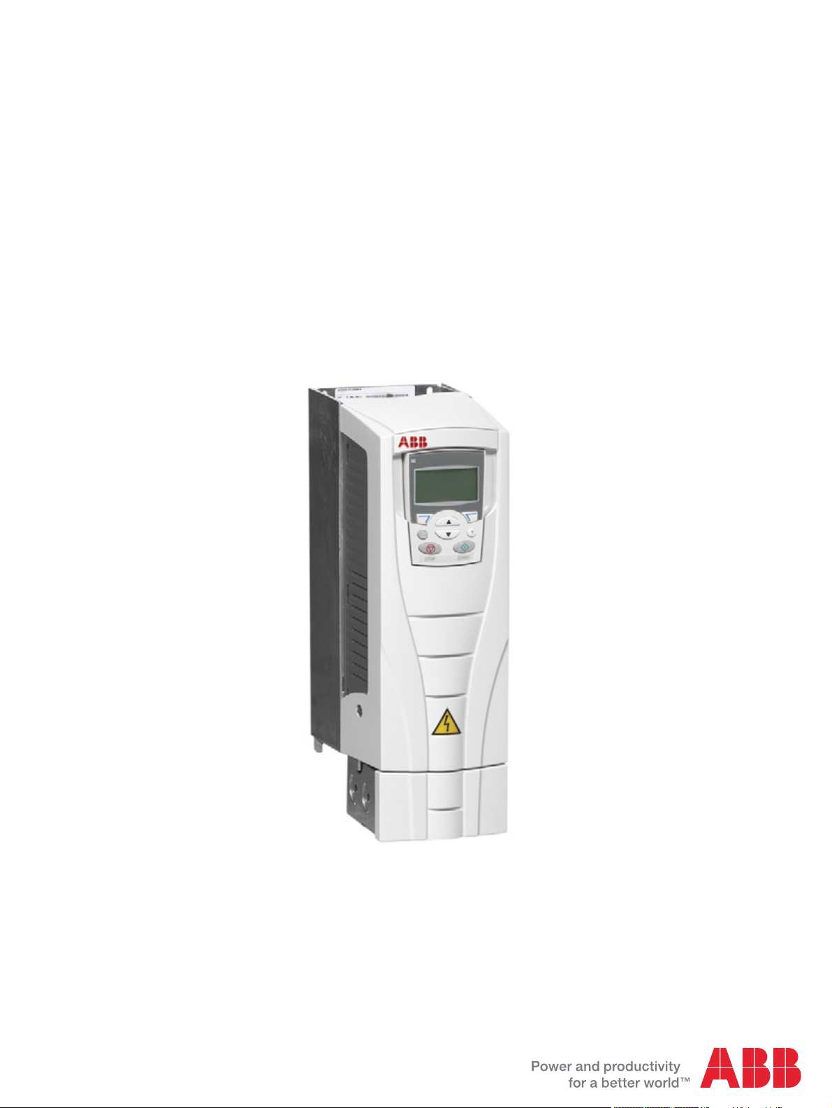
ACS550
User’s Manual
ACS550-01 Drives (0.75
ACS550-U1 Drives (1
…200 hp)
…160 kW)
Page 2

Kit, IP21 / UL type 1 Frame size Code (English)
FMK-A-R1 R1 100000982
FMK-A-R2 R2 100000984
FMK-A-R3 R3 100000986
FMK-A-R4 R4 100000988
AC8-FLNGMT-R5
1
R5
ACS800PNTG01U-ENAC8-FLNGMT-R6
1
R6
1. Not available for ACS550-01 series
Kit, IP54 / UL type 12 Frame size Code (English)
FMK-B-R1 R1 100000990
FMK-B-R2 R2 100000992
FMK-B-R3 R3 100000994
FMK-B-R4 R4 100000996
CANopen is a registered trademark of CAN in Automation
e.V.
ControlNet™ is a trademark of ODVA™.
DeviceNet™ is a trademark of ODVA™.
DRIVECOM is a registered trademark of DRIVECOM User
Group e.V.
EtherCAT® is registered trademark and patented
technology, licensed by Beckhoff Automation GmbH,
Germany.
EtherNet/IP™ is a trademark of ODVA™.
ETHERNET POWERLINK is a trademark of Bernecker +
Rainer Industrie-ElektronikGes.m.b.H.
Modbus and Modbus/TCP are registered trademarks of
Schneider Automation Inc.
PROFIBUS, PROFIBUS DP and PROFINET IO are
registered trademarks of Profibus International.
List of related manuals
GENERAL MANUALS
ACS550-01/U1 User's Manual (0.75…160 kW) /
(1…200 hp)
3AFE64804588 (3AUA0000001418) (English)
Flange Mounting Instructions
OPTION MANUALS
(delivered with optional equipment)
RPBA-01 PROFIBUS DP Adapter User's Manual
3AFE64504215 (English)
SREA-01 Ethernet Adapter User's Manual
3AUA0000042896 (English)
Typical contents
•Safety
• Installation
• Programming/Start-up
• Diagnostics
• Technical data
MAINTENANCE MANUALS
Guide for Capacitor Reforming in ACS50, ACS55,
ACS150, ACS310, ACS350, ACS355, ACS550, ACH550
and R1-R4 OINT-/SINT-boards
3AFE68735190 (English)
ACS550-01 manuals
MFDT-01 FlashDrop User's Manual
3AFE68591074 (English)
OHDI-01 115/230 V Digital Input Module User's Manual
3AUA0000003101 (English)
OREL-01 Relay Output Extension Module User's
Manual
3AUA0000001935 (English)
OTAC-01 User’s Manual Pulse Encoder Interface
Module User’s Manual
3AUA0000001938 (English)
RCAN-01 CANopen Adapter User's Manual
3AFE64504231 (English)
RCNA-01 ControlNet Adapter User's Manual
3AFE64506005 (English)
RDNA-01 DeviceNet Adapter User's Manual
3AFE64504223 (English)
RECA-01 EtherCAT Adapter Module User's Manual
3AUA0000043520 (English)
REPL-01 Ethernet POWERLINK Adapter Module
User's Manual
3AUA0000052289 (English)
REPL-02 Ethernet POWERLINK Adapter Module
User's Manual
3AUA0000090411 (English)
RETA-01 Ethernet Adapter Module User's Manual
3AFE64539736 (English)
RETA-02 Ethernet Adapter Module User's Manual
3AFE68895383 (English)
Page 3

ACS550-01/U1 Drives
0.75…160 kW
1…200 hp
User’s Manual
3AFE64804588 (3AUA0000001418) Rev H
EFFECTIVE: 2014-07-04
SUPERSEDES: 3AFE64804588 (3AUA0000001418) Rev G 2009-07-07
2014 ABB Oy. All Rights Reserved.
EN
Page 4

Page 5
ACS550-01/U1 User’s Manual 5
Safety instructions
Use of warnings and notes
There are two types of safety instructions throughout this manual:
• Notes draw attention to a particular condition or fact, or give information on a
subject.
• Warnings caution you about conditions which can result in serious injury or death
and/or damage to the equipment. They also tell you how to avoid the danger. The
warning symbols are used as follows:
Electricity warning warns of hazards from electricity which can cause physical
injury and/or damage to the equipment.
General warning warns about conditions, other than those caused by electricity,
which can result in physical injury and/or damage to the equipment.
General safety
WARNING! Obey these instructions. If you ignore them, injury or death, or damage
to the equipment can occur.
• Use safety shoes to avoid foot injury.
• Handle the drive carefully.
• Beware of hot surfaces. Some parts, such as heatsinks, remain hot for a while
after disconnection of the electrical supply. See chapter Technical data on page
277.
• Keep the drive in its package or protect it otherwise from dust and burr from
drilling and grinding until you install it. Protect also the installed drive against dust
and burr. Electrically conductive debris inside the drive can cause damage or
malfunction.
Electrical safety
WARNING! The ACS550 adjustable speed AC drive should ONLY be installed by a
qualified electrician.
WARNING! Even when the motor is stopped, dangerous voltage is present at the
power circuit terminals U1, V1, W1 and U2, V2, W2 and, depending on the frame
size, UDC+ and UDC-, or BRK+ and BRK-.
Safety instructions
Page 6
6 ACS550-01/U1 User’s Manual
WARNING! Dangerous voltage is present when input power is connected. After
disconnecting the supply, wait at least 5 minutes (to let the intermediate circuit
capacitors discharge) before removing the cover.
WARNING! Even when power is switched off from the input terminals of the
ACS550, there may be dangerous voltage (from external sources) on the terminals
of the relay outputs RO1…RO3.
WARNING! When the control terminals of two or more drives are connected in
parallel, the auxiliary voltage for these control connections must be taken from a
single source which can either be one of the drives or an external supply.
WARNING! If you install the drive on an IT system (an ungrounded power system or
a high-resistance-grounded [over 30 ohms] power system), disconnect the internal
EMC filter, otherwise the system will be connected to ground potential through the
EMC filter capacitors. This can cause danger or damage the drive.
Maintenance
If you install the drive on a corner-grounded TN system, disconnect the internal EMC
filter, otherwise the system will be connected to ground potential through the EMC
filter capacitors. This will damage the drive.
Note: Disconnecting the internal EMC filter increases the conducted emission and
reduces the drive EMC compatibility considerably.
See section Disconnecting the internal EMC filter on page 27. Also see sections IT
systems on page 286 and Corner-grounded TN systems on page 285.
WARNING! Do not attempt to install or remove EM1, EM3, F1 or F2 screws while
power is applied to the drive’s input terminals.
WARNING! The ACS550-01/U1 is not field repairable. Never attempt to repair a
malfunctioning drive; contact your local ABB representative for replacement.
Safety instructions
Page 7

ACS550-01/U1 User’s Manual 7
Control of the drive and motor
WARNING! Do not control the motor with the disconnecting device (disconnecting
means); instead, use the control panel start and stop keys and , or
commands via the I/O board of the drive. The maximum allowed number of charging
cycles of the DC capacitors (i.e. power-ups by applying power) is five in ten minutes.
WARNING! The ACS550 will start up automatically after an input voltage interruption
if the external run command is on.
Note: For more technical information, contact your local ABB representative.
Safety instructions
Page 8

8 ACS550-01/U1 User’s Manual
Safety instructions
Page 9

ACS550-01/U1 User’s Manual 9
Table of contents
List of related manuals
Safety instructions
Use of warnings and notes . . . . . . . . . . . . . . . . . . . . . . . . . . . . . . . . . . . . . . . . . 5
General safety . . . . . . . . . . . . . . . . . . . . . . . . . . . . . . . . . . . . . . . . . . . . . . . . . . 5
Electrical safety . . . . . . . . . . . . . . . . . . . . . . . . . . . . . . . . . . . . . . . . . . . . . . . . . 5
Maintenance . . . . . . . . . . . . . . . . . . . . . . . . . . . . . . . . . . . . . . . . . . . . . . . . . . . . 6
Control of the drive and motor . . . . . . . . . . . . . . . . . . . . . . . . . . . . . . . . . . . . . . 7
Table of contents
Contents of this manual
Compatibility . . . . . . . . . . . . . . . . . . . . . . . . . . . . . . . . . . . . . . . . . . . . . . . . . . . 13
Intended use . . . . . . . . . . . . . . . . . . . . . . . . . . . . . . . . . . . . . . . . . . . . . . . . . . . 13
Intended audience . . . . . . . . . . . . . . . . . . . . . . . . . . . . . . . . . . . . . . . . . . . . . . 13
Installation
Installation flow chart . . . . . . . . . . . . . . . . . . . . . . . . . . . . . . . . . . . . . . . . . . . . 15
Preparing for installation . . . . . . . . . . . . . . . . . . . . . . . . . . . . . . . . . . . . . . . . . . 16
Installing the drive . . . . . . . . . . . . . . . . . . . . . . . . . . . . . . . . . . . . . . . . . . . . . . 20
Start-up, control with I/O and ID Run
How to start up the drive . . . . . . . . . . . . . . . . . . . . . . . . . . . . . . . . . . . . . . . . . 37
How to control the drive through the I/O interface . . . . . . . . . . . . . . . . . . . . . . 44
How to perform the ID Run . . . . . . . . . . . . . . . . . . . . . . . . . . . . . . . . . . . . . . . . 45
Control panels
About control panels . . . . . . . . . . . . . . . . . . . . . . . . . . . . . . . . . . . . . . . . . . . . . 47
Compatibility . . . . . . . . . . . . . . . . . . . . . . . . . . . . . . . . . . . . . . . . . . . . . . . . . . . 47
Assistant Control Panel . . . . . . . . . . . . . . . . . . . . . . . . . . . . . . . . . . . . . . . . . . 48
Basic Control Panel . . . . . . . . . . . . . . . . . . . . . . . . . . . . . . . . . . . . . . . . . . . . . 68
Application macros
ABB Standard macro . . . . . . . . . . . . . . . . . . . . . . . . . . . . . . . . . . . . . . . . . . . . 78
3-wire macro . . . . . . . . . . . . . . . . . . . . . . . . . . . . . . . . . . . . . . . . . . . . . . . . . . . 79
Alternate macro . . . . . . . . . . . . . . . . . . . . . . . . . . . . . . . . . . . . . . . . . . . . . . . . 80
Motor Potentiometer macro . . . . . . . . . . . . . . . . . . . . . . . . . . . . . . . . . . . . . . . 81
Hand-Auto macro . . . . . . . . . . . . . . . . . . . . . . . . . . . . . . . . . . . . . . . . . . . . . . . 82
PID Control macro . . . . . . . . . . . . . . . . . . . . . . . . . . . . . . . . . . . . . . . . . . . . . . 83
PFC macro . . . . . . . . . . . . . . . . . . . . . . . . . . . . . . . . . . . . . . . . . . . . . . . . . . . . 84
Torque Control macro . . . . . . . . . . . . . . . . . . . . . . . . . . . . . . . . . . . . . . . . . . . 85
Connection examples of two-wire and three-wire sensors . . . . . . . . . . . . . . . . 86
Connection for obtaining 0…10 V from analog outputs . . . . . . . . . . . . . . . . . . 87
User parameter sets . . . . . . . . . . . . . . . . . . . . . . . . . . . . . . . . . . . . . . . . . . . . . 88
Table of contents
Page 10

10 ACS550-01/U1 User’s Manual
Macro default values for parameters . . . . . . . . . . . . . . . . . . . . . . . . . . . . . . . . 89
Parameters
Complete parameter list . . . . . . . . . . . . . . . . . . . . . . . . . . . . . . . . . . . . . . . . . . 91
Complete parameter descriptions . . . . . . . . . . . . . . . . . . . . . . . . . . . . . . . . . . 106
Embedded fieldbus
Overview . . . . . . . . . . . . . . . . . . . . . . . . . . . . . . . . . . . . . . . . . . . . . . . . . . . . . 203
Planning . . . . . . . . . . . . . . . . . . . . . . . . . . . . . . . . . . . . . . . . . . . . . . . . . . . . . 204
Mechanical and electrical installation – EFB . . . . . . . . . . . . . . . . . . . . . . . . . 204
Communication set-up – EFB . . . . . . . . . . . . . . . . . . . . . . . . . . . . . . . . . . . . . 205
Activate drive control functions – EFB . . . . . . . . . . . . . . . . . . . . . . . . . . . . . . 207
Feedback from the drive – EFB . . . . . . . . . . . . . . . . . . . . . . . . . . . . . . . . . . . 211
Diagnostics – EFB . . . . . . . . . . . . . . . . . . . . . . . . . . . . . . . . . . . . . . . . . . . . . 212
Modbus protocol technical data . . . . . . . . . . . . . . . . . . . . . . . . . . . . . . . . . . . 215
ABB control profiles technical data . . . . . . . . . . . . . . . . . . . . . . . . . . . . . . . . . 224
Fieldbus adapter
Overview . . . . . . . . . . . . . . . . . . . . . . . . . . . . . . . . . . . . . . . . . . . . . . . . . . . . . 237
Planning . . . . . . . . . . . . . . . . . . . . . . . . . . . . . . . . . . . . . . . . . . . . . . . . . . . . . 239
Mechanical and electrical installation – FBA . . . . . . . . . . . . . . . . . . . . . . . . . 240
Communication set-up – FBA . . . . . . . . . . . . . . . . . . . . . . . . . . . . . . . . . . . . . 241
Activate drive control functions – FBA . . . . . . . . . . . . . . . . . . . . . . . . . . . . . . 241
Feedback from the drive – FBA . . . . . . . . . . . . . . . . . . . . . . . . . . . . . . . . . . . 244
Diagnostics – FBA . . . . . . . . . . . . . . . . . . . . . . . . . . . . . . . . . . . . . . . . . . . . . 245
ABB Drives profile technical data . . . . . . . . . . . . . . . . . . . . . . . . . . . . . . . . . . 248
Generic profile technical data . . . . . . . . . . . . . . . . . . . . . . . . . . . . . . . . . . . . . 256
Diagnostics
Diagnostic displays . . . . . . . . . . . . . . . . . . . . . . . . . . . . . . . . . . . . . . . . . . . . . 259
Correcting faults . . . . . . . . . . . . . . . . . . . . . . . . . . . . . . . . . . . . . . . . . . . . . . . 260
Correcting alarms . . . . . . . . . . . . . . . . . . . . . . . . . . . . . . . . . . . . . . . . . . . . . . 266
Maintenance
Maintenance intervals . . . . . . . . . . . . . . . . . . . . . . . . . . . . . . . . . . . . . . . . . . . 271
Heatsink . . . . . . . . . . . . . . . . . . . . . . . . . . . . . . . . . . . . . . . . . . . . . . . . . . . . . 271
Main fan replacement . . . . . . . . . . . . . . . . . . . . . . . . . . . . . . . . . . . . . . . . . . . 272
Internal enclosure fan replacement . . . . . . . . . . . . . . . . . . . . . . . . . . . . . . . . 274
Capacitors . . . . . . . . . . . . . . . . . . . . . . . . . . . . . . . . . . . . . . . . . . . . . . . . . . . . 275
Control panel . . . . . . . . . . . . . . . . . . . . . . . . . . . . . . . . . . . . . . . . . . . . . . . . . 275
Technical data
Ratings . . . . . . . . . . . . . . . . . . . . . . . . . . . . . . . . . . . . . . . . . . . . . . . . . . . . . . 277
Input power connections . . . . . . . . . . . . . . . . . . . . . . . . . . . . . . . . . . . . . . . . . 281
Motor connections . . . . . . . . . . . . . . . . . . . . . . . . . . . . . . . . . . . . . . . . . . . . . 289
Brake components . . . . . . . . . . . . . . . . . . . . . . . . . . . . . . . . . . . . . . . . . . . . . 295
Control connections . . . . . . . . . . . . . . . . . . . . . . . . . . . . . . . . . . . . . . . . . . . . 299
Efficiency . . . . . . . . . . . . . . . . . . . . . . . . . . . . . . . . . . . . . . . . . . . . . . . . . . . . 300
Losses, cooling data and noise . . . . . . . . . . . . . . . . . . . . . . . . . . . . . . . . . . . 301
Table of contents
Page 11

ACS550-01/U1 User’s Manual 11
Dimensions and weights . . . . . . . . . . . . . . . . . . . . . . . . . . . . . . . . . . . . . . . . 303
Degrees of protection . . . . . . . . . . . . . . . . . . . . . . . . . . . . . . . . . . . . . . . . . . . 306
Ambient conditions . . . . . . . . . . . . . . . . . . . . . . . . . . . . . . . . . . . . . . . . . . . . . 307
Materials . . . . . . . . . . . . . . . . . . . . . . . . . . . . . . . . . . . . . . . . . . . . . . . . . . . . . 308
Applicable standards . . . . . . . . . . . . . . . . . . . . . . . . . . . . . . . . . . . . . . . . . . . 309
Markings . . . . . . . . . . . . . . . . . . . . . . . . . . . . . . . . . . . . . . . . . . . . . . . . . . . . . 309
IEC/EN 61800-3:2004 Definitions . . . . . . . . . . . . . . . . . . . . . . . . . . . . . . . . . 311
Compliance with the IEC/EN 61800-3:2004 +A1:2012 . . . . . . . . . . . . . . . . . 311
Index
Further information
Product and service inquiries . . . . . . . . . . . . . . . . . . . . . . . . . . . . . . . . . . . . . 325
Product training . . . . . . . . . . . . . . . . . . . . . . . . . . . . . . . . . . . . . . . . . . . . . . . 325
Providing feedback on ABB Drives manuals . . . . . . . . . . . . . . . . . . . . . . . . . 325
Document library on the Internet . . . . . . . . . . . . . . . . . . . . . . . . . . . . . . . . . . 325
Table of contents
Page 12

12 ACS550-01/U1 User’s Manual
Table of contents
Page 13

ACS550-01/U1 User’s Manual 13
Contents of this manual
Compatibility
This manual covers ACS550-01/U1 drives. The manual is compatible with the
ACS550-01/U1 drive firmware version 3.14e or later. See parameter 3301
FIRMWARE on page 155.
Intended use
The ACS550-01/U1 is a general purpose drive. The macros should only be applied
to the applications defined in the respective section.
Intended audience
This manual is intended for personnel who install, commission, operate and service
the drive. Read the manual before working on the drive. The reader is expected to
know the fundamentals of electricity, wiring, electrical components and electrical
schematic symbols.
Contents of this manual
Page 14

14 ACS550-01/U1 User’s Manual
Contents of this manual
Page 15
ACS550-01/U1 User’s Manual 15
Installation
Study these installation instructions carefully before proceeding. Failure to observe
the warnings and instructions may cause a malfunction or personal hazard.
WARNING! Before you begin read chapter Safety instructions on page 5.
Note: The installation must always be designed and made according to applicable
local laws and regulations. ABB does not assume any liability whatsoever for any
installation which breaches the local laws and/or other regulations. Furthermore, if
the recommendations given by ABB are not followed, the drive may experience
problems that the warranty does not cover.
Installation flow chart
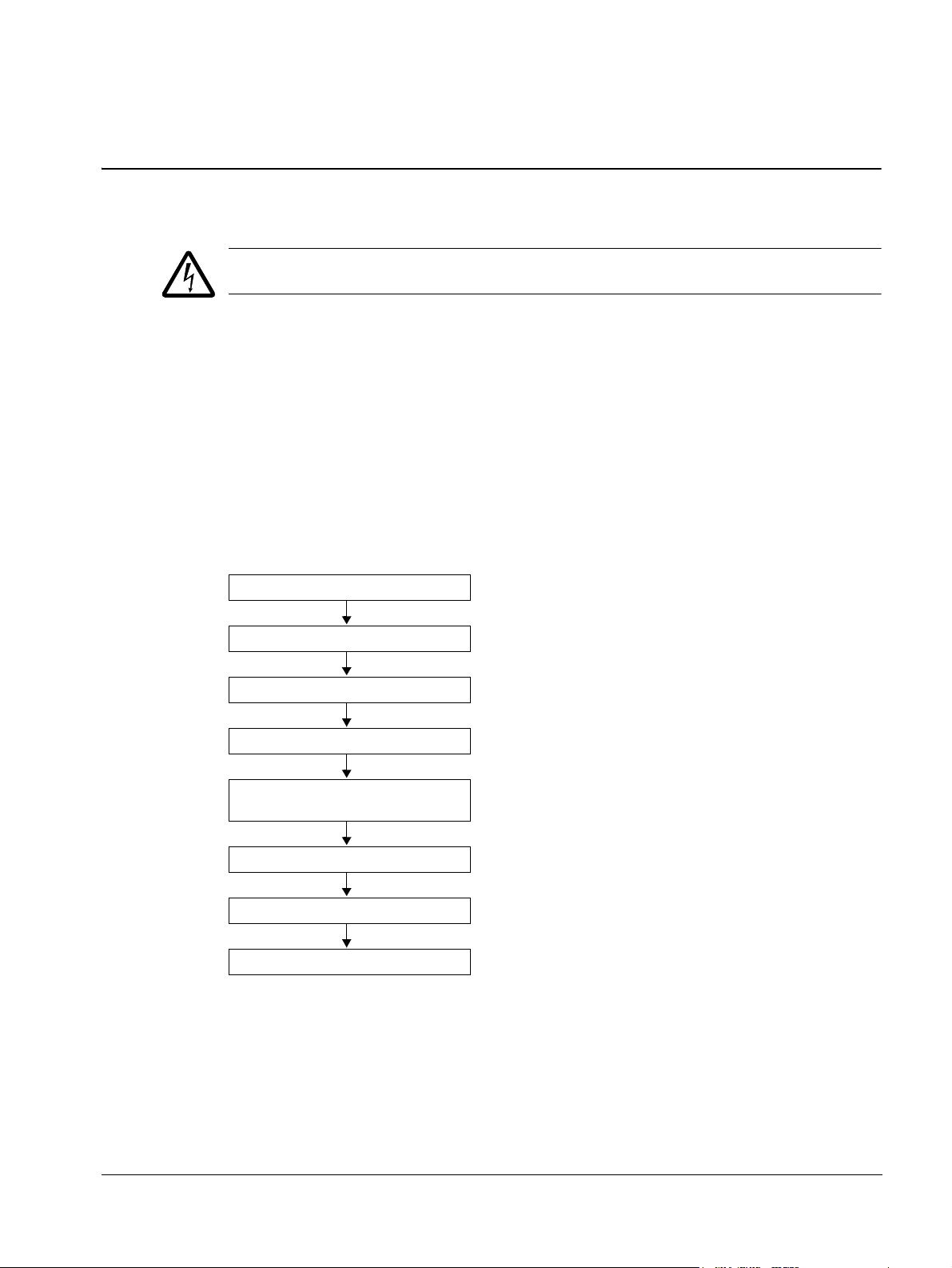
The installation of the ACS550 adjustable speed AC drive follows the outline below.
The steps must be carried out in the order shown. At the right of each step are
references to the detailed information needed for the correct installation of the drive.
Task See
PREPARE for installation Preparing for installation on page 16
PREPARE the mounting location Prepare the mounting location on page 20
REMOVE the front cover Remove the front cover on page 21
MOUNT the drive Mount the drive on page 22
INSTALL wiring Wiring overview on page 23 and
CHECK installation Check installation on page 35
REINSTALL the cover Reinstall the cover on page 36
START-UP How to start up the drive on page 37
Check the insulation of the assembly on page 30
Installation
Page 16
16 ACS550-01/U1 User’s Manual
IP2040
Serial number
Type designation
Serial number
Type designation
Type designation
Serial number
Preparing for installation
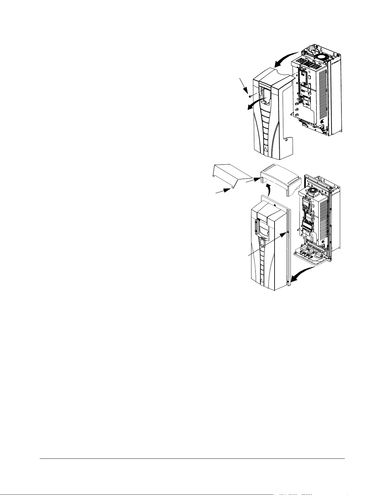
Lifting the drive
Lift the drive only by the metal
chassis.
Unpacking the drive
1. Unpack the drive.
2. Check for any damage and
notify the shipper immediately
if damaged components are
found.
3. Check the contents against
the order and the shipping label to verify that all parts have been received.
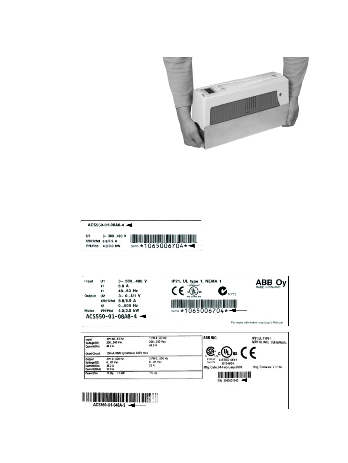
Drive identification
Drive labels
To determine the type of drive you are installing, refer to either:
• serial number label attached on upper part of the choke plate between the
mounting holes, or
• type designation label attached on the heat sink – on the right side of the drive
cover. Two examples of the type designation label are given below.
Installation
Page 17

ACS550-01/U1 User’s Manual 17
AC, Standard Drive – 550 product series
Construction (region specific)
Output current rating
Voltage rating
Options
Examples of options:
B055 = IP54 / UL type 12 (no specification = IP21 / UL type 1).
UL type 12 is not available for type ACS550-01-290A-4.
0J400 = No control panel
J404 = ACS-CP-C Basic Control Panel
L511 = OREL-01 Relay output extension
K451 = RDNA-01 DeviceNet
K454 = RPBA-01 PROFIBUS DP
ACS550-01-08A8-4+J404+…
e.g. 08A8 = 8.8 A, see section Ratings on page 277 for details
2 = 208…240 VAC
4 = 380…480 VAC
6 = 500…600 V AC
01 = Setup and parts specific to IEC installation and compliance
U1= Setup and parts specific to US installation and NEMA compliance
The labels contain information on the Type designation (page 17), Ratings and frame
size (page 17), Serial number (page 17), degree of protection (see also Degrees of
protection on page 306) and valid markings (see also Markings on page 309).
Type designation
Use the following chart to interpret the type designation found on both the type
designation and the serial number label.
Ratings and frame size
The chart in section Ratings
the drive’s frame size – significant, since some instructions in this document vary,
depending on the drive’s frame size. To read the ratings table, you need the “Output
current rating” entry from the type designation. Also, when using the ratings table,
note that the table is broken into sections based on the drive’s “Voltage rating”.
Serial number
The format of the drive serial number shown on the labels is described below.
Serial number is of format CYYWWXXXXX, where
C: Country of manufacture
YY: Year of manufacture
WW: Week of manufacture; 01, 02, 03, … for week 1, week 2, week 3, …
XXXXX: Integer starting every week from 00001.
on page 277 lists technical specifications and identifies
Installation
Page 18

18 ACS550-01/U1 User’s Manual
Motor compatibility
The motor, drive and supply power must be compatible:
Motor
specification
Motor type 3-phase induction motor –
Nominal current Motor value is within this
Nominal frequency 10…500 Hz –
Voltage range Motor is compatible with
Insulation 500…600 V drives: Either
range: 0.2…2.0 · I
(I
2hd
current)
the ACS550 voltage range.
the motor complies with
NEMA MG1 Part 31, or a
du/dt filter is used between
the motor and drive.
Ver ify Refe rence
• Type designation label on drive, entry for
= drive heavy duty
2hd
Output I
• Type designation on drive and rating table in
chapter Technical data on page 277.
208…240 V (for ACS550-X1-XXXX-2) or
380…480 V (for ACS550-X1-XXXX-4) or
500…600 V (for ACS550-U1-XXXX-6)
For ACS550-U1-XXXX-6
2hd
Tools required
To install the ACS550 you need the following:
• screwdrivers (as appropriate for the mounting hardware used)
• wire stripper
• tape measure
, or
• drill
• for installations involving ACS550-U1, frame sizes R5 or R6 and IP54 / UL type
12 enclosures: punch for creating conduit mounting holes
• for installations involving ACS550-U1, frame size R6: appropriate crimping tool
for power cable lugs. See section Power terminal considerations – R6 frame size
on page 287.
• mounting hardware: screws or nuts and bolts, four each. The type of hardware
depends on the mounting surface and the frame size. For the dimensions and
weights of the frames, see Dimensions and weights on page 303.
Frame size Mounting hardware
R1…R4 M5
R5 M6
R6 M8
#10
1/4 in
5/16 in
Suitable environment and enclosure
Confirm that the site meets the environmental requirements. To prevent damage
prior to installation, store and transport the drive according to the environmental
requirements specified for storage and transportation. See section Ambient
conditions
on page 307.
Installation
Page 19

ACS550-01/U1 User’s Manual 19
Confirm that the enclosure is appropriate, based on the site contamination level:
• IP21 / UL type 1 enclosure: The site must be free of airborne dust, corrosive
gases or liquids, and conductive contaminants such as dripping water,
condensation, carbon dust and metallic particles.
• IP54 / UL type 12 enclosure: This enclosure provides protection from airborne
dust and light sprays or splashing water from all directions.
• If, for some reason, an IP21 drive needs to be installed without the conduit box or
cover, or an IP54 drive without the conduit plate or hood, see the note in chapter
Technical data, page 310.
Suitable mounting location
Confirm that the mounting location meets the following constraints:
• The drive must be mounted vertically on a smooth, solid surface, and in a suitable
environment as defined above. For horizontal installation, contact your local ABB
representative for more information.
• The minimum space requirements for the drive are the outside dimensions (see
section Outside dimensions on page
304), plus air flow space around the drive
(see section Losses, cooling data and noise on page 301).
• The distance between the motor and the drive is limited by the maximum motor
cable length. See section Motor connection specifications
on page 289.
• The mounting site must support the drive’s modest weight. See section Weight on
page 306.
Installation
Page 20

20 ACS550-01/U1 User’s Manual
X0002
1
Installing the drive
WARNING! Before installing the ACS550, ensure the input power supply to the drive
is off.
For flange mounting (mounting the drive in a cooling air duct), see the appropriate
Flange Mounting Instructions:
Frame size
R1 FMK-A-R1 100000982 FMK-B-R1 100000990
R2 FMK-A-R2 100000984 FMK-B-R2 100000992
R3 FMK-A-R3 100000986 FMK-B-R3 100000994
R4 FMK-A-R4 100000988 FMK-B-R4 100000996
R5 AC8-FLNGMT-R5
R6 AC8-FLNGMT-R6
1. Not available in ACS550-01 series.
IP21 / UL type 1 IP54 / UL type 12
Kit Code (English) Kit Code (English)
1
ACS800-PNTG01U-EN--
1
--
Prepare the mounting location
The ACS550 should only be mounted where all of the
requirements defined in section Preparing for installation
on page 16 are met.
1. Mark the position of the mounting holes with the help of
the mounting template provided with the drive.
2. Drill the holes.
Note: Frame sizes R3 and R4 have four holes along the top. Use only two. If
possible, use the two outside holes (to allow room to remove the fan for
maintenance).
Note: ACS400 drives can be replaced using the original mounting holes. For R1 and
R2 frame sizes, the mounting holes are identical. For R3 and R4 frame sizes, the
inside mounting holes on the top of ACS550 drives match ACS400 mounts.
Installation
Page 21
ACS550-01/U1 User’s Manual 21
3
IP2000
1
2
3
4
1
2
FM
R6
1
R1
…R5
Remove the front cover
IP21 / UL type 1
1. Remove the control panel, if attached.
2. Loosen the captive screw at the top.
3. Pull near the top to remove the cover.
IP54 / UL type 12
1. If hood is present: Remove screws
(2) holding hood in place.
2. If hood is present: Slide hood up and
off of the cover.
3. Loosen the captive screws around
the edge of the cover.
4. Remove the cover.
Installation
Page 22
22 ACS550-01/U1 User’s Manual
IP2002
1
2
3
1, 4
FM
5
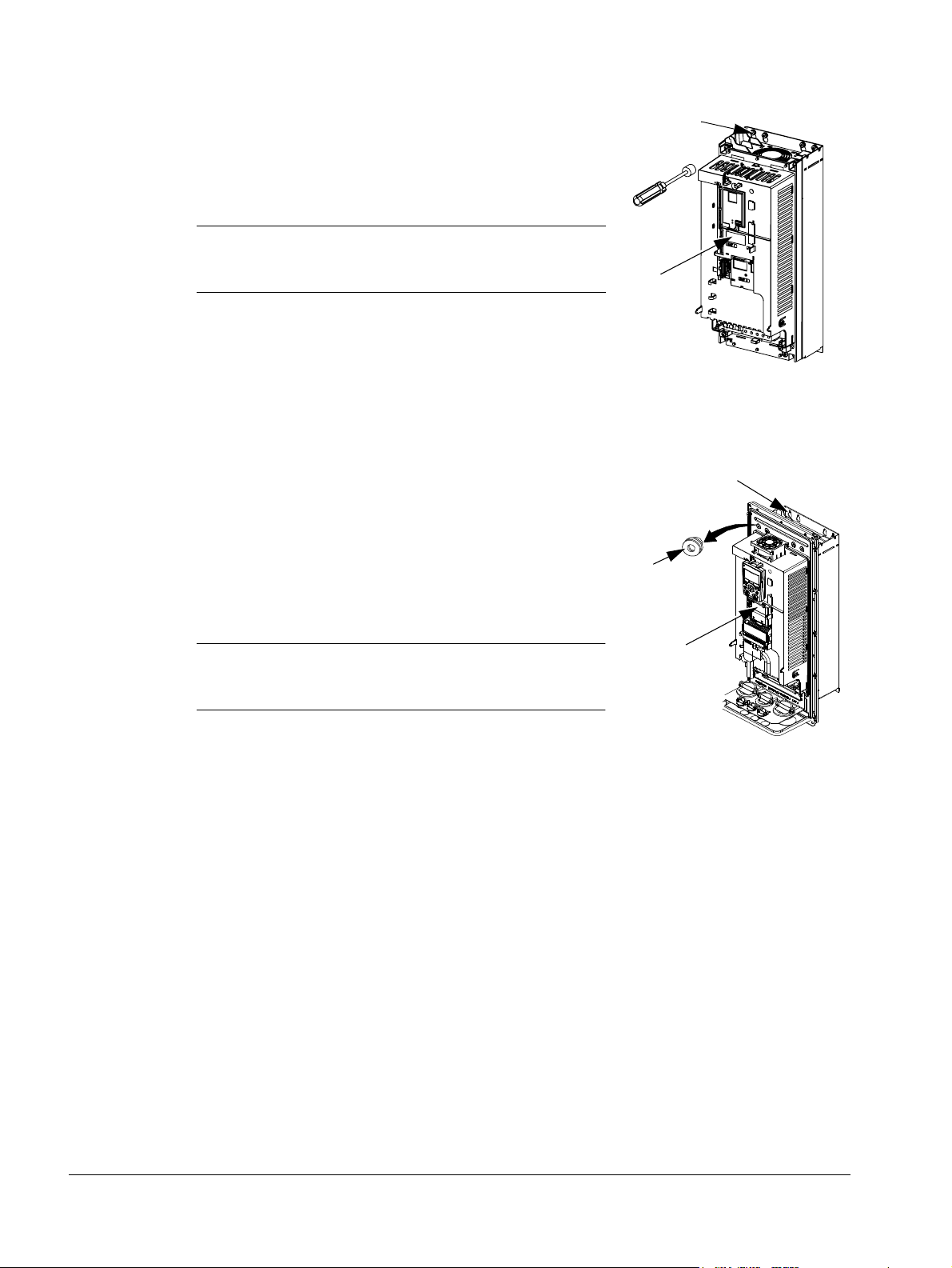
Mount the drive
IP21 / UL type 1
1. Position the ACS550 onto the mounting screws or
bolts and securely tighten in all four corners.
Note: Lift the ACS550 by its metal chassis (frame
size R6 by the lifting holes on both sides at the top).
2. Non-English speaking locations: Add a warning
sticker in the appropriate language over the existing
warning on the top of the module.
IP54 / UL type 12
For the IP54 / UL type 12 enclosures, rubber plugs are required in the holes
provided for access to the drive mounting slots.
1. As required for access, remove the rubber plugs.
Push plugs out from the back of the drive.
2. R5 & R6: Align the sheet metal hood (not shown) in
front of the drive’s top mounting holes. (Attach as
part of next step.)
3. Position the ACS550 onto the mounting screws or
bolts and securely tighten in all four corners.
Note: Lift the ACS550 by its metal chassis (frame
size R6 by the lifting holes on both sides at the top).
4. Reinstall the rubber plugs.
5. Non-English speaking locations: Add a warning sticker in the appropriate language
over the existing warning on the top of the module.
Installation
Page 23

ACS550-01/U1 User’s Manual 23
Wiring overview
Conduit/Gland kit
Wiring drives with the IP21 / UL type 1 enclosure requires a conduit/gland kit with the
following items:
• conduit/gland box
• five (5) cable clamps (ACS550-01 only)
• screws
•cover.
The kit is included with IP21 / UL type 1 enclosures.
Wiring requirements
WARNING! Ensure the motor is compatible for use with the ACS550. The drive must
be installed by a competent person in accordance with the considerations defined in
section Preparing for installation on page 16. If in doubt, contact your local ABB
representative.
As you install the wiring, observe the following:
• There are four sets of wiring instructions – one set for each combination of drive
enclosure type (IP21 / UL type and IP54 / UL type 12) and wiring type (conduit or
cable). Be sure to select the appropriate procedure.
• Determine electro-magnetic compliance (EMC) requirements per local codes.
See section Motor cable requirements for CE & C-Tick compliance on page 293.
In general:
– Follow local codes for cable size.
– Keep these four classes of wiring separated: input power wiring, motor wiring,
control/communications wiring and braking unit wiring.
• When installing input power and motor wiring, refer to the following, as
appropriate:
Terminal Description Specifications and notes
U1, V1, W1
PE Protective Ground Ground connections on page 285
U2, V2, W2 Power output to motor Motor connections on page 289
1
The ACS550 -x1-xxxx-2 (208…240 V series) can be used with a single phase supply, if output
current is derated by 50%. For single phase supply voltage, connect power at U1 and W1.
1
3-phase power supply input Input power connections on page 281
• To locate input power and motor connection terminals, see section Power
connection diagrams on page 25. For specifications on power terminals, see
section Drive’s power connection terminals on page 286.
• For corner-grounded TN systems, see section Corner-grounded TN systems on
page 285.
• For IT systems, see section IT systems on page 286.
Installation
Page 24

24 ACS550-01/U1 User’s Manual
• For frame size R6, see section Power terminal considerations – R6 frame size on
page 287 to install the appropriate cable lugs.
• For drives using braking (optional), refer to the following, as appropriate:
Frame size Terminal Description Braking accessory
R1, R2 BRK+, BRK- Braking resistor Braking resistor. See section Brake
components on page 295.
R3, R4, R5, R6 UDC+, UDC- DC bus Contact your ABB representative to
order either:
• braking unit or
• chopper and resistor
• When installing control wiring, refer to the following chapters or sections, as
appropriate:
– Control terminals table on page 28
– Control connections
on page 299
– Application macros on page 77
– Complete parameter descriptions on page 106
– Embedded fieldbus on page 203
– Fieldbus adapter on page 237.
Installation
Page 25
ACS550-01/U1 User’s Manual 25
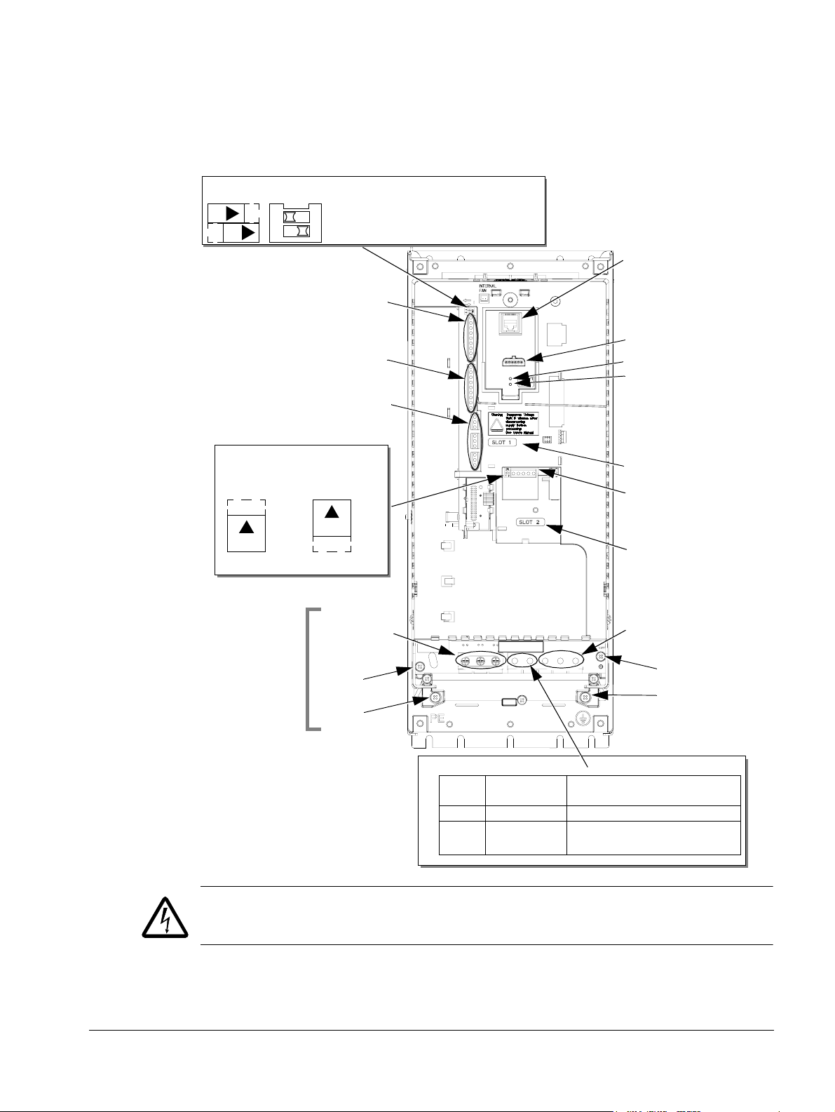
Panel connector
Fault LED (red)
Optional module 1
J2 – DIP switch
X1 – Communications
Optional module 2
GND
Power output to motor
Power input
EM1
X1 – Analog inputs and outputs
X1 – Digital inputs
X1 – Relay outputs
J2
ON
off position on position
for RS485 termination
(and 10 V ref. voltage output)
(and 24 V aux. voltage output)
PE
(U1, V1, W1)
(U2, V2, W2)
Optional braking
Frame
size
Term ina l
labels
Brake options
R1, R2 BRK+, BRK- Brake resistor
R3, R4 UDC+, UDC- • Braking unit
• Chopper and resistor
(RS485)
R5/R6 differ.
See
Frame sizes
next page.
Diagram shows the R3 frame.
J2
ON
Other frames have similar layouts.
J1
AI1: (in voltage position)
AI2: (in current position)
ON
ON
J1 – DIP switches for analog inputs (two types can be used)
ON
12
J1
FlashDrop option
Power LED (green)
3AUA0000001571
EM3
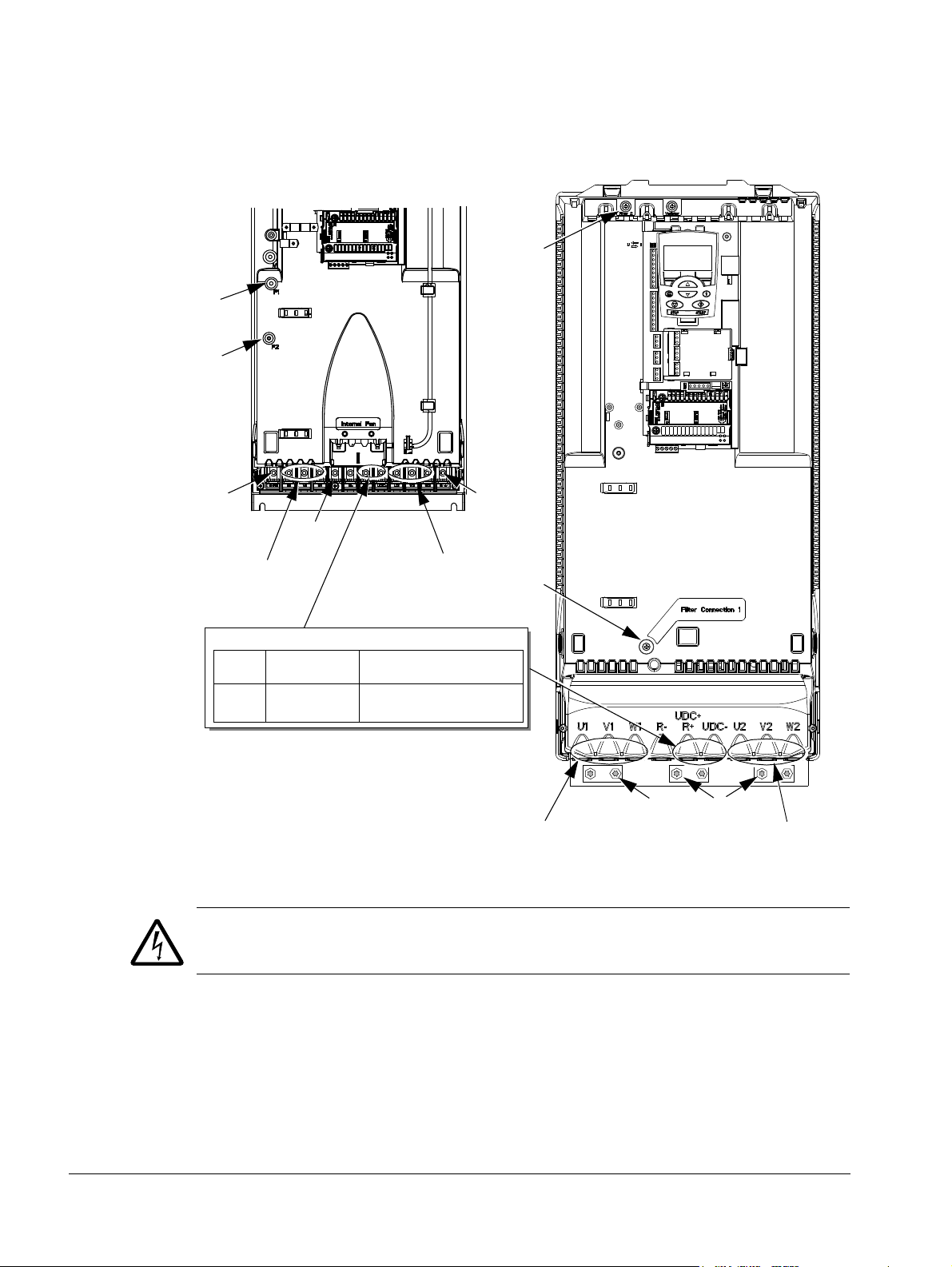
Power connection diagrams
The following diagram shows the terminal layout for frame size R3, which, in
general, applies to frame sizes R1
terminals.
…R6, except for the R5/R6 power and ground
WARNING! To avoid danger, or damage to the drive, on IT systems and cornergrounded TN systems, see section Disconnecting the internal EMC filter on page 27.
Installation
Page 26
26 ACS550-01/U1 User’s Manual
GND
Power input
PE
(U1, V1, W1)
Optional braking
Frame
size
Term ina l
labels
Brake options
R5, R6 UDC+, UDC- • Braking unit
• Chopper and resistor
X0011
F2
Power input
PE
(U1, V1, W1)
F1
F2
X0013
Power output to motor
(U2, V2, W2)
R5 R6
GND
GND
Power output to motor
(U2, V2, W2)
F1
The following diagram shows the power and ground terminal layout for frame sizes
R5 and R6end
WARNING! To avoid danger, or damage to the drive, on IT systems and cornergrounded TN systems, see section Disconnecting the internal EMC filter on page 27.
Installation
Page 27

ACS550-01/U1 User’s Manual 27
Disconnecting the internal EMC filter
On certain types of systems, you must disconnect the internal EMC filter, otherwise
the system will be connected to ground potential through the EMC filter capacitors,
which might cause danger, or damage the drive.
Note: Disconnecting the internal EMC filter increases the conducted emission and
reduces the drive EMC compatibility considerably.
The following table shows the installation rules for the EMC filter screws in order to
connect or disconnect the filter, depending on the system type and the frame size.
For more information on the different system types, see IT systems on page 286 and
Corner-grounded TN systems on page 285.
The locations of screws EM1 and EM3 are shown in the diagram on page 25. The
locations of screws F1 and F2 are shown in the diagram on page 26.
Frame
sizes
R1…R3
R4
R5…R6
x = Install the screw. (EMC filter will be connected.)
= Replace the screw with the provided polyamide screw. (EMC filter will be disconnected.)
–
= Remove the screw. (EMC filter will be disconnected.)
1
ACS550-U1 drives are shipped with screw EM3 already removed.
Screw
EM1 x x
1
EM3
EM1 x x –
1
EM3
F1 x x –
F2 x x –
Symmetrically
grounded TN systems
(TN-S systems)
x
x ––
Corner-grounded
TN systems
IT systems (ungrounded
or high-resistance-
grounded [> 30 ohm])
Installation
Page 28
28 ACS550-01/U1 User’s Manual
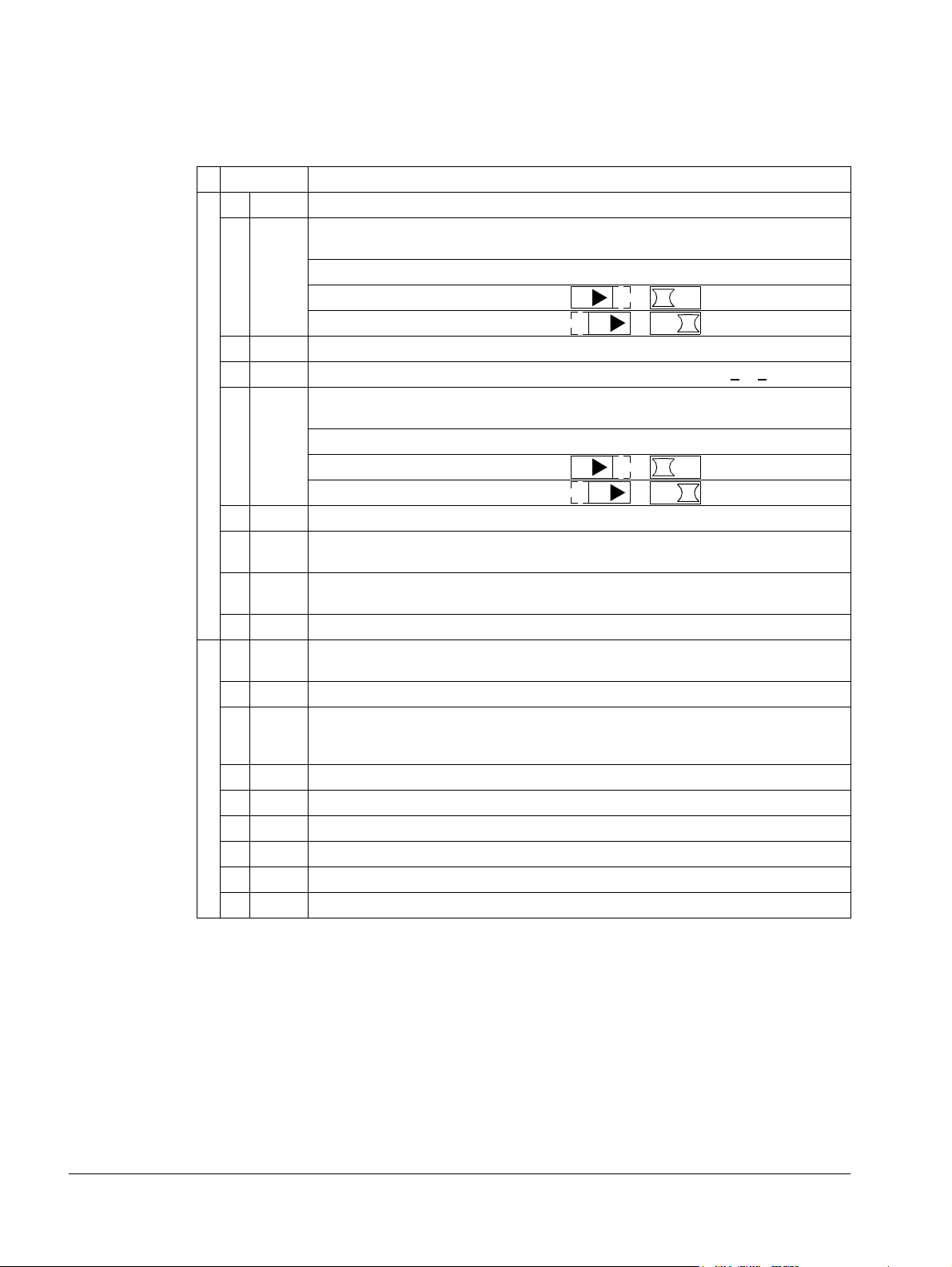
Analog I/O
ON
1
ON
ON
1
ON
ON
1
ON
ON
1
ON
Digital inputs
1
Control terminals table
The following provides information for connecting control wiring at X1 on the drive.
X1 Hardware description
1 SCR Terminal for signal cable shield (screen). (Connected internally to chassis ground.)
2
2 AI1 Analog input channel 1, programmable. Default
0.1%, accuracy ±1%.
Two different DIP switch types can be used.
J1: AI1 OFF: 0…10 V (R
J1: AI1 ON: 0…20 mA (R
= 312 kohm)
i
= 100 ohm)
i
3 AGND Analog input circuit common (connected internally to chassis gnd. through 1 Mohm).
4 +10 V Potentiometer reference source: 10 V ±2%, max. 10 mA (1 kohm <
5 AI2 Analog input channel 2, programmable. Default
accuracy ±1%.
Two different DIP switch types can be used.
J1: AI2 OFF: 0…10 V (R
J1: AI2 ON: 0…20 mA (R
= 312 kohm)
i
= 100 ohm)
i
6 AGND Analog input circuit common (connected internally to chassis gnd. through 1 Mohm).
7 AO1 Analog output, programmable. Default
2
= frequency. 0…20 mA (load < 500 ohm).
Accuracy ±3%.
8 AO2 Analog output, programmable. Default
2
= current. 0…20 mA (load < 500 ohm).
Accuracy ±3%.
9 AGND Analog output circuit common (connected internally to chassis gnd. through 1 Mohm).
10 +24V Auxiliary voltage output 24 V DC / 250 mA (reference to GND), short circuit
protected.
11 GND Auxiliary voltage output common (connected internally as floating).
12 DCOM Digital input common. To activate a digital input, there must be 10 V
(or -10 V) between that input and DCOM. The 24 V may be provided by the
ACS550 (X1-10) or by an external 12…24 V source of either polarity.
13 DI1 Digital input 1, programmable. Default
14 DI2 Digital input 2, programmable. Default
15 DI3 Digital input 3, programmable. Default
16 DI4 Digital input 4, programmable. Default
17 DI5 Digital input 5, programmable. Default
18 DI6 Digital input 6, programmable. Default
2
= start/stop.
2
=fwd/rev.
2
= constant speed sel (code).
2
= constant speed sel (code).
2
= ramp pair selection (code).
2
= not used.
= frequency reference. Resolution
R < 10 kohm).
2
= not used. Resolution 0.1%,
Installation
Page 29
ACS550-01/U1 User’s Manual 29
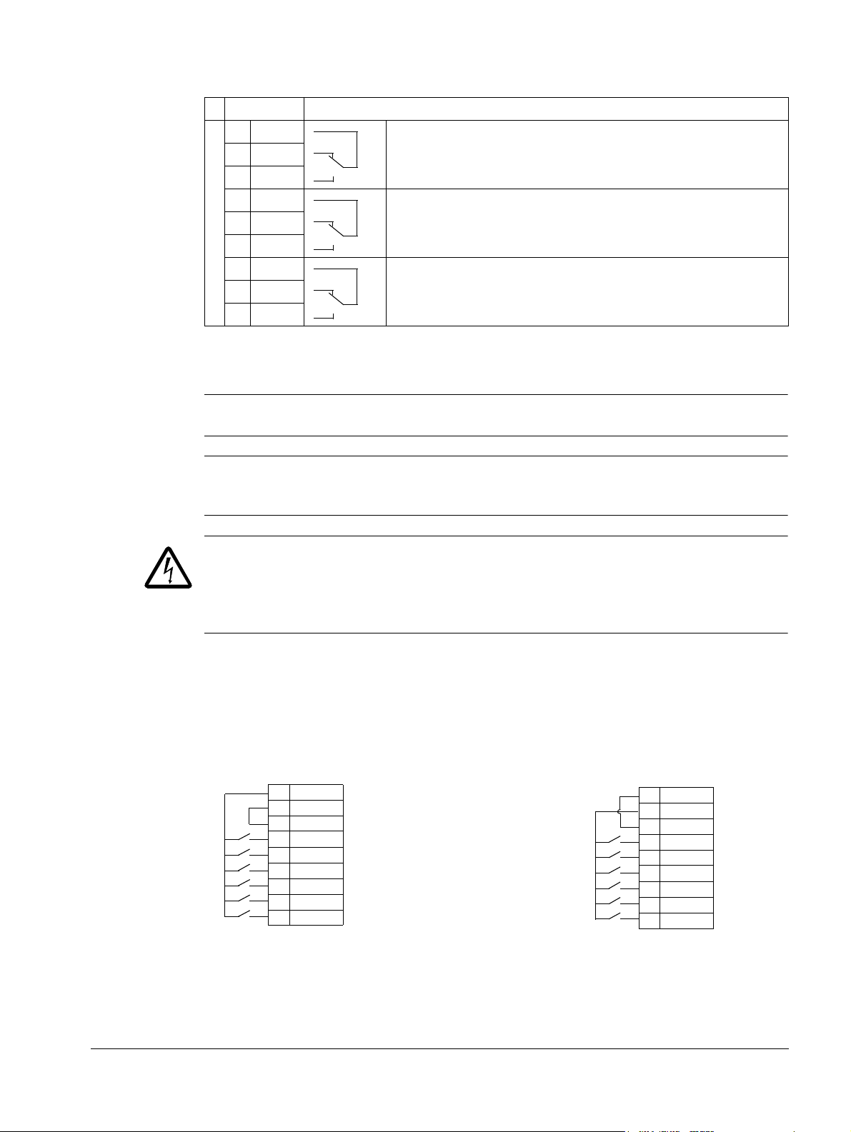
Relay outputs
NPN connection (sink)PNP connection (source)
10 +24V
11 GND
12 DCOM
13 DI1
14 DI2
15 DI3
16 DI4
17 DI5
18 DI6
10 +24V
11 GND
12 DCOM
13 DI1
14 DI2
15 DI3
16 DI4
17 DI5
18 DI6
X1
X1
X1 Hardware description
19 RO1C Relay output 1, programmable. Default2= Ready
20 RO1A
21 RO1B
22 RO2C Relay output 2, programmable. Default
23 RO2A
24 RO2B
25 RO3C Relay output 3, programmable. Default
26 RO3A
27 RO3B
1
Digital input impedance 1.5 kohm. Maximum voltage for digital inputs is 30 V.
2
Default values depend on the macro used. Values specified are for the default macro. See chapter
Application macros on page 77.
Maximum: 250 V AC / 30 V DC, 2 A
Minimum: 500 mW (12 V, 10 mA)
Maximum: 250 V AC / 30 V DC, 2 A
Minimum: 500 mW (12 V, 10 mA)
Maximum: 250 V AC / 30 V DC, 2 A
Minimum: 500 mW (12 V, 10 mA)
2
= Running
2
= Fault (-1)
Note: Terminals 3, 6 and 9 are at the same potential.
Note: For safety reasons the fault relay signals a “fault” when the ACS550 is
powered down.
WARNING! All ELV (Extra Low Voltage) circuits connected to the drive must be used
within a zone of equipotential bonding, i.e. within a zone where all simultaneously
accessible conductive parts are electrically connected to prevent hazardous voltages
appearing between them. This is accomplished by a proper factory grounding.
The terminals on the control board as well as on the optional modules attachable to
the board fulfil the Protective Extra Low Voltage (PELV) requirements stated in
EN 50178, provided that the external circuits connected to the terminals also fulfil
the requirements and the installation site is below 2000 m (6562 ft).
You can wire the digital input terminals in either a PNP or NPN configuration.
Installation
Page 30

30 ACS550-01/U1 User’s Manual
ohm
M
3~
U1
V1
W1
PE
1
2
X0004
Check the insulation of the assembly
Drive
Do not make any voltage tolerance or insulation resistance tests on any part of the
drive as testing can damage the drive. Every drive has been tested for insulation
between the main circuit and the chassis at the factory. Also, there are voltagelimiting circuits inside the drive which cut down the testing voltage automatically.
Supply cable
Check the insulation of the supply (input) cable according to local regulations before
connecting to the drive.
Motor and motor cable
Check the insulation of the motor and motor cable as follows:
1. Check that the motor cable is connected to the motor, and disconnected from the
drive output terminals U2, V2 and W2.
2. Measure the insulation resistance between phase
conductors and between each phase conductor and
the Protective Earth conductor using a measuring
voltage of 1000 V DC. The insulation resistance of an
ABB motor must exceed 100 Mohm (reference value
at 25 °C or 77 °F). For the insulation resistance of
other motors, please consult the manufacturer’s instructions. Note: Moisture inside
the motor casing will reduce the insulation resistance. If moisture is suspected, dry
the motor and repeat the measurement.
Install the wiring
Wiring IP21 / UL type 1 enclosure with cables
1. Open the appropriate knockouts in the conduit/gland
box. (See section Conduit/Gland kit on page 23.)
2. Install the cable clamps for the power/motor cables.
Installation
Page 31

ACS550-01/U1 User’s Manual 31
6
3
IP2001
6
7
4
8
8
X0005
Frame
size
Tightening torque
N·m
lb·ft
R1, R2 1.4
1
R3 2.5
1.8
R4 5.6; PE: 2
4; PE 1.5
R5 15
11
R6 40; PE: 8
30; PE: 6
9
X0006
12
IP2003
11
13
3. On the input power cable, strip the sheathing back far
enough to route individual wires.
4. On the motor cable, strip the sheathing back far
enough to expose the copper wire shield so that the
shield can be twisted into a bundle (pig-tail). Keep the
bundle not longer than five times its width to minimize
noise radiation.
360° grounding under the clamp is recommended for
the motor cable to minimize noise radiation. In this
case, remove the sheathing at the cable clamp.
5. Route both cables through the clamps.
6. Strip and connect the power/motor wires and the
power ground wire to the drive terminals. See the
table on the right for tightening torques.
Note: For R6 frame size, refer to section Power
terminal considerations – R6 frame size on page 287.
7. Connect the bundle (pig-tail) created from the motor
cable shield to the GND terminal.
8. Install conduit/gland box and tighten the cable clamps.
9. Install the cable clamp(s) for the control cable(s).
(Power/motor cables and clamps not shown in the
figure.)
10. Strip control cable sheathing and twist the copper
shield into a bundle (pig-tail).
11. Route control cable(s) through clamp(s) and tighten
clamp(s).
12. Connect the ground shield bundle (pig-tail) for digital and
analog I/O cables at X1-1. (Ground only at the drive end.)
13. Strip and connect the individual control wires to the
drive terminals. See section Control terminals table
on page 28. Use a tightening torque of 0.4 N·m
(0.3 lb·ft).
14. Install the conduit/gland box cover (1 screw).
Installation
Page 32

32 ACS550-01/U1 User’s Manual
2
X0007
3
X0005
4
IP2004
7
7
5
Frame
size
Tightening torque
N·m
lb·ft
R1, R2 1.4
1
R3 2.5
1.8
R4 5.6; PE: 2
4; PE 1.5
R5 15
11
R6 40; PE: 8
30; PE: 6
10
8
IP2005
11
Wiring IP21 / UL type 1 enclosure with conduit
1. Open the appropriate knockouts in the conduit/gland
box. (See section Conduit/Gland kit on page 23.)
2. Install thin-wall conduit clamps (not supplied).
3. Install conduit/gland box.
4. Connect conduit runs to box.
5. Route input power and motor wiring through
conduits (must be separate conduit runs).
6. Strip wires.
7. Connect power, motor and ground wires to the drive
terminals. See the table on the right for tightening
torques.
Note: For R6 frame size, refer to section Power
terminal considerations – R6 frame size on page
287.
8. Route the control cable through the conduit (must be
separate from input power and motor conduit runs).
9. Strip the control cable sheathing and twist the copper
shield into a bundle (pig-tail).
10. Connect the ground shield bundle (pig-tail) for digital
and analog I/O cables at X1-1. (Ground only at the
drive end.)
11. Strip and connect the individual control wires to the
drive terminals. See section Control terminals table
on page 28. Use a tightening torque of 0.4 N·m
(0.3 lb·ft).
Installation
12. Install the conduit/gland box cover (1 screw).
Page 33

ACS550-01/U1 User’s Manual 33
1
IP5003
4
5
2
IP5004
3
4
Frame
size
Tightening torque
N·m
lb·ft
R1, R2 1.4
1
R3 2.5
1.8
R4 5.6; PE: 2
4; PE 1.5
R5 15
11
R6 40; PE: 8
30; PE: 6
8
IP5005
9, 10
Wiring IP54 / UL type 12 enclosure with cables
1. Cut the cable seals as needed for the power, motor
and control cables. The cable seals are coneshaped, rubber seals on the bottom of the drive.
The conical part of the seals must face downwards
when the seals are inserted in the lead-through
plate holes.
2. On the input power cable, strip the sheathing back
far enough to route individual wires.
3. On the motor cable, strip the sheathing back far
enough to expose the copper wire shield so that
the shield can be twisted into a bundle (pig-tail).
Keep the bundle not longer than five times its width
to minimize noise radiation.
360° grounding under the clamp is recommended
for the motor cable to minimize noise radiation. In
this case, remove the sheathing at the cable
clamp.
4. Route both cables through the clamps and tighten
the clamps.
5. Strip and connect the power/motor wires and the
power ground wire to the drive terminals. See the
table on the right for tightening torques.
Note: For R6 frame size, refer to section Power terminal considerations – R6 frame
size on page 287.
6. Connect the bundle (pig-tail) created from the
motor cable shield to the GND terminal.
7. Strip control cable sheathing and twist the copper
shield into a bundle (pig-tail).
8. Route control cable(s) through clamp(s) and
tighten clamp(s).
9. Connect the ground shield bundle (pig-tail) for
digital and analog I/O cables at X1-1. (Ground only
at the drive end.)
10. Strip and connect the individual control wires to the
drive terminals. See section Control terminals table
on page 28. Use a tightening torque of 0.4 N·m
(0.3 lb·ft).
Installation
Page 34

34 ACS550-01/U1 User’s Manual
IP5013
1
2
IP5016
3
IP5007
6
4
Frame
size
Tightening torque
N·m
lb·ft
R1, R2 1.4
1
R3 2.5
1.8
R4 5.6; PE: 2
4; PE 1.5
R5 15
11
R6 40; PE: 8
30; PE: 6
Wiring IP54 / UL type 12 enclosure with conduit
1. Remove and discard the cable seals where conduit
will be installed. (The cable seals are cone-shaped,
rubber seals on the bottom of the drive.)
2. For each conduit run, install water tight conduit
connectors (not supplied).
3. Route the power wiring through the conduit.
4. Route the motor wiring through the conduit.
5. Strip the wires.
6. Connect the power, motor and ground wires to the
drive terminals. See the table on the right for
tightening torques.
Note: For R6 frame size, refer to section Power
terminal considerations – R6 frame size on page
287.
7. Route the control cable through the conduit.
8. Strip the control cable sheathing and twist the
copper shield into a bundle (pig-tail).
9. Connect the ground shield bundle (pig-tail) for digital and analog I/O cables at X1-1.
(Ground only at the drive end.)
10. Strip and connect the individual control wires to the drive terminals. See section
Control terminals table on page 28. Use a tightening torque of 0.4 N·m (0.3 lb·ft).
Installation
Page 35

ACS550-01/U1 User’s Manual 35
Check installation
Before applying power, perform the following checks.
Check
Installation environment conforms to the drive’s specifications for ambient conditions.
The drive is mounted securely.
Space around the drive meets the drive’s specifications for cooling.
The motor and driven equipment are ready for start.
For IT systems and corner-grounded TN systems: The internal EMC filter is disconnected (see
section Disconnecting the internal EMC filter on page 27).
The drive is properly grounded.
The input power (mains) voltage matches the drive nominal input voltage.
The input power (mains) connections at U1, V1 and W1 are connected and tightened as
specified.
The input power (mains) fuses are installed.
The motor connections at U2, V2 and W2 are connected and tightened as specified.
The motor cable is routed away from other cables.
NO power factor compensation capacitors are in the motor cable.
The control connections are connected and tightened as specified.
NO tools or foreign objects (such as drill shavings) are inside the drive.
NO alternate power source for the motor (such as a bypass connection) is connected – no
voltage is applied to the output of the drive.
Installation
Page 36

36 ACS550-01/U1 User’s Manual
3
1
2
IP2009
R6
4
R1…R5
2
1
4
3
5
6
FM
Reinstall the cover
IP21 / UL type 1
1. Align the cover and slide it on.
2. Tighten the captive screw.
3. Reinstall the control panel.
4. Continue with start-up. See chapter Start-up,
control with I/O and ID Run on page 37.
IP54 / UL type 12
1. Align the cover and slide it on.
2. Tighten the captive screws around
the edge of the cover.
3. Slide the hood down over the top
of the cover. (Only needed for UL
type 12 installations.)
4. Install the two screws that attach
the hood. (Only needed for UL
type 12 installations.)
5. Install the control panel.
Note: The control panel window
must be closed to comply with
IP54 / UL type 12.
6. Optional: Add a lock (not supplied) to secure the control panel window.
7. Continue with start-up. See chapter Start-up, control with I/O and ID Run on page
37.
Installation
Page 37

ACS550-01/U1 User’s Manual 37
Start-up, control with I/O and ID Run
The chapter instructs how to:
• perform the start-up
• start, stop, change the direction of rotation and adjust the speed of the motor
through the I/O interface
• perform an Identification Run for the drive.
Using the control panel to do these tasks is explained briefly in this chapter. For
details on how to use the control panel, refer to chapter Control panels starting on
page 47.
How to start up the drive
How you start up the drive depends on the control panel you have.
• If you have an Assistant Control Panel, you can either run the Start-up
Assistant (see section How to perform the guided start-up on page 42) or perform
a limited start-up (see section How to perform the limited start-up on page 37).
The Start-up Assistant, which is included in the Assistant Control Panel only,
guides you through all essential settings to be done. In the limited start-up, the
drive gives no guidance; you go through the very basic settings by following the
instructions given in the manual.
• If you have a Basic Control Panel, follow the instructions given in section How
to perform the limited start-up on page 37.
How to perform the limited start-up
For the limited start-up, you can use the Basic Control Panel or the Assistant Control
Panel. The instructions below are valid for both control panels, but the displays
shown are the Basic Control Panel displays, unless the instruction applies to the
Assistant Control Panel only.
Before you start, ensure that you have the motor nameplate data on hand.
SAFETY
The start-up may only be carried out by a qualified electrician.
The safety instructions given in chapter Safety instructions must be followed during
the start-up procedure.
The drive will start up automatically at power up, if the external run command is on.
Check the installation. See the checklist in chapter Installation, page 35.
Start-up, control with I/O and ID Run
Page 38

38 ACS550-01/U1 User’s Manual
REM Hz
OUTPUT FWD
00
.
EXIT
Do you want to
use the start-up
assistant?
Yes
No
EXIT
OK00:00
CHOICEREM
9901 LANGUAGE
PAR EDIT
ENGLISH
CANCEL SAVE00:00
[0]
REM
REM
MENU FWD
rEF
REM
PAR FWD
-01-
REM
PAR FWD
2001
REM
PAR FWD
2002
SET
REM
rpm
PAR SET FWD
1500
REM
rpm
PAR SET FWD
1600
REM
PAR FWD
2002
Check that the starting of the motor does not cause any danger.
De-couple the driven machine if:
• there is a risk of damage in case of incorrect direction of rotation, or
• an ID Run needs to be performed during the drive start-up. ID Run is essential only in
applications that require the ultimate in motor control accuracy.
POWER-UP
Apply input power.
The Basic Control Panel powers up into the Output mode.
The Assistant Control Panel asks if you want to run the Startup Assistant. If you press , the Start-up Assistant is not
run, and you can continue with manual start-up in a similar
manner as described below for the Basic Control Panel.
MANUAL ENTRY OF START-UP DATA (Group 99: START-UP DATA)
If you have an Assistant Control Panel, select the language
(the Basic Control Panel does not support languages). See
parameter 9901 for the values of the available language
alternatives. You find parameter descriptions in section
Complete parameter descriptions starting on page 106.
The general parameter setting procedure is described below for the Basic
Control Panel. You find more detailed instructions for the Basic Control Panel
on page 73. Instructions for the Assistant Control Panel are on page 55.
The general parameter setting procedure:
1. To go to the Main menu, press if the bottom line shows OUTPUT;
otherwise press repeatedly until you see MENU at the bottom.
2. Press
keys / until you see “PAr” and press .
3. Find the appropriate parameter group with
.
4. Find the appropriate parameter in the group with
5. Press and hold for about two seconds until the parameter value is
shown with under the value.
6. Change the value with keys
you keep the key pressed down.
7. Save the parameter value by pressing .
Start-up, control with I/O and ID Run
keys / and press
keys / .
/. The value changes faster while
Page 39

ACS550-01/U1 User’s Manual 39
REM
PAR FWD
9902
REM
PAR FWD
9904
M2AA 200 MLA 4
1475
1475
1470
1470
1475
1770
32.5
56
34
59
54
59
0.83
0.83
0.83
0.83
0.83
0.83
3GAA 202 001 - ADA
180
IEC 34-1
6210/C36312/C3
Cat. no
35
30
30
30
30
30
50
50
50
50
50
60
690 Y
400 D
660 Y
380 D
415 D
440 D
V
Hz kW
r/min A
cos
IA/IN
t
E/s
Ins.cl. F
IP 55
No
IEC 200 M/L 55
3 motor
ABB Motors
380 V
supply
voltage
REM
PAR FWD
9905
REM
PAR FWD
9906
REM
PAR FWD
9907
REM
PAR FWD
9908
REM
PAR FWD
9909
Select the application macro (parameter 9902). The general
parameter setting procedure is given above.
The default value 1 (ABB STANDARD) is suitable in most cases.
Select the motor control mode (parameter 9904).
1(VECTOR:SPEED) is suitable in most cases. 2 (VECTOR:TORQ) is suitable for
torque control applications. 3 (
• for multimotor drives when the number of the motors connected to the
drive is variable
• when the nominal current of the motor is less than 20% of the nominal
current of the drive
• when the drive is used for test purposes with no motor connected.
SCALAR:FREQ) is recommended
Enter the motor data from the motor nameplate:
• motor nominal voltage (parameter 9905)
• motor nominal current (parameter 9906)
Allowed range: 0.2…2.0 · I
2hd
A
• motor nominal frequency (parameter 9907)
Note: Set the motor data to
exactly the same value as on
the motor nameplate. For
example, if the motor nominal
speed is 1470 rpm on the
nameplate, setting the value of
parameter 9908
SPEED to 1500 rpm results in the
wrong operation of the drive.
MOTOR NOM
• motor nominal speed (parameter 9908)
• motor nominal power (parameter 9909)
Start-up, control with I/O and ID Run
Page 40

40 ACS550-01/U1 User’s Manual
LOC
REM
LOC
REM
LOC
Hz
SET FWD
xxx
.
Select the motor identification method (parameter 9910).
The default value 0 (
OFF/IDMAGN) using the identification magnetization is suitable for most
applications. It is applied in this basic start-up procedure. Note however that this requires
that:
• parameter 9904 is set to 1 (
• parameter 9904 is set to 3 (
VECTOR:SPEED) or 2 (VECTOR:TORQ), or
SCALAR:FREQ) and parameter 2101 is set to 3 (SCALAR FLYST)
or 5 (FLY + BOOST).
If your selection is 0 (
Value 1 (
ON), which performs a separate ID Run, should be selected if:
• vector control mode is used [parameter 9904 = 1 (
OFF/IDMAGN), move to the next step.
VECTOR:SPEED) or 2 (VECTOR:TORQ)],
and/or
• the operation point is near zero speed, and/or
• operation at torque range above the motor nominal torque over a wide speed range and
without any measured speed feedback is required.
If you decide to do the ID Run [value 1 (
ON)], continue by following the separate instructions
given on page 45 in section How to perform the ID Run and then return to step DIRECTION
OF THE MOTOR ROTATION on page 40.
IDENTIFICATION MAGNETIZATION WITH ID RUN SELECTION 0 (OFF/IDMAGN)
As stated above, the identification magnetization is performed only if:
• parameter 9904 is set to 1 (
• parameter 9904 is set to 3 (
VECTOR:SPEED) or 2 (VECTOR:TORQ), or
SCALAR:FREQ) and parameter 2101 is set to 3 (SCALAR FLYST)
or 5 (FLY + BOOST).
Press key to switch to local control (LOC shown on the left).
Press to start the drive. The motor model is now calculated by magnetizing the motor
for 10 to 15 s at zero speed (motor not rotating).
DIRECTION OF THE MOTOR ROTATION
Check the direction of the motor rotation.
• If the drive is in remote control (REM shown on the left),
switch to local control by pressing .
• To go to the Main menu, press if the bottom line shows
OUTPUT; otherwise press repeatedly until you see
MENU at the bottom.
• Press keys / until you see “rEF” and press .
• Increase the frequency reference from zero to a small value
with key
.
• Press to start the motor.
• Check that the actual direction of the motor is the same as
indicated on the display (FWD means forward and REV
reverse).
• Press to stop the motor.
Start-up, control with I/O and ID Run
Page 41

ACS550-01/U1 User’s Manual 41
forward
direction
reverse
direction
LOC
PAR FWD
2001
LOC
PAR FWD
2002
LOC
PAR FWD
2202
LOC
PAR FWD
2203
LOC
PAR FWD
9902
To change the direction of the motor rotation:
• Disconnect input power from the drive, and wait 5 minutes
for the intermediate circuit capacitors to discharge. Measure
the voltage between each input terminal (U1, V1 and W1)
and earth with a multimeter to ensure that the drive is
discharged.
• Exchange the position of two motor cable phase conductors
at the drive output terminals or at the motor connection box.
• Verify your work by applying input power and repeating the
check as described above.
SPEED LIMITS AND ACCELERATION/DECELERATION TIMES
Set the minimum speed (parameter 2001).
Set the maximum speed (parameter 2002).
Set the acceleration time 1 (parameter 2202).
Note: Check also acceleration time 2 (parameter 2205) if two
acceleration times will be used in the application.
Set the deceleration time 1 (parameter 2203).
Note: Set also deceleration time 2 (parameter 2206) if two
deceleration times will be used in the application.
SAVING A USER PARAMETER SET AND FINAL CHECK
The start-up is now completed. However, it might be useful at
this stage to set the parameters required by your application
and save the settings as a user parameter set as instructed in
section User parameter sets on page 88.
Check that the drive state is OK.
Basic Control Panel: Check that there are no faults or alarms
shown on the display. If you want to check the LEDs on the
front of the drive, switch first to remote control (otherwise a
fault is generated) before removing the panel and verifying that
the red LED is not lit and the green LED is lit but not blinking.
Assistant Control Panel: Check that there are no faults or
alarms shown on the display and that the panel LED is green
and does not blink.
The drive is now ready for use.
Start-up, control with I/O and ID Run
Page 42

42 ACS550-01/U1 User’s Manual
OK
Yes
EXIT
Do you want to
use the start-up
assistant?
Yes
No
EXIT
OK00:00
CHOICE
REM
No
OK
Show start-up
assistant on
next boot?
Yes
No
EXIT
OK00:00
CHOICE
REM
SAVE
EXIT
9901 LANGUAGE
PAR EDIT
ENGLISH
EXIT SAVE00:00
[0]
REM
SAVE
EXIT
9905 MOTOR NOM VOLT
PAR EDIT
220 V
EXIT SAVE00:00
REM
How to perform the guided start-up
To be able to perform the guided start-up, you need the Assistant Control Panel.
Before you start, ensure that you have the motor nameplate data on hand.
SAFETY
The start-up may only be carried out by a qualified electrician.
The safety instructions given in chapter Safety instructions must be followed during
the start-up procedure.
The drive will start up automatically at power up, if the external run command is on.
Check the installation. See the checklist in chapter Installation, page 35.
Check that the starting of the motor does not cause any danger.
De-couple the driven machine if:
• there is a risk of damage in case of incorrect direction of rotation, or
• an ID Run needs to be performed during the drive start-up. ID Run is essential only in
applications that require the ultimate in motor control accuracy.
POWER-UP
Apply input power. The control panel first asks if you want to use
the Start-up Assistant.
• Press (when is highlighted) to run the Start-up
Assistant.
• Press if you do not want to run the Start-up Assistant.
• Press key
to highlight and then press if you want to
make the panel ask (or not ask) the question about running the
Start-up Assistant again the next time you switch on the power to
the drive.
SELECTING THE LANGUAGE
If you decided to run the Start-up Assistant, the display then asks
you to select the language. Scroll to the desired language with
keys / and press to accept.
If you press , the Start-up Assistant is stopped.
STARTING THE GUIDED SET-UP
The Start-up Assistant now guides you through the set-up tasks,
starting with the motor set-up. Set the motor data to exactly the
same value as on the motor nameplate.
Scroll to the desired parameter value with keys / and
press to accept and continue with the Start-up Assistant.
Note: At any time, if you press , the Start-up Assistant is
stopped and the display goes to the Output mode.
Start-up, control with I/O and ID Run
Page 43

ACS550-01/U1 User’s Manual 43
OK
Continue
Skip
OK
EXIT
Do you want to
continue with
application setup?
Continue
Skip
EXIT
OK00:00
CHOICEREM
After completing a set-up task, the Start-up Assistant suggests the
next one.
• Press (when
is highlighted) to continue with the
suggested task.
• Press key
to highlight and then press to move to
the following task without doing the suggested task.
• Press to stop the Start-up Assistant.
SAVING A USER PARAMETER SET AND FINAL CHECK
The start-up is now completed. However, it might be useful at this
stage to set the parameters required by your application and save
the settings as a user parameter set as instructed in section User
parameter sets on page 88.
After the whole set-up is completed, check there are no faults or
alarms shown on the display and the panel LED is green and does
not blink.
The drive is now ready for use.
Start-up, control with I/O and ID Run
Page 44

44 ACS550-01/U1 User’s Manual
LOC
REM
REM Hz
OUTPUT FWD
00
.
REM Hz
OUTPUT FWD
500
.
REM Hz
OUTPUT REV
500
.
REM Hz
OUTPUT FWD
500
.
REM Hz
OUTPUT FWD
00
.
How to control the drive through the I/O interface
The table below instructs how to operate the drive through the digital and analog
inputs when:
• the motor start-up is performed, and
• the default (standard) parameter settings are valid.
Displays of the Basic Control Panel are shown as an example.
PRELIMINARY SETTINGS
If you need to change the direction of rotation, check that parameter
1003 is set to 3 (
REQUEST).
Ensure that the control connections are wired according to the
connection diagram given for the ABB Standard macro.
Ensure that the drive is in remote control. Press key to switch
between remote and local control.
STARTING AND CONTROLLING THE SPEED OF THE MOTOR
Start by switching digital input DI1 on.
Assistant Control Panel: The arrow starts rotating. It is dotted until the
setpoint is reached.
Basic Control Panel: Text FWD starts flashing fast and stops after the
setpoint is reached
Regulate the drive output frequency (motor speed) by adjusting the
voltage of analog input AI1.
CHANGING THE DIRECTION OF ROTATION OF THE MOTOR
Reverse direction: Switch digital input DI2 on.
Forward direction: Switch digital input DI2 off.
See section ABB Standard
macro on page 78.
In remote control, the panel
display shows text REM.
Switch digital input DI1 off. The motor stops.
Assistant Control Panel: The arrow stops rotating.
Basic Control Panel: Text FWD starts flashing slowly.
Start-up, control with I/O and ID Run
STOPPING THE MOTOR
Page 45

ACS550-01/U1 User’s Manual 45
LOC
REM
How to perform the ID Run
The drive estimates motor characteristics automatically using identification
magnetization when the drive is started for the first time and after any motor
parameter (Group 99: START-UP DATA) is changed. This is valid when parameter
9910 ID RUN has value 0 (OFF/IDMAGN), and
• parameter 9904 = 1 (
• parameter 9904 = 3 (
5(
FLY + BOOST).
In most applications there is no need to perform a separate ID Run [9910
VECTOR:SPEED) or 2 (VECTOR:TORQ), or
SCALAR:FREQ) and parameter 2101 = 3 (SCALAR FLYST) or
ID RUN =
1(ON)]. The ID Run should be selected if:
• vector control mode is used [parameter 9904 = 1 (
VECTOR:SPEED) or
2(VECTOR:TORQ)], and/or
• the operation point is near zero speed, and/or
• operation at torque range above the motor nominal torque over a wide speed
range and without any measured speed feedback is required.
Note: If motor parameters (Group 99: START-UP DATA) are changed after the ID
Run, it must be repeated.
ID Run procedure
The general parameter setting procedure is not repeated here. For Assistant Control
Panel see page 55 and for Basic Control Panel page 73 in chapter Control panels.
PRE-CHECK
WARNING! The motor will run at up to approximately 50…80% of the nominal speed
during the ID Run. The motor will rotate in the forward direction. Ensure that it is
safe to run the motor before performing the ID Run!
De-couple the motor from the driven equipment.
Check that the values of the motor data parameters 9905…9909 are equivalent to those on
the motor nameplate, as shown in the steps on page 39.
If parameter values (Group 01: OPERATING DATA to Group 98: OPTIONS) are changed
before the ID Run, check that the new settings meet the following conditions:
MINIMUM SPEED < 0 rpm
2001
2002
MAXIMUM SPEED > 80% of the motor rated speed
MAXIMUM CURRENT > I
2003
2hd
2017 MAX TORQUE 1 > 50% or 2018 MAX TORQUE 2 > 50%, depending on which limit is in
use according to parameter 2014 MAX TORQUE SEL.
Check that the Run Enable signal is on (parameter 1601).
Ensure that the panel is in local control (LOC shown on the left / at the top). Press key to
switch between local and remote control.
Start-up, control with I/O and ID Run
Page 46

46 ACS550-01/U1 User’s Manual
SAVE
9910 ID RUN
PAR EDIT
ON
CANCEL SAVE00:00
[1]
LOC
EXIT
0 A
0 Hz
0 % 0.
0.
0.
50.0HzLOC
DIR
MENU00:00
00:00
ID run
ALARMLOC
ALARM 2019
00:00
ID RUN FAIL
FAULTLOC
FAULT 11
LOC
PAR FWD
9910
LOC
PAR SET FWD
1
LOC
Hz
OUTPUT FWD
00
.
LOC
FWD
A2019
LOC
FWD
F0011
ID RUN WITH THE ASSISTANT CONTROL PANEL
Change parameter 9910
by pressing .
If you want to monitor actual values during the ID Run, go to
the Output mode by pressing repeatedly until you get
there.
Press to start the ID Run. The panel keeps switching
between the display that was shown when you started the ID
Run and the alarm display presented on the right.
In general, it is recommended not to press any control panel
keys during the ID Run. However, you can stop the ID Run at
any time by pressing .
After the ID Run is completed, the alarm display is not shown
any more.
If the ID Run fails, the fault display presented on the right is
shown.
Change parameter 9910
by pressing .
ID RUN to 1 (ON). Save the new setting
ID RUN WITH THE BASIC CONTROL PANEL
ID RUN to 1 (ON). Save the new setting
If you want to monitor actual values during the ID Run, go to
the Output mode by pressing repeatedly until you get
there.
Press to start the ID Run. The panel keeps switching
between the display that was shown when you started the ID
Run and the alarm display presented on the right.
In general, it is recommended not to press any control panel
keys during the ID Run. However, you can stop the ID Run at
any time by pressing .
After the ID Run is completed, the alarm display is not shown
any more.
If the ID Run fails, the fault display presented on the right is
shown.
Start-up, control with I/O and ID Run
Page 47

ACS550-01/U1 User’s Manual 47
Control panels
About control panels
Use a control panel to control the drive, read status data and adjust parameters. The
drive works with either of two different control panel types:
• Basic Control Panel – This panel (described in section Basic Control Panel on
page 68) provides basic tools for manual entry of parameter values.
• Assistant Control Panel – This panel (described below) includes pre-programmed
assistants to automate the most common parameter setups. The panel provides
language support. It is available with different language sets.
Compatibility
The manual is compatible with the following panel versions:
• Basic Control Panel: ACS-CP-C Rev. M or later
• Assistant Control Panel (Area 1): ACS-CP-A Rev. F or later
(new panel series manufactured since 2007 with serial number XYYWWRXXXX,
where year YY = 07 or greater and revision R = F, G, E, …)
• Assistant Control Panel (Asia): ACS-CP-D Rev. Q or later
See page 51 for how to find out the version of your Assistant Control Panel. See
parameter 9901
Control Panels.
LANGUAGE to see the languages supported by the different Assistant
Control panels
Page 48

48 ACS550-01/U1 User’s Manual
LOC
DIR 12:45 MENU
400RPM
1200 RPM
12.4 A
405 dm3/s
3
4
5
67 8
9 10
No. Use
1 Status LED – Green for normal operation. If LED is flashing, or red, see
section Diagnostic displays on page 259.
2 LCD display – Divided into three main areas:
a. Status line – variable, depending on the mode of operation, see section
Status line on page 49.
b. Center – variable; in general, shows signal and parameter values, menus or
lists. Shows also faults and alarms.
c. Bottom line – shows current functions of the two soft keys and, if enabled,
the clock display.
3 Soft key 1 – Function depends on the context. The text in the lower left corner
of the LCD display indicates the function.
4 Soft key 2 – Function depends on the context. The text in the lower right
corner of the LCD display indicates the function.
5Up –
• Scrolls up through a menu or list displayed in the center of the LCD display.
• Increments a value if a parameter is selected.
• Increments the reference value if the upper right corner is highlighted.
Holding the key down changes the value faster.
6 Down –
• Scrolls down through a menu or list displayed in the center of the LCD
display.
• Decrements a value if a parameter is selected.
• Decrements the reference value if the upper right corner is highlighted.
Holding the key down changes the value faster.
7 LOC/REM – Changes between local and remote control of the drive.
8 Help – Displays context sensitive information when the key is pressed. The
information displayed describes the item currently highlighted in the center of
the display.
9 STOP – Stops the drive in local control.
10 START – Starts the drive in local control.
5 A
1 Hz
7 %10
.
0
.
49
.
49.1HzLOC
DIR
MENU00:00
1
2a
2b
2c
Assistant Control Panel
Features
The Assistant Control Panel features:
• alphanumeric control panel with an LCD display
• language selection for the display
• Start-up Assistant to ease drive commissioning
• copy function – parameters can be copied to the control panel memory for later
transfer to other drives or for backup of a particular system.
• context sensitive help
• real time clock.
Overview
The following table summarizes the key functions and displays on the Assistant
Control Panel.
Control panels
Page 49

ACS550-01/U1 User’s Manual 49
49.1HzLOC
1 2 4
LOC MAIN MENU 1
1 2 3 4
Status line
The top line of the LCD display shows the basic status information of the drive.
No. Field Alternatives Significance
1 Control location LOC Drive control is local, that is, from the control
panel.
REM Drive control is remote, such as the drive I/O or
fieldbus.
2 State Forward shaft direction
Reverse shaft direction
Rotating arrow Drive is running at setpoint.
Dotted rotating arrow Drive is running but not at setpoint.
Stationary arrow Drive is stopped.
Dotted stationary arrow Start command is present, but the motor is not
running, e.g. because start enable is missing.
3 Panel operation
mode
4 Reference value
or number of the
selected item
• Name of the current mode
• Name of the list or menu shown
• Name of the operation state, e.g. PAR EDIT.
• Reference value in the Output mode
• Number of the highlighted item, e.g mode,
parameter group or fault.
Operation
You operate the control panel with menus and keys. The keys include two contextsensitive soft keys, whose current function is indicated by the text shown in the
display above each key.
You select an option, e.g. operation mode or parameter, by scrolling the
arrow keys
until the option is highlighted (in reverse video) and then pressing
and
the relevant soft key. With the right soft key you usually enter a mode, accept an
option or save the changes. The left soft key is used to cancel the made changes
and return to the previous operation level.
The Assistant Control Panel has nine panel modes: Output, Parameters, Assistants,
Changed Parameters, Fault Logger, Time and Date, Parameter Backup, I/O Settings
and Fault. The operation in the first eight modes is described in this chapter. When a
fault or alarm occurs, the panel goes automatically to the Fault mode showing the
fault or alarm. You can reset it in the Output or Fault mode (see chapter
Diagnostics).
Control panels
Page 50

50 ACS550-01/U1 User’s Manual
PARAMETERS
ASSISTANTS
CHANGED PAR
EXIT ENTER
00:00
MAIN MENU 1
LOC
5 A
1 Hz
7 %10.
0.
49.
49.1HzLOC
DIR
MENU00:00
Initially, the panel is in the Output mode, where you can
start, stop, change the direction, switch between local and
remote control, modify the reference value and monitor up
to three actual values. To do other tasks, go first to the
Main menu and select the appropriate mode on the menu.
The status line (see section Status line on page 49) shows
the name of the current menu, mode, item or state.
How to do common tasks
The table below lists common tasks, the mode in which you can perform them and
the page number where the steps to do the task are described in detail.
Task Mode Page
How to get help Any 51
How to find out the panel version At power up 51
How to adjust the display contrast Output 54
How to switch between local and remote control Any 52
How to start and stop the drive Any 52
How to change the direction of the motor rotation Output 53
How to set the speed, frequency or torque reference Output 54
How to change the value of a parameter Parameters 55
How to select the monitored signals Parameters 56
How to do guided tasks (specification of related parameter sets)
with assistants
How to view and edit changed parameters Changed Parameters 60
How to view faults Fault Logger 61
How to reset faults and alarms Output, Fault 265
How to show/hide the clock, change date and time formats, set the
clock and enable/disable automatic clock transitions according to
the daylight saving changes
How to copy parameters from the drive to the control panel Parameter Backup 65
How to restore parameters from the control panel to the drive Parameter Backup 65
How to view backup information Parameter Backup 66
How to edit and change parameter settings related to I/O terminals I/O Settings 67
Assistants 57
Time and Date 62
Control panels
Page 51

ACS550-01/U1 User’s Manual 51
?
01 OPERATING DATA
03 FB ACTUAL SIGNALS
04 FAULT HISTORY
10 START/STOP/DIR
11 REFERENCE SELECT
PAR GROUPS 10
EXIT
SEL00:00
LOC
EXIT
00:00
This group defines
external sources
(EXT1 and EXT2) for
commands that enable
start, stop and
HELPLOC
EXIT 00:00
external sources
(EXT1 and EXT2) for
commands that enable
start, stop and
direction changes.
HELPLOC
EXIT
01 OPERATING DATA
03 FB ACTUAL SIGNALS
04 FAULT HISTORY
10 START/STOP/DIR
11 REFERENCE SELECT
PAR GROUPS 10
EXIT
SEL00:00
LOC
?
?
Panel FW: x.xx
ROM CRC: xxxxxxxxxx
Flash Rev: x.xx
xxxxxxxxxxxxxxxxxxxxx
PANEL VERSION INFO
How to get help
Step Action Display
1. Press to read the context-sensitive help text for the item that is highlighted.
If help text exists for the item, it is shown on the display.
2. If the whole text is not visible, scroll the lines with keys and .
3. After reading the text, return to the previous display by pressing .
How to find out the panel version
Step Action Display
1. If the power is switched on, switch it off.
2. Keep key pressed down while you switch on the power and read the
information. The display shows the following panel information:
Panel FW: panel firmware version
ROM CRC: panel ROM check sum
Flash Rev: flash content version
Flash content comment.
When you release the key, the panel goes to the Output mode.
Control panels
Page 52

52 ACS550-01/U1 User’s Manual
LOC
REM
00:00
Switching to the
local control mode.
MESSAGE
LOC
LOC
REM
How to start, stop and switch between local and remote control
You can start, stop and switch between local and remote control in any mode. To be
able to start or stop the drive, the drive must be in local control.
Step Action Display
1. • To switch between remote control (REM shown on the status line) and local
control (LOC shown on the status line), press .
Note: Switching to local control can be disabled with parameter 1606
LOCK.
LOCAL
The very first time the drive is powered up, it is in remote control (REM) and
controlled through the drive I/O terminals. To switch to local control (LOC) and
control the drive using the control panel, press . The result depends on
how long you press the key:
• If you release the key immediately (the display flashes “Switching to the local
control mode”), the drive stops. Set the local control reference as instructed
on page 54.
• If you press the key for about two seconds, the drive continues as before.
The drive copies the current remote values for the run/stop status and the
reference, and uses them as the initial local control settings.
• To stop the drive in local control, press .
• To start the drive in local control, press .
The arrow ( or ) on the
status line stops rotating.
The arrow ( or ) on the
status line starts rotating. It
is dotted until the drive
reaches the setpoint.
Control panels
Page 53

ACS550-01/U1 User’s Manual 53
EXIT
5 A
1 Hz
7 %10.
0.
49.
49.1HzLOC
DIR
MENU00:00
4 A
4 %24.
0.
5.0HzLOC
DIR
MENU00:00
HZ 50%
EXIT
5 A
1 Hz
7 %10.
0.
49.
49.1HzREM
DIR
MENU00:00
LOC
REM
5 A
1 Hz
7 %10.
0.
49.
49.1Hz
LOC
DIR
MENU00:00
DIR
5 A
1 Hz
7 %10.
0.
49.
49.1Hz
LOC
DIR
MENU00:00
Output mode
In the Output mode, you can:
• monitor actual values of up to three signals in Group 01: OPERATING DATA
• change the direction of the motor rotation
• set the speed, frequency or torque reference
• adjust the display contrast
• start, stop, change the direction and switch between local and remote control.
You get to the Output mode by pressing repeatedly.
The top right corner of the
display shows the reference
value. The center can be
configured to show up to three
signal values or bar graphs. If
just one or two signals are
selected for display, the number and name of each displayed signal are shown in
addition to the value or bar graph. See page 56 for instructions on selecting and
modifying the monitored signals.
How to change the direction of the motor rotation
Step Action Display
1. If you are not in the Output mode, press repeatedly until you get there.
2. If the drive is in remote control (REM shown on the status line), switch to local
control by pressing . The display briefly shows a message about changing
the mode and then returns to the Output mode.
3. To change the direction from forward ( shown on the status line) to reverse (
shown on the status line), or vice versa, press .
Note: Parameter 1003
DIRECTION must be set to 3 (REQUEST).
Control panels
Page 54

54 ACS550-01/U1 User’s Manual
EXIT
5 A
1 Hz
7 %10.
0.
49.
49.1HzREM
DIR
MENU00:00
LOC
REM
5 A
1 Hz
7 %10.
0.
49.
49.1Hz
LOC
DIR
MENU00:00
5 A
0 Hz
7 %10.
0.
50.
50.0HzLOC
DIR
MENU
00:00
EXIT
5 A
1 Hz
7 %10.
0.
49.
49.1HzLOC
DIR
MENU00:00
MENU
MENU
5 A
1 Hz
7 %10.
0.
49.
49.1HzLOC
DIR
MENU00:00
How to set the speed, frequency or torque reference
Step Action Display
1. If you are not in the Output mode, press repeatedly until you get there.
2. If the drive is in remote control (REM shown on the status line), switch to local
control by pressing . The display briefly shows a message about changing
the mode and then returns to the Output mode.
Note: With Group 11: REFERENCE SELECT, you can allow the reference
modification in remote control.
3. • To increase the highlighted reference value shown in the top right corner of the
display, press . The value changes immediately. It is stored in the drive
permanent memory and restored automatically after power switch-off.
• To decrease the value, press .
How to adjust the display contrast
Step Action Display
1. If you are not in the Output mode, press repeatedly until you get there.
2. • To increase the contrast, press keys and simultaneously.
• To decrease the contrast, press keys and simultaneously.
Control panels
Page 55

ACS550-01/U1 User’s Manual 55
MENU
EXIT
PARAMETERS
ASSISTANTS
CHANGED PAR
EXIT ENTER
00:00
MAIN MENU 1
LOC
ENTER
01 OPERATING DATA
03 FB ACTUAL SIGNALS
04 FAULT HISTORY
10 START/STOP/DIR
11 REFERENCE SELECT
EXIT
SEL00:00
PAR GROUPS 01LOC
99 START-UP DATA
01 OPERATING DATA
03 FB ACTUAL SIGNALS
04 FAULT HISTORY
10 START/STOP/DIR
EXIT
SEL00:00
PAR GROUPS 99LOC
SEL
9901 LANGUAGE
ENGLISH
9902 APPLIC MACRO
9904 MOTOR CTRL MODE
9905 MOTOR NOM VOLT
PARAMETERS
EXIT
EDIT00:00
LOC
9901 LANGUAGE
9902 APPLIC MACRO
ABB STANDARD
9904 MOTOR CTRL MODE
9905 MOTOR NOM VOLT
PARAMETERS
EXIT
EDIT00:00
LOC
EDIT
9902 APPLIC MACRO
PAR EDIT
ABB STANDARD
CANCEL SAVE00:00
[1]
LOC
9902 APPLIC MACRO
PAR EDIT
3-WIRE
CANCEL SAVE
00:00
[2]
LOC
SAVE
CANCEL
9901 LANGUAGE
9902 APPLIC MACRO
3-WIRE
9904 MOTOR CTRL MODE
9905 MOTOR NOM VOLT
PARAMETERS
EXIT
EDIT00:00
LOC
Parameters mode
In the Parameters mode, you can:
• view and change parameter values
• start, stop, change the direction and switch between local and remote control.
How to select a parameter and change its value
Step Action Display
1. Go to the Main menu by pressing if you are in the Output mode, otherwise
by pressing repeatedly until you get to the Main menu.
2. Go to the Parameters mode by selecting PARAMETERS on the menu with keys
and , and pressing .
3. Select the appropriate parameter group with keys and .
Press .
4. Select the appropriate parameter with keys and . The current
value of the parameter is shown below the selected parameter.
Press .
5. Specify a new value for the parameter with keys and .
Pressing the key once increments or decrements the value. Holding the key
down changes the value faster. Pressing the keys simultaneously replaces the
displayed value with the default value.
6. • To save the new value, press .
• To cancel the new value and keep the original, press .
Control panels
Page 56

56 ACS550-01/U1 User’s Manual
3401 SIGNAL1 PARAM
PAR EDIT
OUTPUT FREQ
CANCEL SAVE00:00
[103]
LOC
3408 SIGNAL2 PARAM
PAR EDIT
CURRENT
CANCEL SAVE00:00
[104]
LOC
3415 SIGNAL3 PARAM
PAR EDIT
TORQUE
CANCEL SAVE00:00
[105]
LOC
3404 OUTPUT1 DSP FORM
PAR EDIT
DIRECT
CANCEL SAVE00:00
[9]
LOC
3405 OUTPUT1 UNIT
PAR EDIT
Hz
CANCEL SAVE00:00
[3]
LOC
3406 OUTPUT1 MIN
PAR EDIT
0.0 Hz
CANCEL SAVE00:00
LOC
3407 OUTPUT1 MAX
PAR EDIT
500.0 Hz
CANCEL SAVE00:00
LOC
How to select the monitored signals
Step Action Display
1. You can select which signals are monitored in the Output mode and how they
are displayed with Group 34: PANEL DISPLAY parameters. See page 55 for
detailed instructions on changing parameter values.
By default, the display shows three signals. The particular default signals
depend on the value of parameter 9902
default value of parameter 9904
default for signal 1 is 0102
for signals 2 and 3 are always 0104
To change the default signals, select up to three signals from Group 01:
OPERATING DATA to be shown.
Signal 1: Change the value of parameter 3401
the signal parameter in Group 01: OPERATING DATA (= number of the
parameter without the leading zero), e.g. 105 means parameter 0105
Value 100 means that no signal is displayed.
Repeat for signals 2 (3408
2. Select how you want the signals to be displayed: as a decimal number or a bar
graph. For decimal numbers, you can specify the decimal point location, or use
the decimal point location and unit of the source signal [setting (9 (
details, see parameter 3404.
Signal 1: parameter 3404
Signal 2: parameter 3411 OUTPUT2 DSP FORM
Signal 3: parameter 3418 OUTPUT3 DSP FORM.
MOTOR CTRL MODE is 1 (VECTOR:SPEED), the
SPEED, otherwise 0103 OUTPUT FREQ. The defaults
SIGNAL2 PARAM) and 3 (3415 SIGNAL3 PARAM).
OUTPUT1 DSP FORM
APPLIC MACRO: For macros whose
CURRENT and 0105 TORQUE, respectively.
SIGNAL1 PARAM to the index of
TORQUE.
DIRECT)]. For
3. Select the units to be displayed for the signals. This has no effect if parameter
3404/3411/3418 is set to 9 (
Signal 1: parameter 3405
Signal 2: parameter 3412 OUTPUT2 UNIT
Signal 3: parameter 3419 OUTPUT3 UNIT.
4. Select the scalings for the signals by specifying the minimum and maximum
display values. This has no effect if parameter 3404/3411/3418 is set to 9
(DIRECT). For details, see parameters 3406 and 3407.
Signal 1: parameters 3406
Signal 2: parameters 3413 OUTPUT2 MIN and 3414 OUTPUT2 MAX
Signal 3: parameters 3420 OUTPUT3 MIN and 3421 OUTPUT3 MAX.
DIRECT). For details, see parameter 3405.
OUTPUT1 UNIT
OUTPUT1 MIN and 3407 OUTPUT1 MAX
Control panels
Page 57

ACS550-01/U1 User’s Manual 57
MENU
EXIT
PARAMETERS
ASSISTANTS
CHANGED PAR
EXIT ENTER00:00
MAIN MENU 1
LOC
ENTER
Start-up assistant
Motor Set-up
Application
Speed control EXT1
Speed control EXT2
EXIT
SEL00:00
ASSISTANTS 1LOC
SEL
9905 MOTOR NOM VOLT
PAR EDIT
220 V
EXIT SAVE00:00
LOC
SEL
Do you want to
continue with
application setup?
Continue
Skip
EXIT
OK00:00
CHOICELOC
9905 MOTOR NOM VOLT
PAR EDIT
240 V
EXIT SAVE00:00
LOC
?
EXIT
EXIT
00:00
Set as given on the
motor nameplate.
Voltage value must
correspond to motor
D/Y connection.
HELPLOC
Assistants mode
When the drive is first powered up, the Start-up Assistant guides you through the
setup of the basic parameters. The Start-up Assistant is divided into assistants, each
of which guides you through the task of specifying a related parameter set, for
example Motor Set-up or PID Control. You can activate the assistants one after the
other as the Start-up Assistant suggests, or independently. The tasks of the
assistants are listed in the table on page 58.
In the Assistants mode, you can:
• use assistants to guide you through the specification of a set of basic parameters
• start, stop, change the direction and switch between local and remote control.
How to use an assistant
The table below shows the basic operation sequence which leads you through
assistants. The Motor Set-up Assistant is used as an example.
Step Action Display
1. Go to the Main menu by pressing if you are in the Output mode, otherwise
by pressing repeatedly until you get to the Main menu.
2. Go to the Assistants mode by selecting ASSISTANTS on the menu with keys
and , and pressing .
3. Select the assistant with keys and , and press .
If you select any other assistant than the Start-up Assistant, it guides you
through the task of specification of its parameter set as shown in steps 4. and 5.
below. After that you can select another assistant on the Assistants menu or exit
the Assistants mode. The Motor Set-up Assistant is used here as an example.
If you select the Start-up Assistant, it activates the first assistant, which guides
you through the task of specification of its parameter set as shown in steps 4.
and 5. below. The Start-up Assistant then asks if you want to continue with the
next assistant or skip it – select the appropriate answer with keys and
, and press . If you choose to skip, the Start-up Assistant asks the
same question about the next assistant, and so on.
4. • To specify a new value, press keys and .
• To ask for information on the requested parameter, press key . Scroll the
help text with keys and . Close the help by pressing .
Control panels
Page 58

58 ACS550-01/U1 User’s Manual
SAVE
EXIT
9906 MOTOR NOM CURR
PAR EDIT
1.2 A
EXIT SAVE
00:00
LOC
Step Action Display
5. • To accept the new value and continue to the setting of the next parameter,
press .
• To stop the assistant, press .
The table below lists the tasks of the assistants and the relevant drive parameters.
Depending on the selection made in the Application task (parameter 9902 APPLIC
MACRO), the Start-up Assistant decides, which consequent tasks it suggests.
Name Description Set parameters
Language select Selecting the language 9901
Motor set-up Setting the motor data
Performing the motor identification. (If the speed limits are not in
the allowed range: Setting the limits.)
Application Selecting the application macro 9902, parameters associated to
Option modules Activating the option modules Group 35: MOTOR TEMP MEAS
Speed control
EXT1
Speed control
EXT2
Torque control Selecting the source for the torque reference 1106
PID control Selecting the source for the process reference 1106
Start/Stop control Selecting the source for start and stop signals of the two external
Timed functions Setting the timed functions Group 36: TIMED FUNCTIONS
Selecting the source for the speed reference 1103
(If AI1 is used: Setting analog input AI1 limits, scale, inversion) (1301…1303, 3001)
Setting the reference limits 1104, 1105
Setting the speed (frequency) limits 2001, 2002, (2007, 2008)
Setting the acceleration and deceleration times 2202, 2203
Selecting the source for the speed reference 1106
(If AI1 is used: Setting analog input AI1 limits, scale, inversion) (1301…1303, 3001)
Setting the reference limits 1107, 1108
(If AI1 is used: Setting analog input AI1 limits, scale, inversion) (1301…1303, 3001)
Setting the reference limits 1107, 1108
Setting the torque ramp up and ramp down times 2401, 2402
(If AI1 is used: Setting analog input AI1 limits, scale, inversion) (1301…1303, 3001)
Setting the reference limits 1107,
Setting the speed (reference) limits 2001, 2002, (2007, 2008)
Setting the source and limits for the process actual value 4016, 4018, 4019
control locations, EXT1 and EXT2
Selecting between EXT1 and EXT2 1102
Defining the direction control 1003
Defining the start and stop modes 2101…2103
Selecting the use of Run Enable signal 1601
Selecting the timed start/stop control for external control locations
EXT1 and EXT2
Selecting timed EXT1/EXT2 control 1102
Activation of timed constant speed 1 1201
9904…9909
9910
the macro
Group 52: PANEL COMM
9802
1108
1001, 1002
1001, 1002
Control panels
Page 59

ACS550-01/U1 User’s Manual 59
Name Description Set parameters
Selecting timed function status indicated through relay output RO 1401
Selecting timed PID1 parameter set 1/2 control 4027
Protections Setting the current and torque limits 2003, 2017
Output signals Selecting the signals indicated through relay output RO Group 14: RELAY OUTPUTS
Selecting the signals indicated through analog output AO
Setting the minimum, maximum, scaling and inversion
Group 15: ANALOG OUTPUTS
Control panels
Page 60

60 ACS550-01/U1 User’s Manual
MENU
EXIT
PARAMETERS
ASSISTANTS
CHANGED PAR
EXIT ENTER00:00
MAIN MENU 1
LOC
ENTER
1202 CONST SPEED 1
10.0 Hz
1203 CONST SPEED 2
1204 CONST SPEED 3
9902 APPLIC MACRO
CHANGED PAR
EXIT
EDIT00:00
LOC
EDIT
1202 CONST SPEED 1
PAR EDIT
10.0 Hz
CANCEL SAVE00:00
LOC
1202 CONST SPEED 1
PAR EDIT
15.0 Hz
CANCEL SAVE00:00
LOC
SAVE
CANCEL
1202 CONST SPEED 1
15.0 Hz
1203 CONST SPEED 2
1204 CONST SPEED 3
9902 APPLIC MACRO
CHANGED PAR
EXIT
EDIT00:00
LOC
Changed Parameters mode
In the Changed Parameters mode, you can:
• view a list of all parameters that have been changed from the macro default
values
• change these parameters
• start, stop, change the direction and switch between local and remote control.
How to view and edit changed parameters
Step Action Display
1. Go to the Main menu by pressing if you are in the Output mode, otherwise
by pressing repeatedly until you get to the Main menu.
2. Go to the Changed Parameters mode by selecting CHANGED PAR on the
menu with keys and , and pressing .
3. Select the changed parameter on the list with keys and . The
value of the selected parameter is shown below it. Press to modify the
value.
4. Specify a new value for the parameter with keys and .
Pressing the key once increments or decrements the value. Holding the key
down changes the value faster. Pressing the keys simultaneously replaces the
displayed value with the default value.
5. • To accept the new value, press . If the new value is the default value, the
parameter is removed from the list of changed parameters.
• To cancel the new value and keep the original, press .
Control panels
Page 61

ACS550-01/U1 User’s Manual 61
MENU
EXIT
PARAMETERS
ASSISTANTS
CHANGED PAR
EXIT ENTER00:00
MAIN MENU 1LOC
ENTER
10: PANEL LOSS
19.03.05 13:04:57
6: DC UNDERVOLT
6: AI1 LOSS
FAULT LOGGER
EXIT
DETAIL00:00
LOC
DETAIL
FAULT
10
FAULT TIME 1
13:04:57
FAULT TIME 2
PANEL LOSS
EXIT
DIAG00:00
LOC
DIAG
OK
EXIT OK
00:00
Check: Comm lines
and connections,
parameter 3002,
parameters in groups
10 and 11.
DIAGNOSTICSLOC
Fault Logger mode
In the Fault Logger mode, you can:
• view the drive fault history of maximum ten faults (after a power off, only the three
latest faults are kept in the memory)
• see the details of the three latest faults (after a power off, the details of only the
most recent fault is kept in the memory)
• read the help text for the fault
• start, stop, change the direction and switch between local and remote control.
How to view faults
Step Action Display
1. Go to the Main menu by pressing if you are in the Output mode, otherwise
by pressing repeatedly until you get to the Main menu.
2. Go to the Fault Logger mode by selecting FAULT LOGGER on the menu with
keys and , and pressing . The display shows the fault log
starting with the latest fault.
The number on the row is the fault code according to which the causes and
corrective actions are listed in chapter Diagnostics.
3. To see the details of a fault, select it with keys and , and press
.
4. To show the help text, press . Scroll the help text with keys and
.
After reading the help, press to return to the previous display.
Control panels
Page 62

62 ACS550-01/U1 User’s Manual
MENU
EXIT
PARAMETERS
ASSISTANTS
CHANGED PAR
EXIT ENTER00:00
MAIN MENU 1
LOC
ENTER
CLOCK VISIBILITY
TIME FORMAT
DATE FORMAT
SET TIME
SET DATE
EXIT
SEL00:00
TIME & DATE 1LOC
SEL
SEL
EXIT
Show clock
Hide clock
EXIT
SEL00:00
CLOCK VISIB 1
LOC
SELOKCANCEL
dd.mm.yy
mm/dd/yy
dd.mm.yyyy
mm/dd/yyyy
CANCEL
OK00:00
DATE FORMAT 1LOC
SELOKCANCEL
24-hour
12-hour
CANCEL
OK00:00
TIME FORMAT 1LOC
SELOKOK
CANCEL
SET TIME
CANCEL
OK00:00
LOC
15:41
Time and Date mode
In the Time and Date mode, you can:
• show or hide the clock
• change date and time display formats
• set the date and time
• enable or disable automatic clock transitions according to the daylight saving
changes
• start, stop, change the direction and switch between local and remote control.
The Assistant Control Panel contains a battery to ensure the function of the clock
when the panel is not powered by the drive.
How to show or hide the clock, change display formats, set the date and time and enable or disable clock transitions due to daylight saving changes
Step Action Display
1. Go to the Main menu by pressing if you are in the Output mode, otherwise
by pressing repeatedly until you get to the Main menu.
2. Go to the Time and Date mode by selecting TIME & DATE on the menu with
keys and , and pressing .
3. • To show (hide) the clock, select CLOCK VISIBLILITY on the menu, press
, select Show clock (Hide clock) and press , or, if you want to return
to the previous display without making changes, press .
• To specify the date format, select DATE FORMAT on the menu, press
and select a suitable format. Press to save or to cancel your
changes.
• To specify the time format, select TIME FORMAT on the menu, press
and select a suitable format. Press to save or to cancel your
changes.
• To set the time, select SET TIME on the menu and press . Specify the
hours with keys and , and press .Then specify the minutes.
Press to save or to cancel your changes.
Control panels
Page 63

ACS550-01/U1 User’s Manual 63
SELOKOK
CANCEL
SET DATE
CANCEL
OK00:00
LOC
19.03.05
SEL
?
SEL
SEL
EXIT
Off
EU
US
Australia1:NSW,Vict..
Australia2:Tasmania..
EXIT
SEL00:00
DAYLIGHT SAV 1
LOC
EXIT 00:00
EU:
On: Mar last Sunday
Off: Oct last Sunday
US:
HELPLOC
Step Action Display
• To set the date, select SET DATE on the menu and press . Specify the
first part of the date (day or month depending on the selected date format) with
keys and , and press . Repeat for the second part. After
specifying the year, press . To cancel your changes, press .
• To enable or disable the automatic clock transitions according to the daylight
saving changes, select DAYLIGHT SAVING on the menu and press .
Pressing opens the help that shows the beginning and end dates of the
period during which daylight saving time is used in each country or area
whose daylight saving changes you can select to be followed.
• To disable automatic clock transitions according to the daylight saving
changes, select Off and press .
• To enable automatic clock transitions, select the country or area whose
daylight saving changes are followed and press .
• To return to the previous display without making changes, press .
Control panels
Page 64

64 ACS550-01/U1 User’s Manual
Parameter Backup mode
The Parameter Backup mode is used to export parameters from one drive to another
or to make a backup of the drive parameters. Uploading to the panel stores all drive
parameters, including up to two user sets, to the Assistant Control Panel. The full
set, partial parameter set (application) and user sets can then be downloaded from
the control panel to another drive or the same drive. Uploading and downloading can
be performed in local control.
The control panel memory is non-volatile and does not depend on the panel battery.
In the Parameter Backup mode, you can:
• copy all parameters from the drive to the control panel (UPLOAD TO PANEL).
This includes all defined user sets of parameters and internal (not adjustable by
the user) parameters such as those created by the ID Run.
• view the information about the backup stored to the control panel with UPLOAD
TO PANEL (BACKUP INFO). This includes e.g. the type and rating of the drive
where the backup was made. It is useful to check this information when you are
going to copy the parameters to another drive with DOWNLOAD FULL SET to
ensure that the drives match.
• restore the full parameter set from the control panel to the drive (DOWNLOAD
FULL SET). This writes all parameters, including the internal non-user-adjustable
motor parameters, to the drive. It does not include the user sets of parameters.
Note: Only use this function to restore a drive from a backup or to transfer
parameters to systems that are identical to the original system.
• copy a partial parameter set (part of the full set) from the control panel to a drive
(DOWNLOAD APPLICATION). The partial set does not include user sets, internal
motor parameters, parameters 9905…9909, 1605, 1607, 5201, nor any Group
51: EXT COMM MODULE and Group 53: EFB PROTOCOL parameters.
The source and target drives and their motor sizes do not need to be the same.
• copy USER S1 parameters from the control panel to the drive (DOWNLOAD
USER SET1). A user set includes Group 99: START-UP DATA parameters and
the internal motor parameters.
The function is only shown on the menu when User Set 1 has been first saved
using parameter 9902
APPLIC MACRO (see section User parameter sets on page
88) and then uploaded to the control panel with UPLOAD TO PANEL.
• copy USER S2 parameters from the control panel to the drive (DOWNLOAD
USER SET2). As DOWNLOAD USER SET1 above.
• start, stop, change the direction and switch between local and remote control.
Control panels
Page 65

ACS550-01/U1 User’s Manual 65
MENU
EXIT
LOC
REM
PARAMETERS
ASSISTANTS
CHANGED PAR
EXIT ENTER00:00
MAIN MENU 1LOC
ENTER
UPLOAD TO PANEL
BACKUP INFO
DOWNLOAD FULL SET
DOWNLOAD APPLICATION
DOWNLOAD USER SET1
EXIT
SEL00:00
PAR BACKUP 1
LOC
SEL
ABORT
ABORT 00:00
PAR BACKUPLOC
50 %
Copying parameters
OK
OK 00:00
Parameter upload
successful.
MESSAGE
LOC
SEL
ABORT
ABORT 00:00
PAR BACKUPLOC
50 %
Downloading
parameters (full
set)
OK
OK 00:00
Parameter download
successfully
completed.
MESSAGELOC
How to upload and download parameters
For the upload and download functions available, see above. Note that the drive has
to be in local control for uploading and downloading.
Step Action Display
1. Go to the Main menu by pressing if you are in the Output mode, otherwise
by pressing repeatedly until you get to the Main menu. – If REM is shown
on the status line, press to switch to local control.
2. Go to the Par Backup mode by selecting PAR BACKUP on the menu with keys
and , and pressing .
3. • To copy all parameters (including user sets and internal parameters) from the
drive to the control panel, select UPLOAD TO PANEL on the Par Backup
menu with keys and , and press . During the transfer, the
display shows the transfer status as a percentage of completion. Press if
you want to stop the operation.
After the upload is completed, the display shows a message about the
completion. Press to return to the Par Backup menu.
• To perform downloads, select the appropriate operation
(here DOWNLOAD
FULL SET is used as an example) on the Par Backup menu with keys
and , and press . The display shows the transfer status as a
percentage of completion. Press if you want stop the operation.
After the download is completed, the display shows a message about the
completion. Press to return to the Par Backup menu.
Control panels
Page 66

66 ACS550-01/U1 User’s Manual
MENU
EXIT
PARAMETERS
ASSISTANTS
CHANGED PAR
EXIT ENTER00:00
MAIN MENU 1
LOC
ENTER
UPLOAD TO PANEL
BACKUP INFO
DOWNLOAD FULL SET
DOWNLOAD APPLICATION
DOWNLOAD USER SET1
EXIT
SEL00:00
PAR BACKUP 1LOC
SEL
EXIT 00:00
DRIVE TYPE
ACS550
3304 DRIVE RATING
4A62i
3301 FIRMWARE
BACKUP INFO
LOC
EXIT 00:00
ACS550
3304 DRIVE RATING
4A62i
3301 FIRMWARE
300F hex
BACKUP INFOLOC
EXIT
UPLOAD TO PANEL
BACKUP INFO
DOWNLOAD FULL SET
DOWNLOAD APPLICATION
DOWNLOAD USER SET1
EXIT
SEL00:00
PAR BACKUP 1LOC
How to view information about the backup
Step Action Display
1. Go to the Main menu by pressing if you are in the Output mode, otherwise
by pressing repeatedly until you get to the Main menu.
2. Go to the Par Backup mode by selecting PAR BACKUP on the menu with keys
and , and pressing .
3. Select BACKUP INFO on the Par Backup menu with keys and ,
and press . The display shows the following information about the drive
where the backup was made:
DRIVE TYPE: type of the drive
DRIVE RATING: rating of the drive in format XXXYZ, where
XXX: nominal current rating. If present, an “A” indicates
a decimal point, e.g. 4A6 means 4.6 A.
Y: 2= 200V
4= 400V
6= 600V
Z: i = European loading package
n = US loading package
FIRMWARE: firmware version of the drive.
You can scroll the information with keys and .
4. Press to return to the Par Backup menu.
Control panels
Page 67

ACS550-01/U1 User’s Manual 67
MENU
EXIT
PARAMETERS
ASSISTANTS
CHANGED PAR
EXIT ENTER00:00
MAIN MENU 1LOC
ENTER
DIGITAL INPUTS (DI)
ANALOG INPUTS (AI)
RELAY OUTPUTS (ROUT)
ANALOG OUTPUTS (AOUT)
PANEL
EXIT
SEL00:00
I/O SETTINGS 1
LOC
SEL
—DI1—
1001:START/STOP (E1)
—DI2—
—DI3—
I/O SETTINGSLOC
EXIT
00:00
EDIT
1001 EXT1 COMMANDS
PAR EDIT
DI1
CANCEL SAVE
00:00
[1]
LOC
1001 EXT1 COMMANDS
PAR EDIT
DI1,2
CANCEL SAVE00:00
[2]
LOC
SAVE
CANCEL
—DI1—
1001:START/STOP (E1)
—DI2—
1001:DIR (E1)
—DI3—
EXIT
00:00
I/O SETTINGS
LOC
I/O Settings mode
In the I/O Settings mode, you can:
• check the parameter settings related to any I/O terminal
• edit the parameter setting. For example, if “1103: REF1” is listed under Ain1
(Analog input 1), that is, parameter 1103
REF1 SELECT has value AI1, you can
change its value to e.g. AI2. You cannot, however, set the value of parameter 1106
REF2 SELECT to AI1.
• start, stop, change the direction and switch between local and remote control.
How to edit and change parameter settings related to I/O terminals
Step Action Display
1. Go to the Main menu by pressing if you are in the Output mode, otherwise
by pressing repeatedly until you get to the Main menu.
2. Go the I/O Settings mode by selecting I/O SETTINGS on the menu with keys
and , and pressing .
3. Select the I/O group, e.g. DIGITAL INPUTS, with keys and , and
press . After a brief pause, the display shows the current settings for the
selection.
4. Select the setting (line with a parameter number) with keys and ,
and press .
5. Specify a new value for the setting with keys and .
Pressing the key once increments or decrements the value. Holding the key
down changes the value faster. Pressing the keys simultaneously replaces the
displayed value with the default value.
6. • To save the new value, press .
• To cancel the new value and keep the original, press .
Control panels
Page 68

68 ACS550-01/U1 User’s Manual
No. Use
1 LCD display – Divided into five areas:
a. Upper left – Control location:
LOC: drive control is local, that is, from the control panel
REM: drive control is remote, such as the drive I/O or fieldbus.
b. Upper right – Unit of the displayed value.
c. Center – Variable; in general, shows parameter and signal values, menus or
lists. Shows also fault and alarm codes.
d. Lower left and center – Panel operation state:
OUTPUT: Output mode
PAR: Parameter mode
MENU: Main menu
: Fault mode.
e. Lower right – Indicators:
FWD (forward) / REV (reverse): direction of the motor rotation
Flashing slowly: stopped
Flashing rapidly: running, not at setpoint
Steady: running, at setpoint
: Displayed value can be modified (in the Parameter and Reference
modes).
2 RESET/EXIT – Exits to the next higher menu level without saving changed
values. Resets faults in the Output and Fault modes.
3 MENU/ENTER – Enters deeper into menu level. In the Parameter mode,
saves the displayed value as the new setting.
4Up –
• Scrolls up through a menu or list.
• Increases a value if a parameter is selected.
• Increases the reference value in the Reference mode.
Holding the key down changes the value faster.
5 Down –
• Scrolls down through a menu or list.
• Decreases a value if a parameter is selected.
• Decreases the reference value in the Reference mode.
Holding the key down changes the value faster.
6 LOC/REM – Changes between local and remote control of the drive.
7 DIR – Changes the direction of the motor rotation.
8 STOP – Stops the drive in local control.
9 START – Starts the drive in local control.
FAULT
SET
RESET
EXIT
MENU
ENTER
2
3
4
5
6 7
8 9
1c
LOC A
O UTP U T FW D
11.
1b
1e
1a
1d
Basic Control Panel
Features
Overview
Control panels
The Basic Control Panel features:
• numeric control panel with an LCD display
• copy function – parameters can be copied to the control panel memory for later
transfer to other drives or for backup of a particular system.
The following table summarizes the key functions and displays on the Basic Control
Panel.
Page 69

ACS550-01/U1 User’s Manual 69
REM Hz
OUTPUT FWD
491
.
REM
MENU FWD
PAr
Operation
You operate the control panel with menus and keys. You select an option, e.g.
operation mode or parameter, by scrolling the
option is visible in the display and then pressing the key.
With the key, you return to the previous operation level without saving the made
changes.
The Basic Control Panel has five panel modes: Output, Reference, Parameter, Copy
and Fault. The operation in the first four modes is described in this chapter. When a
fault or alarm occurs, the panel goes automatically to the Fault mode showing the
fault or alarm code. You can reset the fault or alarm in the Output or Fault mode (see
chapter Diagnostics).
After the power is switched on, the panel is in the
Output mode, where you can start, stop, change the
direction, switch between local and remote control and
monitor up to three actual values (one at a time). To do
other tasks, go first to the Main menu and select the
appropriate mode.
How to do common tasks
and arrow keys until the
The table below lists common tasks, the mode in which you can perform them and
the page number where the steps to do the task are described in detail.
Task Mode Page
How to switch between local and remote control Any 70
How to start and stop the drive Any 70
How to change the direction of the motor rotation Any 70
How to browse the monitored signals Output 71
How to set the speed, frequency or torque reference Reference 72
How to change the value of a parameter Parameter 73
How to select the monitored signals Parameter 74
How to reset faults and alarms Output, Fault 265
How to copy parameters from the drive to the control panel Copy 76
How to restore parameters from the control panel to the drive Copy 76
Control panels
Page 70

70 ACS550-01/U1 User’s Manual
LOC
REM
LOC
Hz
OUTPUT FWD
491
.
LOC
FWD
LoC
LOC
REM
LOC
REM
LOC
Hz
OUTPUT FWD
491
.
LOC
Hz
OUTPUT REV
491
.
How to start, stop and switch between local and remote control
You can start, stop and switch between local and remote control in any mode. To be
able to start or stop the drive, the drive must be in local control.
Step Action Display
1. • To switch between remote control (REM shown on the left) and local
control (LOC shown on the left), press .
Note: Switching to local control can be disabled with parameter 1606
LOCAL LOCK.
After pressing the key, the display briefly shows message “LoC” or “rE”,
as appropriate, before returning to the previous display.
The very first time the drive is powered up, it is in remote control (REM)
and controlled through the drive I/O terminals. To switch to local control
(LOC) and control the drive using the control panel, press . The result
depends on how long you press the key:
• If you release the key immediately (the display flashes “LoC”), the drive
stops. Set the local control reference as instructed on page 72.
• If you press the key for about two seconds (release when the display
changes from “LoC” to “LoC r”), the drive continues as before. The drive
copies the current remote values for the run/stop status and the
reference, and uses them as the initial local control settings.
• To stop the drive in local control, press .
• To start the drive in local control, press .
Text FWD or REV on the bottom
line starts flashing slowly.
Text FWD or REV on the bottom
line starts flashing rapidly. It
stops flashing when the drive
reaches the setpoint.
How to change the direction of the motor rotation
You can change the direction of the motor rotation in any mode.
Step Action Display
1. If the drive is in remote control (REM shown on the left), switch to local
control by pressing . The display briefly shows message “LoC” before
returning to the previous display.
2. To change the direction from forward (FWD shown at the bottom) to
reverse (REV shown at the bottom), or vice versa, press .
Note: Parameter 1003
DIRECTION must be set to 3 (REQUEST).
Control panels
Page 71

ACS550-01/U1 User’s Manual 71
REM Hz
OUTPUT FWD
491
.
REM Hz
OUTPUT FWD
491
.
A
REM
OUTPUT FWD
05
.
REM %
OUTPUT FWD
107
.
Output mode
In the Output mode, you can:
• monitor actual values of up to three Group 01: OPERATING DATA signals, one
signal at a time
• start, stop, change the direction and switch between local and remote control.
You get to the Output mode by pressing until the display shows text OUTPUT at
the bottom.
The display shows the value of one Group 01:
OPERATING DATA signal. The unit is shown on the
right. Page 74 tells how to select up to three signals to
be monitored in the Output mode. The table below
shows how to view them one at a time.
How to browse the monitored signals
Step Action Display
1. If more than one signals have been selected to be monitored (see page
74), you can browse them in the Output mode.
To browse the signals forward, press key repeatedly. To browse
them backward, press key repeatedly.
Control panels
Page 72

72 ACS550-01/U1 User’s Manual
REM
MENU FWD
PAr
LOC
REM
LOC
MENU FWD
PAr
SET
LOC
MENU FWD
rEF
LOC
Hz
SET FWD
491
.
LOC
Hz
SET FWD
500
.
Reference mode
In the Reference mode, you can:
• set the speed, frequency or torque reference
• start, stop, change the direction and switch between local and remote control.
How to set the speed, frequency or torque reference
Step Action Display
1. Go to the Main menu by pressing if you are in the Output mode,
otherwise by pressing repeatedly until you see MENU at the bottom.
2. If the drive is in remote control (REM shown on the left), switch to local
control by pressing . The display briefly shows “LoC” before switching
to local control.
Note: With Group 11: REFERENCE SELECT, you can allow the reference
modification in remote control (REM).
3. If the panel is not in the Reference mode (“rEF” not visible), press key
or until you see “rEF” and then press . Now the display
shows the current reference value with under the value.
4. • To increase the reference value, press .
• To decrease the reference value, press .
The value changes immediately when you press the key. It is stored in the
drive permanent memory and restored automatically after power switch-off.
Control panels
Page 73

ACS550-01/U1 User’s Manual 73
LOC
MENU FWD
rEF
LOC
MENU FWD
PAr
LOC
PAR FWD
-01-
LOC
PAR FWD
-11-
LOC
PAR FWD
1101
LOC
PAR FWD
1103
SET
SET
LOC
PAR SET FWD
1
SET
LOC
PAR SET FWD
2
LOC
PAR FWD
1103
Parameter mode
In the Parameter mode, you can:
• view and change parameter values
• select and modify the signals shown in the Output mode
• start, stop, change the direction and switch between local and remote control.
How to select a parameter and change its value
Step Action Display
1. Go to the Main menu by pressing if you are in the Output mode,
otherwise by pressing repeatedly until you see MENU at the bottom.
2. If the panel is not in the Parameter mode (“PAr” not visible), press key
or until you see “PAr” and then press . The display
shows the number of one of the parameter groups.
3. Use keys and to find the desired parameter group.
4. Press . The display shows one of the parameters in the selected
group.
5. Use keys and to find the desired parameter.
6. Press and hold for about two seconds until the display shows the
value of the parameter with underneath indicating that changing of the
value is now possible.
Note: When is visible, pressing keys and
simultaneously changes the displayed value to the default value of the
parameter.
7. Use keys and to select the parameter value. When you have
changed the parameter value, starts flashing.
• To save the displayed parameter value, press .
• To cancel the new value and keep the original, press .
Control panels
Page 74

74 ACS550-01/U1 User’s Manual
LOC
PAR SET FWD
103
LOC
PAR SET FWD
104
LOC
PAR SET FWD
105
LOC
PAR SET FWD
9
LOC
PAR SET FWD
3
LOC
Hz
PAR SET FWD
00
.
LOC
Hz
PAR SET FWD
5000
.
How to select the monitored signals
Step Action Display
1. You can select which signals are monitored in the Output mode and how
they are displayed with Group 34: PANEL DISPLAY parameters. See page
55 for detailed instructions on changing parameter values.
By default, you can monitor three signals by browsing (see page 71). The
particular default signals depend on the value of parameter 9902
MACRO: For macros whose default value of parameter 9904 MOTOR CTRL
MODE is 1 (VECTOR:SPEED), the default for signal 1 is 0102 SPEED, otherwise
OUTPUT FREQ. The defaults for signals 2 and 3 are always 0104
0103
CURRENT and 0105 TORQUE, respectively.
To change the default signals, select from Group 01: OPERATING DATA
up to three signals to be browsed.
Signal 1: Change the value of parameter 3401
of the signal parameter in Group 01: OPERATING DATA (= number of the
parameter without the leading zero), e.g. 105 means parameter 0105
TORQUE. Value 100 means that no signal is displayed.
Repeat for signals 2 (3408
For example, if 3401 = 0 and 3415 = 0, browsing is disabled and only the
signal specified by 3408 appears in the display. If all three parameters are
set to 0, i.e. no signals are selected for monitoring, the panel displays text
“n.A”.
2. Specify the decimal point location, or use the decimal point location and
unit of the source signal [setting (9 (DIRECT)]. Bar graphs are not available
for Basic Operation Panel. For details, see parameter 3404.
Signal 1: parameter 3404
Signal 2: parameter 3411 OUTPUT2 DSP FORM
Signal 3: parameter 3418 OUTPUT3 DSP FORM.
3. Select the units to be displayed for the signals. This has no effect if
parameter 3404/3411/3418 is set to 9 (DIRECT). For details, see
parameter 3405.
Signal 1: parameter 3405
Signal 2: parameter 3412 OUTPUT2 UNIT
Signal 3: parameter 3419 OUTPUT3 UNIT.
4. Select the scalings for the signals by specifying the minimum and
maximum display values. This has no effect if parameter 3404/3411/3418 is
set to 9 (DIRECT). For details, see parameters 3406 and 3407.
Signal 1: parameters 3406
Signal 2: parameters 3413 OUTPUT2 MIN and 3414 OUTPUT2 MAX
Signal 3: parameters 3420 OUTPUT3 MIN and 3421 OUTPUT3 MAX.
SIGNAL2 PARAM) and 3 (3415 SIGNAL3 PARAM).
OUTPUT1 DSP FORM
OUTPUT1 UNIT
OUTPUT1 MIN and 3407 OUTPUT1 MAX
SIGNAL1 PARAM to the index
APPLIC
Control panels
Page 75

ACS550-01/U1 User’s Manual 75
Copy mode
The Basic Control Panel can store a full set of drive parameters and up to two user
sets of drive parameters to the control panel. The control panel memory is nonvolatile.
In the Copy mode, you can:
• copy all parameters from the drive to the control panel (uL – Upload). This
includes all defined user sets of parameters and internal (not adjustable by the
user) parameters such as those created by the ID Run.
• restore the full parameter set from the control panel to the drive (dL A – Download
All). This writes all parameters, including the internal non-user-adjustable motor
parameters, to the drive. It does not include the user sets of parameters.
Note: Only use this function to restore a drive, or to transfer parameters to
systems that are identical to the original system.
• copy a partial parameter set from the control panel to a drive (dL P – Download
Partial). The partial set does not include user sets, internal motor parameters,
parameters 9905…9909, 1605, 1607, 5201, nor any Group 51: EXT COMM
MODULE and Group 53: EFB PROTOCOL parameters.
The source and target drives and their motor sizes do not need to be the same.
• copy USER S1 parameters from the control panel to the drive (dL u1 – Download
User Set 1). A user set includes Group 99: START-UP DATA parameters and the
internal motor parameters.
The function is only shown on the menu when User Set 1 has been first saved
using parameter 9902
APPLIC MACRO (see section User parameter sets on page
88) and then uploaded to panel.
• copy USER S2 parameters from the control panel to the drive (dL u2 – Download
User Set 2). As dL u1 – Download User Set 1 above.
• start, stop, change the direction and switch between local and remote control.
Control panels
Page 76

76 ACS550-01/U1 User’s Manual
LOC
MENU FWD
PAr
LOC
MENU FWD
CoPY
LOC
MENU FWD
dL u1
LOC
MENU FWD
uL
LOC
%
FWD
uL 50
LOC
MENU FWD
dL A
LOC
%
FWD
dL 50
How to upload and download parameters
For the upload and download functions available, see above.
Step Action Display
1. Go to the Main menu by pressing if you are in the Output mode,
otherwise by pressing repeatedly until you see MENU at the bottom.
2. If the panel is not in the Copy mode (“CoPY” not visible), press key
or until you see “CoPY”.
Press .
3. • To upload all parameters (including user sets) from the drive to the control
panel, step to “uL” with keys and .
Press . During the transfer, the display shows the transfer status as a
percentage of completion.
• To perform downloads, step to the appropriate operation
Download All, is used as an example) with keys and .
Press . During the transfer, the display shows the transfer status as a
percentage of completion.
Basic Control Panel alarm codes
In addition to the faults and alarms generated by the drive (see chapter Diagnostics),
the Basic Control Panel indicates control panel alarms with a code of form A5xxx.
See section Alarm codes (Basic Control Panel) on page 269 for a list of the alarm
codes and descriptions.
(here “dL A”,
Control panels
Page 77

ACS550-01/U1 User’s Manual 77
Application macros
Macros change a group of parameters to new, predefined values. Use macros to
minimize the need for manual editing of parameters. Selecting a macro sets all other
parameters to their default values, except:
• Group 99: START-UP DATA parameters (except parameter 9904)
• 1602
• 1607
PARAMETER LOCK
PARAM SAVE
• 3018 COMM FAULT FUNC and 3019 COMM FAULT TIME
• 9802 COMM PROT SEL
• Group 50: ENCODER … Group 53: EFB PROTOCOL parameters
• Group 29: MAINTENANCE TRIG parameters.
After selecting a macro, you can make additional parameter changes manually with
the control panel.
You enable application macros by setting the value for parameter 9902
MACRO. By default, 1, ABB STANDARD, is the enabled macro.
APPLIC
The following sections describe each of the application macros and provide a
connection example for each macro.
The last section in this chapter, Macro default values for parameters, lists the
parameters that the macros change and the default values established by each
macro.
Application macros
Page 78

78 ACS550-01/U1 User’s Manual
External frequency reference 1: 0…10 V
1
1SCR
2AI1
3AGND
4 10V
5AI2
6AGND
7AO1
8AO2
9AGND
10 24V
11 GND
12 DCOM
13 DI1
14 DI2
15 DI3
16 DI4
17 DI5
18 DI6
19 RO1C
20 RO1A
21 RO1B
22 RO2C
23 RO2A
24 RO2B
25 RO3C
26 RO3A
27 RO3B
Reference voltage 10 V DC
Output frequency: 0
…20 mA
Start/Stop: Activate to start
Fwd/Rev: Activate to reverse rotation direction
Constant speed selection
2
Constant speed selection
2
Ramp pair selection: Activate to select 2nd acc/dec ramp pair
Relay output 1, programmable
Default operation:
Relay output 2, programmable
Default operation:
Relay output 3, programmable
Default operation:
Note 1. The external reference is
used as a speed reference if a vector
mode is selected.
Note 2. Code:
0 = open, 1 = connected
DI3 DI4 Output
0 0 Reference through AI1
10
CONST SPEED 1 (1202)
01
CONST SPEED 2 (1203)
11
CONST SPEED 3 (1204)
Output current: 0…20 mA
Not used
Ready =>19 connected to 21
Running =>22 connected to 24
Fault (-1) =>25 connected to 27
Analog input circuit common
Not used
Analog output circuit common
Auxiliary voltage output +24 V DC
Auxiliary voltage output common
Digital input common for all
Signal cable shield (screen)
Analog input circuit common
(Fault => 25 connected to 26)
1…10 kohm
X1
J1
AI1: 0
…10 V
AI2: 0(4)
…20 mA
ON
ON
AI1: 0…10 V
AI2: 0(4)
…20 mA
ON
12
J1
ABB Standard macro
This is the default macro. It provides a general purpose, 2-wire I/O configuration,
with three (3) constant speeds. Parameter values are the default values defined in
section Complete parameter list on page 91.
Connection example:
Application macros
Input signals Output signals Jumper setting
• Analog reference (AI1)
• Start, stop and direction (DI1,2)
• Constant speed selection (DI3,4)
• Ramp pair (1 of 2) selection (DI5)
• Analog output AO1: Frequency
• Analog output AO2: Current
• Relay output 1: Ready
• Relay output 2: Running
• Relay output 3: Fault (-1)
or
Page 79

ACS550-01/U1 User’s Manual 79
1SCR
2AI1
3AGND
4 10V
5AI2
6AGND
7AO1
8AO2
9AGND
10 24V
11 GND
12 DCOM
13 DI1
14 DI2
15 DI3
16 DI4
17 DI5
18 DI6
19 RO1C
20 RO1A
21 RO1B
22 RO2C
23 RO2A
24 RO2B
25 RO3C
26 RO3A
27 RO3B
External speed reference 1: 0…10 V
Reference voltage 10 V DC
Motor output speed: 0
…20 mA
Constant speed selection
1
Constant speed selection
1
Relay output 1, programmable
Default operation:
Relay output 2, programmable
Default operation:
Relay output 3, programmable
Default operation:
Output current: 0…20 mA
Ready =>19 connected to 21
Running =>22 connected to 24
Fault (-1) =>25 connected to 27
Analog input circuit common
Not used
Analog output circuit common
Auxiliary voltage output +24 V DC
Auxiliary voltage output common
Digital input common for all
Signal cable shield (screen)
Analog input circuit common
Note 1. Code:
0 = open, 1 = connected
DI4 DI5 Output
0 0 Reference through AI1
10
CONST SPEED 1 (1202)
01
CONST SPEED 2 (1203)
11
CONST SPEED 3 (1204)
Start: Momentary activation with DI2 activated starts the drive
Stop: Momentary deactivation stops the drive
Fwd/Rev: Activation reverses rotation direction
Not used
(Fault => 25 connected to 26)
X1
1…10 kohm
J1
AI1: 0
…10 V
AI2: 0(4)
…20 mA
ON
ON
AI1: 0…10 V
AI2: 0(4)
…20 mA
ON
12
J1
3-wire macro
This macro is used when the drive is controlled using momentary push-buttons. It
provides three (3) constant speeds. To enable, set the value of parameter 9902 to
2(3-
WIRE).
Note: When the stop input (
buttons are disabled.
Connection example:
DI2) is deactivated (no input), the control panel start/stop
• Analog reference (AI1)
• Start, stop and direction (DI1,2,3)
• Constant speed selection (DI4,5)
Input signals Output signals Jumper setting
• Analog output AO1: Speed
• Analog output AO2: Current
• Relay output 1: Ready
• Relay output 2: Running
• Relay output 3: Fault (-1)
or
Application macros
Page 80

80 ACS550-01/U1 User’s Manual
1SCR
2AI1
3AGND
4 10V
5AI2
6AGND
7AO1
8AO2
9AGND
10 24V
11 GND
12 DCOM
13 DI1
14 DI2
15 DI3
16 DI4
17 DI5
18 DI6
19 RO1C
20 RO1A
21 RO1B
22 RO2C
23 RO2A
24 RO2B
25 RO3C
26 RO3A
27 RO3B
External speed reference 1: 0…10 V
Reference voltage 10 V DC
Motor output speed: 0
…20 mA
Constant speed selection
1
Constant speed selection
1
Relay output 1, programmable
Default operation:
Relay output 2, programmable
Default operation:
Relay output 3, programmable
Default operation:
Output current: 0
…20 mA
Ready =>19 connected to 21
Running =>22 connected to 24
Fault (-1) =>25 connected to 27
Analog input circuit common
Not used
Analog output circuit common
Auxiliary voltage output +24 V DC
Auxiliary voltage output common
Digital input common for all
Signal cable shield (screen)
Analog input circuit common
Note 1. Code:
0 = open, 1 = connected
DI3 DI4 Output
0 0 Reference through AI1
10
CONST SPEED 1 (1202)
01
CONST SPEED 2 (1203)
11
CONST SPEED 3 (1204)
Start fwd: If DI1 state is the same as DI2, the drive stops
Start reverse
Ramp pair selection: Activation selects 2nd acc/dec ramp pair
Run enable: Deactivation always stops the drive
(Fault => 25 connected to 26)
X1
1…10 kohm
J1
AI1: 0
…10 V
AI2: 0(4)
…20 mA
ON
ON
AI1: 0…10 V
AI2: 0(4)
…20 mA
ON
12
J1
Alternate macro
This macro provides an I/O configuration adopted to a sequence of DI control
signals used when alternating the rotation direction of the motor. To enable, set the
value of parameter 9902 to 3 (
Connection example:
ALTERNATE).
Application macros
Input signals Output signals Jumper setting
• Analog reference (AI1)
• Start, stop and direction (DI1,2)
• Constant speed selection (DI3,4)
• Ramp pair 1/2 selection (DI5)
• Run enable (DI6)
• Analog output AO1: Speed
• Analog output AO2: Current
• Relay output 1: Ready
• Relay output 2: Running
• Relay output 3: Fault (-1)
or
Page 81

ACS550-01/U1 User’s Manual 81
1SCR
2AI1
3AGND
4 10V
5AI2
6AGND
7AO1
8AO2
9AGND
10 24V
11 GND
12 DCOM
13 DI1
14 DI2
15 DI3
16 DI4
17 DI5
18 DI6
19 RO1C
20 RO1A
21 RO1B
22 RO2C
23 RO2A
24 RO2B
25 RO3C
26 RO3A
27 RO3B
Not used
Reference voltage 10 V DC
Motor output speed: 0
…20 mA
Reference up: Activation increases the reference
1
Reference down: Activation decreases the reference
1
Relay output 1, programmable
Default operation:
Relay output 2, programmable
Default operation:
Relay output 3, programmable
Default operation:
Output current: 0
…20 mA
Ready =>19 connected
to 21
Running =>22 connected to 24
Fault (-1) =>25 connected to 27
Analog input circuit common
Not used
Analog output circuit common
Auxiliary voltage output +24 V DC
Auxiliary voltage output common
Digital input common for all
Signal cable shield (screen)
Analog input circuit common
Note 1. For DI3 and DI4:
• If both are active or inactive the
speed reference is unchanged.
• The existing speed reference is
stored during stop or power down.
Note 2.
• Settings of the ramp times with
acceleration and deceleration time
2 (parameters 2205 and 2206).
Start/stop: Activation starts the drive.
Forward/reverse: Activation reverses rotation direction.
Constant speed 1: 1202
Run enable: Deactivation always stops the drive.
(Fault => 25 connected to 26)
X1
J1
AI1: 0
…10 V
AI2: 0(4)
…20 mA
ON
ON
AI1: 0…10 V
AI2: 0(4)
…20 mA
ON
12
J1
Motor Potentiometer macro
This macro provides a cost-effective interface for PLCs that vary the speed of the
motor using only digital signals. To enable, set the value of parameter 9902 to
4(
MOTOR POT).
Connection example:
• Start, stop and direction (DI1,2)
• Reference up/down (DI3,4)
• Constant speed selection (DI5)
• Run enable (DI6)
Input signals Output signals Jumper setting
• Analog output AO1: Speed
• Analog output AO2: Current
• Relay output 1: Ready
• Relay output 2: Running
• Relay output 3: Fault (-1)
or
Application macros
Page 82

82 ACS550-01/U1 User’s Manual
1SCR
2AI1
3AGND
4 10V
5AI2
6AGND
7AO1
8AO2
9AGND
10 24V
11 GND
12 DCOM
13 DI1
14 DI2
15 DI3
16 DI4
17 DI5
18 DI6
19 RO1C
20 RO1A
21 RO1B
22 RO2C
23 RO2A
24 RO2B
25 RO3C
26 RO3A
27 RO3B
Start/Stop (Hand): Activation starts the drive
Forward/Reverse (Hand): Activation reverses rotation direction
EXT1/EXT2 Selection: Activation selects auto control
Forward/Reverse (Auto): Activation reverses rotation direction
Start/Stop (Auto): Activation starts the drive
Run enable: Deactivation always stops the drive
External reference 1: 0…10 V (Hand Control)
Reference voltage 10 V DC
Motor output speed: 0
…20 mA
Output current: 0
…20 mA
Analog input circuit common
Analog output circuit common
Auxiliary voltage output +24 V DC
Auxiliary voltage output common
Digital input common for all
Signal cable shield (screen)
Analog input circuit common
External reference 2: 0
…20 mA (Auto Control)
Relay output 1, programmable
Default operation:
Relay output 2, programmable
Default operation:
Relay output 3, programmable
Default operation:
Ready =>19 connected to 21
Running =>22 connected to 24
Fault (-1) =>25 connected to 27
(Fault => 25 connected to 26)
1
Note 1.
The sensor for AI2 is powered
externally. See the manufacturer’s
instructions. To use sensors
supplied by the drive aux. voltage
output, see page 86.
X1
1…10 kohm
J1
AI1: 0
…10 V
AI2: 0(4)
…20 mA
ON
ON
AI1: 0…10 V
AI2: 0(4)
…20 mA
ON
12
J1
Hand-Auto macro
This macro provides an I/O configuration that is typically used in HVAC applications.
To enable, set the value of parameter 9902 to 5 (
Note: Parameter 2108 START INHIBIT must remain in the default setting, 0 (OFF).
Connection example:
HAND/AUTO).
Application macros
Input signals Output signals Jumper setting
• Two analog references (AI1, 2)
• Start/stop – hand/auto (DI1, 6)
• Direction – hand/auto (DI2, 5)
• Control location selection (DI3)
• Run enable (DI4)
• Analog output AO1: Speed
• Analog output AO2: Current
• Relay output 1: Ready
• Relay output 2: Running
• Relay output 3: Fault (-1)
or
Page 83

ACS550-01/U1 User’s Manual 83
1SCR
2AI1
3AGND
4 10V
5AI2
6AGND
7AO1
8AO2
9AGND
10 24V
11 GND
12 DCOM
13 DI1
14 DI2
15 DI3
16 DI4
17 DI5
18 DI6
19 RO1C
20 RO1A
21 RO1B
22 RO2C
23 RO2A
24 RO2B
25 RO3C
26 RO3A
27 RO3B
Start/Stop (Hand): Activation starts the drive
Constant speed selection 1: (Not used in PID control)
2
EXT1/EXT2 selection: Activation selects PID control
Constant speed selection 2: (Not used in PID control)
2
Start/Stop (PID): Activation starts the drive
Run enable: Deactivation always stops the drive
External ref. 1 (Manual) or Ext ref. 2 (PID): 0…10 V1
Reference voltage 10 V DC
Motor output speed: 0
…20 mA
Output current: 0
…20 mA
Analog input circuit common
Analog output circuit common
Auxiliary voltage output +24 V DC
Auxiliary voltage output common
Digital input common for all
Signal cable shield (screen)
Analog input circuit common
Relay output 1, programmable
Default operation:
Relay output 2, programmable
Default operation:
Relay output 3, programmable
Default operation:
Ready =>19 connected to 21
Running =>22 connected to 24
Fault (-1) =>25 connected to 27
Note 2. Code:
0 = open, 1 = connected
DI3 DI4 Output
0 0 Reference through AI1
10
CONST SPEED 1 (1202)
01
CONST SPEED 2 (1203)
11
CONST SPEED 3 (1204)
Note 1.
Manual: 0
…10V => speed reference
PID: 0
…10V => 0…100% PID
setpoint
(Fault => 25 connected to 26)
Note 3.
The sensor for AI2 is powered externally. See the manufacturer’s instructions. To use sensors supplied by the
drive aux. voltage output, see page 86.
3
X1
1…10 kohm
Actual signal (PID): 4…20 mA
J1
AI1: 0
…10 V
AI2: 0(4)
…20 mA
ON
ON
AI1: 0…10 V
AI2: 0(4)
…20 mA
ON
12
J1
PID Control macro
This macro provides parameter settings for closed-loop control systems such as
pressure control, flow control, etc. To enable, set the value of parameter 9902 to
6(
PID CONTROL).
Note: Parameter 2108 START INHIBIT must remain in the default setting, 0 (OFF).
Connection example:
• Analog reference (AI1)
• Actual value (AI2)
• Start/stop – hand/PID (DI1, 6)
• EXT1/EXT2 selection (DI2)
• Constant speed selection (DI3, 4)
• Run enable (DI5)
Note: Use the following switch-on order:
1. EXT1/EXT2
2. Run Enable
3. Start.
Input signals Output signals Jumper setting
• Analog output AO1: Speed
• Analog output AO2: Current
• Relay output 1: Ready
• Relay output 2: Running
• Relay output 3: Fault (-1)
or
Application macros
Page 84

84 ACS550-01/U1 User’s Manual
EXT1/EXT2 selection: Activation selects PFC control
1SCR
2AI1
3AGND
4 10V
5AI2
6AGND
7AO1
8AO2
9AGND
10 24V
11 GND
12 DCOM
13 DI1
14 DI2
15 DI3
16 DI4
17 DI5
18 DI6
19 RO1C
20 RO1A
21 RO1B
22 RO2C
23 RO2A
24 RO2B
25 RO3C
26 RO3A
27 RO3B
Start/Stop (Manual): Activation starts the drive
Start/Stop (PFC): Activation starts the drive
Run enable: Deactivation always stops the drive
External ref. 1 (Manual) or Ext ref. 2 (PID/PFC): 0…10 V1
Reference voltage 10 V DC
Output frequency: 0
…20 mA
Actual 1 (PI controller actual value): 0(4)
…20 mA
Analog input circuit common
Analog output circuit common
Auxiliary voltage output +24 V DC
Auxiliary voltage output common
Digital input common for all
Signal cable shield (screen)
Analog input circuit common
Actual signal (PID): 4
…20 mA
Interlock: Deactivation always stops the drive
Interlock: Deactivation stops constant speed motor
Note 1.
Manual: 0
…10V => 0…50 Hz
PID/PFC: 0
…10V => 0…100% PID
setpoint
Relay output 1, programmable
Default operation:
Relay output 2, programmable
Default operation:
Relay output 3, programmable
Default operation:
Running =>19 connected to 21
Fault (-1) =>22 connected to 24 (Fault => 22 connected to 23)
Auxiliary motor switched on=>25 connected to 27
2
Note 2.
The sensor for AI2 is powered externally. See the manufacturer’s instructions. To use sensors supplied by the
drive aux. voltage output, see page 86.
X1
1…10 kohm
J1
AI1: 0
…10 V
AI2: 0(4)
…20 mA
ON
ON
AI1: 0…10 V
AI2: 0(4)
…20 mA
ON
12
J1
PFC macro
This macro provides parameter settings for pump and fan control (PFC) applications.
To enable, set the value of parameter 9902 to 7 (
Note: Parameter 2108 START INHIBIT must remain in the default setting, 0 (OFF).
Connection example:
PFC CONTROL).
Application macros
Input signals Output signals Jumper setting
• Analog ref. and actual (AI1, 2)
• Start/stop – manual/PFC (DI1, 6)
• Run enable (DI2)
• EXT1/EXT2 selection (DI3)
• Interlock (DI4, 5)
Note: Use the following switch-on order:
1. EXT1/EXT2
2. Run Enable
3. Start.
• Analog output AO1: Frequency
• Analog output AO2: Actual 1
• Relay output 1: Running
• Relay output 2: Fault (-1)
• Relay output 3: Aux. motor ON
or
Page 85

ACS550-01/U1 User’s Manual 85
1SCR
2AI1
3AGND
4 10V
5AI2
6AGND
7AO1
8AO2
9AGND
10 24V
11 GND
12 DCOM
13 DI1
14 DI2
15 DI3
16 DI4
17 DI5
18 DI6
19 RO1C
20 RO1A
21 RO1B
22 RO2C
23 RO2A
24 RO2B
25 RO3C
26 RO3A
27 RO3B
External speed reference 1: 0…10 V
Reference voltage 10 V DC
Motor output speed: 0
…20 mA
Speed/torque control: Activation selects torque control
Constant speed 1: 1202
Relay output 1, programmable
Default operation:
Relay output 2, programmable
Default operation:
Relay output 3, programmable
Default operation:
Output current: 0
…20 mA
Ready =>19 connected to 21
Running =>22 connected to 24
Fault (-1) =>25 connected to 27
Analog input circuit common
External torque reference: 4…20 mA
Analog output circuit common
Auxiliary voltage output +24 V DC
Auxiliary voltage output common
Digital input common for all
Signal cable shield (screen)
Analog input circuit common
Note 1.
• Reverses rotation direction in
speed control.
• Reverses torque direction in
torque control.
Start/stop: Activation starts the drive.
Forward/reverse: Activation reverses direction
1
Ramp pair selection: Activate to select 2nd acc/dec ramp pair
Run enable: Deactivation always stops the drive
(Fault => 25 connected to 26)
Note 2.
The sensor for AI2 is powered
externally. See the manufacturer’s
instructions. To use sensors supplied
by the drive aux. voltage output, see
page 86.
2
X1
1…10 kohm
J1
AI1: 0
…10 V
AI2: 0(4)
…20 mA
ON
ON
AI1: 0…10 V
AI2: 0(4)
…20 mA
ON
12
J1
Torque Control macro
This macro provides parameter settings for applications that require torque control of
the motor. Control can also be switched to speed control. To enable, set the value of
parameter 9902 to 8 (
Connection example:
TORQUE CTRL).
• Two analog references (AI1, 2)
• Start/stop and direction (DI1, 2)
• Speed/torque control (DI3)
• Constant speed selection (DI4)
• Ramp pair 1/2 selection (DI5)
• Run enable (DI6)
Input signals Output signals Jumper setting
• Analog output AO1: Speed
• Analog output AO2: Current
• Relay output 1: Ready
• Relay output 2: Running
• Relay output 3: Fault (-1)
or
Application macros
Page 86

86 ACS550-01/U1 User’s Manual
X1 / control board
5 AI2 Process actual value measurement,
0(4) … 20 mA, R
in
= 100 ohm
6AGND
…
X1 / control board
10 +24 V Auxiliary voltage output, non-isolated,
24 V DC, 250 mA
11 G ND
P
I
4…20 mA
X1 / control board
5 AI2 Process actual value measurement,
0(4) … 20 mA, R
in
= 100 ohm
6AGND
…
X1 / control board
10 +24 V Auxiliary voltage output, non-isolated,
24 V DC, 250 mA
11 G ND
P
0(4)…20 mA
I
Two-wire sensor/transmitter
Three-wire sensor/transmitter
OUT
–
+
–
+
Note: The sensor is supplied through its current output and the drive feeds the supply voltage (+24 V).
Thus the output signal must be 4…20 mA, not 0…20 mA
Connection examples of two-wire and three-wire sensors
Many applications use process PI(D) and need a feedback signal from the process.
The feedback signal is typically connected to analog input 2 (AI2).
The macro wiring diagrams for each macro earlier in this chapter use an externally
powered sensor (connections not shown). The figures below give examples of
connections using a two-wire or three-wire sensor/transmitter supplied by the drive
auxiliary voltage output.
Application macros
Page 87

ACS550-01/U1 User’s Manual 87
X1
8 AO2 Analog output 2. Default output 0…20 mA.
9AGND
Analog input circuit common. Internally connected to chassis
through a 1 Mohm resistor.
500 ohm
X1
8 AO2 Analog output 2. Default output 0…20 mA.
9AGND
Analog input circuit common. Internally connected to chassis
through a 1 Mohm resistor.
1kohm 1kohm
0…10 V0…10 V
Connection for obtaining 0…10 V from analog outputs
To obtain 0…10 V from analog outputs, connect a 500 ohm resistor (or two 1 kohm
resistors in parallel) between the analog output and analog output circuit common
AGND.
Examples for analog output 2 AO2 are shown in the figure below.
Application macros
Page 88

88 ACS550-01/U1 User’s Manual
SAVE
ENTER
MENU
SAVE
ENTER
MENU
User parameter sets
In addition to the standard application macros, it is possible to save two user
parameter sets into the permanent memory and load them at a later time. A user
parameter set consists of the user parameter settings, including Group 99: START-
UP DATA, and the results of the motor identification. The panel reference is also
saved if the user parameter set is saved and loaded in local control. The remote
control setting is saved into the user parameter set, but the local control setting is
not.
The steps below show how to save and load User Parameter Set 1. The procedure
for User Parameter Set 2 is identical, only the parameter 9902 values are different.
To save User Parameter Set 1:
• Adjust the parameters. Perform the motor identification if it is needed in the
application but it is not done yet.
• Save the parameter settings and the results of the motor identification to the
permanent memory by changing parameter 9902 to -1 (
• Press (Assistant Control Panel) or (Basic Control Panel).
USER S1 SAVE).
To load User Parameter Set 1:
• Change parameter 9902 to 0 (
USER S1 LOAD).
• Press (Assistant Control Panel) or (Basic Control Panel) to load.
The user parameter set can also be switched through digital inputs (see parameter
1605).
Note: Loading the user parameter set restores the parameter settings including
Group 99: START-UP DATA and the results of the motor identification. Check that
the settings correspond to the motor used.
Hint: The user can for example switch the drive between two motors without having
to adjust the motor parameters and to repeat the motor identification every time the
motor is changed. The user needs only to adjust the settings and perform the motor
identification once for each motor and then to save the data as two user parameter
sets. When the motor is changed, only the corresponding user parameter set needs
to be loaded, and the drive is ready to operate.
Application macros
Page 89

ACS550-01/U1 User’s Manual 89
Macro default values for parameters
Parameter default values are listed in section Complete parameter list on page 91.
Changing from the default macro (ABB Standard), that is, editing the value of
parameter 9902, changes the parameter default values as defined in the following
tables.
Note: There are two sets of values because the defaults are configured for 50 Hz/
IEC compliance (ACS550-01) and 60 Hz/NEMA compliance (ACS550-U1).
ACS550-01
Parameter
APPLIC MACRO 1=
9902
9904 MOTOR CTRL
MODE
ABB
Standard
ABB STANDARD
3= SCALAR:
FREQ
3-wire Alternate
2=
3-WIRE
1= VECTOR:
SPEED
3=
ALTERNATE
1= VECTOR:
SPEED
Motor
Potenti-
ometer
4=
MOTOR POT
1= VECTOR:
SPEED
Hand-auto
5=
HAND/AUTO
1= VECTOR:
SPEED
PID
Control
6=
PID CONTROL
1= VECTOR:
SPEED
PFC
Control
7=
PFC CONTROL
3= SCALAR:
FREQ
Torque
Control
8=
TORQUE CTRL
2= VECTOR:
TORQUE
1001 EXT1 COMMANDS 2= DI1,2 4= DI 1P,2P,3 9= DI1F,2R 2= DI1,2 2= DI1,2 1= DI1 1= DI1 2= DI1,2
1002 EXT2 COMMANDS 0= NOT SEL 0= NOT SEL 0= NOT SEL 0= NOT SEL 7= DI6,5 6= DI6 6= DI6 2= DI1,2
1003 DIRECTION 3= REQUEST 3= REQUEST 3= REQUEST 3= REQUEST 3= REQUEST 1= FORWARD 1= FOR WARD 3= REQUEST
110 2 EXT1/EXT2 SEL 0= EXT10= EXT10= EXT10= EXT13= DI32= DI23= DI33= DI3
110 3
REF1 SELECT 1= AI11= AI11= AI112=
110 6
REF2 SELECT 2= AI22= AI22= AI22= AI22= AI219= PID1OUT 19 = PID1OUT 2= AI2
DI3U,4D(NC)
1= AI11= AI11= AI11= AI1
1201 CONST SPEED SEL 9= DI3,4 10 = DI4,5 9= DI3,4 5= DI5 0= NOT SEL 9= DI3,4 0= NOT SEL 4= DI4
1304
MINIMUM AI2 0.0% 0.0% 0.0% 0.0% 20.0% 20.0% 20.0% 20.0%
1401 RELAY OUTPUT 1 1= READY 1= READY 1= READY 1= READY 1= READY 1= READY 2= RUN 1= READY
1402 RELAY OUTPUT 2 2= RUN 2= RUN 2= RUN 2= RUN 2= RUN 2= RUN 3= FAULT(-1) 2= RUN
1403 RELAY OUTPUT 3 3= FAULT(-1) 3= FAUL T(-1) 3= FAULT(-1) 3= FAULT(-1) 3= FAULT(-1) 3= FAULT(-1) 31 = PFC 3= FAULT(-1)
1501
AO1 CONTENT SEL 103 = 0103
OUTPUT FREQ
1507 AO2 CONTENT SEL 104 =
CURRENT
102 = 0102
SPEED
104 =
CURRENT
102 = 0102
SPEED
104 =
CURRENT
102 = 0102
SPEED
104 =
CURRENT
102 = 0102
SPEED
104 =
CURRENT
102 = 0102
SPEED
104 =
CURRENT
103 = 0103
OUTPUT FREQ
130 =
PID 1 FBK
102 = 0102
SPEED
104 =
CURRENT
1510 MINIMUM AO2 0.0 mA 0.0 mA 0.0 mA 0.0 mA 0.0 mA 0.0 mA 4.0 mA 0.0 mA
1601 RUN ENABLE 0= NOT SEL 0= NOT SEL 6= DI6 6= DI6 4= DI4 5= DI5 2= DI2 6= DI6
2201
ACC/DEC 1/2 SEL 5= DI50= NOT SEL 5= DI50= NOT SEL 0= NOT SEL 0= NOT SEL 0= NOT SEL 5= DI5
3201 SUPERV 1 PARAM 103 = 0103
OUTPUT FREQ
3401 SIGNAL1 PARAM 103 = 0103
OUTPUT FREQ
102 = 0102
SPEED
102 = 0102
SPEED
102 = 0102
SPEED
102 = 0102
SPEED
102 = 0102
SPEED
102 = 0102
SPEED
102 = 0102
SPEED
102 = 0102
SPEED
102 = 0102
SPEED
102 = 0102
SPEED
103 = 0103
OUTPUT FREQ
103 = 0103
OUTPUT FREQ
102 = 0102
SPEED
102 = 0102
SPEED
4001 GAIN 1.0 1.0 1.0 1.0 1.0 1.0 2.5 1.0
4002 INTEGRATION TIME 60.0 s 60.0 s 60.0 s 60.0 s 60.0 s 60.0 s 3.0 s 60.0 s
4101
GAIN 1.0 1.0 1.0 1.0 1.0 1.0 2.5 1.0
4102
INTEGRATION TIME 60.0 s 60.0 s 60.0 s 60.0 s 60.0 s 60.0 s 3.0 s 60.0 s
8123 PFC ENABLE 0= NOT SEL 0= NOT SEL 0= NOT SEL 0= NOT SEL 0= NOT SEL 0= NOT SEL 1= ACTIVE 0= NOT SEL
Application macros
Page 90

90 ACS550-01/U1 User’s Manual
ACS550-U1
Parameter
9902
APPLIC MACRO 1=
9904 MOTOR CTRL
MODE
ABB
Standard
ABB STANDARD
3= SCALAR:
FREQ
3-wire Alternate
2=
3-WIRE
1= VECTOR:
SPEED
3=
ALTERNATE
1= VECTOR:
SPEED
Motor
Potenti-
ometer
4=
MOTOR POT
1= VECTOR:
SPEED
Hand-auto
5=
HAND/AUTO
1= VECTOR:
SPEED
PID
Control
6=
PID CONTROL
1= VECTOR:
SPEED
PFC
Control
7=
PFC CONTROL
3= SCALAR:
FREQ
Torque
Control
8=
TORQUE CTRL
2= VECTOR:
TORQUE
1001 EXT1 COMMANDS 2= DI1,2 4= DI1P,2P,3 9= DI1F,2R 2= DI1,2 2= DI1,2 1= DI1 1= DI1 2= DI1,2
1002 EXT2 COMMANDS 0= NOT SEL 0= NOT SEL 0= NOT SEL 0= NOT SEL 7= DI6,5 6= DI6 6= DI6 2= DI1,2
1003 DIRECTION 3= REQUEST 3= REQUEST 3= REQUEST 3= REQUEST 3= REQUEST 1= FORWARD 1= FORWARD 3= REQUEST
1102 EXT1/EXT2 SEL 0= EXT10= EXT10= EXT10= EXT13= DI32= DI23= DI33= DI3
1103
REF1 SELECT 1= AI11= AI11= AI112=
1106
REF2 SELECT 2= AI22= AI22= AI22= AI22= AI219= PID1OUT 19 = PID1OUT 2= AI2
DI3U,4D(NC)
1= AI11= AI11= AI11= AI1
1201 CONST SPEED SEL 9= DI3,4 10 = DI4,5 9= DI3,4 5= DI5 0= NOT SEL 9= DI3,4 0= NOT SEL 4= DI4
1304
MINIMUM AI2 0.0% 0.0% 0.0% 0.0% 20.0% 20.0% 20.0% 20.0%
1401 RELAY OUTPUT 1 1= READY 1= READY 1= READY 1= READY 1= READY 1= READY 2= RUN 1= READY
1402 RELAY OUTPUT 2 2= RUN 2= RUN 2= RUN 2= RUN 2= RUN 2= RUN 3= FAULT(-1) 2= RUN
1403 RELAY OUTPUT 3 3= FAULT(-1) 3= FAULT(-1) 3= FAULT(-1) 3= FAULT(-1) 3= FAULT(-1) 3= FAULT(-1) 31 = PFC 3= FAULT(-1)
1501
AO1 CONTENT SEL 103 = 0103
OUTPUT FREQ
1507 AO2 CONTENT SEL 104 =
CURRENT
102 = 0102
SPEED
104 =
CURRENT
102 = 0102
SPEED
104 =
CURRENT
102 = 0102
SPEED
104 =
CURRENT
102 = 0102
SPEED
104 =
CURRENT
102 = 0102
SPEED
104 =
CURRENT
103 = 0103
OUTPUT FREQ
130 =
PID 1 FBK
102 = 0102
SPEED
104 =
CURRENT
1510 MINIMUM AO2 0.0 mA 0.0 mA 0.0 mA 0.0 mA 0.0 mA 0.0 mA 4.0 mA 0.0 mA
1601 RUN ENABLE 0= NOT SEL 0= NOT SEL 6= DI6 6= DI6 4= DI4 5= DI5 2= DI2 6= DI6
2201
ACC/DEC 1/2 SEL 5= DI50= NOT SEL 5= DI50= NOT SEL 0= NOT SEL 0= NOT SEL 0= NOT SEL 5= DI5
3201 SUPERV 1 PARAM 103 = 0103
OUTPUT FREQ
3401 SIGNAL1 PARAM 103 = 0103
OUTPUT FREQ
102 = 0102
SPEED
102 = 0102
SPEED
102 = 0102
SPEED
102 = 0102
SPEED
102 = 0102
SPEED
102 = 0102
SPEED
102 = 0102
SPEED
102 = 0102
SPEED
102 = 0102
SPEED
102 = 0102
SPEED
103 = 0103
OUTPUT FREQ
103 = 0103
OUTPUT FREQ
102 = 0102
SPEED
102 = 0102
SPEED
4001 GAIN 1.0 1.0 1.0 1.0 1.0 1.0 2.5 1.0
4002 INTEGRATION TIME 60.0 s 60.0 s 60.0 s 60.0 s 60.0 s 60.0 s 3.0 s 60.0 s
4101
GAIN 1.0 1.0 1.0 1.0 1.0 1.0 2.5 1.0
4102
INTEGRATION TIME 60.0 s 60.0 s 60.0 s 60.0 s 60.0 s 60.0 s 3.0 s 60.0 s
8123 PFC ENABLE 0= NOT SEL 0= NOT SEL 0= NOT SEL 0= NOT SEL 0= NOT SEL 0= NOT SEL 1= ACTIVE 0= NOT SEL
Application macros
Page 91

ACS550-01/U1 User’s Manual 91
Parameters
Complete parameter list
The following table lists all parameters. Table header abbreviations are:
= Parameters can be modified only when the drive is stopped.
•S
• User = Space to enter desired parameter values.
Some values depend on the “construction” as indicated in the table by
“-01:” = Setup and parts specific to IEC installation and compliance or
“-U1:” = Setup and parts specific to US installation and NEMA compliance.
Refer to the type designation on the drive, for example ACS550-01-08A8-4.
Code Name Range Resolution Default User S
Group 99: START-UP DATA
9901
9902
9904
9905
9906
9907
9908
9909
9910
9915
Group 01: OPERATING DATA
0101
0102
0103
0104
0105
0106
0107
0109
0110
0111
0112
0113
LANGUAGE 0…16 / 0…3 1 0 (ENGLISH)
APPLIC MACRO -3…8, 31 1 1 (ABB STANDARD)
MOTOR CTRL MODE 1=VECTOR:SPEED, 2 = VECTOR:TORQUE,
3=
SCALAR:FREQ
MOTOR NOM VOLT -01-yyyy-2: 115…345 V /
-U1-yyyy-2: 115…345 V
-01-yyyy-4: 200…600 V /
-U1-yyyy-4: 230…690 V
13 (SCALAR:FREQ)
1 V -01-yyyy-2: 230 V /
-U1-yyyy-2: 230 V
-01:-yyyy-4 400 V /
-U1-yyyy-4: 460 V
-U1-yyyy-6: 288…862 V -U1-yyyy-6: 575 V
MOTOR NOM CURR 0.2 · I
MOTOR NOM FREQ 10.0…500.0 Hz 0.1 Hz -01: 50.0 Hz /
… 2.0 · I
2hd
2hd
0.1 A 1.0 · I
2hd
-U1: 60.0 Hz
MOTOR NOM SPEED 50…30000 rpm 1 rpm Size dependent
MOTOR NOM POWER 0.2…3.0 · P
hd
-01: 0.1 kW /
1.0 · P
hd
-U1: 0.1 hp
ID RUN 0 = OFF/IDMAGN, 1 = ON 10 (OFF/IDMAGN)
MOTOR COSPHI 0= IDENTIFIED, 0.01…0.97 0.01 0 (IDENTIFIED)
SPEED & DIR -30000…30000 rpm 1 rpm -
SPEED 0…30000 rpm 1 rpm -
OUTPUT FREQ 0.0…500.0 Hz 0.1 Hz -
CURRENT 0.0…2.0 · I
TORQUE -200.0…200.0% 0.1% -
POWER -2.0…2.0 · P
DC BUS VOLTAGE 0…2.5 · V
OUTPUT VOLTAGE 0…2.0 · V
DRIVE TEMP 0.0…150.0 C0.1C-
EXTERNAL REF 1 0.0…500.0 Hz / 0…30000 rpm 0.1 Hz / 1 rpm -
EXTERNAL REF 2 0.0…100.0% (0.0…600.0% for torque) 0.1% -
CTRL LOCATION 0=LOCAL, 1 = EXT1, 2 = EXT21 -
2hd
hd
dN
dN
0.1 A -
0.1 kW 1V 1V -
Parameters
Page 92

92 ACS550-01/U1 User’s Manual
Code Name Range Resolution Default User S
0114 RUN TIME (R) 0…9999 h 1 h 0115
0116
0118
0119
0120
0121
0122
0123
0124
0125
0126
0127
0128
0129
0130
0131
0132
0133
0134
0135
0136
0137
0138
0139
0140
0141
0142
0143
0144
0145
0146
0147
0148
0150
0153
0158
0159
0174
KWH COUNTER (R) 0…65535 kWh 1 kWh -
APPL BLK OUTPUT 0.0…100.0% (0.0…600.0% for torque) 0.1% -
DI 1-3 STATUS 000…111 (0…7 decimal) 1 -
DI 4-6 STATUS 000…111 (0…7 decimal) 1 -
AI 1 0.0…100.0% 0.1% -
AI 2 0.0…100.0% 0.1% -
RO 1-3 STATUS 000…111 (0…7 decimal) 1 -
RO 4-6 STATUS 000…111 (0…7 decimal) 1 -
AO 1 0.0…20.0 mA 0.1 mA -
AO 2 0.0…20.0 mA 0.1 mA -
PID 1 OUTPUT -1000.0…1000.0% 0.1% -
PID 2 OUTPUT -100.0…100.0% 0.1% -
PID 1 SETPNT Unit and scale defined by par. 4006/
--
4106 and 4007/4107
PID 2 SETPNT Unit and scale defined by par. 4206 and
-
4207
PID 1 FBK Unit and scale defined by par. 4006/
--
4106 and 4007/4107
PID 2 FBK Unit and scale defined by par. 4206 and
--
4207
PID 1 DEVIATION Unit and scale defined by par. 4006/
--
4106 and 4007/4107
PID 2 DEVIATION Unit and scale defined by par. 4206 and
--
4207
COMM RO WORD 0…65535 1 -
COMM VALUE 1 -32768…+32767 1 -
COMM VALUE 2 -32768…+32767 1 -
PROCESS VAR 1- 1
PROCESS VAR 2- 1
PROCESS VAR 3- 1
RUN TIME 0.00…499.99 kh 0.01 kh -
MWH COUNTER 0…65535 MWh 1 MWh -
REVOLUTION CNTR 0…65535 Mrev 1 Mrev -
DRIVE ON TIME HI 0…65535 days 1 day -
DRIVE ON TIME LO 00:00:00…23:59:58 1 = 2 s -
MOTOR TEMP Par. 3501 = 1…3: -10…200 °C
1Par. 3501 = 4: 0…5000 ohm
Par. 3501 = 5…6: 0…1
MECH ANGLE 0…32768 1 -
MECH REVS -32768 …+32767 1 -
Z PLS DETECTED 0= NOT DETECTED, 1 = DETECTED 1-
CB TEMP -20.0…150.0 °C 1.0 °C -
MOT THERM STRESS 0.0…100.0% 0.1% -
PID COMM VALUE 1 -32768 …+32767 1 -
PID COMM VALUE 2 -32768 …+32767 1 -
SAVED KWH 0.0…999.9 kWh 0.1 kWh -
Parameters
Page 93

ACS550-01/U1 User’s Manual 93
Code Name Range Resolution Default User S
0175 SAVED MWH 0…65535 MWh 1 MWh 0176
0177
0178
Group 03: FB ACTUAL SIGNALS
0301
0302
0303
0304
0305
0306
0307
0308
0309
Group 04: FAULT HISTORY
0401
0402
0403
0404
0405
0406
0407
0408
0409
0410
0411
0412
0413
Group 10: START/STOP/DIR
1001
1002
1003
1004
Group 11: REFERENCE SELECT
1101
1102
1103
1104
1105
1106
1107
1108
SAVED AMOUNT 1 0.0…999.9 0.1 -
SAVED AMOUNT 2 0…65535 1 -
SAVED CO2 0.0…6553.5 tn 0.1 tn -
FB CMD WORD 1- - -
FB CMD WORD 2- - -
FB STS WORD 1- - -
FB STS WORD 2- 1 -
FAULT WORD 1- 1 -
FAULT WORD 2- 1 -
FAULT WORD 3- 1 -
ALARM WORD 1- 1 -
ALARM WORD 2- 1 -
LAST FAULT Fault codes (panel displays as text) 1 0
FAULT TIME 1 Date dd.mm.yy / power-on time in days 1 day 0
FAULT TIME 2 Time hh.mm.ss 2 s 0
SPEED AT FLT -32768…+32767 1 rpm 0
FREQ AT FLT -3276.8…+3276.7 0.1 Hz 0
VOLTAGE AT FLT 0.0…6553.5 0.1 V 0
CURRENT AT FLT 0.0…6553.5 0.1 A 0
TORQUE AT FLT -3276.8…+3276.7 0.1% 0
STATUS AT FLT 0000…FFFF hex 1 0
DI 1-3 AT FLT 000…111 (0…7 decimal) 1 0
DI 4-6 AT FLT 000…111 (0…7 decimal) 1 0
PREVIOUS FAULT 1 As par. 0401 1 0
PREVIOUS FAULT 2 As par. 0401 1 0
EXT1 COMMANDS 0…14 1 2 (DI1,2)
EXT2 COMMANDS 0…14 1 0 (NOT SEL)
DIRECTION 1=FORWARD, 2 = REVERSE,
3=
REQUEST
JOGGING SEL -6…6 1 0 (NOT SEL)
KEYPAD REF SEL 1=REF1(Hz/rpm), 2 = REF2(%) 1 1 [REF1(Hz/rpm)]
EXT1/EXT2 SEL -6…12 1 0 (EXT1)
REF1 SELECT 0…17, 20…21 1 1 (AI1)
REF1 MIN 0.0…500.0 Hz / 0…30000 rpm 0.1 Hz / 1 rpm 0.0 Hz / 0 rpm
REF1 MAX 0.0…500.0 Hz / 0…30000 rpm 0.1 Hz / 1 rpm -01: 50.0 (52.0) Hz /
13 (REQUEST)
1500 rpm
-U1: 60.0 (62.0) Hz /
1800 rpm
REF2 SELECT 0…17, 19…21 1 2 (AI2)
REF2 MIN 0.0…100.0% (0.0…600.0% for torque) 0.1% 0.0%
REF2 MAX 0.0…100.0% (0.0…600.0% for torque) 0.1% 100.0%
Parameters
Page 94

94 ACS550-01/U1 User’s Manual
Code Name Range Resolution Default User S
Group 12: CONSTANT SPEEDS
1201
1202
1203
1204
1205
1206
1207
1208
1209
Group 13: ANALOG INPUTS
1301
1302
1303
1304
1305
1306
Group 14: RELAY OUTPUTS
1401
1402
1403
1404
1405
1406
1407
1408
1409
1410
1411
1412
1413
1414
1415
1416
1417
1418
Group 15: ANALOG OUTPUTS
1501
CONST SPEED SEL -14 …19 1 9 (DI3,4)
CONST SPEED 1 0.0…500.0 Hz / 0…30000 rpm 0.1 Hz / 1 rpm -01: 5.0 Hz / 300 rpm
-U1: 6.0 Hz / 360 rpm
CONST SPEED 2 0.0…500.0 Hz / 0…30000 rpm 0.1 Hz / 1 rpm -01: 10.0 Hz / 600 rpm
-U1: 12.0 Hz / 720 rpm
CONST SPEED 3 0.0…500.0 Hz / 0…30000 rpm 0.1 Hz / 1 rpm -01: 15.0 Hz / 900 rpm
-U1: 18.0 Hz / 1080 rpm
CONST SPEED 4 0.0…500.0 Hz / 0…30000 rpm 0.1 Hz / 1 rpm -01: 20.0 Hz / 1200 rpm
-U1: 24.0 Hz / 1440 rpm
CONST SPEED 5 0.0…500.0 Hz / 0…30000 rpm 0.1 Hz / 1 rpm -01: 25.0 Hz / 1500 rpm
-U1: 30.0 Hz / 1800 rpm
CONST SPEED 6 0.0…500.0 Hz / 0…30000 rpm 0.1 Hz / 1 rpm -01: 40.0 Hz / 2400 rpm
-U1: 48.0 Hz / 2880 rpm
CONST SPEED 7 0.0…500.0 Hz / 0…30000 rpm 0.1 Hz / 1 rpm -01: 50.0 Hz / 3000 rpm
-U1: 60.0 Hz / 3600 rpm
TIMED MODE SEL 1=EXT/CS1/2/3, 2 = CS1/2/3/4 1 2 (CS1/2/3/4)
MINIMUM AI1 0.0…100.0% 0.1% 0.0%
MAXIMUM AI1 0.0…100.0% 0.1% 100.0%
FILTER AI1 0.0…10.0 s 0.1 s 0.1 s
MINIMUM AI2 0.0…100.0% 0.1% 0.0%
MAXIMUM AI2 0.0…100.0% 0.1% 100.0%
FILTER AI2 0.0…10.0 s 0.1 s 0.1 s
RELAY OUTPUT 1 0…44, 46, 47, 52 1 1 (READY)
RELAY OUTPUT 2 0…44, 46, 47, 52 1 2 (RUN)
RELAY OUTPUT 3 0…44, 46, 47, 52 1 3 [FAULT(-1)]
RO 1 ON DELAY 0.0…3600.0 s 0.1 s 0.0 s
RO 1 OFF DELAY 0.0…3600.0 s 0.1 s 0.0 s
RO 2 ON DELAY 0.0…3600.0 s 0.1 s 0.0 s
RO 2 OFF DELAY 0.0…3600.0 s 0.1 s 0.0 s
RO 3 ON DELAY 0.0…3600.0 s 0.1 s 0.0 s
RO 3 OFF DELAY 0.0…3600.0 s 0.1 s 0.0 s
RELAY OUTPUT 4 0…44, 46, 47, 52 1 0 (NOT SEL)
RELAY OUTPUT 5 0…44, 46, 47, 52 1 0 (NOT SEL)
RELAY OUTPUT 6 0…44, 46, 47, 52 1 0 (NOT SEL)
RO 4 ON DELAY 0.0…3600.0 s 0.1 s 0.0 s
RO 4 OFF DELAY 0.0…3600.0 s 0.1 s 0.0 s
RO 5 ON DELAY 0.0…3600.0 s 0.1 s 0.0 s
RO 5 OFF DELAY 0.0…3600.0 s 0.1 s 0.0 s
RO 6 ON DELAY 0.0…3600.0 s 0.1 s 0.0 s
RO 6 OFF DELAY 0.0…3600.0 s 0.1 s 0.0 s
AO1 CONTENT SEL 99…178 1 103 (parameter 0103
OUTPUT FREQ)
Parameters
Page 95

ACS550-01/U1 User’s Manual 95
Code Name Range Resolution Default User S
1502 AO1 CONTENT MIN - - Depends on the signal
1503
1504
1505
1506
1507
1508
1509
1510
1511
1512
AO1 CONTENT MAX - - Depends on the signal
MINIMUM AO1 0.0…20.0 mA 0.1 mA 0.0 mA
MAXIMUM AO1 0.0…20.0 mA 0.1 mA 20.0 mA
FILTER AO1 0.0…10.0s 0.1s 0.1s
AO2 CONTENT SEL 99…178 1 104 (parameter 0104
AO2 CONTENT MIN - - Depends on the signal
AO2 CONTENT MAX - - Depends on the signal
MINIMUM AO2 0.0…20.0 mA 0.1 mA 0.0 mA
MAXIMUM AO2 0.0…20.0 mA 0.1 mA 20.0 mA
FILTER AO2 0.0…10.0s 0.1s 0.1s
Group 16: SYSTEM CONTROLS
1601
1602
1603
1604
1605
1606
1607
1608
1609
1610
1611
1612
1613
RUN ENABLE -6…7 1 0 (NOT SEL)
PARAMETER LOCK 0=LOCKED, 1 = OPEN, 2 = NOT SAVED 11 (OPEN)
PASS CODE 0…65535 1 0
FAULT RESET sEL -6…8 1 0 (KEYPAD)
USER PAR SET CHG -6…6 1 0 (NOT SEL)
LOCAL LOCK -6…8 1 0 (NOT SEL)
PARAM SAVE 0=DONE, 1 = SAVE…10 (DONE)
START ENABLE 1 -6…7 1 0 (NOT SEL)
START ENABLE 2 -6…7 1 0 (NOT SEL)
DISPLAY ALARMS 0=NO, 1 = YES 10 (NO)
PARAMETER VIEW 0=DEFAULT, 1 = FLASHDROP 10 (DEFAULT)
FAN CONTROL 0= AUTO,1 = ON 10 (AUTO)
FAULT RESET 0=DEFAULT, 1 = RESET NOW 10 (DEFAULT)
Group 20: LIMITS
2001
2002
2003
2005
2006
2007
2008
2013
2014
2015
2016
2017
2018
MINIMUM SPEED -30000…30000 rpm 1 rpm 0 rpm
MAXIMUM SPEED 0…30000 rpm 1 rpm -01: 1500 rpm /
MAX CURRENT 0… 1.8 · I
OVERVOLT CTRL 0 = DISABLE, 1 = ENABLE 11 (ENABLE)
UNDERVOLT CTRL 0 = DISABLE, 1 = ENABLE(TIME),
2 =
MINIMUM FREQ -500.0…500.0 Hz 0.1 Hz 0.0 Hz
MAXIMUM FREQ 0.0…500.0 Hz 0.1 Hz -01: 50.0 (52.0) Hz /
MIN TORQUE SEL -6…7 1 0 (MIN TORQUE 1)
MAX TORQUE SEL -6…7 1 0 (MAX TORQUE 1)
MIN TORQUE 1 -600.0…0.0% 0.1% -300.0%
MIN TORQUE 2 -600.0…0.0% 0.1% -300.0%
MAX TORQUE 1 0.0…600.0% 0.1% 300.0%
MAX TORQUE 2 0.0…600.0% 0.1% 300.0%
2hd
ENABLE
0.1 A 1.8 · I
11 [ENABLE(TIME)]
selected with par. 1501
selected with par. 1501
CURRENT)
selected with par. 1507
selected with par. 1507
-U1: 1800 rpm
2hd
-U1: 60.0 (62.0) Hz
Parameters
Page 96

96 ACS550-01/U1 User’s Manual
Code Name Range Resolution Default User S
Group 21: START/STOP
2101
2102
2103
2104
2105
2106
2107
2108
2109
2110
2112
2113
START FUNCTION Vector control modes: 1, 2, 8
STOP FUNCTION 1 = COAST, 2 = RAMP 11 (COAST)
DC MAGN TIME 0.00…10.00 s 0.01 s 0.30 s
DC HOLD CTL 0=NOT SEL, 1 = DC HOLD,
DC HOLD SPEED 0…360 rpm 1 rpm 5 rpm
DC CURR REF 0…100% 1% 30%
DC BRAKE TIME 0.0…250.0 s 0.1 s 0.0 s
START INHIBIT 0=OFF, 1 = ON 10 (OFF)
EMERG STOP SEL -6…6 1 0 (NOT SEL)
TORQ BOOST CURR 15…300% 1% 100%
ZERO SPEED DELAY 0.0 = NOT SEL, 0.1…60.0 s 0.1 s 0.0 s (NOT SEL)
START DELAY 0.00…60.00 s 0.01 s 0.00 s
Group 22: ACCEL/DECEL
2201
2202
2203
2204
2205
2206
2207
2208
2209
ACC/DEC 1/2 SEL -6…7 1 5 (DI5)
ACCELER TIME 1 0.0…1800.0 s 0.1 s 5.0 s
DECELER TIME 1 0.0…1800.0 s 0.1 s 5.0 s
RAMP SHAPE 1 0.0 = LINEAR, 0.1…1000.0 s 0.1 s 0.0 s
ACCELER TIME 2 0.0…1800.0 s 0.1 s 60.0 s
DECELER TIME 2 0.0…1800.0 s 0.1 s 60.0 s
RAMP SHAPE 2 0.0 = LINEAR, 0.1…1000.0 s 0.1 s 0.0 s
EMERG DEC TIME 0.0…1800.0 s 0.1 s 1.0 s
RAMP INPUT 0-6…7 1 0 (NOT SEL)
Group 23: SPEED CONTROL
2301
2302
2303
2304
2305
PROP GAIN 0.00…200.00 0.01 5.00
INTEGRATION TIME 0.00…600.00 s 0.01 s 0.50 s
DERIVATION TIME 0…10000 ms 1 ms 0 ms
ACC COMPENSATION 0.00…600.00 s 0.01 s 0.00 s
AUTOTUNE RUN 0 = OFF, 1 = ON 10 (OFF)
Group 24: TORQUE CONTROL
2401
2402
TORQ RAMP UP 0.00…120.00 s 0.01 s 0.00 s
TORQ RAMP DOWN 0.00…120.00 s 0.01 s 0.00 s
Group 25: CRITICAL SPEEDS
2501
2502
2503
2504
2505
2506
2507
CRIT SPEED SEL 0=OFF, 1 = ON 10 (OFF)
CRIT SPEED 1 LO 0.0…500.0 Hz / 0…30000 rpm 0.1 Hz / 1 rpm 0.0 Hz / 0 rpm
CRIT SPEED 1 HI 0.0…500.0 Hz / 0…30000 rpm 0.1 Hz / 1 rpm 0.0 Hz / 0 rpm
CRIT SPEED 2 LO 0.0…500.0 Hz / 0…30000 rpm 0.1 Hz / 1 rpm 0.0 Hz / 0 rpm
CRIT SPEED 2 HI 0.0…500.0 Hz / 0…30000 rpm 0.1 Hz / 1 rpm 0.0 Hz / 0 rpm
CRIT SPEED 3 LO 0.0…500.0 Hz / 0…30000 rpm 0.1 Hz / 1 rpm 0.0 Hz / 0 rpm
CRIT SPEED 3 HI 0.0…500.0 Hz / 0…30000 rpm 0.1 Hz / 1 rpm 0.0 Hz / 0 rpm
Group 26: MOTOR CONTROL
2601
2602
FLUX OPT ENABLE 0 = OFF, 1 = ON 10 (OFF)
FLUX BRAKING 0 = OFF, 1 = ON 10 (OFF)
Scalar control mode: 1…5, 8
2=
DC BRAKING
18 (RAMP)
10 (NOT SEL)
Parameters
Page 97

ACS550-01/U1 User’s Manual 97
Code Name Range Resolution Default User S
2603 IR COMP VOLT 0.0…100.0 V 0.1 V Size dependent
2604
2605
2606
2607
2608
2609
2619
2625
Group 29: MAINTENANCE TRIG
2901
2902
2903
2904
2905
2906
2907
2908
Group 30: FAULT FUNCTIONS
3001
3002
3003
3004
3005
3006
3007
3008
3009
3010
3011
3012
3017
3018
3019
3021
3022
3023
3024
3028
Group 31: AUTOMATIC RESET
3101
3102
3103
IR COMP FREQ 0…100% 1% 80%
U/F RATIO 1 = LINEAR, 2 = SQUARED 11 (LINEAR)
SWITCHING FREQ 1, 2, 4, 8, 12 kHz - 4 kHz
SWITCH FREQ CTRL 0 = OFF, 1 = ON 11 (ON)
SLIP COMP RATIO 0…200% 1% 0%
NOISE SMOOTHING 0 = DISABLE, 1 = ENABLE 10 (DISABLE)
DC STABILIZER 0 = DISABLE, 1 = ENABLE 10 (DISABLE)
OVERMODULATION 0=DISABLE, 1 = ENABLE 10 (DISABLE)
COOLING FAN TRIG 0.0…6553.5 kh, 0.0 disables 0.1 kh 0.0 kh
COOLING FAN ACT 0.0…6553.5 kh 0.1 kh 0.0 kh
REVOLUTION TRIG 0…65535 Mrev, 0 disables 1 Mrev 0 Mrev
REVOLUTION ACT 0…65535 Mrev 1 Mrev 0 Mrev
RUN TIME TRIG 0.0…6553.5 kh, 0.0 disables 0.1 kh 0.0 kh
RUN TIME ACT 0.0…6553.5 kh 0.1 kh 0.0 kh
USER MWh TRIG 0.0…6553.5 MWh, 0.0 disables 0.1 MWh 0.0 MWh
USER MWh ACT 0.0…6553.5 MWh 0.1 MWh 0.0 MWh
AI<MIN FUNCTION 0…3 1 0 (NOT SEL)
PANEL COMM ERR 1…3 1 1 (FAULT)
EXTERNAL FAULT 1 -6…6 1 0 (NOT SEL)
EXTERNAL FAULT 2 -6…6 1 0 (NOT SEL)
MOT THERM PROT 0 = NOT SEL, 1 = FAULT, 2 = ALARM 11 (FAULT)
MOT THERM TIME 256…9999 s 1 s 500 s
MOT LOAD CURVE 50…150% 1% 100%
ZERO SPEED LOAD 25…150% 1% 70%
BREAK POINT FREQ 1…250 Hz 1 Hz 35 Hz
STALL FUNCTION 0 = NOT SEL, 1 = FAULT, 2 = ALARM 10 (NOT SEL)
STALL FREQUENCY 0.5…50.0 Hz 0.1 Hz 20.0 Hz
STALL TIME 10…400 s 1 s 20 s
EARTH FAULT 0 = DISABLE, 1 = ENABLE 11 (ENABLE)
COMM FAULT FUNC 0 = NOT SEL, 1 = FAULT, 2 = CONST SP 7,
COMM FAULT TIME 0.0…600.0 s 0.1 s 3.0 s
AI1 FAULT LIMIT 0.0…100.0% 0.1% 0.0%
AI2 FAULT LIMIT 0.0…100.0% 0.1% 0.0%
WIRING FAULT 0 = DISABLE, 1 = ENABLE 11 (ENABLE)
CB TEMP FAULT 0 = DISABLE, 1 = ENABLE 11 (ENABLE)
EARTH FAULT LVL 1…3 1 -01: 2 (MEDIUM)
NUMBER OF TRIALS 0…5 1 0
TRIAL TIME 1.0…600.0 s 0.1 s 30.0 s
DELAY TIME 0.0…120.0 s 0.1 s 0.0 s
LAST SPEED
3 =
10 (NOT SEL)
-U1: 1 (
LOW)
Parameters
Page 98

98 ACS550-01/U1 User’s Manual
Code Name Range Resolution Default User S
3104 AR OVERCURRENT 0 = DISABLE, 1 = ENABLE 10 (DISABLE)
3105
3106
3107
3108
Group 32: SUPERVISION
3201
3202
3203
3204
3205
3206
3207
3208
3209
Group 33: INFORMATION
3301
3302
3303
3304
3305
Group 34: PANEL DISPLAY
3401
3402
3403
3404
3405
3406
3407
3408
3409
3410
AR OVERVOLTAGE 0 = DISABLE, 1 = ENABLE 10 (DISABLE)
AR UNDERVOLTAGE 0 = DISABLE, 1 = ENABLE 10 (DISABLE)
AR AI<MIN 0 = DISABLE, 1 = ENABLE 10 (DISABLE)
AR EXTERNAL FLT 0 = DISABLE, 1 = ENABLE 10 (DISABLE)
SUPERV 1 PARAM 100 = NOT SELECTED, 101…178 1 103 (parameter 0103
OUTPUT FREQ)
SUPERV 1 LIM LO - - Depends on the signal
selected with par. 3201
SUPERV 1 LIM HI - - Depends on the signal
selected with par. 3201
SUPERV 2 PARAM 100 = NOT SELECTED, 101…178 1 104 (parameter 0104
CURRENT)
SUPERV 2 LIM LO - - Depends on the signal
selected with par. 3204
SUPERV 2 LIM HI - - Depends on the signal
selected with par. 3204
SUPERV 3 PARAM 100 = NOT SELECTED, 101…178 1 105 (parameter 0105
TORQUE)
SUPERV 3 LIM LO - - Depends on the signal
selected with par. 3207
SUPERV 3 LIM HI - - Depends on the signal
selected with par. 3207
FIRMWARE 0000…FFFF hex 1 Firmware version
LOADING PACKAGE 0000…FFFF hex 1 Type dependent
TEST DATE yy.ww 0.01 -
DRIVE RATING - - Type dependent
PARAMETER TABLE 0000…FFFF hex 1 Type dependent
SIGNAL1 PARAM 100 = NOT SELECTED, 101…178 1 103 (parameter 0103
OUTPUT FREQ)
SIGNAL1 MIN - - Depends on the signal
selected with par. 3401
SIGNAL1 MAX - - Depends on the signal
selected with par. 3401
OUTPUT1 DSP FORM 0…9 1 9 (DIRECT)
OUTPUT1 UNIT 0…127 1 Depends on the signal
selected with par. 3401
OUTPUT1 MIN - - Depends on the signal
selected with par. 3401
OUTPUT1 MAX - - Depends on the signal
selected with par. 3401
SIGNAL2 PARAM 100 = NOT SELECTED, 101…178 1 104 (parameter 0104
CURRENT)
SIGNAL2 MIN - - Depends on the signal
selected with par. 3408
SIGNAL2 MAX - - Depends on the signal
selected with par. 3408
Parameters
Page 99

ACS550-01/U1 User’s Manual 99
Code Name Range Resolution Default User S
3411 OUTPUT2 DSP FORM 0…9 1 9 (DIRECT)
3412
3413
3414
3415
3416
3417
3418
3419
3420
3421
Group 35: MOTOR TEMP MEAS
3501
3502
3503
3504
Group 36: TIMED FUNCTIONS
3601
3602
3603
3604
3605
3606
3607
3608
3609
3610
3611
3612
3613
3614
3615
3616
3617
3622
3623
OUTPUT2 UNIT 0…127 1 Depends on the signal
selected with par. 3408
OUTPUT2 MIN - - Depends on the signal
selected with par. 3408
OUTPUT2 MAX - - Depends on the signal
selected with par. 3408
SIGNAL3 PARAM 100 = NOT SELECTED, 101…178 1 105 (parameter 0105
TORQUE)
SIGNAL3 MIN - - Depends on the signal
selected with par. 3415
SIGNAL3 MAX - - Depends on the signal
selected with par. 3415
OUTPUT3 DSP FORM 0…9 1 9 (DIRECT)
OUTPUT3 UNIT 0…127 1 Depends on the signal
selected with par. 3415
OUTPUT3 MIN - - Depends on the signal
selected with par. 3415
OUTPUT3 MAX - - Depends on the signal
selected with par. 3415
SENSOR TYPE 0…6 1 0 (NONE)
INPUT SELECTION 1…8 1 1 (AI1)
ALARM LIMIT Par. 3501 = 1…3: -10…200 °C
1 110 °C / 1500 ohm / 0
Par. 3501 = 4: 0…5000 ohm
Par. 3501 = 5…6: 0…1
FAULT LIMIT Par. 3501 = 1…3: -10…200 °C
1 130 °C / 4000 ohm / 0
Par. 3501 = 4: 0…5000 ohm
Par. 3501 = 5…6: 0…1
TIMERS ENABLE -6…7 1 0 (NOT SEL)
START TIME 1 00:00:00…23:59:58 2 s 00:00:00
STOP TIME 1 00:00:00…23:59:58 2 s 00:00:00
START DAY 11…7 1 1 (MONDAY)
STOP DAY 11…7 1 1 (MONDAY)
START TIME 2 00:00:00…23:59:58 2 s 00:00:00
STOP TIME 2 00:00:00…23:59:58 2 s 00:00:00
START DAY 21…7 1 1 (MONDAY)
STOP DAY 21…7 1 1 (MONDAY)
START TIME 3 00:00:00…23:59:58 2 s 00:00:00
STOP TIME 3 00:00:00…23:59:58 2 s 00:00:00
START DAY 31…7 1 1 (MONDAY)
STOP DAY 31…7 1 1 (MONDAY)
START TIME 4 00:00:00…23:59:58 2 s 00:00:00
STOP TIME 4 00:00:00…23:59:58 2 s 00:00:00
START DAY 41…7 1 1 (MONDAY)
STOP DAY 41…7 1 1 (MONDAY)
BOOSTER SEL -6…6 1 0 (NOT SEL)
BOOSTER TIME 00:00:00…23:59:58 2 s 00:00:00
Parameters
Page 100

100 ACS550-01/U1 User’s Manual
Code Name Range Resolution Default User S
3626
…
3629
Group 37: USER LOAD CURVE
3701
3702
3703
3704
3705
3706
3707
3708
3709
3710
3711
3712
3713
3714
3715
3716
3717
3718
Group 40: PROCESS PID SET 1
4001
4002
4003
4004
4005
4006
4007
4008 0%
4009 100%
4010
4011
4012
4013
4014
4015
4016
4017
4018
4019
4020
TIMED FUNC 1…4 SRC 0…31 1 0 (NOT SEL)
USER LOAD C MODE 0…3 1 0 (NOT SEL)
USER LOAD C FUNC 1=FAULT, 2 = ALARM 11 (FAULT)
USER LOAD C TIME 10…400 s 1 s 20 s
LOAD FREQ 1 0…500 Hz 1 Hz 5 Hz
LOAD TORQ LOW 1 0…600% 1% 10%
LOAD TORQ HIGH 1 0…600% 1% 300%
LOAD FREQ 2 0…500 Hz 1 Hz 25 Hz
LOAD TORQ LOW 2 0…600% 1% 15%
LOAD TORQ HIGH 2 0…600% 1% 300%
LOAD FREQ 3 0…500 Hz 1 Hz 43 Hz
LOAD TORQ LOW 3 0…600% 1% 25%
LOAD TORQ HIGH 3 0…600% 1% 300%
LOAD FREQ 4 0…500 Hz 1 Hz 50 Hz
LOAD TORQ LOW 4 0…600% 1% 30%
LOAD TORQ HIGH 4 0…600% 1% 300%
LOAD FREQ 5 0…500 Hz 1 Hz 500 Hz
LOAD TORQ LOW 5 0…600% 1% 30%
LOAD TORQ HIGH 5 0…600% 1% 300%
GAIN 0.1…100.0 0.1 1.0
INTEGRATION TIME 0.0 = NOT SEL, 0.1…3600.0 s 0.1 s 60.0 s
DERIVATION TIME 0.0…10.0 s 0.1 s 0.0 s
PID DERIV FILTER 0.0…10.0 s 0.1 s 1.0 s
ERROR VALUE INV 0 = NO, 1 = YES 10 (NO)
UNITS 0…127 1 4 (%)
UNIT SCALE 0…4 1 1
VALUE Unit and scale defined by par. 4006 and
-0.0
4007
VALUE Unit and scale defined by par. 4006 and
- 100.0
4007
SET POINT SEL 0…2, 8…17, 19…20 1 1 (AI1)
INTERNAL SETPNT Unit and scale defined by par. 4006 and
- 40.0
4007
SETPOINT MIN -500.0…500.0% 0.1% 0.0%
SETPOINT MAX -500.0…500.0% 0.1% 100.0%
FBK SEL 1…13 1 1 (ACT1)
FBK MULTIPLIER 0.000 = NOT SEL, -32.768…32.767 0.001 0.000 (NOT SEL)
ACT1 INPUT 1…7 1 2 (AI2)
ACT2 INPUT 1…7 1 2 (AI2)
ACT1 MINIMUM -1000…1000% 1% 0%
ACT1 MAXIMUM -1000…1000% 1% 100%
ACT2 MINIMUM -1000…1000% 1% 0%
Parameters
 Loading...