

Page 1
ABB drives
User’s manual
ACS320 drives (0.5 to 30 hp)
Page 2

List of related manuals
Drive manuals Code (English)
ACS320 drives (0.5 to 30 hp) user ’s manual 3AUA0000062599
ACS320 Short Form User’s Manual 3AUA0000086933
Option manuals and guides
MFDT-01 FlashDrop user’s manual 3AFE68591074
MREL-01 output relay module user’s manual 3AUA0000035974
MUL1-R1 installation instructions for ACS150, ACS310,
ACS320, ACS350 and ACS355
MUL1-R3 installation instructions for ACS310, ACS320,
ACS350 and ACS355
MUL1-R4 installation instructions for ACS310, ACS320,
ACS350 and ACS355
SREA-01 Ethernet adapter module quick start-up guide 3AUA0000042902
SREA-01 Ethernet adapter module user ’s manual 3AUA0000042896
Maintenance manuals
Guide for capacitor reforming in ACS50, ACS55,
ACS150, ACS310, ACS350, ACS355, ACS550,
ACH550 and R1-R4 OINT-/SINT-boards
You can find manuals and other product documents in PDF format on the Internet. See section
Document library on the Internet on the inside of the back cover. For manuals not available in the
Document library, contact your local ABB representative.
3AFE68642868
3AFE68643147
3AUA0000025916
3AFE68735190
Page 3

User’s manual
ACS320 drives (0.5 to 30 hp)
Table of contents
1. Safety
4. Mechanical installation
6. Electrical installation
8. Start-up
2016 ABB Oy. All Rights Reserved.
Index
3AUA0000062599 Rev E
EN
EFFECTIVE: 2016-07-05
Page 4

Page 5

Table of contents 5
Table of contents
List of related manuals . . . . . . . . . . . . . . . . . . . . . . . . . . . . . . . . . . . . . . . . . . . . . . . . . . . . . . . 2
1. Safety
Contents of this chapter . . . . . . . . . . . . . . . . . . . . . . . . . . . . . . . . . . . . . . . . . . . . . . . . . . . . . . 15
Use of warning symbols . . . . . . . . . . . . . . . . . . . . . . . . . . . . . . . . . . . . . . . . . . . . . . . . . . . . . 15
Safety in installation and maintenance . . . . . . . . . . . . . . . . . . . . . . . . . . . . . . . . . . . . . . . . . . 16
Electrical safety . . . . . . . . . . . . . . . . . . . . . . . . . . . . . . . . . . . . . . . . . . . . . . . . . . . . . . . . . 16
General safety . . . . . . . . . . . . . . . . . . . . . . . . . . . . . . . . . . . . . . . . . . . . . . . . . . . . . . . . . . 17
Safe start-up and operation . . . . . . . . . . . . . . . . . . . . . . . . . . . . . . . . . . . . . . . . . . . . . . . . . . . 17
General safety . . . . . . . . . . . . . . . . . . . . . . . . . . . . . . . . . . . . . . . . . . . . . . . . . . . . . . . . . . 17
2. Introduction to the manual
Contents of this chapter . . . . . . . . . . . . . . . . . . . . . . . . . . . . . . . . . . . . . . . . . . . . . . . . . . . . . . 19
Applicability . . . . . . . . . . . . . . . . . . . . . . . . . . . . . . . . . . . . . . . . . . . . . . . . . . . . . . . . . . . . . . . 19
Target audience . . . . . . . . . . . . . . . . . . . . . . . . . . . . . . . . . . . . . . . . . . . . . . . . . . . . . . . . . . . . 19
Purpose of the manual . . . . . . . . . . . . . . . . . . . . . . . . . . . . . . . . . . . . . . . . . . . . . . . . . . . . . . 19
Contents of this manual . . . . . . . . . . . . . . . . . . . . . . . . . . . . . . . . . . . . . . . . . . . . . . . . . . . . . . 20
Related documents . . . . . . . . . . . . . . . . . . . . . . . . . . . . . . . . . . . . . . . . . . . . . . . . . . . . . . . . . 21
Categorization by frame size . . . . . . . . . . . . . . . . . . . . . . . . . . . . . . . . . . . . . . . . . . . . . . . . . . 21
Quick installation and commissioning flowchart . . . . . . . . . . . . . . . . . . . . . . . . . . . . . . . . . . . 22
Safety
3. Operation principle and hardware description
Contents of this chapter . . . . . . . . . . . . . . . . . . . . . . . . . . . . . . . . . . . . . . . . . . . . . . . . . . . . . . 23
Operation principle . . . . . . . . . . . . . . . . . . . . . . . . . . . . . . . . . . . . . . . . . . . . . . . . . . . . . . . . . 23
Product overview . . . . . . . . . . . . . . . . . . . . . . . . . . . . . . . . . . . . . . . . . . . . . . . . . . . . . . . . . . . 24
Layout . . . . . . . . . . . . . . . . . . . . . . . . . . . . . . . . . . . . . . . . . . . . . . . . . . . . . . . . . . . . . . . . 24
Power connections and control interfaces . . . . . . . . . . . . . . . . . . . . . . . . . . . . . . . . . . . . 25
Type designation label . . . . . . . . . . . . . . . . . . . . . . . . . . . . . . . . . . . . . . . . . . . . . . . . . . . . . . . 26
Type designation key . . . . . . . . . . . . . . . . . . . . . . . . . . . . . . . . . . . . . . . . . . . . . . . . . . . . . . . . 27
4. Mechanical installation
Contents of this chapter . . . . . . . . . . . . . . . . . . . . . . . . . . . . . . . . . . . . . . . . . . . . . . . . . . . . . . 29
Checking the installation site . . . . . . . . . . . . . . . . . . . . . . . . . . . . . . . . . . . . . . . . . . . . . . . . . . 29
Requirements for the installation site . . . . . . . . . . . . . . . . . . . . . . . . . . . . . . . . . . . . . . . . 29
Required tools . . . . . . . . . . . . . . . . . . . . . . . . . . . . . . . . . . . . . . . . . . . . . . . . . . . . . . . . . . . . . 30
Unpacking . . . . . . . . . . . . . . . . . . . . . . . . . . . . . . . . . . . . . . . . . . . . . . . . . . . . . . . . . . . . . . . . 31
Checking the delivery . . . . . . . . . . . . . . . . . . . . . . . . . . . . . . . . . . . . . . . . . . . . . . . . . . . . . . . 31
Installing . . . . . . . . . . . . . . . . . . . . . . . . . . . . . . . . . . . . . . . . . . . . . . . . . . . . . . . . . . . . . . . . . 32
Install the drive . . . . . . . . . . . . . . . . . . . . . . . . . . . . . . . . . . . . . . . . . . . . . . . . . . . . . . . . . 32
Fasten clamping plates . . . . . . . . . . . . . . . . . . . . . . . . . . . . . . . . . . . . . . . . . . . . . . . . . . . 34
5. Planning the electrical installation
Contents of this chapter . . . . . . . . . . . . . . . . . . . . . . . . . . . . . . . . . . . . . . . . . . . . . . . . . . . . . . 35
Page 6

6 Table of contents
Implementing the AC power line connection . . . . . . . . . . . . . . . . . . . . . . . . . . . . . . . . . . . . . 35
Selecting the supply disconnecting device (disconnecting means) . . . . . . . . . . . . . . . . . . . . 36
European union . . . . . . . . . . . . . . . . . . . . . . . . . . . . . . . . . . . . . . . . . . . . . . . . . . . . . . . . 36
North America . . . . . . . . . . . . . . . . . . . . . . . . . . . . . . . . . . . . . . . . . . . . . . . . . . . . . . . . . 36
Other regions . . . . . . . . . . . . . . . . . . . . . . . . . . . . . . . . . . . . . . . . . . . . . . . . . . . . . . . . . . 36
Checking the compatibility of the motor and drive . . . . . . . . . . . . . . . . . . . . . . . . . . . . . . . . . 36
Selecting the power cables . . . . . . . . . . . . . . . . . . . . . . . . . . . . . . . . . . . . . . . . . . . . . . . . . . 37
General rules . . . . . . . . . . . . . . . . . . . . . . . . . . . . . . . . . . . . . . . . . . . . . . . . . . . . . . . . . . 37
Alternative power cable types . . . . . . . . . . . . . . . . . . . . . . . . . . . . . . . . . . . . . . . . . . . . . 38
Motor cable shield . . . . . . . . . . . . . . . . . . . . . . . . . . . . . . . . . . . . . . . . . . . . . . . . . . . . . . 38
Additional North American requirements . . . . . . . . . . . . . . . . . . . . . . . . . . . . . . . . . . . . . 39
Selecting the control cables . . . . . . . . . . . . . . . . . . . . . . . . . . . . . . . . . . . . . . . . . . . . . . . . . . 40
General rules . . . . . . . . . . . . . . . . . . . . . . . . . . . . . . . . . . . . . . . . . . . . . . . . . . . . . . . . . . 40
Relay cable . . . . . . . . . . . . . . . . . . . . . . . . . . . . . . . . . . . . . . . . . . . . . . . . . . . . . . . . . . . 40
Control panel cable . . . . . . . . . . . . . . . . . . . . . . . . . . . . . . . . . . . . . . . . . . . . . . . . . . . . . 40
Routing the cables . . . . . . . . . . . . . . . . . . . . . . . . . . . . . . . . . . . . . . . . . . . . . . . . . . . . . . . . . 41
Control cable ducts . . . . . . . . . . . . . . . . . . . . . . . . . . . . . . . . . . . . . . . . . . . . . . . . . . . . . 41
Protecting the drive, input power cable, motor and motor cable in short circuit situations and
against thermal overload . . . . . . . . . . . . . . . . . . . . . . . . . . . . . . . . . . . . . . . . . . . . . . . . . . . . 42
Protecting the drive and input power cable in short-circuit situations . . . . . . . . . . . . . . . 42
Protecting the motor and motor cable in short-circuit situations . . . . . . . . . . . . . . . . . . . 42
Protecting the motor against thermal overload . . . . . . . . . . . . . . . . . . . . . . . . . . . . . . . . 42
Using residual current devices (RCD) with the drive . . . . . . . . . . . . . . . . . . . . . . . . . . . . . . . 43
Implementing a bypass connection . . . . . . . . . . . . . . . . . . . . . . . . . . . . . . . . . . . . . . . . . . . . 43
Protecting the contacts of relay outputs . . . . . . . . . . . . . . . . . . . . . . . . . . . . . . . . . . . . . . . . . 44
6. Electrical installation
Contents of this chapter . . . . . . . . . . . . . . . . . . . . . . . . . . . . . . . . . . . . . . . . . . . . . . . . . . . . . 45
Checking the insulation of the assembly . . . . . . . . . . . . . . . . . . . . . . . . . . . . . . . . . . . . . . . . 45
Drive . . . . . . . . . . . . . . . . . . . . . . . . . . . . . . . . . . . . . . . . . . . . . . . . . . . . . . . . . . . . . . . . . 45
Input power cable . . . . . . . . . . . . . . . . . . . . . . . . . . . . . . . . . . . . . . . . . . . . . . . . . . . . . . . 45
Motor and motor cable . . . . . . . . . . . . . . . . . . . . . . . . . . . . . . . . . . . . . . . . . . . . . . . . . . . 46
Checking the compatibility with IT (ungrounded) and corner grounded TN systems . . . . . . . 47
Connecting the power cables . . . . . . . . . . . . . . . . . . . . . . . . . . . . . . . . . . . . . . . . . . . . . . . . . 48
Connection diagram . . . . . . . . . . . . . . . . . . . . . . . . . . . . . . . . . . . . . . . . . . . . . . . . . . . . . 48
Connection procedure . . . . . . . . . . . . . . . . . . . . . . . . . . . . . . . . . . . . . . . . . . . . . . . . . . . 49
Connecting the control cables . . . . . . . . . . . . . . . . . . . . . . . . . . . . . . . . . . . . . . . . . . . . . . . . 50
I/O terminals . . . . . . . . . . . . . . . . . . . . . . . . . . . . . . . . . . . . . . . . . . . . . . . . . . . . . . . . . . . 50
Default I/O connection diagram . . . . . . . . . . . . . . . . . . . . . . . . . . . . . . . . . . . . . . . . . . . . 53
Connection procedure . . . . . . . . . . . . . . . . . . . . . . . . . . . . . . . . . . . . . . . . . . . . . . . . . . . 54
Connecting the embedded fieldbus . . . . . . . . . . . . . . . . . . . . . . . . . . . . . . . . . . . . . . . . . . . . 55
Connection diagram . . . . . . . . . . . . . . . . . . . . . . . . . . . . . . . . . . . . . . . . . . . . . . . . . . . . . 55
7. Installation checklist
Contents of this chapter . . . . . . . . . . . . . . . . . . . . . . . . . . . . . . . . . . . . . . . . . . . . . . . . . . . . . 57
Checking the installation . . . . . . . . . . . . . . . . . . . . . . . . . . . . . . . . . . . . . . . . . . . . . . . . . . . . 57
Page 7

Table of contents 7
8. Start-up
Contents of this chapter . . . . . . . . . . . . . . . . . . . . . . . . . . . . . . . . . . . . . . . . . . . . . . . . . . . . . . 59
HVAC control panel features . . . . . . . . . . . . . . . . . . . . . . . . . . . . . . . . . . . . . . . . . . . . . . . . . . 59
General display features . . . . . . . . . . . . . . . . . . . . . . . . . . . . . . . . . . . . . . . . . . . . . . . . . . 60
Start-up . . . . . . . . . . . . . . . . . . . . . . . . . . . . . . . . . . . . . . . . . . . . . . . . . . . . . . . . . . . . . . . . . . 62
Start-up by using the Start-up assistant . . . . . . . . . . . . . . . . . . . . . . . . . . . . . . . . . . . . . . 62
Start-up by changing the parameters individually . . . . . . . . . . . . . . . . . . . . . . . . . . . . . . . 63
Modes . . . . . . . . . . . . . . . . . . . . . . . . . . . . . . . . . . . . . . . . . . . . . . . . . . . . . . . . . . . . . . . . . . . 64
Standard display mode . . . . . . . . . . . . . . . . . . . . . . . . . . . . . . . . . . . . . . . . . . . . . . . . . . . 64
Parameters mode . . . . . . . . . . . . . . . . . . . . . . . . . . . . . . . . . . . . . . . . . . . . . . . . . . . . . . . 66
Start-up assistant mode . . . . . . . . . . . . . . . . . . . . . . . . . . . . . . . . . . . . . . . . . . . . . . . . . . 68
Changed parameters mode . . . . . . . . . . . . . . . . . . . . . . . . . . . . . . . . . . . . . . . . . . . . . . . 70
Fault logger mode . . . . . . . . . . . . . . . . . . . . . . . . . . . . . . . . . . . . . . . . . . . . . . . . . . . . . . . 70
Drive parameter backup mode . . . . . . . . . . . . . . . . . . . . . . . . . . . . . . . . . . . . . . . . . . . . . 70
Clock set mode . . . . . . . . . . . . . . . . . . . . . . . . . . . . . . . . . . . . . . . . . . . . . . . . . . . . . . . . . 75
I/O settings mode . . . . . . . . . . . . . . . . . . . . . . . . . . . . . . . . . . . . . . . . . . . . . . . . . . . . . . . 78
9. Application macros
Contents of this chapter . . . . . . . . . . . . . . . . . . . . . . . . . . . . . . . . . . . . . . . . . . . . . . . . . . . . . . 79
Overview of macros . . . . . . . . . . . . . . . . . . . . . . . . . . . . . . . . . . . . . . . . . . . . . . . . . . . . . . . . . 79
General considerations . . . . . . . . . . . . . . . . . . . . . . . . . . . . . . . . . . . . . . . . . . . . . . . . . . . . . . 80
Selecting an application macro . . . . . . . . . . . . . . . . . . . . . . . . . . . . . . . . . . . . . . . . . . . . . . . . 81
Restoring defaults . . . . . . . . . . . . . . . . . . . . . . . . . . . . . . . . . . . . . . . . . . . . . . . . . . . . . . . . . . 81
Control wiring . . . . . . . . . . . . . . . . . . . . . . . . . . . . . . . . . . . . . . . . . . . . . . . . . . . . . . . . . . . . . . 81
Application / Macro listing . . . . . . . . . . . . . . . . . . . . . . . . . . . . . . . . . . . . . . . . . . . . . . . . . . . . 82
HVAC default . . . . . . . . . . . . . . . . . . . . . . . . . . . . . . . . . . . . . . . . . . . . . . . . . . . . . . . . . . 83
Supply fan . . . . . . . . . . . . . . . . . . . . . . . . . . . . . . . . . . . . . . . . . . . . . . . . . . . . . . . . . . . . . 84
Return fan . . . . . . . . . . . . . . . . . . . . . . . . . . . . . . . . . . . . . . . . . . . . . . . . . . . . . . . . . . . . . 85
Cooling tower fan . . . . . . . . . . . . . . . . . . . . . . . . . . . . . . . . . . . . . . . . . . . . . . . . . . . . . . . 86
Condenser . . . . . . . . . . . . . . . . . . . . . . . . . . . . . . . . . . . . . . . . . . . . . . . . . . . . . . . . . . . . . 87
Booster pump . . . . . . . . . . . . . . . . . . . . . . . . . . . . . . . . . . . . . . . . . . . . . . . . . . . . . . . . . . 88
PFA control macro . . . . . . . . . . . . . . . . . . . . . . . . . . . . . . . . . . . . . . . . . . . . . . . . . . . . . . 89
Internal timer . . . . . . . . . . . . . . . . . . . . . . . . . . . . . . . . . . . . . . . . . . . . . . . . . . . . . . . . . . . 90
Internal timer with constant speeds / PRV . . . . . . . . . . . . . . . . . . . . . . . . . . . . . . . . . . . . 91
Floating point . . . . . . . . . . . . . . . . . . . . . . . . . . . . . . . . . . . . . . . . . . . . . . . . . . . . . . . . . . . 92
Dual setpoint with PID . . . . . . . . . . . . . . . . . . . . . . . . . . . . . . . . . . . . . . . . . . . . . . . . . . . . 93
Dual setpoint with PID and constant speeds . . . . . . . . . . . . . . . . . . . . . . . . . . . . . . . . . . . 94
E-BYPASS . . . . . . . . . . . . . . . . . . . . . . . . . . . . . . . . . . . . . . . . . . . . . . . . . . . . . . . . . . . . 95
Hand control . . . . . . . . . . . . . . . . . . . . . . . . . . . . . . . . . . . . . . . . . . . . . . . . . . . . . . . . . . . 96
E-Clipse . . . . . . . . . . . . . . . . . . . . . . . . . . . . . . . . . . . . . . . . . . . . . . . . . . . . . . . . . . . . . . . 97
Modbus configuration macro . . . . . . . . . . . . . . . . . . . . . . . . . . . . . . . . . . . . . . . . . . . . . . . 98
10. Program features
Contents of this chapter . . . . . . . . . . . . . . . . . . . . . . . . . . . . . . . . . . . . . . . . . . . . . . . . . . . . . . 99
Start-up assistant . . . . . . . . . . . . . . . . . . . . . . . . . . . . . . . . . . . . . . . . . . . . . . . . . . . . . . . . . . . 99
Introduction . . . . . . . . . . . . . . . . . . . . . . . . . . . . . . . . . . . . . . . . . . . . . . . . . . . . . . . . . . . . 99
List of the tasks and the relevant drive parameters . . . . . . . . . . . . . . . . . . . . . . . . . . . . 100
Contents of the assistant displays . . . . . . . . . . . . . . . . . . . . . . . . . . . . . . . . . . . . . . . . . . 101
Page 8

8 Table of contents
Local control vs. external control . . . . . . . . . . . . . . . . . . . . . . . . . . . . . . . . . . . . . . . . . . . . . 102
Local control . . . . . . . . . . . . . . . . . . . . . . . . . . . . . . . . . . . . . . . . . . . . . . . . . . . . . . . . . . 102
External control . . . . . . . . . . . . . . . . . . . . . . . . . . . . . . . . . . . . . . . . . . . . . . . . . . . . . . . 103
Settings . . . . . . . . . . . . . . . . . . . . . . . . . . . . . . . . . . . . . . . . . . . . . . . . . . . . . . . . . . . . . 103
Diagnostics . . . . . . . . . . . . . . . . . . . . . . . . . . . . . . . . . . . . . . . . . . . . . . . . . . . . . . . . . . . 103
Block diagram: Start, stop, direction source for EXT1 . . . . . . . . . . . . . . . . . . . . . . . . . . 104
Block diagram: Reference source for EXT1 . . . . . . . . . . . . . . . . . . . . . . . . . . . . . . . . . . 104
Reference types and processing . . . . . . . . . . . . . . . . . . . . . . . . . . . . . . . . . . . . . . . . . . . . . 105
Settings . . . . . . . . . . . . . . . . . . . . . . . . . . . . . . . . . . . . . . . . . . . . . . . . . . . . . . . . . . . . . 105
Diagnostics . . . . . . . . . . . . . . . . . . . . . . . . . . . . . . . . . . . . . . . . . . . . . . . . . . . . . . . . . . . 105
Reference trimming . . . . . . . . . . . . . . . . . . . . . . . . . . . . . . . . . . . . . . . . . . . . . . . . . . . . . . . 106
Settings . . . . . . . . . . . . . . . . . . . . . . . . . . . . . . . . . . . . . . . . . . . . . . . . . . . . . . . . . . . . . 106
Programmable analog inputs . . . . . . . . . . . . . . . . . . . . . . . . . . . . . . . . . . . . . . . . . . . . . . . . 107
Settings . . . . . . . . . . . . . . . . . . . . . . . . . . . . . . . . . . . . . . . . . . . . . . . . . . . . . . . . . . . . . 107
Diagnostics . . . . . . . . . . . . . . . . . . . . . . . . . . . . . . . . . . . . . . . . . . . . . . . . . . . . . . . . . . . 107
Programmable analog output . . . . . . . . . . . . . . . . . . . . . . . . . . . . . . . . . . . . . . . . . . . . . . . . 108
Settings . . . . . . . . . . . . . . . . . . . . . . . . . . . . . . . . . . . . . . . . . . . . . . . . . . . . . . . . . . . . . 108
Diagnostics . . . . . . . . . . . . . . . . . . . . . . . . . . . . . . . . . . . . . . . . . . . . . . . . . . . . . . . . . . . 108
Programmable digital inputs . . . . . . . . . . . . . . . . . . . . . . . . . . . . . . . . . . . . . . . . . . . . . . . . . 109
Settings . . . . . . . . . . . . . . . . . . . . . . . . . . . . . . . . . . . . . . . . . . . . . . . . . . . . . . . . . . . . . 109
Diagnostics . . . . . . . . . . . . . . . . . . . . . . . . . . . . . . . . . . . . . . . . . . . . . . . . . . . . . . . . . . . 110
Programmable relay output . . . . . . . . . . . . . . . . . . . . . . . . . . . . . . . . . . . . . . . . . . . . . . . . . 110
Settings . . . . . . . . . . . . . . . . . . . . . . . . . . . . . . . . . . . . . . . . . . . . . . . . . . . . . . . . . . . . . 110
Diagnostics . . . . . . . . . . . . . . . . . . . . . . . . . . . . . . . . . . . . . . . . . . . . . . . . . . . . . . . . . . . 110
Frequency input . . . . . . . . . . . . . . . . . . . . . . . . . . . . . . . . . . . . . . . . . . . . . . . . . . . . . . . . . . 111
Settings . . . . . . . . . . . . . . . . . . . . . . . . . . . . . . . . . . . . . . . . . . . . . . . . . . . . . . . . . . . . . 111
Diagnostics . . . . . . . . . . . . . . . . . . . . . . . . . . . . . . . . . . . . . . . . . . . . . . . . . . . . . . . . . . . 111
Transistor output . . . . . . . . . . . . . . . . . . . . . . . . . . . . . . . . . . . . . . . . . . . . . . . . . . . . . . . . . 111
Settings . . . . . . . . . . . . . . . . . . . . . . . . . . . . . . . . . . . . . . . . . . . . . . . . . . . . . . . . . . . . . 111
Diagnostics . . . . . . . . . . . . . . . . . . . . . . . . . . . . . . . . . . . . . . . . . . . . . . . . . . . . . . . . . . . 111
Actual signals . . . . . . . . . . . . . . . . . . . . . . . . . . . . . . . . . . . . . . . . . . . . . . . . . . . . . . . . . . . . 112
Settings . . . . . . . . . . . . . . . . . . . . . . . . . . . . . . . . . . . . . . . . . . . . . . . . . . . . . . . . . . . . . 112
Diagnostics . . . . . . . . . . . . . . . . . . . . . . . . . . . . . . . . . . . . . . . . . . . . . . . . . . . . . . . . . . . 112
Power loss ride-through . . . . . . . . . . . . . . . . . . . . . . . . . . . . . . . . . . . . . . . . . . . . . . . . . . . . 113
Settings . . . . . . . . . . . . . . . . . . . . . . . . . . . . . . . . . . . . . . . . . . . . . . . . . . . . . . . . . . . . . 113
DC magnetizing . . . . . . . . . . . . . . . . . . . . . . . . . . . . . . . . . . . . . . . . . . . . . . . . . . . . . . . . . . 113
Settings . . . . . . . . . . . . . . . . . . . . . . . . . . . . . . . . . . . . . . . . . . . . . . . . . . . . . . . . . . . . . 113
Maintenance trigger . . . . . . . . . . . . . . . . . . . . . . . . . . . . . . . . . . . . . . . . . . . . . . . . . . . . . . . 114
Settings . . . . . . . . . . . . . . . . . . . . . . . . . . . . . . . . . . . . . . . . . . . . . . . . . . . . . . . . . . . . . 114
Acceleration and deceleration ramps . . . . . . . . . . . . . . . . . . . . . . . . . . . . . . . . . . . . . . . . . . 114
Settings . . . . . . . . . . . . . . . . . . . . . . . . . . . . . . . . . . . . . . . . . . . . . . . . . . . . . . . . . . . . . 114
Critical speeds . . . . . . . . . . . . . . . . . . . . . . . . . . . . . . . . . . . . . . . . . . . . . . . . . . . . . . . . . . . 115
Settings . . . . . . . . . . . . . . . . . . . . . . . . . . . . . . . . . . . . . . . . . . . . . . . . . . . . . . . . . . . . . 115
Constant speeds . . . . . . . . . . . . . . . . . . . . . . . . . . . . . . . . . . . . . . . . . . . . . . . . . . . . . . . . . 115
Settings . . . . . . . . . . . . . . . . . . . . . . . . . . . . . . . . . . . . . . . . . . . . . . . . . . . . . . . . . . . . . 115
Custom U/f ratio . . . . . . . . . . . . . . . . . . . . . . . . . . . . . . . . . . . . . . . . . . . . . . . . . . . . . . . . . . 116
Settings . . . . . . . . . . . . . . . . . . . . . . . . . . . . . . . . . . . . . . . . . . . . . . . . . . . . . . . . . . . . . 116
Diagnostics . . . . . . . . . . . . . . . . . . . . . . . . . . . . . . . . . . . . . . . . . . . . . . . . . . . . . . . . . . . 116
R compensation . . . . . . . . . . . . . . . . . . . . . . . . . . . . . . . . . . . . . . . . . . . . . . . . . . . . . . . . . . 117
Settings . . . . . . . . . . . . . . . . . . . . . . . . . . . . . . . . . . . . . . . . . . . . . . . . . . . . . . . . . . . . . 117
Programmable protection functions . . . . . . . . . . . . . . . . . . . . . . . . . . . . . . . . . . . . . . . . . . . 117
Page 9

Table of contents 9
AI<Min . . . . . . . . . . . . . . . . . . . . . . . . . . . . . . . . . . . . . . . . . . . . . . . . . . . . . . . . . . . . . . . 117
Panel loss . . . . . . . . . . . . . . . . . . . . . . . . . . . . . . . . . . . . . . . . . . . . . . . . . . . . . . . . . . . . 117
External fault . . . . . . . . . . . . . . . . . . . . . . . . . . . . . . . . . . . . . . . . . . . . . . . . . . . . . . . . . . 117
Stall protection . . . . . . . . . . . . . . . . . . . . . . . . . . . . . . . . . . . . . . . . . . . . . . . . . . . . . . . . 117
Motor thermal protection . . . . . . . . . . . . . . . . . . . . . . . . . . . . . . . . . . . . . . . . . . . . . . . . . 118
Earth fault protection . . . . . . . . . . . . . . . . . . . . . . . . . . . . . . . . . . . . . . . . . . . . . . . . . . . . 118
Incorrect wiring . . . . . . . . . . . . . . . . . . . . . . . . . . . . . . . . . . . . . . . . . . . . . . . . . . . . . . . . 119
Preprogrammed faults . . . . . . . . . . . . . . . . . . . . . . . . . . . . . . . . . . . . . . . . . . . . . . . . . . . . . . 119
Overcurrent . . . . . . . . . . . . . . . . . . . . . . . . . . . . . . . . . . . . . . . . . . . . . . . . . . . . . . . . . . . 119
DC overvoltage . . . . . . . . . . . . . . . . . . . . . . . . . . . . . . . . . . . . . . . . . . . . . . . . . . . . . . . . 119
DC undervoltage . . . . . . . . . . . . . . . . . . . . . . . . . . . . . . . . . . . . . . . . . . . . . . . . . . . . . . . 119
Drive temperature . . . . . . . . . . . . . . . . . . . . . . . . . . . . . . . . . . . . . . . . . . . . . . . . . . . . . . 119
Short circuit . . . . . . . . . . . . . . . . . . . . . . . . . . . . . . . . . . . . . . . . . . . . . . . . . . . . . . . . . . . 119
Internal fault . . . . . . . . . . . . . . . . . . . . . . . . . . . . . . . . . . . . . . . . . . . . . . . . . . . . . . . . . . 119
Supply phase loss . . . . . . . . . . . . . . . . . . . . . . . . . . . . . . . . . . . . . . . . . . . . . . . . . . . . . . 119
Operation limits . . . . . . . . . . . . . . . . . . . . . . . . . . . . . . . . . . . . . . . . . . . . . . . . . . . . . . . . . . . 119
Settings . . . . . . . . . . . . . . . . . . . . . . . . . . . . . . . . . . . . . . . . . . . . . . . . . . . . . . . . . . . . . . 119
Power limit . . . . . . . . . . . . . . . . . . . . . . . . . . . . . . . . . . . . . . . . . . . . . . . . . . . . . . . . . . . . . . . 120
Automatic resets . . . . . . . . . . . . . . . . . . . . . . . . . . . . . . . . . . . . . . . . . . . . . . . . . . . . . . . . . . 120
Settings . . . . . . . . . . . . . . . . . . . . . . . . . . . . . . . . . . . . . . . . . . . . . . . . . . . . . . . . . . . . . . 120
Diagnostics . . . . . . . . . . . . . . . . . . . . . . . . . . . . . . . . . . . . . . . . . . . . . . . . . . . . . . . . . . . 120
Supervisions . . . . . . . . . . . . . . . . . . . . . . . . . . . . . . . . . . . . . . . . . . . . . . . . . . . . . . . . . . . . . 120
Settings . . . . . . . . . . . . . . . . . . . . . . . . . . . . . . . . . . . . . . . . . . . . . . . . . . . . . . . . . . . . . . 120
Diagnostics . . . . . . . . . . . . . . . . . . . . . . . . . . . . . . . . . . . . . . . . . . . . . . . . . . . . . . . . . . . 120
Parameter lock . . . . . . . . . . . . . . . . . . . . . . . . . . . . . . . . . . . . . . . . . . . . . . . . . . . . . . . . . . . 121
Settings . . . . . . . . . . . . . . . . . . . . . . . . . . . . . . . . . . . . . . . . . . . . . . . . . . . . . . . . . . . . . . 121
PID control . . . . . . . . . . . . . . . . . . . . . . . . . . . . . . . . . . . . . . . . . . . . . . . . . . . . . . . . . . . . . . . 121
Process controller PID1 . . . . . . . . . . . . . . . . . . . . . . . . . . . . . . . . . . . . . . . . . . . . . . . . . 121
External/Trim controller PID2 . . . . . . . . . . . . . . . . . . . . . . . . . . . . . . . . . . . . . . . . . . . . . 121
Block diagrams . . . . . . . . . . . . . . . . . . . . . . . . . . . . . . . . . . . . . . . . . . . . . . . . . . . . . . . . 122
Settings . . . . . . . . . . . . . . . . . . . . . . . . . . . . . . . . . . . . . . . . . . . . . . . . . . . . . . . . . . . . . . 124
Diagnostics . . . . . . . . . . . . . . . . . . . . . . . . . . . . . . . . . . . . . . . . . . . . . . . . . . . . . . . . . . . 124
Sleep function for the process PID (PID1) control . . . . . . . . . . . . . . . . . . . . . . . . . . . . . . . . . 125
Example . . . . . . . . . . . . . . . . . . . . . . . . . . . . . . . . . . . . . . . . . . . . . . . . . . . . . . . . . . . . . 126
Settings . . . . . . . . . . . . . . . . . . . . . . . . . . . . . . . . . . . . . . . . . . . . . . . . . . . . . . . . . . . . . . 127
Diagnostics . . . . . . . . . . . . . . . . . . . . . . . . . . . . . . . . . . . . . . . . . . . . . . . . . . . . . . . . . . . 127
Motor temperature measurement through the standard I/O . . . . . . . . . . . . . . . . . . . . . . . . . 127
Settings . . . . . . . . . . . . . . . . . . . . . . . . . . . . . . . . . . . . . . . . . . . . . . . . . . . . . . . . . . . . . . 129
Diagnostics . . . . . . . . . . . . . . . . . . . . . . . . . . . . . . . . . . . . . . . . . . . . . . . . . . . . . . . . . . . 129
Timed functions . . . . . . . . . . . . . . . . . . . . . . . . . . . . . . . . . . . . . . . . . . . . . . . . . . . . . . . . . . . 130
Examples . . . . . . . . . . . . . . . . . . . . . . . . . . . . . . . . . . . . . . . . . . . . . . . . . . . . . . . . . . . . 131
Settings . . . . . . . . . . . . . . . . . . . . . . . . . . . . . . . . . . . . . . . . . . . . . . . . . . . . . . . . . . . . . . 131
User load curve . . . . . . . . . . . . . . . . . . . . . . . . . . . . . . . . . . . . . . . . . . . . . . . . . . . . . . . . . . . 132
Settings . . . . . . . . . . . . . . . . . . . . . . . . . . . . . . . . . . . . . . . . . . . . . . . . . . . . . . . . . . . . . . 132
Diagnostics . . . . . . . . . . . . . . . . . . . . . . . . . . . . . . . . . . . . . . . . . . . . . . . . . . . . . . . . . . . 133
Energy optimizer . . . . . . . . . . . . . . . . . . . . . . . . . . . . . . . . . . . . . . . . . . . . . . . . . . . . . . . . . . 133
Settings . . . . . . . . . . . . . . . . . . . . . . . . . . . . . . . . . . . . . . . . . . . . . . . . . . . . . . . . . . . . . . 133
Energy saving . . . . . . . . . . . . . . . . . . . . . . . . . . . . . . . . . . . . . . . . . . . . . . . . . . . . . . . . . . . . 134
Settings . . . . . . . . . . . . . . . . . . . . . . . . . . . . . . . . . . . . . . . . . . . . . . . . . . . . . . . . . . . . . . 134
Diagnostics . . . . . . . . . . . . . . . . . . . . . . . . . . . . . . . . . . . . . . . . . . . . . . . . . . . . . . . . . . . 134
Pump cleaning . . . . . . . . . . . . . . . . . . . . . . . . . . . . . . . . . . . . . . . . . . . . . . . . . . . . . . . . . . . . 135
Page 10

10 Table of contents
Settings . . . . . . . . . . . . . . . . . . . . . . . . . . . . . . . . . . . . . . . . . . . . . . . . . . . . . . . . . . . . . 135
Load analyzer . . . . . . . . . . . . . . . . . . . . . . . . . . . . . . . . . . . . . . . . . . . . . . . . . . . . . . . . . . . . 136
Peak value logger . . . . . . . . . . . . . . . . . . . . . . . . . . . . . . . . . . . . . . . . . . . . . . . . . . . . . 136
Amplitude loggers . . . . . . . . . . . . . . . . . . . . . . . . . . . . . . . . . . . . . . . . . . . . . . . . . . . . . 136
Settings . . . . . . . . . . . . . . . . . . . . . . . . . . . . . . . . . . . . . . . . . . . . . . . . . . . . . . . . . . . . . 137
Diagnostics . . . . . . . . . . . . . . . . . . . . . . . . . . . . . . . . . . . . . . . . . . . . . . . . . . . . . . . . . . . 137
PFA control
(Requires use of MREL-01 option purchased separately) . . . . . . . . . . . . . . . . . . . . . . . . . . 137
PFA control . . . . . . . . . . . . . . . . . . . . . . . . . . . . . . . . . . . . . . . . . . . . . . . . . . . . . . . . . . 137
SPFC control . . . . . . . . . . . . . . . . . . . . . . . . . . . . . . . . . . . . . . . . . . . . . . . . . . . . . . . . . 138
Settings . . . . . . . . . . . . . . . . . . . . . . . . . . . . . . . . . . . . . . . . . . . . . . . . . . . . . . . . . . . . . 140
Diagnostics . . . . . . . . . . . . . . . . . . . . . . . . . . . . . . . . . . . . . . . . . . . . . . . . . . . . . . . . . . . 141
Connection diagram example . . . . . . . . . . . . . . . . . . . . . . . . . . . . . . . . . . . . . . . . . . . . 142
11. Actual signals and parameters
Contents of this chapter . . . . . . . . . . . . . . . . . . . . . . . . . . . . . . . . . . . . . . . . . . . . . . . . . . . . 143
Terms and abbreviations . . . . . . . . . . . . . . . . . . . . . . . . . . . . . . . . . . . . . . . . . . . . . . . . . . . 144
Fieldbus equivalent . . . . . . . . . . . . . . . . . . . . . . . . . . . . . . . . . . . . . . . . . . . . . . . . . . . . . . . 144
Actual signals in the short parameter view . . . . . . . . . . . . . . . . . . . . . . . . . . . . . . . . . . . . . . 144
Parameters in the short parameter view . . . . . . . . . . . . . . . . . . . . . . . . . . . . . . . . . . . . . . . . 145
Parameter listing . . . . . . . . . . . . . . . . . . . . . . . . . . . . . . . . . . . . . . . . . . . . . . . . . . . . . . . . . 148
Group 99: Start-up data . . . . . . . . . . . . . . . . . . . . . . . . . . . . . . . . . . . . . . . . . . . . . . . . . 148
Group 01: Operating data . . . . . . . . . . . . . . . . . . . . . . . . . . . . . . . . . . . . . . . . . . . . . . . 150
Group 03: FB actual signals . . . . . . . . . . . . . . . . . . . . . . . . . . . . . . . . . . . . . . . . . . . . . . 155
Group 04: Fault history . . . . . . . . . . . . . . . . . . . . . . . . . . . . . . . . . . . . . . . . . . . . . . . . . . 159
Group 10: Start/Stop/Dir . . . . . . . . . . . . . . . . . . . . . . . . . . . . . . . . . . . . . . . . . . . . . . . . . 160
Group 11: Reference select . . . . . . . . . . . . . . . . . . . . . . . . . . . . . . . . . . . . . . . . . . . . . . 162
Group 12: Constant speeds . . . . . . . . . . . . . . . . . . . . . . . . . . . . . . . . . . . . . . . . . . . . . . 168
Group 13: Analogue inputs . . . . . . . . . . . . . . . . . . . . . . . . . . . . . . . . . . . . . . . . . . . . . . 173
Group 14: Relay outputs . . . . . . . . . . . . . . . . . . . . . . . . . . . . . . . . . . . . . . . . . . . . . . . . 174
Group 15: Analogue outputs . . . . . . . . . . . . . . . . . . . . . . . . . . . . . . . . . . . . . . . . . . . . . 178
Group 16: System controls . . . . . . . . . . . . . . . . . . . . . . . . . . . . . . . . . . . . . . . . . . . . . . . 179
Group 17: Override . . . . . . . . . . . . . . . . . . . . . . . . . . . . . . . . . . . . . . . . . . . . . . . . . . . . 185
Group 18: Freq in & tran out . . . . . . . . . . . . . . . . . . . . . . . . . . . . . . . . . . . . . . . . . . . . . 188
Group 20: Limits . . . . . . . . . . . . . . . . . . . . . . . . . . . . . . . . . . . . . . . . . . . . . . . . . . . . . . . 191
Group 21: Start/Stop . . . . . . . . . . . . . . . . . . . . . . . . . . . . . . . . . . . . . . . . . . . . . . . . . . . 192
Group 22: Accel/Decel . . . . . . . . . . . . . . . . . . . . . . . . . . . . . . . . . . . . . . . . . . . . . . . . . . 195
Group 25: Critical speeds . . . . . . . . . . . . . . . . . . . . . . . . . . . . . . . . . . . . . . . . . . . . . . . . 198
Group 26: Motor control . . . . . . . . . . . . . . . . . . . . . . . . . . . . . . . . . . . . . . . . . . . . . . . . . 199
Group 29: Maintenance trig . . . . . . . . . . . . . . . . . . . . . . . . . . . . . . . . . . . . . . . . . . . . . . 202
Group 30: Fault functions . . . . . . . . . . . . . . . . . . . . . . . . . . . . . . . . . . . . . . . . . . . . . . . . 203
Group 31: Automatic reset . . . . . . . . . . . . . . . . . . . . . . . . . . . . . . . . . . . . . . . . . . . . . . . 208
Group 32: Supervision . . . . . . . . . . . . . . . . . . . . . . . . . . . . . . . . . . . . . . . . . . . . . . . . . . 210
Group 33: Information . . . . . . . . . . . . . . . . . . . . . . . . . . . . . . . . . . . . . . . . . . . . . . . . . . 212
Group 34: Panel display . . . . . . . . . . . . . . . . . . . . . . . . . . . . . . . . . . . . . . . . . . . . . . . . . 213
Group 35: Motor temp meas . . . . . . . . . . . . . . . . . . . . . . . . . . . . . . . . . . . . . . . . . . . . . 217
Group 36: Timed functions . . . . . . . . . . . . . . . . . . . . . . . . . . . . . . . . . . . . . . . . . . . . . . . 218
Group 37: User load curve . . . . . . . . . . . . . . . . . . . . . . . . . . . . . . . . . . . . . . . . . . . . . . . 224
Group 40: Process PID set 1 . . . . . . . . . . . . . . . . . . . . . . . . . . . . . . . . . . . . . . . . . . . . . 226
Group 41: Process PID set 2 . . . . . . . . . . . . . . . . . . . . . . . . . . . . . . . . . . . . . . . . . . . . . 243
Page 11

Table of contents 11
Group 42: Ext / Trim PID . . . . . . . . . . . . . . . . . . . . . . . . . . . . . . . . . . . . . . . . . . . . . . . . . 243
Group 44: Pump protection . . . . . . . . . . . . . . . . . . . . . . . . . . . . . . . . . . . . . . . . . . . . . . . 246
Group 45: Energy saving . . . . . . . . . . . . . . . . . . . . . . . . . . . . . . . . . . . . . . . . . . . . . . . . 251
Group 46: Pump cleaning . . . . . . . . . . . . . . . . . . . . . . . . . . . . . . . . . . . . . . . . . . . . . . . . 253
Group 52: Panel comm . . . . . . . . . . . . . . . . . . . . . . . . . . . . . . . . . . . . . . . . . . . . . . . . . . 255
Group 53: EFB protocol . . . . . . . . . . . . . . . . . . . . . . . . . . . . . . . . . . . . . . . . . . . . . . . . . 256
Group 64: Load analyzer . . . . . . . . . . . . . . . . . . . . . . . . . . . . . . . . . . . . . . . . . . . . . . . . . 258
Group 81: PFA control . . . . . . . . . . . . . . . . . . . . . . . . . . . . . . . . . . . . . . . . . . . . . . . . . . 261
Group 98: Options . . . . . . . . . . . . . . . . . . . . . . . . . . . . . . . . . . . . . . . . . . . . . . . . . . . . . . 278
Default values with different macros . . . . . . . . . . . . . . . . . . . . . . . . . . . . . . . . . . . . . . . . . . . 279
12. Fieldbus control
Contents of this chapter . . . . . . . . . . . . . . . . . . . . . . . . . . . . . . . . . . . . . . . . . . . . . . . . . . . . . 283
System overview . . . . . . . . . . . . . . . . . . . . . . . . . . . . . . . . . . . . . . . . . . . . . . . . . . . . . . . . . . 283
Control interface . . . . . . . . . . . . . . . . . . . . . . . . . . . . . . . . . . . . . . . . . . . . . . . . . . . . . . . 285
Planning . . . . . . . . . . . . . . . . . . . . . . . . . . . . . . . . . . . . . . . . . . . . . . . . . . . . . . . . . . . . . . . . . 285
Mechanical and electrical installation – EFB . . . . . . . . . . . . . . . . . . . . . . . . . . . . . . . . . . . . . 286
Communication set-up – EFB . . . . . . . . . . . . . . . . . . . . . . . . . . . . . . . . . . . . . . . . . . . . . . . . 288
Serial communication selection . . . . . . . . . . . . . . . . . . . . . . . . . . . . . . . . . . . . . . . . . . . . 288
Serial communication configuration . . . . . . . . . . . . . . . . . . . . . . . . . . . . . . . . . . . . . . . . 288
Activate drive control functions – EFB . . . . . . . . . . . . . . . . . . . . . . . . . . . . . . . . . . . . . . . . . . 292
Controlling the drive . . . . . . . . . . . . . . . . . . . . . . . . . . . . . . . . . . . . . . . . . . . . . . . . . . . . 292
Start/Stop direction control . . . . . . . . . . . . . . . . . . . . . . . . . . . . . . . . . . . . . . . . . . . . . . . 292
Input reference select . . . . . . . . . . . . . . . . . . . . . . . . . . . . . . . . . . . . . . . . . . . . . . . . . . . 293
Miscellaneous drive control . . . . . . . . . . . . . . . . . . . . . . . . . . . . . . . . . . . . . . . . . . . . . . . 294
Relay output control . . . . . . . . . . . . . . . . . . . . . . . . . . . . . . . . . . . . . . . . . . . . . . . . . . . . 295
Analog output control . . . . . . . . . . . . . . . . . . . . . . . . . . . . . . . . . . . . . . . . . . . . . . . . . . . 296
PID control setpoint source . . . . . . . . . . . . . . . . . . . . . . . . . . . . . . . . . . . . . . . . . . . . . . . 296
Communication fault . . . . . . . . . . . . . . . . . . . . . . . . . . . . . . . . . . . . . . . . . . . . . . . . . . . . 296
Feedback from the drive – EFB . . . . . . . . . . . . . . . . . . . . . . . . . . . . . . . . . . . . . . . . . . . . . . . 297
Pre-defined feedback . . . . . . . . . . . . . . . . . . . . . . . . . . . . . . . . . . . . . . . . . . . . . . . . . . . 297
Mailbox Read/Write . . . . . . . . . . . . . . . . . . . . . . . . . . . . . . . . . . . . . . . . . . . . . . . . . . . . . 297
Actual value scaling . . . . . . . . . . . . . . . . . . . . . . . . . . . . . . . . . . . . . . . . . . . . . . . . . . . . 298
Diagnostics – EFB . . . . . . . . . . . . . . . . . . . . . . . . . . . . . . . . . . . . . . . . . . . . . . . . . . . . . . . . . 299
Fault queue for drive diagnostics . . . . . . . . . . . . . . . . . . . . . . . . . . . . . . . . . . . . . . . . . . 299
Serial communication diagnostics . . . . . . . . . . . . . . . . . . . . . . . . . . . . . . . . . . . . . . . . . . 299
Diagnostic situations . . . . . . . . . . . . . . . . . . . . . . . . . . . . . . . . . . . . . . . . . . . . . . . . . . . . 299
N2 protocol technical data . . . . . . . . . . . . . . . . . . . . . . . . . . . . . . . . . . . . . . . . . . . . . . . . . . . 302
Overview . . . . . . . . . . . . . . . . . . . . . . . . . . . . . . . . . . . . . . . . . . . . . . . . . . . . . . . . . . . . . 302
N2 analog input objects . . . . . . . . . . . . . . . . . . . . . . . . . . . . . . . . . . . . . . . . . . . . . . . . . . 305
N2 binary input objects . . . . . . . . . . . . . . . . . . . . . . . . . . . . . . . . . . . . . . . . . . . . . . . . . . 306
N2 analog output objects . . . . . . . . . . . . . . . . . . . . . . . . . . . . . . . . . . . . . . . . . . . . . . . . 306
N2 binary output objects . . . . . . . . . . . . . . . . . . . . . . . . . . . . . . . . . . . . . . . . . . . . . . . . . 307
DDL file for NCU . . . . . . . . . . . . . . . . . . . . . . . . . . . . . . . . . . . . . . . . . . . . . . . . . . . . . . . 308
FLN protocol technical data . . . . . . . . . . . . . . . . . . . . . . . . . . . . . . . . . . . . . . . . . . . . . . . . . . 311
Overview . . . . . . . . . . . . . . . . . . . . . . . . . . . . . . . . . . . . . . . . . . . . . . . . . . . . . . . . . . . . . 311
Reports . . . . . . . . . . . . . . . . . . . . . . . . . . . . . . . . . . . . . . . . . . . . . . . . . . . . . . . . . . . . . . 311
Scaling drive feedback values . . . . . . . . . . . . . . . . . . . . . . . . . . . . . . . . . . . . . . . . . . . . . 315
Loop gains . . . . . . . . . . . . . . . . . . . . . . . . . . . . . . . . . . . . . . . . . . . . . . . . . . . . . . . . . . . . 316
Point database . . . . . . . . . . . . . . . . . . . . . . . . . . . . . . . . . . . . . . . . . . . . . . . . . . . . . . . . 316
Page 12

12 Table of contents
Detailed point descriptions . . . . . . . . . . . . . . . . . . . . . . . . . . . . . . . . . . . . . . . . . . . . . . . 319
BACnet protocol technical data . . . . . . . . . . . . . . . . . . . . . . . . . . . . . . . . . . . . . . . . . . . . . . 325
Binary input object instance summary . . . . . . . . . . . . . . . . . . . . . . . . . . . . . . . . . . . . . . 325
Binary output object instance summary . . . . . . . . . . . . . . . . . . . . . . . . . . . . . . . . . . . . . 325
Binary value object instance summary . . . . . . . . . . . . . . . . . . . . . . . . . . . . . . . . . . . . . . 326
Analog input object instance summary . . . . . . . . . . . . . . . . . . . . . . . . . . . . . . . . . . . . . 328
Analog output object instance summary . . . . . . . . . . . . . . . . . . . . . . . . . . . . . . . . . . . . 328
Analog value object instance summary . . . . . . . . . . . . . . . . . . . . . . . . . . . . . . . . . . . . . 329
BACnet quick-start sequence . . . . . . . . . . . . . . . . . . . . . . . . . . . . . . . . . . . . . . . . . . . . . . . . 331
BACnet protocol implementation conformance statement (PICS) . . . . . . . . . . . . . . . . . . . . 332
BACnet Standard Device Profile . . . . . . . . . . . . . . . . . . . . . . . . . . . . . . . . . . . . . . . . . . 332
Services Supported . . . . . . . . . . . . . . . . . . . . . . . . . . . . . . . . . . . . . . . . . . . . . . . . . . . . 332
Data Link Layer options . . . . . . . . . . . . . . . . . . . . . . . . . . . . . . . . . . . . . . . . . . . . . . . . . 332
MAC ID / Device Object Instance . . . . . . . . . . . . . . . . . . . . . . . . . . . . . . . . . . . . . . . . . . 332
Max Info Frames Property . . . . . . . . . . . . . . . . . . . . . . . . . . . . . . . . . . . . . . . . . . . . . . . 332
Max Master Property . . . . . . . . . . . . . . . . . . . . . . . . . . . . . . . . . . . . . . . . . . . . . . . . . . . 333
MS/TP Token Counter . . . . . . . . . . . . . . . . . . . . . . . . . . . . . . . . . . . . . . . . . . . . . . . . . . 333
BACnet protocol implementation conformance statement . . . . . . . . . . . . . . . . . . . . . . . . . . 333
BACnet object definitions . . . . . . . . . . . . . . . . . . . . . . . . . . . . . . . . . . . . . . . . . . . . . . . . . . . 335
Object/Property support matrix . . . . . . . . . . . . . . . . . . . . . . . . . . . . . . . . . . . . . . . . . . . 335
Modbus protocol technical data . . . . . . . . . . . . . . . . . . . . . . . . . . . . . . . . . . . . . . . . . . . . . . 336
Overview . . . . . . . . . . . . . . . . . . . . . . . . . . . . . . . . . . . . . . . . . . . . . . . . . . . . . . . . . . . . 336
Modbus addressing . . . . . . . . . . . . . . . . . . . . . . . . . . . . . . . . . . . . . . . . . . . . . . . . . . . . 338
ABB control profiles technical data . . . . . . . . . . . . . . . . . . . . . . . . . . . . . . . . . . . . . . . . . . . . 345
Overview . . . . . . . . . . . . . . . . . . . . . . . . . . . . . . . . . . . . . . . . . . . . . . . . . . . . . . . . . . . . 345
Status word . . . . . . . . . . . . . . . . . . . . . . . . . . . . . . . . . . . . . . . . . . . . . . . . . . . . . . . . . . 349
State diagram . . . . . . . . . . . . . . . . . . . . . . . . . . . . . . . . . . . . . . . . . . . . . . . . . . . . . . . . . 353
Reference scaling . . . . . . . . . . . . . . . . . . . . . . . . . . . . . . . . . . . . . . . . . . . . . . . . . . . . . 355
13. Fault tracing
Contents of this chapter . . . . . . . . . . . . . . . . . . . . . . . . . . . . . . . . . . . . . . . . . . . . . . . . . . . . 359
Safety . . . . . . . . . . . . . . . . . . . . . . . . . . . . . . . . . . . . . . . . . . . . . . . . . . . . . . . . . . . . . . . . . . 359
Alarm and fault indications . . . . . . . . . . . . . . . . . . . . . . . . . . . . . . . . . . . . . . . . . . . . . . . . . . 359
How to reset . . . . . . . . . . . . . . . . . . . . . . . . . . . . . . . . . . . . . . . . . . . . . . . . . . . . . . . . . . . . . 359
Fault history . . . . . . . . . . . . . . . . . . . . . . . . . . . . . . . . . . . . . . . . . . . . . . . . . . . . . . . . . . . . . 360
Alarm messages generated by the drive . . . . . . . . . . . . . . . . . . . . . . . . . . . . . . . . . . . . . . . 361
Alarms generated by the Basic control panel . . . . . . . . . . . . . . . . . . . . . . . . . . . . . . . . . . . . 365
Fault messages generated by the drive . . . . . . . . . . . . . . . . . . . . . . . . . . . . . . . . . . . . . . . . 368
Embedded fieldbus faults . . . . . . . . . . . . . . . . . . . . . . . . . . . . . . . . . . . . . . . . . . . . . . . . . . . 375
No master device . . . . . . . . . . . . . . . . . . . . . . . . . . . . . . . . . . . . . . . . . . . . . . . . . . . . . . 375
Same device address . . . . . . . . . . . . . . . . . . . . . . . . . . . . . . . . . . . . . . . . . . . . . . . . . . . 375
Incorrect wiring . . . . . . . . . . . . . . . . . . . . . . . . . . . . . . . . . . . . . . . . . . . . . . . . . . . . . . . . 375
14. Maintenance and hardware diagnostics
Contents of this chapter . . . . . . . . . . . . . . . . . . . . . . . . . . . . . . . . . . . . . . . . . . . . . . . . . . . . 377
Maintenance intervals . . . . . . . . . . . . . . . . . . . . . . . . . . . . . . . . . . . . . . . . . . . . . . . . . . . . . 377
Cooling fan . . . . . . . . . . . . . . . . . . . . . . . . . . . . . . . . . . . . . . . . . . . . . . . . . . . . . . . . . . . . . . 378
Replacing the cooling fan (frame sizes R1…R4) . . . . . . . . . . . . . . . . . . . . . . . . . . . . . . 378
Capacitors . . . . . . . . . . . . . . . . . . . . . . . . . . . . . . . . . . . . . . . . . . . . . . . . . . . . . . . . . . . . . . 380
Page 13

Table of contents 13
Reforming the capacitors . . . . . . . . . . . . . . . . . . . . . . . . . . . . . . . . . . . . . . . . . . . . . . . . 380
Power connections . . . . . . . . . . . . . . . . . . . . . . . . . . . . . . . . . . . . . . . . . . . . . . . . . . . . . . . . 380
Control panel . . . . . . . . . . . . . . . . . . . . . . . . . . . . . . . . . . . . . . . . . . . . . . . . . . . . . . . . . . . . . 380
Cleaning the control panel . . . . . . . . . . . . . . . . . . . . . . . . . . . . . . . . . . . . . . . . . . . . . . . 380
Changing the battery in the Assistant control panel . . . . . . . . . . . . . . . . . . . . . . . . . . . . 380
LEDs . . . . . . . . . . . . . . . . . . . . . . . . . . . . . . . . . . . . . . . . . . . . . . . . . . . . . . . . . . . . . . . . . . . 381
15. Technical data
Contents of this chapter . . . . . . . . . . . . . . . . . . . . . . . . . . . . . . . . . . . . . . . . . . . . . . . . . . . . . 383
Ratings . . . . . . . . . . . . . . . . . . . . . . . . . . . . . . . . . . . . . . . . . . . . . . . . . . . . . . . . . . . . . . . . . 384
Definitions . . . . . . . . . . . . . . . . . . . . . . . . . . . . . . . . . . . . . . . . . . . . . . . . . . . . . . . . . . . . . . . 385
Sizing . . . . . . . . . . . . . . . . . . . . . . . . . . . . . . . . . . . . . . . . . . . . . . . . . . . . . . . . . . . . . . . 386
Derating . . . . . . . . . . . . . . . . . . . . . . . . . . . . . . . . . . . . . . . . . . . . . . . . . . . . . . . . . . . . . . 386
Fuses and alternate short-circuit protection . . . . . . . . . . . . . . . . . . . . . . . . . . . . . . . . . . . . . 388
Fuses . . . . . . . . . . . . . . . . . . . . . . . . . . . . . . . . . . . . . . . . . . . . . . . . . . . . . . . . . . . . . . . 388
Alternate short-circuit protection . . . . . . . . . . . . . . . . . . . . . . . . . . . . . . . . . . . . . . . . . . . 388
Fuses and MMPs . . . . . . . . . . . . . . . . . . . . . . . . . . . . . . . . . . . . . . . . . . . . . . . . . . . . . . 389
Size of copper conductor in cablings . . . . . . . . . . . . . . . . . . . . . . . . . . . . . . . . . . . . . . . 391
Dimensions, weights and free space requirements . . . . . . . . . . . . . . . . . . . . . . . . . . . . . . . . 392
Dimensions and weights . . . . . . . . . . . . . . . . . . . . . . . . . . . . . . . . . . . . . . . . . . . . . . . 392
Free space requirements . . . . . . . . . . . . . . . . . . . . . . . . . . . . . . . . . . . . . . . . . . . . . . . . 392
Losses, cooling data and noise . . . . . . . . . . . . . . . . . . . . . . . . . . . . . . . . . . . . . . . . . . . . . . . 393
Losses and cooling data . . . . . . . . . . . . . . . . . . . . . . . . . . . . . . . . . . . . . . . . . . . . . . . . . 393
Noise . . . . . . . . . . . . . . . . . . . . . . . . . . . . . . . . . . . . . . . . . . . . . . . . . . . . . . . . . . . . . . . . 394
Terminal and lead-through data for the power cables . . . . . . . . . . . . . . . . . . . . . . . . . . . . . . 394
Terminal and lead-through data for the control cables . . . . . . . . . . . . . . . . . . . . . . . . . . . . . 394
Electric power network specification . . . . . . . . . . . . . . . . . . . . . . . . . . . . . . . . . . . . . . . . . . . 395
Motor connection data . . . . . . . . . . . . . . . . . . . . . . . . . . . . . . . . . . . . . . . . . . . . . . . . . . . . . . 395
Control connection data . . . . . . . . . . . . . . . . . . . . . . . . . . . . . . . . . . . . . . . . . . . . . . . . . . . . . 396
Clearance and creepage distance . . . . . . . . . . . . . . . . . . . . . . . . . . . . . . . . . . . . . . . . . . . . . 396
Efficiency . . . . . . . . . . . . . . . . . . . . . . . . . . . . . . . . . . . . . . . . . . . . . . . . . . . . . . . . . . . . . . . . 396
Degrees of protection . . . . . . . . . . . . . . . . . . . . . . . . . . . . . . . . . . . . . . . . . . . . . . . . . . . . . . 396
Ambient conditions . . . . . . . . . . . . . . . . . . . . . . . . . . . . . . . . . . . . . . . . . . . . . . . . . . . . . . . . 397
Materials . . . . . . . . . . . . . . . . . . . . . . . . . . . . . . . . . . . . . . . . . . . . . . . . . . . . . . . . . . . . . . . . 398
Applicable standards . . . . . . . . . . . . . . . . . . . . . . . . . . . . . . . . . . . . . . . . . . . . . . . . . . . . . . . 398
CE marking . . . . . . . . . . . . . . . . . . . . . . . . . . . . . . . . . . . . . . . . . . . . . . . . . . . . . . . . . . . . . . 399
Compliance with the European EMC Directive . . . . . . . . . . . . . . . . . . . . . . . . . . . . . . . . 399
Compliance with EN 61800-3:2004 . . . . . . . . . . . . . . . . . . . . . . . . . . . . . . . . . . . . . . . . . . . . 399
Definitions . . . . . . . . . . . . . . . . . . . . . . . . . . . . . . . . . . . . . . . . . . . . . . . . . . . . . . . . . . . . 399
Category C2 . . . . . . . . . . . . . . . . . . . . . . . . . . . . . . . . . . . . . . . . . . . . . . . . . . . . . . . . . . 400
Category C3 . . . . . . . . . . . . . . . . . . . . . . . . . . . . . . . . . . . . . . . . . . . . . . . . . . . . . . . . . . 400
UL marking . . . . . . . . . . . . . . . . . . . . . . . . . . . . . . . . . . . . . . . . . . . . . . . . . . . . . . . . . . . . . . 401
UL checklist . . . . . . . . . . . . . . . . . . . . . . . . . . . . . . . . . . . . . . . . . . . . . . . . . . . . . . . . . . . 401
C-Tick marking . . . . . . . . . . . . . . . . . . . . . . . . . . . . . . . . . . . . . . . . . . . . . . . . . . . . . . . . . . . 401
RoHS marking . . . . . . . . . . . . . . . . . . . . . . . . . . . . . . . . . . . . . . . . . . . . . . . . . . . . . . . . . . . . 402
16. Dimension drawings
Contents of this chapter . . . . . . . . . . . . . . . . . . . . . . . . . . . . . . . . . . . . . . . . . . . . . . . . . . . . . 403
Frame sizes R0 and R1, IP20 (cabinet installation) / UL open . . . . . . . . . . . . . . . . . . . . . . . 404
Page 14

14 Table of contents
Frame sizes R0 and R1, IP20 / NEMA 1 . . . . . . . . . . . . . . . . . . . . . . . . . . . . . . . . . . . . . . . 405
Frame size R2, IP20 (cabinet installation) / UL open . . . . . . . . . . . . . . . . . . . . . . . . . . . . . . 406
Frame size R2, NEMA 1 . . . . . . . . . . . . . . . . . . . . . . . . . . . . . . . . . . . . . . . . . . . . . . . . . . . . 407
Frame size R3, IP20 (cabinet installation) / UL open . . . . . . . . . . . . . . . . . . . . . . . . . . . . . . 408
Frame size R3, NEMA 1 . . . . . . . . . . . . . . . . . . . . . . . . . . . . . . . . . . . . . . . . . . . . . . . . . . . . 409
Frame size R4, IP20 (cabinet installation) / UL open . . . . . . . . . . . . . . . . . . . . . . . . . . . . . . 410
Frame size R4, NEMA 1 . . . . . . . . . . . . . . . . . . . . . . . . . . . . . . . . . . . . . . . . . . . . . . . . . . . . 411
17. Index
Further information
Product and service inquiries . . . . . . . . . . . . . . . . . . . . . . . . . . . . . . . . . . . . . . . . . . . . . . . . . 29
Product training . . . . . . . . . . . . . . . . . . . . . . . . . . . . . . . . . . . . . . . . . . . . . . . . . . . . . . . . . . . 29
Providing feedback on ABB Drives manuals . . . . . . . . . . . . . . . . . . . . . . . . . . . . . . . . . . . . . 29
Document library on the Internet . . . . . . . . . . . . . . . . . . . . . . . . . . . . . . . . . . . . . . . . . . . . . . 29
Page 15
Safety 15
1
Safety
Contents of this chapter
The chapter contains safety instructions which you must follow when installing,
operating and servicing the drive. If ignored, physical injury or death may follow, or
damage may occur to the drive, motor or driven equipment. Read the safety
instructions before you work on the drive.
Use of warning symbols
Warnings caution you about conditions which can result in serious injury or death
and/or damage to the equipment, and advise on how to avoid the danger. The
following warning symbols are used in this manual:
WARNING! Danger; electricity warns of hazards from electricity which can
cause physical injury and/or damage to the equipment.
WARNING! General danger warns about conditions, other than those caused
by electricity, which can result in physical injury and/or damage to the
equipment.
Page 16

16 Safety
Safety in installation and maintenance
These warnings are intended for all who work on the drive, motor cable or motor.
Electrical safety
WAR N ING ! If you ignore the safety instructions, injury or death can occur. If
you are not a qualified electrician, do not do electrical work.
• Only qualified electricians are allowed to install and maintain the drive!
• Never work on the drive, motor cable or motor when input power is applied. After
disconnecting the input power, always wait for 5 minutes to let the intermediate
circuit capacitors discharge before you start working on the drive, motor or motor
cable.
• Always ensure by measuring with a multimeter (impedance at least 1 Mohm) that
there is no voltage between the drive input phases U1, V1 and W1 and the
ground.
• Do not work on the control cables when power is applied to the drive or to the
external control circuits. Externally supplied control circuits may carry dangerous
voltage even when the input power of the drive is switched off.
• Do not make any insulation or voltage withstand tests on the drive.
• Disconnect the internal EMC filter when installing the drive on an IT system (an
ungrounded power system or a high-resistance-grounded [over 30 ohms] power
system), otherwise the system is connected to ground potential through the EMC
filter capacitors. This may cause danger or damage the drive. See page 47. Note:
When the internal EMC filter is disconnected, the drive is not EMC compatible.
• Disconnect the internal EMC filter when installing the drive on a corner-grounded
TN system, otherwise the drive will be damaged. See page 47. Note: When the
internal EMC filter is disconnected, the drive is not EMC compatible.
• All ACS320 Drive End Grounding screws are removed at the factory. See Product
overview for location details.
• All ELV (extra low voltage) circuits connected to the drive must be used within a
zone of equipotential bonding, in other words, within a zone where all
simultaneously accessible conductive parts are electrically connected to prevent
hazardous voltages appearing between them. This is accomplished by a proper
factory grounding.
Notes:
• Even when the motor is stopped, dangerous voltage is present at the power
circuit terminals U1, V1, W1 and U2, V2, W2.
• For more technical information, contact the factory or your local ABB sales
representative.
Page 17
Safety 17
LOC
REM
General safety
WARNING! If you ignore the safety instructions, injury or death can occur. If
you are not a qualified electrician, do not do electrical work.
• Never attempt to repair a malfunctioning drive; contact your local ABB
representative or Authorized Service Center for service support.
• Make sure that dust from drilling does not enter the drive during the installation.
Electrically conductive dust inside the drive may cause damage or lead to
malfunction.
• Ensure sufficient cooling.
Safe start-up and operation
These warnings are intended for all who plan the operation, start up or operate the
drive.
General safety
WARNING! If you ignore the safety instructions, injury or death can occur. If
you are not a qualified electrician, do not do electrical work.
• Before adjusting the drive and putting it into service, make sure that the motor and
all driven equipment are suitable for operation throughout the speed range
provided by the drive. The drive can be adjusted to operate the motor at speeds
above and below the speed provided by connecting the motor directly to the
power line.
• Do not activate automatic fault reset functions if dangerous situations can occur.
When activated, these functions will reset the drive and resume operation after a
fault.
• Do not control the drive with an AC contactor or disconnecting device
(disconnecting means); use the control panel start and stop keys and or
external commands (I/O or fieldbus). The maximum allowed number of charging
cycles of the DC capacitors (in other words, power-ups by applying power) is two
per minute and the maximum total number of chargings is 15,000.
Notes:
• If an external source for start command is selected and it is ON, the drive will start
immediately after an input voltage break or fault reset unless the drive is
configured for 3-wire (a pulse) start/stop.
• When the control location is not set to local (LOC not shown on the display), the
stop key on the control panel will not stop the drive. To stop the drive using the
control panel, first press the LOC/REM key and then the stop key .
Page 18

18 Safety
Page 19

Introduction to the manual 19
2
Introduction to the manual
Contents of this chapter
The chapter describes applicability, target audience and purpose of this manual. It
describes the contents of this manual and refers to a list of related manuals for more
information. The chapter also contains a flowchart of steps for checking the delivery,
installing and commissioning the drive. The flowchart refers to chapters/sections in
this manual.
Applicability
The manual is applicable to the ACS320 drive firmware version 4.03c or later. See
parameter 3301 FIRMWARE on page 212.
Target audience
The reader is expected to know the fundamentals of electricity, wiring, electrical
components and electrical schematic symbols.
The manual is written for readers worldwide. Both SI and imperial units are shown.
Special US instructions for installations in the United States are given.
Purpose of the manual
This manual provides information needed for planning the installation, installing,
commissioning, using and servicing the drive.
Page 20

20 Introduction to the manual
Contents of this manual
The manual consists of the following chapters:
• Safety (page 15) gives safety instructions you must follow when installing,
commissioning, operating and servicing the drive.
• Introduction to the manual (this chapter, page 19) describes applicability, target
audience, purpose and contents of this manual. It also contains a quick
installation and commissioning flowchart.
• Operation principle and hardware description (page 23) describes the operation
principle, layout, power connections and control interfaces, type designation label
and type designation information in short.
• Mechanical installation (page 29) tells how to check the installation site, unpack,
check the delivery and install the drive mechanically.
• Planning the electrical installation (page 35) tells how to check the compatibility of
the motor and the drive and select cables, protections and cable routing.
• Electrical installation (page 45) tells how to check the insulation of the assembly
and the compatibility with IT (ungrounded) and corner grounded TN systems as
well as connect power cables, control cables and embedded fieldbus.
• Installation checklist (page 57) contains a checklist for checking the mechanical
and electrical installation of the drive.
• Start-up (page 59) tells how to start up the drive as well as how to start, stop,
change the direction of the motor rotation and adjust the motor speed through the
I/O interface. In addition, the chapter gives a brief description of each application
macro together with a wiring diagram showing the default control connections. It
also explains how to save a user macro and how to recall it.
• Application macros (page 79) gives a brief description of each application macro
together with a wiring diagram showing the default control connections. It also
explains how to save a user macro and how to recall it.
• Program features (page 99) describes program features with lists of related user
settings, actual signals, and fault and alarm messages.
• Actual signals and parameters (page 143) describes actual signals and
parameters. It also lists the default values for the different macros.
• Fieldbus control (page 283) tells how the drive can be controlled by external
devices over a communication network using embedded fieldbus
• Fault tracing (page 359) tells how to reset faults and view fault history. It lists all
alarm and fault messages including the possible cause and corrective actions.
• Maintenance and hardware diagnostics (page 377) contains preventive
maintenance instructions and LED indicator descriptions.
• Technical data (page 383) contains technical specifications of the drive, for
example, ratings, sizes and technical requirements as well as provisions for
fulfilling the requirements for CE and other marks.
• Dimension drawings (page 403) shows dimension drawings of the drive.
Page 21

Introduction to the manual 21
Related documents
See List of related manuals on page 2.
Categorization by frame size
The ACS320 drive is manufactured in frame sizes R0…R4. Some instructions and
other information which only concern certain frame sizes are marked with the symbol
of the frame size (R0…R4). To identify the frame size of your drive, see the table in
section Ratings on page 384 or in section Definitions on page 385.
Page 22
22 Introduction to the manual
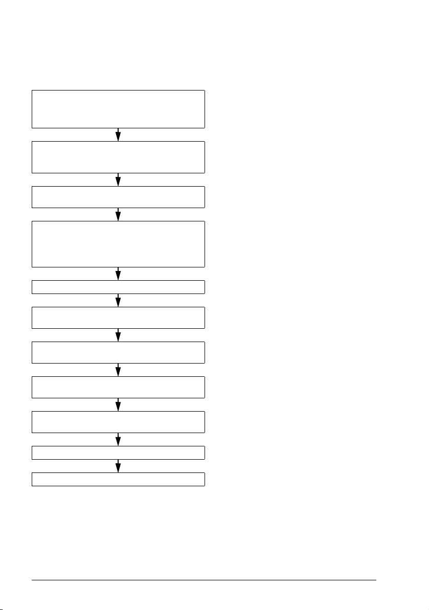
Quick installation and commissioning flowchart
Tas k Se e
Identify the frame size of your drive: R0…R4. Operation principle and hardware description:
Type designation key on page 27
Tec h n i c a l d a ta : Ratings on page 384 or in
section Definitions on page 385
Plan the installation: select the cables, etc.
Check the ambient conditions, ratings and
required cooling air flow.
Unpack and check the drive. Mechanical installation: Checking the delivery
If the drive will be connected to an IT
(ungrounded) or corner grounded system,
check that the internal EMC filter is not
connected.
Install the drive on a wall or in a cabinet. Mechanical installation on page 29
Route the cables. Planning the electrical installation: Rout ing the
Check the insulation of the input cable and the
motor and the motor cable.
Connect the power cables. Electrical installation: Connecting the power
Connect the control cables. Electrical installation: Connecting the control
Planning the electrical installation on page 35
Tec h n i c a l d a ta on page 383
on page 31
Operation principle and hardware description:
Type designation key on page 27
Electrical installation: Checking the
compatibility with IT (ungrounded) and corner
grounded TN systems on page 47
cables on page 41
Electrical installation: Checking the insulation
of the assembly on page 45
cables on page 48
cables on page 50
Check the installation. Installation checklist on page 57
Commission the drive. Start-up on page 59
Page 23

Operation principle and hardware description 23
3
AC motor
M
3~
Rectifier Intermediate
circuit
AC supply
Inverter
Operation principle and hardware description
Contents of this chapter
The chapter briefly describes the operation principle, layout, type designation label
and type designation information. It also shows a general diagram of power
connections and control interfaces.
Operation principle
The ACS320 is a wall or cabinet mountable drive for controlling AC motors.
The figure below shows the simplified main circuit diagram of the drive. The rectifier
converts three-phase AC voltage to DC voltage. The capacitor bank of the
intermediate circuit stabilizes the DC voltage. The inverter converts the DC voltage
back to AC voltage for the AC motor.
Page 24
24 Operation principle and hardware description
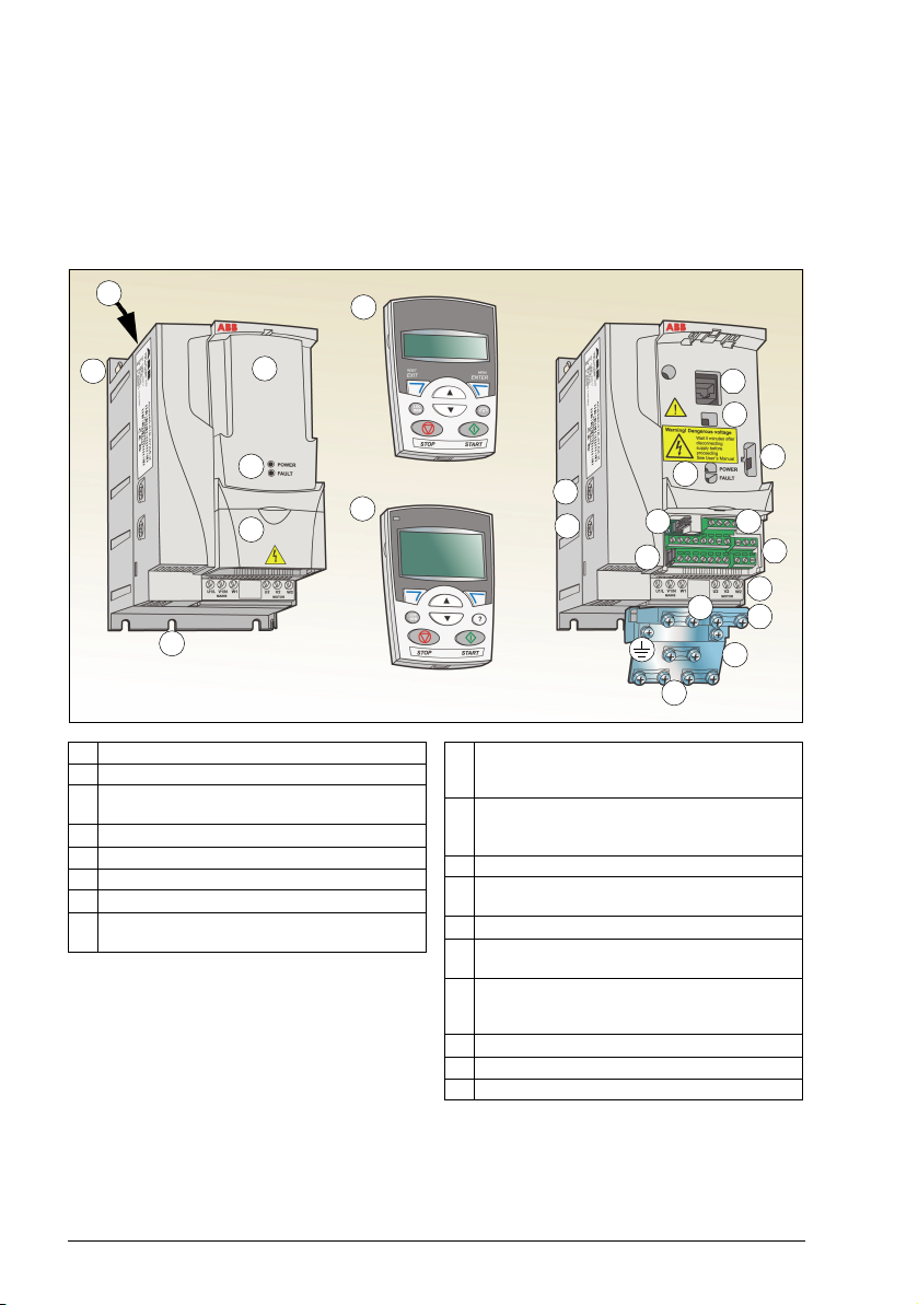
1 Cooling outlet through top cover
2 Mounting holes
3 Panel cover (a) / Basic control panel (b) /
Assistant control panel (c)
4 Terminal cover
5 Panel connection
6 Option connection
7 FlashDrop connection
8 Power OK and Fault LEDs. See section
LEDs on page 381.
9 EMC filter grounding screw (EMC).
Note: The screw is on the front in frame
size R4.
10 Varistor grounding screw (VAR). See
section Protecting the contacts of relay
outputs on page 44.
11 EIA-485 connection
12 Jumper J701 for connecting EIA-485
termination resistor
13 I/O connections
14 Jumper S1 for selecting voltage or current
for analog inputs
15 Input power connection (U1, V1, W1) and
motor connection (U2, V2, W2). (Braking
chopper connection is disabled.)
16 I/O clamping plate
17 Clamping plate
18 Clamps
2
4
3b
3a
3c
5
6
7
8
13
2
11
10
9
8
15
18
18
16
17
1
12
14
Covers on (R2) Covers off (R2)
Product overview
Layout
The layout of the drive is presented below. The figure shows a frame size R2 drive.
The construction of the different frame sizes R0…R4 varies to some extent.
Page 25
Operation principle and hardware description 25
RONO
RONC
3
9
DI1
DI2
DI3
DI4
DI5
+24 V
Aux. voltage output
+24 V DC, max. 200 mA
DOSRC
GND
DCOM
DOOUT
DOGND
Digital/frequency output,
PNP transistor type
30 V DC, max. 100 mA
Relay output
250 V AC / 30 V DC / 6 A
V
mA
GND
+10V
Reference voltage
+10 V DC, max. 10 mA
AI2
Analog input 2
GND
AI1
Analog input 1
0…10 V
SCR
Screen
Analog output
0…20 mA
AI1
AI2
*) Optional, not provided with the drive.
Note: For 1-phase power supply, connect power to U1/L and V1/N terminals.
EMC
VAR
EMC filter grounding screw
Varistor grounding screw
ROCOM
PROGRAMMABLE RELAY
AND DIGITAL OUTPUTS
Output relay
module MREL-01
11 17
18
19
20
21
22
AO 7
GND
8
12
13
14
15
16
10
6
5
1
2
SHIELD
B
A
GND_A
23
24
25
26
PROGRAMMABLE
DIGITAL INPUTS
4
FlashDrop
S1
J701
8
6
6
DI5 can also be used
as a frequency input
L1
L2
L3
PE
U1
V1
W1
PE
Input
choke*
)
EMC
filter*
)
3-phase
power
supply,
200…480
VAC
U2
V2
W2
AC motor
M
3 ~
Output
choke*
)
Control panel (RJ-45)
EFB Comm port
Modbus RTU (EIA-485)
Johnson Controls N2
Siemens Building Technology
FLN (P1), BACnet (MS/TP)
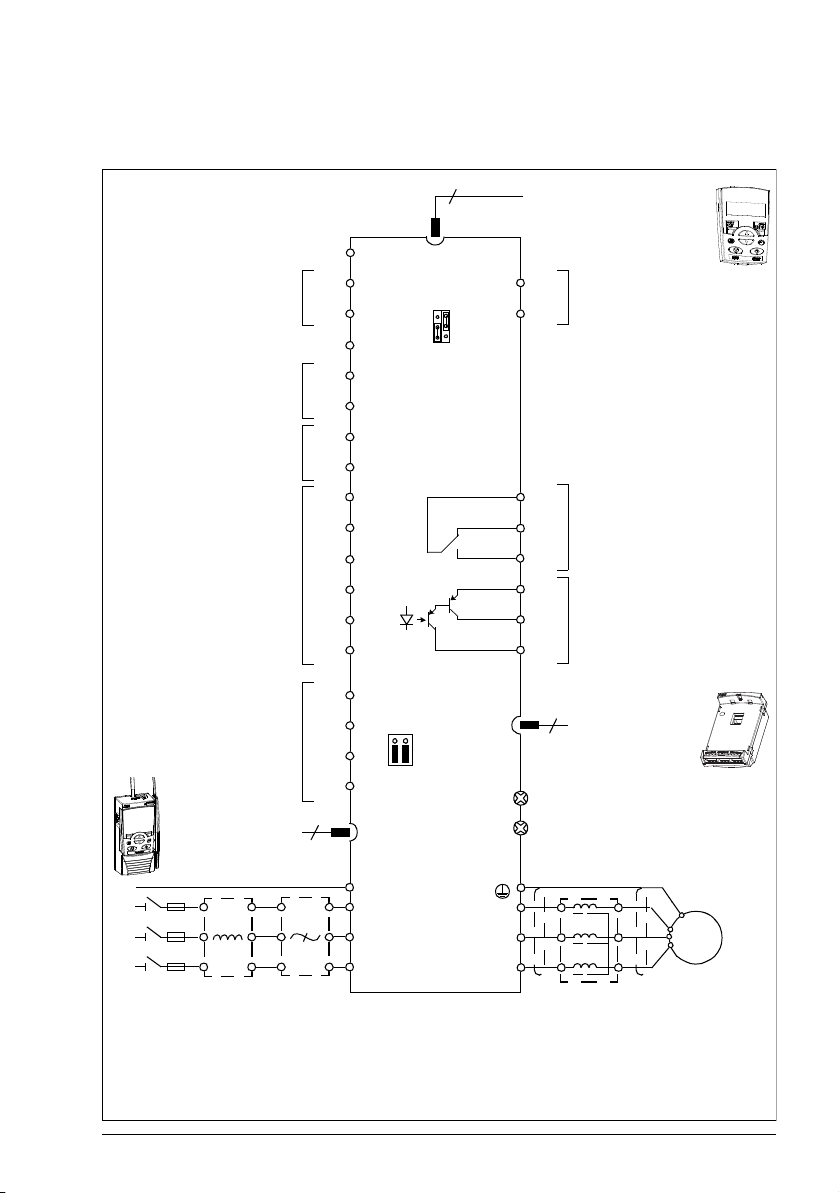
Power connections and control interfaces
The diagram gives an overview of connections. I/O connections are parameterable.
Page 26
26 Operation principle and hardware description
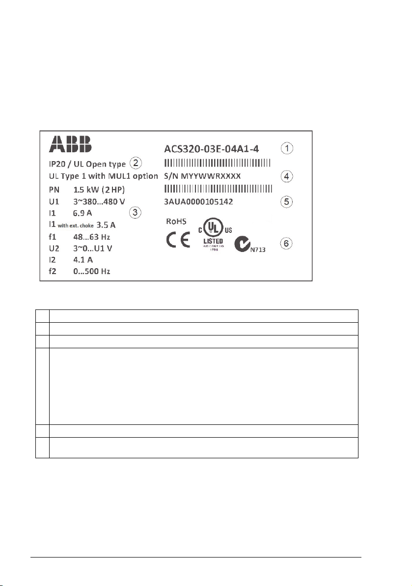
1 Type designation, see section Type designation key on page 27
2 Degree of protection by enclosure (IP and UL/NEMA)
3 Nominal ratings, see section Ratings on page 384 or Definitions on page 385.
4 Serial number of format MYYWWRXXXX, where
M: Manufacturer
YY: 09, 10, 11, … for 2009, 2010, 2011, …
WW: 01, 02, 03, … for week 1, week 2, week 3, …
R: A, B, C, … for product revision number
XXXX: Integer starting every week from 0001
5 ABB MRP code of the drive
6 CE marking and C-Tick, C-UL US and RoHS marks (the label of your drive shows the
valid markings)
See Application macros on page 79 for I/O connections for the different macros and
chapter Electrical installation on page 45 for installation in general.
Type designation label
The type designation label is attached to the left side of the drive. An example label
and explanation of the label contents are shown below.
Page 27
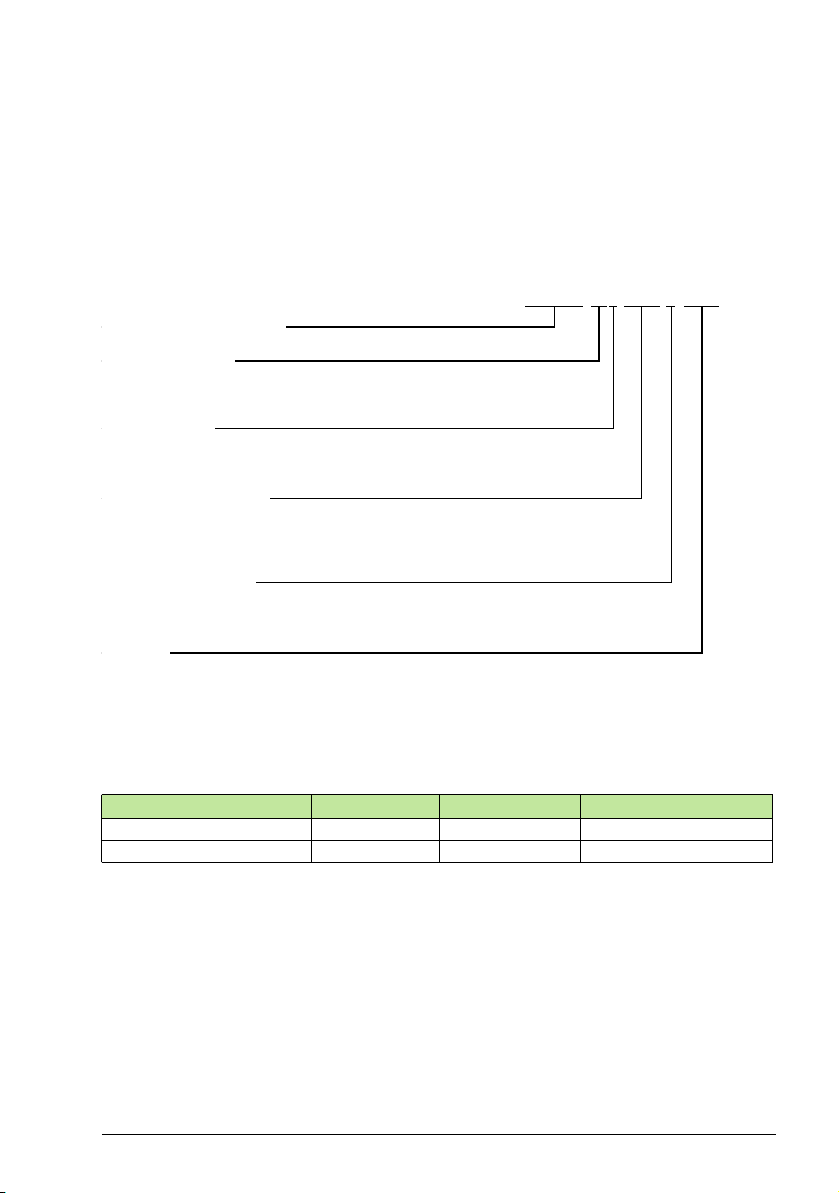
Type designation key
ACS320 product series
01 = 1-phase input
03 = 3-phase input
1-phase/3-phase
In format xxAy, where xx indicates the integer part and y the fractional part,
eg, 08A 8 means 8.8 A. For more information on ratings, types and v oltages, see
sections starting on page 383.
2 = 200 … 240 V AC
4 = 380 … 480 V AC
Input voltage range
E = EMC filter connected, 50 Hz frequency
U = EMC filter disconnected, 60 Hz frequency
1) The ACS320 is compatible with panels that have the following panel revisions and panel firmware
versions.
2) Available for North American market only.
Panel type Typ e c o d e Panel revision Panel firmware version
Basic control panel
2)
ACS-CP-C M or later 1.13 or later
Advanced HVAC control panel ACH-CP-B X or later 2.04 or later
Options
ACS320-03X-08A8-4+J404+...
Output current rating
Configuration
J404 = ACS-CP-C basic control panel
1) 2)
J400 = ACH-CP-B advanced HVAC control panel
1)
R700 = ACS320 user ’s manual in English (3AUA0000062599 [EN])
E202 = RFI filter (available for European market only)
The type designation contains information on the specifications and configuration of
the drive. You find the type designation on the type designation label attached to the
drive. The first digits from the left express the basic configuration, for example
ACS320-03U-09A7-4. The optional selections are given after that, separated by +
signs, for example +J404. The explanations of the type designation selections are
described below.
Operation principle and hardware description 27
Page 28

28 Operation principle and hardware description
Page 29

Mechanical installation 29
4
Mechanical installation
Contents of this chapter
The chapter tells how to check the installation site, unpack, check the delivery and
install the drive mechanically.
Checking the installation site
The drive may be installed on the wall or in a cabinet. Check the enclosure
requirements for the need to use the NEMA 1 option in wall installations (see chapter
Technical data on page 383.
The drive can be installed in three different ways, depending on the frame size:
a) back mounting (all frame sizes)
b) side mounting (frame sizes R0…R2)
c) DIN rail mounting (all frame sizes).
The drive must be installed in an upright position.
Check the installation site according to the requirements below. Refer to chapter
Dimension drawings on page 403 for frame details.
Requirements for the installation site
Operation conditions
See chapter Technical data on page 383 for the allowed operation conditions of the
drive.
Wall
The wall should be as close to vertical and even as possible, of non-flammable
material and strong enough to carry the weight of the drive.
Page 30

30 Mechanical installation
Floor
The floor/material below the installation should be non-flammable.
Free space around the drive
The required free space for cooling above and below the drive is 75 mm (3 in). No
free space is required on the sides of the drive, so drives can be installed side by
side.
Required tools
To install the drive, you need the following tools:
• screwdrivers (as appropriate for the mounting hardware used)
• wire stripper
• tape measure
• drill (if the drive will be installed with screws/bolts)
• mounting hardware: screws or bolts (if the drive will be installed with
screws/bolts). For the number of screws/bolts, see With screws on page 32.
Page 31

Mechanical installation 31
2
1
3
5
4
Unpacking
The drive (1) is delivered in a package that also contains the following items (frame
size R2 shown in the figure):
• plastic bag (2) including clamping plate (also used for I/O cables in frame sizes
R3 and R4), I/O clamping plate (for frame sizes R0…R2), clamps and screws
• panel cover (3)
• mounting template, integrated into the package (4)
• user’s manual (5)
• possible options.
Checking the delivery
Check that there are no signs of damage. Notify the shipper immediately if damaged
components are found.
Before attempting installation and operation, check the information on the type
designation label of the drive to verify that the drive is of the correct type. See section
Type designation label on page 26.
Page 32

32 Mechanical installation
1 22
Installing
The instructions in this manual cover drives with the IP20 degree of protection. To
comply with NEMA 1, use the MUL-R1, MUL-R3 or MUL-R4 option kit, which is
delivered with multilingual installation instructions (3AFE68642868, 3AFE68643147
or 3AUA0000025916, respectively).
Install the drive
Install the drive with screws or on a DIN rail as appropriate.
Note: Make sure that dust from drilling does not enter the drive during the installation.
With screws
1. Mark the hole locations using for example the mounting template cut out from the
package.
The locations of the holes are also shown in the drawings in chapter Dimension
drawings on page 403. The number and location of the holes used depend on
how the drive is installed:
a) back mounting (frame sizes R0…R4): four holes
b) side mounting (frame sizes R0…R2): three holes; one of the bottom holes is
located in the clamping plate.
2. Fix the screws or bolts to the marked locations.
Page 33

Mechanical installation 33
3 4
1 1b
3. Position the drive onto the screws on the wall.
4. Tighten the screws in the wall securely.
On DIN rail
• Click the drive to the rail.
• To detach the drive, press the release lever on top of the drive (1b).
Page 34

34 Mechanical installation
1
2
Fasten clamping plates
1. Fasten the clamping plate to the plate at the bottom of the drive with the provided
screws.
2. For frame sizes R0…R2, fasten the I/O clamping plate to the clamping plate with
the provided screws.
Page 35

Planning the electrical installation 35
5
Planning the electrical installation
Contents of this chapter
The chapter contains the instructions that you must follow when checking the
compatibility of the motor and drive, and selecting cables, protections, cable routing
and way of operation for the drive.
Note: The installation must always be designed and made according to applicable
local laws and regulations. ABB does not assume any liability whatsoever for any
installation which breaches the local laws and/or other regulations. Furthermore, if the
recommendations given by ABB are not followed, the drive may experience problems
that the warranty does not cover.
Implementing the AC power line connection
See the requirements in section Electric power network specification on page 395.
Use a fixed connection to the AC power line.
WARNING! As the leakage current of the device typically exceeds 3.5 mA, a
fixed installation is required according to IEC 61800-5-1.
Page 36

36 Planning the electrical installation
Selecting the supply disconnecting device (disconnecting means)
Install a hand-operated supply disconnecting device (disconnecting means) between
the AC power source and the drive. The disconnecting device must be of a type that
can be locked to the open position for installation and maintenance work.
European union
To meet the European Union Directives, according to standard EN 60204-1, Safety of
Machinery, the disconnecting device must be one of the following types:
• a switch-disconnector of utilization category AC-23B (EN 60947-3)
• a disconnector having an auxiliary contact that in all cases causes switching
devices to break the load circuit before the opening of the main contacts of the
disconnector (EN 60947-3)
• a circuit breaker suitable for isolation in accordance with EN 60947-2.
North America
The ACS320 drive does not include a disconnect device. A means to disconnect
input power must be installed between the AC power source and the ACS320 drive.
This branch circuit protection must:
• be sized to conform to applicable safety regulations, including but not limited to,
both National and local electrical codes.
• be locked in an open position during installation and maintenance work.
The disconnect device must not be used to control the motor. Instead use the control
panel, or commands to the I/O terminals for motor control.
Other regions
The disconnecting device must conform to the applicable safety regulations.
Checking the compatibility of the motor and drive
Check that the 3-phase AC induction motor and the drive are compatible according to
the rating table in section Ratings on page 384 or in section Definitions on page 385.
The table lists the typical motor power for each drive type.
Page 37

Planning the electrical installation 37
Selecting the power cables
General rules
Dimension the input power and motor cables according to local regulations.
• The input power and the motor cables must be able to carry the corresponding
load currents. See section Ratings on page 384 or in section Definitions on page
385 for the rated currents.
• The cable must be rated for at least 70 °C maximum permissible temperature of
the conductor in continuous use. For US, see section Additional North American
requirements on page 39.
• The conductivity of the PE conductor must be equal to that of the phase
conductor (same cross-sectional area).
• 600 V AC cable is accepted for up to 500 V AC.
• Refer to chapter Technical data on page 383 for the EMC requirements.
A symmetrical shielded motor cable (see the figure below) must be used to meet the
EMC requirements of the CE and C-Tick marks.
A four-conductor system is allowed for input cabling, but a shielded symmetrical
cable is recommended.
Compared to a four-conductor system, the use of a symmetrical shielded cable
reduces electromagnetic emission of the whole drive system as well as motor bearing
currents and wear.
Page 38

38 Planning the electrical installation
Symmetrical shielded cable: three phase
conductors, a concentric or otherwise
symmetrically constructed PE conductor
and a shield
Motor cables
(recommended for input cables also)
PE
conductor
and shield
Shield
Shield
PE
PE
Allowed as input cables
A four-conductor system: three phase
conductors and a protective conductor
Note: A separate PE conductor is required
if the conductivity of the cable shield is not
sufficient for the purpose.
Shield
PEPE
Insulation jacket Copper wire screen Cable core
Alternative power cable types
Power cable types that can be used with the drive are presented below.
Motor cable shield
To function as a protective conductor, the shield must have the same cross-sectional
area as the phase conductors when they are made of the same metal.
To effectively suppress radiated and conducted radio-frequency emissions, the shield
conductivity must be at least 1/10 of the phase conductor conductivity. The
requirements are easily met with a copper or aluminium shield. The minimum
requirement of the motor cable shield of the drive is shown below. It consists of a
concentric layer of copper wires. The better and tighter the shield, the lower the
emission level and bearing currents.
Page 39

Planning the electrical installation 39
Additional North American requirements
Type MC continuous corrugated aluminium armor cable with symmetrical grounds or
shielded power cable is recommended for the motor cables if metallic conduit is not
used.
The power cables must be rated for 75 °C (167 °F).
Conduit
Where conduits must be coupled together, bridge the joint with a ground conductor
bonded to the conduit on each side of the joint. Bond the conduits also to the drive
enclosure. Use separate conduits for input power, motor and control wiring. Do not
run motor wiring from more than one drive in the same conduit.
Armored cable / shielded power cable
Six-conductor (three phases and three ground) type MC continuous corrugated
aluminium armor cable with symmetrical grounds is available from the following
suppliers (trade names in parentheses):
• Anixter Wire & Cable (Philsheath)
• BICC General Corp (Philsheath)
• Rockbestos Co. (Gardex)
• Oaknite (CLX).
Shielded power cable is available from the following suppliers:
•Belden
• LAPPKABEL (ÖLFLEX)
• Pirelli.
Page 40

40 Planning the electrical installation
Double-shielded twisted
multipair cable
Single-shielded twisted
multipair cable
a b
Selecting the control cables
General rules
All analog control cables and the cable used for the frequency input must be shielded.
Use a double-shielded twisted pair cable (figure a, for example JAMAK by Draka NK
Cables) for analog signals. Employ one individually shielded pair for each signal. Do
not use common return for different analog signals.
A double-shielded cable is the best alternative for low-voltage digital signals, but a
single-shielded or unshielded twisted multipair cable (figure b) is also usable.
However, for frequency input, always use a shielded cable.
Run analog and digital signals in separate cables.
Relay-controlled signals, providing their voltage does not exceed 48 V, can be run in
the same cables as digital input signals. It is recommended that the relay-controlled
signals are run as twisted pairs.
Never mix 24 V DC and 115/230 V AC signals in the same cable.
Relay cable
The cable type with braided metallic screen (for example ÖLFLEX by LAPPKABEL)
has been tested and approved by ABB.
Control panel cable
In remote use, the cable connecting the control panel to the drive must not exceed
3 m (10 ft). The cable type tested and approved by ABB is used in control panel
option kits.
Page 41

Planning the electrical installation 41
Drive
Motor cable
Power cable
min. 300 mm (12 in)
Motor cable
min. 200 mm (8 in)
Input power cable
Control cables
90°
min. 500 mm (20 in)
Lead 24 V and 230 V control cables in
separate ducts inside the cabinet.
Not allowed unless the 24 V cable is
insulated for 230 V or insulated with an
insulation sleeving for 230 V.
230 V24 V 230 V24 V
Routing the cables
Route the motor cable away from other cable routes. Motor cables of several drives
can be run in parallel installed next to each other. It is recommended that the motor
cable, input power cable and control cables are installed on separate trays. Avoid
long parallel runs of motor cables with other cables to decrease electromagnetic
interference caused by the rapid changes in the drive output voltage.
Where control cables must cross power cables make sure that they are arranged at
an angle as near to 90 degrees as possible.
The cable trays must have good electrical bonding to each other and to the grounding
electrodes. Aluminium tray systems can be used to improve local equalizing of
potential.
A diagram of the cable routing is shown below.
Control cable ducts
Page 42

42 Planning the electrical installation
M
3~
Distribution
board
Input cable Drive
1)
Protecting the drive, input power cable, motor and motor cable in short circuit situations and against thermal overload
Protecting the drive and input power cable in short-circuit situations
Arrange the protection according to the following guidelines.
Circuit diagram Short-circuit protection
Protect the drive and input
cable with fuses or ABB
manual motor starter.
Size the fuses according to instructions given in chapter Technical data on page 383.
The fuses will protect the input cable in short-circuit situations, restrict drive damage
and prevent damage to adjoining equipment in case of a short-circuit inside the drive.
Protecting the motor and motor cable in short-circuit situations
The drive protects the motor and motor cable in a short-circuit situation when the
motor cable is dimensioned according to the nominal current of the drive. No
additional protection devices are needed.
Protecting the motor against thermal overload
According to regulations, the motor must be protected against thermal overload and
the current must be switched off when overload is detected. The drive includes a
motor thermal protection function that protects the motor and switches off the current
when necessary. It is also possible to connect a motor temperature measurement to
the drive. The user can tune both the thermal model and the temperature
measurement function further by parameters.
The most common temperature sensors are:
• motor sizes IEC180…225: thermal switch (for example Klixon)
• motor sizes IEC200…250 and larger: PTC or Pt100.
For more information on the thermal model, see section Motor thermal protection on
page 118. For more information on the temperature measurement function see
section Motor temperature measurement through the standard I/O on page 127.
Page 43

Planning the electrical installation 43
Using residual current devices (RCD) with the drive
ACS320-03x drives are suitable to be used with residual current devices of Type B.
Other measures for protection in case of direct or indirect contact, such as separation
from the environment by double or reinforced insulation or isolation from the supply
system by a transformer, can also be applied.
Implementing a bypass connection
WARNING! Never connect the supply power to the drive output terminals U2,
V2 and W2. Power line voltage applied to the output can result in permanent
damage to the drive.
If frequent bypassing is required, employ mechanically connected switches or
contactors to ensure that the motor terminals are not connected to the AC power line
and drive output terminals simultaneously.
Page 44

44 Planning the electrical installation
Drive
relay
output
Drive
relay
output
Drive
relay
output
Var istor
RC filter
Diode
230 V AC
24 V DC
230 V AC
Protecting the contacts of relay outputs
Inductive loads (relays, contactors, motors) cause voltage transients when switched
off.
Equip inductive loads with noise attenuating circuits (varistors, RC filters [AC] or
diodes [DC]) in order to minimize the EMC emission at switch-off. If not suppressed,
the disturbances may connect capacitively or inductively to other conductors in the
control cable and form a risk of malfunction in other parts of the system.
Install the protective component as close to the inductive load as possible. Do not
install protective components at the I/O terminal block.
Page 45

Electrical installation 45
6
Electrical installation
Contents of this chapter
The chapter tells how to check the insulation of the assembly and the compatibility
with IT (ungrounded) and corner grounded TN systems as well as connect power
cables, control cables and embedded fieldbus.
WARNING! Obey the safety instructions. See chapter Safety on page 15. If
you ignore the safety instructions, injury or death can occur. If you are not a
qualified electrician, do not do electrical work.
Make sure that the drive is disconnected from the input power during installation. If
the drive is already connected to the input power, wait for 5 minutes after
disconnecting the input power.
Checking the insulation of the assembly
Drive
Do not make any voltage tolerance or insulation resistance tests (for example hi-pot
or megger) on any part of the drive as testing can damage the drive. Every drive has
been tested for insulation between the main circuit and the chassis at the factory.
Also, there are voltage-limiting circuits inside the drive which cut down the testing
voltage automatically.
Input power cable
Check the insulation of the input power cable according to local regulations before
connecting to the drive.
Page 46

46 Electrical installation
ohm
M
3~
U1
V1
W1
PE
500 V DC,
≥ 10 Mohm
U1-V1, U1-W1, V1-W1
U1-PE, V1-PE, W1-PE
Motor and motor cable
Check the insulation of the motor and motor cable as follows:
1. Check that the motor cable is disconnected from the drive output terminals T1/U,
T2/V and T3/W.
2. Measure the insulation resistance between the phase conductors and between
each phase conductor and the Protective Earth (PE) conductor. Use a measuring
voltage of 500 V DC. The insulation resistance of a motor must exceed 10 Mohm
(reference value at 25 °C or 77 °F). For the insulation resistance of other motors,
consult the manufacturer’s instructions.
Note: Moisture inside the motor casing reduces the insulation resistance. If
moisture is suspected, dry the motor and repeat the measurement.
Page 47

Electrical installation 47
Note: In frame size R4
the EMC screw is located
to the right of terminal W2.
1
EMC
VA R
1
EMC
Checking the compatibility with IT (ungrounded) and corner grounded TN systems
WARNING! Disconnect the internal EMC filter when installing the drive on an
IT system (an ungrounded power system or a high resistance-grounded [over
30 ohms] power system), otherwise the system will be connected to ground potential
through the EMC filter capacitors. This may cause danger or damage the drive.
Disconnect the internal EMC filter when installing the drive on a corner-grounded TN
system, otherwise the drive will be damaged.
Note: When the internal EMC filter is disconnected, the drive is not EMC compatible
without an external filter.
1. If you have an IT (ungrounded) or corner grounded TN system, disconnect the
internal EMC filter by removing the EMC screw. For 3-phase U-type drives (with
type designation ACS320-03U-), the EMC screw is already removed at the factory
and replaced by a plastic one.
Pay attention to the screws! Do not confuse the EMC screw to the similar varistor
disconnecting screw. Do not disconnect the varistor. The varistor protects the
drive against power line voltage peaks.
Page 48

48 Electrical installation
U2 V2 W2
INPUT
1)
Drive
For alternatives, see section
Selecting the supply
disconnecting device
(disconnecting means) on
page 36.
OUTPUT
U1 V1 W1
Motor
3 ~
V1
U1 W1
PE
PE
L1 L2 L3
1. Ground the other end of the PE conductor at the distribution board.
2. Use a separate grounding cable if the conductivity of the cable shield is insufficient
(smaller than the conductivity of the phase conductor) and there is no symmetrically
constructed grounding conductor in the cable. See section Selecting the power cables on
page 37.
3. L and N are connection markings for the 1-phase power supply.
2)
(L) (N)
3)
ab
b > 1/5 · a
Connecting the power cables
Connection diagram
Notes:
• Do not use an asymmetrically constructed motor cable.
• If there is a symmetrically constructed grounding conductor in the motor cable in
addition to the conductive shield, connect the grounding conductor to the
grounding terminal at the drive and motor ends.
• Route the motor cable, input power cable and control cables separately. For more
information, see section Routing the cables on page 41.
Grounding of the motor cable shield at the motor end
For minimum radio frequency interference:
• ground the cable by twisting the shield as
follows: flattened width >
• or ground the cable shield 360 degrees at the
lead-through of the motor terminal box.
1/5 · length
Page 49

Electrical installation 49
1
1
2
2
2
Connection procedure
1. Fasten the grounding conductor (PE) of the input power cable under the
grounding clamp. Connect the phase conductors to the U1, V1 and W1 terminals.
Use a tightening torque of 0.8 N·m (7 in-lb) for frame sizes R0…R2, 1.7 N·m
(15 in-lb) for R3, and 2.5 N·m (22 in-lb) for R4.
2. Strip the motor cable and twist the shield to form as short a pigtail as possible.
Fasten the twisted shield under the grounding clamp. Connect the phase
conductors to the U2, V2 and W2 terminals. Use a tightening torque of 0.8 N·m
(7 in-lb) for frame sizes R0…R2, 1.7 N·m (15 in-lb) for R3, and 2.5 N·m (22 in-lb)
for R4.
3. Secure the cables outside the drive mechanically.
Page 50

50 Electrical installation
X1A:
1: SCR
2: AI1
3: GND
4: +10 V
5: AI2
6: GND
7: AO
8: GND
9: +24 V
10: GND
11: DCOM
12: DI1
13: DI2
14: DI3
15: DI4
16: DI5 digital or frequency input
X1B:
17: ROCOM
18: RONC
19: RONO
20: DOSRC
21: DOOUT
22: DOGND
X1C:
23: SCR
24: B
25: A
26: GND_A
mA
V
S1
X1A X1B
X1CJ701
AI1
AI2
J701: Connects 120 ohm termination resistor. See page
55.
S1: Selects voltage or current as the signal types for
analog inputs AI1 and AI2.
AI1
AI2
Top position: I (0 [4]…20 mA, default for AI2; or -20…20 mA)
Bottom position: U (0 [2]…10 V, default for AI1; or -10…10 V)
S1
Connecting the control cables
I/O terminals
The figure below shows the I/O terminals. Tightening torque is 0.4 N·m / 3.5 in-lb.
WAR N ING ! All ELV (Extra Low Voltage) circuits connected to the drive must be
used within a zone of equipotential bonding, in other words, within a zone
where all simultaneously accessible conductive parts are electrically connected to
prevent hazardous voltages appearing between them. This is accomplished by a
proper factory grounding.
The terminals on the control board as well as on the optional modules attachable to
the board fulfill the Protective Extra Low Voltage (PELV) requirements stated in EN
50178, provided that the external circuits connected to the terminals also fulfill the
requirements and the installation site is below 2000 m (6562 ft).
Voltage and current selection for analog inputs
Jumper S1 selects voltage (0 [2]…10 V / -10…10 V) or current (0 [4]…20 mA /
-20…20 mA) as the signal types for analog inputs AI1 and AI2. The factory settings
are unipolar voltage for AI1 (0 [2]…10 V) and unipolar current for AI2 (0 [4]…20 mA),
which correspond to the default usage in the application macros. The jumper is
located to the left of I/O terminal 9 (see the I/O terminal figure above).
Permanently affix control cables with a minimum 1/4" spacing from power cables.
Page 51

Electrical installation 51
SCR
AI
+10V
1…10 kohm
Unipolar voltage
+10 V GND -10 V
Bipolar voltage Unipolar/Bipolar current
Use external power supply.
GND
SCR
AI
GND
SCR
AI
GND
9 +24V
10 GND
11 DCOM
12 DI1
13 DI2
14 DI3
15 DI4
16 DI5
9 +24V
10 GND
11 DCOM
12 DI1
13 DI2
14 DI3
15 DI4
16 DI5
X1X1
NPN connection (sink)PNP connection (source)
NPN connection (sink)PNP connection (source)
9 +24V
10 GND
11 DCOM
12 DI1
13 DI2
14 DI3
15 DI4
16 DI5
9+24V
10 GND
11 DCOM
12 DI1
13 DI2
14 DI3
15 DI4
16 DI5
X1X1
+24 V DC
0VDC
0VDC
+24 V DC
Voltage and current connection for analog inputs
Bipolar voltage (-10…10 V) and current (-20…20 mA) are also possible. If a bipolar
connection is used instead of a unipolar one, see section Programmable analog
inputs on page 107 for how to set parameters accordingly.
PNP and NPN configuration for digital inputs
You can wire the digital input terminals in either a PNP or NPN configuration.
External power supply for digital inputs
For using an external +24 V supply for the digital inputs, see the figure below.
Page 52

52 Electrical installation
X1A
5 AI2 Process actual value measurement or reference,
4…20 mA, R
in
= 100 ohm
6GND
…
9 +24V Auxiliary voltage output, non-isolated,
+24 V DC, max. 200 mA
10 GND
P
I
4…20 mA
Frequency input
If DI5 is used as a frequency input, see section Frequency input on page 111 for how
to set parameters accordingly.
Connection example of a two-wire sensor
HVAC default, supply fan, return fan, cooling tower fan, condenser, booster pumps,
PFA control, internal timer, dual setpoint with PID, E-Clipse and dual setpoint with PID
and constant speeds macros (see section Application macros on page 79) use
analog input 2 (AI2). The macro wiring diagrams for these macros show the
connection when a separately powered sensor is used. The figure below gives an
example of a connection using a two-wire sensor.
Note: The sensor is supplied through its current output. Thus the output signal must
be 4…20 mA.
Page 53

Electrical installation 53
X1A
1 SCR Signal cable shield (screen)
2AI1 External reference: 0…10 V or 0...20 mA
3 GND Analog input circuit common
4 +10V Reference voltage: +10 V DC, max. 10 mA
5 AI2 PID feedback 0…10 V or 0...20 mA
6 GND Analog input circuit common
7AO Output frequency value: 0…20 mA
8 GND Analog output circuit common
9 +24V Auxiliary voltage output: +24 V DC, max. 200 mA
10 GND Auxiliary voltage output common
11 DCOM Digital input common
12 DI1 Stop (0) / Start (1)
13 DI2 Not Configured
14 DI3 Constant speed selection
1)
15 DI4 Safety Interlock
16 DI5 Not Configured
X1B
17 ROCOM Relay output 1
Default operation: Ready
18 RONC
19 RONO
20 DOSRC Digital output, max. 100 mA
No fault [Fault (-1)]
21 DOOUT
22 DOGND
max. 500 ohm
1…10 kohm
Tightening torque: 0.4 N·m (3.5 lbf·in).
DI3 Operation (parameter)
0 Set speed through AI1
1 Speed 1 (1202)
0 Speed 2 (1203)
1 Speed 3 (1204)
Default I/O connection diagram
The default connection of the control signals depends on the application macro in
use, which is selected with parameter 9902 APPLIC MACRO.
The default macro is the HVAC Default. It provides a general purpose I/O
configuration with three constant speeds. Parameter values are the default values
given in section Parameters in the short parameter view on page 144. For information
on other macros, see section Application macros on page 79.
The default I/O connections for the ABB standard macro are given in the figure below.
Page 54

54 Electrical installation
2
4
3
4
2
1
5
7
4
5
6
7
9
Connection procedure
1. Remove the terminal cover by simultaneously pushing the recess and sliding the
cover off the frame.
2. Digital signals: Strip the outer insulation of the digital signal cable 360 degrees
and ground the bare shield under the clamp.
3. Connect the conductors of the cable to the appropriate terminals. Use a tightening
torque of 0.4 N·m (3.5 in-lb).
4. For double-shielded cables, twist also the grounding conductors of each pair in
the cable together and connect the bundle to the SCR terminal (terminal 1).
5. Analog signals: Strip the outer insulation of the analog signal cable 360 degrees
and ground the bare shield under the clamp.
6. Connect the conductors to the appropriate terminals. Use a tightening torque of
0.4 N·m (3.5 in-lb).
7. Twist the grounding conductors of each pair in the analog signal cable together
and connect the bundle to the SCR terminal (terminal 1).
8. Secure all cables outside the drive mechanically.
9. Slide the terminal cover back in place.
Page 55

Electrical installation 55
X1C
23 SCR Fieldbus cable shield (screen)
24 B Positive
25 A Negative
26 GND_A Fieldbus common
SCR
+
-
GND
SCR GND_AABJ701
X1C
J701
Fieldbus
Fieldbus
controller
Jumper shunts
connect the
120 ohm
termination
resistor.
J701J701
EIA-485
RS-232
Fieldbus
controller
<3m
Connecting the embedded fieldbus
Embedded fieldbus can be connected to the drive with EIA-485 or RS-232.
Connection diagram
EIA-485
The figure below shows the fieldbus connection.
Terminate the EIA-485 bus with a 120 ohm resistor at the end of the network by
setting the jumper J701 shunts as in the figure below.
RS-232
Plug a communication cable into the control panel connection X2. The cable must be
shorter than 3 meters.
Page 56

56 Electrical installation
Page 57

Installation checklist 57
7
Installation checklist
Contents of this chapter
This chapter contains the task list to be followed after the mechanical and electrical
installation before proceeding to starting up the drive.
Checking the installation
Check the mechanical and electrical installation of the drive before start-up. Go
through the checklist below together with another person. Read chapter Safety on
page 15 of this manual before you work on the drive.
Check
MECHANICAL INSTALLATION
The ambient operating conditions are allowed. (See Mechanical installation: C hecking the
installation site on page 29 as well as Technical data: Losses, cooling data and noise on
page 393 and Ambient conditions on page 397.)
The drive is fixed properly on an even vertical non-flammable wall. (See Mechanical
installation on page 29.)
The cooling air will flow freely. (See Mechanical installation: Free space around the drive
on page 30.)
The motor and the driven equipment are ready for start. (See Planning the electrical
installation: Checking the compatibility of the motor and drive on page 36 as well as
Technical data: Motor connection data on page 395.)
ELECTRICAL INSTALLATION (See Planning the electrical installation on page 35 and
Electrical installation on page 45.)
For ungrounded and corner grounded systems: The internal EMC filter is disconnected
(EMC screw removed).
The capacitors are reformed if the drive has been stored over a year.
The drive is grounded properly.
The input power voltage matches the drive nominal input voltage.
Page 58

58 Installation checklist
Check
The input power connections at U1, V1 and W1 are OK and tightened with the correct
torque.
Appropriate input power fuses and disconnector are installed.
The motor connections at U2, V2 and W2 are OK and tightened with the correct torque.
The motor cable, input power cable and control cables are routed separately.
Use wire ties to permanently affix control/communications wiring to the clamps provided
to maintain a minimum 1/4" spacing from power wiring.
The external control (I/O) connections are OK.
The input power voltage cannot be applied to the output of the drive (with a bypass
connection).
Terminal cover and, for NEMA 1, hood and connection box, are in place.
Page 59

Start-up 59
8
1
2
3
4
5
7
8
9
6
1 Status LED (Green when normal, if flashing or
red, see section LEDs on page 381.)
2 Soft key 1
3Auto
4Off
5Up
6Down
7 Soft key 2
8 Help (always available)
9Hand
Start-up
Contents of this chapter
This chapter contains a brief description of the assistant (HVAC) control panel
(operator keypad), start-up assistant and application selection.
This chapter also includes the application macros used for defining a group of
parameters. Macros change a group of parameters to new, predefined values. Use
macros to minimize the need for manual editing of parameters.
HVAC control panel features
The ACS320 HVAC control panel (ACH-CP-B) features:
Page 60

60 Start-up
• Language selection for the display
• Drive connection that can be made or detached at any time
• Start-up assistant to facilitate drive commissioning
• Copy function for moving parameters to other ACS320 drives
• Backup function for saving parameter sets
• Context sensitive help
• Real-time clock
General display features
Soft key functions
The soft key functions are defined by text displayed just above each key.
Display contrast
To adjust display contrast, simultaneously press and or , as
appropriate.
Macros
Note: Selecting the appropriate macro should be part of the original system design,
since the control wiring installed depends on the macro used.
1. Review the macro descriptions in section Application macros on page 79. Use the
macro that best fits system needs.
2. Edit parameter 9902 APPLIC MACRO to select the appropriate macro. Use either
of the following:
• Use the Start-up assistant, which displays the macro selection immediately
after motor parameter setup.
• Refer to section Parameters mode on page 66 for parameter editing
instructions.
Turning - parameters
The system can benefit from one or more of the ACS320 special features, and/or fine
tuning.
1. Review the parameter descriptions in section Parameter listing starting on
page 148. Enable options and fine tune parameter values as appropriate for the
system.
2. Edit parameters as appropriate.
Page 61

Start-up 61
Fault and alarm adjustments
The drive can detect a wide variety of potential system problems. For example, initial
system operation may generate faults of alarms that indicate set-up problems.
1. Faults and alarms are reported on the control panel with a number. Note the
number reported.
2. Review the description provided for the reported fault/alarm:
• Use the fault and alarm listings shown in chapter Fault tracing on 359.
• Press the help key (Assistant control panel only) while fault or alarm is
displayed.
3. Adjust the system or parameters as appropriate.
Page 62

62 Start-up
Do you want to
use the start-up
assistant?
Yes
No
EXIT
OK
CHOICE 2OFF
0 A
0 %
0 mA0.
0.
0.
0.0HzOFF
MENU
SP
PARAMETERS
ASSISTANTS
CHANGED PAR
EXIT ENTER
OFF MAIN MENU 2
Spin the motor
Commission drive
References 1 & 2
Start/Stop Control
Protections
EXIT
SEL
ASSISTANTS 2OFF
9901 LANGUAGE
PAR EDIT
ENGLISH
[0]
OFF
EXIT SAVE
Start-up
Start-up can be performed in two ways:
• Using the Start-up assistant.
See section Start-up by using the Start-up assistant.
• Changing the parameters individually.
See section Start-up by changing the parameters individually.
Start-up by using the Start-up assistant
To start the Start-up assistant, follow these steps:
Select MENU to enter the main
menu
1
Select ASSISTANTS with the
Up/Down buttons and select
ENTER.
2
Scroll to Commission drive with
the Up/Down buttons.
3
Change the values suggested by
the assistant to your preferences
and then press SAVE after every
4
change.
The Start-up assistant will guide you through the start-up.
Page 63

Start-up by changing the parameters individually
0 A
0 %
0 mA0.
0.
0.
0.0Hz
OFF
MENU
SP
PARAMETERS
ASSISTANTS
CHANGED PAR
EXIT ENTER
1OFF MAIN MENU
99 START-UP DATA
01 OPERATING DATA
03 FB ACTUAL SIGNALS
04 FAULT HISTORY
10 START/STOP/DIR
PAR GROUPS 99
EXIT
SEL
OFF
9901 LANGUAGE
9902 APPLIC MACRO
HVAC DEFAULT
9905 MOTOR NOM VOLT
9906 MOTOR NOM CURR
PARAMETERS
EXIT
EDIT
OFF
9902 APPLIC MACRO
PAR EDIT
HVAC DEFAULT
[1]
OFF
CANCEL SAVE
9902 APPLIC MACRO
PAR EDIT
SUPPLY FAN
[2]
OFF
CANCEL SAVE
9901 LANGUAGE
9902 APPLIC MACRO
SUPPLY FAN
9905 MOTOR NOM VOLT
9906 MOTOR NOM CURR
PARAMETERS
EXIT
EDIT
OFF
To change the parameters, follow these steps:
Select MENU to enter the main
menu.
1
Select PARAMETERS with the
UP/DOWN buttons and select
ENTER to select the Parameters
mode.
2
Select the appropriate parameter
group with the UP/DOWN
buttons and select SEL
3
Select the appropriate parameter
with the UP/DOWN buttons.
Select EDIT to change the
parameter value.
4
Start-up 63
Press the UP/DOWN buttons to
change the parameter value.
5
Select SAVE to store the
modified value or select
CANCEL to leave the set mode.
6
Any modifications not saved are
canceled.
Select EXIT to return to the
listing of parameter groups, and
again to return to the main menu.
7
To complete the control connections by manually entering the parameters, see
section Parameters mode on page 66.
For detailed hardware description, see the chapter Technical data.
Page 64

64 Start-up
Notes:
• The current parameter value appears below the highlighted parameter.
• To view the default parameter value, press the UP/DOWN buttons simultaneously.
• The most typical and necessary parameters to change belong to Group 99: Start-
up data, Group 10: Start/Stop/Dir, Group 11: Reference select, Group 20: Limits,
Group 21: Start/Stop, Group 22: Accel/Decel, Group 30: Fault functions, Group
53: EFB protocol and Group 98: Options.
• To restore the default factory settings, select the application macro HVAC default.
Modes
The HVAC control panel has several different modes for configuring, operating and
diagnosing the drive. The modes are:
• Standard display mode – Shows drive status information and operates the drive.
• Parameters mode – Edits parameter values individually.
• Start-up assistant mode – Guides the start-up and configuration.
• Changed parameters mode – Shows changed parameters.
• Fault logger mode – Shows the drive fault history.
• Drive parameter backup mode – Stores or uploads the parameters.
• Clock set mode – Sets the time and date for the drive.
• I/O settings mode – Checks and edits the I/O settings.
• Alarm mode – Reporting mode triggered by drive alarms.
Standard display mode
Use the standard display mode to read information on the drive’s status and to
operate the drive. To reach the standard display mode, press EXIT until the LCD
display shows status information as described below.
Page 65

Start-up 65
7 A
0 %
8 mA8.
3.
30.
15.0HzAUTO
MENU00:00
7 A
0 %
3.
30.
15.0Hz
AUTO
MENU00:00
mA 44%
Status information
Top. The top line of the LCD display shows the basic status information of the drive.
•HAND – Indicates that the drive control is local, that is, from the control panel.
•AUTO – Indicates that the drive control is remote, such as the basic I/O (X1) or
fieldbus.
• OFF – Indicates that the drive control is local and stopped.
• – Indicates the drive and motor rotation status as follows:
Control panel display Significance
Rotating arrow (clockwise or
counterclockwise)
Rotating dotted arrow blinking Drive is running but not at setpoint
Stationary dotted arrow Start command is present, but motor is not running.
• Upper right – shows the active reference.
Middle. Using Group 34: Panel display, the middle of the
LCD display can be configured to display:
• One to three parameter values – The default display
shows parameters 0103 OUTPUT FREQ in
percentages, 0104 CURRENT in amperes and 0120
AI1 in milliamperes.
- Use parameters 3401, 3408, and 3415 to select the parameters (from Group
01: Operating data) to display. Entering “parameter” 0100 results in no
parameter displayed. For example, if 3401 = 0100 and 3415 = 0100, then only
the parameter specified by 3408 appears in the Control panel display.
- You can also scale each parameter in the display, for example, to convert the
motor speed to a display of conveyor speed. Parameters 3402…3405 scale the
parameter specified by 3401, parameters 3409…3412 scale the parameter
specified by 3408, etc.
• A bar meter rather than one of the parameter values.
- Enable bar graph displays using parameters 3404,
3411 and 3418.
Bottom. The bottom of the LCD display shows:
• Lower corners – show the functions currently
assigned to the two soft keys.
• Lower middle – displays the current time (if configured to show the time).
• Drive is running and at setpoint
• Shaft direction is forward or reverse
For example, start enable is missing.
Page 66

66 Start-up
0 A
0 %
0 mA0.
0.
0.
0.0HzOFF
MENU
SP
PARAMETERS
ASSISTANTS
CHANGED PAR
EXIT ENTER
1
OFF
MAIN MENU
99 START-UP DATA
01 OPERATING DATA
03 FB ACTUAL SIGNALS
04 FAULT HISTORY
10 START/STOP/DIR
PAR GROUPS 99
EXIT
SEL
OFF
Operating the drive
AUTO/HAND – The very first time the drive is powered up, it is in the auto control
(AUTO) mode, and is controlled from the Control terminal block X1.
To switch to hand control (HAND) and control the drive using the control panel, press
and hold the or button.
• Pressing the HAND button switches the drive to hand control while keeping the
drive running.
• Pressing the OFF button switches to hand control and stops the drive.
To switch back to auto control (AUTO), press and hold the button.
Hand/Auto/Off – To start the drive press the HAND or AUTO buttons, to stop the
drive press the OFF button.
Reference – To modify the reference (only possible if the display in the upper right
corner is in reverse video) press the UP or DOWN buttons (the reference changes
immediately).
The reference can be modified in the local control mode, and can be parameterized
(using Group 11: Reference select) to also allow modification in the remote control
mode.
Note: The Start/Stop, Shaft direction and Reference functions are only valid in local
control (LOC) mode.
Parameters mode
To change the parameters, follow these steps:
Select MENU to enter the main
menu.
1
Select PARAMETERS with the
UP/DOWN buttons, and select
ENTER to select the Parameters
mode.
2
Select the appropriate parameter
group with the UP/DOWN
buttons and select SEL
3
Page 67

Select the appropriate parameter
9901 LANGUAGE
9902 APPLIC MACRO
HVAC DEFAULT
9905 MOTOR NOM VOLT
9906 MOTOR NOM CURR
PARAMETERS
EXIT
EDIT
OFF
9902 APPLIC MACRO
PAR EDIT
HVAC DEFAULT
[1]
OFF
CANCEL SAVE
9902 APPLIC MACRO
PAR EDIT
SUPPLY FAN
[2]
OFF
CANCEL SAVE
9901 LANGUAGE
9902 APPLIC MACRO
SUPPLY FAN
9905 MOTOR NOM VOLT
9906 MOTOR NOM CURR
PARAMETERS
EXIT
EDIT
OFF
in a group with the UP/DOWN
buttons. Select EDIT to change
the parameter.
4
Press the UP/DOWN buttons to
change the parameter value.
5
Select SAVE to store the
modified value or select
CANCEL to leave the set mode.
• Any modifications not saved
6
are canceled.
• Each individual parameter
setting is valid immediately
after pressing SAVE.
Select EXIT to return to the
listing of parameter groups, and
again to return to the main menu.
7
Start-up 67
To complete the control connections by manually entering the parameters, see
section Parameters mode.
For detailed hardware description, see chapter Dimension drawings.
Notes:
• The current parameter value appears below the highlighted parameter.
• To view the default parameter value, press the UP/DOWN buttons simultaneously.
• The most typical and necessary parameters to change belong to Group 99: Start-
up data, Group 10: Start/Stop/Dir, Group 11: Reference select, Group 20: Limits,
Group 21: Start/Stop, Group 22: Accel/Decel and Group 30: Fault functions.
• To restore the default factory settings, select the application macro HVAC default.
Page 68

68 Start-up
0 A
0 %
0 mA0.
0.
0.
0.0HzOFF
MENU
SP
PARAMETERS
ASSISTANTS
CHANGED PAR
EXIT ENTER
OFF MAIN MENU 2
Spin the motor
Commission drive
References 1 & 2
Start/Stop Control
Protections
EXIT
SEL
ASSISTANTS 2
OFF
9901 LANGUAGE
PAR EDIT
ENGLISH
[0]
OFF
EXIT SAVE
Start-up assistant mode
To start the Start-up assistant, follow these steps:
Select MENU to enter the main
menu
1
Select ASSISTANTS with the
Up/Down buttons and select
ENTER.
2
Scroll to Commission drive with
the Up/Down buttons and select
SEL.
3
Change the values suggested by
the assistant to your preferences
and then press SAVE after every
change.
4
The Start-up assistant will guide you through the start-up.
The Start-up assistant guides you through the basic programming of a new drive.
(Familiarize yourself with basic control panel operation and follow the steps outlined
above.) At the first start, the drive automatically suggests entering the first task,
language select.The assistant also checks the values entered to prevent entries that
are out of range.
The Start-up assistant is divided into tasks. You may activate the tasks one after the
other, as the Start-up assistant suggests, or independently.
Note: If you want to set the parameters independently, use the Parameters mode.
Page 69

Start-up 69
The order of tasks presented by the Start-up assistant depends on your entries. The
following task list is typical.
Task name Description
Spin the motor • Prompts for control panel display language selection.
• Prompts for motor data.
• Guides user through rotation check.
Commission drive Prompts for motor data.
References 1 & 2 • Prompts for the source of speed references 1 and 2.
• Prompts for reference limits.
• Prompts for frequency (or speed) limits.
Start/Stop Control • Prompts for the source for start and stop commands.
• Prompts for start and stop mode definition.
• Prompts for acceleration and deceleration times.
Protections • Prompts for current and torque limits.
• Prompts for the use of Run enable and Start enable signals.
• Prompts for the use of emergency stop.
• Prompts for Fault function selection.
• Prompts for Auto reset functions selection.
Constant Speeds • Prompts for the use of constant speeds.
PID control • Prompts for PID settings.
PID flow • Prompts for the use of flow calculation.
Low Noise Set-up • Prompts for switching frequency.
Panel Display Prompts for display variable and unit settings.
Timed Functions Prompts for the use of Timed functions.
Outputs • Prompts for the signals indicated through the relay outputs.
Serial
Communication
• Prompts for constant speed values.
• Prompts for the source of process reference.
• Prompts for reference limits.
• Prompts for source, limits and units for the process actual value.
• Defines the use of Sleep function.
• Prompts for units.
• Prompts for maximum flow.
• Prompts for transmitter signals.
• Prompts for definition of Flux optimization.
• Prompts for the use of Critical speeds.
• Prompts for signals indicated through the analog output AO1. Sets the
minimum, maximum, scaling and inversion values.
• Prompts for communication settings.
• Prompts for control access settings.
Page 70

70 Start-up
0 A
0 %
0 mA0.
0.
0.
0.0HzOFF
MENU
SP
PARAMETERS
ASSISTANTS
CHANGED PAR
EXIT ENTER
OFF MAIN MENU 3
1202 CONST SPEED 1
20.0 Hz
1203 CONST SPEED 2
1204 CONST SPEED 3
1304 MINIMUM AI2
CHANGED PAR
EXIT
EDIT
OFF
Changed parameters mode
To view (and edit) a listing of all parameters that have been changed from macro
default values, follow these steps:
Select MENU to enter the menu.
1
Select CHANGED PAR with the
UP/DOWN buttons and select
ENTER.
2
A list of changed parameters is
displayed. Select EXIT to exit the
parameters mode.
3
Fault logger mode
Use the Fault logger mode to see drive fault history, fault state details and help for the
faults.
1. Select FAULT LOGGER in the MAIN MENU.
2. Press ENTER to see the latest faults (up to 10 faults, maximum).
3. Press DETAIL to see details for the selected fault.
• Details are available for the three latest faults.
4. Press DIAG to see the help description for the fault. See chapter Fault tracing.
Note: If a power off occurs, only the three latest faults will remain (with details only in
the first fault).
Drive parameter backup mode
Use the parameter backup mode to export parameters from one drive to another. The
parameters are uploaded from a drive to the control panel and downloaded from the
control panel to another drive. Two options are available:
Par backup mode
The Assistant control panel can store a full set of drive parameters.
The Par backup mode has these functions:
Page 71

Start-up 71
0 A
0 %
0 mA0.
0.
0.
0.0Hz
OFF
MENU
SP
FAULT LOGGER
CLOCK SET
PAR BACKUP
EXIT ENTER
OFF MAIN MENU 5
UPLOAD TO PANEL
BACKUP INFO
DOWNLOAD FULL SET
DOWNLOAD APPLICATION
PAR BACKUP 1
EXIT
SEL
OFF
51%
ABORT
PAR BACKUPOFF
Copying parameters
Parameter upload
successful
MESSAGE
OK
OFF
UPLOAD TO PANEL
BACKUP INFO
DOWNLOAD FULL SET
DOWNLOAD APPLICATION
PAR BACKUP 1
EXIT
SEL
OFF
• UPLOAD TO PANEL – Copies all parameters from the drive to the Control panel.
This includes user sets of parameters (if defined) and internal parameters. The
Control panel memory is non-volatile and does not depend on the panel’s battery.
To upload parameters to control panel, follow these steps:
Select MENU to enter the main
menu.
1
Select PAR BACKUP with the
UP/DOWN buttons and select
ENTER.
2
Select UPLOAD TO PANEL and
select SEL.
3
The “Copying parameters” text
and a progress diagram is
displayed. Select ABORT if you
4
want to stop the process.
The “Parameter upload
successful” text is displayed and
the control panel returns to the
PAR BACKUP menu. Select
EXIT to return to the main menu.
Now you can disconnect the
panel.
5
Page 72

72 Start-up
0 A
0 %
0 mA0.
0.
0.
0.0HzOFF
MENU
SP
FAULT LOGGER
CLOCK SET
PAR BACKUP
EXIT ENTER
OFF MAIN MENU 5
UPLOAD TO PANEL
BACKUP INFO
DOWNLOAD FULL SET
DOWNLOAD APPLICATION
PAR BACKUP 3
EXIT
SEL
OFF
ABORT
51%
PAR BACKUP
OFF
Downloading
parameters (full
set)
Parameter download
successfully
completed
MESSAGE
OK
OFF
UPLOAD TO PANEL
BACKUP INFO
DOWNLOAD FULL SET
DOWNLOAD APPLICATION
PAR BACKUP 3
EXIT
SEL
OFF
• DOWNLOAD FULL SET – Restores the full parameter set from the Control panel
to the drive. Use this option to restore a drive, or to configure identical drives. This
download does not include user sets of parameters.
To download all parameters to drive, follow these steps:
Select MENU to enter the menu.
1
Select PAR BACKUP with the
UP/DOWN buttons.
2
Scroll to DOWNLOAD FULL
SET and select SEL.
3
The “Downloading parameters”
text is displayed. Select ABORT
if you want to stop the process.
4
After the download stops, the
“Parameter download
successfully completed” text is
displayed and the control panel
goes back to PAR BACKUP
menu. Select EXIT to return to
the main menu.
5
Note: Download full set writes all parameters to the drive, including motor
parameters. Only use this function to restore a drive, or to transfer parameters to
systems that are identical to the original system.
Page 73

Start-up 73
0 A
0 %
0 mA0.
0.
0.
0.0HzOFF
MENU
SP
FAULT LOGGER
CLOCK SET
PAR BACKUP
EXIT ENTER
OFF MAIN MENU 5
UPLOAD TO PANEL
BACKUP INFO
DOWNLOAD FULL SET
DOWNLOAD APPLICATION
PAR BACKUP 4
EXIT
SEL
OFF
ABORT
51%
PAR BACKUPOFF
Downloading
parameters
(application)
Parameter download
successfully
completed.
MESSAGE
OK
OFF
UPLOAD TO PANEL
BACKUP INFO
DOWNLOAD FULL SET
DOWNLOAD APPLICATION
PAR BACKUP 4
EXIT
SEL
OFF
• Download application – Copies a partial parameter set from the Control panel to
a drive. The partial set does not include internal motor parameters, parameters
9905…9909, 1605, 1607, 5201, nor any Group 53: EFB protocol parameters. Use
this option to transfer parameters to systems that use similar configurations – the
drive and motor sizes do not need to be the same.
To download application to drive, follow these steps:
Select MENU to enter the menu.
1
Select PAR BACKUP with the
UP/DOWN buttons.
2
Scroll to DOWNLOAD
APPLICATION and select SEL.
3
The “Downloading parameters”
text is displayed. Select ABORT
if you want to stop the process.
4
The “Parameter download
successfully completed” is
displayed and the control panel
returns to PAR BACKUP menu.
Select EXIT to return to the main
menu.
5
Page 74

74 Start-up
LOC DIFFERENCES ----
VALUES UNDER MIN
VALUES OVER MAX
INVALID VALUES
EXTRA PARS
MISSING VALUES
READY SEL
3
2
1
5
7
LOC DIFFERENCES ---VALUES UNDER MIN
VALUES OVER MAX
INVALID VAL UES
EXTRA PARS
MISSING VALUES
READY SEL
3
2
1
5
7
LOC INVALID VAL
9902 APLIC MACRO
2606*SWITCHING FREQ
12 kHz
8 kHz
3401*DISP 1 SEL
EXIT EDIT
Handling inexact downloads
In some situations, an exact copy of the download is not appropriate for the target
drive. Some examples:
• A download to an old drive specifies parameters/values that are not available on
the old drive.
• A download (from an old drive) to a new drive does not have definitions for the
new parameters – parameters that did not originally exist.
As a default, the control panel handles these situations by:
• Discarding parameters/values not
available on the target drive.
• Using parameter default values when
the download provides no values or
invalid values.
• Providing a Differences List – A listing of
the type and number of items that the
target cannot accept exactly as
specified.
You can either accept the default edits by
pressing READY, or view and edit each item as follows:
1. Highlight an item type in the Differences List (left screen below) and press SEL to
see the details for the selected type (right screen below).
In the above-right “details” screen:
• The first item that requires editing is automatically highlighted and includes
details: In general, the first item listed in the details is the value defined by the
backup file. The second item listed is the “default edit.”
• For tracking purposes, an asterisk initially appears by each item. As edits are
made, the asterisks disappear.
2. In the illustrated example, the backup specifies a switching frequency of 12 kHz,
but the target drive is limited to 8 kHz.
3. Press EDIT to edit the parameter. The display is the target drive’s standard edit
screen for the selected parameter.
Page 75

Start-up 75
0 A
0 %
0 mA0.
0.
0.
0.0HzOFF
MENU
SP
ASSISTANTS
CHANGED PAR
CLOCK SET
EXIT ENTER
OFF
MAIN MENU 5
4. Highlight the desired value for the target drive.
5. Press SAVE to save setting.
6. Press EXIT to step back to the differences view and continue for each remaining
exception.
7. When your editing is complete, press READY in the Differences List and then
select “Yes, save parameters.”
Download failures
In some situations, the drive may be unable to accept a download. In those cases,
the control panel display is: “Parameter download failed” plus one of the following
causes:
• Set not found – You are attempting to download a data set that was not defined in
the backup. The remedy is to manually define the set, or upload the set from a
drive that has the desired set definitions.
• Par lock – The remedy is to unlock the parameter set (parameter 1602
PARAMETER LOCK).
• Incompatible drive/model – The remedy is to perform backups only between
drives of the same type and the same model.
• Too many differences – The remedy is to manually define a new set, or upload the
set from a drive that more closely resembles the target drive.
Note: If upload or download of parameters is aborted, the partial parameter set is not
implemented.
Clock set mode
The clock set mode is used for setting the time and date for the internal clock of the
drive. To use the timer functions of the drive, the internal clock has to be set first. Date
is used to determine weekdays and is visible in Fault logs.
To set the clock, follow these steps:
Select MENU to enter the main
menu.
1
Scroll to CLOCK SET with the
UP/DOWN buttons and select
ENTER to enter the Time & date
mode.
2
Page 76

76 Start-up
CLOCK VISIBILITY
TIME FORMAT
DATE FORMAT
SET TIME
SET DATE
TIME & DATE 1
EXIT
SEL
OFF
Show clock
Hide clock
CLOCK VISIB 1
EXIT
SEL
OFF
CLOCK VISIBILITY
TIME FORMAT
DATE FORMAT
SET TIME
SET DATE
TIME & DATE 4
EXIT
SEL
OFF
00:00
CANCEL OK
OFF SET TIME
CLOCK VISIBILITY
TIME FORMAT
DATE FORMAT
SET TIME
SET DATE
TIME & DATE 2
EXIT
SEL00:00
OFF
24-hour
12-hour
TIME FORMAT 1
CANCEL
SEL00:00
OFF
CLOCK VISIBILITY
TIME FORMAT
DATE FORMAT
SET TIME
SET DATE
TIME & DATE 5
EXIT
SEL00:00
OFF
Select CLOCK VISIBILITY with
the UP/DOWN buttons and
select SEL to change the
visibility of the clock.
3
Scroll to Show clock with the
UP/DOWN buttons and select
SEL to make the clock visible.
4
Scroll to SET TIME with the
UP/DOWN buttons and select
SEL.
5
Change the hours and minutes
with the UP/DOWN buttons and
select OK to save the values.
The active value is displayed in
6
inverted color.
Scroll to TIME FORMAT with the
UP/DOWN buttons and select
SEL.
7
The different formats are
displayed. Select a format with
the UP/DOWN buttons and
select SEL to confirm the
8
selection.
Scroll to SET DATE with the
UP/DOWN buttons and select
SEL.
9
Page 77

Change the days, months and
01.01.08
SET DATE
CANCEL
OK00:00
OFF
CLOCK VISIBILITY
TIME FORMAT
DATE FORMAT
SET TIME
SET DATE
TIME & DATE 3
EXIT
SEL00:00
OFF
dd.mm.yy
mm/dd/yy
dd.mm.yyyy
mm/dd/yyyy
DATE FORMAT 1
CANCEL
SEL00:00
OFF
CLOCK VISIBILITY
TIME FORMAT
DATE FORMAT
SET TIME
SET DATE
TIME & DATE 3
EXIT
SEL00:00
OFF
year with the UP/DOWN buttons
and select OK to save the
values. The active value is
10
displayed in inverted color.
Scroll to DATE FORMAT with the
UP/DOWN buttons and select
SEL.
11
The DATE FORMATS are
displayed. Select a date format
with the UP/DOWN buttons and
select OK to confirm the
12
selection.
Select EXIT twice to return to the
main menu.
13
Start-up 77
Page 78

78 Start-up
0 A
0 %
0 mA0.
0.
0.
0.0HzOFF
MENU
SP
I/O SETTINGS
PARAMETERS
ASSISTANTS
EXIT ENTER
1OFF MAIN MENU
DIGITAL INPUTS (DI)
ANALOG INPUTS (AI)
RELAY OUTPUTS (ROUT)
ANALOG OUTPUTS (AOUT)
PANEL
I/O SETTINGS 1
EXIT
SEL
OFF
1001:START/STOP (EI1)
1002:START/STOP (EI1)
___
EXIT
EDIT
I/O SETTINGSOFF
DI 1
1001 EXT1 COMMANDS
PAR EDIT
DI1
[1]
OFF
CANCEL SAVE
1001:START/STOP (EI1)
1002:START/STOP (EI1)
___
EXIT
EDIT
I/O SETTINGSOFF
DI 1
I/O settings mode
To view and edit the I/O settings, follow these steps:
Select MENU to enter the main
menu.
1
Scroll to I/O SETTINGS with the
UP/DOWN buttons and select
ENTER.
2
Scroll to the I/O setting you want
to view with the UP/DOWN
buttons and select SEL.
3
Select the setting you want to
view with the UP/DOWN buttons
and select EDIT.
4
You can change the value with
the UP/DOWN buttons and save
it by selecting SAVE.
If you do not want to change the
5
setting, select CANCEL.
Select EXIT to return to the main
menu.
6
Page 79

Application macros 79
9
Application macros
Contents of this chapter
This chapter describes the application macros. For each macro, there is a wiring
diagram showing the default control connections (digital and analog I/O). The chapter
also explains how to save a user macro and how to recall it.
Overview of macros
Application macros are pre-programmed parameter sets. Macros change a group of
parameters to new, predefined values designed for specific applications. Use macros
to minimize the need for manual editing of parameters. Selecting a macro sets all
other parameters to their default values, except:
• Group 99: Start-up data
• 1602 PARAMETER LOCK
• 1607 PARAM. SAVE
• 3018 COMM FAULT FUNC and 3019 COMM FAULT TIME
• 9802 COMM PROT SEL
• Group 52: Panel comm and Group 53: EFB protocol
• Group 29: Maintenance trig.
After selecting a macro, additional parameter changes can be made manually using
the control panel.
Application macros are enabled by setting the value for parameter 9902 APPLIC
MACRO. By default, HVAC default (value 1) is the enabled macro.
Page 80

80 Application macros
Top position: I (0[4]...20 mA, default for Al2; or -20...20 mA)
Bottom position: U (0[2]...10 V, default for Al1; or -10...10 V)
S1
AI1
AI2
General considerations
The following considerations apply for all macros:
• When using a direct speed reference in AUTO mode, connect the speed
reference to analog input 1 (AI1), and provide the START command using digital
input 1 (DI1). In HAND/OFF mode, the control panel provides the speed reference
and START command.
• When using process PID, connect the feedback signal to analog input 2 (AI2). As
a default, the control panel sets the Setpoint, but analog input 1 can be used as
an alternate source. You can set up process PID using parameters (Group 40) or
using the PID control assistant (recommended).
The S1 Jumpers are set for AI1 External Reference and PID Feedback as either
20 mA or 10 V.
Page 81

Selecting an application macro
0 A
0 %
0 mA0.
0.
0.
0.0Hz
OFF
MENU
SP
PARAMETERS
ASSISTANTS
CHANGED PAR
EXIT ENTER
OFF MAIN MENU 2
Spin the motor
Commission drive
References 1 & 2
Start/Stop Control
Protections
EXIT
SEL
ASSISTANTS 2OFF
9902 APPLIC MACRO
PAR EDIT
HVAC DEFAULT
[1]
OFF
CANCEL SAVE
To select a macro, follow these steps:
Select MENU to enter the main
menu.
1
Select ASSISTANTS with the
Up/Down buttons and select
ENTER.
2
Scroll to Commission drive and
select ENTER.
3
Select a macro with the
Up/Down buttons and select
SAVE.
4
Application macros 81
Restoring defaults
To restore the factory default settings, select application macro HVAC default.
Control wiring
Each macro has specific requirements for control wiring. Specific wiring requirements
are included with each macro description.
Page 82

82 Application macros
Application / Macro listing
This section describes the following macros:
9902
value
1 HVAC DEFAULT (page 83) 9 INT TIMER CS (page 91)
2 SUPPLY FAN (page 84)
3 RETURN FAN (page 85)
4 CLNG TWR FAN (page 86)
5 CONDENSER (page 87)
6 BOOSTER PUMP (page 88)
7 PUMP ALTERNA (page 89)
8 INT TIMER (page 90)
Macro
9902
value
10 FLOATING PNT (page 92)
11 DUAL SETPPID (page 93)
12 DUAL SP PID WITH CS (page 94)
13 E-BYPASS (page 95)
14 HAND CONTROL (page 96)
15 E-CLIPSE (page 97)
21 AC500 MODBUS (page 98)
Macro
Page 83

Application macros 83
1SCR
2AI1
3AGND
410V
5AI2
6AGND
7AO1
8AGND
924V
10 GND
11 DCOM
12 DI1
13 DI2
14 DI3
15 DI4
16 DI5
17 RO1C
18 RO1A
19 RO1B
20 DOSRC
21 DOOUT
22 DOGND
External reference 0(2)…10 V or 0(4)…20 mA
Reference voltage 10 VDC
Output frequency: 0(4)…20 mA
Start/Stop: Activate to start drive
Not configured
Constant (Preset) speed 1 (P 1202)
Safety interlock: Deactivate to stop drive (P 1608)
Not configured
Relay output 1 (P 1401)
Default operation: Ready =>17 connected to 19
Digital output, max. 100 mA (P 1805)
No fault [Fault(-1)] =>20 connected to 22
X1A
Analog input circuit common
PID feedback: 0(2)…10 V or 0(4)…20 mA
Analog output circuit common
Auxiliary voltage output +24 VDC
Auxiliary voltage output common
Digital input common for all
Signal cable shield (screen)
Analog input circuit common
+
mA
+
X1B
HVAC default
This macro provides the factory default parameter settings for the drive. Factory
defaults can be restored at any time by setting parameter 9902 APPLIC MACRO to 1.
The diagram below shows typical wiring using this macro. When using direct speed
reference in AUTO mode or process PID, see section General considerations on
page 80.
Page 84

84 Application macros
1SCR
2AI1
3AGND
410V
5AI2
6AGND
7AO1
8AGND
924V
10 GND
11 DCOM
12 DI1
13 DI2
14 DI3
15 DI4
16 DI5
17 RO1C
18 RO1A
19 RO1B
20 DOSRC
21 DOOUT
22 DOGND
External reference 0(2)…10 V or 0(4)…20 mA
Reference voltage 10 VDC
Output frequency: 0(4)…20 mA
Start/Stop: Activate to start drive
Run permissive: Deactivate to stop drive (P 1601)
Constant (Preset) speed 1 (P 1202)
Safety interlock1: Deactivate to stop drive (P 1608)
Safety interlock2: Deactivate to stop drive (P 1609)
Relay output 1 (P 1401)
Default operation: Started =>17 connected to 19
Digital output, max. 100 mA (P 1805)
No fault [Fault(-1)] =>20 connected to 22
X1A
Analog input circuit common
PID feedback: 0(2)…10 V or 0(4)…20 mA
Analog output circuit common
Auxiliary voltage output +24 VDC
Auxiliary voltage output common
Digital input common for all
Signal cable shield (screen)
Analog input circuit common
+
mA
+
X1B
Supply fan
This macro configures for supply fan applications where the supply fan brings fresh
air in according to signals received from a transducer. When using direct speed
reference in AUTO mode or process PID, see General considerations on page 80.
Parameters changed relative to HVAC default
Parameter Value
9902 APPLIC MACRO 2 (SUPPLYFAN)
1401 RELAY OUTPUT 1 7 (STARTED)
1601 RUN ENABLE 2 (DI2)
1609 START ENABLE 2 5 (DI5)
For more information see Default values with different macros on page 279.
Page 85

Application macros 85
1SCR
2AI1
3AGND
410V
5AI2
6AGND
7AO1
8AGND
924V
10 GND
11 DCOM
12 DI1
13 DI2
14 DI3
15 DI4
16 DI5
17 RO1C
18 RO1A
19 RO1B
20 DOSRC
21 DOOUT
22 DOGND
External reference 0(2)…10 V or 0(4)…20 mA
Reference voltage 10 VDC
Output frequency: 0(4)…20 mA
Start/Stop: Activate to start drive
Run permissive: Deactivate to stop drive (P 1601)
Constant (Preset) speed 1 (P 1202)
Safety interlock1: Deactivate to stop drive (P 1608)
Safety interlock2: Deactivate to stop drive (P 1609)
Relay output 1 (P 1401)
Default operation: Started =>17 connected to 19
Digital output, max. 100 mA (P 1805)
No fault [Fault(-1)] =>20 connected to 22
X1A
Analog input circuit common
PID feedback: 0(2)…10 V or 0(4)…20 mA
Analog output circuit common
Auxiliary voltage output +24 VDC
Auxiliary voltage output common
Digital input common for all
Signal cable shield (screen)
Analog input circuit common
+
mA
+
X1B
Return fan
This macro configures for return fan applications where the return fan removes air
according to signals received from a transducer. When using direct speed reference
in AUTO mode or process PID, see General considerations on page 80.
Parameters changed relative to HVAC default
Parameter Value
9902 APPLIC MACRO 3 (RETURNFAN)
1401 RELAY OUTPUT 1 7 (STARTED)
1609 START ENABLE 2 5 (DI5)
For more information see Default values with different macros on page 279.
Page 86

86 Application macros
1SCR
2AI1
3AGND
410V
5AI2
6AGND
7AO1
8AGND
924V
10 GND
11 DCOM
12 DI1
13 DI2
14 DI3
15 DI4
16 DI5
17 RO1C
18 RO1A
19 RO1B
20 DOSRC
21 DOOUT
22 DOGND
External reference 0(2)…10 V or 0(4)…20 mA
Reference voltage 10 VDC
Output frequency: 0(4)…20 mA
Start/Stop: Activate to start drive
Run permissive: Deactivate to stop drive (P 1601)
Constant (Preset) speed 1 (P 1202)
Safety interlock1: Deactivate to stop drive (P 1608)
Safety interlock2: Deactivate to stop drive (P 1609)
Relay output 1 (P 1401)
Default operation: Started =>17 connected to 19
Digital output, max. 100 mA (P 1805)
No fault [Fault(-1)] =>20 connected to 22
X1A
Analog input circuit common
PID feedback: 0(2)…10 V or 0(4)…20 mA
Analog output circuit common
Auxiliary voltage output +24 VDC
Auxiliary voltage output common
Digital input common for all
Signal cable shield (screen)
Analog input circuit common
+
mA
+
X1B
Cooling tower fan
This macro configures for cooling tower fan applications where the fan speed is
controlled according to the signals received from a transducer. When using direct
speed reference in AUTO mode or process PID, see General considerations on
page 80.
Parameters changed relative to HVAC default
Parameter Value
9902 APPLIC MACRO 4 (CLNGTWRFAN)
2007 MINIMUM FREQ 20.0 HZ
4005 ERROR VALUE INV 1 (YES)
For more information see Default values with different macros on page 279.
Page 87

Application macros 87
1SCR
2AI1
3AGND
410V
5AI2
6AGND
7AO1
8AGND
924V
10 GND
11 DCOM
12 DI1
13 DI2
14 DI3
15 DI4
16 DI5
17 RO1C
18 RO1A
19 RO1B
20 DOSRC
21 DOOUT
22 DOGND
External reference 0(2)…10 V or 0(4)…20 mA
Reference voltage 10 VDC
Output frequency: 0(4)…20 mA
Start/Stop: Activate to start drive
Run permissive: Deactivate to stop drive (P 1601)
Constant (Preset) speed 1 (P 1202)
Safety interlock1: Deactivate to stop drive (P 1608)
Safety interlock2: Deactivate to stop drive (P 1609)
Relay output 1 (P 1401)
Default operation: Started =>17 connected to 19
Digital output, max. 100 mA (P 1805)
No fault [Fault(-1)] =>20 connected to 22
X1A
Analog input circuit common
PID feedback: 0(2)…10 V or 0(4)…20 mA
Analog output circuit common
Auxiliary voltage output +24 VDC
Auxiliary voltage output common
Digital input common for all
Signal cable shield (screen)
Analog input circuit common
+
mA
+
X1B
Condenser
This macro configures for condenser and liquid cooler applications where fan speed
is controlled according to signals received from a transducer. When using direct
speed reference in AUTO mode or process PID, see General considerations on
page 80.
Parameters changed relative to HVAC default
Parameter Value
9902 APPLIC MACRO 5 (CONDENSER)
4005 ERROR VALUE INV 1 (YES)
For more information see Default values with different macros on page 279.
Page 88

88 Application macros
1SCR
2AI1
3AGND
410V
5AI2
6AGND
7AO1
8AGND
924V
10 GND
11 DCOM
12 DI1
13 DI2
14 DI3
15 DI4
16 DI5
17 RO1C
18 RO1A
19 RO1B
20 DOSRC
21 DOOUT
22 DOGND
External reference 0(2)…10 V or 0(4)…20 mA
Reference voltage 10 VDC
Output frequency: 0(4)…20 mA
Start/Stop: Activate to start drive
Run permissive: Deactivate to stop drive (P 1601)
Constant (Preset) speed 1 (P 1202)
Safety interlock1: Deactivate to stop drive (P 1608)
Safety interlock2: Deactivate to stop drive (P 1609)
Relay output 1 (P 1401)
Default operation: Started =>17 connected to 19
Digital output, max. 100 mA (P 1805)
No fault [Fault(-1)] =>20 connected to 22
X1A
Analog input circuit common
PID feedback: 0(2)…10 V or 0(4)…20 mA
Analog output circuit common
Auxiliary voltage output +24 VDC
Auxiliary voltage output common
Digital input common for all
Signal cable shield (screen)
Analog input circuit common
+
mA
+
X1B
Booster pump
This macro configures for booster pump applications where the pump speed is
controlled according to a signal received from a transducer. When using direct speed
reference in AUTO mode or process PID, see General considerations on page 80.
Parameter Value
9902 APPLIC MACRO 6 (BOOSTER PUMP)
2101 START FUNCTION 1 (AUTO)
2202 ACCELER TIME 1 10.0 s
2203 DECELER TIME 1 10.0 s
For more information see Default values with different macros on page 279.
Parameters changed relative to HVAC default
Page 89

Application macros 89
X1A
1 SCR Signal cable shield (screen)
2AI1 Ext. ref. 1 (Hand) / Ext. ref. 2 (PID/PFC): 0…10 V
3 GND Analog input circuit common
4 +10V Reference voltage: +10 V DC, max. 10 mA
5AI2 Process actual value: 4…20 mA
6 GND Analog input circuit common
7AO Output frequency value: 0…20 mA
8 GND Analog output circuit common
9 +24V Auxiliary voltage output: +24 V DC, max. 200 mA
10 GND Auxiliary voltage output common
11 DCOM Digital input common
12 DI1 Stop (0) / Start (1) (Hand)
13 DI2 Hand (0) / PID/PFC (1) control selection
14 DI3 Interlock: Deactivation always stops the drive
15 DI4 Interlock: Deactivation stops constant speed motor
16 DI5 Stop (0) / Start (1) (PID/PFC)
X1B
17 ROCOM Relay output 1
PFC
18 RONC
19 RONO
20 DOSRC Digital output, max. 100 mA
No fault [Fault (-1)]
21 DOOUT
22 DOGND
1…10 kohm
PFA control macro
This macro provides parameter settings for pump and fan alternation (PFA)
applications. To enable the macro, set the value of parameter 9902 APPLIC MACRO
to 7 (PUMP ALTERNA).
Note: Parameter 2108 START INHIBIT must remain in the default setting 0 (OFF).
Parameters changed relative to HVAC default
Parameter Value
9902 APPLIC MACRO 7 (PUMP ALTERNA) 2203 DECELER TIME 1 10.0 s
1201 CONST SPEED SEL 0 (NOT SEL)
1401 RELAY OUTPUT 1 31 (PFA)
1608 START ENABLE 1 0 (NOT SEL)
2101 START FUNCTION 1 (AUTO)
2202 ACCELER TIME 1 10.0 s
Parameter Value
8109 START FREQ 1 58.0 Hz
8110 START FREQ 2 58.0 Hz
8111 START FREQ 3 58.0 Hz
8120 INTERLOCKS
8123 PFA ENABLE 1 (ACTIVE)
Page 90

90 Application macros
1SCR
2AI1
3AGND
410V
5AI2
6AGND
7AO1
8AGND
924V
10 GND
11 DCOM
12 DI1
13 DI2
14 DI3
15 DI4
16 DI5
17 RO1C
18 RO1A
19 RO1B
20 DOSRC
21 DOOUT
22 DOGND
External reference 0(2)…10 V or 0(4)…20 mA
Reference voltage 10 VDC
Output frequency: 0(4)…20 mA
Start/Stop: Activate to start drive
Run permissive: Deactivate to stop drive (P 1601)
Timer Override: Activate to start drive
Safety interlock1: Deactivate to stop drive (P 1608)
Safety interlock2: Deactivate to stop drive (P 1609)
Relay output 1 (P 1401)
Default operation: Started =>17 connected to 19
Digital output, max. 100 mA (P 1805)
No fault [Fault(-1)] =>20 connected to 22
X1A
Analog input circuit common
PID feedback: 0(2)…10 V or 0(4)…20 mA
Analog output circuit common
Auxiliary voltage output +24 VDC
Auxiliary voltage output common
Digital input common for all
Signal cable shield (screen)
Analog input circuit common
+
mA
+
X1B
Internal timer
This macro configures for applications where a built-in timer starts and stops the
motor. When the variable speed pump reaches a maximum speed limit, auxiliary
pumps start as needed. When using direct speed reference in AUTO mode or
process PID, see section General considerations on page 80.
Momentarily activating digital input 3 (DI3) provides a boost function which operates
the motor. See Group 36: Timed functions for more information on setting up timers.
Parameter Value
9902 APPLIC MACRO 8 (INT TIMER) 1609 START ENABLE 2 5 (DI5)
1001 EXT1 COMMANDS 11 (TIMER1)
1002 EXT2 COMMANDS 11 (TIMER1)
1201 CONST SPEED SEL 0 (NOT SEL)
1401 RELAY OUTPUT 1 7 (STARTED)
1601 RUN ENABLE 2 (DI2)
For more information see Default values with different macros on page 279.
Parameters changed relative to HVAC default
Parameter Value
3207 SUPERV 3 PARAM 0103 (OUTPUT FREQ)
3601 TIMERS ENABLE 1 (DI1)
3622 BOOST SEL 3 (DI3)
3626 TIMER 1 SRC 31 (P1+2+3+4+B)
Page 91

Application macros 91
1SCR
2AI1
3AGND
410V
5AI2
6AGND
7AO1
8AGND
924V
10 GND
11 DCOM
12 DI1
13 DI2
14 DI3
15 DI4
16 DI5
17 RO1C
18 RO1A
19 RO1B
20 DOSRC
21 DOOUT
22 DOGND
External reference 0(2)…10 V or 0(4)…20 mA
Reference voltage 10 VDC
Output frequency: 0(4)…20 mA
Start/Stop: Activate to start drive
Run permissive: Deactivate to stop drive (P 1601)
Timer Override: Activate to start drive
Safety interlock1: Deactivate to stop drive (P 1608)
Safety interlock2: Deactivate to stop drive (P 1609)
Relay output 1 (P 1401)
Default operation: Started =>17 connected to 19
Digital output, max. 100 mA (P 1805)
No fault [Fault(-1)] =>20 connected to 22
X1A
Analog input circuit common
PID feedback: 0(2)…10 V or 0(4)…20 mA
Analog output circuit common
Auxiliary voltage output +24 VDC
Auxiliary voltage output common
Digital input common for all
Signal cable shield (screen)
Analog input circuit common
+
mA
+
X1B
Internal timer with constant speeds / PRV
This macro configures for applications such as a timed powered roof ventilator (PRV)
which alternates between two constant speeds (constant speed 1 and 2) based on a
built-in timer.
Momentarily activating digital input 3 (DI3) provides a boost function which operates
the motor. See Group 36: Timed functions for more information on setting up timers.
Parameter Value
9902 APPLIC MACRO 9 (INT TIMER CS) 3419 OUTPUT3 UNIT 4 (%)
1002 EXT2 COMMANDS 0 (NOT SEL)
1103 REF1 SEL 0 (KEYPAD)
1201 CONST SPEED SEL 15 (TIMER1)
1401 RELAY OUTPUT 1 7 (STARTED)
1601 RUN ENABLE 2 (DI2)
1609 START ENABLE 2 5 (DI5)
3415 SIGNAL 3 PARAM 0105 (TORQUE)
3418 OUTPUT 3 DSP FORM 1 (+/-0.0)
For more information see Default values with different macros on page 279.
Parameters changed relative to HVAC default
Parameter Value
3420 OUTPUT3 MIN -200.0%
3421 OUTPUT3 MAX 200.0%
3501 TIMERS ENABLE 1 (DI1)
3622 BOOST SEL 3 (DI3)
3626 TIMER 1 SRC 31 (P1+2+3+4+B)
4010 SET POINT SEL 1 (AI1)
4110 SET POINT SEL 1 (AI1)
Page 92

92 Application macros
1SCR
2AI1
3AGND
410V
5AI2
6AGND
7AO1
8AGND
924V
10 GND
11 DCOM
12 DI1
13 DI2
14 DI3
15 DI4
16 DI5
17 RO1C
18 RO1A
19 RO1B
20 DOSRC
21 DOOUT
22 DOGND
External reference 0(2)…10 V or 0(4)…20 mA
Reference voltage 10 VDC
Output frequency: 0(4)…20 mA
Start/Stop: Activate to start drive
Run permissive: Deactivate to stop drive (P 1601)
Safety interlock1: Deactivate to stop drive (P 1608)
Reference Up: Activate to increase reference
Reference Down: Activate to decrease reference
Relay output 1 (P 1401)
Default operation: Started =>17 connected to 19
Digital output, max. 100 mA (P 1805)
No fault [Fault(-1)] =>20 connected to 22
X1A
Analog input circuit common
PID feedback: 0(2)…10 V or 0(4)…20 mA
Analog output circuit common
Auxiliary voltage output +24 VDC
Auxiliary voltage output common
Digital input common for all
Signal cable shield (screen)
Analog input circuit common
+
mA
+
X1B
Floating point
This application macro is for applications where speed reference needs to be
controlled through digital inputs (DI4 & DI5). By activating digital input 4, the speed
reference increases, by activating digital input 5, the speed reference decreases. If
both digital inputs are active or inactive, the reference does not change.
Parameter Value
9902 APPLIC MACRO 10 (FLOATINGPNT) 3416 SIGNAL3 MIN
1103 REF1 SEL 30 (DI4U, 5D)
1401 RELAY OUTPUT 1 7 (STARTED)
1601 RUN ENABLE 2 (DI2)
3415 SIGNAL3 PARAM 0105 (TORQUE)
For more information see Default values with different macros on page 279.
Parameters changed relative to HVAC default
Parameter Value
3418 OUTPUT3 DSP FORM 1 (+/-0.0)
3419 OUTPUT3 UNIT 0 (%)
3420 OUTPUT3 MIN -200.0%
3421 OUTPUT3 MAX 200.0%
Page 93

Application macros 93
1SCR
2AI1
3AGND
410V
5AI2
6AGND
7AO1
8AGND
924V
10 GND
11 DCOM
12 DI1
13 DI2
14 DI3
15 DI4
16 DI5
17 RO1C
18 RO1A
19 RO1B
20 DOSRC
21 DOOUT
22 DOGND
External reference 0(2)…10 V or 0(4)…20 mA
Reference voltage 10 VDC
Output frequency: 0(4)…20 mA
Start/Stop: Activate to start drive
Run permissive: Deactivate to stop drive (P 1601)
Setpoint Selection: Activate to select Set 2
Safety interlock1: Deactivate to stop drive (P 1608)
Safety interlock2: Deactivate to stop drive (P 1609)
Relay output 1 (P 1401)
Default operation: Started =>17 connected to 19
Digital output, max. 100 mA (P 1805)
No fault [Fault(-1)] =>20 connected to 22
X1A
Analog input circuit common
PID feedback: 0(2)…10 V or 0(4)…20 mA
Analog output circuit common
Auxiliary voltage output +24 VDC
Auxiliary voltage output common
Digital input common for all
Signal cable shield (screen)
Analog input circuit common
+
mA
+
X1B
Dual setpoint with PID
This macro configures for dual setpoint PID applications, where activating digital input
3 (DI3) changes the process PID controller’s setpoint to another value. When using
direct speed reference in AUTO mode or process PID, see section General
considerations on page 80. Set process PID setpoints (internal to the drive) using
parameters 4011 (
SET1) and 4111 (SET2).
Parameter Value
9902 APPLIC MACRO 11 (DUAL SETPNT) 4010 SETPOINT SEL 19 (INTERNAL)
1201 CONST SPEED SEL 0 (NOT SEL)
1401 RELAY OUTPUT 1 7 (STARTED)
1601 RUN ENABLE 2 (DI2)
1609 START ENABLE 2 5 (DI5)
Parameters changed relative to HVAC default
Parameter Value
4011 INTERNAL SETPNT 50.0%
4027 PID 1 PARAM SET 3 (DI3)
4110 SETPOINT SEL 19 (INTERNAL)
4111 INTERNAL SETPNT 100.0%
Page 94

94 Application macros
1SCR
2AI1
3AGND
410V
5AI2
6AGND
7AO1
8AGND
924V
10 GND
11 DCOM
12 DI1
13 DI2
14 DI3
15 DI4
16 DI5
17 RO1C
18 RO1A
19 RO1B
20 DOSRC
21 DOOUT
22 DOGND
External reference 0(2)…10 V or 0(4)…20 mA
Reference voltage 10 VDC
Output frequency: 0(4)…20 mA
Start/Stop: Activate to start drive
D12 Presets/PID Selection: Activate to select PID
D13 Setpoint Selection: Activate to select Set 2
D14 Preset Speed 1
D15 Preset Speed 2
Relay output 1 (P 1401)
Default operation: Started =>17 connected to 19
Digital output, max. 100 mA (P 1805)
No fault [Fault(-1)] =>20 connected to 22
X1A
Analog input circuit common
PID feedback: 0(2)…10 V or 0(4)…20 mA
Analog output circuit common
Auxiliary voltage output +24 VDC
Auxiliary voltage output common
Digital input common for all
Signal cable shield (screen)
Analog input circuit common
+
mA
+
X1B
Dual setpoint with PID and constant speeds
This macro configures for applications with 2 constant speeds, active PID and PID
alternating between two setpoints using digital inputs. Set PID setpoints (internal to
the drive) using parameters 4011 (
the setpoints.
SET1) and 4111 (SET2). The digital input DI3 selects
Parameter Value
9902 APPLIC MACRO 12 (DL SP PID CS) 4011 INTERNAL SETPNT 50.0%
1201 CONST SPEED SEL 10 (DI4, 5)
1608 START ENABLE 1 0 (NOT SEL)
2108 START INHIBIT 1 (ON)
4010 SET POINT SEL 19 (INTERNAL)
For more information see Default values with different macros on page 279.
Parameters changed relative to HVAC default
Parameter Value
4027 PID 1 PARAM SET 3 (DI3)
4110 SETPOINT SEL 19 (INTERNAL)
4111 INTERNAL SETPNT 100.0%
Page 95

Application macros 95
1SCR
2AI1
3AGND
4 10V
5AI2
6AGND
7AO1
8AGND
924V
10 GND
11 DCOM
12 DI1
13 DI2
14 DI3
15 DI4
16 DI5
17 RO1C
18 RO1A
19 RO1B
20 RO2C
21 RO2A
22 RO2B
X1A
mA
Not configured
Reference voltage 10 VDC
Output frequency: 0(4)…20 mA
Not configured
Not configured
Not configured
Not configured
Not configured
Relay output 1 (P 1401)
Default operation: Fault (-1) =>20 connected to 22
Digital output (P 1805)
Default operation: Running =>22 connected to 24
Analog input circuit common
Not configured
Analog output circuit common
Auxiliary voltage output +24 VDC
Auxiliary voltage output common
Digital input common for all
Signal cable shield (screen)
Analog input circuit common
X1B
E-BYPASS
This macro configures for an E-Bypass device which can bypass the drive and
connect the motor direct on-line. When using direct speed reference in AUTO mode
or process PID, see section General considerations on page 80.
9902 APPLIC MACRO 13 (E-BYPASS)
1201 CONST SPEED SEL 0 (NOT SEL)
1401 RELAY OUTPUT 1 7 (STARTED)
1601 RUN ENABLE 2 (DI2)
1608 START ENABLE 1 0 (NOT SEL)
For more information see Default values with different macros on page 279.
Parameters changed relative to HVAC default
Parameter Value
Page 96

96 Application macros
1SCR
2AI1
3AGND
410V
5AI2
6AGND
7AO1
8AGND
924V
10 GND
11 DCOM
12 DI1
13 DI2
14 DI3
15 DI4
16 DI5
17 RO1C
18 RO1A
19 RO1B
20 DOSRC
21 DOOUT
22 DOGND
External reference 0(2)…10 V or 0(4)…20 mA
Reference voltage 10 VDC
Output frequency: 0(4)…20 mA
Not Configured
Not Configured
Not Configured
Not Configured
Not Configured
Relay output 1 (P 1401)
Default operation: Started =>17 connected to 19
Digital output, max. 100 mA (P 1805)
No fault [Fault(-1)] =>20 connected to 22
X1A
Analog input circuit common
PID feedback: 0(2)…10 V or 0(4)…20 mA
Analog output circuit common
Auxiliary voltage output +24 VDC
Auxiliary voltage output common
Digital input common for all
Signal cable shield (screen)
Analog input circuit common
+
mA
+
X1B
Hand control
This macro configures for drive control using only the control panel with no automated
control. Typically, this is a temporary configuration used prior to control wiring.
Parameter Value
9902 APPLIC MACRO 14 (HAND CONTROL) 3415 SIGNAL3 PARAM 100 (NOT SEL)
1001 EXT1 COMMANDS 0 (NOT SEL)
1002 EXT2 COMMANDS 0 (NOT SEL)
110 6 REF 3 SEL 2 (AI 2)
1201 CONST SPEED SEL 0 (NOT SEL)
1301 MINIMUM AI1 0.0%
1304 MINIMUM AI2 0.0%
1401 RELAY OUTPUT 1 7 (STARTED)
1504 MINIMUM AO1 0.0mA
1510 MINIMUM AO2 0.0mA
1601 RUN ENABLE 2 (DI2)
1608 START ENABLE 1 0 (NOT SEL)
2108 START INHIBIT 1 (ON)
3207 SUPERV 3 PARAM 0103 (OUTPUT FREQ)
Parameters changed relative to HVAC default
Parameter Value
3416 SIGNAL3 MIN (-)
3417 SIGNAL3 MAX (-)
3418 OUTPUT 3 DSP FORM (-)
3419 OUTPUT 3 DSP UNIT (-)
3420 OUTPUT 3 MIN (-)
3421 OUTPUT 3 MAX (-)
4001 GAIN 1.0
4002 INTEGRATION TIME 60.0 s
4010 SETPOINT SEL 1 (AI1)
4101 GAIN 1.0
4102 INTEGRATION TIME 60.0 s
4110 SETPOINT SEL 1 (AI1)
4210 SETPOINT SEL 1 (AI1)
Page 97

Application macros 97
1SCR
2AI1
3AGND
4 10V
5AI2
6AGND
7AO1
8AGND
924V
10 GND
11 DCOM
12 DI1
13 DI2
14 DI3
15 DI4
16 DI5
17 RO1C
18 RO1A
19 RO1B
20 RO2C
21 RO2A
22 RO2B
X1A
mA
Not configured
Reference voltage 10 VDC
Output frequency: 0(4)…20 mA
Not configured
Not configured
Not configured
Not configured
Not configured
Relay output 1 (P 1401)
Default operation: Fault (-1) =>20 connected to 22
Digital output (P 1805)
Default operation: Running =>22 connected to 24
Analog input circuit common
Not configured
Analog output circuit common
Auxiliary voltage output +24 VDC
Auxiliary voltage output common
Digital input common for all
Signal cable shield (screen)
Analog input circuit common
X1B
E-Clipse
This macro configures an E-Clipse Bypass device which can bypass the drive and
connect the motor direct on-line. When using direct speed reference in AUTO mode
or process PID, see section General considerations on page 80.
Note: This macro is available only for the UK version.
Parameter Value
9902 APPLIC MACRO 15 (E-CLIPSE) 1608 START ENABLE 1 7 (COMM)
9802 COMM PROTO SEL 1 (STD MODBUS)
1001 EXT1 COMMANDS 10 (COMM)
1002 EXT2 COMMANDS 10 (COMM)
1601 RUN ENABLE 7 (COMM)
For more information see Default values with different macros on page 279.
Parameters changed relative to HVAC default
Parameter Value
5303 EFB BAUD RATE 76.8 kb/s
5304 EFB PARITY 2 (8 EVEN 1)
5305 EFB CTRL PROFILE 1 (DCU PROFILE)
Page 98

98 Application macros
AC500-eCo PLC
Modbus
Other
devices
Process I/O (cyclic)
Service messages
(acyclic)
Drive
Data flow
Control word (CW)
References
Status word (SW)
Actual values
Parameter R/W
requests/responses
EIA-485
I/O terminals 23...26
ACS320
Modbus configuration macro
This macro configures the drive communication and control parameters. The macro is
available in ACS320 drives with firmware version 4.03c or later.
To enable the macro, set the value of parameter 9902 APPLIC MACRO to 21 (AC500
MODBUS).
The AC500 MODBUS application macro default values for the drive parameters
correspond to the ABB standard macro (parameter 9902, value 1 (HVAC DEFAULT),
see section HVAC default on page 83), with the following differences:
Parameter Value
9902 APPLIC MACRO 21 (AC500 MODBUS) 5302 EFB STATION ID 2
1001 EXT1 COMMANDS 10 (COMM)
1102 EXT1/EXT2 SEL 8 (COMM)
1103 REF1 SELECT 8 (COMM)
1604 FAULT RESET SEL 8 (COMM)
2201 ACC/DEC 1/3 SEL 0 (NOT SEL)
3028 COMM FAULT FUNC 1 (FAULT)
9802 COMM PROT SEL 1 (STD MODBUS)
Note: The default slave address of the drive is 2 (parameter 5303 EFB STATION ID),
but if several drives are used, the address must be unique for each drive.
Parameters changed relative to HVAC default
Parameter Value
5303 EFB BAUD RATE 192 (19.2 kbits/s)
5304 EFB PARITY 0 (8 NONE 1)
5305 EFB CTRL PROFILE 2 (ABB DRV FULL)
5310 EFB PAR10 101
5311 EFB PAR11 303
5312 EFB PAR12 305
Page 99

Program features 99
10
Program features
Contents of this chapter
The chapter describes program features. For each feature, there is a list of related
user settings, actual signals, and fault and alarm messages.
Start-up assistant
Introduction
The Start-up assistant (requires the Assistant control panel) guides the user through
the start-up procedure, helping to enter the requested data (parameter values) to the
drive. The Start-up assistant also checks that the entered values are valid, in other
words, within the allowed range.
The Start-up assistant calls other assistants, each of which guides the user through
the task of specifying a related parameter set. At the first start, the drive suggests
entering the first task, Language select, automatically. The user may activate the
tasks either one after the other as the Start-up assistant suggests, or independently.
The user may also adjust the drive parameters in the conventional way without using
the assistant at all.
Page 100

100 Program features
List of the tasks and the relevant drive parameters
Depending on the selection made in the Application task (parameter 9902 APPLIC
MACRO), the Start-up assistant decides which consequent tasks it suggests.
Name Description Set parameters
Language select Selecting the language 9901
Motor set-up Setting the motor data 9905…9909
Application Selecting the application macro 9902, parameters
Option modules Activating the option modules Group 35: Motor temp
Speed control EXT1 Selecting the source for the speed (output
Speed control EXT2 Selecting the source for the speed (output
PID control Selecting the source for the process
Start/Stop control Selecting the source for start and stop
Protections Setting the current limits 2003
Output signals Selecting the signals indicated through
frequency) reference
(If AI1 is used: Setting analog input AI1
limits, scale, inversion)
Setting the reference limits 110 4, 110 5
Setting the frequency limits 2007, 2008
Setting the acceleration and deceleration
times
frequency) reference
(If AI1 is used: Setting analog input AI1
limits, scale, inversion)
Setting the reference limits 110 7, 11 08
reference
(If AI1 is used: Setting analog input AI1
limits, scale, inversion)
Setting the reference limits 110 7, 110 8
Setting the speed (reference) limits 2007, 2008
Setting the source and limits for the
process actual value
signals of the two external control
locations, EXT1 and EXT2
Selecting between EXT1 and EXT2 1002
Defining the direction control 1003
Defining the start and stop modes 2101…2103
Selecting the use of Run Enable signal 1601
relay output RO
Selecting the signals indicated through
analog output AO
Setting the minimum, maximum, scaling
and inversion
associated to the macro
meas, Group 52: Panel
comm, 9802
110 3
(1301…1303, 3001)
2202, 2203
110 6
(1301…1303, 3001)
110 6
(1301…1303, 3001)
4016, 4018, 4019
1001, 1002
Group 14: Relay outputs
Group 15: Analogue
outputs
 Loading...