

Page 1

Advant® OCS
with Master software
Advant Controller 410
Version 1.5/2
Product Guide
3BSE 015 966R201 Rev B
Page 2

Use of DANGER, WARNING, CAUTION, and NOTE
This publication includes, DANGER, WARNING, CAUTION, and NOTE information where appropriate to point out safety
related or other important information.
DANGER Hazards which could result in severe personal injury or death
WARNING Hazards which could result in personal injury
CAUTION Hazards which could result in equipment or property damage
NOTE Alerts user to pertinent facts and conditions.
Although DANGER and WARNING hazards are related to personal injury, and CAUTION hazards are associated with
equipment or property damage, it should be understood that operation of damaged equipment could, under certain operational
conditions, result in degraded process performance leading to personal injury or death. Therefore, comply fully with all
DANGER, WARNING, and CAUTION notices.
TRADEMARKS
Master, MasterPiece, MasterView and MasterAid are registered trademarks of ABB Ltd MasterNet, MasterBus, and
MasterBatch are trademarks of ABB A sea Brown Bo veri Ltd. Advan t, AdvaComman d, AdvaIn form, AdvaB uild, AdvaS oft and
AdvaControl are reg. trademarks of ABB Process Automation Corp. HART is a trademark of HART Communication
Foundation. Echelon, LON, LonTalk, L
ONWORKS, LONMARK, and Neuron are registered trademarks of Echelon Corporation.
HP and all HP-products are registered trademarks of Hewlett-Packard Company. IBM and all IBM-products are trademarks of
International Business Machines Corporation. KERMIT is copyright 1985, Trustees of Colombia University. Lotus 1-2-3 is a
trademark of Lotus Development Corporation. MATLAB is a registered trademark of The MathWorks Inc, USA. MODBUS is a
registered trademark of GOULD Electronics. MOTIF and OSF are trademarks of Open Software Foundation. MS-DOS,
Microsoft, Microsoft Excel, and Word for Windows are registered trademarks of Microsoft Corporation. Postscript is a
registered trademark of Adobe Systems Inc.
PROFIBUS and PROFIBUS-DP are trademarks of Profibus International (P.I.).
Siemens and all Siemens-products mentioned in this publication are trademarks of Siemens AG. UNIX is a registerd trademark
of AT&T Corporation. VAX, VMS, Digital, DEC, VT100 - VT420 are trademarks of Dig ital Eqipmen t Corporat ion. X-window
Systems is a trademark of Massachusetts Institute of Technology. All rights to other Trademarks reside with their respective
owners.
NOTICE
The information in this document is subject to change without notice and should not be construed as a commitment by ABB
Automation Products AB. ABB Automation Products AB as sumes no responsibility for any errors that may appear in this
document.
In no event shall ABB Automation Products AB be liable for direct, indirect, special, incidental or consequential damages of
any nature or kind arising from the use of this document, nor shall ABB Automation Products AB be liable for incidental or
consequential damages arising from use of any software or hardware described in this document.
This document and parts thereof must not be rep roduced or cop ied without ABB Auto mation Produ cts AB’s written permission,
and the contents thereof must not be imparted to a third party nor be used for any unauthorized purpose.
The software described in this document is furnished under a license and may be used, copied, or disclosed only in accordance
with the terms of such license.
CE MARKING
This product meets the requirements specified in EMC Directive 89/336/EEC and in Low Voltage Directive 72/23/EEC.
Copyright © ABB Automation Products AB 2001
Template: 3BSE001286/E
3BSE 015 966R201 Rev B
3BSE001264/E
Page 3

Advant Controller 410 Product Guide
Table of Contents
TABLE OF CONTENTS
Chapter 1 - Overview
1.1 Product Benefits.................................................................................. ..... ...... .......... 1-1
1.2 Features....................................................................................................................1-2
Chapter 2 - Functional Description
2.1 General Controller Utilities ..................................................................................... 2-1
2.1.1 CPU......................................................................................................... 2-1
2.1.2 Memory and Backup.............................. ..... ...... ...................................... 2-1
2.1.3 System Clock, External Clock Synchronization ..................................... 2-2
2.1.4 Configuration.......................................................................................... 2-2
2.1.5 Execution................................................................................................2-2
2.1.6 Start-up....................................................................................................2-3
2.2 Process Control........................................................................................................ 2-3
2.3 I/O System Support................................................. ............................................. ....2-5
2.4 Time Tagging of Events and Alarms....................................................................... 2-5
2.5 Pulse Counting and Positioning............................................................................... 2-5
2.6 Switchgear Integration............................................................................................. 2-6
2.7 Drives Integration.................................................................................................... 2-6
2.8 Variable Speed Drive Control..................................................................................2-7
2.9 Communication........................................................................................................ 2-7
2.10 AdvaCommand Support .......................................................................................... 2-8
2.11 Local Operator Station MasterView 320 ................................................................. 2-9
2.12 Local Printer .......................................................................................................... 2-10
2.13 Scope of Controller Functions...............................................................................2-10
Chapter 3 - Software Components
3.1 Overview.................................................................................................................. 3-1
3.2 Basic Program Module, QC01-BAS11....................................................................3-1
3.3 Optional Program Module, QC01-LIB11................................................................ 3-4
3.4 Optional Program Module, QC01-LIB12................................................................ 3-5
3.5 Optional Program Module, QC01-OPF11...............................................................3-6
3.6 Optional Program Module, QC01-LOS11............................................................... 3-6
3.7 Optional Program Module, QC01-BAT11...............................................................3-6
3.8 Optional Program Module, QC01-UDP11 .............................................................. 3-6
3BSE 015 966R201 Rev B i
Page 4

Advant Controller 410 Product Guide
Table of Contents
Chapter 4 - Hardware Components
4.1 Processor Module.....................................................................................................4-1
4.2 Program Card...........................................................................................................4-3
4.3 Submodule Carriers..................................................................................................4-3
4.4 Submodules..............................................................................................................4-3
4.5 Subrack.....................................................................................................................4-4
4.6 System Unit........................................... ...... ............................................. ...... ..... .....4-5
4.7 I/O Systems..............................................................................................................4-5
4.8 Communication........................................................................................................4-5
4.9 Power Supply System ............................................................................................4-11
4.10 ESD Protection.......................................................................................................4-13
4.11 CE marked equipment............................................................................................4-13
CONTENTS (continued)
4.8.1 Control Network......................................................................................4-6
4.8.2 Fieldbus Communication................. ............................................. ..... .....4-6
4.8.3 External Communication ......................................................................4-10
4.8.4 Telecontrol & SPA Bus .........................................................................4-11
4.9.1 Mains Network Types ...........................................................................4-12
4.9.2 Redundancy, Mains Power Supply .......................................................4-12
4.9.3 Configuration Alternatives....................................................................4-12
Chapter 5 - Mechanical Design
5.1 Cabinet Design.........................................................................................................5-1
5.2 Product Design.........................................................................................................5-2
5.2.1 Standard Version of Advant Controller 410............................................5-2
5.2.2 Compact Version of Advant Controller 410............................................5-4
Chapter 6 - Technical Data and Performance
6.1 PC Program..............................................................................................................6-1
6.2 I/O Signals................................................................................................................6-1
6.3 I/O Boards................................................................................................................6-2
6.3.1 Connection Unit Dimensions.................................................. ...... ..........6-3
6.4 Functional Units.................................................................................................. .....6-4
6.5 Communication........................................................................................................6-5
6.5.1 Data Set and Text Set..............................................................................6-5
6.5.2 Data Set Peripheral (DSP).......................................................................6-5
6.5.3 Communication buses.............................................................................6-5
ii 3BSE 015 966R201 Rev B
Page 5

Advant Controller 410 Product Guide
Table of Contents
CONTENTS (continued)
6.6 Time Synchronization..............................................................................................6-7
6.7 Time Tagging of Events (Alarms)...........................................................................6-7
6.8 Trend Data Storage..................................................................................................6-8
6.9 CPU Load Calculation.............................................................................................6-9
6.9.1 CPU Load from Data Set Communication............................................6-11
6.9.2 CPU Load from Data Set Peripheral Communication...........................6-11
6.10 Read/Write Memory (RAM) Requirements .......................................................... 6-12
6.11 Program Module Size on Program Card................................................................ 6-14
6.12 Controller Subrack.................................................................................................6-15
6.13 Cabinet RM500....................................................... ..... ..........................................6-15
6.13.1 Mounting Bars for Connection Units.................................................... 6-16
Chapter 7 - Environmental Immunities
7.1 Environmental Considerations............................................................................. ....7-1
Chapter 8 - Ordering
8.1 Price List Structure .................................................................................................. 8-1
8.2 Basic Software License...................................................... ......................................8-1
8.3 Assembled Delivery or Loose Part Delivery ........................................................... 8-2
8.4 Loose Part Delivery and CE-marking......................................................................8-2
8.5 Non Standard Program Modules.............................................................................. 8-2
8.6 Heat Exchanger........................................................................................................8-2
8.7 Reference Guide for standard Advant Controller 410............................................. 8-3
8.7.1 General Requirements............................................................................. 8-3
8.7.2 System Units........................................................................................... 8-3
8.7.3 Software Licenses...................................................................................8-4
8.7.4 Software Options.................................................................................... 8-4
8.7.5 Special Applications............................................................................... 8-5
8.7.6 System Software Back-up Card.................................................... ...... ....8-6
8.7.7 Hardware Options ..................................................................................8-6
8.7.8 Communication....................................................................................... 8-7
8.7.9 Printers.................................................................................................. 8-12
8.7.10 Power Supply System ............... ............................................. ...... ...... ..8-13
8.7.11 S100 I/O System................................................................................... 8-17
8.7.12 Cabinets ................................................................................................ 8-26
8.7.13 Documentation......................................................................................8-27
8.7.14 Software Utilities.................. ................................................................ 8-32
3BSE 015 966R201 Rev B iii
Page 6

Advant Controller 410 Product Guide
Table of Contents
8.8 Reference Guide for Compact Version of AC 410.................................................8-32
CONTENTS (continued)
8.8.1 System Units .......................................................................................8-32
8.8.2 Software Licenses.................................................................................8-33
8.8.3 Software Options ..................................................................................8-33
8.8.4 Special Applications..............................................................................8-33
8.8.5 System Software Back-up Card ............................................................8-34
8.8.6 Hardware Options.................................................................................8-35
8.8.7 Communication.....................................................................................8-35
8.8.8 Documentation......................................................................................8-41
8.8.9 Software Utilities ..................................................................................8-44
iv 3BSE 015 966R201 Rev B
Page 7

Advant Controller 410 Product Guide
Table of Contents
ILLUSTRATIONS
Figure 1-1. Advant Controller 410 with S100 I/O.......................................................... 1-1
Figure 2-1. AC 400 Series configuration with INSUM Motor Controller......................2-6
Figure 2-2. AC 400 Series configuration with drive....................................................... 2-7
Figure 2-3. Example of display from MasterView 320................................................... 2-9
Figure 4-1. Front View of the PM150V Processor Module............................................4-2
Figure 4-2. The processor module, PM150V, within the S100 I/O subrack...................4-4
Figure 4-3. MasterBus 300/300E connected to Advant Controller 410..........................4-6
Figure 4-4. Advant Fieldbus 100 using Coaxial Media connected to
Advant Controller 410................................................................................. 4-6
Figure 4-5. Advant Fieldbus 100 using Twisted Pair Media connected to
Advant Controller 410.................................................................................. 4-7
Figure 4-6. Advant Fieldbus 100 using Media Redundancy connected to
Advant Controller 410.................................................................................. 4-7
Figure 4-7. Advant Fieldbus 100 using Bus Redundancy connected to
Advant Controller 410................................................................................. 4-8
Figure 4-8. RCOM/RCOM+ connected to Advant Controller 410................................. 4-8
Figure 4-9. PROFIBUS-DP connected to Advant Controller 410.................................. 4-9
Figure 4-10. LONWORKS connected to Advant Controller 410..................................... 4-9
Figure 4-11. MasterFieldbus connected to Advant Controller 410................................. 4-10
Figure 4-12. EXCOM connected to Advant Controller 410........................................... 4-10
Figure 4-13. MultiVendor Interface connected to Advant Controller 410......................4-10
Figure 4-14. GCOM connected to Advant Controller 410...............................................4-11
Figure 4-15. Telecontrol and SPA Bus connected to Advant Controller 410..................4-11
Figure 4-16. Block diagram of power supply without redundancy................................. 4-13
Figure 4-17. Block diagram of power supply with redundancy.................................... ..4-13
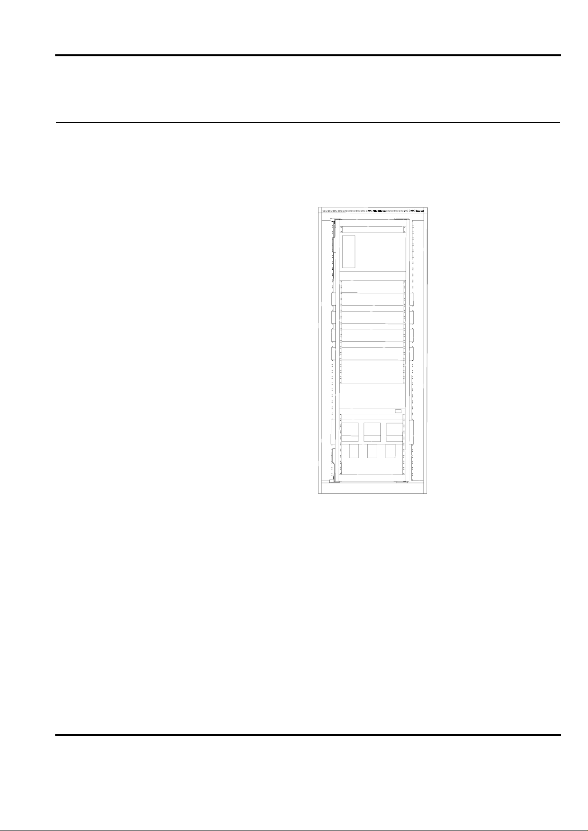
Figure 5-1. Typical Cabinet Configuration, Redundant Power Supply.......................... 5-1
Figure 5-2. Maximum cabinet configuratio n for Advan t Controller 410 with
S100 I/O assembled in RM500V1 cabinets.................................................. 5-2
Figure 5-3. Cabinet configuration for Advant Controller 410 assembled in RM500V2
cabinets......................................................................................................... 5-3
Figure 5-4. Compact version of Advant Controller 410 .................................................5-4
Figure 5-5. The size of the compact version of the Advant Controller 410.................... 5-5
Figure 6-1. The division of the I/O subrack.................................................................. 6-15
3BSE 015 966R201 Rev B v
Page 8

Advant Controller 410 Product Guide
Table of Contents
vi 3BSE 015 966R201 Rev B
Page 9

Advant Controller 410 Product Guide
Table of Contents
TABLES
Table 2-1. S800 I/O modules supported by Advant Controller 410..............................2-5
Table 2-2. Functions and configuration alternatives for Advant Controller 410......... 2-10
Table 3-1. PC elements in the basic program module QC01-BAS11............................ 3-2
Table 3-2. Functional units in the base program module QC01-BAS11....................... 3-3
Table 3-3. Additional PC elements in program module QC01-LIB11.......................... 3-4
Table 3-4. Additional PC elements in program module QC01-LIB12.......................... 3-5
Table 3-5. Functional units in the program module QC01-LIB12 ................................ 3-5
Table 4-1. Submodules.................................................................................................. 4-3
Table 4-2. System unit with single voltage regulator....................................................4-5
Table 4-3. System unit with redundant voltage regulator.............................................. 4-5
Table 4-4. Different power supply arrangements for Advant Controller 410 with
S100 I/O.....................................................................................................4-12
Table 5-1. RM500V1 configurations for Advant Controller 410 with S100 I/O .......... 5-3
Table 5-2. RM500V2 configurations for Advant Controller 410 with S100 I/O .......... 5-3
Table 6-1. The I/O limits of Advant Controller 410......................................................6-1
Table 6-2. The max. I/O configuration of Advant Controller 410.................................6-2
Table 6-3. The Width of the Connection Units.............................................................. 6-3
Table 6-4. The functional units limits of Advant Controller 410 ..................................6-4
Table 6-5. Number of buses/channels that can be connected to Advant Controller 4106-5
Table 6-6. Submodules that are possible to mount into the processor module.............. 6-6
Table 6-7. Relative time errors between events (DI signals).........................................6-8
Table 6-8. Data logging capabilities.............................................................................. 6-8
Table 6-9. Execution times............................................................................................ 6-9
Table 6-10. Examples of CPU load ............................................................................... 6-10
Table 6-11. The CPU load caused by data set communication......................................6-11
Table 6-12. T he CPU load caused by data set peripheral communication (cycle time of scan
task = 512 ms) .............................................................................................6-11
Table 6-13. Calculation of RAM Requirement.............................................................. 6-12
Table 6-14. Program module memory area on program card ........................................ 6-14
Table 6-15. The no. of slots in the I/O subrack ............................................................. 6-15
Table 6-16. RM500 cabinets dimensions....................................................................... 6-15
Table 6-17. RM500 cabinet protection classes..............................................................6-16
Table 6-18. Numbers of mounting bars in RM500V1 cabinets.....................................6-16
Table 6-19. Numbers of mounting bars in RM500V2 cabinet ......................................6-17
Table 8-1. General and Normative Requirements.........................................................8-3
Table 8-2. System Units................................................................................................. 8-3
Table 8-3. Processor Modules........................................................................................ 8-4
Table 8-4. AdvaControl Basic Functions and Incremental Licenses............................. 8-4
3BSE 015 966R201 Rev B vii
Page 10

Advant Controller 410 Product Guide
Table of Contents
Table 8-5. Optional Standard Program Modules ...........................................................8-4
Table 8-6. Optional Program Modules for Special Applications...................................8-5
Table 8-7. Telecontrol & SPA Bus.................................................................................8-5
Table 8-8. System Software Back-up Card....................................................................8-6
Table 8-9. Pr ogram Card Interface and back-up flash-PROMs.....................................8-6
Table 8-10. Free-programmable Module .........................................................................8-6
Table 8-11. MasterBus 300 and MasterBus 300E............................................................8-7
Table 8-12. G COM ..........................................................................................................8-7
Table 8-13. Advant Fieldbus 100 for coaxial cable ........................................................8-8
Table 8-14. Advant Fieldbus 100 for twisted pair cable.................................................8-8
Table 8-15. Modems for Advant Fieldbus 100................................................................8-8
Table 8-16. MasterFieldbus..............................................................................................8-9
Table 8-17. Details for MasterFieldbus............................................................................8-9
Table 8-18. Details for PROFIBUS-DP.........................................................................8-10
Table 8-19. Details for LON WORKS Network............................................................8-10
Table 8-20. Connection of MasterView 320, Printer and Excom..................................8-10
Table 8-21. Multi Vendor Interfaces ..............................................................................8-10
Table 8-22. Miscellaneous Communication Equipment................................................8-11
Table 8-23. P rinters........................................................................................................8-12
Table 8-24. Power Supply in RM500V1 Cabinet..........................................................8-13
Table 8-25. Power Supply in RM500V2 Cabinet..........................................................8-14
Table 8-26. Extra Power Supply for Field equipment ...................................................8-15
Table 8-27. Miscellaneous Power Supply Equipment................................................... 8-16
Table 8-28. Mains Supply Filter ....................................................................................8-16
Table 8-29. A nalog Input Sets for S100 I/O ..................................................................8-17
Table 8-30. Redundant Analog Input Sets for S100 I/O................................................8-18
Table 8-31. Analog Output Sets for S100 I/O................................................................8-18
Table 8-32. Analog Input/Output Sets for S100 I/O......................................................8-18
Table 8-33. Redundant Analog Input/Output Sets for S100 I/O....................................8-19
Table 8-34. Pulse Input and Positioning Sets for S100 I/O ...........................................8-19
Table 8-35. Digital Input Sets for S100 I/O...................................................................8-20
Table 8-36. Digital Output Sets for S100 I/O................................................................8-21
Table 8-37. Connection of Thyristor Converters...........................................................8-22
Table 8-38. S100 I/O boards for HART Protocol Interface...........................................8-22
Table 8-39. S100 I/O for Intrinsic Safety Isolator support (without connection units) .8-23
Table 8-40. Mounting Bars for Connection Units..........................................................8-25
Table 8-41. RM500V1 Cabi nets With=800 mm (3 1.5”), Depth=512 mm (20.2”).......8-26
Table 8-42. RM500V2 Cabinets
Table 8-43. RM500 Cabinet Accessories.......................................................................8-26
Width=700 mm (27.6”), Depth=637 mm (25.1”), Height=2225 mm (87.6”)8-26
viii 3BSE 015 966R201 Rev B
Page 11

Advant Controller 410 Product Guide
Table of Contents
Table 8-44. Documentation ........................................................................................... 8-27
Table 8-45. Software Utilities........................................................................................ 8-32
Table 8-46. System Unit ................................................................................................ 8-32
Table 8-47. Processor Modules......................................................................................8-32
Table 8-48. Software Licenses ....................................................................................... 8-33
Table 8-49. Optional Standard Program Modules.........................................................8-33
Table 8-50. Optional Program Modules for Special Application.................................. 8-33
Table 8-51. Telecontrol and SPA Bus............................................................................ 8-34
Table 8-52. System software Back-up Card ..................................................................8-34
Table 8-53. Program Card Interface and back-up flash-PROMs...................................8-35
Table 8-54. Free-programmable Module....................................................................... 8-35
Table 8-55. MasterBus 300 and MasterBus 300E.........................................................8-35
Table 8-56. GCOM ........................................................................................................ 8-36
Table 8-57. Advant Fieldbus 100 for coaxial cable....................................................... 8-36
Table 8-58. Advant Fieldbus 100 for twisted pair cable...............................................8-37
Table 8-59. Modems for Advant Fieldbus 100.............................................................. 8-37
Table 8-60. MasterFiel dbus ...........................................................................................8-38
T able 8-61. Details for PROFIBUS-DP.........................................................................8-38
T able 8-62. Details for LONWORKS Network .................................................... ...... ..8-38
Table 8-63. Connection of MasterView 320, Printer and Excom..................................8-38
Table 8-64. Multi Vendor Interfaces.............................................................................. 8-39
Table 8-65. Miscellaneous Communication Equipment................................................ 8-39
Table 8-66. Documentation on Compact version of Advant Controller 410.................8-41
Table 8-67. Software Utilities........................................................................................ 8-44
3BSE 015 966R201 Rev B ix
Page 12

Advant Controller 410 Product Guide
Table of Contents
x 3BSE 015 966R201 Rev B
Page 13
Chapter 1 Overview
Advant Controller 410 is a medium sized process controller for binary, regulatory and
supervisory control. Its wide-ranging process control and communication capabilities make it
the right choice for medium-sized, but functionally demanding applications in industrial
environments, either standing alone o r as an integrated par t of an Advant OC S system as well as
in any other distributed control system
Advant Controller 410 Product Guide
Section 1.1 Product Benefits
Figure 1-1. Advant Controller 410 with S100 I/O
1.1 Product Benefits
Advant Controller 410 is a full-function process controller in a minimal hardware configuration.
You will have the latest equipment concerning functionality, interoperability and performance.
You will be able to maximize your productivity and at the same time be prepared for easy
integration of tomorrow’s technology at a reasonable cost.
3BSE 015 966R201 Rev B 1-1
Page 14

Advant Controller 410 Product Guide
Chapter 1 Overview
1.2 Features
Advant Controller 410 covers a wide range of funct i ons such as:
• Logic and sequence control.
• Data and text handling.
• Arithmetic, reporting, positioning and regulatory control.
• Highly extended flexibility and scalability - hardware as well as software.
• Self-configuration capabilit ies which makes it possible to add units while the controller is
in full operation.
• Support of a wide range of central and distribu ted I/O modules for maximum configuration
possibilities, with a maximum I/O capacity of 4300 I/O points.
• Support of local and central HMI for manual control operations, event and alarm handling,
trend curve presentation etc.
• Interoperability concerning all commun ication levels from plant floor fieldbuses to highspeed plant network.
• Support of redundant Fieldbus Communication with Advant Fiel dbus 100.
• Support of Advant Fieldbus 100 with cable length up to 13300 meter (43300 feet).
1-2 3BSE 015 966R201 Rev B
Page 15

Chapter 2 Functional Description
2.1 General Controller Utilities
2.1.1 CPU
The processor module PM150V contains the total amount of RAM (Random Access Memory),
which is an 4 or 8 Mbyte dynamic RAM with error correction code. This memory holds the
system program which is in use as well as the controller system configuration and application
program, that is, all memory executed in run time. The processor module is built-up around
a microprocessor, Motorola 68020, running at 25 MHz.
The module front contains the following functions:
• Indicators and a character display for high level system diagnostics.
• The main operable equipment is a four-position rotary switch for start and working mode
selection and a restart push button.
Advant Controller 410 Product Guide
Section 2.1 General Controller Utilities
• The module front also includes a program card interface and four slots for submodules.
• You can connect a configuration and maintenance tool on the module front.
2.1.2 Memory and Backup
System Program Backup
The system program is backed up in flash PROM and loaded to the RAM in connection to
system start. Physically , the st andard system program is stored in one program card (PCMCIA).
Normally the program card should be in place during operation. Additional program cards are
located in program card interface MB510.
Application Program Backup
The controller system configuration and the application program is normally created in an offline or sometimes an on-line configuration session suppo rt ed b y an engineering station.
The work is basically backed up in the en gineerin g st ation e nviro nmen t (har d d isc, flexible disc
or likely ).
To restore a RAM which has been cleared by an accident or a fatal error some measures have
to be taken, automatically and manually. In addition to the automatic loading of the system
program, described above under the heading System Program Backup , somebody has
to manually load the application program backup (including the controller system config uration)
using an engineering station.
As an alternative the Advant Controller 410 can be equipped with an optional flash card
of similar type as the one used for the system pr ogram. The flash card is contained with a DUmp
of Application Programs (DUAP) preferably taken while the controller is in the operation mode.
3BSE 015 966R201 Rev B 2-1
Page 16

Advant Controller 410 Prod uct Guid e
Chapter 2 Functional Description
At need, the controller system configuration and the application program is likewise
automatically loaded from its flash card into the controller RAM. No manual intervention is
needed to get into operation after the interruption.
Flash cards are available in different memory-sizes (2, 4 or 10 Mbytes). Select a type that take
the actual application program.
The system program backup and the application pr ogram b ackup can not be mixed in one si ngle
program card.
Memory Backup Power Supply
The RAM is secured against loss of power for a minimum of four hours by a backup power
supply and battery. This is important for the configured application program, which is basically
not otherwise backed up.
If a longer backup time is desirable, you can use an application program backup (see heading
above).
2.1.3 System Clock, External Clock Synchronization
The processor module PM150V is provided with a calendar clock which is backed up by
the same battery used for memory backup. You can set the date and time from the programming
unit or from a local operator station, for example, MasterView 320. A slow, smaller adjustment
in the interval ±100 s can also be perfor med with the programming unit.
With Advant Controller 410 connected to MasterNet, as a part in a distributed control system,
the synchronization occurs automatically with other stations via a network with an accuracy
better than 3 ms.
2.1.4 Configuration
2.1.5 Execution
If extreme synchronization accuracy is required between controllers (in the order of 2 ms) and
synchronization to an external clock, an external minute pulse signal can be connected to all
systems concerned.
The supervision module SB171 has a special input for external synchronization of
the calendar clock.
You configure the system in accordance with the hardware and software selected, for example,
the number of I/O boards, communication lines, functional units and PC programs.
This is performed using commands from a configuration tool su ch as Advant Station 140 (with
AMPL Control Configuration 1.7 or later product versio ns ) and results in the internal
organization and activation of the data base and program areas.
The execution units in a PC program are normally given cycle times of 10 ms - 2 s (5 ms - 32 s
after reconfiguration). The internal program system (operating system and PC interpreter)
organizes the execution of the units with the periodicity selected, simultaneously performing
other tasks such as communication with a MasterView 320 and programming units.
Ordinarily, you can select the same cycle times for reading in values from digital and analog
boards.
2-2 3BSE 015 966R201 Rev B
Page 17

2.1.6 Start-up
2.2 Process Control
Advant Controller 410 Product Guide
Section 2.1.6 Start-up
The CPU front panel has a rotary switch to select start and working mode. The normal position
of the switch is 1 (AUTO). This means an automatic start when voltage is switched on or when
voltage is recovered after a power failure. At an interruption of voltage, the system stores all
the information necessary for restarting. Whether the system is to continue operations from its
status at the interruption of the voltage or if it is to be reset to zero before restart is selected with
parameters.
The different ways to start are CLEAR, STOP, AUTO or OFF LINE. The way to start is selected
on the basis of the duration of the voltage failure.
You can connect a control module which is activated when the voltage returns and which
executes one cycle to each start alternative. All start modules must belong to the same
PC program. You can define how the process is to start with these control modules.
Alarm can also be blocked at initialization of the I/O boards.
Process control applications are programmed in the ABB Master Programming Language
(AMPL). AMPL is a function-block language with graphic representation.
The building blocks are called PC elements. There is a wide range of PC elements, from simple
AND blocks to complete PID regulators.
Besides the functional PC elements, AMPL also contains several structural elements for
dividing a PC program into suitable modules which can be managed and executed individually.
The controller can be programmed fully on-line, that is, with the program running and
controlling the process.
PC Elements
The range of ready-to-use PC elements is wide and powerful. It contains, for example,
elements for:
• Logic and Time Delays
• Sequence Control
• Data and Text Handling
• Calendar Time Functions
• Arithmetic
• Feedback Control
• Pulse counting and Frequency Measurement
• Positioning
• Reports
• Communication via Fieldbuses
The PC elements are listed under the program modules in Chapter 3, Software Components.
3BSE 015 966R201 Rev B 2-3
Page 18

Advant Controller 410 Prod uct Guid e
Chapter 2 Functional Description
User Defined PC Elements
Another way to implement your frequently used control solution and ensure a fully integrated
engineering environment is to make use of the optional program module User Defined
PC Elements.
A user defined PC element appears in every sense as a standard PC element. Actually
the control solution of a user defined PC element is defined by other PC elements.
By designing your application with user defined PC elements you gain:
• Significant reductio n in tr anslation time.
• Memory saving with reuse.
• Similar documentation in Function Chart Builder and On-line Builder.
• User defined PC element hierarchy.
• Reduc ed man-hours in commissioning and mai ntenance.
Functional Units
A functional unit is a package of different functions, such as PC elements, DB elements, display
elements, dialogs and event and alarm handling. Functional units extend the power of AMPL
and supplement the PC element library for more complex control functions.
Since the functional units are ready-to-use, it simplifies documentation and implementation of
functions with both control function and associated operator’s action via display screen and
keyboard. The operator interface is always co nsistent to impr ove the operator’s interaction with
the process. Application include regulators, sequence control and motor/valve controls.
PC elements and functional units can be used freely together.
The functional units are listed under the program modules in Chapter 3, Software Components
2-4 3BSE 015 966R201 Rev B
Page 19

2.3 I/O System Support
S100 I/O System
S100 I/O boards (up to 15 boards) are located in the same subrack as the CPU. For further
information about S100 I/O, please refer to the Product Guide for S100 I/O.
S800 I/O System
The distributed S800 I/O modules communicate with the Advant Controller 410 over the
Advant Fieldbus 100, via the CI522A interface module. The fieldbus communication between
the controller and the modulebus in the S800 I/O station can be doubled (redundancy).
The range of supported S800 I/O modules is shown in Table 2-1.
Module type Type designation
Advant Controller 410 Product Guide
Section 2.3 I/O System Support
Table 2-1. S800 I/O modules supported by Advant Controller 410
FCI CI810xx, CI820, CI830
AI AI801, AI810, AI820, AI830, AI835, AI890, AI895
AO AO801, AO810, AO820, AO890, AO895
DI DI801, DI810, DI811, DI814, DI820, DI821, DI830, DI831, DI885,
DI890
DO DO801, DO810, DO814, DO815, DO820, DO821, DO890
DP DP820
For further information about S800 I/O please refer to the Product Guide for S800 I/O.
2.4 Time Tagging of Events and Alarms
The time tagging of digital input signals can be done in the system software of the controller or
on certain digital input (DI) boards belonging to S100 I/O. Time tagging on a DI board results in
a high time accuracy. Signals created in AMPL can also be time tagged but with an accuracy
corresponding to the PC program cycle time.
2.5 Pulse Counting and Positioning
Pulse Counting
Different S100 I/O and S800 I/O boards are used for pulse counting. Low pulse frequencies
(lower than 40Hz) are counted without PC element support.
For higher frequencies (up to 2.5 MHz), PC elements are connected to the boards.
3BSE 015 966R201 Rev B 2-5
Page 20
Advant Controller 410 Prod uct Guid e
Chapter 2 Functional Description
Positioning
Positioning and length measurement uses a set of PC elements connected to the board
DSDP 140A. Fast positioning creates substantial load in the controller CPU. Normally,
max. 10 positioning axes per Advant Controller 410, can be used.
2.6 Switchgear Integration
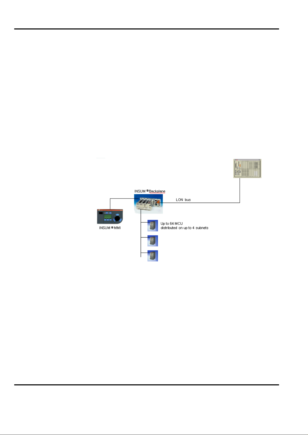
Connection to the INSUM Motor Control Unit (MCU) is done via the LONWORKS Network.
ONWORKS channel (on CI572 Communication Module) can connect one INSUM Motor
Each L
Controll er, includi ng u p to 64 MCU’s. A series of PC element is used for sending/receiving data
to/from the MCU’s.
To minimize engineering efforts, a predefined type circuit is offered.
For configuration of the L
ONWORKS Network the configuration tool LNT505 is required in
addition to the ordinary Advant Control Configuration tool. See Advant Engineering Products,
Product Guide for further information.
Advant Controller 410
with CI57x LON interface
Figure 2-1. AC 400 Ser ies co nfiguration with INSUM Motor Controller
2.7 Drives Integration
Connection to ACS 600, DCS 600 and DCS 5008 drive systems, is done via Advant Fieldbus
100. Each fieldbus node connects up to 24 drives via a S800 I/O Fieldbus Communication
Interface (FCI). A series of PC elements is used for sending/receiving data to/from the drives.
In order to minimize engineering efforts, a predefined type circuit is offered.
2-6 3BSE 015 966R201 Rev B
Page 21

AF 100
Section 2.8 Variable Speed Drive Control
Adva nt C o ntroller 40 0 Se ries
I/O I/O
S8 0 0 I/ O
Advant Controller 410 Product Guide
AdvaCom man d
O p t ic a l M od u le B u s
2.8 Variable Speed Drive Control
Converters for both d.c. and a.c. motor drives can be connected to Advant Controller 410 via
Advant Fieldbus 100 or MasterFieldbus. For TYRAK, which has a built in modem for
the MasterFieldbus, the following limitations apply:
• The max. no. of convertors connected to the same LDB is 9.
• The max. no. of convertors connected to one Advant Controller 410 is 64.
2.9 Communication
Detailed information about the various networks and busses that can be integrated in Advant
Controller 410 is given in Product Guide for Advant OCS with Master Software, Overview.
Below is a list of communication functions in Advant Controller 410.
Control Network
• MasterBus 300
Communication is done with Data Sets
• MasterBus 300E
Communication is done with Data Sets
Figure 2-2.
$&6HULHVFRQILJXUDWLRQZLWKGULYH
Fieldbus Communication
• Advant Fieldbus 100
Communication is done with Data Set Peripherals or with PC elements
• PROFIBUS-DP
Communication is done with PC elements
• RCOM/RCOM+
Communication is done with MVI Sets
• Master Fieldbus
Communication is done with PC elements
• L
ONWORKS Network Interface
Communication is done with PC elements
3BSE 015 966R201 Rev B 2-7
Page 22

Advant Controller 410 Prod uct Guid e
Chapter 2 Functional Description
External Communication
• EXCOM
Communication is done with Data Sets
• MultiVendor Interface (MVI)
Communication is done with MVI Sets
The following protocols are supported:
– MODBUS (via CI532V02 and database element MS)
– MODBUS (via CI534V02 and database element MVB)
– Siemens 3964(R) (via CI532V03 and database element MS)
– Allen-B radley DF1 (via CI534V04 and database element MVB)
– Free-programmable protocol (via CI535 and database element MS)
– Free-programmable protocol (via CI538 and database element MVB)
• GCOM
Communication is done with Data Sets
• HART data routing
HART data can be routed between S800 I/O modules supporting HART and a
configuration tool supported by the AMPL Control Configuration.
Telecontrol & SPA Bus
• RCS protocol RP570/RP571 Master
• RTU protocol RP570 Slave
• RTU protocol IEC870-5-101 unbalanced Secondary Station
• SPA Server protocol SPA Bus
Communication is done with PC elements. For further information s ee res pective
Product Guide.
2.10 AdvaCommand Support
Advant Controller 410 supports several functions in an Advant Operator Workplace:
• Subscription
• Order and presentation
• System Status Displays
• Status List
• Trend displays
• Event List
2-8 3BSE 015 966R201 Rev B
Page 23
Section 2.11 Local Operator Station MasterView 320
For further information, please see the Product Guide for Advant Operator Workplace with
AdvaCommand.
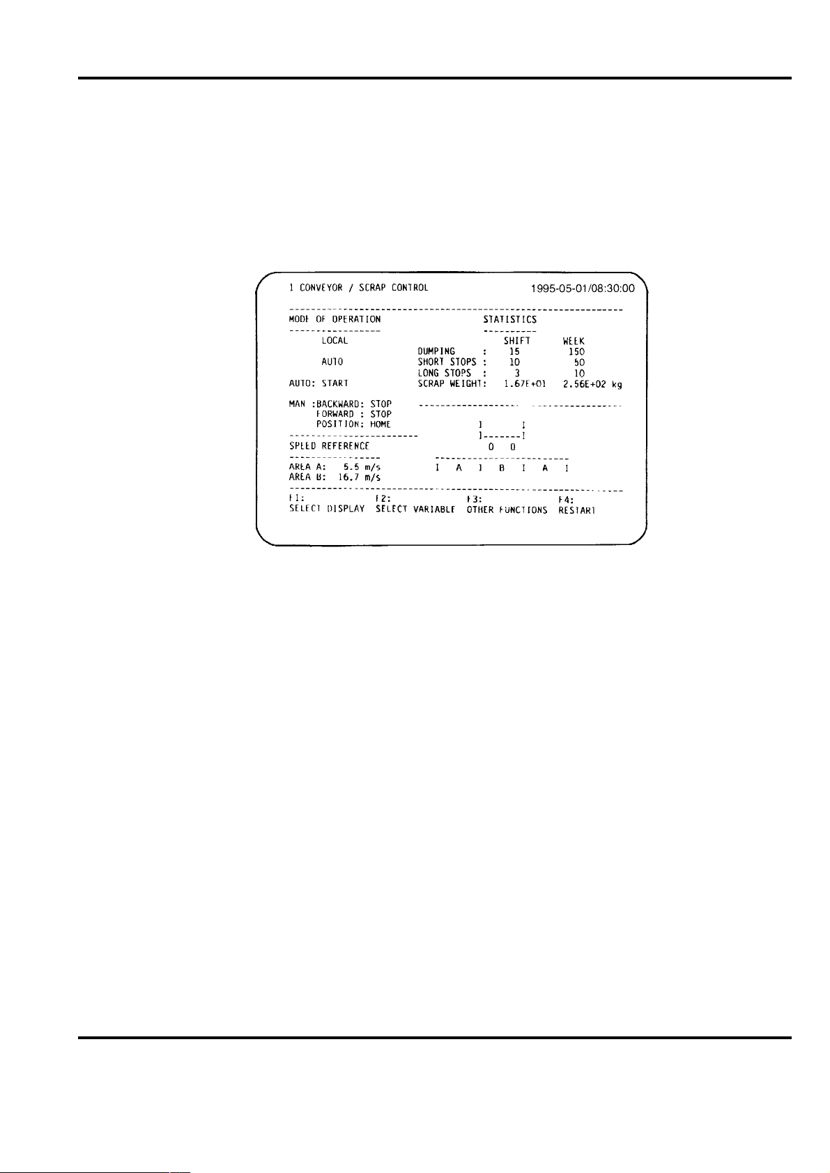
2.11 Local Operator Station MasterView 320
MasterView 320 provides functions for presentation of process information on user defined
displays, for manual data entry via a keyboard, and for presentation of an event list with events
generated by application programs in Advant Controller 410.
Advant Controller 410 Product Guide
Figure 2-3. Example of display from MasterView 320
Hard-copy printout of displays and event list is possible.
Display Presentation and Operator Dialog
MasterView 320 is a VT100 or VT100 compatible terminal, 24 lines with 80 characters per line.
16 of the lines are available for user defined displays. The remaining eight lines are used by
the system for display identity and description presentation, time and date, dynamic function
key menu and a command entry line. Displays are generated and modified directly on the
screen. Standard VT 100 attributes, such as reverse video, flashing, underscore and reduced
intensity are supported. The static part of a display is built using text strings.
Depending on terminal, simple character oriented graphics are supported. Dynamic fields are
defined for the presentation of information from variables in the data base. Integer and real
values are presented in numerical form. Time is presented in the form HH:MM:SS. Boolean
values can be presented with user defined text strings; ON/OFF, UP/DOWN and AUTO/
MANUAL. Each display is given an identity and a description; presented on the display’s first
line. You can protect displays from unauthorized modification by a parameter in the database.
A simple operator dialog is engaged into through the function keys on the keyboard. By setting
a parameter value, you select one of the following languages: Danish, Dutch, English, Finnish,
French, German, Italian, Norwegian, Portuguese, Spanish, and Swedish.
3BSE 015 966R201 Rev B 2-9
Page 24

Advant Controller 410 Prod uct Guid e
Chapter 2 Functional Description
Event List
Event list is available via MasterView 320. It can be presented on the terminal screen and
printed on a printer connected to the controller. A separate list is associated with each screen.
The event generation is configured with PC programs, using PC element EVENT. Event texts
are user defined. The time of each event is automatically incorporated, with a resolution
determined by the scanning cycle of the PC program where the event is generated.
Hard Copy
A printer, connected to the same Advant Controller 410, can be used for hard-copy printouts
from MasterView 320. The printout can be activated from the keyboard, or automatically from
an PC program in the controller. The hard-copy function of MasterView 320 can be used for
efficient report generation with the controller. All necessary calculations of report data is done
with PC programs. The report is built with the normal display generatio n functio ns of
MasterView 320. Once the report is defined, the video terminal is not required any more, only
the hard-copy printer. Printout is then activated from PC programs. Thus reports can be
generated at regular points in time or on special events.
2.12 Local Printer
With a printer, directly connected to the Advant Controller 410 via conn ector on the C PU fron t,
reports (generated in AMPL report function) or report/event lists from MasterView 320 can be
printed.
2.13 Scope of Controller Functions
A large variety of configuration alternatives is possible with Advant Controller 410 and its I/O,
both software and hardware. Software options are available as one or several program modules.
Optional hardware units are I/O boards, communication units etc. Table 2-2 summarizes the
various options and configuration alternatives applying to Advant Controller 410.
Table 2-2. Functions and configuration alternatives for Advant Controller 410
Function Program module Hardware Peripherals
S100 I/O boards with Board Oriented Connection Units
Redundant S100 I/O boards with Board
Oriented Connection Units
S400 I/O units QC01-BAS11
QC01-BAS11 See Refer-
QC01-BAS11 DSAX 110
ence Guide
DSAX 110A
DSAI 133
DSAI 133A
DSTA 001
DSTA 001B
DSTA 002
DSTA 002B
(1)
MasterFieldbus
2-10 3BSE 015 966R201 Rev B
Page 25

Advant Controller 410 Product Guide
Section 2.13 Scope of Controller Functions
Table 2-2. Functions and configuration alternatives for Advant Controller 410 (Continued)
Function Program module Hardware Peripherals
S800 I/O modules QC01-BAS11 See S800 I/O
Product Guide
Local time-tagging on DI-board with down
to 1 ms resolution
QC01-BAS11 DI885, DI830,
DI831
DSDI 1 10A
DSDI 1 10AV1
DSDI 120A
DSDI 120AV1
PC elements for logic, arithmetic & data
QC01-BAS11
handling
PC elements for logic, arithmetic, data
handling and process control
PC elements for logic, arithmetic, data
handling and advanced process control
QC01-BAS11+
QC01-LIB11
QC01-BAS11+
QC01-LIB11+
QC01-LIB12
Functional units QC01-BAS11+
(QC01-LIB12)+
QC01-OPF11
Positioning QC01-BAS11 DSDP 140A
DSTD 150A or
DSDP 140A
DSTD 190
Advant Fieldbus 100
AdvaCommand
Pulse transmitter
Fast pulse counting and frequency measurement
QC01-BAS11 DSDP 150
DSTD 150A or
DSDP 150
DSTD 190 or
DSDP 170
DSTX 170
Local operator station
MasterView 320
Local printer
(2)
(2)
QC01-BAS11+
QC01-LOS11
QC01-BAS11 CI531
CI531
Modem
Modem
External computer communication using
EXCOM
QC01-BAS11 CI531
Modem
MasterBus 300 QC01-BAS11 CS513/CI547
Transceiver
MasterBus 300E QC01-BAS11 CS513/CI547
Transceiver
Pulse transmitter
VT 100-compatible terminal
Printer
External computer with EXCOM.
MasterNet
MasterNet
3BSE 015 966R201 Rev B 2-11
Page 26

Advant Controller 410 Prod uct Guid e
Chapter 2 Functional Description
Table 2-2. Functions and configuration alternatives for Ad vant Controller 410 (Continued)
Function Program module Hardware Peripherals
GCOM QC01-BAS11 CI543
Communication using RCOM/RCOM+ QC01-BAS11 CI532V01
MultiVendor Interface QC01-BAS11 CI532Vxx
CI534Vxx
Free-programmable
MultiVendor Interface
Telecontrol & SPA Bus QC01-BAS11+
QC01-BAS11 CI535 or
CI538
CI535V24
YC571
CI535V29
CI535V23
CI535V26
CI535V30
Telecontrol & SPA Bus QC01-BAS11+
YC565
MasterFieldbus QC01-BAS11 CI570,
TC570
Advant Fieldbus 100 QC01-BAS11 CI522A
TC512V1
TC513xx
TC514xx
TC515xx
TC516
TC625
TC630
PROFIBUS-DP QC01-BAS11 CI541V1
Software development environment required
S400 I/O units, TYRAK, SAMI
Advant Controller 70/110,
S800 I/O, DCS 500B, DCS 600,
ACS 600
ONWORKS Network Interface QC01-BAS11 CI572 INSUM2
L
Support for AdvaCommand, AdvaSoft
for Windows, AdvaInform and MV 800/1
QC01-BAS11+
QC01-OPF11
CS513/CI547
Transceiver
MasterNet
(Subscription, Order/Presentation, System
Status, Status List, Trend, Event List)
Table handling QC01-BAS11
On-line PC program editing QC01-BAS11 On-line Builder (AdvaBuild, AMPL
Control Configuration, AdvaCommand)
Connection to analog thyristor converters,
variable speed control
QC01-BAS11+
QC01-LIB11
DSDC 111
DSTX 110
Thyristor converter
2-12 3BSE 015 966R201 Rev B
Page 27

Advant Controller 410 Product Guide
Section 2.13 Scope of Controller Functions
Table 2-2. Functions and configuration alternatives for Advant Controller 410 (Continued)
Function Program module Hardware Peripherals
MasterBatch 200/1 support QC01-BAS11+
QC01-BAT11
CS513/CI547
Transceiver
Intrinsic Safety support QC01-BAS11 DSAI 130
DSAI 130A
DSAI 133
DSAI 133A
DSAO 120
DSAX 110
DSAX 110A
DSDI 1 10A
DSDI 1 10AV1
DSDO 115A
DSDP 150
HART Protocol support QC01-BAS11 DSAI 133
DSAI 133A
DSAX 110
DSAX 110A
DSAO 120
DSAO 130
DSAO 130A
Support for ACS 600, DCS 600 and DCS
500B motor drives
QC01-BAS11 See Advant
Fieldbus 100
MasterNet
Intrinsic Safety Isolator
modules.
See S100 I/O Product Guide for
more information.
HART multiplexer
See S100 I/O Product Guide for
more information.
Motor Drives ACS 600, DCS 600
and DCS 500B Advant Fieldbus
100
User Defined PC elements QC01-BAS11+
QC01-UDP11+
(QC01-LIB11)+
(QC01-LIB12)
PROM back-up of application program
QC01-BAS11 MB510
(PC programs and data base)
(1) A classic product and no longer includ ed i n sta nda rd offeri ng
(2)Modem TC562 is required for distances longer than 15 m (49 ft.)
Flash-PROM
card
Engineering station
Engineering station with PCMCIA
card support
3BSE 015 966R201 Rev B 2-13
Page 28

Advant Controller 410 Prod uct Guid e
Chapter 2 Functional Description
2-14 3BSE 015 966R201 Rev B
Page 29

Chapter 3 Software Components
3.1 Overview
Advant Controller 410 system software comprises a real-time operating system and an AMPL
execution machine.
The functional extent of Advant Controller 410 is determined by adding optional software and
hardware units to the basic unit. The software options are delivered as program modules which
may be selected to create the desired functional configuration. Optional hardware units are
I/O and communication modules etc.
The software system for Advant Controller 410 is built around one Basic program module to
which Optional alternative program modules can be added. The Optional program modules can
be combined in a number of combinations needed to solve the application tas k. A descriptio n of
the program modules and a specification of their contents is given below. The Basic program
module, QC01-BAS11, together with the optional software below are stored in one program
card, placed on the CPU PM150V.
Advant Controller 410 Product Guide
Section 3.1 Overview
3.2 Basic Program Module, QC01-BAS11
The Basic program module has the following functional contents:
• Logic control and time delays
• Arithmetic
• Data and text handling
• Sequence control
• Calendar time functions
• Table handling
• Fast pulse counting and frequency measurement
• Positioning
• Reports
• Functional units, binary
• Functional units, analog
• Functional units, motor and valve control, group start
• Support for MasterBus 300/300E
• Support for GCOM
• Support for RCOM/RCOM+
1. The PC elements and database parts of the functional units are included in the Basic program modul e .
The presentation and di alog support require the opti onal Program Module QC01-OPF11. Special dedicated
interface boards are not included in the system unit.
1
1
1
3BSE 015 966R201 Rev B 3-1
Page 30

Advant Controller 410 Prod uct Guid e
Chapter 3 Software Components
• Support for MultiVendor Interface
• Support for fieldbus communica t ion (Advant Fie l dbus 100, PRO F IBUS-DP, L
ONWORKS
Network, MasterFieldbus).
• Strain-gauge weighing support
• Support for motor drives
• Data Set/DAT communication
• Back-up of application program in flash-PROM card
Most of the above mentioned functions are realized with one or several PC elements.
The contents of the PC element library in the basic program module is shown in Table 3-1.
Table 3-1. PC elements in the basic program module QC01-BAS11
T ype PC element
Structure elements PCPGM, CONTRM, FUNCM, MASTER, SLAVEM,
BLOCK, SEQ, STEP
Logic elements AND, OR, AND-O, OR-A, XOR, INV, SR, SR-D, SR-AA,
SR-AO, SR-OO, SR-OA
Arithmetic elements ADD, SUB, MUL, DIV, ADD-MR1, ADD-MR,
DIV-MR, SQRT, ABS, LIM-N
Time delays TON, TOFF, MONO, TON-RET, TRIGG, OSC-B
Calendar time elements TIME, DATE, TIMER
Registers SHIFT, SHIFT-L, FIFO, REG-RET, EXPAND, EXPAND-
A, FIFO-RW, REG, REG-G
Multiplexers MUX-I, MUX-N, MUXA-I, MUX-MI, MUX-MN,
DEMUXA-M, DEMUX-MI
Code converters CONV-BI, CONV-IB, CONV-AI, CONV-IA,
CONV-SA, CONV
Counters COUNT, COUNT-L
Comparators COMP-I, COMP-R, COMP, MAX, MIN
Fault elements F AUL T
Printing and text generation
TEXT, PRINT
elements
Elements for functional
units
GENBIN-I, GENBIN-O, GENUSD-I, GENUSD-O, GEN-
CON-I, GENCON-O, MOTCON,
VALVECON, MMC-IND, MMC-ORD
Switches SW, SW-C
Positioning elements POS-A, POS-O, POS-L
3-2 3BSE 015 966R201 Rev B
Page 31

Advant Controller 410 Product Guide
Section 3.2 Basic Program Module, QC01-BAS11
Table 3-1. PC elements in the basic program module QC01-BAS11 (Continued)
Type PC element
Pulse counting and frequency measurement
PULSE-S, COUNT-DP, FREQ-SP, FREQ-MP, PCU-I,
PCU-O, PCU-COM, PCU-SS
elements
Data handling elements MOVE, MOVE-A
Event handling element EVENT
Report element REPORT
Elements for programma-
FPM-COM, FPM-I, FPM-IA, FPM-O, FPM-OA
ble module
Weighing elements SCALE, SCALEDOS
Table handling elements TBL-R, TBL-RG, TBL-W, TBL-WG
Ramp generators RAMP-S1
Supervision elemen ts ANALYSE, COM-STAT
MasterFieldbus
communication elements
Advant Fieldbus 100
COM-MP51, MFB-OUT, MFB-IN, COM-CVI1, COMCVO1
DSP-R, DSP-S, DRI-CNV, DRI-R, DRI-S
communication elements
PROFIBUS-DP
PB-DIAG, PB-R, PB-S
communication elements
ONWORKS Network
L
LON-R, LON-S
Interface
communication elements
Data Set elements SENDREQ
Besides the PC element library , the b asic program modu le also includes a functional u nit library.
The functional units supplement the PC elements and they are primarily intended for realizing
instrumentation functions. The contents of the functional unit library is shown in Table 3-2.
Table 3-2. Functional units in the base program module QC01-BAS11
Functional unit Description
AI Analog input signal, including AI, Temp. (Pt100), TC
(thermocouple), AIC (cal cu la ted AI)
AO Analog output signal, including AO and AOC (calculated
AO)
DI Digital input signal, including DI and DIC (calculated DI)
DO Digital output signal, including DO and DOC (calculated
DO)
3BSE 015 966R201 Rev B 3-3
Page 32

Advant Controller 410 Prod uct Guid e
Chapter 3 Software Components
Table 3-2. Functional units in the base program module QC01-BAS11 (Continued)
DAT General data base value
TEXT Text in data base
GENUSD General user-defined device controller
GENBIN User-defined on/off controller
GENCON User-defined regulatory controller
SEQ Sequence controller
GROUP Device group controller
MOTCON Motor controller
VALVECON Valve controller
DRICONE Engineered Drives Controller
DRICONS Standard Drives Controller
Functional unit Description
MOTCONI INSUM Motor Controller
3.3 Optional Program Module, QC01-LIB11
The Optional program module QC01-LIB11 extends the PC element library that is included in
the Basic program module with PC element for supporting the function:
• Feedback control
• Connection to analog thyristor conv e rters .
Feedback control is realized with PC elements. The contents of PC elements in QC01-LIB11 is
shown in Table 3-3.
Table 3-3. Additional PC elements in program module QC01-LIB11
T y pe PC element
Logic elements THRESH-L
Arithmetic elements MED-R, MAJ-R, LN, EXP
Multiplexers MUXGR-MI, MUXGE-MI
Time controlled elements OSC-SQW, OSC-SIN
Function generators FUNG-1V, FUNG-2V, FUNG-T
Filter elements FIL T-1P, FILT-2P
3-4 3BSE 015 966R201 Rev B
Page 33

Advant Controller 410 Product Guide
Section 3.4 Optional Program Module, QC01-LIB12
Table 3-3. Additional PC elements in program module QC01-LIB11 (Continued)
Type PC element
Feedback control elements P-DEADB, P-1, INT, DER, PI, PIP, PDP, CON-PU1,
RAMP
Analog thyristor converter
CVB-I, CVB-O
elements
3.4 Optional Program Module, QC01-LIB12
The Optional program module QC01-LIB12 extends the PC element and functional units
libraries that are included in the Basic program module with PC element for supporting
the functions below:
• Regulatory control
• Functional units, PID loop control, PIDCON
• Self-tuning adaptive control, Novatune.
The functions are realized with the PC elements in Table 3-4.
Table 3-4. Additional PC elements in program module QC01-LIB12
Type PC element
Elements for functional
units
Self-tuning controller NOVATUNE
PIDCON, RATIOSTN, MANSTN
1
The PC elements PIDCON, RA TI OSTN and MANSTN are also part of the following functional
units, which is shown in Table 3-5.
Table 3-5. Functional units in the program module QC01-LIB12
Functional unit Description
PIDCON Regulatory controller
RA TIOSTN Ratio station
MANSTN Manual statio n
1. The PC el em e n t s and database parts of the functional units are included in QC01-BAS11 and QC01-LIB12. The
presentation and dialog support require QC01-OPF11.
3BSE 015 966R201 Rev B 3-5
Page 34

Advant Controller 410 Prod uct Guid e
Chapter 3 Software Components
3.5 Optional Program Module, QC01-OPF11
The Optional program module QC01-OPF11 extends the functionality of the controller with
support for operator station functions in for example Advant Operator Wo rkplace or
MasterView 800/1.
The Optional program module QC01-OPF11 extends the functionality given by the Basic
program module with the following functions:
• Functional units, binary
• Functional units, analog 1
• Functional units, PID lo op control, PIDCON
• Functional units, motor and v alve control, group start
• Support for AdvaCommand Functions
(Subscription, Order/Presentation, System Status, Status List, Trend, Event/Alarm)
• Log data storage
• Group alarm, a function in AdvaCommand Event and Alarm
1
1
1
3.6 Optional Program Module, QC01-LOS11
Optional program module QC01-LOS11 extends the functionality of the controller with
MasterView 320. A VT100 terminal (or compatible) is used as operator interface.
Three such terminals can be connected to an Advant Controller 410, thus providing three local
operator workplaces. Optional program module QC01-LOS11 extends the functionality given
by the Basic program module with the following functions:
• MasterView 320
• Reports for MasterView 320.
3.7 Optional Program Module, QC01-BAT11
The Optional program module QC01-BAT11 extends the functionality of the controller with
support for connecting it to the batch station MasterBatch 200/1.
MasterBatch 200/1 is connected to Advant Controller 410 through MasterNet.
3.8 Optional Program Module, QC01-UDP11
The Optional program module QC01-UDP11 makes it possible to execute user defined PC
elements in the Advant Controller 410. The user defined PC element is created in AMPL
Control Configuration (1.7 or a later product version) and built-up of a combination of normal
PC elements from the standard PC element libraries of the Advant Controller 4 10. After the user
defined PC element is installed in the Advant Controller 410 it can be us ed freely in all
PC programs as a normal PC element.
3-6 3BSE 015 966R201 Rev B
Page 35

Chapter 4 Hardware Components
4.1 Pro cessor Module
PM150V is a processor module for Advant Controller 410. It is designed to fit into
DSRF 198/199 S100 I/O subracks.
The processor module, PM150V (Figure 4-1 refers), has the following characteristics:
• 25 MHz 68020 Proces sor
• 4 or 8 Mbyte Dynamic RAM with ECC
• The RAM houses the system software as well as the user built application
• Interface to up to four submodules on module front (see Figure 4-1 slot #1-4)
• Two RS-232-C interfaces
– one for MasterView 320 (connector X17)
Advant Controller 410 Product Guide
Section 4.1 Processor Module
– one for printer connection (connector X6)
• One slot for PCMCIA program card on front (see Figure 4-1 slot #5)
• Service tool, Advant Station 100 Series, interface on front (see Figure 4-1 connector X27)
The processor module exists in two versions which have the same type designation on the front,
PM150V, and can be separated by the label on the component side of the module.
• PM150V04 with 4 Mbyte read/write memory (RAM)
• PM150V08 with 8 Mbyte read/write memory (RAM).
PM150V04 is upgradable to PM150V08 with a special kit containing 8 Mbyte RAM.
3BSE 015 966R201 Rev B 4-1
Page 36

Advant Controller 410 Product Guide
Chapter 4 Hardware Components
RUN
HLT
MIB
X17
COM1
F
2
1
3
ENTER
TO
1=AUTO
2=STOP
3=CLEAR
4=OFFLINE
4
PM
150V
X6
COM2
DCOK
INHIB
BC
SERVICE
5
X27
4
1
2
3
Figure 4-1. Front View of the PM150V Processor Module
Indicator LEDs on module front are:
Name LED Color Description
F red Module Error
RUN green Module running normally
HLT red CPU h alted
TO yellow Bus Time-out
MIB yellow MP150 is current bus master on MIB
DCOK green 24 V d.c. supply is within range
INHIB yello w INHIB is active
BC green Backup voltage for RAM connected
4-2 3BSE 015 966R201 Rev B
Page 37

4.2 Program Card
The controller system software is stored on a flash memory card of type PCMCIA.
This card is located in a slot (see Figure 4-1 slot #5) on the CPU PM150V. It is accessed during
start-up of the controller and supervised in run-time.
4.3 Submodule Carriers
The purpose of the submodule carrier is to carry communication interfaces and other
submodules. The CPU, PM150V, is the submodule carrier containing four slots.
4.4 Submodules
Communication interfaces and a few other functions are realized as submodules which fits into
a slot on the CPU. Modules can be exchanged while the system is running. New modules can
also be inserted live. Every unit has a red LED to indicate fault, see Table 4-1.
Submodule Description
Advant Controller 410 Product Guide
Section 4.2 Program Card
Table 4-1. Submodules
CI531 RS-232-C communication interface for printer, EXCOM or
MasterView 320. Each interface holds two RS-232-C lines.
CS513 or CI547 MasterBus 300, MasterBus 300E communication. Each interface
holds one line. CI547 includes a slave CPU and will thereby
reduce load from the main CPU module (PM150)
CI532V01 RCOM/RCOM+ communication. Each interface holds two lines.
CI532V02 MODBUS communication with DB element MS. Each interface
holds two lines.
CI532V03 Siemens 3964(R) communication. Each interface holds two lines.
CI534V02 MODBUS communication with DB element MVB. Each interface
holds two lines.
CI534V04 Allen-Bradley DF1 communication with DB element MVB. Each
interface holds two lines.
CI535V24 RCS protocol RP570 Master
CI535V29 RCS protocol RP571 Master
CI535V23 RTU protocol RP570 Slave
CI535V26 RTU protocol IEC870-5-101 Unbalanced
CI535V30 SPA Server protocol SPA Bus
CI535 Free-programmable MVI communication with DB element MS.
Each interface holds two lines.
CI538 Free-programmable MVI communication with DB element MVB.
Each interface holds two lines.
3BSE 015 966R201 Rev B 4-3
Page 38

Advant Controller 410 Product Guide
Chapter 4 Hardware Components
Submodule Description
CI541V1 PROFIBUS-DP communication. Each interface holds one line.
Table 4-1. Submodules (Continued)
4.5 Subrack
CI572 L
CI543 GCOM communication. Each interface holds one line.
CI570 MasterFieldbus communication. Each interface holds one line
CI522A Advant Fieldbus 100 communication. Each interface holds one
MB510 Program card interface for extra system software or application
PU535 Free-programmable module
The processor module (PM150V) for Advant Controller 410 is a unit which fits into a special
version of the S100 I/O subr ack.
ONWORKS Network communication, 1250 kbit/s. Each interface
holds two lines.
with cable redundancy capabilities.
line with cable redundancy capabilities.
backup
PM150V
Figure 4-2. The processor module, PM150V, within the S100 I/O subr ack
The subrack can contain PM150V and up to 15 S100 I/O boards. On the backside of the subrack
the voltage regulator (DSSR 122 or 3xDSSR 170) is located together with the supervision unit
SB171.
4-4 3BSE 015 966R201 Rev B
Page 39

4.6 System Unit
Advant Controller 410 Product Guide
Section 4.6 System Unit
The system units for Advant Controller 410 are described in Table 4-2 and Table 4-3.
Table 4-2. System unit with single voltage regulator
Units Description
DSRF 198 Controller and S100 I/O subrack
DSSR 122 Voltage regulator
SB171 Supervision unit and battery charger
SB522 Battery unit
TK457V030 Cable
Table 4-3. System unit with redundant voltage regulator
Units Description
DSRF 199 Controller and S100 I/O subrack
4.7 I/O Systems
4.8 Communication
3 x DSSR 170 Voltage regulator
SB171 Supervision unit and battery charger
SB522 Battery unit
TK451, TK461 Cable
S100 I/O System
All 15 S100 I/O are located in the same subrack as the CPU. Only one subrack can be used.
The Reference Guide details the various I/O boards available for Advant Controller 410.
Further information about S100 I/O is given in the Product Guide for S100 I/O.
S800 I/O System
The S800 I/O Station is physically connected to an Advant Controller 410 via Advant Fieldbus
100. Table 2-1 lists the various I/O modules available for Advant Controller 410.
Further information about S800 I/O is given in the Product Guide for S800 I/O.
Below follows configuration examples for all buses in Advant Co ntroller 410 showing how
the buses are connected to the controller.
3BSE 015 966R201 Rev B 4-5
Page 40

Advant Controller 410 Product Guide
Chapter 4 Hardware Components
4.8.1 Control Network
MasterBus 300 or 300E
Figure 4-3. MasterBus 300/300E connected to Advant Controller 410
Bus redundancy can be achieved by u s i ng two single buses.
4.8.2 Fieldbus Communication
Advant Fieldbus 100 using Coaxial Media
CI522A
AC 410
Transceiver
PM150V
TK576V015
or TK576V115
NOTE
AC 410
PM150V
TK803
TC625
T
TC513V1
TC505
TC630
T
Coaxial cable
Optical fibre
Twisted pair cable
Figure 4-4. Advant Fieldbus 100 using Coaxial Media connected to Advant Controller 410
4-6 3BSE 015 966R201 Rev B
Page 41

Section 4.8.2 Fieldbus Communication
Advant Fieldbus 100 using Twisted Pair Media
AC 410
Advant Controller 410 Product Guide
CI522A
TK803
TC512V1
TC505
T
TC505
PM150V
TC514V2
Figure 4-5. Advant Fieldbus 100 using Twisted Pair Media connected to
Advant Controller 410
Advant Fieldbus 100 using Media Redundancy
Only twisted pair media is shown.
AC 410
PM150V
CI522A
TK803
TC512V1
TK803
TC512V1
Twisted pair media
Optical media
TC505
T
TC505
T
Twisted pair
media redundancy
Figure 4-6. Advant Fieldbus 100 using Media Redundancy connected to
Advant Controller 410
3BSE 015 966R201 Rev B 4-7
Page 42

Advant Controller 410 Product Guide
Chapter 4 Hardware Components
Advant Fieldbus 100 using Bus Redundancy
Only twisted pair media is shown.
AC 410
PM150V
2 x CI522A
2 x TK803
TC516
TC505
T
T
2 x TK803
TC516
TC505
Bus redundancy with
twisted pair media
Figure 4-7. Advant Fieldbus 100 using Bus Redundancy connected to Advant Controller 410
NOTE
For connection to a coaxial bus 4 x TC 625 and 4 x TK516 are requir ed instead o f
2 x TC516 and 2 x TC505.
RCOM/RCOM+
AC 410
PM150V
CI532V01
TK595
TC562
Single bus
Figure 4-8. RCOM/RCOM+ connected to Advant Controller 410
NOTE
Bus redundancy can be achieved by u s i ng two single buses.
4-8 3BSE 015 966R201 Rev B
Page 43

Advant Controller 410 Product Guide
Section 4.8.2 Fieldbus Communication
PROFIBUS-DP
AC 410
PM150V
CI541V1
Figure 4-9. PROFIBUS-DP connected to Advant Controller 410
NOTE
The bus must be terminated at its ends. By selecting a connector with built-in
termination this can be done conveniently.
NOTE
Field devices using the PROFIBUS-PA protocol can be connected to Advant
OCS’s PROFIBUS-DP solution via the external segment couplers
KFD2-BR-Ex1.PA or KFD2-BR-1.PA from the company Pepperl+Fuchs, GmbH.
ONWORKS Network Interface
L
AC 410
PM150V
CI572
Figure 4-10. L
ONWORKS connected to Advant Controller 410
NOTE
The bus termination differs depending on used bus topology.
See Advant Interface to L
ONWORKS User’s Guide for further information.
3BSE 015 966R201 Rev B 4-9
Page 44

Advant Controller 410 Product Guide
Chapter 4 Hardware Components
MasterFieldbus
CI570
Figure 4-11. MasterFieldbus connected to Advant Controller 410
4.8.3 External Communication
EXCOM
AC 410
PM150V
TK570
TC570
Single or redundant
short distance bus
CI531
TK595
TC562
Figure 4-12. EXCOM connected to Advant Controller 410
MultiVendor Interface (MVI)
AC 410
CI532Vxx,
CI534Vxx,
CI535,
CI538
TK595
TC562
AC 410
PM150V
Single bus
PM150V
Single bus
Figure 4-13. MultiVendor Interface connected to Advant Controller 410
4-10 3BSE 015 966R201 Rev B
Page 45

GCOM
Advant Controller 410 Product Guide
Section 4.8.4 Telecontrol & SPA Bus
4.8.4 Telecontrol & SPA Bus
AC 410
PM150V
CI543
TK576V015 or TK576V115
Transceiver
Figure 4-14. GCOM connected to Advant Controller 410
NOTE
Bus redundancy can be achieved by using two single buses.
AC 410
CI535Vxx
TK595
TC562
PM150V
Single bus
4.9 Power Supply System
Advant Controller 410 with S100 I/O are integrated in the same cabinet and share the power
supply system.
All essential functions in the power supply system are supervis ed an d st atus is indicated in
the cabinet on LEDs. On an Advant Operator Workplace the status indication will also appear
on System Status Displays and faults will be reported in the System List.
The battery module SB522 powers the internal RAM memory and the real time clock in
the Advant Controller 410. The battery module SB522 is capable of backing up these circuits
for minimum 4 hours.
Figure 4-15. Telecontrol and SPA Bus connected to Advant Controller 410
3BSE 015 966R201 Rev B 4-11
Page 46

Advant Controller 410 Product Guide
Chapter 4 Hardware Components
4.9.1 Mains Network Types
The power supply system can be connected to the following types of mains supply:
• 120/230 V a.c., 50 or 60 Hz.
• 24/48 V d.c. via a d.c./d.c. converter, providing galvanic isolation between the power line
and Advant Controller 410.
• 24 V d.c. (without d.c./d.c. converter) the mains supply must be grounded in
the Advant Controller 410 cabinet.
4.9.2 Redundancy, Mains Power Supply
The availability of the power supply system in Advant Controller 410 can be increased by
duplicating the unstabilized power supplies and by using redundant voltage re gulators.
The redundancy is achieved by using two mains supplies and three DSSR 170 voltage
regulators in parallel. Regulators and mains supplies can be replaced while
the Advant Controller 410 is in full operation.
4.9.3 Configuration Alternatives
There are two configurations of the main power supply: with or without redundancy, as depicted
in Figure 4-16 and Figure 4-17. When also taking the type of mains supply into consideration
there will be a total of six alternative configurations of the power supply. Please see Table 4-4
for an overview.
Table 4-4. Different power supply arrangements for Advant Controller 410 with S100 I/O
Power supply
120/230 V a.c. x Figure 4-16
24/48 V d.c. x Figure 4-16
24 V d.c. x Figure 4-16 No galvanic isolation
120/230 V a.c. x Figure 4-17
24/48 V d.c. x Figure 4-17
120/230 V a.c. x Figure 4-17 Two different supply
Redundancy
Configuration Remark
No Yes
networks
4-12 3BSE 015 966R201 Rev B
Page 47

Advant Controller 410 Product Guide
Section 4.10 ESD Protection
Unstabilized
Power supply
Power
switch
power supply,
d.c./d.c.
converter or
+24 V LoadRegulator
DSSR 122
Energy
reservoir
Figure 4-16. Block diagram of power supply without redundancy
Power
supply A
Power
supply B
4.10 ESD Protection
All cabinets containing a subrack are provided with a grounded wrist strap. When working with
a circuit board the use of the wrist strap prevent sensitive components from being damaged by
static electricity discharge.
4.1 1 CE marked equipment
In a CE marked equipment certain communication cables passing the bottom of the cabinet shall
have the cable shield grounded via a capacitor. The capacitive decoupling device TX507 can
handle up to four communication cables.
Unstabilized
power supply,
Subrack of
Advant Controller 410
or
d.c./d.c.
Power
switch
Power
switch
converter
Unstabilized
power supply
+24 V
Voting
unit
DSSS171 D SSR 170
or
d.c./d.c.
converter
Figure 4-17. Block diagram of power supply with redundancy
Regulator
3x
Load
Following cables shall be grounded vi a TX507:
• Advant Fieldbus 100 with coaxial bu s cable
• Advant Fieldbus 100 with twis ted pair bus cable
• Master Fieldbus with electrical Long Distance Bus
• Profibus-DP
• L
ONWORKS Network Interface.
3BSE 015 966R201 Rev B 4-13
Page 48

Advant Controller 410 Product Guide
Chapter 4 Hardware Components
4-14 3BSE 015 966R201 Rev B
Page 49

Chapter 5 Mechanical Design
5.1 Cabinet Design
Advant Controller 410 with S100 I/O is mounted in a cabinet in a standardized way. Depending
on the mixture of I/O boards, modems, power supplies, etc. some variations can occur.
Figure 5-1 shows an example of the arrangement of a controller in two cabinets.
I/O Subrack
Processor
module
Advant Controller 410 Product Guide
Section 5.1 Cabinet Design
Modem
subrack
Power
supply
(SA16x)
Redundant
Power
supply
(SA16x)
Power
switches
Mains net
filters (SE-marked
version only)
Figure 5-1. Typical Cabinet Configuration, Redundant Power Supply
NOTE
Two different cabinet versions are used, RM500V1 and RM500V2.
Please refer to Table 6-17 for definitions and dimensions.
Connection
units
3BSE 015 966R201 Rev B 5-1
Page 50

Advant Controller 410 Product Guide
Chapter 5 Mechanical Design
5.2 Product Design
5.2.1 Standard Version of Advant Controller 410
Rules for Standard Assembling in Cabinets
The standard way of assembling in RM500 cabinets is sh own below as a s et of assembling rules
and a series of cabinet configurations. A standardized placing order will be used for the physical
location of items (such as power supplies, modems, subrack etc.) in the cabinets.
Advant Controller 410 with S100 I/O in RM500V1 Cabinets
• An Advant Controller 410 is delivered in a single or double cabinet.
• An optional cabinet, in the configuration figures below showed as the cabinet no 2, can be
added to the right of cabinet no 1, if necessary, to house connection units. Cabinet 1 and 2
will form a double cabinet.
• With the cabinet housing the controller subrack to the left, the building direction is to
the right.
• Modems are always placed in a special rack directly underneath the controller subrack.
For a maximum of 2 modems, a mounting plate to the left of th e co ntro ller s ubrack is u sed.
• The boards are placed in the subrack in the order AI, AO, DO, DI. Note that DI boards are
the last group. Connection units for higher voltage than 24V occupies more space on
the mounting bars than the corresponding units for 24V.
• In the subrack a maximum of 10 boards of type DSAI 155 and DSXW 1 10/ 1 1 1 can be used
depending on problems to bend too many shielded flat cables.
12
CTR
+
I/O
Modems
PS
SW
Mains
Conn.
units
PS Power Supply
SW Power Switch
CTR+I/O subrack in a hinged frame
Figure 5-2. Maximum cabinet configura t ion for Advant Controller 410 with
S100 I/O assembled in RM500V1 cabinets
5-2 3BSE 015 966R201 Rev B
Page 51

Advant Controller 410 Product Guide
Section 5.2.1 Standard Version of Advant Controller 410
Table 5-1. RM500V1 configurations for Advant Controller 410 with S100 I/O
Configur
ation
RM500V1
cabinet
No
No. of
Subracks
Remark
A1 1 1 Comm on sub r ack for CPU and S100 I/O
A2 1 - 2 1 Common subrack for CPU and S100 I/O
Advant Controller 410 with S100 I/O in RM500V2 Cabinets
• An Advant Controller 410 is delivered in a single cabinet.
• Modems are always placed in a special rack. For a maximum of 2 modems, a mounting
plate to the left of the controller subrack is used.
• The boards are placed in the subrack in the order AI, AO, DO, DI. Note that DI bo ards are
the last group. Connection units for higher voltage than 24V occupies more space than
the corresponding units for 24V.
• In the subrack a maximum of 10 boards of type DSAI 155 and DSXW 1 10/111 can be used
due to problems of bending too many shielded flat cables.
1
CTR +
I/O
Conn.
PS
SW
Mains
units
PS Power Supply
SW Power Switch
CTR+I/O subrack in a hinged frame
Figure 5-3. Cabinet configuration for Advant Controller 410 assembled in RM500V2 cabinets
Table 5-2. RM500V2 configurations for Advan t Controller 410 with S100 I/O
Configur
ation
RM500V2
cabinet
No
No. of
Subracks
Remark
B1 1 1 Comm on sub rack for CPU and S100 I/O
3BSE 015 966R201 Rev B 5-3
Page 52

Advant Controller 410 Product Guide
Chapter 5 Mechanical Design
5.2.2 Compact Version of Advant Controller 410
To meet special customer requirements, a compact version of Advant Controller 410 is offered
which include:
• Small dimension
• Simple incorporation in other system produ cts
• Possibility to use available power supply 24 V d.c.
• Functionality comparable to the common Adv ant Controller 410.
The Compact Advant Controller 410 consist of a single subrack with attached battery unit for
RAM backup. A built in modem subrack which can accommodate up to four modems is
included. Up to five I/O slots may be used freely. From the functional viewpoint this is the only
limitation with reference to the standard Advant Controller 410.
Since some of the electronic modules, for example the 5 V regulator, are mounted on the rear
side of the subrack this side must be accessible for maintenance reason.
Front view
Program Card position
Connection of Advant Station 140
Connection of MasterView 320
1
2
3
Processor Module
PM150V
1...4 indicates
submodule position s
4
Dummy Modules
(S100I/O can be used )
Connection of printer
ABB TCxxx ABB TCxxx ABB TCxxx
Figure 5-4. Compact versi on of Advant Controller 410
Modems
Battery Unit
SB520
ABB
TCxxx
Cable duct
5-4 3BSE 015 966R201 Rev B
Page 53

Advant Controller 410 Product Guide
Section 5.2.2 Compact Version of Advant Controller 410
Side view
335
All measurements in mm (in.)
Front view
min. 100
465
266
(10.5”)
6S
88
(3.5”)
2S
482 (19”)
Figure 5-5. The size of the compact version of the Advant Controller 410
7 x 13 (x8)
228.2
171
94.8
37.6
3BSE 015 966R201 Rev B 5-5
Page 54

Advant Controller 410 Product Guide
Chapter 5 Mechanical Design
5-6 3BSE 015 966R201 Rev B
Page 55

Chapter 6 Te c hnical Data and Performance
6.1 PC Program
The application program in AMPL can be structured in up to 99 PC programs. Th e PC programs
are executed on three priority levels. Cycle times are norm ally s elected in the ran ge 1 0 ms - 2 s.
The range can be extended to 5 ms - 32 s.
6.2 I/O Signals
The total number of I/O signals from the I/O systems S100, S400 and S800 is limited as shown
in Table 6-1. I/O signals fr om o ther I/O devices connected v ia, for example, MultiVendor
Interface, are not included in the table.
Table 6-1. The I/O limits of Advant Controller 410
Advant Controller 410 Product Guide
Section 6.1 PC Program
Channel type Max. No.
AI channels (included real and calculated analog inputs and analog
inputs event)
AO channels (including real and calculated analog outputs) 963
DI channels (including real and calculated digital inputs and digital inputs
event)
DO channels (including real and calculated digital outputs) 1489
(1) Calculated analog or digital channels are consumed if events from Advant Controller 55, Advant
Controller 70 or Advant Controller 110/160 are handled in the controller (1 channel/ event).
(1)
(1)
910
2340
3BSE 015 966R201 Rev B 6-1
Page 56

Advant Controller 410 Prod uct Guid e
Chapter 6 Technical Data and Performance
6.3 I/O Boards
Any combination of I/O boards is possible, within the limits in Table 6-1 and Table 6-2.
I/O system Item Max. No.
S100 I/O Analog input boards 15
Table 6-2. The max. I/O configuration of Advant Controller 410.
Analog output boards 15
Digital input boards 15
Digital output boards 15
DSAI 133
DSAI 133A
(3)
(3)
15
DSAX 110
DSAX 110A
DSDP 150
DSDP 170
DSDC 111
DSDP 140A
(4)
(4)(5)
(1)(2)
(1)
(1)
(1)
(1)
“
“
“
“
“
“
“
S400 I/O S400 I/O units per MasterFieldbus 16
S800 I/O S800 I/O stations per Advant Fieldbus 100 79
S800 I/O modules per station 24
(1) The max number of S100 I/O boards are 15.
(2) When any combination of the following analog input modules is used, the total number of analog
input channels on these boards is limited to 400: DSAI 146 with 31 channels, DSAI 151 with
14 channels and DSAI 155A with 14 channels
(3) Only when DSAI 133 is used in a redundant configuration. When used in a single configuration
DSAI 133 belongs to “Analog input boards”.
(4) DSDC 111 and DSDP 140A occupy two I/O addresses
(5) The max. recommended number of DSDP 140A boards is 10
(6) If other stations than S800 I/O stations are used on the same Advant Fieldbus 100, the maximum
number of S800 I/O stations must be reduced with a corresponding number of stations.
(7) Without Optical Modulebus Expansion the maximum number is 12
(6)
(7)
6-2 3BSE 015 966R201 Rev B
Page 57

6.3.1 Connection Unit Dimensions
The width of the connection units are given in Table 6-3 below.
Advant Controller 410 Product Guide
Section 6.3.1 Connection Unit Dimensions
Table 6-3. The Width of the Connection Units
Connection Unit
DST A 001A 240 9.4
DST A 001B 240 9.4
DST A 002A 240 9.4
DST A 002B 240 9.4
DST A 131 240 9.4
DST A 133 240 9.4
DST A 135 240 9.4
DST A 137 470 18.5
DST A 138 470 18.5
DST A 145 240 9.4
DST A 155 240 9.4
DST A 155P 160 6.3
DST A 156 240 9.4
DST A 156B 120 4.7
Width in
mm inch
DST A 160 80 3.2
DST A 170 160 6.3
DST A 171 120 4.7
DST A 180 240 9.4
DST A 181 120 4.7
DSTD 108 120 4.7
DSTD 108L 120 4.7
DSTD 108LP 120 4.7
DSTD 108P 120 4.7
DSTD 109P 120 4.7
DSTD 110A 240 9.4
3BSE 015 966R201 Rev B 6-3
Page 58

Advant Controller 410 Prod uct Guid e
Chapter 6 Technical Data and Performance
Table 6-3. The Width of the Connection Units (Continued)
Connection Unit
DSTD 120A 240 9.4
DSTD 145 470 18.5
DSTD 147 470 18.5
DSTD 148 470 18.5
DSTD 150A 240 9.4
DSTD 190 120 4.7
DSTD 190V1 120 4.7
DSTD 195 120 4.7
DSTD 196 120 4.7
DSTD 196P 120 4.7
DSTD 197 120 4.7
DSTD 198 120 4.7
DSTX 110 120 4.7
DSTX 170 240 9.4
Width in
mm inch
6.4 Functional Units
The number of functional units of each type are subject to limitations, see Table 6-4.
DSTY 101 53 2.1
Table 6-4. The functional units limits of Advant Controller 410
Functional unit Max. No.
DAT 32000
TEXT 32000
GENCON + GENBIN + GENUSD 528
SEQ 173
PIDCON 234
RATIOSTN 330
MANSTN 420
MOTCON + VALVECON + GROUP (MMCX) 595
6-4 3BSE 015 966R201 Rev B
Page 59

6.5 Communication
6.5.1 Data Set and Text Set
A data set can hold 1 to 24 DAT values. Each DAT value represents 32 Bo oleans, or 1 integer
(16 or 32 bit), or 1 real number. The data base can accommodate up to 32000 DAT values.
Advant Controller 410 can accommodate up to 1000 data set definitions for communication on
MasterBus 300 or MasterBus 300E. The data sets are also used for EXCOM communication.
For communication on RCOM/RCOM+ and MultiVendor Interface there is a special kind of
data sets available, MVI data sets. The Advant Co ntroller 410 can accommodate max 1000 MVI
data sets. Data sets are cyclically transmitted to their respective destinatio ns, wi th a cycle tim e
normally selectable in the range 0.5 to 64 s. Cycle times can be redefined to values between
50 ms and 1000 s. MVI data set and data set can also be transmitted on request.
A text set can hold the contents of one DB element TEXT. Text sets are only transmitted on
request.
6.5.2 Data Set Peripheral (DSP)
A data set peripheral (used for communication on Advant Fieldbus 100) is a special kind of data
set and can hold 1 to 8 DAT values. Each DAT valu e represents 32 Bo oleans, or 1 integer (16 or
32 bit), or 1 real number. The data base can accommodate up to 32000 DAT values.
Advant Controller 410 can accommodate max 4000 data set peripherals for communication on
Advant Fieldbus 100. Data set peripherals are cyclically transmitted to their re spective
destinations, with a cycle time selectable in the range 32 ms to 4096 ms.
Advant Controller 410 Product Guide
Section 6.5 Communication
6.5.3 Communication buses
Various buses in accordance with Table 6-5 can be connected to Advant Controller 410.
Table 6-5. Number of buses/channels that can be connected to Advant Controller 410
MasterBus 300 2
MasterBus 300E 2
GCOM 4
RCOM/RCOM+ 8
Multivendor Interface 8
Telecontrol & SPA Bus 2 2
MasterFieldbus 4
Bus type
Max number of buses
Each Total
2
8
(1)
3BSE 015 966R201 Rev B 6-5
Page 60

Advant Controller 410 Prod uct Guid e
Chapter 6 Technical Data and Performance
Table 6-5. Number of buses/channels that can be connected to Advant Controller 410 (Contin-
Bus type
Max number of buses
Each Total
Advant Fieldbus 100 4
PROFIBUS-DP 4
L
ONWORKS Network 4
(2)
4
EXCOM 2
(1) It is not recommended to mix Telecontrol & SPA Bus with GCOM, RCOM/RCOM+ and Multivendor
Interface. Also see respective Telecontrol & SPA Bus Product Guide for further information.
(2) If single bus is used: 1 submodule/bus. If redundant bus is used: 2 submodules/bus.
Table 6-6. Submodules that are possible to mount into the processor module
Channels
Description Submodule
per
submodule
RS-232-C communication CI531 2 2
Max. No. of
submodule
(2)
MasterBus 300/300E CS513, CI547 1 2
(1)
PROFIBUS-DP CI541V1 1 4
L
ONWORKS Network CI572 2 2
GCOM CI543 1 4
RCOM/RCOM+ communication
CI532V01
24
(3)(4)
Multivendor Interface:
- MODBUS
CI532V02 or
CI534V02
- Siemens 3964(R)
- Allen-Bradley DF1
- Free-programmable MVI
Telecontrol & SPA bus CI535V23
CI532V03
CI534V04
CI535 or CI538
12
CI535V24
CI535V26
CI535V29
CI535V30
MasterFieldbus CI570 1 4
Advant Fieldbus 100 CI522A 1 4
(3)
(5)
6-6 3BSE 015 966R201 Rev B
Page 61

Advant Controller 410 Product Guide
Section 6.6 Time Synchronization
Table 6-6. Submodules that are possible to mount into the processor module (Continued)
Description Submodule
Program Card Interface MB510 – 3
Free-programmable module PU535 – 4
(1) The total number of submodules may not exceed 4.
(2) 2 ports for EXCOM and 2 ports for MasterView 320.
(3) The total number of submodules for MVI, RCOM and GCOM is 4.
(4) 2 ports on each module.
(5) It is not recommended to use GCOM, RCOM/RCOM+ and Multivendor Interface together with
Telecontrol and SPA Bus.
6.6 Time Synchronization
Between nodes on the same MasterBus 300/300E control network, the accuracy is better
than 3 ms.
External minute pulse can be connected to the Advant Controller 410, giving an accuracy
between the external clock and the internal clock in Advant Controller 410, better than 2 ms.
6.7 Time Tagging of Events (Alarms)
Channels
per
submodule
Max. No. of
submodule
(1)
S100 I/O
Time tagging is done on the S100 I/O boards.
The relative time error between events (DI signals) handled within one controller utilizing S100
I/O is <2 ms (interrupt driven). The relative time error between events handled within separate
controllers are max 4 ms, typically 3 ms. If external time synchronization is used between
the controllers (“minute pulse” is connected to the actual controllers) the time error is <4 ms.
S800 I/O
Time tagging is done in the controller system software.
For S800 I/O the relative time error between events (DI signals) in one controller can be
evaluated from the expression:
Relative time error = a + b + c
a = scan cycle time of the FCI (5 - 100 ms, due to number of modules and types)
b = transmission cycle time of Advant Fieldbus 100 (set by the user)
c = scan cycle time of the PDC in Advant Controller 410 (set by the user)
3BSE 015 966R201 Rev B 6-7
Page 62

Advant Controller 410 Prod uct Guid e
Chapter 6 Technical Data and Performance
Advant Controller 55/70/110/160
Time tagging in a controller AC 55/70/110/160.
It is possible to receive events from Advant Controller 70/110 using Advant Fieldbus 100, or
from Advant Controller 55/110/160 using RCOM/RCOM+. See Table 6-7 for relative time error
between events for different conf iguration s. All events conn ected to o ne Adv ant Contro ller 410 .
Table 6-7. Relative time errors between events (DI signals)
Advant Fieldbus 100 AC 110/160 DI650 <2
RCOM/RCOM+ AC 110/ 160 DI650 <50
(1) Sct means scan cycle time of reading I/O signals in the Advant Controller 55, 70, 110 or 160
(2) This value is valid for a fixed RCOM connection where there is a continuous clock synchronization
over the bus (at least once per minute). If dial-up phone lines are used the error is also dependent of
the elapsed time since the previous call (clock synchronization).
6.8 Trend Data Storage
Table 6-8 shows the Trend data storage capacity of Advant Controller 410.
Bus
Events generated by
Controller Module/Calculated
AC 110/160 Calculated in AMPL <2 + Sct
AC 70 Calculated in AMPL <2 + Sct
AC 110/160 Calculated in AMPL <50 + Sct
AC 55 Calculated in AMPL <50 + Sct
NOTE
The CPU load and the RAM requirements must also be considered.
Table 6-8. Data logging capabilities
Relative time
error (ms)
(1)
(1)
(2)
(1)(2)
(1) (2)
Aspect Limit/Value
Max. No. of logs 15
Max. No. of variables / log 127
(1)
Max. No. of storable values
/ vari-
able (common to all variables in the
32767 (the free amount of RAM
usually sets a lower limit)
log)
Log sampling intervals
(in discrete steps)
sec: 1, 2, 3, .. 30
min.: 1, 2, 3, .. 30
h: 1, 2, 3, .. 24
week: 1
(1) Each value requires 5 byte of memory.
6-8 3BSE 015 966R201 Rev B
Page 63

6.9 CPU Load Calculation
When estimating the CPU load in Advant Controller 410, consider the following:
1. About 8% of the total capacity of Advant Controller 410 should normally be reserved for
cyclically executed basic system functions, such as priority handling, system supervision,
etc.
2. About 20% of the total capacity should be reserved for event controlled functions, such as
Advant Station 500 Series operator stations functions, communication, etc.
3. The remaining 72% capacity is then available for cyclically executed functions such as
AMPL programs, process I/O, logs and data set communication.
The formula for calculating the CPU load for several identical functions is:
CPU load in% = (N x T / Tc) x 100 where
N = number of functions (for example, control loops), T = function execution time (ms),
Tc = function cycle time (ms).
When calculating the CPU load, the system has other duties than merely
executing AMPL programs. For example, the processing of analog signals
involves the following operations:
Advant Controller 410 Product Guide
Section 6.9 CPU Load Calculation
NOTE
• Conversion of analog input signals from transducer signals to process related units.
• Linearization of input value.
• Checking of input value against limit values.
• Handling of error conditions.
• Conversion of analog output signals from a process quantity to an actuator signal and
checking of limits.
Table 6-9 provides some typical values of execution times, to be used for load estimates.
They are primarily intended to check if a system will be close to the maximum load or not.
The examples chosen represent functions of normal complexity. For further information about
load calculations, see the Advant Controller 410 User´s Guide.Table 6-10 provides some
examples of system load. The loads calculated are based on the execution times in Table 6-9:
Table 6-9. Execution times
Type Description Exec time (ms)
(1)
DI
DO 1 DB element DO and 2 PC elements AND(4) 0.03
1 DB element DI and 2 PC elements (AND gate w. 4
inputs)
0.02 (interrupt)
0.03 (cyclic)
3BSE 015 966R201 Rev B 6-9
Page 64

Advant Controller 410 Prod uct Guid e
Chapter 6 Technical Data and Performance
Type Description Exec time (ms)
Table 6-9. Execution times (Continued)
AI 1 DB element for a normal AI input, a Pt100 or thermo-
0.3
couple input (including limit check)
AO 1 DB element for a normal AO output (incl. limit check) 0.2
PI loop A simple analog control loop consisting of:
0.9
1 DB element AI, 1 DB element AO, 1 PC element PI,
2 arithmetic PC elements and 3 logic PC elements
PID loop An advanced process control loop consisting of:
1.9
1 DB element AI, 1 DB element AO and 1 PIDCON-loop.
some arithmetic and logic PC elements
PID-loop
Pulsed
output
Ratio
2 DB elements AI, 2 DB elements DO, 1 PIDCON loop,
2.3
1 PC element CON-PU1 and Some arithmetic and logic
PC elements
1 DB element AI and 1 RATIOSTN 0.8
station
Motor
1 DB element DO and 1 MOTCON 0.8
control 1
Motor
control 2
(1) If digital inputs change frequently the load from interrupt-detected changes can be extensive. Each
change takes about 1 ms to handle. Example: If a DI changes its state once a second on the
average, this will give rise to a 0.1% additional load per channel.
1 DB element AI, 1 DB element DO, 1 MOTCON and
some logic PC elements
1.3
Table 6-10. Examples of CPU load
Description
PC cycle time
(ms)
CPU load (%)
50 DI 50 3
500 DI 250 6
50 DO 50 3
500 DO 250 6
50 AI 1000 1.5
30 PIDCON 1000 6
10 PIDCON 2000 1
50 Motor controls 1 1000 4
50 Motor controls 2 1000 6.5
6-10 3BSE 015 966R201 Rev B
Page 65

6.9.1 CPU Load from Data Set Communication
The CPU load of Advant Controller 410 from data set commu nication can be estimated fro m the
examples in Table 6-11. Full data sets (with 24 DAT values) are assumed. However, the length
of the data sets has little effect on the load in Advant Controller 410.
Table 6-11. The CPU load caused by data set communication
Advant Controller 410 Product Guide
Section 6.9.1 CPU Load from Data Set Communication
No. of data sets/sec
(1)
Load on sending AC 410 Load on receiving AC 410
4 2.2% 2.0%
8 4.0% 3.7%
16 7.7% 7.2%
(1) The capacity of MasterNet must also be considered in the data set communication performance
calculations.
NOTE
The capacity of MasterNet must also be considered when calculating the data set
communication performance.
6.9.2 CPU Load from Data Set Peripheral Communication
The CPU load of Advant Controller 410 from data set peripheral communication can be
estimated from the examples in Table 6-12. Full data set peripherals (8 DAT values) are
assumed. However, the length of the data sets has little effect on the load in Advant
Controller 410.
Table 6-12. The CPU load caused by data set peripheral communication (cycle time of scan
task = 512 ms)
No. of DSP/sec. Load on sending AC 410 Load on receiving AC 410
25 0.9% 0.9%
100 2.0% 2.3%
200 3.3% 4.0%
NOTE
The capacity of Advant Fieldbus 100 must also be considered when calculating
the data set peripheral communication performance.
3BSE 015 966R201 Rev B 6-11
Page 66

Advant Controller 410 Prod uct Guid e
Chapter 6 Technical Data and Performance
6.10 Read/Write Memory (RAM) Requirements
Read/write memory (RAM) is required for internal use by the Advant Controller 410 system
software and for storage of data and application programs. Table 6-13 can be used for a
calculation of memory available for application with different sets of system software, as well
as for an approximation of the RAM requirements.
Table 6-13. Calculation of RAM Requirement
Object type Remark Total
Factor
(kbytes)
AI/AO signals S100 I/O x 0.30
S400 I/O (MP 51 not included) x 0.30
S800 I/O x 0.27
DI/DO signals S100 I/O x 0.26
S400 I/O (MP 51 not included) x 0.26
S800 I/O x 0.14
Calculated signals For presentation and event handling in
x 0.30
AdvaCommand (including signals via
Advant Fieldbus 100)
S800 I/O No. of S800 I/O stations on fieldbus x 0.40
PIDCON Excl. I/O signals x 1.50
MANSTN Excl. I/O signals x 0.80
RATIOSTN Excl. I/O signals x 1.00
GENCON Excl. I/O signals x 0.50
GENBIN Excl. I/O signals x 0.50
Approx. RAM
req. (kbytes)
GENUSD Excl. I/O signals x 0.50
VALVECON Excl. I/O signals x 0.60
MOTCON Excl. I/O signals x 0.80
GROUP Excl. I/O signals
(1)
1x 3.00
SEQ Excl. I/O signals x 1.00
DAT No. of DB elements x 0.02
TEXT No. of DB elements x 0.14
Table handling No. of tables
(2)
x 4.90
6-12 3BSE 015 966R201 Rev B
Page 67

Advant Controller 410 Product Guide
Section 6.10 Read/Write Memory (RAM) Requirements
Table 6-13. Calculation of RAM Requirement (Continued)
Object type Remark Total
Factor
(kbytes)
MasterView 320 Basic requirements for QC01-LOS11 1 x 231
Central operator station
AdvaCommand, IMS Station
or MasterView 800/1
No. of displays
No. of MV 320 with event lists
(3)
(4)
Basic requirement for QC01-OPF11 1 x 836
No. of trend data storage logs
(5)
Group alarm, No. of group objects
No. of group members
x 2
x 9
x 12
x 0.13
x 0.09
MasterBatch 200/1 Basic requirement for QC01-BAT11 1 x 411
No. of SECCON x 1.7 + OPCON x 6.0 +
x 1.00
TANKCON x 1.8
No. of processes
(6)
x 25
Profibus D P No. of Profibuses x 1.2
Number of Profibus slaves x 0.8
ONWORKS
L
Network
No. of LONWORKS Communication
Modules (CI572)
x 65
Approx. RAM
req. (kbytes)
No. of L
No. of L
ONWORKS Devices x 0.2
ONWORKS variables
x 0.06
(input and outputs)
No. of L
ONWORKS multiple
x 0.33
network variables
No. of L
No. of MasterBus 300/300E, RCOM/RCOM+, GCOM and MultiVendor
ONWORKS Event Treat x 0.14
x 10
Interfaces
Telecontrol and SPA Bus See respective Product Guide
User Defined PC Elements Basic requirements for QC01-UDP11 1 x 132
Storage of user defined PC elements
Space for storage of User Diskette content
(7)
(7)
1x 150
x 100
Basic requirements for QC01-LIB11 1 x 31
Basic requirements for QC01-LIB12 1 x 223
Basic requirement for QC01-BAS11 1 x 1904
3BSE 015 966R201 Rev B 6-13
Page 68

Advant Controller 410 Prod uct Guid e
Chapter 6 Technical Data and Performance
Table 6-13. Calculation of RAM Requirement (Continued)
Object type Remark Total
Spare RAM area
Total RAM requirement
(1) The figures are calculated for eight steps (MOTCON not included).
(2) The figures are calculated for one table with 10 rows and 100 values per row.
(3) The figures are calculated for 40 text strings with 20 characters and 30 dynamic values.
(4) The figures apply to 100 events per list.
(5) The figures are calculated for one log with 10 variables, each with 240 stored values. Each value takes approximately 5 bytes.
(6) The figures are calculated for 50 storage vessels, four sections and 20 operations with six recipe variables each.
(7) This is a recommended starting value. Adjustment of this figure might be necessary to do when the real need is known.
(8) Recommended value for most systems.
(9) Must be less than the RAM size of the processor module (4 or 8 Mbyte).
(8)
(9)
1 x 40 40
Factor
(kbytes)
Approx. RAM
req. (kbytes)
6.1 1 Program Module Size on Program Card
When stored on the program card, the different program modules occupy the following
memory areas.
Table 6-14. Program module memory area on program card
Program module Memory area (kbyte)
QC01-BOB11 9
QC01-BAS11 1220
QC01-LIB11 32
QC01-LIB12 186
QC01-OPF11 541
QC01-LOS11 205
QC01-BAT11 273
QC01-UDP11 85
6-14 3BSE 015 966R201 Rev B
Page 69

6.12 Controller Subrack
The subrack, DSRF 198/199, is divided into two parts, as shown in Figure 6-1.
The number of slots in the I/O subrack is shown in Table 6-15.
Advant Controller 410 Product Guide
Section 6.12 Controller Subrack
Part A Part B
Figure 6-1. The division of the I /O subrack
Table 6-15. The no. of slots in the I/O subrack
Part No. of slots Intended for
Part A 6 PM150V
Part B 15 S100 I/O boards
6.13 Cabinet RM500
Part A contains the processor module PM150V while part B can be filled with S100 I/O boards.
The processor module, PM150V, have four slots for submodules built in. It can be equipped
with submodules in accordance with Table 6-6.
The back-up power is supplied by a battery unit, SB522, mounted in the lower part of the
cabinet. A supervision unit, SB171, supplies the processor module memory with back-up
power.
Advant Controller 410 with S100 I/O is installed in RM500 cabinets. There are two different
cabinet versions, RM500V1 and RM500V2, with different foot prints. Dimensions are
according to Table 6-16.
Table 6-16. RM500 cabinets dimensions
Cabinet
Version
(1)
Width
mm inches mm inches mm inches
Depth
(2)
Height
(3)
RM500V1 800 31.5 512 20.1 2125 83.7
RM500V2 700 27.6 637 25.1 2225 87.6
(1) Side plates (20 mm or 0.8” each) are not included
(2) Door and back plate are included
(3) Roof is included
3BSE 015 966R201 Rev B 6-15
Page 70

Advant Controller 410 Prod uct Guid e
Chapter 6 Technical Data and Performance
RM500V1 cabinets are provided with double doors (a double door consists of two equal sized
doors). RM500V2 cabinets are provided with only single doors. RM500 cabinets are available
for different environmental protection classes, see Table 6-17.
Table 6-17. RM500 cabinet protection classes
Ventilated, EMC-proof
Ventilated
(2)
Sealed IP 54
Sealed with heat exchanger
(1) Standard cabinet without filter on ventilation openings. Filter is available as
an option.
(2) Ventilation openings are covered with metallic net to prevent insects to
enter the cabinet. A heater is included to heat the cabinet when the
controller is not in use.
(3) Available as a standard sealed cabinet with heat exchanger as an option.
6.13.1 Mounting Bars for Connection Units
Connection units are fitted to mounting bars in the rear of the cabinet. Mounting bars are
available in the length of 19” or 24”. Each mounting bar normally carries two or more
connection units for S100 I/O boards. Information about how many mounting bars can be used
in different cabinets of RM500 type are given in Table 6-18 and Table 6-19.
Table 6-18. Numbers of mounting bars in RM500V1 cabinets
Type
(1)
(3)
Protection class
RM500
IP 21
IP 41
IP 54
RM500V1 cabinet with
Controller and
modem subrack
No subrack
Cabinet number, Figure 5-2 No. 1 No. 2
Cabinet with redundant mains supply 3 10
Additional mounting bars with no
+2 –
modem subrack
Additional mounting bars with single
+1 +3
mains supply
Additional mounting bars with no
– +1
mains supply
(1) Mains supply for field equipment (in cabinet no. 2 only)
(1)
(1)
6-16 3BSE 015 966R201 Rev B
Page 71

Advant Controller 410 Product Guide
Section 6.13.1 Mounting Bars for Connection Units
Table 6-19. Numbers of mounting bars in RM500V2 cabinet
RM500V2 cabinet with controller and
modem subrack
Cabinet number, Figure 5-2 No. 1
Cabinet with redundant mains supply 6
(1)
Additional mounting bars with no modem
subrack
Additional mounting bars with single
mains supply
(1) Not possible to mount connection units behind the subrack
+2
+1
3BSE 015 966R201 Rev B 6-17
Page 72

Advant Controller 410 Prod uct Guid e
Chapter 6 Technical Data and Performance
6-18 3BSE 015 966R201 Rev B
Page 73

Chapter 7 Environmental Immunities
7.1 Environmental Considerations
General
The Advant Controller 410 is designed for a demanding industrial environment. Alter n ative
cabinets is available for different degrees of protective rating (IP21, IP41, IP54). Interference
from electrical sources is suppressed by suitable solid design and particular installation rules.
The building where the system is to be stored or installed should provide an environment such
that established environmental conditions are not normally exceeded.
The environmental conditions which Advant Controller 410 are designed to withstand, during
storage, transport as well as during operation, are specified in a separate environmental data
sheet. Limit values are given to: Corrosive gases, Temperature, Vibration, Moisture,
ElectroMagnetic Compatibility, etc.
For further information about the environmental immunity, please refer to the Environmental
Immunities chapter in the Product Guide for Advant OCS with Master Software, Overview.
Advant Controller 410 Product Guide
Section 7.1 Environmental Considerations
Temperature
It is important to note the temperature within cabinets and in the surrounding environment.
Lower temperatures mean increased system reliability and availability.
To avoid overheating, when ambient temperatures are high, take into consideration the heat
dissipated in the cabinet. This is particular important with sealed cabinets (IP54) with
considerable number of circuit boards and ambient temperature at levels approaching 40
It might be necessary to mount heat exchangers on the cabinet to bring down the temperature
to levels below limits given in the environmental data sheet.
o
C.
3BSE 015 966R201 Rev B 7-1
Page 74

Advant Controller 410 Prod uct Guid e
Chapter 7 Environmental Immunities
7-2 3BSE 015 966R201 Rev B
Page 75

Chapter 8 Ordering
8.1 Price List Structure
Depending on the desired I/O configuration one or several price lists must be used when
ordering an Advant Controller 410 with S100 I/O.
Advant Controller 410 with S100 I/O
See this Product Guide
The normal price list to use when an Advant Controller 410 with S100 I/O mounted in cabinet
is required.
Compact version of Advant Controller 410
Use this price list when ordering a compact version of the Advant Controller 410 without
S100 I/O and cabinet. The controller is intended to be mounted in an existing cabinet.
Advant Controller 410 Product Guide
Section 8.1 Price List Structure
S800 I/O
See Product Guide for S800 I/O
S800 I/O ca n only be ordered as separ ate parts.
The width for the Connection Units are given in Table 6-3.
8.2 Basic Software License
In Table 8-4 the software basic functions license are listed. One or more licens e shall be ord ered
if the corresponding functions will be used when the controller is running at the customer‘s site.
License for I/O signals
With I/O signals in the license means all physical
• S100 I/O boards
• S800 I/O modules
If two physical I/O signals are used in a redundancy configuration both signals must be
calculated except when the configurations 2xDSAI 133 + DSTA 002A or 2xDSAI 133A +
DSTA 002B and 2xDSAX 110 + DSTA 001A or 2xDSAX 110A + DSTA 001B are used.
NOTE
I/O signals directly connected to any of the:
When the number of I/O signals needed are calculated the necessary licenses must be ordered,
for example if the calculated number of I/O signals is 725 the 3 licenses (for 0-208, 209-400,
401-800 I/O signals) are required.
3BSE 015 966R201 Rev B 8-1
Page 76

Advant Controller 410 Prod uct Guid e
Chapter 8 Ordering
PROFIBUS-DP license
If PROFIBUS-DP shall be used in the controller this license must be ordered. One license must
be bought for each PROFIBUS-DP used in the controller.
ONWORKS license
L
If L
ONWORKS shall be used in the controller this license must be ordered. One license must be
bought for each CI572 module used in the controller.
8.3 Assembled Delivery or Loose Part Delivery
The item Assembly and test in Table 8-1 determines if the controller shall be mounted in
cabinets or not. If this item is not ordered the delivery will be a loose part delivery.
Note also that in Table 8-1the items for CE-marking are different for an assembled delivery and
for a loose part delivery.
8.4 Loose Part Delivery and CE-marking
If an Advant Controller 410 is ordered as a loose part delivery and the intention is to mount the
equipment in other cabinets than RM500, certain considerations must be taken to make it follow
the provisions of the EMC Directive 89/336/EEC and Low Voltage Directive 73/23/EEC.
• The cabinet or series of cabinets mounted side by side must be EMC-proof.
• Protection against line conduc ted radi o emissions is obtained by means of a mains net
filter placed in the cabinet close to the incoming mains cable.
• Communication cable shields must have a capacitive ground ing at the point where they
enter the cabinet.
The conditional EC - Declaration of Conformity, which accompanies the loose part delivery,
must be signed by the person responsible for assembling the controller in cabinets.
8.5 Non Standard Program Modules
The item Loading of BU/BA specific program module in Table 8-6 gives a possibility to add a
non standard program module to the standard modules on the system software program card.
Certain conditions must be fulfilled and a special reference number must be used when
ordering. Please contact our regional Sales Department for further information.
8.6 Heat Exchanger
With sealed cabinets (protection class IP54) it can be necessary to use a heat exchanger to keep
the temperature low in the cabinet. To make power loss calculations, all necessary information,
like power loss for each board/module/unit in the cabinet and figures for maximum power loss
in the cabinet, is found in the Advant Controller 410, User’s Gu ide.
8-2 3BSE 015 966R201 Rev B
Page 77

Advant Controller 410 Product Guide
Section 8.7 Reference Guide for standard Advant Controller 410
8.7 Reference Guide for standard Advant Controller 410
Price List 3BSE014390
8.7.1 General Requirements
Table 8-1. General and Normative Requirements
Description Consists of Article No.
8.7.2 System Units
CE-marking, Cabinet Mounted
Delivery.
CE-marking, Loose Part Delivery. - Conditional EC Declaration
Assembly and test of subracks 3BSE016033R1
Description Consists of Article No.
System unit with single 5 V regulator and basic
program QC01-BAS11, version 11.0
(no license included).
System unit with redundant 5 V regulator and
basic program QC01-BAS11, version 11.0
(no license included).
Voting unit for voting of 24V A or B
when redundancy
- EC Declaration of Conformity
- CE mark
- Mains Filter
of Conformity
Table 8-2. System Units
DSRF 198
DSSR 122
SB171
SB522
TK457V030
TK461
QC01-BAS11
DSRF 199
3xDSSR 170
SB171
SB522
TK451
TK461
QC01-BAS11
DSSS 171
3BSE019970R1
3BSE019971R1
3BSE019974R1
3BSE019975R1
(1)
3BSE005003R1
(1) Voting unit DSSS 171 has to be used if redundant 24V (24VA and 24VB) will be connected to the subrack.
3BSE 015 966R201 Rev B 8-3
Page 78

Advant Controller 410 Prod uct Guid e
Chapter 8 Ordering
Processor module with 4 Mbyte RAM PM150V04 3BSE009597R1
Processor module with 8 Mbyte RAM PM150V08 3BSE009598R1
8.7.3 Software Licenses
Table 8-3. Processor Modules
Description Consists of Article No.
Table 8-4. AdvaControl Basic Functions and Incremental Licenses
Basic functions license for up to 208 I/O
signals
Incremental license for 209 - 400 I/O signals
Incremental license for 401 - 800 I/O signals
Incremental license for more than 800 I/O
signals
Basic PROFIBUS-DP license for one bus 3BSE016034R1
Basic Advant interface to L
Networks license for one module
8.7.4 Software Options
Program module containing additional PC
element library for process control version 11.0
Program module containing additional
PC element library for advanced process
control, version 11.0
Program module for AS 500OS, AS 500IMS,
MV 800/1 and AdvaSoft for Windows support,
including Trend Data storage, version 11.0
Description
ONWORKS
Table 8-5. Optional Standard Program Modules
Description Consists of Artic le No.
Consists
of
QC01-LIB11 3BSE019878R11
QC01-LIB12 3BSE019980R11
QC01-OPF11 3BSE019982R11
Article No.
3BSE018456R1
3BSE013121R1
3BSE013122R1
3BSE013123R1
3BSE019973R1
Program module for local operator station,
MasterView 320, version 11.0
Program module for MasterBatch 200/1
support, version 11.0
Program module for support of User Defined
PC elements, version 11.0
8-4 3BSE 015 966R201 Rev B
QC01-LOS11 3BSE019984R11
QC01-BAT11 3BSE019986R11
QC01-UDP11 3BSE019988R11
Page 79

8.7.5 Special Applications
Advant Controller 410 Product Guide
Section 8.7.5 Special Applicat ion s
Table 8-6. Optional Program Modules for Special Applications
Description Consists of Article No.
Program module for PPS 200 support,
version 1.0
Loading of BA/BU specific program module
according to separate quotation
Table 8-7. Telecontrol & SPA Bus
Description Consists of Article No.
Program module for HPC563 RTU, RCS and
SPA server support, version 3.2 latest revision
Program module for HPC563 RTU CSN
support, version 3.2 latest revision
FCB description files for Telecontrol 3.5” diskette 3BSE022442R1
RCS protocol RP570 Master CI535V24 3BSE022158R1
RCS protocol RP571 Master CI535V29 3BSE022159R1
RTU protocol RP570 Slav CI535V23 3BSE022160R1
RTU protocol IEC870-5-101 Unbalanced CI535V26 3BSE022161R1
SPA Server Protocol SPA Bus CI535V30 3BSE022162R1
QC01-APM02 3BSE007927R1
3BSE010624R1
YC571 3BSE022224R3
YC565 3BSE022226R3
RTU OPTION User’s Guide Document 3BSE022163R101
RTU OPTION
System Messages De scription
RTU OPTION
Appendix RP570 to User’s Guide
RTU OPTION
Appendix IEC870-5-101 to User’s Guide
RCS OPTION User’s Guide Document 3BSE022165R101
RCS OPTION
System Messages De scription
SPA SERVER OPTION User’s Guide Document 3BSE022167R101
SPA SERVER OPTION
System Messages De scription
Document 3BSE022164R101
Document 3BSE022172R101
Document 3BSE022173R101
Document 3BSE022166R101
Document 3BSE022168R101
3BSE 015 966R201 Rev B 8-5
Page 80

Advant Controller 410 Prod uct Guid e
Chapter 8 Ordering
8.7.6 System Software Back-up Card
System software back-up card (SSWBUC)
with identical software contents as the program
card for the controller
system software
8.7.7 Hardware Options
Table 8-9. Program Card Interface and back-up flash-PROMs
Program card interface
Flash-PROM card for back-up of
application program 2Mbyte
Table 8-8. System Software Back-up Card
Description Consists of Artic le No.
PCMCIA card
3BSE009724R1
with
system software
Description Consists of Artic le No.
(1)
MB510 3BSE002540R1
PCMCIA card 3BSC630036R1
Flash-PROM card for back-up of
PCMCIA card 3BSC630036R2
application program 4 Mbyte
Flash-PROM card for back-up of
PCMCIA card 3BSC630036R3
application program 10 Mbyte
(1) MB510 not required for system software in a standard Advant Controller 410.
Table 8-10. Free-programmable Module
Description Consists of Artic le No.
Free-programmable module
(language C)
(1) The software development environment is not included and can no longer be purchased. Please
contact ABB Automation Products AB Dept. LF for information about software development for the
module.
(1)
PU535 3BSE003831R1
8-6 3BSE 015 966R201 Rev B
Page 81

8.7.8 Communication
Advant Controller 410 Product Guide
Section 8.7.8 Communication
Table 8-11. MasterBus 300 and MasterBus 300E
Description Consists of Article No.
Bus controller for MasterBus 300 for
connection to one MasterBus 300 bus cable
Bus controller for MasterBus 300E for
connection to one MasterBus 300E bus
cable
Bus controller for MasterBus 300 for connection to one MasterBus 300 bus cable.
Including slave processor CPU to save load
in main CPU (PM150)
Transceiver set for one MasterBus 300
or MasterBus 300E connection
Cable L=5 m (16.7 ft.) to connect CS513
to transceiver unit
Cable L=15 m (49 ft.) to connect CS513
to transceiver unit
Tool kit for transceiver installation MB300K02 5751 029-2
Table 8-12. GCOM
Description Consists of Article No.
CS513
(strapped for MasterBus 300)
CS513
(strapped for
MasterBus 300E)
CI547 3BNP004429R1
MB300K01 5730 030-VN
TK576V050 3BSC950055R1
TK576V115 3BSC950056R1
3BSE004772R1
3BSE004773R1
Bus controller for GCOM for connection
to one GCOM bus cable
Transceiver set for one GCOM connection MB300K01 5730 030-VN
Cable L=5 m (16.7 ft.) to connect CI543
to transceiver unit
Cable L=15 m (49 ft.) to connect CI543
to transceiver unit
Tool kit for transceiver installation MB300K02 5751 029-2
CI543 3BSE010699R1
TK576V050 3BSC950055R1
TK576V115 3BSC950056R1
3BSE 015 966R201 Rev B 8-7
Page 82

Advant Controller 410 Prod uct Guid e
Chapter 8 Ordering
Bus controller for Advant Fieldbus 100
for one single bus and single bus cable
Table 8-13. Advant Fieldbus 100 for coaxial cable
Description Consists of Article No.
CI522A
TC625
TK803V036
3BSE018457R1
Bus controller for Advant Fieldbus 100
for one single bus and cable redundancy
Bus Controller for Advant Fieldbus 100
for one redundant bus
Advant Fieldbus 100 connector kit
Drop cable TK516 length = 40 cm (15.7”).
For connection of one TC513, TC625
or TC630 to a coaxial bus line.
Note: BNC connectors fit RG11 cable
Advant Fieldbus 100 terminator kit
For termination of a coaxial bus line
Table 8-14. Advant Fieldbus 100 for twisted pair cable
Description Consists of Article No.
Bus controller for Advant Fieldbus 100
for one single bus and single bus cable
Bus controller for Advant Fieldbus 100
for one single bus and cable redundancy
CI522A
2xTC625
2xTK803V036
2xCI522A
4xTC625
4xTK803V036
TK516
2 BNC connectors
BNC T-connector
2 red +2 blue marking
rings
1x75Ω BNC terminator plug 1x ditto w.
ground lead
CI522A
TC512V1
TK803V036
CI522A
2xTC512V1
2xTK803V036
3BSE018458R1
3BSE018459R1
3BSE006251R1
3BSE006244R1
3BSE018460R1
3BSE018461R1
Bus controller for Advant Fieldbus 100
for one redundant bus
Cable adaptor, for connection of one TC512
or TC513 to 150 ohm twisted pair cable
Table 8-15. Modems f or Advant Fieldbus 100
Description Consists of Artic le No.
Conversion modem from coaxial to twisted pair
or from twisted pair to coaxial cable
Conversion modem from twisted pair to optical
or from optical to twisted pair cable
8-8 3BSE 015 966R201 Rev B
2xCI522A
2xTC516
4xTK803V036
TC501V150
TC505
TC513V1 3BSE018405R1
TC514V2 3BSE013281R1
3BSE018462R1
3BSE009616R1
Page 83

Advant Controller 410 Product Guide
Section 8.7.8 Communication
Table 8-15. Modems for Advant Fieldbus 100 (Continued)
Description Consists of Article No.
Repeater modem from twisted pair to twisted
pair cable
Conversion modem from coaxial to optical or
from optical to coaxial cable
Cable adaptor, for connection of one TC512,
TC513 or TC516 to 150 ohm twisted pair cable
Advant Fieldbus 100 connector kit
Drop cable TK516 length = 40, cm (15,7”).
For connection of one TC513, TC625 or TC630
to a coaxial bus line.
Note: BNC connectors fit RG11 cable
Table 8-16. MasterFieldbus
Description Consists of Article No.
Bus controller for MasterFieldbus
for one bus, single or redundant bus cable
Modem for MasterFieldbus, coaxial cable DSTC 452 5751 017-A
TC515V2 3BSE013284R1
TC630 3BSE002253R1
TC501V150
TC505
TK516
2 BNC connectors
BNC T-connector
2 red +2 blue
marking rings
CI570
TC570
TK592
3BSE009616R1
3BSE006251R1
3BSE006530R1
Modem for MasterFieldbus optical modem 2
Mbit/s
Modem for MasterFieldbus optical modem 375
kbit/s
Table 8-17. Details for MasterFieldbus
Description Consists of Article No.
Passive terminator DSTC 406 5752 0001-DX
Coaxial terminator 75 ohm 5217 423-14
Over-voltage protector including inline BNC
connector
Mounting plate for overvoltage protector DSTC
451
DSTC 454 5751 017-F
DSTC 454L 5751 017-R
DSTC 451 5685 2000-A
2172 507-749
3BSE 015 966R201 Rev B 8-9
Page 84

Advant Controller 410 Prod uct Guid e
Chapter 8 Ordering
Table 8-18. Details for PROFIBUS-DP
Description Consists of Artic le No.
Communication interface for
PROFIBUS-DP, one channel
Table 8-19. Details for L
ON WORKS Network
Description Consists of Artic le No.
Communication interface for
ONWORKS Network, two channels
L
1250 kbit/s
Table 8-20. Connection of MasterView 320, Printer and Excom
Description Consists of Artic le No.
Communication module for RS-232-C
Communication interface for 2 channels.
Can be used without modems up to 15 m (49 ft.)
line length.
Modem for RS-232-C 24 V d.c. Short distance
modem for cable length 15 < L < 1000,
at 19200 bits/s. 15 < L < 12000, at 1200 bits/s
WxHxD = 55x100x128 mm (2.2x3.9x5.0 inch)
Connection cable between PM150V or CI531
and printer, length = 15 m (49 ft.)
CI541V1 3BSE014666R1
CI572 3BSE017712R1
CI531 3BSE003825R1
TC562 3BSC630049R1
TK520V150 3BSC950019R2
Connection cable between PM150V or CI531
and modem TC562, length = 3 m (10 ft.)
Table 8-21. Multi Vendor Interfaces
Description Consists of Artic le No.
Bus controller for RCOM/RCOM+
for connection of two buses to AC 410.
Can be used without modems up to
15 m (49 ft.) bus length.
Bus controller for MODBUS for connection
of two buses to AC 410. Can be used without
modems up to 15 m (49 ft.) bus length.
Bus controller for MODBUS for connection
of two buses to AC 410. Can be used without
modems up to 15 m (49 ft.) bus length.
TK595 3BSE006830R1
CI532V01 3BSE003826R1
CI532V02 3BSE003827R1
CI534V02 3BSE010700R1
8-10 3BSE 015 966R201 Rev B
Page 85

Advant Controller 410 Product Guide
Section 8.7.8 Communication
Table 8-21. Multi Vendor Interfaces (Continued)
Description Consists of Article No.
Bus controller for Siemens 3964(R) for
CI532V03 3BSE003828R1
connectio n of two buse s to AC 410. Can be used
without modems up to 15 m (49 ft.) bus length.
Bus controller for Allen-Bradley DF1 for con-
CI534V04 3BSE010702R1
nection of two buses to AC 410. Used without
modems up to 15 m (49 ft.) bus length.
Free-programmable module
A MVI module programmable in C
(1)
Modem for CI532Vxx, CI534Vxx, CI535 or
CI535 3BSE003830R1
TC562 3BSC630049R1
CI538 24 V d.c. Short distance modem for cable
length:
15 < L < 1000 m at 19200 bit/s.
15 < L < 12000 m at 1200 bit/s
WxHxD = 55x100x128 mm (2.2x3.9x5.0 inch)
Connection cable between CI532Vxx,
TK595 3BSE006830R1
CI534Vxx, CI535 or CI538, and modem TC562,
length 3m (10 ft.).
(1) The software development environment is not included and can no longer be purchased.
Please contact ABB Automation Products AB Dept. LF for information about software development for
the module.
Table 8-22. Miscellaneous Communication Equipment
Description Consists of Article No.
Capacitive decoupling device,
for grounding of 4 cables
Capacitive decoupling device,
for grounding of 8 cables
Capacitive decoupling device,
for grounding of 12 cables
Capacitive decoupling device,
for grounding of 16 cables
Mounting plate for up to 2 modem units type
TC512, TC513, TC562, TC570, TC625 and
TC630
Modem for RS-232-C Short distance modem for
cable length <10km (6.25 miles) 120/230 V a.c.
TX507
3BSE009892R1
4 ferrite cores
2 x TX507
3BSE009914R1
8 ferrite cores
3 x TX507
3BSE009915R1
12 ferrite cores
4 x TX507
3BSE009916R1
16 ferrite cores
RA543 3BSE004691R1
DSTC X008 5751 030-1
3BSE 015 966R201 Rev B 8-11
Page 86

Advant Controller 410 Prod uct Guid e
Chapter 8 Ordering
Table 8-22. Miscellaneous Communication Equipment (Continued)
Description Consists of Artic le No.
8.7.9 Printers
Connection Cable
between CI53x and modem DSTC X008
19” Modem subrack for up to 9 modem units
type TC512, TC513, TC562, TC570, TC625 and
TC630
Voting unit for TC562 if redundant power supplies are used
Table 8-23. Printers
Description Consists of Artic le No.
Alpha-numeric graphic printer,
80/137 ch./line, 360 ch./s, for connection 120 V
a.c. serial interface, cable included
Alpha-numeric graphic printer,
80/137 ch./line, 360 ch./s, for connection, 230 V
a.c. serial interface, cable included
TK577 3BSE004650R1
RF541 3BSE003912R1
SS1 10 3BSE007698R1
EP537-1 3BSC630116R1
EP538-1 3BSC630117R1
Ribbon cable with connectors for connecting
EP532 or 533 to modem DSTC X008, length 0.5
m (20”)
DSTK 156V0.5 2639 0638-A
8-12 3BSE 015 966R201 Rev B
Page 87

8.7.10 Power Supply System
Advant Controller 410 Product Guide
Section 8.7.10 Power Supply System
Table 8-24. Power Supply in RM500V1 Cabinet
Description Consists of Article No.
Single a.c. mains supply
Input: 120 V a.c., 50/60 Hz
Output: 24 V, 25 A, d.c., unregulated
Redundant a.c. mains supply
Input: 120 V a.c., 50/60 Hz
Output: 24 V, 25 A, d.c., unregulated
Single a.c. mains supply
Input: 230 V a.c., 50/60 Hz
Output: 24 V, 25 A, d.c., unregulated
Redundant a.c. mains supply
Input: 230 V a.c., 50/60 Hz
Output: 24 V, 25 A, d.c., unregulated
Single d.c. mains supply
Input: 18.5 - 30 V d.c.
Output: 24 V, 20 A, d.c., regulated (<1%)
Redundant d.c. mains supply
Input: 18.5 - 30 V d.c.
Output: 24 V, 20 A, d.c., regulated (<1%)
SA167
SX554
SX540
TK402V035
2 x SA167
2 x SX554
2 x SX540
2xTK402V035
TK541
SA168
SX554
SX540
TK402V035
2 x SA168
2 x SX554
2 x SX540
2xTK402V035
TK541
SD150
SX554
SX555
2xSD150
2 x SX554
2 x SX555
TK541
3BSE016027R1
3BSE016028R1
3BSE016029R1
3BSE016030R1
3BSE004446R1
3BSE004448R1
Single d.c. mains supply
Input: 30 - 60 V d.c.
Output: 24 V, 20 A, d.c., regulated (<1%)
Redundant d.c. mains supply
Input: 30 - 60 V d.c.
Output: 24 V, 20 A, d.c., regulated (<1%)
Single d.c. mains supply without d.c./d.c.
conversion, energy reservoir
Capacity: 3 ms at 25 A d.c.
3BSE 015 966R201 Rev B 8-13
SD150
SX554
SX550
TK582V043
2 x SD150
2 x SX554
2 x SX550
2xTK582V043
TK541
DSSB 170
SX555
SX557
3BSE016031R1
3BSE016032R1
3BSE003589R1
Page 88

Advant Controller 410 Prod uct Guid e
Chapter 8 Ordering
Table 8-25. Power Supply in RM500V2 Cabinet
Description Consists of Artic le No.
Single a.c. mains supply
Input: 120 V a.c., 50/60 Hz
Output: 24 V, 25 A, d.c., unregulated
Redundant a.c. mains supply
Input: 120 V a.c., 50/60 Hz
Output: 24 V, 25 A, d.c., unregulated
Single a.c. mains supply
Input: 230 V a.c., 50/60 Hz
Output: 24 V, 25 A, d.c., unregulated
Redundant a.c. mains supply
Input: 230 V a.c., 50/60 Hz
Output: 24 V, 25 A, d.c., unregulated
Single d.c. mains supply
Input: 18.5 - 30 V d.c.
Output: 24 V, 20 A, d.c., regulated (<1%)
Redundant d.c. mains supply
Input: 18.5 - 30 V d.c.
Output: 24 V, 20 A, d.c., regulated (<1%)
SA167
SX554
SX540
TK402V035
2 x SA167
2 x SX554
2 x SX540
2xTK402V035
TK451
SA168
SX554
SX540
TK402V035
2 x SA168
2 x SX554
2 x SX540
2xTK402V035
TK451
SD150
SX554
SX555
2 x SD150
2 x SX554
2 x SX555
TK541
3BSE004407R1
3BSE004413R1
3BSE004408R1
3BSE004414R1
3BSE004440R1
3BSE004424R1
Single d.c. mains supply
Input: 30 - 60 V d.c.
Output: 24 V, 20 A, d.c., regulated (<1%)
SD150
SX554
SX550
3BSE004419R1
TK528V043
Redundant d.c. mains supply
Input: 30 - 60 V d.c.
Output: 24 V, 20 A, d.c., regulated (<1%)
2 x SD150
2 x SX554
2 x SX550
3BSE004421R1
2xTK528V043
TK451
Single d.c. mains supply without d.c./d.c.
conversion, energy reservoir
Capacity: 3 ms at 25 A d.c.
DSSB 170
SX554
SX557
3BSE004423R1
8-14 3BSE 015 966R201 Rev B
Page 89

Advant Controller 410 Product Guide
Section 8.7.10 Power Supply System
Table 8-26. Extra Power Supply for Field equipment
Description Consists of Article No.
Single a.c power supply
Input: 120 V a.c., 50/60 Hz
Output: 24 V, 10 A, d.c., unregulated
Redundant a.c power supply
Input: 120 V a.c., 50/60 Hz
Output: 24 V, 10 A, d.c., unregulated
Single a.c power supply
Input: 120 V a.c., 50/60 Hz
Output: 48 V, 5 A, d.c., unregulated
Single a.c power supply
Input: 230 V a.c., 50/60 Hz
Output: 24 V, 10 A, d.c., unregulated
Redundant a.c power supply
Input: 230 V a.c., 50/60 Hz
Output: 24 V, 10 A, d.c., unregulated
Single a.c power supply
Input: 230 V a.c., 50/60 Hz
Output: 48 V, 5 A, d.c., unregulated
SA161
SX554
TK402V027
2 x SA161
2 x SX554
DSSS 170
2xTK402V027
2xTK457V030
SA171
SX554
TK402V027
SA162
SX554
TK402V027
2 x SA162
2 x SX554
DSSS 170
2xTK402V027
2xTK457V030
SA172
SX554
TK402V027
3BSE003591R1
3BSE003596R1
3BSE003593R1
3BSE003592R1
3BSE003597R1
3BSE003594R1
Single d.c. power supply
Input: 18.5 - 30 V d.c.
Output: 24 V, 20 A, d.c., regulated (<1%)
Redundant d.c. power supply
Input: 18.5 - 30 V d.c.
Output: 24 V, 20 A, d.c., regulated (<1%)
Single d.c. power supply
Input: 30 - 60 V d.c.
Output: 24 V, 20 A, d.c., regulated (<1%)
Redundant d.c. power supply
Input: 30 - 60 V d.c.
Output: 24 V, 20 A, d.c., regulated (<1%)
SD150 3BSC610028R1
2 x SD150
DSSS 170
SD150
TK582V027
2 x SD150
DSSS 170
2xTK582V027
3BSE004443R1
3BSE003595R1
3BSE003600R1
3BSE 015 966R201 Rev B 8-15
Page 90

Advant Controller 410 Prod uct Guid e
Chapter 8 Ordering
Table 8-27. Miscellaneous Power Supply Equipment
Description Consists of Artic le No.
Power switch and ac supply for other a.c. sup-
plied units
Power switch with isolation transformer, 230 V
a.c., 300VA
Power switch with isolation transformer, 120 V
a.c., 300VA
Power switch with isolation transformer and
change-over function, 230 V a.c., 300VA
Power switch with isolation transformer and
change-over function, 120 V a.c., 300VA
Table 8-28. Mains Supply Filter
Description Consists of Artic le No.
Mains supply, filter 250 V a.c./d.c., 20 A 3BSC740007R1
Mains supply, filter 250 V a.c./d.c., 55A 3BSC740008R1
Mains supply, filter 24/48 V d.c., 80 A 3BSC740009R1
Mounting plate for up to three filters 20A 3BSE016510R1
SX542 3BSE004255R1
SV540 3BSE004264R1
SV541 3BSE004265R1
SV542 3BSE005001R1
SV543 3BSE005002R1
Mounting plate for up to two filters 55A and one
20A
Mounting plate for up to two filters 80A and one
20A
3BSE016511R1
3BSE016512R1
8-16 3BSE 015 966R201 Rev B
Page 91

8.7.11 S100 I/O Syste m
Advant Controller 410 Product Guide
Section 8.7.11 S100 I/O System
Table 8- 29. Analog Input Sets for S100 I/O
Description Consists of Article No.
16 channels, resolution 12 bit, differential
0 to ±10 V or 0 to ±20 mA, shunt 250 Ω 0.1%
CMV 100 V , CMRR > 100 dB (50 Hz)
16 channels, resolution 12 bit, differential
0 to ±10 V or 0 to ±20 mA, shunt 250 Ω 0.1%
CMV 50 V, CMRR > 100 dB (50 Hz)
8 channels differential + 8 channels single
ended, each channel separately fuse-protected,
resolution 12 bit, 0 to ±10 V or 0 to ±20 mA shunt
250 Ω 0,05%, for 2-wire transmitters CMV 100 V,
CMRR > 100 dB
(50 Hz).
8 channels differential + 8 channels single
ended, each channel separately fuse-protected,
resolution 12 bit, 0 to ±10 V or 0 to ±20 mA shunt
250 Ω 0,05%, for 2-wire transmitters CMV 50 V,
CMRR > 100 dB
(50 Hz).
32 channels, resolution 12 bit, single-ended 0
to +10 V or 0 to +20 mA,
shunt 250 Ω 0.05%
DSAI 130
DSTA 131
DSTK 221L3
or
DSAI 130A
DSTA 131
DSTK 221L3
DSAI 130
DSTA 133
DSTK 221L3
or
DSAI 130A
DSTA 135
DSTK 221L3
DSAI 133
2 x DSTA 002A
DSTK 222L3
or
DSAI 133A
2 x DSTA 002B
DSTK 222L3
3BSE019910R1
3BSE019911R1
3BSE019912R1
31 (+1 ref.) channels for Pt100. 3-wire, resolution 12 bits, -100/ +320 or
-200/ +640 °C
14 (+2 ref. +1 compens.) channels for thermocouples, resolution 12 bits, measurement
ranges for floating thermocouples of type B, C,
E, J, K, R, S, T
Connection unit for compensation of the cold
junction. Used between the thermocouples and
DSTA 156/156B
3BSE 015 966R201 Rev B 8-17
DSAI 146
DSTA 145
DSTK 229SL3
DSAI 155A
DSTA 156
DSTK 225SL3
or
DSAI 155A
DSTA 156B
DSTK 225SL3
DSTA 155
or
DSTA 155P
3BSE019913R1
3BSE019914R1
57120001-KD
3BSE018323R1
Page 92

Advant Controller 410 Prod uct Guid e
Chapter 8 Ordering
Table 8-30. Redundant Analog Input Sets for S100 I/O
Description Consists of Artic le No.
With redundancy: 32 channels, resolution 12
bits, single- ended 0 to +10 V or
0 to +20 mA, shunt 250 Ω 0.05%
Table 8-31. Analog Ou t put Sets for S100 I/O
Description Consists of Artic le No.
4 channels, resolution 12 bits, 0 to ±10 V or
0 to ±20 mA, galvanic isolation
8 channels, resolution 12 bits, 0 to ±10 V or
0 to ±20 mA
16 channels, resolution 8 bits, 0 to +10 V or
0 to +20 mA
8 channels, resolution 12 bits, 0 to ±10 V or
0 to ±20 mA, galvanic isolation
2 x DSAI 133
2 x DSTA 002A
2 x DSTK 222L3
or
2 x DSAI 133A
2 x DSTA 002B
2 x DSTK 222L3
DSAO 110
DSTA 160
DSTK 223L3
DSAO 120
DSTA 170
DSTK 223L3
DSAO 130
DSTA 180
DSTK 221L3
DSAO 120A
DSTA 171
DSTK 221L3
3BSE019915R1
3BSE019916R1
3BSE019917R1
3BSE019918R1
3BSE020419R1
16 channels, resolution 12 bits, 0 to +20 mA DSAO 130A
DSTA 181
DSTK 221L3
Table 8-32. Analog Input/Output Sets for S100 I/O
Description Consists of Artic le No.
8 input channels, resolution 12 bits,
single-ended, 0 to +10 V or 0 to +20 mA,
shunt 250 Ω 0.05%
8 output channels, resolution 12 bits,
0 to +20 mA or 0 to +10 V
(over shunt 500 Ω 0.1% on DSTA 001A or
DST A 001B)
DSAX 110
DSTA 001A
DSTK 223L3
or
DSAX 110A
DSTA 001B
DSTK 223L3
3BSE020420R1
3BSE019919R1
8-18 3BSE 015 966R201 Rev B
Page 93

Advant Controller 410 Product Guide
Section 8.7.11 S100 I/O System
Table 8-33. Redundant Analog Input/Output Sets for S100 I/O
Description Consists of Article No.
With redundancy: 8 input channels,
resolution 12 bits, single-ended, 0 to +10 V or
0 to +20 mA, shunt 250 Ω 0.05%
With redundancy: 8 output channels,
resolution 12 bits,
0 to +20 mA or 0 to +10 V (over shunt 500 Ω
0.1% on DSTA 001A or DSTA 001B)
Table 8-34. Pulse Input and Positioning Sets for S100 I/O
Description Consists of Article No.
Positioning set for one positioning loop
Pulse encoder input: 3 ch., ±15mA, max. 80 kHz
DI/DO: 24 V d.c.
AO: resolution 11 bits, 0 to ±10 V or 0 to ±20 mA
Positioning Set for one positioning loop
Pulse encoder input: 3 ch., ±15mA,max. 80 kHz
DI/DO: 24 V d.c.
AO: resolution 11 bits, 0 to ±10 V or 0 to ±20 mA
Disconnectible screw terminal blocks
Pulse counting set 12 ch., 5/12/24 V d.c. max.
10 kHz
2 x DSAX 110
DSTA 001A
2 x DSTK 223L3
or
2 x DSAX 110A
DSTA 001B
2 x DSTK 223L3
DSDP 140A
DSTD 190
DSTK 225SL3
DSDP 140A
DSTD 150A
DSTK 225SL3
DSDP 150
DSTD 190
DSTK 225SL3
3BSE019920R1
3BSE019921R1
3BSE019922R1
3BSE019923R1
Pulse counting set 12 ch., 5/12/24 V d.c. max.
10 kHz
Disconnectible screw terminal blocks
Pulse counting set 4 measuring systems each
containing:
Pulse encoder input: 2 ch. + strobe
5/12/24 V or ±15 mA, max. 2.5 MHz
DI: 24 V d.c. DO: 24 V, 250 mA d.c.
DSDP 150
DSTD 150A
DSTK 225SL3
DSDP 170
DSTX 170 DSTK
228SL3
3BSE019924R1
3BSE019925R1
3BSE 015 966R201 Rev B 8-19
Page 94

Advant Controller 410 Prod uct Guid e
Chapter 8 Ordering
Table 8-35. Digital Input Sets for S100 I/O
Description Consists of Artic le No.
32 channel s, 24 V d.c ., controlled by scanning or
interrupt, pulse extension, time-tagging with 1 ms
resolution
32 channel s, 24 V d.c ., controlled by scanning or
interrupt, pulse extension, time-tagging with 1 ms
resolution, Disconnectible screw terminal blocks
4 x 8 channels, input voltage according to connection unit, controlled by scanning or interrupt,
pulse extension, time-tagging with 1 ms resol.
- Connection unit for 8 channels, 24 V d.c. all
channels galvanically isolated
- Connection unit for 8 channels, 24 V d.c.
(48 V d.c over open input)
DSDI 110A
DSTD 190
DSTK 221L3
or
DSDI 110AV1
DSTD 190V1
DSTK 221L3
DSDI 110A
DSTD 150A DSTK
221L3
or
DSDI 110AV1
DSTD 150A DSTK
221L3
DSDI 110A
or
DSDI 110AV1
and
DSTK 226L3
DSTD 195
DSTD 196
or
DSTD 196P
3BSE019926R1
3BSE019927R1
3BSE019928R1
3BSE004724R1
3BSE004725R1
3BSE018332R1
- Con. unit for 8 channels, 1 10 V d.c. or 120 V a.c.
- Connection unit for 8 channels, 230 V a.c.
32 channel s, 48 V d.c ., controlled by scanning or
interrupt, pulse extension., time-tagging with 1 ms
resol.
32 channel s, 48 V d.c ., controlled by scanning or
interrupt, pulse extension, time-tagging with 1 ms
resolution, disconnectible screw terminal blocks
8-20 3BSE 015 966R201 Rev B
DSTD 197
DSTD 198
DSDI 120A
DSTD 190
DSTK 221L3
or
DSDI 120AV1
DSTD 190V1
DSTK 221L3
DSDI 120A
DSTD 150A
DSTK 221L3
or
DSDI 120AV1
DSTD 150A
DSTK 221L3
3BSE004726R1
3BSE004727R1
3BSE019929R1
3BSE019930R1
Page 95

Table 8-35. Digital Input Sets for S100 I/O (Con tinued)
Description Consists of Article No.
Terminal unit for distribution of 24V d.c. to
DSTD 108, DSTD 195/197/198
Advant Controller 410 Product Guide
Section 8.7.11 S100 I/O System
DSSX 166 5347049-CR
V oting unit to DSTD 108, DSTD 195/196/198 if
redundant 24V is used
Table 8-36. Digital Output Sets for S100 I/O
Description Consists of Article No.
32 channels, 24-250 V a.c./d.c.
Connection unit with 8 relay channels
Input: 24 V d.c. Output: 24-250 V a.c./d.c.
(1)
Connection unit with 8 relay channels
Input: 24 V d.c. Output: 24-250 V a.c./d.c.
(2)
Connection Unit with 8 static
Outputs, 24 V d.c. 2 A.
32 channels, 24 V d.c., short-circuit proof transistor outputs, max 150 mA
32 channels, 24 V d.c., short-circuit proof transistor outputs, max 500 mA
SS110 3BSE007698R1
DSDO 115
3BSE019931R1
DSTK 226L3
or.
DSDO 115A
DSTK 226L3
DSTD 108
5716 0001-ABD
or
DSTD 108P
DSTD 108L
3BSE018333R1
5716 0001-ABW
or
DSTD 108LP
DSTD 109P
DSDO 115
3BSE018335R1
3BSE018327R1
3BSE019932R1
DSTD 190
DSTK 221L3
or
DSDO 115A
DSTD 190V1
DSTK 234L3
32 channels, 24 V d.c., short-circuit proof transistor outputs with disconnectible screw terminal
blocks, max 150 mA
DSDO 115
DSTD 110A
DSTK 221L3
3BSE019933R1
or
DSDO 115A
DSTD 110A
DSTK 221L3
16 channels, 24/48 V d.c., transistors outputs,
max. 1 A
DSDO 120
DSTD 120A
3BSE019934R1
DSTK 220L3,2
(1) Relay data: Load current: max. 3 A, min. 0.1 A at 24 V or 2.5 VA.
Breaking capacity a.c. ma x 720 VA at cos F > 0.4 d.c. max. 44 W at L/R <4 0 ms
(2) Relay data: Load current: max. 200 mA, min. 1 mA or 0.05 VA.
Breaking capacity a.c. 5 VA at cos F > 0.4, d.c. 5 W at L/R <40 ms
3BSE 015 966R201 Rev B 8-21
Page 96

Advant Controller 410 Prod uct Guid e
Chapter 8 Ordering
Table 8-37. Connection of Thyristor Converters
Description Consists of Artic le No.
Set for connection of one controlled
thyristor converter to AC 400 Series
Table 8-38. S100 I/O boards for HART Protocol Interface
Description Consists of Artic le No.
32 channels, resolution 12 bit, single-ended 0
to +10 V or 0 to +20 mA,
shunt 250 Ω 0.05%
With redundancy: 32 channels, resolution 12
bits, single- ended 0 to +10 V or
0 to +20 mA, shunt 250 Ω 0.05%
DSDC 111
DSTX 110
DSTK 224L3
DSAI 133
2xDSTA 002A
DSTK 231L5
or
DSAI 133A
2xDSTA 002B
DSTK 231L5
2xDSAI 133
2xDSTA 002A
DSTK 222L3
DSTK 231L5
or
2xDSAI 133A
2xDSTA 002B
DSTK 222L3
DSTK 231L5
3BSE019935R1
3BSE019936R1
3BSE019937R1
16 channels, resolution 12 bits,
0 to ±10 V or 0 to ±20 mA
16 channels, resolution 12 bits, 0 to +20 mA DSAO 130A
8 channels, resolution 12 bits,
0 to ±10 V or 0 to ±20 mA
2xDSAO 120
2xDSTA 170
DSTK 232L5
DSTA 181
DSTK 240L5
DSAO 120
DSTA 170
DSTK 232L5
3BSE019938R1
3BSE020425R1
3BSE019939R1
8-22 3BSE 015 966R201 Rev B
Page 97

Advant Controller 410 Product Guide
Section 8.7.11 S100 I/O System
Table 8-38. S100 I/O boards for HART Protocol Interface (Continued)
Description Consists of Article No.
8 input channels, resolution 12 bits, single-
end., 0 to+10V or 0 to+20mA, shunt 250Ω 0.05%
8 outp. chann., resol. 12 bits, 0 to +20 mA or
0 to +10 V (over shunt 500 Ω 0.1% on
DSTA 001A or DSTA 001B)
With redundancy: 8 input channels, resolution
12 bits, single-ended, 0 to +10 V or 0 to +20 mA,
shunt 250 Ω 0.05%
8 outp. channels, resol. 12 bits, 0 to +20mA or
0 to+10V (over shunt 500Ω 0.1% on DSTA 001A
or DSTA 001B)
Table 8-39. S100 I/O for Intrinsic Safety Isolator support (without connection units)
Description Consists of Article No.
16 channels, resolution 12 bit, differential
0 to ±10 V or 0 to ±20 mA, shunt 250 Ω 0.1%
CMV 100 V , CMRR > 100 dB (50 Hz)
Cable length: 10m (32.8 ft.)
DSAX 110
DST A 001A
DSTK 230L5
or
DSAX 110A
DST A 001B
DSTK 230L5
2xDSAX 110
DST A 001A
DSTK 230L5
DSTK 223L3
or
2xDSAX 110A
DST A 001B
DSTK 230L5
DSTK 223L3
DSAI 130
DSTK 225SL10
or
3BSE019940R1
3BSE019941R1
3BSE019942R1
16 channels, resolution 12 bit, differential
0 to ±10 V or 0 to ±20 mA, shunt 250 Ω 0.1%
CMV 50 V, CMRR > 100 dB (50 Hz)
Cable length: 10m (32.8 ft.)
16 channels, resolution 12 bit, differential
0 to ±10 V or 0 to ±20 mA, shunt 250 Ω 0.1%
CMV 100 V , CMRR > 100 dB (50 Hz)
Cable length: 15m (49.2 ft.)
16 channels, resolution 12 bit, differential
0 to ±10 V or 0 to ±20 mA, shunt 250 Ω 0.1%
CMV 50 V, CMRR > 100 dB (50 Hz)
Cable length: 15m (49.2 ft.)
DSAI 130A
DSTK 225SL10
DSAI 130
DSTK 225SL15
or
DSAI 130A
DSTK 225SL15
3BSE019944R1
3BSE 015 966R201 Rev B 8-23
Page 98

Advant Controller 410 Prod uct Guid e
Chapter 8 Ordering
Table 8-39. S100 I/O for Intrinsic Safety Isolator s upport (without connection units) (Continued)
Description Consists of Artic le No.
32 channels, resolution 12 bit, single-ended 0
to +10 V or 0 to +20 mA, shunt 250 Ω 0.05%
Cable length: 10m (32.8 ft.)
32 channels, resolution 12 bit, single-ended 0
to +10 V or 0 to +20 mA, shunt 250 Ω 0.05%
Cable length: 15m (49.2 ft.)
8 channels, resolution 12 bits, 0 to ±10 V or
0 to ±20 mA
Cable length: 10m (32.8 ft.)
8 channels, resolution 12 bits, 0 to ±10 V
or 0 to ±20 mA Cable length: 15m (49.2 ft.)
8 input channels, resolution 12 bits,
single-ended, 0 to +10 V or 0 to +20 mA,
shunt 250 Ω 0.05%
8 output channels, resolution 12 bits
0 to +20 mA. Cable length: 10m (32.8 ft.)
DSAI 133
DSTK 222SL10
or
DSAI 133A
DSTK 222SL10
DSAI 133
DSTK 222SL15
or
DSAI 133A
DSTK 222SL15
DSAO 120
DSTK 223SL10
DSAO 120
DSTK 223SL15
DSAX 110
DSTK 223SL10
or
DSAX 110A
DSTK 223SL10
3BSE019943R1
3BSE019945R1
3BSE019946R1
3BSE019947R1
3BSE019948R1
8 input channels, resolution 12 bits,
single-ended, 0 to +10 V or 0 to +20 mA,
shunt 250 Ω 0.05%
8 output channels, resolution 12 bits,
0 to +20 mA. Cable length: 15m (49.2 ft.)
Pulse Counting Set 12 ch., 5/12/24 V d.c.
max. 10 kHz
Cable length: 10m (32.8 ft.)
Pulse Counting Set 12 ch., 5/12/24 V d.c.
max. 10 kHz
Cable length: 15m (49.2 ft.)
32 input channels, 24 V d.c., controlled by
scanning or interrupt, pulse extension, time-tagging with 1 ms resolution
Cable length: 10m (32.8 ft.)
DSAX 110
DSTK 223SL15
or
DSAX 110A
DSTK 223SL15
DSDP 150
DSTK 225SL10
DSDP 150
DSTK 225SL15
DSDI 110A
DSTK 225SL10
or
DSDI 110AV1
DSTK 225SL10
3BSE019949R1
3BSE019950R1
3BSE019951R1
3BSE019952R1
8-24 3BSE 015 966R201 Rev B
Page 99

Advant Controller 410 Product Guide
Section 8.7.11 S100 I/O System
Table 8-39. S100 I/O for Intrinsic Safety Isolator supp or t (without connection units) (Continued)
Description Consists of Article No.
32 input channels, 24 V d.c., controlled by
scanning or interrupt, pulse extension, time-tagging with 1 ms resolution
Cable length: 15m (49.2 ft.)
32 output channels, 24-250 V a.c./d.c.
Cable length: 10m (32.8 ft.)
32 output channels, 24-250 V a.c./d.c.
Cable length: 15m (49.2 ft.)
Table 8-40. Mounting Bars for Connection Units
Description Consists of Article No.
Mounting bars for connection units
- length = 24”, (3 modules height)
- length = 19”, (3 modules height)
DSDI 110A
DSTK 225SL15
or
DSDI 110AV1
DSTK 225SL15
DSDO 115
DSTK 225SL10
or
DSDO 115A
DSTK 225SL10
DSDO 115
DSTK 225SL15
or
DSDO 115A
DSTK 225SL15
RA121
RA120
3BSE019953R1
3BSE019954R1
3BSE019955R1
3BSE005465R1
3BSE005464R1
3BSE 015 966R201 Rev B 8-25
Page 100

Advant Controller 410 Prod uct Guid e
Chapter 8 Ordering
8.7.12 Cabinets
Table 8-41. RM500V1 Cabinets With=800 mm (31.5”), Depth=512 mm (20.2”)
Description Consists of Article No.
Single cabinet ventilated IP21, height: 2125 mm
(83.7”) for cabinet no. 1
Single cabinet ventilated IP21,
height: 2125 mm (83.7”) for cabinet no. 2
Single cabinet ventilated IP41, height: 2125 mm
(83.7”) for cabinet no. 1
Single cabinet ventilated IP41, height: 2125 mm
(83.7”) for cabinet no. 2
Single cabinet sealed IP54, height: 2125 mm
(83.7”) for cabinet no. 1
Single cabinet sealed IP54, height: 2125 mm
(83.7”) for cabinet no. 2
Table 8-42. RM500V2 Cabinets
Width=700 mm (27.6”), Depth=637 mm (25.1”), Height=2225 mm (87.6”)
Description Consists of Article No.
Single cabinet ventilated IP21 RM517 3BSE016060R1
Single cabinet ventilated IP41 RM518 3BSE016061R1
Single cabinet sealed IP54 RM519 3BSE016062R1
RM511 3BSE016054R1
RM501 3BSE016045R1
RM512 3BSE016055R1
RM502 3BSE016046R1
RM513 3BSE016056R1
RM503 3BSE016047R1
Table 8-43. RM500 Cabinet Accessories
Description
End panel for RM500V1 cabinets
with H = 2125 mm (83.7“)
End panel for RM500V2 cabinets
with H = 2225 mm (87.6”)
Shield plate for shielding between RM500V1
cabinets with H = 2125 mm (83.7”)
Shield plate for shielding between RM500V2
cabinets with H = 2225 mm (87.6”)
Locking device, for one door 3BSE016258R1
Heat exchanger air/air, 230 V.a.c for RM500V1
cabinets with H = 2125 mm (83.7”)
Consists
of
Article No.
3BSE016253R1
3BSE016254R1
3BSE016256R1
3BSE016257R1
3BSE016263R1
8-26 3BSE 015 966R201 Rev B
 Loading...