

Page 1
Page 2

Table of Contents
Introduction .................................................................................................. 1
Emergency Service Feature........................................................................ 1
Unpacking the Phone .................................................................................. 1
Key Description............................................................................................ 2
Installation .................................................................................................... 4
Prompts and Indicators............................................................................... 6
How do I use softkeys? ............................................................................... 6
Display Prompts ..........................................................................................6
SAFETY INFORMATION .............................................................................. 2
Handset and Base Station .......................................................................... 2
Batteries ...................................................................................................... 2
INSTALLATION .......................................................................................... 4
Base Station Location ................................................................................. 4
Base Station Wall Mounting ........................................................................5
Base Unit Connections................................................................................ 5
Charging Cradle .........................................................................................7
Battery Charging ........................................................................................ 7
Belt Clip....................................................................................................... 7
Using a Headset with your Telephone......................................................... 8
Battery Status Icons ...................................................................................8
CM-16 HANDSET KEY FUNCTIONS .................................................. 9, 10
Screen Display .........................................................................................11
Screen Icons ............................................................................................ 11
Screen Prompts ........................................................................................ 12
Making and Answering Calls .................................................................... 13
Redial ...................................................................................................... 13
Hold function ............................................................................................ 14
Mute Key ..................................................................................................14
Ringer/Alerter tones ................................................................................. 14
Volume Control ......................................................................................... 14
To adjust the receiver volume ................................................................... 15
To adjust the ringer volume....................................................................... 15
Status Light .............................................................................................. 15
Feature Key List ...................................................................................... 15
OPTIONS ................................................................................................. 16
Language ................................................................................................. 16
Key Label .................................................................................................. 17
To edit key label text ................................................................................. 17
To delete a single key label ...................................................................... 17
To delete all feature label text .................................................................. 17
Ring Tone ................................................................................................ 18
Custom Name .......................................................................................... 18
Call Timer ................................................................................................ 18
Model CM-16 User Guide
i
Page 3

Table of Contents
Vibrate ...................................................................................................... 19
Handset Pairing ........................................................................................ 19
Key Lock ................................................................................................... 19
Backlight ................................................................................................... 20
Silent Alert................................................................................................ 20
Directory ................................................................................................... 21
Adding a name and number to the Directory ............................................ 21
Entering Letters and Characters ............................................................... 21
Finding entries in the Directory ................................................................. 22
Dialing from the Directory ......................................................................... 22
Changing entries in the Directory .............................................................23
Deleting an entry in the Directory .............................................................23
Appendix A............................................................................................... 24
Limited Warranty ...................................................................................... 26
ii
Model CM-16 User Guide
Page 4

SAFETY INFORMATION
Prior to installing and using the telephone, please read the following
important safety information.
Handset and Base Station
Do not:
• Rely only on this telephone as your only means of communication in
the event of an emergency. As this handset uses radio signals, a connection to the telephone network cannot be guaranteed in all circumstances.
• Use this handset near medical equipment such as pacemakers.
• Place the handset in areas subject to explosive hazards, flammable
liquids or gases.
• Set up and use the handset close to devices that emit electromagnetic
fields (i.e. electric motors, household appliances, fluorescent lamps,
computers, radios, televisions, VCR’s, DVD’s etc.) Operation of the handset
could be adversely affected if exposed to such fields and, at minimum,
subject to interference and poorer quality voice communication.
• Locate the handset and base station near water, moisture, damp
SAFETY INFORMATION
areas, heat sources, direct sunlight, areas with excessive dust, vibration
or temperature extremes.
• Clean the handset using any chemical or commercial cleaner. Use only an
anti-static or soft moistened cloth to clean the handset. Disconnect the
charger stand prior to cleaning.
NOTE: Privacy of communications may not be ensured when using this phone.
The antenna used for the base station transmitter must be installed
to provide a separation distance of at least 20 cm from all persons.
Batteries
Please observe the following guidelines when dealing with the batteries:
• Never tamper with or dismantle the battery pack
• Avoid touching the battery contacts
• If necessary, clean the contacts with a damp cloth
• Protect the battery contacts from contact with any metal objects
• Never immerse batteries in water or throw them into a fire
When setting up the phone:
• Use only the rechargeable batteries supplied with this product
• Follow the battery installation instructions included with this guide
NOTE: Th
• Charge the batteries using only the charger stand supplied with
at it
takes two to three charging cycles for the batteries to reach
their fully charged state.
this product
Model CM-16 User Guide 1
Page 5

In operation:
• It is normal for the batteries to become warm when charging.
• Discharge the batteries from time to time to prolong their service life.
To do this, do not place the phone back into the charger stand until the
batteries are completely or almost completely discharged. The battery
icon on the display will indicate when the batteries are low and an alert
tone is sounded every three minutes.
• Only use batteries and charging units approved by the manufacturer.
• If you do not intend to use the phone for an extended period, the batteries
should be removed from the handset.
• Store batteries at room temperature. Above average temperatures tend
to reduce the service life of batteries.
• Do not throw away or incinerate used batteries. Take them to an
appropriate collection point for recycling or send them back to your
supplier or distributor.
The batteries included with the CM-16 are designed to provide up to four
hours talk time and eighty hours standby time. Actual battery performance
can be affected by a wide variety of environmental and user factors .
SAFETY INFORMATION
2 Model CM-16 User Guide
Page 6

REGULATORY INFORMATION
Any changes or modifications not expressly approved by the party
responsible for compliance could void the user’s authority to operate
the equipment
This class B device complies with Part 15 of the FCC rules and ICES-003
Class B Canadian EMI requirements. Operation is subject to the following two
conditions: (1) This device may not cause harmful interference and (2) This
device must accept interference received, including interference that may
cause undesired operation.
For body worn operation, this phone has been tested and meets the FCC RF
exposure guidelines when used with Aastra Telecom accessories supplied or
designated for this product. Use of other accessories may not ensure
compliance with FCC RF exposure guidelines.
Highest reported SAR values are as follows: Head: 0.05 W/kg; Body: 0.33 W/
kg.
FCC ID: SDVCM16
IC: 1884A-CM16
REGULATORY INFORMATION
Model CM-16 User Guide 3
Page 7
1
INSTALLATION
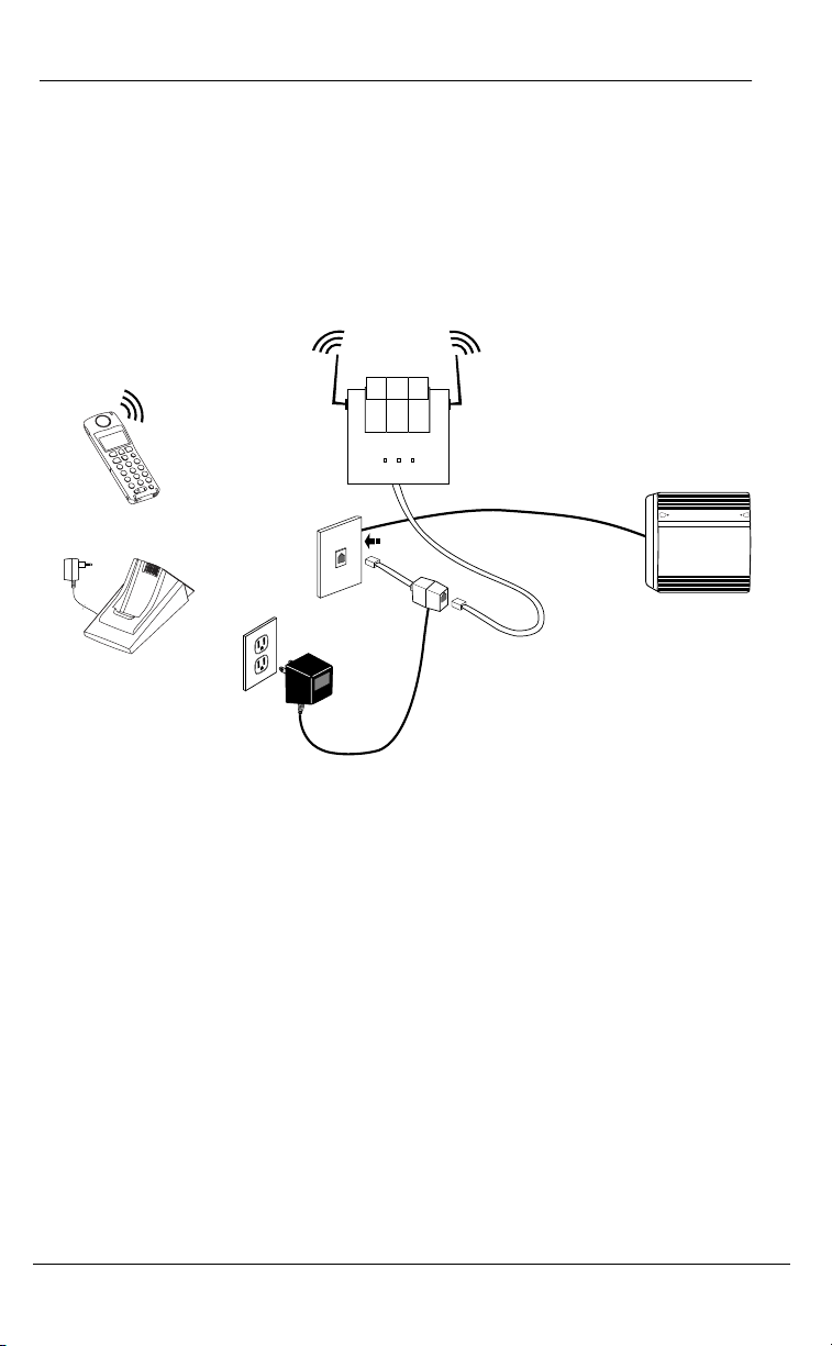
The CM-16 consists of a base station, wireless handset and a charging base
stand. The following diagram provides an overview of the installation of the
product using the power supply provided. Detailed installation
instructions are provided below.
NOTE: Your System Administrator must be aware that the CM-16 emulates the
M2616 in order to correctly configure the switch/communications server
software to allow this phone to operate.
Base Station
CM-16 Handset
Meridian®
Charging Cradle
INSTALLATION
Base Station Location
The CM-16 base station has three LED indicators that provide operational
and installation diagnostic feedback. Please see “APPENDIX A” on page 25
for a detailed chart of LED signals and their meaning.
The base station can be placed on a flat surface or be wall mounted.
For optimum range performance, wall mounting is recommended.
Location of the base station can have significant impact on performance.
It is recommended that the base station be located:
• Away from metal objects such as filing cabinets, metal blinds or other
metal support structures
• Away from other electronic devices such as CRT’s, desktop computers and
other cordless products
• As high as possible with the antennas pointing up in a vertical position.
• The antenna used for the base station transmitter must be installed to
provide a separation distance of at least 20 cm from all persons.
4 Model CM-16 User Guide
Page 8
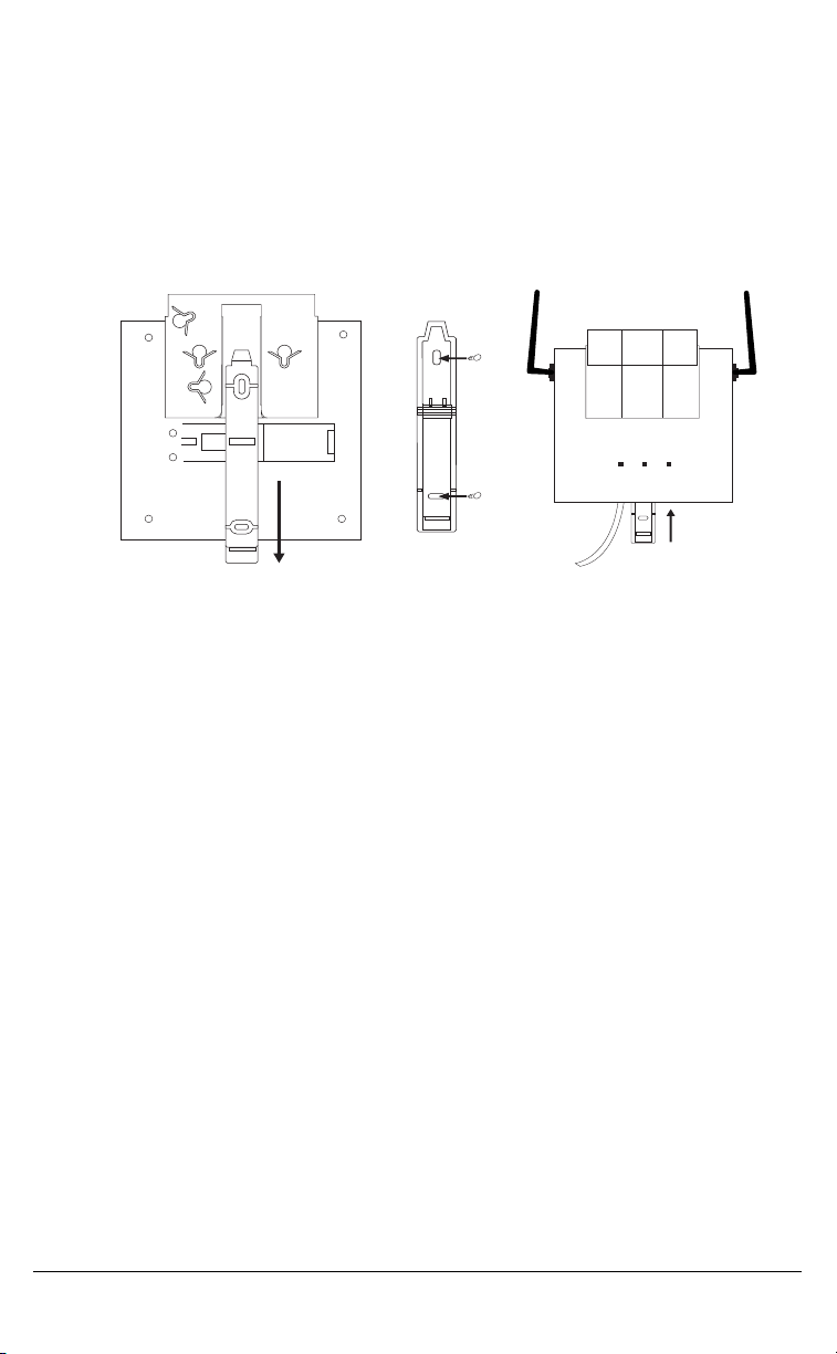
Base Station Wall Mounting
To wall mount the base station:
• Locate the wall mounting strip located on the back side of the base station
• Slide the strip out from the base station (Fig A)
• Turn the strip around and secure firmly to the wall using the screws
supplied (Fig B)
• Plug the line cord into the jack on the unit
• Slide the base station over the strip until it clicks into place (Fig C)
INSTALLATION
Figure A
The installation process is divided into three sections A, B, and C.
If you follow the steps in order, the Handset and Base Unit will properly
synchronize with the M1 2616 port. At this time per Figure 2, prepare
the handset by placing the battery cover and the battery near the handset
so you can connect it quickly in step B5.
Figure B
Figure C
Configure the 2616 Port and wall jack
If you have not already configured and verified a 2616 port, do so now.
The Base Unit will not operate unless connected to a working M1 circuit and
the handset won’t work or even charge the battery properly unless the Base
Unit is operational first.
Base Unit Connections
The Base Unit must be connected to a known working M1 port configured for
a 2616 wired set. Where possible, verify the port and key assignments by
using a 2616 set before connecting the CM-16 to that jack.
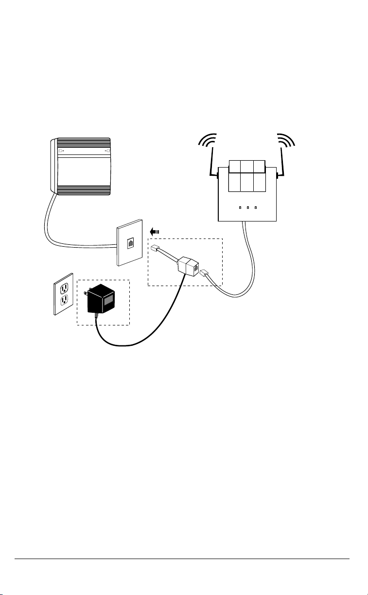
Refer to Figure 1 and connect the components in this order.
1. Plug one end of the 6 conductor cord (supplied) to the Antenna Unit
2. Plug the other end of the 6 conductor cord into the jack on the Power
Adapter Assembly
In the next two steps certain LEDs on the Base Unit should light up, so watch
for the appropriate LED response.
Model CM-16 User Guide 5
Page 9
r
3
3. Plug the short 2 conductor line cord tail of the Power Adapter Assembly
into the 2616 Jack. When a working port is detected and the polarity
is correct (pin 3+ and pin 4- ), the center LED will blink and the left LED will
turn on steady. If both LEDs are not indicating as described, stop the
installation and verify the M1 port is working at the intended jack with a
2616 set. Next, verify all modular cord connections to this point are correct
and making good contact. When both LEDs are indicating properly,
continue at step 4.
Figure 1 CM-16 Base Unit Connections
Base Unit
M1 PBX
Non-switched
AC Outlet
2616 Jack
Xfer
Line Cord
Plug
Power Adapter
6 Conductor
Line Cord
Jack
Pins 1 &6 carry
power form adapte
Pins 3 &4 carry
M1 circuit (pin
Assembly
INSTALLATION
4. Plug the power adapter transformer (Xfmr) into a non-switched 120V
AC outlet. The right LED will blink for about 40 seconds as the Base Unit
scans for its Handset. This indicates the radio circuit has been properly
powered. Go to step 5 to link the handset. If the right LED doesn’t blink,
verify the AC outlet is working and that the power adapter prongs fit snugly
in the outlet. Try another outlet just to be sure. Once the right
LED is blinking, continue at step 5.
5. While the Base Unit is scanning (right LED blinking), connect the battery to
the handset. Place the battery in the compartment and slide the door
closed. The handset should initialize and remain powered for a couple of
minutes, enough time to link with the Antenna Unit and allow you to place a
test call. Watch the handset display. As the handset initializes, two icons
will appear in the top left corner. The left icon is the battery symbol and the
internal bars of the icon show the remaining charge. The other important
icon that must appear is the Antenna just to the right of the battery icon.
When the Antenna icon appears, place a test call.
6 Model CM-16 User Guide
Page 10
e
Place a test call…
From another M1 station, call this DN and answer the call by pressing the
Handset Button (to the left of the ∂ button). Verify two way transmission
and hang up by pressing the button to the right of the ∂ button.
Figure 2 Handset Preparation
Handset
(face down)
INSTALLATION
Keep the Battery
Near the handset
and don't connect
it until Step 5
5
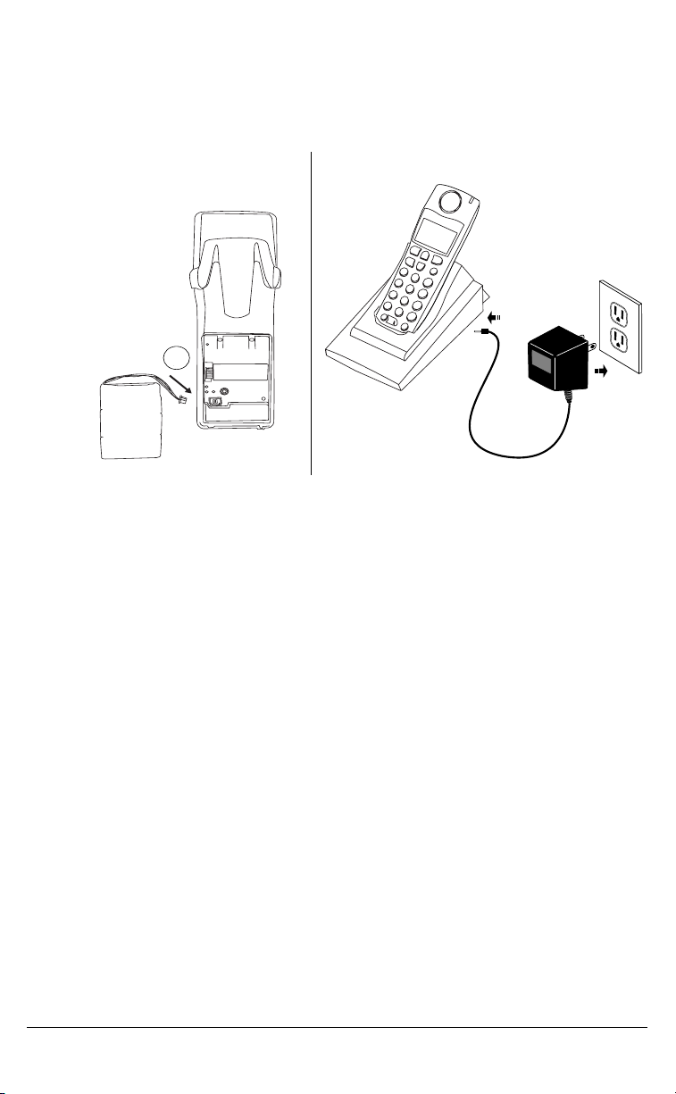
Figure 3 Charger Preparation
Charging Cradle
Refer to Figure 3.
1. Plug the modular cord of the “cradle power adapter” into the jack on
the bottom of the cradle. Route the cord through the retaining tabs of
the molded cord slot. Verify the cradle rests on all four feet and
doesn’t wobble.
2. Plug the transformer into a known working non-switched AC outlet and
place the handset, face up in the charging cradle. There is no power light
on the cradle. However, once the handset is placed in the cradle, the
battery icon will blink indicating the battery is being charged. Should the
icon not blink, check the battery compartment cover to ensure it is properly
closed. If the handset does not easily slide into the charging cradle, the
battery compartment cover is likely not installed correctly.
The Handset (battery) needs to be charged at least 6 hours before use.
Non-switch
AC Outlet
Belt Clip
To install the belt clip, snap one arm of the clip into the slot on the side of
the handset and then slide the other arm into the slot on the other side of the
handset until it snaps into place.
Model CM-16 User Guide 7
Page 11

Using a Headset with your Telephone
The CM-16 accepts headsets through the jack on the bottom of the
handset. Contact your telephone equipment retailer or distributor
to purchase a compatible headset. Customers should read and observe
all safety recommendations contained in headset operating guides
when using any headset.
Battery Status Icons
The display provides “at a glance” information on the handset battery
dcba
f
NOTE: The handset is designed to recharge the batteries automatically, when
required and placed on the charger stand. The battery icon will not flash
and the handset does not charge every time it is placed on the stand. If a
defective battery is replaced, then the battery Icon is not identified until the
new battery is charged for at least 2 minutes.
The bars indicate the battery charge level — 4 for full,
needs recharging when only 1 bar appears.
The bars will flash when the battery is being
recharged on the charger stand.
INSTALLATION
8 Model CM-16 User Guide
Page 12

CM-16 HANDSET KEY FUNCTIONS
1
2
3
11
4
5
6
7
8
CM-16 HANDSET KEY FUNCTIONS
9
16
10
5
12
13
14
16
15
17
Model CM-16 User Guide 9
Page 13

Function # Function Description
1 Receiver
2 Volume key
• During Ringing: Adjusts ringer volume
• During a call: Adjusts receiver volume
• During text mode (not in a call): Moves cursor right/left
3 Display
4 Features ƒƒƒƒ Key List
• Access key to the M1 Feature key list
• Scrolls up when in the various lists
• Add a space during editing
5 Softkeys
• Activates feature or option shown on the display above the
keys
6 Call key åå
• Used to obtain dial tone
• Also used as a Hold key
7 Mute ´´´´ key
• When used, prevents the caller from hearing you
8 Headset jack
9 Status Light
10 Release ∫∫∫∫ key
• To end calls and go on hook
• Exits Menu and the various lists.
11 Menu µµµµ key
• Access key to the different Options
• Scrolls down when in the various lists.
• Used as Backspace during editing
12 Redial ®®®® key
• Displays the last 10 numbers dialed
13 Charging jack
14 Charging contacts
15 Microphone
åå
CM-16 HANDSET KEY FUNCTIONS
10 Model CM-16 User Guide
Page 14

SCREEN
Screen Display
The screen display on the CM-16 provides five lines, 15 characters per
line of display area. Pressing any key will light up the display if the Backlight
option is On.
SCREEN
The display provides a variety of information, using text or icons, pertaining to
set status, including battery strength, reception range and selected
settings. Caller information, option menus, instructions, time and date and
general information about calls in progress may also appear.
In addition, at the bottom of the screen display, softkey functions will appear.
These functions or options change based on activity and can be activated by
pressing the appropriate key just below the display. For M1 functions, the
screen can display functions that are activated by pressing the softkey.
See the “FEATURES LIST” on page 16 of this guide for more information.
NOTE: Whenever the display indicates Use Ω¥ to view use the ç key to scroll
up and the
µ key to scroll down.
Screen Icons
Battery Strength
a
m
h
∑ Message Waiting
p
c
4 bars for battery full and the bars
flash when charging
Reception Range
Indicates that the handset is within range of the Base Station
and that the Base Station is powered.
Call in progress
Indicates that you are off hook
Indicates a message waiting
Vibrate
Vibrate activated
* This symbol indicates that vibrate is active. The difference
between vibrate and silent alert is that the phone will also
ring in vibrate mode, but will not in silent alert mode.
Directory
Directory, which can store up to 50 names and numbers in
alphabetical order. Note that the Directory Softkey can be
overwritten by a feature key during a call. The directory
softkey can always be accessed from within the options list.
Model CM-16 User Guide 11
Page 15

Ringer Volume
This Icon appears when the phone is not in use to indicate the
ringer volume level. As the ringer volume level is increased,
¬b
lb
from off to high, the box will go from empty to fully black.
This icon does not appear when silent alert is activated.
The bell icon and the vibrate icon can be present at the same
time. This means both the vibrate and audio alerters are
active. If the vibrate icon is shown, that means the phone is
in silent alert mode. If just the bell is displayed, then the
phone is in normal alert mode with only the audible alert
active.
Receiver Volume
This Icon is available only when the phone isOff hook.
Displays the receiver audio volume from low to high with the
box gradually filling up as the volume level is increased.
Screen Prompts
Display Message Description
Microphone mute Indicates when the Mute button has been Activated
Out of range Appears briefly when pressing a key if out of range
of the base station
Check Line Cord Will appear if the line cord is not properly connected
to the base station.
SCREEN
12 Model CM-16 User Guide
Page 16

MAKING AND ANSWERING CALLS
To make a call:
Press the å key to obtain dial tone and use the Keypad to dial the number
OR
Predial the number first using the Keypad. The number, as entered, will
appear on the display. If the number is correct, press the å key to dial the
number. If number is incorrect use the ∂ key or press down on the volume
key to erase digits from right to left.
If you need to add a pause to a number (for example, between a telephone
number and an access code) press the PauseKey softkey to insert a 2 second
pause into the number.
Calls can also be made directly from the Directory. See the “DIRECTORY” on
page 22 for further information.
To end a call:
Press ∫ key
OR
Return the handset to the charging cradle.
To answer a call:
Press the å key to answer an incoming call or lift the handset out of the
charging cradle.
Redial
To redial the last 10 numbers:
When on hook
• Press ® key, and use the ç and the ∂ keys to scroll up and down through
the list of the last ten numbers dialed
MAKING AND ANSWERING CALLS
• Press the å key to dial the selected number or press the Line softkey to
select an outgoing line and the Select softkey and the selected number will
automatically be redialed
When off hook
• Press ® key and the last number dialed will automatically be redialed.
In addition to redialing the last 10 numbers, the CM-16 allows
redialed numbers to be deleted from the redial list or saved to the
Directory, while on hook.
To add a redialed number to the directory:
• Press ® key, and use the ç and the ∂ keys to scroll up and down through
the list of the last ten numbers dialed.
• Once the selected number appears on the display, press the Options
softkey — the display shows Save 4Directory and s=Next
• Press the Select softkey. If there is no name associated with the
Model CM-16 User Guide 13
Page 17

number, the display will prompt, to enter a name to save the entry.
Use the instructions in the section Adding a Name and Number to the
Directory to save the entry in the Directory. If there is a name associated
with the number it will automatically save it to the directory and briefly
indicate item saved.
To delete an entry in the Redial list:
• Press ® key, and use the ç and the ∂ keys to scroll up and down through
the list of the last ten numbers dialed
• Once the selected number appears on the display, press the Options soft-
key and the ∂ key once — the display shows Delete and s=Next
• Press the Select softkey. The display will show Delete again to
erase this item.
• Press the Delete softkey to erase the entry. Display shows Item erased.
You can return to the main display any time by pressing the ∫ key.
Hold Function
To place a call on hold, press the å key. To take a call off hold, press the
å key again.
Mute Key
Use the mute key when you want to be able to hear a caller but have
them not hear you. Press the ´ key to mute the handset. Press the ´ key
again to disengage mute.
MAKING AND ANSWERING CALLS
Alerter Tones
The CM-16 uses tones to provide information as follows:
Low Battery one tone every three minutes
Out of Range whenever handset loses connection to base station
Check Line
Cord
Whenever you try to establish a link with the base station
and the DC power is not plugged in and/or the line cord is
not plugged into the base.
Volume Control
The volume key, located on the side of the handset, controls both the receiver
and ringer volume.
NOTE: The volume key can also be used to adjust the right/left cursor to add
spaces or to erase characters on the display when editing or creating
names, key labels etc.
To adjust the receiver volume:
• While on a call, press the top of the key to increase the receiver volume and
press the bottom of the key to decrease the volume. The receiver volume
icon on display will indicate the current volume level. In absence of a PBX,
the receiver volume returns to the default setting after each call. However,
14 Model CM-16 User Guide
Page 18

the PBX directive can direct the handset default to the volume.
To adjust the ringer volume:
• When the handset is not being used for a call, press the top of the key
to increase the ringer volume and press the bottom of the key to decrease
the ringer volume. The handset ringer will sound on each adjustment to
reflect the new setting and the ringer volume icon on display will also show
the current level chosen.
Status Light
The green LED light on the handset indicates the following conditions:
Incoming call
Handset muted flashes rapidly Features activated
flashes rapidly
Call on hold
(only while on hook) /
message waiting
MAKING AND ANSWERING CALLS
solid green
solid green
Model CM-16 User Guide 15
Page 19

FEATURES LIST
There are 14 Meridian features available through the CM-16. The features
list can be accessed through the Feature ƒ key of the CM-16. When scrolling
through the features list, a darker scroll bar highlights the feature that can be
selected. If the Meridian features are labeled instead of pre-programmed
and identified on handset, the features list on the CM-16 menu display will be
identified by item numbers from 00 to 14 with no text (example <09>) Note
that Meridian Key 07 and 15 features are not available on the CM-16.
Also, the first key (00) in the list will always be the primary DN.
• Each feature can be labeled manually through the Edit option. See the
“Key Label “ option in this guide for detailed labeling instructions.
• The 4 indicates that the feature is activated or flashing during
the program state.
• To activate one of the features press the Select Softkey.
To cancel an activated M1 feature key, press the Cancel Softkey or ∫ key to
end the call.
See your system administrator, M2616 Quick Reference guide or
visit the Nortel Networks website for further information on Meridian
features available.
FEATURES LIST
16 Model CM-16 User Guide
Page 20

OPTIONS
To access the options list:
1. Press the
indicate
2. There are ten options that can be accessed by either scrolling to
the option or by using the keypad to dial the option number as per
OPTIONS
the table below.
µ key when the phone is not in use — the display will
Use ¥Ω to view. Use the ç and ∂ keys for scrolling.
Option # Options list
1 Language
2 Key label
3 Ring tone
4 Custom name
5 Timer Off
6 Vibrate Off
7 Hset pairing
8 Key lock Off
9 Backlight Off
10 Silent Alert Off
NOTE: The Menu and Options display revert to the regular idle mode display
if no action/activity is initiated within 20 seconds.
Press ∫ key to quit at any time and to return to the main idle display screen.
Language
The CM-16 offers a choice of English, French and Spanish display
languages.
The default language setting is English. The language display in use is always
identified with a check mark.
To change the display language, follow the display menu prompts using
the two softkeys as required to change, cancel or select a language option.
The display will always show —confirmed— when the selection is changed.
Pressing the Cancel softkey will return you to the previous display.
Pressing the ∫ key will return you to the main idle display screen.
Model CM-16 User Guide 17
Page 21

Key label
The Key label option gives access to the display text associated with the 14
Meridian features that can be programmed with to CM-16 handset.
Text to identify a specific feature can be added, modified or deleted or all
feature key text can be deleted at once. Labels can have up to 14
characters.
To edit key label text
Press the Change softkey from the key label display
• At the Edit display screen, press Select softkey — this will display the
key label 00
• Use the scroll keys to find the feature key desired
• Press the Edit softkey
• Use the keypad to type out a new label or use the scroll keys ç and ∂ to
move the cursor to the desired display position or to erase text. (See
“Entering Letters and Characters” on page 22in the Directory portion of
this guide for additional details regarding adding a name using the keypad)
• The ChCase softkey changes the screen text between Upper and Lower
case
• The Save softkey saves changes made
Use the ∫ key at any time to exit the option menu.
NOTE: In editing mode, the Volume Bar can be used in place of the ( ç and
∂) keys to control the screen cursor
• Press the Lower end volume bar for Backspace/Erase
• Press the Higher end volume bar to add a Space
To delete a single key label
• At the Edit display screen: Press the Change softkey from the key label
display
• Press Select softkey — this will display the key label 00
• Use the scroll keys to find the feature key desired
• Press Delete to delete the text associated with the feature
To delete all feature label text
• Press the Change softkey from the key label display
• Press the ∂ key to move to the Delete All option display
• Press Select softkey — display indicates Press delete to confirm
• Press Delete softkey to delete all labels
OPTIONS
18 Model CM-16 User Guide
Page 22

Ring Tone
The CM-16 offers the choice of four different ring tones.
To change the ring tone, follow the display menu prompts using the two
softkeys as required to change, cancel or select a ring tone. Each of the four
ring tones can be heard prior to selection. The display will always show —
confirmed— to indicate when a selection has been made.
Pressing the Cancel softkey returns you to the options list.
OPTIONS
Pressing the ∫ key returns you to the main idle display screen.
Custom Name
This option allows a name or extension number etc. to be added/edited and
displayed in idle mode. In a multi-handset environment, this is an ideal
option to personalize each handset to its user or extension number.
From the Custom name option display, press the Change softkey and then
the Edit softkey. If an existing custom name already appears on the display,
the Delete softkey is also shown and can be used to delete a custom name.
• Use the keypad to type out a new label or use the scroll keys ç and ∂
to move the cursor to the desired display position or to erase text.
(See “Changing entries in the Directory” on page 23 in the “Directory” for
additional details.)
• The ChCase softkey changes the screen text between upper and lower case
• The Save softkey saves changes made
Pressing the ∫ key returns you to the main idle display screen.
NOTE: In editing mode, the Volume Bar can be used in place of the ( ç and ∂ )
keys to control the screen cursor
• Press the Lower end volume bar for Backspace/Erase
• Press the Higher end volume bar to add a Space
Call Timer
The duration of calls can be displayed by using this option. By default, the
Call Timer option is always Off.
To turn the timer on, press the Change softkey and the display will indicate
Timer On and –confirmed- and will quickly return to the previous menu
display.
Pressing the ∫ key will return you to the main idle display screen.
Vibrate
The Vibrate option allows the CM-16 handset to signal an incoming call by
vibrating as well as ringing. By default, this option is always Off.
To enable this feature, press the Change softkey and the display will
indicate Vibrate On and-confirmed- and will quickly return to the previous
menu display.
Model CM-16 User Guide 19
Page 23

Once the Vibrate is On, the p is shown beside the ringer icon on the top
right line of the display.
Pressing the ∫ key will return you to the main idle display screen.
Handset Pairing
The Handset Pairing option provides flexibility by allowing any CM-16 handset
to work with any CM-16 base station. Each handset is factory programmed to
work only with the base station shipped with the product.
When using this option, be sure to keep the handset at least a few feet away
from the base station. The handset does not need to be placed right in front
of the base station when pairing and may not, in fact, be able to pair if too
close to the base station.
To program the handset to work with another CM-16 base station in this
option, press the Change softkey and the display will indicate Attempting
pairing. If successful, the display will indicate Pairing successful. If the
pairing does not occur, the display will indicate Pairing failed Try again.
Pressing the ∫ key will return you to the main idle display screen.
Key Lock
The key lock option enables the user to lock the keypad keys. This prevents
accidental activation of the phone while carrying it, putting in a pocket etc.
To lock the keys from the key lock option page:
• Press Change softkey to turn Key lock ON or Off. The screen will display
Key lock On or Key lock Off -confirmed-
Pressing the ∫ key will return you to the main idle display screen.
NOTE: You can active the Key Lock Off or On by pressing only the µ key and then
the
≠ asterisk key.
OPTIONS
Backlight
The Backlight option enables the user to have the display diffuser lighted
or not when a keypad key is pressed. Press Change softkey to turn Backlight
ON or Off.
Once the Backlight option is chosen, the screen will display Backlight On
or Backlight Off -confirmed-
20 Model CM-16 User Guide
Page 24

Silent Alert
The Silent Alert option will activate an internal hardware vibrator
instead of a regular ringer during an incoming call. By default, the Silent Alert
is automatically set to Off.
To activate Silent Alert from the option display:
• Press Change softkey to turn alert On or Off. The display will show
–confirmed- and the handset will vibrate if the alert has been turned on
OPTIONS
Once the Alert is On, the p is shown on the Top line of the display.
NOTE: You can active or deactivate the Silent alert by pressing only the ∂ key and
then the
NOTE: The Ringer Icon does not appear on the display when the Silent alert is On.
– key.
Model CM-16 User Guide 21
Page 25

DIRECTORY
The directory can store up to 50 names and numbers, which are displayed in
alphabetical order. If no name is entered, the entries are sorted by number,
at the beginning of the directory.
Adding a name and number to the Directory
1. Press Directory c softkey
2. Press Add softkey. Display prompts Enter number
3. Enter the number using the keypad. You can enter up to 24 digits.
Hyphens will be automatically added. If you need to enter a pause
(between your voice mail number and password, for example)
press the PauseKey softkey and the pause icon will appear. To erase
a digit, use the ∂ key or press the bottom of the volume bar.
4. Press the Save softkey. The display will prompt Enter name. If no
name is to be used for this directory entry, press the Save softkey
again, the display will show Item saved
5. Enter a name using the letters on the dial pad. The name can have
up to 15 characters, including spaces. See the section Entering
Letters and Characters for more details regarding entering text on
display.
To erase a letter or to add a space use the ç and ∂ keys or the volume bar to move the screen cursor position.
6. Press the Save softkey. The display will show Item saved.
DIRECTORY
Pressing the ∫ key will return you to the main idle display screen. If this key
is pressed before the item is saved, it will not be saved.
NOTE: Names and numbers can also be copied into the Directory from the Redial
list. See the “Redial” on page 13 for additional details.
Entering Letters and Characters
You can enter characters using the telephone’s dial pad. To enter a letter,
press the key with that letter on it. If the letter is the second one on that key,
press the key twice. For example, to enter the letter “r”, press the 7 key three
times. The cursor will then advance to the next space.
To change the case of a letter, press the ChCase softkey and then enter the
letter. By default, the first letter of a word or name will be capitalized and the
letters following will be lower case.
Special characters are entered by pressing the 1 key. Characters will appear
in this order: , - ‘ & . ()1
22 Model CM-16 User Guide
Page 26

Finding entries in the Directory
1. Press Directory c softkey
2. Use the ç and ∂ keys to scroll up and down one listing at a time OR
use the dial pad keys to identify entries starting with a certain
letter. For example, to find directory entries starting with the letter
“S”. press the 7 key four times. The first entry will appear. If there
are more directory listings using the letter “S”, you must type in the
second letter of the name.
DIRECTORY
Dialing from the Directory
1. Press Directory c softkey
2. Find the entry you wish to call in the Directory
3. Press the å key to dial the number or use the Line softkey, where
available, to use a different line to place the call
Changing entries in the Directory
1. Press Directory c softkey
2. Find the entry you wish to change in the Directory
3. Press Options softkey
4. Press ∂ key once. Display shows Edit and s=Next
5. Press Select softkey. The current stored telephone number for
the directory entry appears on the display. Use the ∂ key or press
the bottom of the volume bar to erase a number and use the keypad
to correct the telephone number.
6. Press the Save softkey to save the change to the phone number.
The display then prompts you to Enter name. If required, change
the name using the instructions found in the “Adding a name and
number to the Directory” on page 22 section of this guide.
7. Press the Save softkey to save the revised Directory entry. Will dis-
playItem saved.
Pressing the ∫ key will return you to the main idle display screen.
Model CM-16 User Guide 23
Page 27

Deleting an entry in the Directory
1. Press Directory c softkey
2. Find the entry you wish to delete in the Directory
3. Press Options softkey
4. Press ∂ key twice. Displays Delete and s=Next
5. Press Select softkey. Displays Press Delete to confirm
6. Press the Delete softkey. Displays Item erased
Pressing the ∫ key will return you to the main idle display screen.
Deleting all entries in the Directory
1. Press Directory c softkey
2. Press Delete softkey. Display shows Press Delete to erase all
3. Press the Delete softkey. Display shows All items erased
DIRECTORY
24 Model CM-16 User Guide
Page 28

APPENDIX A
The CM-16 base station has three LED indicators. Refer to the following
diagram to correctly relate the LED designation to the information supplied in
this Appendix.
APPENDIX A
Left Center Right
Each of these LED’s provides system status information as follows:
Left LED
Led State Meaning
Solid Off Base is NOT supplied switch line power.
Solid On Base is supplied switch line power
The left LED on the CM-16 Base is currently tied to Vcc (Meridian switch
power).
Center LED
The center LED is controlled by the base MCU and indicates Meridian
switch communications status.
Led State Meaning
Flashing ~2Hz Base properly communicating with the switch.
Solid Off Base has no line power.
(Same as solid off for left LED)
Flash once every 2
seconds / Solid On
Base is receiving power from the switch but
is cannot communicate properly.
Model CM-16 User Guide 25
Page 29

Right LED
The right LED indicates radio status, both radio link activity and
registration activity.
Led State Meaning
Solid Off There is no radio link and the base is not
attempting to pair.
Solid On The base is currently in a radio link state with a
handset
Flashing Rapidly Base is attempting a pairing with a handset (enters
this mode at power up in addition to pairing button
press)
APPENDIX A
26 Model CM-16 User Guide
Page 30

LIMITED WARRANTY
Aastra Telecom warrants this product against defects and malfunctions
during a one (1) year period from the date of original purchase. If there is a
defect or malfunction, Aastra Telecom shall, at its option, and as the exclusive
remedy, either repair or replace the telephone set at no charge, if returned
within the warranty period.
If replacement parts are used in making repairs, these parts may be
refurbished, or may contain refurbished materials. If it is necessary to
replace the telephone set, it may be replaced with a refurbished telephone of
the same design and color.
If it should become necessary to repair or replace a defective or
malfunctioning telephone set under this warranty, the provisions of this
warranty shall apply to the repaired or replaced telephone set until the
expiration of ninety (90) days from the date of pick up, or the date of
shipment to you, of the repaired or replacement set, or until the end of the
original warranty period, whichever is later. Proof of the original purchase
LIMITED WARRANTY
date is to be provided with all telephone sets returned for warranty repairs.
Exclusions
Aastra Telecom does not warrant its telephone sets to be compatible with
the equipment of any particular telephone company. This warranty does
not extend to damage to products resulting from improper installation
or operation, alteration, accident, neglect, abuse, misuse, fire or natural
causes such as storms or floods, after the telephone is in your possession.
Aastra Telecom shall not be liable for any incidental or consequential
damages, including, but not limited to, loss, damage or expense directly or
indirectly arising from the customers use of or inability to use this telephone,
either separately or in combination with other equipment. This paragraph,
however, shall not apply to consequential damages for injury to the person in
the case of telephones used or bought for use primarily for personal, family or
household purposes.
This warranty sets forth the entire liability and obligations of Aastra Telecom
with respect to breach of warranty, and the warranties set forth or limited
herein are the sole warranties and are in lieu of all other warranties,
expressed or implied, including warranties or fitness for particular purpose
and merchantability.
Model CM-16 User Guide 27
Page 31

Warranty Repair Services
Should the set fail during the warranty period;
In North America, please call 1-800-574-1611 for further information.
Outside North America, contact your sales representative for return
instructions.
You will be responsible for shipping charges, if any. When you return this
telephone for warranty service, you must present proof of purchase.
After Warranty Service
Aastra Telecom offers ongoing repair and support for this product.
This service provides repair or replacement of your Aastra Telecom product,
at Aastra Telecom's option, for a fixed charge. You are responsible for all
shipping charges. For further information and shipping instructions;
In North America, contact our service information number: 1-800-574-1611.
Outside North America, contact your sales representative.
NOTE: Repairs to this product may be made only by the manufacturer and its
authorized agents, or by others who are legally authorized. This restriction
applies during and after the warranty period. Unauthorized repair will void
the warranty.
LIMITED WARRANTY
28 Model CM-16 User Guide
Page 32

INDEX
A
Appendix A 25
B
Base Station 1
Location 4
Wall Mounting 5
Base Unit 5
Batteries 1
Battery 8, 11, 14
Belt Clip 7
C
Call
redial 13
to answer 13
to end 13
to make 13
Call in progress 11
Charging Cradle 7
Check Line Cord 14
D
Directory 22
Adding a Name and Number
22
Changing entries 23
Deleting all Entries 24
Deleting an Entry 23
Dialing from 23
Entering Letters and Char-
acters 22
Finding entries 23
F
Features List 16
H
Handset 1
Handset and Base Station 1
Headset 8
Hold 14
I
Installation 4
K
Key Functions 10
L
LED
Center LED 25
Left LED 25
Right LED 26
M
Message Waiting 11
Mute 14
O
Options
Backlight 20
Call Timer 19
Custom Name 19
Handset Pairing 20
Key label 18
Key Lock 20
Language 17
Ring Tone 19
Silent Alert 21
Vibrate 19
Out of Range 14
R
Receiver Volume 12, 14
Reception Range 11
Regulatory Information 3
Ringer Volume 12, 15
Page 33

S
Safety Information 1
Screen
Display 11
Icons 11
Screen Prompts 12
T
Tones 14
V
Vibrate 11
Volume
Receiver 14
Ringer 15
Volume Control 14
W
Wall jack 5
INDEX
Page 34

If you’ve read this owner’s manual and still have problems, please visit our website at www.aastra.com
or call 1-800-574-1611 for technical assistance.
© Aastra Telecom Inc. 2005 41-0071-00 Rev 03
 Loading...