

Page 1
H3/V3 Series
Horizontal and Vertical Indoor Air Handling Units
Installation, Operation
If the information in this manual is not
followed exactly, a fire or explosion
may result causing property damage,
personal injury or loss of life.
FOR YOUR SAFETY
Do not store or use gasoline or other
flammable vapors and liquids in the
vicinity of this or any other appliance.
WARNING
WARNING
QUALIFIED INSTALLER
Improper installation, adjustment,
alteration, service or maintenance
can cause property damage,
personal injury or loss of life. Startup
and service must be performed by a
Factory Trained Service Technician.
A copy of this IOM should be kept
with the unit.
WARNING
& Maintenance
Page 2

Page 3

Table of Contents
Safety .............................................................................................................................................. 6
H3/V3 Base Model Description .................................................................................................... 10
General Information ...................................................................................................................... 16
Codes and Ordinances ............................................................................................................... 16
Receiving Unit ........................................................................................................................... 17
Storage ....................................................................................................................................... 17
Direct Expansion (DX) Systems ............................................................................................... 17
Wiring Diagrams ....................................................................................................................... 18
Condensate Drain Pans .............................................................................................................. 18
Installation..................................................................................................................................... 18
Locating the Unit ....................................................................................................................... 19
Lifting and Handling the Unit ................................................................................................... 22
Electrical .................................................................................................................................... 22
Duct Connection ........................................................................................................................ 25
Condensate Drain Piping ........................................................................................................... 25
Heating Coils ............................................................................................................................. 26
Chilled Water Coil .................................................................................................................... 26
Electric Preheat ......................................................................................................................... 26
Refrigerant Piping ..................................................................................................................... 26
Determining Refrigerant Line Size ........................................................................................... 28
Startup ........................................................................................................................................... 32
Supply Fans ............................................................................................................................... 32
Fan Air Flow Adjustment .......................................................................................................... 32
Filters ......................................................................................................................................... 34
Adjusting Refrigerant Charge ................................................................................................... 34
Operation....................................................................................................................................... 37
Electric Heating Operation ........................................................................................................ 37
Steam or Hot Water Preheating Operation ................................................................................ 37
Chilled Water or Non-Compressorized DX Cooling Operation ............................................... 37
Modulating Electric Preheat ...................................................................................................... 37
Maintenance .................................................................................................................................. 37
DX Cooling ............................................................................................................................... 37
Condensate Drain Pans .............................................................................................................. 37
E-Coated Coil Cleaning ............................................................................................................ 38
Supply Fans ............................................................................................................................... 39
Filter Replacement .................................................................................................................... 39
Replacement Parts ..................................................................................................................... 40
AAON-Longview Customer Service Department .................................................................... 40
Filter Information .......................................................................................................................... 41
Refrigerant Piping Diagrams ........................................................................................................ 52
H3/V3 Series Startup Form ........................................................................................................... 64
Maintenance Log .......................................................................................................................... 69
Literature Change History............................................................................................................. 70
3
Page 4

Index of Tables and Figures
Tables:
Table 1 - H3 and V3 Series Clearances ........................................................................................ 19
Table 2 - Control Wiring............................................................................................................... 24
Table 3 - Drain Trap Dimensions ................................................................................................. 26
Table 4 - Acceptable Air-Cooled Refrigeration Circuit Values ................................................... 35
Table 5 - Acceptable Water-Cooled Refrigeration Circuit Values ............................................... 35
Table 6 - R-410A Refrigerant Temperature-Pressure Chart ......................................................... 36
Table 7 - H3 Series A Cabinet Pre Filters..................................................................................... 41
Table 8 - V3 Series A Cabinet Pre Filters..................................................................................... 41
Table 9 - H3 Series B Cabinet Pre Filters ..................................................................................... 42
Table 10 - V3 Series B Cabinet Pre Filters ................................................................................... 42
Table 11 - H3 Series C Cabinet Pre Filters ................................................................................... 43
Table 12 - V3 Series C Cabinet Pre Filters ................................................................................... 43
Table 13 - H3 Series D Cabinet Pre Filters................................................................................... 44
Table 14 - V3 Series D Cabinet Pre Filters................................................................................... 44
Table 15 - H3 Series E Cabinet Pre Filters ................................................................................... 45
Table 16 - V3 Series E Cabinet Pre Filters ................................................................................... 45
Table 17 - H3 Series A Cabinet Unit Filters ................................................................................. 46
Table 18 - V3 Series A Cabinet Unit Filters ................................................................................. 46
Table 19 - H3 Series B Cabinet Unit Filters ................................................................................. 47
Table 20 - V3 Series B Cabinet Unit Filters ................................................................................. 47
Table 21 - V3 Series C Cabinet Unit Filters ................................................................................ 48
Table 22 - V3 Series D Cabinet Unit Filters ................................................................................. 48
Table 23 - H3 Series A Cabinet Final Filters ................................................................................ 49
Table 24 - V3 Series A Cabinet Final Filters ................................................................................ 49
Table 25 - H3 Series B Cabinet Final Filters ................................................................................ 49
Table 26 - V3 Series B Cabinet Final Filters ................................................................................ 49
Table 27 - H3 Series C Cabinet Final Filters ................................................................................ 50
Table 28 - V3 Series C Cabinet Final Filters ................................................................................ 50
Table 29 - H3 Series D Cabinet Final Filters ................................................................................ 50
Table 30 - V3 Series D Cabinet Final Filters ................................................................................ 50
Table 31 - H3 Series E Cabinet Final Filters ................................................................................ 51
Table 32 - V3 Series E Cabinet Final Filters ................................................................................ 51
4
Page 5

Figures:
Figure 1 - Lockable Handle .......................................................................................................... 17
Figure 2 – Minimum Clearance Required for Access to Unit (V3 Series plan view) .................. 19
Figure 3 – Minimum Clearance Required for Access to Unit (H3 Series plan view) .................. 19
Figure 4 – H3 Series Platform Suspension Installation ................................................................ 20
Figure 5 – H3 Series Parallel Beam Suspension Installation ........................................................ 20
Figure 6 - H3 Series Unit Orientation ........................................................................................... 21
Figure 7 - V3 Series Unit Orientation ........................................................................................... 21
Figure 8 - Drain Trap .................................................................................................................... 25
Figure 9 - TXV Bulb Position ....................................................................................................... 27
Figure 10 - Supply Fan Banding ................................................................................................... 33
Figure 11 – A/C only piping, AHU above CU ............................................................................. 52
Figure 12 – A/C only piping, AHU below CU ............................................................................. 53
Figure 13 – Modulating hot gas reheat piping, AHU above CU .................................................. 54
Figure 14 – Modulating hot gas reheat piping, AHU below CU .................................................. 55
Figure 15 – Hot gas bypass piping, AHU above CU .................................................................... 56
Figure 16 – Hot gas bypass piping, AHU below CU .................................................................... 57
Figure 17 – Modulating hot gas reheat with hot gas bypass piping, AHU above CU .................. 58
Figure 18 – Modulating hot gas reheat with hot gas bypass piping, AHU below CU.................. 59
Figure 19 – Heat pump piping, AHU above CU .......................................................................... 60
Figure 20 – Heat pump piping, AHU below CU .......................................................................... 61
Figure 21 – Heat pump with modulating hot gas reheat piping, AHU above CU ........................ 62
Figure 22 – Heat pump with modulating hot gas reheat piping, AHU below CU ........................ 63
R94201 · Rev. A · 140521
(ACP J00188)
5
Page 6
Attention should be paid to the following statements:
NOTE - Notes are intended to clarify the unit installation, operation and maintenance.
CAUTION - Caution statements are given to prevent actions that may result in
equipment damage, property damage, or personal injury.
WARNING - Warning statements are given to prevent actions that could result in
equipment damage, property damage, personal injury or death.
DANGER - Danger statements are given to prevent actions that will result in equipment
damage, property damage, severe personal injury or death.
ELECTRIC SHOCK, FIRE OR
EXPLOSION HAZARD
Failure to follow safety warnings
exactly could result in dangerous
operation, serious injury, death or
property damage.
Improper servicing could result in
dangerous operation, serious injury,
death or property damage.
Before servicing, disconnect all
electrical power to the unit. More
than one disconnect may be
provided.
When servicing controls, label all
wires prior to disconnecting.
Reconnect wires correctly.
Verify proper operation after
servicing. Secure all doors with
key-lock or nut and bolt.
WARNING
Electric shock hazard. Before
servicing, disconnect all electrical
power to the unit, including remote
disconnects, to avoid shock hazard
or injury from rotating parts. Follow
proper Lockout-Tagout procedures.
WARNING
FIRE, EXPLOSION OR CARBON
MONOXIDE POISONING HAZARD
Failure to replace proper controls
could result in fire, explosion or
carbon monoxide poisoning. Failure
to follow safety warnings exactly
could result in serious injury, death or
property damage. Do not store or use
gasoline or other flammable vapors
and liquids in the vicinity of this
appliance.
WARNING
Safety
6
Page 7
VARIABLE FREQUENCY DRIVES
Do not leave VFDs unattended in
hand mode or manual bypass.
Damage to personnel or equipment
can occur if left unattended. When in
hand mode or manual bypass mode
VFDs will not respond to controls or
alarms.
WARNING
GROUNDING REQUIRED
All field installed wiring must be
completed by qualified personnel.
Field installed wiring must comply
with NEC/CEC, local and state
electrical code requirements. Failure
to follow code requirements could
result in serious injury or death.
Provide proper unit ground in
accordance with these code
requirements.
WARNING
During installation, testing, servicing
and troubleshooting of the equipment
it may be necessary to work with live
electrical components. Only a
qualified licensed electrician or
individual properly trained in handling
live electrical components shall
perform these tasks.
Standard NFPA-70E, an OSHA
regulation requiring an Arc Flash
Boundary to be field established and
marked for identification of where
appropriate Personal Protective
Equipment (PPE) be worn, should be
followed.
WARNING
UNIT HANDLING
To prevent injury or death lifting
equipment capacity shall exceed unit
weight by an adequate safety factor.
Always test-lift unit not more than 24
inches high to verify proper center of
gravity lift point to avoid unit damage,
injury or death.
WARNING
ROTATING COMPONENTS
Unit contains fans with moving parts
that can cause serious injury. Do not
open door containing fans until the
power to the unit has been
disconnected and fan wheel has
stopped rotating.
WARNING
Electric motor over-current protection
and overload protection may be a
function of the Variable Frequency
Drive to which the motors are wired.
Never defeat the VFD motor overload
feature. The overload ampere setting
must not exceed 115% of the electric
motors FLA rating as shown on the
motor nameplate.
CAUTION
Failure to properly drain and vent
coils when not in use during freezing
temperature may result in coil and
equipment damage.
CAUTION
7
Page 8
Do not clean DX refrigerant coils with
hot water or steam. The use of hot
water or steam on refrigerant coils
will cause high pressure inside the
coil tubing and damage to the coil.
WATER PRESSURE
Prior to connection of condensing
water supply, verify water pressure is
less than maximum pressure shown
on unit nameplate. To prevent injury
or death due to instantaneous
release of high pressure water, relief
valves should be field supplied on
system water piping.
To prevent damage to the unit, do not
use acidic chemical coil cleaners. Do
not use alkaline chemical coil
cleaners with a pH value greater than
8.5, after mixing, without first using
an aluminum corrosion inhibitor in the
cleaning solution.
CAUTION
WARNING
CAUTION
Do not use oxygen, acetylene or air
in place of refrigerant and dry
nitrogen for leak testing. A violent
explosion may result causing injury or
death.
WARNING
Always use a pressure regulator,
valves and gauges to control
incoming pressures when pressure
testing a system. Excessive pressure
may cause line ruptures, equipment
damage or an explosion which may
result in injury or death.
WARNING
Do not work in a closed area where
refrigerant or nitrogen gases may be
leaking. A sufficient quantity of
vapors may be present and cause
injury or death.
WARNING
Rotation must be checked on all
MOTORS AND COMPRESSORS of
3 phase units at startup by a qualified
service technician. Scroll
compressors are directional and can
be damaged if rotated in the wrong
direction. Compressor rotation must
be checked using suction and
discharge gauges. Fan motor rotation
should be checked for proper
operation. Alterations should only be
made at the unit power connection
CAUTION
8
Page 9
Some chemical coil cleaning
compounds are caustic or toxic. Use
these substances only in accordance
with the manufacturer’s usage
instructions. Failure to follow
instructions may result in equipment
damage, injury or death.
WARNING
Door compartments containing
hazardous voltage or rotating parts
are equipped with door latches to
allow locks. Door latch are shipped
with nut and bolts requiring tooled
access. If you do not replace the
shipping hardware with a pad lock
always re-install the nut & bolt after
closing the door.
CAUTION
PVC (Polyvinyl Chloride) and CPVC
(Chlorinated Polyvinyl Chloride) are
vulnerable to attack by certain
chemicals. Polyolester (POE) oils
used with R-410A and other
refrigerants, even in trace amounts,
in a PVC or CPVC piping system will
result in stress cracking of the piping
and fittings and complete piping
system failure.
CAUTION
1. Startup and service must be performed
by a Factory Trained Service
Technician.
2. The unit is for indoor use only. See
General Information section for more
unit information.
3. Every unit has a unique equipment
nameplate with electrical, operational,
and unit clearance specifications.
Always refer to the unit nameplate for
specific ratings unique to the model you
have purchased.
4. READ THE ENTIRE INSTALLATION,
OPERATION AND MAINTENANCE
MANUAL. OTHER IMPORTANT
SAFETY PRECAUTIONS ARE
PROVIDED THROUGHOUT THIS
MANUAL.
5. Keep this manual and all literature
safeguarded near or on the unit.
9
Page 10
H3/V3 Series Feature String Nomenclature
Model Options
:
Unit Feature Options
GEN SIZE
ORENT
MJREV VLT CORR A1
A2
A3
A4 B1
B2
B3
1A
1B
1C
1D 2 3 4 5A
5B
5C 6A
6B
6C 7 8 9
10
11
12
13
14A
14B
H3
- A R B - 3 - 0 - 1 6 1 C
-
1 2 F : A A B B - 0 C 0 - F T B - 0 G 0 - 0 0 A A A C 0 0
B
A 0 0 0 0 0 0 0 0
15
16
17
18
19
20
21
22
23
BASE MODEL
SERIES AND GENERATION
H3 = Horizontal - Back Intake, Front Discharge
V3 = Vertical - Back Intake, Top Discharge
UNIT SIZE
A = Up to 1,200 cfm
B = Up to 2,000 cfm
C = Up to 4,000 cfm
D = Up to 6,000 cfm
E = Up to 10,000 cfm
UNIT ORIENTATION
R = Right Hand Connections
L = Left Hand Connections
REVISION
A = First Revision
B = Second Revision
VOLTAGE
1 = 230V/1Φ/60Hz
2 = 230V/3Φ/60Hz
3 = 460V/3Φ/60Hz
4 = 575V/3Φ/60Hz
8 = 208V/3Φ/60Hz
9 = 208V/1Φ/60Hz
CORROSION PROTECTION
0 = None
A = Interior Corrosion Protection
H3/V3 Base Model Description
Model Option A: COOLING
A1: COOLING TYPE
0 = No Cooling
1 = R-410A DX Cooling
2 = Chilled Water Cooling
A2: COOILNG ROWS
0 = No Cooling
4 = 4 Row Coil
6 = 6 Row Coil
8 = 8 Row Coil
A3: COOLING STAGES
0 = No Cooling
1 = Single Circuit
2 = Two Circuits - Interlaced Coil
D = Double Serpentine
F = Single Serpentine
H = Half Serpentine
Q = Quarter Serpentine
A4: COOLING FPI
0 = No Cooling
A = 10 fpi
B = 8 fpi
C = 12 fpi
10
Page 11
H3/V3 Series Feature String Nomenclature
Model Options
:
Unit Feature Options
GEN SIZE
ORENT
MJREV VLT CORR A1
A2
A3
A4 B1
B2
B3
1A
1B
1C
1D 2 3 4 5A
5B
5C 6A
6B
6C 7 8 9
10
11
12
13
14A
14B
H3 - A R B - 3 - 0 - 1 6 1 C -
1 2 F : A A B
B
- 0 C 0 - F T B - 0 G 0 - 0 0 A A A C 0 0
B
A 0 0 0 0 0 0 0 0
15
16
17
18
19
20
21
22
23
Model Option B: HEATING
B1: HEATING TYPE
0 = No Heating
1 = Hot Water
3 = Electric Heating
4 = Steam Distributing
B2: HEATING DESIGNATION
0 = No Heating
1 = 1 Row Coil
2 = 2 Row Coil
A = 7 kW (5.3 kW @ 208V)
B = 14 kW (10.5 kW @ 208V)
C = 21 kW (15.8 kW @ 208V)
D = 28 kW (21.0 kW @ 208V)
E = 35 kW (26.3 kW @ 208V)
F = 42 kW (31.5 kW @ 208V)
G = 49 kW (37.0 kW @ 208V)
H = 56 kW (42.0 kW @ 208V)
J = 63 kW (47.3 kW @ 208V)
K = 70 kW (52.5 kW @ 208V)
L = 77 kW (57.8 kW @ 208V)
M = 84 kW (63.0 kW @ 208V)
B3: HEATING STAGES
0 = No Heating
1 = 1 Stage
2 = 2 Stage
3 = 3 Stage
4 = 4 Stage
S = Modulating/SCR Electric
F = Single Serpentine 12 fpi
H = Half Serpentine 12 fpi
Q = Quarter Serpentine 12 fpi
Feature 1: SUPPLY FAN
1A: SUPPLY AIR BLOWER CONFIGURATION
0 = 1 Blower + Premium Eff. Motor
1 = 1 Blower + Premium Eff. Motor + 1 VFD
A = 1 Blower + 1 High Efficiency EC Motor
B = 2 Blowers + 2 High Efficiency EC Motors
1B: SUPPLY AIR BLOWER
1 = 15” Backward Curved Plenum Fan
2 = 15” BC Plenum, 50% Width with Banding
3 = 18.5” Backward Curved Plenum Fan
4 = 18.5” BC Plenum Fan, 70% Width with Banding
5 = 22” Backward Curved Plenum Fan
6 = 24” Backward Curved Plenum Fan
7 = 27” Backward Curved Plenum Fan
8 = 27” BC Plenum Fan, 70% Width with Banding
A = 310 mm Direct Drive BC Plenum Fan
B = 355 mm Direct Drive BC Plenum Fan
C = 450 mm Direct Drive BC Plenum Fan
1C: SUPPLY AIR BLOWER MOTOR
1 = 1 hp - 1760 rpm
2 = 2 hp - 1760 rpm
3 = 3 hp - 1760 rpm
4 = 5 hp - 1760 rpm
5 = 7.5 hp - 1760 rpm
6 = 10 hp - 1760 rpm
B = 1.0 kW (1.34 hp)
C = 1.7 kW (2.28 hp)
D = 3.0 kW (4.02 hp)
E = 5.4 kW (8.00 hp)
1D: SUPPLY BLOWER CONTROL/CONTROL
VENDORS
0 = Standard - Terminal Block
A = Potentiometer Supply Fan Control
B = WattMaster Orion Controls System
C = Field Installed Controls by Others
11
Page 12

H3/V3 Series Feature String Nomenclature
Model Options
:
Unit Feature Options
GEN SIZE
ORENT
MJREV VLT CORR A1
A2
A3
A4 B1
B2
B3
1A
1B
1C
1D 2 3 4 5A
5B
5C 6A
6B
6C 7 8 9
10
11
12
13
14A
14B
H3 - A R B - 3 - 0 - 1 6 1 C - 1 2
F : A A B B -
0 C 0 - F T B
- 0 G 0 - 0 0 A A A C 0 0
B
A 0 0 0 0 0 0 0 0
15
16
17
18
19
20
21
22
23
Feature 2: REFRIGERATION OPTIONS
0 = Standard - None
A = Single Circuit External Hot Gas Bypass
B = Dual Circuit External Hot Gas Bypass
C = Heat Pump
D = Option B + H
E = Options B + J
F = Options C + H
G = Options C + J
H = Modulating Hot Gas Reheat
J = Factory Installed Modulating Hot Gas Reheat
K = Dual Circuit Modulating Hot Gas Reheat +
Option B
L =Factory Installed Dual Circuit Modulating Hot
Gas Reheat + Option B
M = Dual Circuit Modulating Hot Gas Reheat +
Option C
N = Factory Installed Dual Circuit Modulating Hot
Gas Reheat + Option C
P = Option H (Circuit 1) + Option A (Circuit 2)
Q = Option J (Circuit 1) + Option A (Circuit 2)
Feature 3: SPECIAL CONTROLS
0 = Standard - None
A = Constant Volume Controller - CV Cool + CV
Heat
B = Constant Volume Controller with Modulating
Hot Gas Reheat - CV Cool + CV Heat
C = VAV Controller - VAV Cool + CV Heat
D = VAV Controller with MHGR - VAV Cool + CV
Heat
E = Make Up Air Controller - CV Cool + CV Heat
F = Make Up Air Controller with Modulating Hot
Gas Reheat - CV Cool + CV Heat
G = WattMaster Modulating Hot Gas Reheat
Controller
Feature 4: ADDITIONAL CONTROLS
0 = Standard - None
A = Phase and Brownout Protection
B = Return and Supply Air Firestat
C = Return Air Smoke Detector
D = Options A + B
E = Options A + C
F = Options B + C
G = Options A + B + C
Feature 5: MIXING BOX
5A: RETURN AIR DAMPER POSITION
0 = Standard - None
F = Front
L = Left Hand (Front OA Damper Required)
R = Right Hand (Front OA Damper Required)
T = Top (Front OA Damper Required)
5B: OUTSIDE AIR DAMPER POSITION
0 = Standard - None
F = Front
L = Left Hand (Front RA Damper Required)
R = Right Hand (Front RA Damper Required)
T = Top (Front RA Damper Required)
5C: MIXING BOX DAMPER CONTROL
0 = Standard - None
A = 2 Position Actuators
B = Fully Modulating Actuators
C = Fixed Position Dampers
12
Page 13

H3/V3 Series Feature String Nomenclature
Model Options
:
Unit Feature Options
GEN SIZE
ORENT
MJREV VLT CORR A1
A2
A3
A4 B1
B2
B3
1A
1B
1C
1D 2 3 4 5A
5B
5C 6A
6B
6C 7 8 9
10
11
12
13
14A
14B
H3 - A R B - 3 - 0 - 1 6 1 C - 1 2
F : A A B B - 0 C 0 - F T B -
0 G 0 - 0 0 A A A
C 0 0
B
A 0 0 0 0 0 0 0 0
15
16
17
18
19
20
21
22
23
Feature 6: FILTER BOX
6A: PRE FILTER BOX
0 = Standard - None
A = 2” Pleated - 30% Eff. - MERV 8
B = 4” Pleated - 30% Eff. - MERV 8
C = 4” Pleated - 65% Eff. - MERV 11
D = 4” Pleated - 85% Eff. - MERV 13
E = 4” Pleated - 95% Eff. - MERV 14
F = 2” Pleated - 30% Eff. - MERV 8 + 4” Pleated -
30% Eff. - MERV 8
G = 2” Pleated - 30% Eff. - MERV 8 + 4” Pleated 65% Eff. - MERV 11
H = 2” Pleated - 30% Eff. - MERV 8 + 4” Pleated 85% Eff. - MERV 13
J = 2” Pleated - 30% Eff. - MERV 8 + 4” Pleated 95% Eff. - MERV 14
6B: UNIT FILTER
0 = Standard - None
A = 2” Pleated - 30% Eff. - MERV 8
B = 4” Pleated - 30% Eff. - MERV 8
C = 4” Pleated - 65% Eff. - MERV 11
D = 4” Pleated - 85% Eff. - MERV 13
E = 4” Pleated - 95% Eff. - MERV 14
F = 2” Pleated - 30% Eff. - MERV 8 + 4” Pleated -
30% Eff. - MERV 8
G = 2” Pleated - 30% Eff. - MERV 8 + 4” Pleated 65% Eff. - MERV 11
H = 2” Pleated - 30% Eff. - MERV 8 + 4” Pleated 85% Eff. - MERV 13
J = 2” Pleated - 30% Eff. - MERV 8 + 4” Pleated 95% Eff. - MERV 14
6C: FINAL FILTER BOX
0 = Standard - None
A = 2” Pleated - 30% Eff. - MERV 8
B = 12” Cartridge - 65% Eff. - MERV 11
C = 12” Cartridge - 85% Eff. - MERV 13
D = 12” Cartridge - 95% Eff. - MERV 14
E = 2” Pleated - 30% Eff. - MERV 8 + 12” Cartridge
- 65% Eff. - MERV 11
F = 2” Pleated - 30% Eff. - MERV 8 + 12” Cartridge
- 85% Eff. - MERV 13
G = 2” Pleated - 30% Eff. - MERV 8 + 12” Cartridge
- 95% Eff. - MERV 14
Feature 7: FILTER OPTIONS
0 = Standard - None
A = Magnehelic Gauge
B = Clogged Filter Switch
C = Options A + B
Feature 8: COIL COATING
0 = Standard - None
A = E-coated Cooling and Heating Coils
Feature 9: EXPANSION VALVE
0 = None
A = Thermal Expansion Valves
Feature 10: EXPANSION VALVE
CONTROLS
0 = None
A = Standard Control
Feature 11: EXTERNAL PAINT
0 = Standard - None
A = AAON Gray Paint
B = Special Paint
13
Page 14
H3/V3 Series Feature String Nomenclature
Model Options
:
Unit Feature Options
GEN SIZE
ORENT
MJREV VLT CORR A1
A2
A3
A4 B1
B2
B3
1A
1B
1C
1D 2 3 4 5A
5B
5C 6A
6B
6C 7 8 9
10
11
12
13
14A
14B
H3 - A R B - 3 - 0 - 1 6 1 C - 1 2
F : A A B B - 0 C 0 - F T B - 0 G 0 - 0 0 A A
A
C 0 0
B
A 0 0 0 0
0
0 0 0
15
16
17
18
19
20
21
22
23
Feature 12: TONNAGE
0 = Standard - None
A = 2 ton Capacity
B = 3 ton Capacity
C = 4 ton Capacity
D = 5 ton Capacity
E = 6 ton Capacity
F = 7 ton Capacity
G = 8 ton Capacity
H = 10 ton Capacity
J = 14 ton Capacity
K = 17 ton Capacity
L = 22 ton Capacity
M = 25 ton Capacity
N = 30 ton Capacity
P = 31 ton Capacity
Q = 34 ton Capacity
R = 40-45 ton Capacity
S = 50-55 ton Capacity
T = 63 ton Capacity
Feature 13: ADDED OR MODIFIED
SYSTEMS
0 = Standard - None
Feature 14: GPM
14A: GPM COOLING COIL
0 = Standard - None
A = 1.5-2.5 gpm
B = 2.6-7.0 gpm
C = 7.1 -14.0 gpm
D = 14.1-24.0 gpm
E = 24.1-40.0 gpm
F = 40.1-80.0 gpm
G = 80.1-150.0 gpm
H = 150.1-250.0 gpm
14B: GPM HEATING COIL
0 = Standard - None
A = 1.5-2.5 gpm
B = 2.6-7.0 gpm
C = 7.1 -14.0 gpm
D = 14.1-24.0 gpm
E = 24.1-40.0 gpm
F = 40.1-80.0 gpm
G = 80.1-150.0 gpm
H = 150.1-250.0 gpm
Feature 15: CONTROL PANEL
0 = None
A = Small Control Panel - 12” x 12”
B = Medium Control Panel - 25” x 22”
C = Large Control Panel - 48” x 22”
Feature 16: CABINET
0 = Standard – None
A = Horizontal Split
B = Vertical Split
C = Horizontal and Vertical Split
Feature 17: BLANK
0 = Standard - None
Feature 18: BLANK
0 = Standard - None
Feature 19: BLANK
Digit 41:
0 = Standard - None
Feature 20: CRATING
0 = Standard – None
A = Export Crating
B = Forkliftable Base – 5” Base
D = Option A + B
E = Shipping Shrink Wrap
F = Options B + E
G = Options A + B + E
14
Page 15

H3/V3 Series Feature String Nomenclature
Model Options
:
Unit Feature Options
GEN SIZE
ORENT
MJREV VLT CORR A1
A2
A3
A4 B1
B2
B3
1A
1B
1C
1D 2 3 4 5A
5B
5C 6A
6B
6C 7 8 9
10
11
12
13
14A
14B
H3 - A R B - 3 - 0 - 1 6 1 C - 1 2
F : A A B B - 0 C 0 - F T B - 0 G 0 - 0 0 A A A C 0 0
B
A 0 0 0 0
0
0 0 0
15
16
17
18
19
20
21
22
23
Feature 21: PULLEY COMBINATION
0 = Standard – None
A = 1000-1400 rpm
B = 1401-1800 rpm
C = 1801-2200 rpm
Feature 22: WARRANTY
0 = Standard - 1 Year Parts
Feature 23: TYPE
0 = Standard
X = Special Pricing Authorization
15
Page 16
Improper installation, adjustment,
alteration, service or maintenance
can cause property damage,
personal injury or loss of life. Startup
and service must be performed by a
Factory Trained Service Technician.
A copy of this IOM should be kept
with the unit.
WARNING
The Clean Air Act of 1990 bans the
intentional venting of refrigerant as of
July 1, 1992. Approved methods of
recovery, recycling, or reclaiming
must be followed.
CAUTION
Coils and sheet metal surfaces
present sharp edges and care must
be taken when working with
equipment.
WARNING
These units must not be used as a
“construction heater” at anytime
during any phase of construction.
Very low return air temperatures,
harmful vapors, and misplacement of
the filters will damage the unit and its
efficiency.
CAUTION
General Information
AAON® H3 and V3 Series indoor air
handling units have been designed for
indoor installation only. Units are
assembled, wired, charged with dry nitrogen
and run-tested at the factory. H3 and V3
Series units are not intended for residential
use. Startup and service must be performed
by a Factory Trained Service Technician.
Certification of Steam or Hot Water Heat
Models
a. Certified as a forced air heating system
with or without cooling.
b. Certified for indoor installation only.
Certification of Electric Heat Models
a. Certified as an electric warm air furnace
with or without cooling.
b. Certified for indoor installation only.
16
Certification of Cooling Models
a. Certified as a commercial central air
conditioner with or without electrically
operated compressors.
b. Certified for indoor installation only.
c. Certified with refrigerant R-410A coils
or with chilled water cooling coils.
Codes and Ordinances
H3 and V3 Series units have been tested and
certified, by ETL, in accordance with UL
Safety Standard 1995/CSA C22.2 No. 236.
System should be sized in accordance with
the American Society of Heating,
Refrigeration and Air Conditioning
Engineers Handbook.
Installation of H3 and V3 Series units must
conform to the ICC standards of the
International Mechanical Code, the
International Building Code, Installation of
Air Conditioning and Ventilating Systems
Standard, NFPA 90A, and local building,
plumbing and waste water codes. All
appliances must be electrically grounded in
accordance with local codes, or in the
absence of local codes, the current National
Electric Code, ANSI/NFPA 70 or the
current Canadian Electrical Code CSA
C22.1.
Page 17
Failure to observe the following
instructions will result in premature
failure of your system and possible
voiding of the warranty.
WARNING
Receiving Unit
When received, the unit should be checked
for damage that might have occurred in
transit. If damage is found it should be noted
on the carrier’s Freight Bill. A request for
inspection by carrier’s agent should be made
in writing at once.
Nameplate should be checked to ensure the
correct model sizes and voltages have been
received to match the job requirements.
If repairs must be made to damaged goods,
then the factory should be notified before
any repair action is taken in order to protect
the warranty. Certain equipment alteration,
repair, and manipulation of equipment
without the manufacturer’s consent may
void the product warranty. Contact the
AAON Warranty Department for assistance
with handling damaged goods, repairs, and
freight claims: (903) 236-4403.
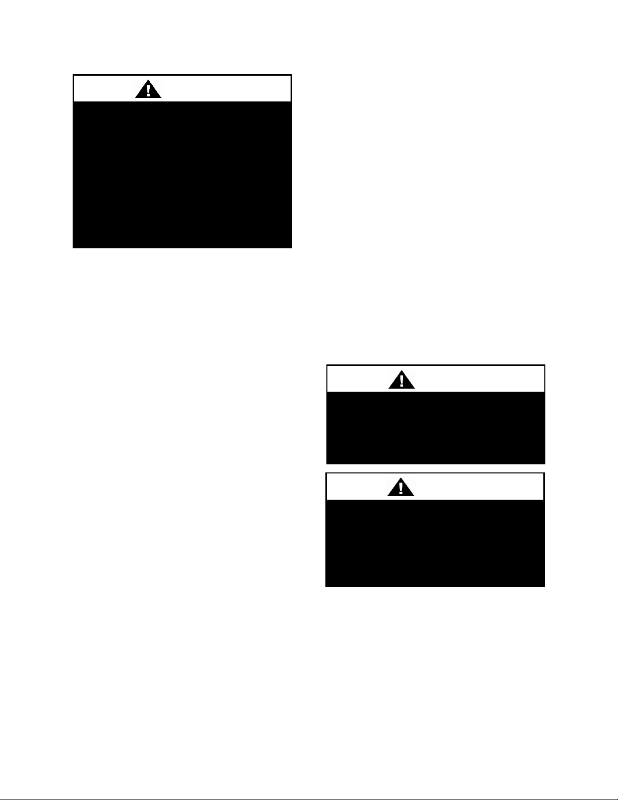
Note: Upon receipt check shipment for
items that ship loose such as filters and
remote sensors. Consult order and shipment
documentation to identify potential looseshipped items. Loose-shipped items may
have been placed inside unit cabinet for
security. Installers and owners should secure
all doors with locks or nuts and bolts to
prevent unauthorized access.
Figure 1 - Lockable Handle
Storage
This equipment is not suitable for outdoor
use of storage. If installation will not occur
immediately following delivery, store
equipment in a dry protected area away from
construction traffic and in the proper
orientation as marked on the packaging with
all internal packaging in place. Secure all
loose-shipped items.
Direct Expansion (DX) Systems
All DX systems include evaporator coils and
thermal expansion valves (TXV).
Never turn off the main power supply to the
unit, except for servicing, emergency, or
complete shutdown of the unit. When power
is cut off from the unit crankcase heaters
cannot prevent refrigerant migration into the
condensing unit compressors. This means
the compressor may cool down and liquid
refrigerant may accumulate in the
compressor. The compressor is designed to
pump refrigerant gas and damage may occur
when power is restored.
17
Page 18
Unit should not be operated without a
p-trap. Failure to install a p-trap may
result in overflow of condensate
water.
CAUTION
CRANKCASE HEATER
OPERATION
Some units are equipped with
compressor crankcase heaters,
which should be energized at least
24 hours prior to cooling operation, to
clear any liquid refrigerant from the
compressors.
CAUTION
Emergency drain pan is
recommended for all applications
where a risk of water damage to
surrounding structure or furnishings.
Refer to local codes.
CAUTION
If power to the unit must be off for more
than an hour, turn the thermostat system
switch to "OFF", or turn the unit off at the
control panel, and leave the unit off until the
main power switch has been turned on again
for at least 24 hours for units with
compressor crankcase heaters. This will give
the crankcase heater time to clear any liquid
accumulation out of the compressor before it
is started.
Always control the unit from the thermostat,
or control panel, never at the main power
supply, except for emergency or complete
shutdown of the unit.
During the cooling season, if the air flow is
reduced due to dirty air filters or any other
reason, the cooling coils can get too cold
which will cause excessive liquid to return
to the compressor. As the liquid
concentration builds up, oil is washed out of
the compressor, leaving it starved for
lubrication.
The compressor life will be seriously
shortened by reduced lubrication and the
pumping of excessive amounts of liquid oil
and refrigerant.
Note: Low Ambient Operation
Air-cooled DX units without a low ambient
option, such as condenser fan cycling or the
18
0°F low ambient option, will not operate in
the cooling mode of operation properly
when the outdoor temperature is below
55°F. Low ambient and/or economizer
options are recommended if cooling
operation below 55°F is expected.
Wiring Diagrams
Unit specific wiring diagrams are laminated
and affixed inside the controls compartment
door.
Condensate Drain Pans
Units require field installed drain p-traps and
lines to be connected to the condensate drain
pans of the unit. The lines should be the
same pipe size or larger than the drain
connection, include a p-trap, and pitch
downward toward drain. An air break should
be used with long runs of condensate lines.
Installation
AAON equipment has been designed for
quick and easy installation. Startup and
service must be performed by Factory
Trained Service Technician.
Page 19
Unit Size
Access Side
Clearance
(dimension X on
Figure 2 and
Figure 3)
All Other
Sides
V3-A
36 inches*
6 inches**
V3-B
V3-C
V3-D
V3-E
H3-A
H3-B
H3-C
H3-D
45 inches*
H3-E
60 inches*
X
(See Table 1)
X
(See Table 1)
Front
Back
Left
Right
Back
Front
Left
Right
Locating the Unit
Placement of the unit relative to ductwork,
electrical and plumbing must be carefully
considered. Return air plenum or duct can be
mounted directly to the return air flanges.
Use flexible gasket material to seal the duct
to the unit.
Verify floor, foundation or suspension
support can support the total unit weight,
including accessory weights. Unit must be
level in both horizontal axes to support the
unit and reduce noise and vibration from the
unit.
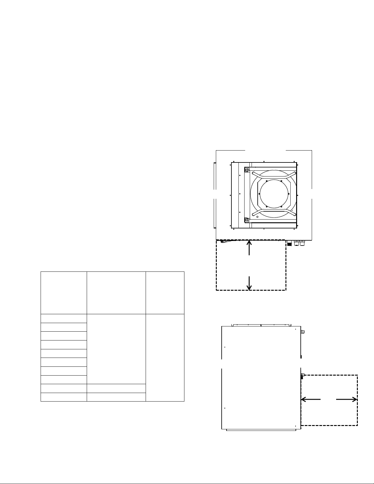
Allow adequate space for piping access and
panel removal. To ensure proper access
for field service, maintain minimum
clearances for field piping and other
obstructions as indicated by Table 1 and
Figure 2 and Figure 3. Consult local
building codes for additional service
clearance requirements. Condensate drain
connections are located on the access side of
the unit.
Table 1 - H3 and V3 Series Clearances
Floor Mounted Units
Make sure the unit is level and mounted on a
field supplied platform with a minimum
height to allow for proper depth of the
condensate line p-trap. Other installation
provisions may be necessary according to
job specifications. V3 Series vertical air
handling units are designed for upflow
applications only
Figure 2 – Minimum Clearance Required for
Access to Unit (V3 Series plan view)
Figure 3 – Minimum Clearance Required for
Access to Unit (H3 Series plan view)
*Additional clearance may be required to
allow for coil removal.
**May be installed flush depending upon
local codes.
19
Page 20
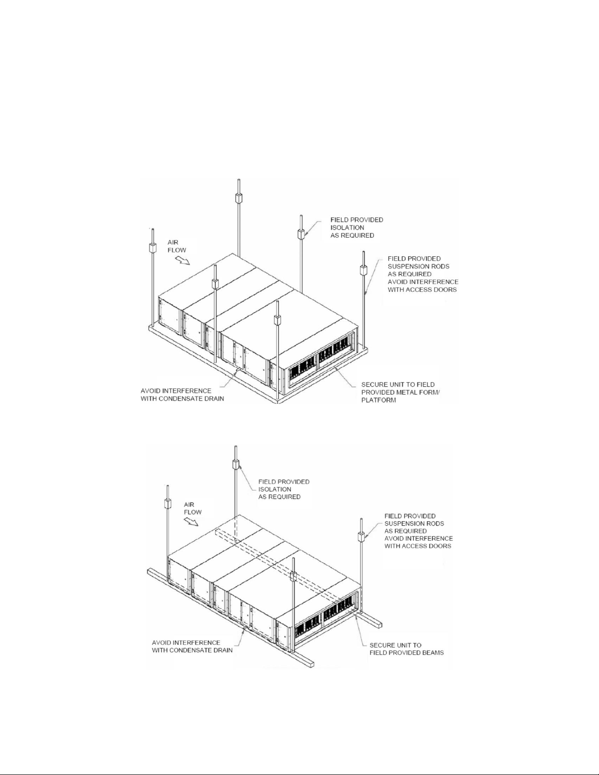
Suspended Units
H3 Series horizontal air handling units are
equipped for suspended installations. The
unit should be lifted into position by
supporting the unit with the skid used for
shipping. The air handling unit must be
installed level and care should be taken to
prevent damage to the cabinet. Other
installation provisions may be necessary
according to job specifications. Figure 4
and Figure 5 show factory recommended
methods for suspended installations. It is
the responsibility of the specifying engineer
or installing contractor to ensure the
installation is structurally safe and sound.
Figure 4 – H3 Series Platform Suspension Installation
Figure 5 – H3 Series Parallel Beam Suspension Installation
20
Page 21
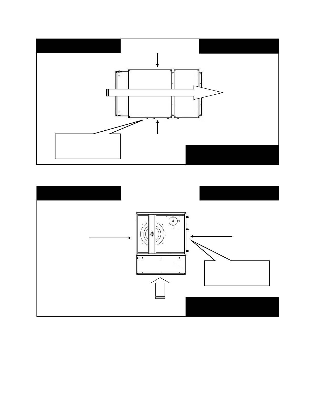
H3 Series
Return Air
“Back”
Supply Air
“Front”
Right Hand Side
Left Hand Side
Connections and service
Top View
Air Flow
Connections and service
access on right side for
right hand orientation
Right Hand Side
Left Hand Side
Return Air
“Back”
Top View
V3 Series
Air Flow
Consider the air flow to be
hitting the back of your head.
Consider the air flow to be
hitting the back of your head.
Supply Air
“Front”
access on right side for
right hand orientation
Figure 6 - H3 Series Unit Orientation
Note: Access doors may be on the “left” or “right” side as designated by the unit orientation on
the configurator string. “Back” will always be the same side as the pre-filter and return air
opening. “Front” will always be the side opposite the pre-filter and return air opening.
Figure 7 - V3 Series Unit Orientation
21
Page 22
UNIT HANDLING
Incorrect lifting can cause damage to
the unit, injury or death. Lifting
equipment capacity should exceed
unit weight by an adequate safety
factor. Always test lift unit not more
than 24 inches high to verify proper
center of gravity lift point.
WARNING
The foam insulation releases
dangerous fumes when it is burnt. Do
not cut a foam part with a cutting
torch or plasma cutter. Do not weld to
a foam filled part.
WARNING
Electric shock hazard. Before
attempting to perform any installation,
service, or maintenance, shut off all
electrical power to the unit at the
disconnect switches. Unit may have
multiple power supplies. Failure to
disconnect power could result in
dangerous operation, serious injury,
death, or property damage.
WARNING
Lifting and Handling the Unit
Before lifting unit, be sure that all shipping
material has been removed from unit.
Care should be taken if using spreader bars,
blocking or other lifting devices to prevent
damage to the cabinet, coil or fans.
Electrical
Verify the unit name plate agrees with
power supply. H3 and V3 Series units are
provided with single point power wiring
connections. Connection terminations are
made to the main terminal block. A
complete set of unit specific wiring
diagrams, showing factory and field wiring
are laminated in plastic and located inside
the control compartment door.
Route power and control wiring, separately,
through the utility entry in the unit. Do not
run power and control signal wires in the
same conduit.
22
All units require field supplied electrical
overcurrent and short circuit protection.
Device must not be sized larger than the
Maximum Overcurrent Protection (MOP)
shown on the unit nameplate.
Codes may require a disconnect switch be
within sight of the unit.
It is recommended that the field installed
overcurrent protection or disconnect switch
not be installed on the unit.
Electrical supply can enter through the
bottom or side of the controls compartment.
A single point connection to a terminal
block is provided. High voltage conductors
should enter the control panel in a separate
opening and separate conduit than low
voltage conductors.
To pass wires through the wall or roof of the
unit, a hole should be cut and conduit passed
through it. Use the following procedure to
cut a round hole in a foam panel.
Cutting Electrical Openings
1. Locate the placement of the hole. Be sure
that the conduit will not interfere with the
operation of any component or prevent
access of any door or removable panel.
Field cut openings must be a minimum of 6
Page 23

Installing Contractor is responsible
for proper sealing of the electrical
and gas entries into the unit. Failure
to seal the entries may result in
damage to the unit and property.
Three phase voltage imbalance will
cause motor overheating and
premature failure.
CAUTION
CAUTION
inches away from all components and wiring
to prevent damage due to drilling or cutting.
2. Drill a pilot hole all the way through the
foam panel.
3. Using a hole saw cut the hole through the
metal on both sides of the foam part.
4. With a knife cut the foam out of the hole.
5. After the conduit is installed in the hole
caulk the entire perimeter of the hole on
both sides with an industrial grade silicone
sealant or a duct seal compound.
If a larger cut-out is needed for additional
duct connections not provided by the
factory, or for any other reason, it is very
important that the foam be completely
sealed. Insulation covers should be
fabricated from sheet metal to cover the
foam at the cut. The edges and corners that
are not covered should then be sealed using
silicone caulking or a duct seal compound.
If a reciprocating saw is used to make the
cut-out take care that the metal skins of the
foam part do not separate from the foam,
this would result in reduced structural
integrity of the part.
Size supply conductors based on the unit
Minimum Current Ampacity (MCA) rating.
Supply conductors must be rated a minimum
of 75°C.
Protect the branch circuit in accordance with
code requirements. The unit must be
electrically grounded in accordance with
local codes, or in the absence of local codes,
the current National Electric Code,
ANSI/NFPA 70 or the current Canadian
Electrical Code CSA C22.1.
Note: Units are factory wired for 208V,
230V, 460V or 575V. In some units, the
208V and 230V options may also be
provided in single or three phase
configurations. The transformer
configuration must be checked by a
qualified technician prior to startup.
Wire power leads to the unit’s terminal
block or main disconnect. All wiring beyond
this point has been completed by AAON and
cannot be modified without effecting the
unit’s agency/safety certification.
Supply voltage must be within the min/max
range shown on the unit nameplate.
Available short circuit current should not
exceed the short circuit current rating
(SCCR) shown on the unit nameplate.
Three phase voltage imbalance will cause
motor overheating and premature failure.
The maximum allowable imbalance is 2.0%.
Voltage imbalance is defined as 100 times
the maximum deviation from the average
voltage divided by the average voltage.
Example:
(221V+230V+227V)/3 = 226V, then
100*(226V-221V)/226V = 2.2%, which
exceeds the allowable imbalance.
Check voltage imbalance at the unit
disconnect switch and at the compressor
23
Page 24

Wire Size (Stranded)
- Copper Conductors
Only
Total Wire Distance
Allowable
20 AWG
200 ft
18 AWG
350 ft
16 AWG
500 ft
14 AWG
750 ft
12 AWG
1250 ft
Rotation must be checked on all
MOTORS AND COMPRESSORS of
three phase units. Supply fan motors
should all be checked by a qualified
service technician at startup and any
wiring alteration should only be made
at the unit power connection.
CAUTION
Scroll compressors are directional
and will be damaged by operation in
the wrong direction. Low pressure
switches on compressors have been
disconnected after factory testing.
Rotation should be checked by a
qualified service technician at startup
using suction and discharge pressure
gauges and any wiring alteration
should only be made at the unit
power connection.
CAUTION
terminal. Contact your local power company
for line voltage corrections.
Installing contractor must check for proper
motor rotation and check blower motor
amperage listed on the motor nameplate is
not exceeded.
Wire control signals to the unit’s low
voltage terminal block located in the
controls compartment.
If any factory installed wiring must be
replaced, use a minimum 105°C type AWM
insulated conductors.
Thermostat Control Wiring
If a thermostat is used for unit control,
thermostat should be located on an inside
wall 4-5 feet above the floor where it will
24
not be subjected to drafts, sun exposure, or
heat from electrical fixtures of appliances.
Control wiring must deliver adequate
voltage to components to assure proper
operation. Control voltage returning from
controller circuit must be a minimum of 21
VAC. To assure proper wiring use the
following chart to determine the allowable
wiring distances.
Table 2 - Control Wiring
Total Wire Distance Allowable =
(Quantity of Control Wires) x
(Control Wire Distance)
Take the total wire distance allowable and
divide by the number of wires to be
connected. This indicates the distance
allowable for that size wire. The wiring to
the unit must not exceed the total wire
distance allowable. If the voltage at the
connectors is less than 21 VAC, isolation
relays must be installed. If under external
control 21 VAC must be field verified.
All external devices must be powered via a
separate external power supply.
Example:
A total of 8 wires must be pulled 75ft to a
control the unit. What size wire should be
used?
According to the Table 2, 16 AWG allows
for 63ft (500 ft/8 wires) and 14 AWG allows
for 94ft (750 ft/8 wires). Thus, 14 AWG
should be used.
Page 25

Unit should not be operated without
p-traps. Failure to install a p-traps
may result in overflow of condensate
water.
CAUTION
Duct Connection
Attach duct to flanges provided on the unit.
The installer is responsible for sealing ducts
to the flanges to prevent water leaks.
Refer to Figure 6 and Figure 7 for duct
connection locations. Ductwork should be
sized in accordance with the ASHRAE
Handbook. Ductwork should be installed in
accordance with NFPA Standard 90A.
When attaching duct to the unit, use a
flexible/compressible material rated for duct
connections. A three inch flexible connector
for both return and supply duct connections
is recommended.
Condensate Drain Piping
Unit may be equipped with more than one
condensate drain pan connection. A p-trap
and drain line must be installed on at least
one section’s drain connection, with the ptrap not to exceed 6” from the drain
connection. The lines should be the same
pipe size or larger than the drain connection,
include a p-trap, and pitch downward toward
drain. An air break should be used with long
runs of condensate lines.
Draw-through cooling coils will have a
negative static pressure in the drain pan area.
This will cause an un-trapped drain to back
up due to air being pulled up through the
condensate drain piping.
Condensate drain trapping and piping should
conform to all applicable governing codes.
Note: The drain pan connection(s) is a 1”
MPT fitting.
Figure 8 - Drain Trap
The X dimension on the draw-through trap
should be at least equal to the absolute value
of the negative static pressure in the drain
pan plus one inch. To calculate the static
pressure at the drain pan add the pressure
drops of all components upstream of the
drain pan, including the cooling coil, and
add the return duct static pressure. Include
the dirt allowance pressure drop for the
filters to account for the worst-case scenario.
The height from top of the bottom bend of
the trap to the bottom of the leaving pipe
must be at least equal to one half of the X
dimension. This ensures that enough water
is stored in the trap to prevent losing the
drain seal during unit startup
Note: The absolute value of the fan inlet
pressure will always be greater than or equal
to the absolute value of the static pressure in
the drain pan on draw-through units, so the
fan inlet pressure is a safe value to use for
the drain pan static pressure.
25
Page 26

Draw-Through
Drain Pan Pressure
Trap Dimensions
Negative Static
X
X/2
(inches of water)
(inch)
(inch)
-0.50
1.50
0.75
-1.00
2.00
1.00
-1.50
2.50
1.25
-2.00
3.00
1.50
-2.50
3.50
1.75
-3.00
4.00
2.00
-3.50
4.50
2.25
-4.00
5.00
2.50
Table 3 - Drain Trap Dimensions
Heating Coils
One or two row hot water and steam heating
and preheating coils can be factory installed.
All valve controls for heating coil operation
are field supplied and field installed.
Water coils should not be subjected to
entering air temperatures below 38°F to
prevent coil freeze-up. If air temperature
across the coil is going to be below this
value, use a glycol solution to match the
coldest air expected.
Chilled Water Coil
Factory installed four, six or eight row
chilled water cooling coils can be factory
mounted. All valve controls for the cooling
coil operation are field supplied and field
installed.
Electric Preheat
The modulating electric preheat option is
designed to temper the incoming outside air
to the unit based on an enable control signal
and the outside air conditions.
A 24VAC enable signal must be provided to
the [PHE] terminal to enable the operation
of the electric preheat. Once the preheat
controller is enabled it will monitor the
outside air temperature to determine if any
capacity of preheat is needed. If the outside
air temperature falls below the outside air
temperature setpoint the electric preheat will
be started up and maintain the leaving air
temperature setpoint with both SCR
controlled and staged electric preheat. Both
setpoints are set with push button LCD
interface on the preheat controller. Outside
air temperature sensors and preheat
discharge supply air temperature sensors are
factory installed and wired to the preheat
controller. Electric preheat has maximum
operating outside air temperature of 60°F
and a maximum preheat discharge air
temperature of 80°F.
[COM], [PHO] & [PHC] feedback terminals
are provided to communicate if the electric
preheat is in operation. PHO is a normally
open contact, PHC is a normally closed
contact, and COM is the common. These
terminals are not required to be connected.
[PHE] is the electric preheat operation
enable. [PH+] and [PH-] are the preheat set
point reset terminals.
Refrigerant Piping
(See back of the manual for refrigerant
piping diagrams and connection sizes.)
Piping from the condensing unit to the air
handling unit is the responsibility of the
installing contractor.
The Split System Configurator or
Refrigerant Piping Calculator in
AAONEcat32 should be used to determine
acceptable refrigerant line sizes.
The pipe sizes must be selected to meet the
actual installation conditions and not simply
based on the connection sizes at the
evaporator or condensing unit.
26
Page 27

Piping shall be in accordance with
national and local codes. Pressure
limiting devices, backflow preventers
and all other safety requirements are
the sole responsibility of the installing
contractor.
WARNING
Improper installation, adjustment,
alteration, service or maintenance
can cause property damage,
personal injury or loss of life. Startup
and service must be performed by a
Factory Trained Service Technician.
A copy of this IOM should be kept
with the unit.
WARNING
This section is for information only
and is not intended to provide all
details required by the designer or
installer of the refrigerant piping
between the condenser or
condensing unit and the air handling
unit. AAON is not responsible for
interconnecting refrigerant piping.
Consult ASHRAE Handbook –
Refrigeration and ASME Standards.
CAUTION
Only clean ACR tubing should be used.
Piping should conform to generally accepted
practices and codes.
The air handling unit coils are pressurized.
The copper caps must be punctured to
permit a gradual escape of the pressure prior
to un-sweating those caps. Immediately
couple the tubing to the indoor unit to avoid
exposing the coils to moisture. A properly
sized filter drier is furnished in the
condenser. When making solder
connections, make sure dry nitrogen flows
through the lines, when heating the copper,
to prevent oxidization inside of the copper.
When piping is completed
interconnecting piping and air handling
unit must be evacuated to 500 microns or
less and leak checked. Condenser shutoff
valves can then be opened to allow
refrigerant to flow to the air handling unit.
Thermal expansion valve bulbs should be
mounted with good thermal contact on a
horizontal section of the suction line close to
the evaporator, but outside the cabinet, and
well insulated.
Figure 9 - TXV Bulb Position
Refrigerant lines should be fastened and
supported according to local codes.
Unit should be charged based on
determination of sub-cooling and superheat.
See Adjusting Refrigerant Charge section
for more information.
Refrigerant reheat coil for the modulating
hot gas reheat option is factory installed.
Liquid line receiver should be installed at
the condensing unit. Care must be taken not
to cross circuits in reheat systems.
27
Page 28

Line sizes must be selected to meet
actual installation conditions, not
simply based on the connection sizes
at the condensing unit or air handling
unit.
CAUTION
Modulating Hot Gas Reheat Piping:
1. Run a hot gas reheat line from the
condensing unit and connect it to the inlet of
the stub-out on the reheat coil. The inlet
connection is the top (or highest) stub-out of
the reheat coil. Connect the hot gas line
from the outdoor unit to the upper stub-out
connection of the reheat coil.
2. Run a liquid line from the discharge of the
reheat coil through a tee connection. Run a
liquid line from the condenser, through a
check valve to the other side of the tee. Run
a liquid line from the tee to the liquid line
stub-out of the evaporator coil.
3. Run a suction line from the evaporator
coil outlet stub-out to the condensing unit.
Determining Refrigerant Line Size
The piping between the condenser and low
side must ensure:
1. Minimum pressure drop, and
2. Continuous oil return, and
3. Prevention of liquid refrigerant slugging,
or carryover
Minimizing the refrigerant line size is
favorable from an economic perspective,
reducing installation costs, and reducing the
potential for leakage. However, as pipe
diameters narrow, pressure-reducing
frictional forces increase.
Excessive suction line pressure drop causes
loss of compressor capacity and increased
power usage resulting in reduced system
28
efficiency. Excessive pressure drops in the
liquid line can cause the liquid refrigerant to
flash, resulting in faulty TXV operation and
improper system performance. In order to
operate efficiently and cost effectively,
while avoiding malfunction, refrigeration
systems must be designed to minimize both
cost and pressure loss.
Equivalent Line Length
All line lengths discussed in this manual,
unless specifically stated otherwise, are
Equivalent Line Lengths. The frictional
pressure drop through valves, fittings, and
accessories is determined by establishing the
equivalent length of straight pipe of the
same diameter. Always use equivalent line
lengths when calculating pressure drop.
Special piping provisions must be taken
when lines are run underground, up vertical
risers, or in excessively long line runs.
Liquid Line Sizing
When sizing the liquid line, it is important to
minimize the refrigerant charge to reduce
installation costs and improve system
reliability. This can be achieved by
minimizing the liquid line diameter.
However, reducing the pipe diameter will
increase the velocity of the liquid refrigerant
which increases the frictional pressure drop
in the liquid line, and causes other
undesirable effects such as noise.
Maintaining the pressure in the liquid line is
critical to ensuring sufficient saturation
temperature, avoiding flashing upstream of
the TXV, and maintaining system
efficiency. Pressure losses through the
liquid line due to frictional contact, installed
accessories, and vertical risers are
inevitable. Maintaining adequate subcooling at the condenser to overcome these
losses is the only method to ensure that
liquid refrigerant reaches the TXV.
Page 29

Liquid refrigerant traveling upwards in a
riser loses head pressure. If the evaporator is
below the condenser, and the liquid line
does not include risers, the gravitational
force will increase the pressure of the liquid
refrigerant. This will allow the refrigerant to
withstand greater frictional losses without
the occurrence of flashing prior to the TXV.
A moisture-indicating sight glass may be
field installed in the liquid line to indicate
the occurrence of premature flashing or
moisture in the line. The sight glass should
not be used to determine if the system is
properly charged. Use temperature and
pressure measurements to determine
liquid sub-cooling, not the sight glass.
Liquid Line Routing
Care should be taken with vertical risers.
When the system is shut down, gravity will
pull liquid down the vertical column, and
back to the condenser when it is below the
evaporator. This could potentially result in
compressor flooding. A check valve can be
installed in the liquid line where the liquid
column rises above the condenser to prevent
this. The liquid line is typically pitched
along with the suction line, or hot gas line,
to minimize the complexity of the
configuration.
Liquid Line Insulation
When the liquid line is routed through
regions where temperature losses are
expected, no insulation is required, as this
may provide additional sub-cooling to the
refrigerant. When routing the liquid line
through high temperature areas, insulation of
the line is appropriate to avoid loss of subcooling through heat gain.
Liquid Line Guidelines
In order to ensure liquid at the TXV,
frictional losses must not exceed available
sub-cooling. A commonly used guideline to
consider is a system design with pressure
losses due to friction through the line not to
exceed a corresponding 1-2°F change in
saturation temperature.
If the velocity of refrigerant in the liquid line
is too great, it could cause excessive noise or
piping erosion. The recommended
maximum velocities for liquid lines are 100
fpm from the condenser to a receiver tank to
discourage fluid backup, and 300 fpm from
receiver tank to the evaporator to minimize
valve induced liquid hammer.
Liquid Line Accessories
Liquid line shut off valves and filter driers
are factory provided. Filter driers must be
field installed on 2-5 ton units. The total
length equivalent of pressure losses through
valves, elbows and fittings must be
considered when adding additional
components in the field. It is a good practice
to utilize the fewest elbows that will allow
the mating units to be successfully joined.
Suction Line Sizing
The suction line is more critical than the
liquid line from a design and construction
standpoint. More care must be taken to
ensure that adequate velocity is achieved to
return oil to the compressor at minimum
loading conditions. However, reducing the
piping diameter to increase the velocity at
minimal load can result in excessive
pressure losses, capacity reduction, and
noise at full load. The suction line also
dictates the position of the TXV sensing
bulb for proper operation of the TXV.
Suction Line Routing
Pitch the suction line in the direction of flow
(about 1 foot per 100 feet of length) to
maintain oil flow towards the compressor,
and keep it from flooding back into the
evaporator. Crankcase heaters are provided
to keep any condensed refrigerant that
29
Page 30

Circuits with variable capacity scroll
compressors require suction riser
traps every 10 feet.
CAUTION
collects in the compressor from causing
damage or wear. Make sure to provide
support to maintain suction line positioning,
and insulate completely between the
evaporator and condensing unit.
It is important to consider part load
operation when sizing suction lines. At
minimum capacity, refrigerant velocity may
not be adequate to return oil up the vertical
riser. Decreasing the diameter of the vertical
riser will increase the velocity, but also the
frictional loss.
A double suction riser can be applied to the
situation of part load operation with a
suction riser. A double suction riser is
designed to return oil at minimum load
while not incurring excessive frictional
losses at full load. A double suction riser
consists of a small diameter riser in parallel
with a larger diameter riser, and a trap at the
base of the large riser. At minimum
capacity, refrigerant velocity is not sufficient
to carry oil up both risers, and it collects in
the trap, effectively closing off the larger
diameter riser, and diverting refrigerant up
the small riser where velocity of the
refrigerant is sufficient to maintain oil flow.
At full load, the mass flow clears the trap of
oil, and refrigerant is carried through both
risers. The smaller diameter pipe should be
sized to return oil at minimum load, while
the larger diameter pipe should be sized so
that flow through both pipes provides
acceptable pressure drop at full load.
Suction Line Insulation
The entire suction line should be insulated.
This prevents condensation from forming on
the line, and reduces any potential loss in
capacity associated with heat gain.
Suction Line Guidelines
For proper performance, suction line
velocities less than a 4,000 fpm maximum
are recommended. The minimum velocity
required to return oil is dependent on the
pipe diameter, however, a general guideline
of 1,000 fpm minimum may be applied.
In a fashion similar to the liquid line, a
common guideline to consider is a system
design with pressure losses due to friction
through the line not to exceed a
corresponding 1-2°F change in saturation
temperature.
At points where small pipe size can be used
to provide sufficient velocity to return oil in
vertical risers at part loads, greater pressure
losses are incurred at full loads. This can be
compensated for by over sizing the
horizontal runs and vertical drop sections.
This will however require additional
refrigerant charge.
Circuits with variable capacity scroll
compressors require suction riser traps every
10 feet.
Suction Line Accessories
If the job requirements specify suction
accumulators, they must be separately
purchased and field installed.
Hot Gas Bypass Line
Hot Gas Bypass is available for use with DX
systems that may experience low suction
pressure during the operating cycle. This
may be due to varying load conditions
associated with VAV applications or units
supplying a large percentage of outside air.
The system is designed to divert refrigerant
30
Page 31

from the compressor discharge to the low
pressure side of the system in order to keep
the evaporator from freezing and to maintain
adequate refrigerant velocity for oil return at
minimum load.
Hot discharge gas is redirected to the
evaporator inlet via an auxiliary side
connector (ASC) to false load the evaporator
when reduced suction pressure is sensed.
Field piping between the condensing unit
and the evaporator is required.
Hot Gas Bypass Piping Considerations for
Evaporator above Condensing Unit
Pitch the hot gas bypass (HGB) line
downward in the direction of refrigerant
flow, toward the evaporator.
When installing hot gas bypass risers, a
drain leg must be provided at the lowest
point in the system. The drain leg must be
vertical, its diameter should be the same as
the diameter of the riser, and it should be 1
foot long. Install a sight glass in the drain
leg for observation. Run an oil drip line,
using 1/8 inch capillary tube, 10 feet in
length, from the drain leg to the suction line.
Connect the oil drip line below the sight
glass and 1 inch above the bottom of the
drain leg. HGB valves are adjustable.
Factory HGB valve settings will be
sufficient for most applications, but may
require slight adjustments for some
applications, including some make up air
applications.
Insulate the entire length of the HGB line
with a minimum 1 inch thick Armaflex
insulation.
Hot Gas Bypass Piping Considerations for
Evaporator below Condensing Unit
The line must slope downward from the
HGB valve toward the evaporator.
Hot Gas Bypass Line Guidelines
Choose a small size line to ensure oil return,
and minimize refrigerant charge.
Maintain velocities below a maximum of
4,000 fpm. A general minimum velocity
guideline to use is approximately 1,000 fpm.
Hot Gas Reheat
The AAON modulating hot gas reheat
system diverts hot discharge gas from the
condenser to the air handling unit through
the hot gas line. Field piping between the
condensing unit and the air handler is
required.
The line delivers the hot discharge gas to the
reheat coil and/or the hot gas bypass valve,
so it is sized as a discharge line.
Discharge lines should be sized to ensure
adequate velocity of refrigerant to ensure oil
return, avoid excessive noise associated with
velocities that are too high, and to minimize
efficiency losses associated with friction.
Pitch the hot gas line in the direction of flow
for oil return.
When installing hot gas reheat risers, a drip
leg must be provided at the lowest point in
the system. The drip leg must be vertical, its
diameter should be the same as the diameter
of the riser, and it should be 1 foot long. Run
a drip line, using 1/8 inch capillary tube, 10
feet in length, from the drip leg to the
suction line. Connect the drip line a
minimum of 1-inch above the bottom of the
drain leg.
Insulate the entire length of the hot gas line
with a minimum 1 inch thick Armaflex
insulation.
31
Page 32

Improper installation, adjustment,
alteration, service or maintenance
can cause property damage,
personal injury or loss of life. Startup
and service must be performed by a
Factory Trained Service Technician.
A copy of this IOM should be kept
with the unit.
WARNING
Electric shock hazard. Shut off all
electrical power to the unit to avoid
shock hazard or injury from rotating
parts.
WARNING
Hot Gas Reheat Guidelines
Maintain velocities below a maximum of
3,500 fpm. A general minimum velocity
guideline is 2,000 fpm.
Startup
(See back of the manual for startup form)
During startup, it is necessary to perform
routine checks on the performance of the
unit. This includes checking of the air flow,
the air filters and refrigerant charge.
Supply Fans
H3 and V3 Series units are equipped with
direct drive backward curved plenum supply
fan assemblies or belt driven backward
curved plenum supply fans that deliver the
air volume specified according to unit size
and job requirements.
Fan Air Flow Adjustment
A specific air volume is delivered by the
fans with air volume bands in the blower
wheels, Electronically Commutated Motors
(ECM), or Variable Frequency Drives
32
(VFD). Field air flow adjustment may be
required at startup.
Air volume bands for the wheels are sized
according to the unit’s air delivery
specifications and can also be ordered from
the factory for field installation.
Air Flow Adjustment
If reduced air volume is required an air
volume band or larger air volume band can
be installed within the blower wheel to
reduce the amount of air delivered by the
wheel.
If the unit is factory equipped with the air
volume band and additional air volume is
required, the band can be removed from the
wheel.
Use fan program in AAONEcat32 to
determine the new band size for the required
cfm and static pressure.
The following photos of a wheel are
provided for practical guidelines only in
order to identify the air band location in the
wheel. Actual field installation of the air
band into the wheel will require access into
and through the blower wheel venture,
which may require removal of the blower
motor and wheel.
Air volume bands are made of aluminum,
sized and equipped with easy bend tabs that
are to be inserted into pre-punched slots
provided on the wheel. Once the band has
been inserted into the slots, it MUST BE
secured by bending the tabs over from the
back side of the wheel and also MUST BE
secured from the inside by connecting the
ends together with a pop-rivet in the holes
provided on the ends of the band.
Page 33

If the band is field installed, a hand held
pop-rivet tool is recommended for
connecting the band ends together. Caution
must be taken to assure that the band is
tightly installed and no damage, denting or
alteration to the wheel or blades occurs
during the installation.
Figure 10 - Supply Fan Banding
33
Page 34

Before completing startup and
leaving the unit a complete operating
cycle should be observed to verify
that all components are functioning
properly.
CAUTION
The Clean Air Act of 1990 bans the
intentional venting of refrigerant
(CFC’s and HCFC’s) as of July 1,
1992. Approved methods of recovery,
recycling or reclaiming must be
followed. Fines and/or incarceration
may be levied for non-compliance.
CAUTION
Filters
Do not operate the unit without filters in
place. Unit should be checked for correct
filter placement during startup. Operation of
the equipment without filters will result in a
clogged evaporator coil.
Adjusting Refrigerant Charge
Adjusting the charge of a system in the field
must be based on determination of liquid
sub-cooling and evaporator superheat. On a
system with a TXV liquid sub-cooling is
more representative of the charge than
evaporator superheat but both measurements
must be taken.
Before Charging
Unit being charged must be at or near full
load conditions before adjusting the charge.
Units equipped with hot gas reheat must be
charged with the hot gas reheat valves
closed while the unit is in cooling mode to
get the proper charge. After charging, unit
should be operated in reheat
34
(dehumidification) mode to check for
correct operation.
After adding or removing charge the system
must be allowed to stabilize, typically 10-15
minutes, before making any other
adjustments.
The type of unit and options determine the
ranges for liquid sub-cooling and evaporator
superheat. Refer to the tables below when
determining the proper sub-cooling.
Checking Liquid Sub-Cooling
Measure the temperature of the liquid line as
it leaves the condenser.
Read the gauge pressure at the liquid line
close to the point where the temperature was
taken. Use liquid line pressure as it will vary
from discharge pressure due to condenser
pressure drop.
Convert the pressure obtained to a saturated
temperature using the appropriate refrigerant
temperature-pressure chart.
Subtract the measured liquid line
temperature from the saturated temperature
to determine the liquid sub-cooling.
Compare calculated sub-cooling to the table
below for the appropriate unit type and
options.
Checking Evaporator Superheat
Measure the temperature of the suction line
close to the compressor.
Read gauge pressure at the suction line close
to the compressor.
Convert the pressure obtained to a saturated
temperature using the appropriate refrigerant
temperature-pressure chart.
Page 35

Air-Cooled Condenser / Air-Source Heat
Pump
Sub-Cooling
12-18°F
Sub-Cooling with
Hot Gas Reheat
15-22°F
Superheat
8-15°F
Water-Cooled Condenser / Water Source
Heat Pump
Sub-Cooling
6-10°F
Sub-Cooling with
Hot Gas Reheat
8-12°F
Superheat
8-15°F
Thermal expansion valve must be
adjust to approximately 8-15°F of
suction superheat. Failure to have
sufficient superheat will damage the
compressor and void the warranty.
CAUTION
DO NOT OVERCHARGE!
Refrigerant overcharging leads to
excess refrigerant in the condenser
coils resulting in elevated compressor
discharge pressure.
CAUTION
DO NOT OVERCHARGE!
Refrigerant overcharging leads to
excess refrigerant in the condenser
coils resulting in elevated compressor
discharge pressure.
CAUTION
Subtract the saturated temperature from the
measured suction line temperature to
determine the evaporator superheat.
Compare calculated superheat to the table
below for the appropriate unit type and
options.
Table 4 - Acceptable Air-Cooled
Refrigeration Circuit Values
Table 5 - Acceptable Water-Cooled
Refrigeration Circuit Values
Adjusting Sub-Cooling and Superheat
Temperatures
The system is overcharged if the sub-cooling
temperature is too high and the evaporator is
fully loaded (low loads on the evaporator
result in increased sub-cooling) and the
evaporator superheat is within the
temperature range as shown in the table
above (high superheat results in increased
sub-cooling).
Correct an overcharged system by reducing
the amount of refrigerant in the system to
lower the sub-cooling.
The system is undercharged if the superheat
is too high and the sub-cooling is too low
Correct an undercharged system by adding
refrigerant to the system to reduce superheat
and raise sub-cooling.
If the sub-cooling is correct and the
superheat is too high, the TXV may need
adjustment to correct the superheat. Before
adjusting the TXV, verify the sensing bulb is
in the correct position according to Figure 9
and follows the guidelines below.
1. The suction line is clean where the
sensing bulb is attached.
2. The entire length of the sensing bulb is in
contact with the suction line.
3. The sensing bulb should be placed several
inches downstream of the equalizer line.
35
Page 36

°F
PSIG
°F
PSIG
°F
PSIG
°F
PSIG
°F
PSIG
20
78.3
47
134.7
74
213.7
101
321.0
128
463.2
21
80.0
48
137.2
75
217.1
102
325.6
129
469.3
22
81.8
49
139.7
76
220.6
103
330.2
130
475.4
23
83.6
50
142.2
77
224.1
104
334.9
131
481.6
24
85.4
51
144.8
78
227.7
105
339.6
132
487.8
25
87.2
52
147.4
79
231.3
106
344.4
133
494.1
26
89.1
53
150.1
80
234.9
107
349.3
134
500.5
27
91.0
54
152.8
81
238.6
108
354.2
135
506.9
28
92.9
55
155.5
82
242.3
109
359.1
136
513.4
29
94.9
56
158.2
83
246.0
110
364.1
137
520.0
30
96.8
57
161.0
84
249.8
111
369.1
138
526.6
31
98.8
58
163.8
85
253.7
112
374.2
139
533.3
32
100.9
59
166.7
86
257.5
113
379.4
140
540.1
33
102.9
60
169.6
87
261.4
114
384.6
141
547.0
34
105.0
61
172.5
88
265.4
115
389.9
142
553.9
35
107.1
62
175.4
89
269.4
116
395.2
143
560.9
36
109.2
63
178.4
90
273.5
117
400.5
144
567.9
37
111.4
64
181.5
91
277.6
118
405.9
145
575.1
38
113.6
65
184.5
92
281.7
119
411.4
146
582.3
39
115.8
66
187.6
93
285.9
120
416.9
147
589.6
40
118.1
67
190.7
94
290.1
121
422.5
148
596.9
41
120.3
68
193.9
95
294.4
122
428.2
149
604.4
42
122.7
69
197.1
96
298.7
123
433.9
150
611.9
43
125.0
70
200.4
97
303.0
124
439.6
44
127.4
71
203.6
98
307.5
125
445.4
45
129.8
72
207.0
99
311.9
126
451.3
46
132.2
73
210.3
100
316.4
127
457.3
4. The sensing bulb is fully insulated.
5. If the sensing bulb is installed on a
vertical portion of the suction line, the
sensing bulb should be placed upstream of
suction line trap.
Table 6 - R-410A Refrigerant Temperature-Pressure Chart
36
Page 37

Improper installation, adjustment,
alteration, service or maintenance
can cause property damage,
personal injury or loss of life.
Installation and service must be
performed by a qualified installer. A
copy of this IOM should be kept with
the unit.
WARNING
Operation
Unit operations should be controlled with
thermostat or unit controller, never at the
main power supply, except for emergency or
complete shutdown of the unit.
Electric Heating Operation
When a call for heating (G and W1, W2,
etc.) is made the supply fan motors and
electric resistance heaters will energize.
Heating is accomplished by passing
electrical current through a specified amount
of resistance heaters which will produce the
required heat.
On a fault condition the main limit located
in the supply air or the auxiliary limit
located downstream the supply blower will
remove power from all contactors.
Steam or Hot Water Preheating Operation
Valve control for steam and hot water
heating coils are by others. Heating is
accomplished by passing steam or hot water
through the steam or hot water coil
assembly.
Chilled Water or Non-Compressorized DX Cooling Operation
Valve controls for chilled water cooling coil
and non-compressorized DX coil are by
others.
Modulating Electric Preheat
Electric preheat is used to temper the
incoming outside air to the unit based on an
enable control signal and outside air
conditions. Electric preheat has a maximum
operation outside air temperature of 60°F
and a maximum preheat discharge air
temperature of 80°F.
Maintenance
(See back of the manual for maintenance
log.)
At least once each year, a qualified service
technician should check out the unit. Supply
fans, evaporator coils and air filters should
be inspected monthly.
Periodically during operation, it is necessary
to perform routine service checks on the
performance of the unit. This includes
checking of the air flow, the air filters,
condenser water flow and refrigerant charge.
See Startup section for information on air
flow adjustment and refrigerant charge
adjustment.
DX Cooling
Set unit controls to cooling mode of
operation with supply fans on. Check the
fans for correct operating direction,
amperage and voltage. Check compressor
operation, rotation, amperage and voltage to
the unit nameplate (check the amperage on
the load side of the compressor contactor).
Condensate Drain Pans
Drain pans will have moisture present and
require periodic cleaning to prevent
microbial growth. Cleaning of the drain pans
will also prevent any possible plugging of
the drain lines and overflow of the pan itself.
Cleaning of the drain pans and inside of the
unit should be done only by qualified
personnel.
37
Page 38

Electric shock hazard. Shut off all
electrical power to the unit to avoid
shock hazard or injury from rotating
parts.
WARNING
Harsh chemicals, household bleach,
or acid cleaners should not be used
to clean outdoor or indoor e-coated
coils. These cleaners can be very
difficult to rinse out of the coil and
can accelerate corrosion and attack
the e-coating. If there is dirt below the
surface of the coil, use the
recommended coil cleaners.
High velocity water from a pressure
washer or compressed air should
only be used at a very low pressure
to prevent fin and/or coil damages.
The force of the water or air jet may
bend the fin edges and increase
airside pressure drop. Reduced unit
performance or nuisance unit
shutdowns may occur.
CAUTION
CAUTION
E-Coated Coil Cleaning
Documented routine cleaning of e-coated
coils is required to maintain coating
warranty coverage.
Surface loaded fibers or dirt should be
removed prior to water rinse to prevent
restriction of airflow. If unable to back wash
the side of the coil opposite of the coils
entering air side, then surface loaded fibers
or dirt should be removed with a vacuum
cleaner. If a vacuum cleaner is not available,
a soft non-metallic bristle brush may be
used. In either case, the tool should be
applied in the direction of the fins. Coil
surfaces can be easily damaged (fin edges
bent over) if the tool is applied across the
fins.
Use of a water stream, such as a garden
hose, against a surface loaded coil will drive
the fibers and dirt into the coil. This will
make cleaning efforts more difficult. Surface
loaded fibers must be completely removed
prior to using low velocity clean water rinse.
A monthly clean water rinse is
recommended for coils that are applied in
coastal or industrial environments to help to
remove chlorides, dirt, and debris. It is very
important when rinsing, that water
temperature is less than 130°F and pressure
is than 900 psig to avoid damaging the fin
edges. An elevated water temperature (not to
exceed 130°F) will reduce surface tension,
increasing the ability to remove chlorides
and dirt.
38
Quarterly cleaning is essential to extend
the life of an e-coated coil and is required
to maintain coating warranty coverage.
Coil cleaning shall be part of the unit’s
regularly scheduled maintenance
procedures. Failure to clean an e-coated coil
will void the warranty and may result in
reduced efficiency and durability.
For routine quarterly cleaning, first clean the
coil with the below approved coil
cleaner. After cleaning the coils with the
approved cleaning agent, use the approved
chloride remover to remove soluble salts and
revitalize the unit.
Recommended Coil Cleaner
The following cleaning agent, assuming it is
used in accordance with the manufacturer’s
directions on the container for proper mixing
and cleaning, has been approved for use on
e-coated coils to remove mold, mildew,
Page 39

Blower wheels and bands must be
inspected for excessive dust build up
periodically and cleaned if required.
Excessive dust build up on blower
wheels may cause an unbalanced
state; leading to vibration and/or
component failure. Damages due to
excessive dust build up will not be
covered under factory warranty.
CAUTION
Electric shock hazard. Shut off all
electrical power to the unit to avoid
shock hazard or injury from rotating
parts.
WARNING
dust, soot, greasy residue, lint and other
particulate:
Enviro-Coil Concentrate, Part Number HEC01.
Recommended Chloride Remover
CHLOR*RID DTS™ should be used to
remove soluble salts from the e-coated coil,
but the directions must be followed closely.
This product is not intended for use as a
degreaser. Any grease or oil film should first
be removed with the approved cleaning
agent.
Remove Barrier - Soluble salts adhere
themselves to the substrate. For the effective
use of this product, the product must be able
to come in contact with the salts. These salts
may be beneath any soils, grease or dirt;
therefore, these barriers must be removed
prior to application of this product. As in all
surface preparation, the best work yields the
best results.
Apply CHLOR*RID DTS - Apply directly
onto the substrate. Sufficient product must
be applied uniformly across the substrate to
thoroughly wet out surface, with no areas
missed. This may be accomplished by use of
a pump-up sprayer or conventional spray
gun. The method does not matter, as long as
the entire area to be cleaned is wetted. After
the substrate has been thoroughly wetted,
the salts will be soluble and is now only
necessary to rinse them off.
Rinse - It is highly recommended that a hose
be used, as a pressure washer will damage
the fins. The water to be used for the rinse is
recommended to be of potable quality,
though a lesser quality of water may be used
if a small amount of CHLOR*RID DTS is
added. Check with CHLOR*RID
International, Inc. for recommendations on
lesser quality rinse water.
Supply Fans
Supply Fan Lubrication
All original blower motors and bearings are
furnished with factory lubrication. Some
applications will require that bearings be relubricated periodically. The schedule will
depend on the operating duty, temperature
variations or other severe atmospheric
conditions.
Bearings should be re-lubricated when at
normal operating temperatures, but not
running. Rotate the fan shaft by hand and
add only enough grease to purge the seals.
DO NOT OVERLUBRICATE.
Recommended greases are:
SHELL OIL - DOLIUM R
CHEVRON OIL - SRI No. 2
TEXACO INC. - PREMIUM RB
Filter Replacement
Monthly filter inspection is required to
maintain optimum unit efficiency.
39
Page 40

Electric shock hazard. Shut off all
electrical power to the unit to avoid
shock hazard or injury from rotating
parts.
WARNING
It is strongly recommended that filter media
be replaced monthly. Filters are located
upstream of the evaporator coil. Open access
panel and pull filters straight out to inspect
all of the filters. Replace filters with the size
indicated on each filter. Arrow on the
replacement filters must point towards the
blower.
40
Replacement Parts
Parts for AAON equipment may be obtained
from AAON at www.aaonparts.com. When
ordering parts, reference the unit serial
number and part number.
AAON-Longview Customer Service Department
203 Gum Springs Road
Longview, TX 75602
Ph: 903-236-4403
Fax: 903-236-4463
www.aaon.com
Note: Before calling, technician should have
model and serial number of the unit
available for the service department to help
answer questions regarding the unit.
Page 41

Feature 6A
(Quantity) Size
Type
0
No Pre Filters
A
(1) 16” x 25” x 2”
Pleated, 30% Eff, MERV 8
B
(1) 16” x 25” x 4”
Pleated, 30% Eff, MERV 8
C
Pleated, 65% Eff, MERV 11
D
Pleated, 85% Eff, MERV 13
E
Pleated, 95% Eff, MERV 14
F
(1) 16” x 25” x 2” and
(1) 16” x 25” x 4”
Pleated, 30% Eff, MERV 8 and
Pleated, 30% Eff, MERV 8
G
Pleated, 30% Eff, MERV 8 and
Pleated, 65% Eff, MERV 11
H
Pleated, 30% Eff, MERV 8 and
Pleated, 85% Eff, MERV 13
J
Pleated, 30% Eff, MERV 8 and
Pleated, 95% Eff, MERV 14
Filter Information
Table 7 - H3 Series A Cabinet Pre Filters
Table 8 - V3 Series A Cabinet Pre Filters
41
Page 42

Feature 6A
(Quantity) Size
Type
0
No Pre Filters
A
(2) 16” x 20” x 2”
Pleated, 30% Eff, MERV 8
B
(2) 16” x 20” x 4”
Pleated, 30% Eff, MERV 8
C
Pleated, 65% Eff, MERV 11
D
Pleated, 85% Eff, MERV 13
E
Pleated, 95% Eff, MERV 14
F
(2) 16” x 20” x 2” and
(2) 16” x 20” x 4”
Pleated, 30% Eff, MERV 8 and
Pleated, 30% Eff, MERV 8
G
Pleated, 30% Eff, MERV 8 and
Pleated, 65% Eff, MERV 11
H
Pleated, 30% Eff, MERV 8 and
Pleated, 85% Eff, MERV 13
J
Pleated, 30% Eff, MERV 8 and
Pleated, 95% Eff, MERV 14
Feature 6A
(Quantity) Size
Type
0
No Pre Filters
A
(1) 24” x 24” x 2”
Pleated, 30% Eff, MERV 8
B
(1) 24” x 24” x 4”
Pleated, 30% Eff, MERV 8
C
Pleated, 65% Eff, MERV 11
D
Pleated, 85% Eff, MERV 13
E
Pleated, 95% Eff, MERV 14
F
(1) 24” x 24” x 2” and
(1) 24” x 24” x 4”
Pleated, 30% Eff, MERV 8 and
Pleated, 30% Eff, MERV 8
G
Pleated, 30% Eff, MERV 8 and
Pleated, 65% Eff, MERV 11
H
Pleated, 30% Eff, MERV 8 and
Pleated, 85% Eff, MERV 13
J
Pleated, 30% Eff, MERV 8 and
Pleated, 95% Eff, MERV 14
Table 9 - H3 Series B Cabinet Pre Filters
Table 10 - V3 Series B Cabinet Pre Filters
42
Page 43

Feature 6A
(Quantity) Size
Type
0
No Pre Filters
A
(2) 20” x 20” x 2" and
(1) 16” x 20” x 2"
Pleated, 30% Eff, MERV 8
B
(2) 20” x 20” x 4" and
(1) 16” x 20” x 4"
Pleated, 30% Eff, MERV 8
C
Pleated, 65% Eff, MERV 11
D
Pleated, 85% Eff, MERV 13
E
Pleated, 95% Eff, MERV 14
F
(2) 20” x 20” x 2" and
(1) 16” x 20” x 2"
and
(2) 20” x 20” x 4" and
(1) 16” x 20” x 4"
Pleated, 30% Eff, MERV 8 and
Pleated, 30% Eff, MERV 8
G
Pleated, 30% Eff, MERV 8 and
Pleated, 65% Eff, MERV 11
H
Pleated, 30% Eff, MERV 8 and
Pleated, 85% Eff, MERV 13
J
Pleated, 30% Eff, MERV 8 and
Pleated, 95% Eff, MERV 14
Feature 6A
(Quantity) Size
Type
0
No Pre Filters
A
(4) 16” x 20” x 2”
Pleated, 30% Eff, MERV 8
B
(4) 16” x 20” x 4”
Pleated, 30% Eff, MERV 8
C
Pleated, 65% Eff, MERV 11
D
Pleated, 85% Eff, MERV 13
E
Pleated, 95% Eff, MERV 14
F
(4) 16” x 20” x 2” and
(4) 16” x 20” x 4”
Pleated, 30% Eff, MERV 8 and
Pleated, 30% Eff, MERV 8
G
Pleated, 30% Eff, MERV 8 and
Pleated, 65% Eff, MERV 11
H
Pleated, 30% Eff, MERV 8 and
Pleated, 85% Eff, MERV 13
J
Pleated, 30% Eff, MERV 8 and
Pleated, 95% Eff, MERV 14
Table 11 - H3 Series C Cabinet Pre Filters
Table 12 - V3 Series C Cabinet Pre Filters
43
Page 44

Feature 6A
(Quantity) Size
Type
0
No Pre Filters
A
(1) 20” x 20” x 2” and
(4) 16” x 20” x 2"
Pleated, 30% Eff, MERV 8
B
(1) 20” x 20” x 4” and
(4) 16” x 20” x 4"
Pleated, 30% Eff, MERV 8
C
Pleated, 65% Eff, MERV 11
D
Pleated, 85% Eff, MERV 13
E
Pleated, 95% Eff, MERV 14
F
(1) 20” x 20” x 2” and
(4) 16” x 20” x 2"
and
(1) 20” x 20” x 4” and
(4) 16” x 20” x 4"
Pleated, 30% Eff, MERV 8 and
Pleated, 30% Eff, MERV 8
G
Pleated, 30% Eff, MERV 8 and
Pleated, 65% Eff, MERV 11
H
Pleated, 30% Eff, MERV 8 and
Pleated, 85% Eff, MERV 13
J
Pleated, 30% Eff, MERV 8 and
Pleated, 95% Eff, MERV 14
Feature 6A
(Quantity) Size
Type
0
No Pre Filters
A
(2) 20” x 20” x 2” and
(4) 16” x 20” x 2"
Pleated, 30% Eff, MERV 8
B
(2) 20” x 20” x 4” and
(4) 16” x 20” x 4"
Pleated, 30% Eff, MERV 8
C
Pleated, 65% Eff, MERV 11
D
Pleated, 85% Eff, MERV 13
E
Pleated, 95% Eff, MERV 14
F
(2) 20” x 20” x 2” and
(4) 16” x 20” x 2"
and
(2) 20” x 20” x 4” and
(4) 16” x 20” x 4"
Pleated, 30% Eff, MERV 8 and
Pleated, 30% Eff, MERV 8
G
Pleated, 30% Eff, MERV 8 and
Pleated, 65% Eff, MERV 11
H
Pleated, 30% Eff, MERV 8 and
Pleated, 85% Eff, MERV 13
J
Pleated, 30% Eff, MERV 8 and
Pleated, 95% Eff, MERV 14
Table 13 - H3 Series D Cabinet Pre Filters
Table 14 - V3 Series D Cabinet Pre Filters
44
Page 45

Feature 6A
(Quantity) Size
Type
0
No Pre Filters
A
(10) 16” x 20” x 2”
Pleated, 30% Eff, MERV 8
B
(10) 16” x 20” x 4”
Pleated, 30% Eff, MERV 8
C
Pleated, 65% Eff, MERV 11
D
Pleated, 85% Eff, MERV 13
E
Pleated, 95% Eff, MERV 14
F
(10) 16” x 20” x 2” and
(10) 16” x 20” x 4”
Pleated, 30% Eff, MERV 8 and
Pleated, 30% Eff, MERV 8
G
Pleated, 30% Eff, MERV 8 and
Pleated, 65% Eff, MERV 11
H
Pleated, 30% Eff, MERV 8 and
Pleated, 85% Eff, MERV 13
J
Pleated, 30% Eff, MERV 8 and
Pleated, 95% Eff, MERV 14
Feature 6A
(Quantity) Size
Type
0
No Pre Filters
A
(3) 20” x 20” x 2” and
(6) 16” x 20” x 2"
Pleated, 30% Eff, MERV 8
B
(3) 20” x 20” x 4” and
(6) 16” x 20” x 4"
Pleated, 30% Eff, MERV 8
C
Pleated, 65% Eff, MERV 11
D
Pleated, 85% Eff, MERV 13
E
Pleated, 95% Eff, MERV 14
F
(3) 20” x 20” x 2” and
(6) 16” x 20” x 2"
and
(3) 20” x 20” x 4” and
(6) 16” x 20” x 4"
Pleated, 30% Eff, MERV 8 and
Pleated, 30% Eff, MERV 8
G
Pleated, 30% Eff, MERV 8 and
Pleated, 65% Eff, MERV 11
H
Pleated, 30% Eff, MERV 8 and
Pleated, 85% Eff, MERV 13
J
Pleated, 30% Eff, MERV 8 and
Pleated, 95% Eff, MERV 14
Table 15 - H3 Series E Cabinet Pre Filters
Table 16 - V3 Series E Cabinet Pre Filters
45
Page 46

Feature 6B
(Quantity) Size
Type
0
No Unit Filters
A
(1) 16” x 25” x 2”
Pleated, 30% Eff, MERV 8
B
(1) 16” x 25” x 4”
Pleated, 30% Eff, MERV 8
C
Pleated, 65% Eff, MERV 11
D
Pleated, 85% Eff, MERV 13
E
Pleated, 95% Eff, MERV 14
F
(1) 16” x 25” x 2” and
(1) 16” x 25” x 4”
Pleated, 30% Eff, MERV 8 and
Pleated, 30% Eff, MERV 8
G
Pleated, 30% Eff, MERV 8 and
Pleated, 65% Eff, MERV 11
H
Pleated, 30% Eff, MERV 8 and
Pleated, 85% Eff, MERV 13
J
Pleated, 30% Eff, MERV 8 and
Pleated, 95% Eff, MERV 14
Table 17 - H3 Series A Cabinet Unit Filters
Table 18 - V3 Series A Cabinet Unit Filters
46
Page 47

Feature 6B
(Quantity) Size
Type
0
No Unit Filters
A
(2) 16” x 20” x 2”
Pleated, 30% Eff, MERV 8
B
(2) 16” x 20” x 4”
Pleated, 30% Eff, MERV 8
C
Pleated, 65% Eff, MERV 11
D
Pleated, 85% Eff, MERV 13
E
Pleated, 95% Eff, MERV 14
F
(2) 16” x 20” x 2” and
(2) 16” x 20” x 4”
Pleated, 30% Eff, MERV 8 and
Pleated, 30% Eff, MERV 8
G
Pleated, 30% Eff, MERV 8 and
Pleated, 65% Eff, MERV 11
H
Pleated, 30% Eff, MERV 8 and
Pleated, 85% Eff, MERV 13
J
Pleated, 30% Eff, MERV 8 and
Pleated, 95% Eff, MERV 14
Feature 6B
(Quantity) Size
Type
0
No Unit Filters
A
(1) 24” x 24” x 2”
Pleated, 30% Eff, MERV 8
B
(1) 24” x 24” x 4”
Pleated, 30% Eff, MERV 8
C
Pleated, 65% Eff, MERV 11
D
Pleated, 85% Eff, MERV 13
E
Pleated, 95% Eff, MERV 14
F
(1) 24” x 24” x 2” and
(1) 24” x 24” x 4”
Pleated, 30% Eff, MERV 8 and
Pleated, 30% Eff, MERV 8
G
Pleated, 30% Eff, MERV 8 and
Pleated, 65% Eff, MERV 11
H
Pleated, 30% Eff, MERV 8 and
Pleated, 85% Eff, MERV 13
J
Pleated, 30% Eff, MERV 8 and
Pleated, 95% Eff, MERV 14
Table 19 - H3 Series B Cabinet Unit Filters
Table 20 - V3 Series B Cabinet Unit Filters
47
Page 48

Feature 6B
(Quantity) Size
Type
0
No Unit Filters
A
(4) 16” x 20” x 2”
Pleated, 30% Eff, MERV 8
B
(4) 16” x 20” x 4”
Pleated, 30% Eff, MERV 8
C
Pleated, 65% Eff, MERV 11
D
Pleated, 85% Eff, MERV 13
E
Pleated, 95% Eff, MERV 14
F
(4) 16” x 20” x 2” and
(4) 16” x 20” x 4”
Pleated, 30% Eff, MERV 8 and
Pleated, 30% Eff, MERV 8
G
Pleated, 30% Eff, MERV 8 and
Pleated, 65% Eff, MERV 11
H
Pleated, 30% Eff, MERV 8 and
Pleated, 85% Eff, MERV 13
J
Pleated, 30% Eff, MERV 8 and
Pleated, 95% Eff, MERV 14
Feature 6B
(Quantity) Size
Type
0
No Unit Filters
A
(4) 18” x 24” x 2"
Pleated, 30% Eff, MERV 8
B
(4) 18” x 24” x 4"
Pleated, 30% Eff, MERV 8
C
Pleated, 65% Eff, MERV 11
D
Pleated, 85% Eff, MERV 13
E
Pleated, 95% Eff, MERV 14
F
(4) 18” x 24” x 2"
and
(4) 18” x 24” x 4"
Pleated, 30% Eff, MERV 8 and
Pleated, 30% Eff, MERV 8
G
Pleated, 30% Eff, MERV 8 and
Pleated, 65% Eff, MERV 11
H
Pleated, 30% Eff, MERV 8 and
Pleated, 85% Eff, MERV 13
J
Pleated, 30% Eff, MERV 8 and
Pleated, 95% Eff, MERV 14
Table 21 - V3 Series C Cabinet Unit Filters
Table 22 - V3 Series D Cabinet Unit Filters
48
Page 49

Feature 6C
(Quantity) Size
Type
0
No Final Filters
A
(1) 16” x 25” x 2”
Pleated, 30% Eff, MERV 8
B
(1) 16” x 25” x 12”
Cartridge, 65% Eff, MERV 11
C
Cartridge, 85% Eff, MERV 13
D
Cartridge, 95% Eff, MERV 14
E
(1) 16” x 25” x 2” and
(1) 16” x 25” x 12”
Pleated, 30% Eff, MERV 8 and
Cartridge, 65% Eff, MERV 11
F
Pleated, 30% Eff, MERV 8 and
Cartridge, 85% Eff, MERV 13
G
Pleated, 30% Eff, MERV 8 and
Cartridge, 95% Eff, MERV 14
Feature 6C
(Quantity) Size
Type
0
No Final Filters
A
(1) 16” x 25” x 2”
Pleated, 30% Eff, MERV 8
Feature 6C
(Quantity) Size
Type
0
No Final Filters
A
(2) 16” x 20” x 2”
Pleated, 30% Eff, MERV 8
B
(2) 16” x 20” x 12”
Cartridge, 65% Eff, MERV 11
C
Cartridge, 85% Eff, MERV 13
D
Cartridge, 95% Eff, MERV 14
E
(2) 16” x 20” x 2” and
(2) 16” x 20” x 12”
Pleated, 30% Eff, MERV 8 and
Cartridge, 65% Eff, MERV 11
F
Pleated, 30% Eff, MERV 8 and
Cartridge, 85% Eff, MERV 13
G
Pleated, 30% Eff, MERV 8 and
Cartridge, 95% Eff, MERV 14
Feature 6C
(Quantity) Size
Type
0
No Final Filters
A
(2) 24” x 12” x 2”
Pleated, 30% Eff, MERV 8
Table 23 - H3 Series A Cabinet Final Filters
Table 24 - V3 Series A Cabinet Final Filters
Table 25 - H3 Series B Cabinet Final Filters
Table 26 - V3 Series B Cabinet Final Filters
49
Page 50

Feature 6C
(Quantity) Size
Type
0
No Final Filters
A
(2) 20” x 20” x 2” and
(1) 16” x 20” x 2"
Pleated, 30% Eff, MERV 8
B
(2) 20” x 20” x12” and
(1) 16” x 20” x 12"
Cartridge, 65% Eff, MERV 11
C
Cartridge, 85% Eff, MERV 13
D
Cartridge, 95% Eff, MERV 14
E
(2) 20” x 20” x 2” and
(1) 16” x 20” x 2"
and
(2) 20” x 20” x12” and
(1) 16” x 20” x 12"
Pleated, 30% Eff, MERV 8 and
Cartridge, 65% Eff, MERV 11
F
Pleated, 30% Eff, MERV 8 and
Cartridge, 85% Eff, MERV 13
G
Pleated, 30% Eff, MERV 8 and
Cartridge, 95% Eff, MERV 14
Feature 6C
(Quantity) Size
Type
0
No Final Filters
A
(4) 16” x 20” x 2”
Pleated, 30% Eff, MERV 8
Feature 6C
(Quantity) Size
Type
0
No Final Filters
A
(1) 20” x 20” x 2" and
(4) 16” x 20” x 2"
Pleated, 30% Eff, MERV 8
B
(1) 20” x 20” x 12" and
(4) 16” x 20” x 12"
Cartridge, 65% Eff, MERV 11
C
Cartridge, 85% Eff, MERV 13
D
Cartridge, 95% Eff, MERV 14
E
(1) 20” x 20” x 2" and
(4) 16” x 20” x 2"
and
(1) 20” x 20” x 12" and
(4) 16” x 20” x 12"
Pleated, 30% Eff, MERV 8 and
Cartridge, 65% Eff, MERV 11
F
Pleated, 30% Eff, MERV 8 and
Cartridge, 85% Eff, MERV 13
G
Pleated, 30% Eff, MERV 8 and
Cartridge, 95% Eff, MERV 14
Feature 6C
(Quantity) Size
Type
0
No Final Filters
A
(2) 20” x 20” x 2" and
(4) 16” x 20” x 2"
Pleated, 30% Eff, MERV 8
Table 27 - H3 Series C Cabinet Final Filters
Table 28 - V3 Series C Cabinet Final Filters
Table 29 - H3 Series D Cabinet Final Filters
50
Table 30 - V3 Series D Cabinet Final Filters
Page 51

Feature 6C
(Quantity) Size
Type
0
No Final Filters
A
(10) 16” x 20” x 2”
Pleated, 30% Eff, MERV 8
B
(10) 16” x 20” x 12”
Cartridge, 65% Eff, MERV 11
C
Cartridge, 85% Eff, MERV 13
D
Cartridge, 95% Eff, MERV 14
E
(10) 16” x 20” x 2” and
(10) 16” x 20” x 12”
Pleated, 30% Eff, MERV 8 and
Cartridge, 65% Eff, MERV 11
F
Pleated, 30% Eff, MERV 8 and
Cartridge, 85% Eff, MERV 13
G
Pleated, 30% Eff, MERV 8 and
Cartridge, 95% Eff, MERV 14
Feature 6C
(Quantity) Size
Type
0
No Final Filters
A
(3) 20 x 20 x 2” and
(6) 16 x 20 x 2"
Pleated, 30% Eff, MERV 8
Table 31 - H3 Series E Cabinet Final Filters
Table 32 - V3 Series E Cabinet Final Filters
51
Page 52

Refrigerant Piping Diagrams
52
Figure 11 – A/C only piping, AHU above CU
Page 53

Figure 12 – A/C only piping, AHU below CU
53
Page 54

54
Figure 13 – Modulating hot gas reheat piping, AHU above CU
Page 55

Figure 14 – Modulating hot gas reheat piping, AHU below CU
55
Page 56

56
Figure 15 – Hot gas bypass piping, AHU above CU
Page 57

Figure 16 – Hot gas bypass piping, AHU below CU
57
Page 58

58
Figure 17 – Modulating hot gas reheat with hot gas bypass piping, AHU above CU
Page 59

Figure 18 – Modulating hot gas reheat with hot gas bypass piping, AHU below CU
59
Page 60

60
Figure 19 – Heat pump piping, AHU above CU
Page 61

Figure 20 – Heat pump piping, AHU below CU
61
Page 62

62
Figure 21 – Heat pump with modulating hot gas reheat piping, AHU above CU
Figure 22 – Heat pump with modulating hot gas reheat piping, AHU below CU
Page 63

63
Page 64

Job Name:_______________________________________________
Date:______________
Address:______________________________________________________________________
______________________________________________________________________________
Model Number:_________________________________________________________________
Serial Number:_____________________________________________
Tag:_______________
Startup Contractor:______________________________________________________________
Address:______________________________________________________________________
_______________________________________________________
Phone:______________
Installing contractor should verify the following items.
1. Is there any visible shipping damage?
Yes No
2. Is the unit level?
Yes No
3. Are the unit clearances adequate for service and operation?
Yes No
4. Do all access doors open freely and are the handles operational?
Yes No
5. Have all shipping braces been removed?
Yes No
6. Have all electrical connections been tested for tightness?
Yes No
7. Does the electrical service correspond to the unit nameplate?
Yes No
8. On 208/230V units, has transformer tap been checked?
Yes No
9. Has overcurrent protection been installed to match the unit nameplate
requirement?
Yes No
10. Have all set screws on the fans been tightened?
Yes No
11. Do all fans rotate freely?
Yes No
12. Does the field water piping to the unit appear to be correct per design
parameters?
Yes No
13. Is all copper tubing isolated so that it does not rub?
Yes No
14. Have the damper assemblies been inspected?
Yes No
15. Are air filters installed with proper orientation?
Yes No
16. Have condensate drain and p-trap been connected?
Yes No
17. Is the TXV sensing bulb in the correct location?
Yes No
18. Does the TXV sensing bulb have proper thermal contact and is properly
insulated?
Yes No
Pre Startup Checklist
H3/V3 Series Startup Form
64
Page 65

Ambient Dry Bulb Temperature ________°F
Ambient Wet Bulb Temperature ________°F
Alignment
Check Rotation
Nameplate Amps________
Number
hp
L1
L2
L3
1
2
Band Size_____________________
VAV Controls_________________
VFD Frequency________________
Check Rotation
Number
L1
L2
L3
Head
Pressure
PSIG
Suction
Pressure
PSIG
Crankcase
Heater
Amps 1 2 3
4
Pressure
Saturated
Temperature
Line
Temperature
Sub-cooling
Superheat
Discharge
N/A
N/A
Suction
N/A
Liquid
N/A
Pressure
Saturated
Temperature
Line
Temperature
Sub-cooling
Superheat
Discharge
N/A
N/A
Suction
N/A
Liquid
N/A
Pressure
Saturated
Temperature
Line
Temperature
Sub-cooling
Superheat
Discharge
N/A
N/A
Suction
N/A
Liquid
N/A
Ambient Temperature
Supply Fan Assembly
Compressors/DX Cooling
Refrigeration System 1 - Cooling Mode
Refrigeration System 2 - Cooling Mode
Refrigeration System 3 - Cooling Mode
65
Page 66

Pressure
Saturated
Temperature
Line
Temperature
Sub-cooling
Superheat
Discharge
N/A
N/A
Suction
N/A
Liquid
N/A
Pressure
Saturated
Temperature
Line
Temperature
Sub-cooling
Superheat
Discharge
N/A
N/A
Suction
N/A
Liquid
N/A
Pressure
Saturated
Temperature
Line
Temperature
Sub-cooling
Superheat
Discharge
N/A
N/A
Suction
N/A
Liquid
N/A
Pressure
Saturated
Temperature
Line
Temperature
Sub-cooling
Superheat
Discharge
N/A
N/A
Suction
N/A
Liquid
N/A
Pressure
Saturated
Temperature
Line
Temperature
Sub-cooling
Superheat
Discharge
N/A
N/A
Suction
N/A
Liquid
N/A
Refrigeration System 4 - Cooling Mode
Refrigeration System 1 - Heating Mode (Heat Pump Only)
Refrigeration System 2 - Heating Mode (Heat Pump Only)
Refrigeration System 3 - Heating Mode (Heat Pump Only)
Refrigeration System 4 - Heating Mode (Heat Pump Only)
66
Page 67

Water-Cooled Condenser
Air-Cooled Condenser
No Water Leaks
Condenser Safety Check
Water Flow ________ gpm
Water Inlet Temperature ________°F
Water Outlet Temperature ________°F
Operation Check
Damper Wiring Check
Gears Check
Damper Actuator Type:__________________________________________________________
Economizer Changeover Type and Operations:_______________________________________
1. Has the entire system been flushed and pressure checked?
Yes No
2. Has the entire system been filled with fluid?
Yes No
3. Has air been bled from the heat exchangers and piping?
Yes No
4. Is the glycol the proper type and concentration (N/A if water)?
Yes No
5. Is there a minimum load of 50% of the design load?
Yes No
6. Has the water piping been insulated?
Yes No
7. What is the freeze point of the glycol (N/A if water)? ______________________________
Unit Configuration
Mixing Box Dampers
Water/Glycol System
67
Page 68

Alignment
Check Rotation
Nameplate Amps________
Number
hp
L1
L2
L3
1
2
3
4
5
6
Stages__________
Limit Lockout
Aux. Limit Lockout
Stage
Amps
Stage
Amps 1 5 2 6 3 7
4 8
Limit Lockout
Aux. Limit Lockout
Outside Air Temperature Setpoint__________°F
Preheat Leaving Air Temperature Setpoint__________°F
Stage
Amps
Stage
Amps 1 3 2 4
Air-Cooled Condenser Fans
Electric Heating
Electric Preheating
68
Page 69

Entry Date
Action Taken
Name/Tel.
Maintenance Log
This log must be kept with the unit. It is the responsibility of the owner and/or
maintenance/service contractor to document any service, repair or adjustments. AAON Service
and Warranty Departments are available to advise and provide phone help for proper operation
and replacement parts. The responsibility for proper startup, maintenance and servicing of the
equipment falls to the owner and qualified licensed technician.
Page 70

Literature Change History
June 2010
Revision of the IOM adding PVC and CPVC piping Caution.
June 2011
Update of the IOM adding the electronic startup form.
April 2012
Update of the IOM changing the 2” pleated 30% efficient filter from MERV 7 to MERV 8,
adding additional modulating hot gas reheat options to Feature 2, changing the Service
Clearances to allow for coil removal, adding condensate drain connection size information,
changing the required suction riser trap requirement for variable capacity scroll compressor
circuits to every 10 feet, correcting the length of the drip line in piping diagrams to 120”,
correcting the Modulating Hot Gas Reheat and Modulating Hot Gas Reheat with Hot Gas Bypass
piping diagrams to show the liquid line tee connection factory installed, adding the Heat Pump
with Field Installed Modulating Hot Gas Reheat Split System Piping Diagram, adding the index
of tables and figures, and updating the table of contents.
July 2012
Update of the IOM showing that the steam heating coil option is stream distributing (Model
Option B1 = 4)
June 2013
Updated for Rev B design revision change, updated configurator options, updated the filter
information, updated the minimum clearance definitions, added suspension installation
recommendations, and updated the piping diagrams. New part number assigned.
November 2013
Added proper sealing of electrical and gas entries caution.
May 2014
Added electric preheat options and installation information and added TXV sensing bulb
installation instructions.
Page 71

Page 72

AAON
203 Gum Springs Rd.
Longview, TX 75602-1721
Phone: 903-236-4403
Fax: 903-236-4463
www.aaon.com
H3/V3 Series
Installation, Operation &
Maintenance
R94201 · Rev. A · 140521
(ACP J00188)
It is the intent of AAON to provide accurate and current product information. However, in the
interest of product improvement, AAON reserves the right to change pricing, specifications,
and/or design of its product without notice, obligation, or liability.
Copyright © AAON, all rights reserved throughout the world.
AAON® and AAONAIRE® are registered trademarks of AAON, Inc., Tulsa, OK.
 Loading...