

Page 1
RQ SERIES
Packaged Rooftop Units, Heat Pumps,
& Outdoor Air Handling Units
Installation, Operation,
Do not touch any electrical switch; do not
Immediately call your gas supplier from a
phone remote from the building. Follow the
If you cannot reach your gas supplier, call
Startup and service must be performed by a
WARNING
service instructions in this manual.
WARNING
& Maintenance
FIRE OR EXPLOSION HAZARD
Failure to follow safety warnings
exactly could result in serious
injury, death or property damage.
Be sure to read and understand
the installation, operation and
Improper installation, adjustment,
alteration, service or maintenance
can cause serious injury, death or
property damage.
A copy of this IOM should be kept
with the unit.
o Do not store gasoline or other flammable
vapors and liquids in the vicinity of this or any
other appliance
o WHAT TO DO IF YOU SMELL GAS
Do not try to light any appliance.
use any phone in your building.
Leave the building immediately.
gas supplier’s instructions.
the fire department.
o
Factory Trained Service Technician.
Page 2

Page 3

Table of Contents
Safety .............................................................................................................................................. 9
RQ Series Feature String Nomenclature ....................................................................................... 14
General Information ...................................................................................................................... 23
Codes and Ordinances............................................................................................................... 23
Receiving Unit .......................................................................................................................... 24
Packaged Direct Expansion (DX) Units ................................................................................... 25
Gas or Electric Heating ............................................................................................................. 26
Wiring Diagrams ....................................................................................................................... 27
Condensate Drain Pan ............................................................................................................... 27
Installation..................................................................................................................................... 28
Unit Location ............................................................................................................................ 28
Setting the Curb ........................................................................................................................ 28
Forklifting the Unit ................................................................................................................... 31
Lifting the Unit ......................................................................................................................... 32
Vertical Duct Connection ......................................................................................................... 34
Seismic Curb Installation .......................................................................................................... 35
Horizontal Duct Connection ..................................................................................................... 37
Outside Air Rain Hood ............................................................................................................. 37
Metal Mesh Filters .................................................................................................................... 38
Electrical ................................................................................................................................... 39
Thermostat Control Wiring ................................................................................................... 41
Gas Heating ............................................................................................................................... 41
Maximum Piping Capacities ................................................................................................. 42
Piping Sizing Examples ........................................................................................................ 42
Inlet and Manifold Pressures ................................................................................................ 43
Gas Pressure Regulator & Overpressure Protection Device ................................................. 43
Additional Gas Piping Considerations .................................................................................. 44
Leak Testing.......................................................................................................................... 45
Refrigerant-to-Water Heat Exchanger ...................................................................................... 45
Open Loop Applications ....................................................................................................... 45
Freezing Water in the Heat Exchanger ................................................................................. 46
Water Piping ......................................................................................................................... 47
Condensate Drain Piping .......................................................................................................... 49
3
Page 4

Discharge and Suction Line Piping ........................................................................................... 49
Heating Coils ............................................................................................................................ 52
Chilled Water Coil .................................................................................................................... 52
Startup ........................................................................................................................................... 53
Filters ........................................................................................................................................ 53
Adjusting Refrigerant Charge ................................................................................................... 53
Checking Liquid Sub-Cooling .............................................................................................. 54
Checking Evaporator Superheat ........................................................................................... 54
Adjusting Sub-Cooling and Superheat Temperatures ........................................................... 54
Gas Heater Instructions ............................................................................................................. 57
Supply Fan EC Motor Startup................................................................................................... 58
Condenser Fan EC Motor Startup ............................................................................................. 59
Operation....................................................................................................................................... 60
Thermostat Operation ............................................................................................................... 60
Packaged DX Cooling Operation and Control .......................................................................... 60
Gas Heater Operation ................................................................................................................ 60
Electric Heating Operation ....................................................................................................... 61
Steam or Hot Water Preheating and Heating Operation ........................................................... 61
Chilled Water or Non-Compressorized DX Cooling Operation ............................................... 61
Maintenance .................................................................................................................................. 62
Gas Heating ............................................................................................................................... 62
Gas Heat Exchanger Removal .................................................................................................. 63
DX Cooling ............................................................................................................................... 63
Condenser Fan .......................................................................................................................... 64
Condensate Drain Pans ............................................................................................................. 64
Evaporator Coil ......................................................................................................................... 64
E-Coated Coil Cleaning ............................................................................................................ 65
Microchannel Coil Cleaning ..................................................................................................... 67
Supply Fan ................................................................................................................................ 67
Phase and Brownout Protection ................................................................................................ 68
Variable Capacity Compressor Controller ................................................................................ 70
Filter Replacement .................................................................................................................... 71
Replacement Parts ..................................................................................................................... 72
Appendix A - Heat Exchanger Corrosion Resistance ................................................................... 73
4
Page 5

Appendix B - Thermistor Temperature vs. Resistance Values ..................................................... 75
RQ Series Startup Form ................................................................................................................ 76
Maintenance Log .......................................................................................................................... 80
Literature Change History............................................................................................................. 81
R94490 · Rev. D · 130530
5
Page 6

Index of Tables and Figures
Tables:
Table 1 - Electric and Gas Heating Capacities ............................................................................. 26
Table 2 - Auxiliary Electric Heating Capacities ........................................................................... 27
Table 3 - Unit Clearances ............................................................................................................. 28
Table 4 - Control Wiring ............................................................................................................... 41
Table 5 - 2-6 ton Gas Connections ............................................................................................... 41
Table 6 - Natural Gas (ft3/hr) ........................................................................................................ 42
Table 7 - Propane (kBtu/hr) .......................................................................................................... 42
Table 8 - Gas Piping Supports ...................................................................................................... 43
Table 9 - Glycol Freezing Points .................................................................................................. 47
Table 10 - Condenser Water Connections .................................................................................... 47
Table 11 - Hot Water Coil Connection Sizes ................................................................................ 52
Table 12 - Steam Coil Connection Sizes ...................................................................................... 52
Table 13 - Chilled Water Coil Connection Sizes .......................................................................... 52
Table 14 - Acceptable Refrigeration Circuit Values ..................................................................... 54
Table 15 - R-410A Refrigerant Temperature-Pressure Chart ....................................................... 56
Table 16 - EC Condenser Fan Cycling Options ............................................................................ 59
Table 17 - Demand Signal vs. Compressor Capacity Modulation ................................................ 70
Table 17 - RQ Series 2-6 ton Pre Filters ....................................................................................... 71
Table 18 - RQ Series 2-6 ton Unit Filters ..................................................................................... 72
Table 19 - RQ Series 2-6 ton Energy Recovery Wheel Filters ..................................................... 72
6
Page 7

Figures:
Figure 1 - Lockable Handle .......................................................................................................... 24
Figure 2 - RQ Series Orientation .................................................................................................. 28
Figure 3 - RQ Cabinet Standard and Power Exhaust Gasket Locations ....................................... 30
Figure 4 - Forklifting an RQ Series Unit from the Side ............................................................... 31
Figure 5 - Forklifting an RQ Series Unit from the Front .............................................................. 31
Figure 6 - Lifting Details of a 2-6 ton Standard or Power Exhaust Unit ...................................... 32
Figure 7 - Lifting Details of a 2-6 ton Energy Recovery Wheel Unit .......................................... 33
Figure 8 - Vertical Duct Connection ............................................................................................. 34
Figure 9 - Solid Bottom Seismic Curb with Filters ...................................................................... 35
Figure 10 - Seismic Solid Bottom Curb without Filters Cross Section ........................................ 36
Figure 11 - Seismic Solid Bottom Curb without Filters Detail A................................................. 36
Figure 12 - Seismic Solid Bottom Curb without Filters Detail B ................................................. 36
Figure 13 - Seismic Rigid Mount Curb Cross Section ................................................................. 37
Figure 14 - Horizontal duct connections ....................................................................................... 37
Figure 15 - RQ Series unit Closed Rain Hood .............................................................................. 38
Figure 16 - RQ Series unit Open Rain Hood ................................................................................ 38
Figure 17 - Rain Hood with Metal Mesh Filter Rack Installation ................................................ 38
Figure 18 - Unit Base Utility Entry............................................................................................... 39
Figure 19 - Back View of Power Switch from Control Compartment ......................................... 39
Figure 20 - RQ Series Gas Heat Exchanger .................................................................................. 42
Figure 21 - Example 2-6 ton through the Base Gas Piping .......................................................... 44
Figure 22 - Post Corner Hole Location ......................................................................................... 50
Figure 23 - Post Back Hole Location ............................................................................................ 50
Figure 24 - Post Corner Hole Piping............................................................................................. 51
Figure 25 - Post Back Hole Location ............................................................................................ 51
Figure 26 - Gas Heater Instructions .............................................................................................. 57
Figure 27 - PIN Connectors on EC Supply Fan Motor Electronics .............................................. 58
Figure 28 - Gas Heat Exchanger ................................................................................................... 63
Figure 29 - Removal of a Condenser Fan Assembly .................................................................... 64
Figure 30 - Evaporator Coil Access .............................................................................................. 65
Figure 31 - 2-6 ton Supply Fan ..................................................................................................... 68
Figure 32 - RQ Supply Fan Removal Bolts .................................................................................. 68
Figure 33 - RQ Supply Fan Removal Slide .................................................................................. 68
Figure 34 - Voltage Monitor ......................................................................................................... 68
Figure 35 - Variable Capacity Compressor Controller ................................................................. 70
Figure 36 - Compressor Controller Flash Code Details................................................................ 71
Figure 37 - RQ Series 2-6 ton Standard Filter Layout .................................................................. 72
7
Page 8

8
Page 9
Safety
ELECTRIC SHOCK, FIRE OR
EXPLOSION HAZARD
Failure to follow safety warnings
exactly could result in dangerous
operation, serious injury, death or
property damage.
Improper servicing could result in
dangerous operation, serious injury,
death or property damage.
Before servicing, disconnect all
electrical power to the furnace.
More than one disconnect may be
provided.
When servicing controls, label all
wires prior to disconnecting.
Reconnect wires correctly.
Verify proper operation after
servicing. Secure all doors with
key-lock or nut and bolt.
WARNING
Attention should be paid to the following statements:
NOTE - Notes are intended to clarify the unit installation, operation and maintenance.
CAUTION - Caution statements are given to prevent actions that may result in
equipment damage, property damage, or personal injury.
WARNING - Warning statements are given to prevent actions that could result in
equipment damage, property damage, personal injury or death.
DANGER - Danger statements are given to prevent actions that will result in equipment
damage, property damage, severe personal injury or death.
WHAT TO DO IF YOU SMELL GAS
Do not try to turn on unit.
Shut off main gas supply.
Do not touch any electric switch.
Do not use any phone in the
building.
Never test for gas leaks with an
open flame.
Use a gas detection soap solution
and check all gas connections
and shut off valves.
CAUTION
Electric shock hazard. Before
servicing, shut off all electrical power
to the unit, including remote
disconnects, to avoid shock hazard
or injury from rotating parts. Follow
proper Lockout-Tagout procedures.
WARNING
9
Page 10
FIRE, EXPLOSION OR CARBON
MONOXIDE POISONING HAZARD
Failure to replace proper controls
could result in fire, explosion or
carbon monoxide poisoning. Failure
to follow safety warnings exactly
could result in serious injury, death or
property damage. Do not store or use
gasoline or other flammable vapors
and liquids in the vicinity of this
appliance.
VARIABLE FREQUENCY DRIVES
Do not leave VFDs unattended in
hand mode or manual bypass.
Damage to personnel or equipment
can occur if left unattended. When in
hand mode or manual bypass mode
VFDs will not respond to controls or
alarms.
WARNING
WARNING
During installation, testing, servicing
and troubleshooting of the equipment
it may be necessary to work with live
electrical components. Only a
qualified licensed electrician or
individual properly trained in handling
live electrical components shall
perform these tasks.
Standard NFPA-70E, an OSHA
regulation requiring an Arc Flash
Boundary to be field established and
marked for identification of where
appropriate Personal Protective
Equipment (PPE) be worn, should be
followed.
WARNING
ROTATING COMPONENTS
Unit contains fans with moving parts
that can cause serious injury. Do not
open door containing fans until the
power to the unit has been
disconnected and fan wheel has
stopped rotating.
WARNING
GROUNDING REQUIRED
All field installed wiring must be
completed by qualified personnel.
Field installed wiring must comply
with NEC/CEC, local and state
electrical code requirements. Failure
to follow code requirements could
result in serious injury or death.
Provide proper unit ground in
accordance with these code
requirements.
WARNING
Electric motor over-current protection
and overload protection may be a
function of the Variable Frequency
Drive to which the motors are wired.
Never defeat the VFD motor overload
feature. The overload ampere setting
must not exceed 115% of the electric
motors FLA rating as shown on the
motor nameplate.
CAUTION
10
Page 11

UNIT HANDLING
To prevent injury or death lifting
equipment capacity shall exceed unit
weight by an adequate safety factor.
Always test-lift unit not more than 24
inches high to verify proper center of
gravity lift point to avoid unit damage,
injury or death.
WARNING
Failure to properly drain and vent
coils when not in use during freezing
temperature may result in coil and
equipment damage.
CAUTION
Rotation must be checked on all
MOTORS AND COMPRESSORS of
3 phase units at startup by a qualified
service technician. Scroll
compressors are directional and can
be damaged if rotated in the wrong
direction. Compressor rotation must
be checked using suction and
discharge gauges. Fan motor rotation
should be checked for proper
operation. Alterations should only be
made at the unit power connection
CAUTION
WATER PRESSURE
Prior to connection of condensing
water supply, verify water pressure is
less than maximum pressure shown
on unit nameplate. To prevent injury
or death due to instantaneous
release of high pressure water, relief
valves should be field supplied on
system water piping.
WARNING
Do not use oxygen, acetylene or air
in place of refrigerant and dry
nitrogen for leak testing. A violent
explosion may result causing injury or
death.
WARNING
Always use a pressure regulator,
valves and gauges to control
incoming pressures when pressure
testing a system. Excessive pressure
may cause line ruptures, equipment
damage or an explosion which may
result in injury or death.
WARNING
To prevent damage to the unit, do not
use acidic chemical coil cleaners. Do
not use alkaline chemical coil
cleaners with a pH value greater than
8.5, after mixing, without first using
an aluminum corrosion inhibitor in the
cleaning solution.
CAUTION
Some chemical coil cleaning
compounds are caustic or toxic. Use
these substances only in accordance
with the manufacturer’s usage
instructions. Failure to follow
instructions may result in equipment
damage, injury or death.
WARNING
11
Page 12
WATER FREEZING
Failure of the condenser due to
freezing will allow water to enter the
refrigerant circuit and will cause
extensive damage to the refrigerant
circuit components. Any damage to
the equipment as a result of water
freezing in the condenser is excluded
from coverage under AAON
warranties and the heat exchanger
manufacturer warranties.
Do not clean DX refrigerant coils with
hot water or steam. The use of hot
water or steam on refrigerant coils
will cause high pressure inside the
coil tubing and damage to the coil.
CAUTION
Door compartments containing
hazardous voltage or rotating parts
are equipped with door latches to
allow locks. Door latch are shipped
with nut and bolts requiring tooled
access. If you do not replace the
shipping hardware with a pad lock
always re-install the nut & bolt after
closing the door.
CAUTION
Cleaning the cooling tower or
condenser water loop with harsh
chemicals such as hydrochloric acid
(muriatic acid), chlorine or other
chlorides, can damage the
refrigerant-to-water heat exchanger.
Care should be taken to avoid
allowing chemicals to enter the
refrigerant-to-water heat exchanger.
See Appendix A - Heat Exchanger
Corrosion Resistance for more
information.
CAUTION
OPEN LOOP APPLICATIONS
Failure of the condenser as a result
of chemical corrosion is excluded
from coverage under AAON Inc.
warranties and the heat exchanger
manufacturer’s warranties.
WARNING
WARNING
COMPRESSOR CYCLING
5 MINUTE MINIMUM OFF TIME
To prevent motor overheating
compressors must cycle off for a
minimum of 5 minutes.
5 MINUTE MINIMUM ON TIME
To maintain the proper oil level
compressors must cycle on for a
minimum of 5 minutes.
The cycle rate must not exceed 6
starts per hour.
WARNING
12
1. Startup and service must be performed
by a Factory Trained Service
Technician.
2. Use only with type of the gas approved
for the furnace. Refer to the furnace
rating plate.
3. The unit is for outdoor use only. See
General Information section for more
information.
Page 13

4. Provide adequate combustion ventilation
air to the furnace. If a vent duct
extension is used, a class III approved
vent is required. See the Locating Units
and Gas Heating sections of the
Installation section of the manual.
5. Always install and operate furnace
within the intended temperature rise
range and duct system external static
pressure (ESP) as specified on the unit
nameplate.
6. The supply and return air ducts must be
derived from the same space. It is
recommended ducts be provided with
access panels to allow inspection for
duct tightness. When a down flow duct
is used with electric heat, the exhaust
duct should be an L shaped duct.
7. Clean furnace, duct and components
upon completion of the construction
setup. Verify furnace operating
conditions including input rate,
temperature rise and ESP.
8. Every unit has a unique equipment
nameplate with electrical, operational,
and unit clearance specifications.
Always refer to the unit nameplate for
specific ratings unique to the model you
have purchased.
9. READ THE ENTIRE INSTALLATION,
OPERATION AND MAINTENANCE
MANUAL. OTHER IMPORTANT
SAFETY PRECAUTIONS ARE
PROVIDED THROUGHOUT THIS
MANUAL.
10. Keep this manual and all literature
safeguarded near or on the unit.
13
Page 14

RQ Series Feature String Nomenclature
Model Options : Unit Feature Options
GEN
SIZE
VLT
CONFIG
A1
A2
A3
A4
B1
B2
B3
1A
1B
1C
1D 2 3 4 5A
5B
5C
6A
6B
6C 7 8 9 10
11
12
13
14A
14B
15
16
17
18
19
20
21
22
23
RQ – 005 – 3 – V – BB 0 1 – 3 3 4 : A 0 0 0 – D 0 B – P J C – 0 B A – 0 D 0 0 0 0 L – 0 0 – 0 0 B 0 0 0 0 0 B
BASE MODEL
SERIES AND GENERATION
RQ
UNIT SIZE
002 = 2 ton Capacity
003 = 3 ton Capacity
004 = 4 ton Capacity
005 = 5 ton Capacity
006 = 6 ton Capacity
VOLTAGE
1 = 230V/1Φ/60Hz
2 = 230V/3Φ/60Hz
3 = 460V/3Φ/60Hz
4 = 575V/3Φ/60Hz
8 = 208V/3Φ/60Hz
9 = 208V/1Φ/60Hz
DISCHARGE/RETURN CONFIGURATION
AND INTERIOR CORROSION PROTECTION
V = Vertical Discharge and Return
H = Horizontal Discharge and Return
J = Option H + Interior Corrosion Protection
W = Option V + Interior Corrosion Protection
K = Vertical Discharge and Horizontal Return
L = Option K + Interior Corrosion Protection
M = Horizontal Discharge and Vertical Return
N = Option M + Interior Corrosion Protection
Model Option A: COOLING/HEAT
PUMP
A1: REFRIGERANT STYLE
0 = Air Handling Unit
B = R-410A - Non-Compressorized DX Air Handling
Unit
C = R-410A - Standard Efficiency
E = R-410A Variable Capacity Scroll Compressor High Efficiency
F = R-410A Variable Capacity Scroll Compressor Standard Efficiency
G = R-410A Two-Step Compressor - High Efficiency
H = R-410A Two-Step Compressor - Standard
Efficiency
A2: UNIT CONFIGURATION
0 = No Cooling
A = Air-Cooled Cond. + Std Evap. Coil
B = Air-Cooled Cond. + 6 Row Evap. Coil
J = Water-Cooled Cond. + Std Evap. Coil
K = Water-Cooled Cond. + 6 Row Evap. Coil
U = Chilled Water Coil - 4 Row
W = Chilled Water Coil - 6 Row
2 = Non-Compressorized + Std Evap. Coil
4 = Non-Compressorized + 6 Row Evap. Coil
6 = Air-Source Heat Pump
7 = Water-Source/Geothermal Heat Pump
14
Page 15

RQ Series Feature String Nomenclature
Model Options : Unit Feature Options
GEN
SIZE
VLT
CONFIG
A1
A2
A3
A4
B1
B2
B3
1A
1B
1C
1D 2 3 4 5A
5B
5C
6A
6B
6C 7 8 9 10
11
12
13
14A
14B
15
16
17
18
19
20
21
22
23
R Q – 0 0 5 – 3 – V – B B 0 1 – 3 3 4 : A 0 0 0 – D 0 B – P J C – 0 B A – 0 D 0 0 0 0 L – 0 0 – 0 0 B 0 0 0 0 0 B
Model Option A: COOLING/HEAT
PUMP
A3: COIL COATING
0 = Standard
1 = Polymer E-Coated Evap. and Cond. Coils
8 = Polymer E-Coated Cond. Coil
9 = Polymer E-Coated Cooling Coil
A = Stainless Steel Evap. Coil Casing + Polymer ECoated Cond. Coil
D = Stainless Steel Cooling Coil Casing
A4: COOLING/HEAT PUMP STAGING
0 = No Cooling
1 = 1 Stage
2 = 2 Stage
9 = Modulating - Lead VCC
B = 1 Stage + 1 Stage Auxiliary Heat
C = 2 Stage + 1 Stage Auxiliary Heat
E = Modulating - Lead VCC + 1 Stage Aux. Heat
H = Single Serpentine 8 fpi
J = Half Serpentine 8 fpi
K = Single Serpentine 10 fpi
L = Half Serpentine 10 fpi
M = Single Serpentine 12 fpi
N = Half Serpentine 12 fpi
P = 1 Stage + 2 Stage Auxiliary Heat
Q = 2 Stage + 2 Stage Auxiliary Heat
S = Modulating - Lead VCC + 2 Stage Aux. Heat
U = 1 Stage + 4 Stage Auxiliary Heat
V = 2 Stage + 4 Stage Auxiliary Heat
Y = Modulating - Lead VCC + 4 Stage Aux. Heat
Model Option B: HEATING
B1: HEATING TYPE
0 = No Heating
1 = Electric Heat
2 = Natural Gas Aluminized
3 = Natural Gas Stainless Steel
4 = High Altitude Natural Gas Aluminized
5 = High Altitude Natural Gas Stainless Steel
6 = LP Gas Aluminized
7 = LP Gas Stainless Steel
8 = High Altitude LP Gas Aluminized
9 = High Altitude LP Gas Stainless Steel
C = Steam Distributing Standard
D = Steam Distributing Polymer E-Coated
E = Hot Water Standard
F = Hot Water Polymer E-Coated
B2: HEATING DESIGNATION
0 = No Heating
1 = Heat 1
2 = Heat 2
3 = Heat 3
4 = Heat 4
5 = Heat 5
7 = Heat 7
H = 1 Row Coil
J = 2 Row Coil
15
Page 16

RQ Series Feature String Nomenclature
Model Options : Unit Feature Options
GEN
SIZE
VLT
CONFIG
A1
A2
A3
A4
B1
B2
B3
1A
1B
1C
1D 2 3 4 5A
5B
5C
6A
6B
6C 7 8 9 10
11
12
13
14A
14B
15
16
17
18
19
20
21
22
23
R Q – 0 0 5 – 3 – V – B B 0 1 – 3 3 4 : A 0 0 0 – D 0 B – P J C – 0 B A – 0 D 0 0 0 0 L – 0 0 – 0 0 B 0 0 0 0 0 B
Model Option B: HEATING
B3: HEATING STAGING
0 = No Heating
1 = 1 Stage
2 = 2 Stage
3 = 3 Stage
4 = 4 Stage
9 = Modulating Gas/SCR Electric
A = SCR Electric, 0-10V External Control
H = Single Serpentine 8 fpi
J = Half Serpentine 8 fpi
M = Single Serpentine 12 fpi
N = Half Serpentine 12 fpi
Feature 1: RETURN/OUTSIDE AIR
1A: RETURN/OUTSIDE AIR SECTION
0 = Manually Adjustable OA Opening + RA Opening
A = Economizer
B = Econ + Power Exhaust
F = Low cfm Total Energy Recovery Wheel
G = Low cfm Total ERW + Bypass Damper
H = Low cfm Sensible ERW
J = Low cfm Sensible ERW + Bypass Damper
K = 100% Outside Air - No Return Air Opening
L = Motorized Outside Air Damper + RA Opening
M = Motorized Outside Air Damper - No RA
Opening
N = Empty ERW Option Box- No Power Exhaust
P = Empty ERW Option Box + Power Exhaust
5 = 100% Return Air
16
Page 17
RQ Series Feature String Nomenclature
Model Options : Unit Feature Options
GEN
SIZE
VLT
CONFIG
A1
A2
A3
A4
B1
B2
B3
1A
1B
1C
1D 2 3
4
5A
5B
5C
6A
6B
6C 7 8 9 10
11
12
13
14A
14B
15
16
17
18
19
20
21
22
23
R Q – 0 0 5 – 3 – V – B B 0 1 – 3 3 4 : A 0 0 0 – D 0 B – P J C – 0 B A – 0 D 0 0 0 0 L – 0 0 – 0 0 B 0 0 0 0 0 B
Feature 1: RETURN/OUTSIDE AIR
1B: RETURN/EXHAUST AIR BLOWER
CONFIGURATION
0 = Standard – None
A = 1 Blower + Standard Eff. Motor
C = 1 Blower + Premium Eff. Motor
E = 1 Blower + Premium Eff. Motor + 1 VFD
H = 1 Blower + High Efficiency EC Motor
J = 1 Blower + Single Phase Motor + Speed Control
1C: RETURN/EXHAUST AIR BLOWER
0 = Standard - None
B = 15” Backward Curved Plenum
J = 15” Backward Curved Plenum - 70% Width
N= 16” Axial Flow
1D: RETURN/EXHAUST AIR BLOWER
MOTOR
0 = Standard - None
A = 0.25 hp - 850 rpm
B = 0.5 hp - 1075 rpm
C = 1 hp - 1750 rpm
D = 2 hp - 1760 rpm
W = 0.75 hp - 1760 rpm
Z = 0.167 hp - 825 rpm
Feature 2: OUTSIDE AIR CONTROL
0 = Standard - None
A = 3 Position Actuator - Sensible Limit
B = 3 Position Actuator - Enthalpy Limit
C = Fully Modulating Actuator - Sensible Limit
D = Fully Modulating Actuator - Enthalpy Limit
E = DDC Actuator
M = 3 Pos. Act. - Sensible Limit + CO2 Override
N = 3 Pos. Act. - Enthalpy Limit + CO2 Override
P = Fully Mod. Act. - Sensible + CO2 Override
Q = Fully Mod. Act. - Enthalpy + CO2 Override
R = DDC Actuator + CO2 Override
S = Dual Minimum Position Potentiometers + Fully
Mod. Act. - Sensible Limit
T = Dual Minimum Position Potentiometers + Fully
Mod. Act. - Enthalpy Limit
U = 2 Position Actuator
Feature 3: HEAT OPTIONS
0 = Standard - None
E = Discharge Air Override
K = Auxiliary Heat K
L = Auxiliary Heat L
M = Auxiliary Heat M
N = Auxiliary Heat N
17
Page 18

RQ Series Feature String Nomenclature
Model Options : Unit Feature Options
GEN
SIZE
VLT
CONFIG
A1
A2
A3
A4
B1
B2
B3
1A
1B
1C
1D 2 3
4
5A
5B
5C
6A
6B
6C
7 8 9
10
11
12
13
14A
14B
15
16
17
18
19
20
21
22
23
R Q – 0 0 5 – 3 – V – B B 0 1 – 3 3 4 : A 0 0 0 – D 0 B – P J C – 0 B A – 0 D 0 0 0 0 L – 0 0 – 0 0 B 0 0 0 0 0 B
Feature 4: MAINTENANCE OPTIONS
0 = Standard - None
A = Field Wired 115V Outlet
B = Factory Wired 115V Outlet
C = Blower Aux. Contact
D = Remote Start/Stop Terminals
E = Options A + C
F = Options A + D
G = Options B + C
H = Options B + D
J = Options A + C + D
K = Options B + C + D
L = Options C + D
Feature 5: SUPPLY AIR OPTIONS
5A: SUPPLY AIR BLOWER CONFIGURATION
P = 1 Blower + High Efficiency EC Motor
Q = 1 Blower + Inverter Rated Motor + 1 VFD
R = 1 Blower + Single Phase Motor + Speed Control
5B: SUPPLY AIR BLOWER
J = 18.5” Direct Drive Backward Curved Plenum
K = 18.5” Direct Drive BC Plenum - 60% Width
5C: SUPPLY AIR BLOWER MOTOR
A = 0.25 hp - 850 rpm
B = 0.5 hp - 1075 rpm
C = 1 hp - 1750 rpm
D = 2 hp - 1760 rpm
W = 0.75 hp - 1760 rpm
Z = 0.167 hp - 825 rpm
Feature 6: FILTERS
6A: PRE FILTER
0 = Standard - None
A = 2” Pleated - 30% Eff. - MERV 8
B = Metal Mesh Outside Air Filter
C = Lint Screen Filter
D = Exhaust Air ERW Filter
E = Option A + B
F = Option A + D
G = Option B + D
H = Option A + B + D
6B: UNIT FILTER
0 = 2” Throwaway
A = 2” Pleated - 30% Eff. - MERV 8
B = 4” Pleated - 30% Eff. - MERV 8
C = 2” Permanent Filter + Replaceable Media
F = 4” Pleated - 65% Eff. - MERV 11
G = 4” Pleated - 85% Eff. - MERV 13
H = 4” Pleated - 95% Eff. - MERV 14
6C: FILTER OPTIONS
0 = Standard
A = Clogged Filter Switch
B = Magnehelic Gauge
C = Options A + B
18
Page 19

RQ Series Feature String Nomenclature
Model Options : Unit Feature Options
GEN
SIZE
VLT
CONFIG
A1
A2
A3
A4
B1
B2
B3
1A
1B
1C
1D 2 3 4 5A
5B
5C
6A
6B
6C
7
8 9 10
11
12
13
14A
14B
15
16
17
18
19
20
21
22
23
R Q – 0 0 5 – 3 – V – B B 0 1 – 3 3 4 : A 0 0 0 – D 0 B – P J C – 0 B A – 0 D 0 0 0 0 L – 0 0 – 0 0 B 0 0 0 0 0 B
Feature 7: REFRIGERATION
CONTROL
0 = Standard
A = 5 Min. Time Delay Relay - Comp. Off
C = Fan Cycling
D = Adjustable Lockouts - Each Circuit
E = Freeze Stats - Each Circuit
G = Options A + C
H = Options A + D
J = Options A + E
N = Options C + D
P = Options C + E
Q = Options D + E
U = Options A + C + D
V = Options A + C + E
W = Options A + D + E
2 = Options C + D + E
6 = Options A + C + D + E
Feature 8: REFRIGERATION OPTIONS
0 = Standard
C = Hot Gas Reheat
D = Modulating Hot Gas Reheat
E = 0°F Low Ambient Lead Stage
M = Polymer E-Coated Hot Gas Reheat
N = Polymer E-Coated Modulating Hot Gas Reheat
Feature 9: REFRIGERATION
ACCESSORIES
0 = Standard
A = Sight Glass
B = Compressor Isolation Valves
C = Options A + B
D = ECM Condenser Fan - Multiple Speed
E = ECM Condenser Fan – Head Pressure Control
G = Options A + D
H = Options B + D
J = Options A + B + D
K = Options A + E
L = Options B + E
M = Options A + B + E
Feature 10: POWER OPTIONS
0 = Standard Power Block
A = 100 Amp Power Switch
B = 150 Amp Power Switch
F = 60 Amp Power Switch
Feature 11: SAFETY OPTIONS
0 = Standard
A = Return and Supply Air Firestat
B = Return Air Smoke Detector
C = Supply Air Smoke Detector
D = Options B + C
E = Options A + B
F = Options A + C
G = Options A + B + C
H = Remote Safety Shutoff Terminals
J = Options A + H
K = Options B + H
L = Options C + H
M = Options D + H
N = Options A + B + H
P = Options A + C + H
Q = Options A + D + H
19
Page 20

RQ Series Feature String Nomenclature
Model Options : Unit Feature Options
GEN
SIZE
VLT
CONFIG
A1
A2
A3
A4
B1
B2
B3
1A
1B
1C
1D 2 3 4 5A
5B
5C
6A
6B
6C 7 8 9 10
11
12
13
14A
14B
15
16
17
18
19
20
21
22
23
R Q – 0 0 5 – 3 – V – B B 0 1 – 3 3 4 : A 0 0 0 – D 0 B – P J C – 0 B A – 0 D 0 0 0 0 L – 0 0 – 0 0 B 0 0 0 0 0 B
Feature 12: CONTROLS
0 = Standard
A = Low Limit Controls
B = Phase and Brown Out Protection
C = Energy Recovery Wheel Defrost
D = Energy Recovery Wheel Rotation Detection
E = Compressor Power Factor Correction
F = Options A + B
G = Options A + C
H = Options A + D
J = Options A + E
K = Options B + C
L = Options B + D
M = Options B + E
N = Options C + D
P = Options C + E
Q = Options D + E
R = Options A + B + C
S = Options A + B + D
T = Options A + B + E
U = Options A + C + D
V = Options A + C + E
W = Options A + D + E
Y = Options B + C + D
Z = Options B + C + E
1 = Options B + D + E
2 = Options C + D + E
3 = Options A + B + C + D
4 = Options A + B + C + E
5 = Options A + B + D + E
6 = Options A + C + D + E
7 = Options B + C + D + E
8 = Options A + B + C + D + E
Feature 13: SPECIAL CONTROLS
0 = Terminal Block
D = VAV Unit Controller - VAV Cool + CV Heat
E = Constant Volume Unit Controller - CV Cool +
CV Heat
F = Makeup Air Unit Controller - CV Cool + CV
Heat
J = Factory Installed DDC Controls Furnished by
Others
K = Factory Installed DDC Controls Furnished by
Others with Isolation Relays
L = Terminal Block for Thermostat Control with
Isolation Relays
W = Terminal Block for Variable Capacity
Compressor Thermostat
Y = VAV Single Zone Heat Pump Unit Controller VAV Cool + VAV Heat
Z = Constant Volume Heat Pump Unit Controller CV Cool + CV Heat
1 = Makeup Air Heat Pump Unit Controller - CV
Cool + CV Heat
2 = VAV Single Zone Unit Controller VAV Cool +
CV Heat
3 = VAV Single Zone Unit Controller VAV Cool +
VAV Heat
4 = Field Installed DDC Controls by Others
5 = Field Installed DDC Controls Furnished by
Others with Isolation Relays
6 = Factory Installed DDC Controls Furnished by
Others with Isolation Relays (SPA)
Feature 14: PREHEAT
14A: PREHEAT CONFIGURATION
0 = Standard - None
A = Steam Distributing Preheat Coil - 1 Row
C = Hot Water Preheat Coil - 1 Row
14B: PREHEAT SIZING
0 = Standard – None
A = Single Serpentine 8 fpi
B = Half Serpentine 8 fpi
E = Single Serpentine 12 fpi
F = Half Serpentine 12 fpi
20
Page 21

RQ Series Feature String Nomenclature
Model Options : Unit Feature Options
GEN
SIZE
VLT
CONFIG
A1
A2
A3
A4
B1
B2
B3
1A
1B
1C
1D 2 3 4 5A
5B
5C
6A
6B
6C 7 8 9 10
11
12
13
14A
14B
15
16
17
18
19
20
21
22
23
R Q – 0 0 5 – 3 – V – B B 0 1 – 3 3 4 : A 0 0 0 – D 0 B – P J C – 0 B A – 0 D 0 0 0 0 L – 0 0 – 0 0 B 0 0 0 0 0 B
Feature 15: Glycol Percentage
0 = Standard
A = 20% Propylene Glycol
B = 40% Propylene Glycol
C = Field Adjustable for Glycol Percentage
Feature 16: INTERIOR CABINET
OPTIONS
0 = Standard
B = Service Lights
Feature 17: EXTERIOR CABINET
OPTIONS
0 = Standard
A = Base Insulation
B = Burglar Bars
D = Options A + B
Feature 18: CUSTOMER CODE
0 = Standard
Feature 19: CODE OPTIONS
0 = Standard - ETL U.S.A. Listing
A = M.E.A.
B = Chicago - Cool + Gas
C = Chicago - Cool + Electric Heat
D = Chicago - Cool Only
E = Chicago - Gas Only
F = Chicago - Electric Heat Only
G = Chicago - No Cool + No Heat
H = ETL U.S.A. + Canada Listing
K = California OSHPD Certification
L = Shake Table Cert. (ASCE 7-05/ICC-ES AC 156)
M = Seismic Construction (Non-Certified)
N = California OSHPD Certification + Chicago
P = Shake Table Cert. (ASCE 7-05/ICC-ES AC 156)
+ Chicago
Q = Seismic Construction (Non-Certified) + Chicago
Feature 20: CRATING
0 = Standard
A = Export Crating
B = Export Crating - No Condenser Section
Feature 21: WATER-COOLED
CONDENSER
0 = Standard - None
A = Balancing Valves
B = Water Flow Switch
C = Motorized Shut-off Valve
D = Head Pressure Control
E = Options A + B
F = Options A + C
G = Options A + D
H = Options B + C
J = Options B + D
L = Options A + B + C
M = Options A + B + D
R = CuNi Coaxial Heat Exchanger
S = Options A + R
T = Options B + R
U = Options C + R
V = Options D + R
W = Options A + B + R
Y = Options A + C + R
Z = Options A + D + R
1 = Options B + C + R
2 = Options B + D + R
3 = Options C + D + R
4 = Options A + B + C + R
5 = Options A + B + D + R
21
Page 22

RQ Series Feature String Nomenclature
Model Options : Unit Feature Options
GEN
SIZE
VLT
CONFIG
A1
A2
A3
A4
B1
B2
B3
1A
1B
1C
1D 2 3 4 5A
5B
5C
6A
6B
6C 7 8 9 10
11
12
13
14A
14B
15
16
17
18
19
20
21
22
23
R Q – 0 0 5 – 3 – V – B B 0 1 – 3 3 4 : A 0 0 0 – D 0 B – P J C – 0 B A – 0 D 0 0 0 0 L – 0 0 – 0 0 B 0 0 0 0 0 B
Feature 22: CONTROL VENDORS
0 = None
A = WattMaster Orion Controls System
B = JENEsys Control System with Web UI
C = WattMaster Orion Controls System with Specials
E = Remote Mounted AAON Mini Controller
F = JENEsys Control System with Web UI + Fox
G = JENEsys Control System with Web UI + Lon
H = JENEsys Control w/Web UI + BACnet MSTP
J = JENEsys Control w/Web UI + BACnet IP
K = JENEsys Control w/Web UI + Modbus RTU
L = JENEsys Control w/Web UI + Modbus TCP
Feature 23: TYPE
B = Standard - AAON Gray Paint
U = Special Pricing Authorization + Special Paint
X = Special Pricing Authorization + AAON Gray
Paint
4 = Standard Paint + 5 Year Parts Only Warranty
9 = Standard Paint + 10 Year Parts Only Warranty
22
Page 23

General Information
Improper installation, adjustment,
alteration, service or maintenance
can cause property damage,
personal injury or loss of life. Startup
and service must be performed by a
Factory Trained Service Technician.
A copy of this IOM should be kept
with the unit.
WARNING
These units must not be used as a
“construction heater” at any time
during any phase of construction.
Very low return air temperatures,
harmful vapors, and misplacement of
the filters will damage the unit and its
efficiency.
CAUTION
RQ Series packaged rooftop units, heat
pumps and outdoor air handling units have
been designed for outdoor installation only.
Units are assembled, wired, charged and run
tested at the factory.
Startup and service must be performed by a
Factory Trained Service Technician.
Certification of Gas Heat Models
a. AAON gas heat exchangers have
successfully completed 10,000 burner
operation cycles and corrosion resistance
as specified per test standard ANSI
21.47. All gas heat exchangers used in
AAON appliances are certified for use
downstream of evaporator or cooling
coils.
b. Certified as a Category III forced air
furnace with or without cooling.
c. Certified for outdoor installation only.
d. Certified for installation on a
combustible roof with a minimum of 12”
high curb.
Certification of Steam or Hot Water Heat
Models
a. Certified as a forced air heating system
with or without cooling.
b. Certified for outdoor installation only.
c. Certified for installation on a
combustible roof with a minimum of 12”
high curb.
Certification of Electric Heat Models
a. Certified as an electric warm air furnace
with or without cooling.
b. Certified for outdoor installation only.
c. Certified for installation on a
combustible roof with a minimum of 12”
high curb.
Certification of Cooling Models
a. Certified as a commercial central air
conditioner with or without electrically
operated compressors.
b. Certified for outdoor installation only.
c. Certified for installation on a
combustible roof with a minimum of 12”
high curb.
d. Certified with refrigerant R-410A coils
or with chilled water cooling coils.
Codes and Ordinances
RQ Series units have been tested and
certified, by ETL, in accordance with UL
Safety Standard 1995/CSA C22.2 No. 236,
ANSI Safety Standard Z21.47b-2008/CSA
2.3b-2008, and ANSI Safety Standard
Z83.8-2006/CSA 2.6-2006.
System should be sized in accordance with
the American Society of Heating,
Refrigeration and Air Conditioning
Engineers Handbook.
23
Page 24

The Clean Air Act of 1990 bans the
intentional venting of refrigerant as of
July 1, 1992. Approved methods of
recovery, recycling or reclaiming
must be followed.
CAUTION
Coils and sheet metal surfaces
present sharp edges and care must
be taken when working with
equipment.
WARNING
Failure to observe the following
instructions will result in premature
failure of your system and possible
voiding of the warranty.
WARNING
Installation of RQ Series units must conform
to the ICC standards of the International
Mechanical Code, the International Building
Code, and local building, plumbing and
waste water codes. In the absence of local
codes installation must conform to the
current (United States) National Fuel Gas
Code ANSI-Z223.1/NFPA 54 or the current
(Canada) National Fuel & Propane
Installation Code CSA B149.1 or B149.2,
and Mechanical Refrigeration Code CSA
B52. All appliances must be electrically
grounded in accordance with local codes, or
in the absence of local codes, the current
National Electric Code, ANSI/NFPA 70 or
the current Canadian Electrical Code CSA
C22.1.
24
Receiving Unit
When received, the unit should be checked
for damage that might have occurred in
transit. If damage is found it should be noted
on the carrier’s freight bill. A request for
inspection by carrier’s agent should be made
in writing at once. Nameplate should be
checked to ensure the correct model sizes
and voltages have been received to match
the job requirements.
If repairs must be made to damaged goods,
then the factory should be notified before
any repair action is taken in order to protect
the warranty. Certain equipment alteration,
repair, and manipulation of equipment
without the manufacturer’s consent may
void the product warranty. Contact the
AAON Warranty Department for assistance
with handling damaged goods, repairs, and
freight claims: (918) 583-2266.
Note: Upon receipt check shipment for
items that ship loose such as filters and
remote sensors. Consult order and shipment
documentation to identify potential looseshipped items. Loose-shipped items may
have been placed inside unit cabinet for
security. Installers and owners should secure
all doors with locks or nuts and bolts to
prevent unauthorized access.
Figure 1 - Lockable Handle
Page 25
The warranty card must be completed in full
CRANKCASE HEATER
OPERATION
Some units are equipped with a
compressor crankcase heater, which
should be energized at least 24 hours
prior to cooling operation, to clear
any liquid refrigerant from the
compressor.
CAUTION
COMPRESSOR CYCLING
5 MINUTE MINIMUM OFF TIME
To prevent motor overheating
compressors must cycle off for a
minimum of 5 minutes.
5 MINUTE MINIMUM ON TIME
To maintain the proper oil level
compressors must cycle on for a
minimum of 5 minutes.
The cycle rate must not exceed 6
starts per hour.
WARNING
and returned to AAON not more than 3
months after unit is delivered.
Storage
If installation will not occur immediately
following delivery, store equipment in a dry
protected area away from construction
traffic and in the proper orientation as
marked on the packaging with all internal
packaging in place. Secure all loose-shipped
items.
Packaged Direct Expansion (DX) Units
DX refrigeration system is factory
assembled, leak tested, charged with
refrigerant and run tested.
Refrigerant system includes an evaporator,
condenser, liquid line filter drier, thermal
expansion valve (TXV), and scroll
compressor. Compressor is equipped with a
positive pressure forced lubrication system.
Never cut off the main power supply to the
unit, except for servicing, emergency, or
complete shutdown of the unit. When power
is cut off from the unit crankcase heater
cannot prevent refrigerant migration into the
compressor. This means the compressor will
cool down and liquid refrigerant may
accumulate in the compressor. The
compressor is designed to pump refrigerant
gas and damage may occur when power is
restored.
If power to the unit must be off for more
than an hour, turn the thermostat system
switch to "OFF", or turn the unit off at the
control panel, and leave the unit off until the
main power switch has been turned on again
for at least 24 hours for units with
compressor crankcase heaters. This will give
the crankcase heater time to clear any liquid
accumulation out of the compressor before it
is started.
Always control the unit from the thermostat,
or control panel, never at the main power
supply, except for servicing, emergency or
complete shutdown of the unit.
During the cooling season, if the air flow is
reduced due to dirty air filters or any other
reason, the cooling coil can get too cold
which will cause excessive liquid to return
25
Page 26
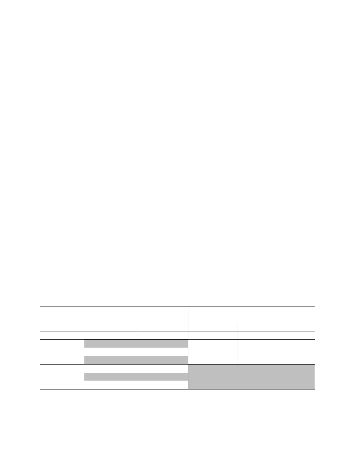
Model
Option B2
Gas Heat
Electric Heat
Input Capacity
Output Capacity
Capacity
MBH
MBH
kW (208V)
kW (230V, 460V, 575V)
1 = Heat 1
60.0
48.0
7.5
10
2 = Heat 2
15.0
20
3 = Heat 3
100.0
80.0
22.5
30
4 = Heat 4
30.0
40
5 = Heat 5
140.0
112.0
6 = Heat 6
7 = Heat 7
160.0
128.0
to the compressor. As the liquid
concentration builds up, oil is washed out of
the compressor, leaving it starved for
lubrication.
The compressor life will be seriously
shorted by reduced lubrication and the
pumping of excessive amounts of liquid oil
and refrigerant.
Note: Low Ambient Operation
Air-cooled DX units without a low ambient
option, such as condenser fan cycling, ECM
driven condenser fans or the 0°F low
ambient option, will not operate in the
cooling mode of operation properly when
the outdoor temperature is below 55°F. Low
ambient and/or economizer options are
recommended if cooling operation below
55°F is expected.
Note: Multiple Units with Multiple
Thermostats
When several heating and cooling units are
used to condition a space all unit thermostat
switches must be set in either heating mode,
cooling mode or off. Do not leave part of the
units switched to the opposite mode.
Cooling only units should be switched off at
the thermostat during the heating season.
Table 1 - Electric and Gas Heating Capacities
Gas or Electric Heating The unit is designed to heat a given amount of air while operating. If this amount of air is greatly reduced, approximately 1/3 during the heating season, the gas heat exchanger or electric heating coil may overheat, and may cut the burner or heater off entirely by action of the safety high temperature limit devices which are factory mounted at the heat exchanger and supply fan areas.
Airflow should be adjusted after installation
to obtain an air temperature rise within the
range specified on the unit rating plate at the
required external static pressure.
Should overheating occur with a gas heat
exchanger, or the gas supply fail to shut off,
shut off the manual gas valve to the furnace
before shutting off the electrical supply.
Prolonged overheating of the heat exchanger
will shorten its life.
If unit has not been selected as a 100%
outside air unit (makeup air unit) the return
air duct must be sealed to the unit and the
return air temperature must be maintained
between 55F and 80F.
26
Page 27

Table 2 - Auxiliary Electric Heating Capacities
Feature 3
kW (208V)
kW (230V, 460V, 575V)
*K = Heat K
7.5
10.0
*L = Heat L
15.0
20.0
*M = Heat M
22.5
30.0
*N = Heat N
30.0
40.0
Unit should not be operated without a
p-trap. Failure to install a p-trap may
result in overflow of condensate
water.
CAUTION
Wiring Diagrams Unit specific wiring diagrams are laminated and affixed inside the compressor and control compartment door.
Condensate Drain Pan Unit requires drain trap to be connected to the condensate drain pan of the unit. Units include one drain pan connection. Condensate drain pipes or p-trap is factory supplied and shipped loose in the control compartment for field installation.
If codes require a condensate drain line, the
line should be the same pipe size or larger
than the drain connection, include a p-trap,
and pitch downward toward drain. An air
break should be used with long runs of
condensate lines.
27
Page 28

Location
Unit Size
2-6 tons
Front -
(Heat Exchanger)
36”
Back - (Outside Air)
36”
Left Side
24”
Right Side
48”
Top
Unobstructed
When locating gas fired units, it is
recommended the unit be installed so
that the flue discharge vents are
located at least 120 inches away
from any opening through which
combustion products could enter the
building.
WARNING
Back
Right Side
Front
Distances from adjacent public
walkways, adjacent buildings,
operable windows and building
openings, shall conform to local
codes and/or the National Fuel Gas
Code, ANSI Z223.1/NFPA 54, or the
National Gas & Propane Code, CSA
B149.1
WARNING
Installation
AAON equipment has been designed for
quick and easy installation.
Unit Location
The curb should be mounted first and must
be located so that duct connections will be
clear of structural members of the building.
Verify rooftop or foundation can support the
total unit weight, including accessory
weights.
Do not position flue opening to discharge
into a fresh air intake of any other piece of
equipment. Unit should also be installed so
that the flow of combustion intake air is not
obstructed from reaching the furnace.
Vent opening must not be blocked by snow.
A minimum 12” curb must be used or the
28
vent outlet shall be greater than 12” off the
ground or roof.
Flue gas is dangerously hot and contains
containments. The user is responsible for
determining if vent gases may degrade
building materials.
The National Gas and Propane Installation
Code, B149.1 specifies a 6 ft. horizontal
vent terminal clearance to gas and electric
meters and relief devices.
Local codes may supersede or further place
restrictions on vent termination locations.
Table 3 - Unit Clearances
Figure 2 - RQ Series Orientation
Setting the Curb Make openings in roof decking large enough to allow for duct penetration and workspace
Page 29

only. Do not make openings larger than
All roofing work should be performed
by competent roofing contractors to
avoid any possible leakage.
CAUTION
Where the supply or warm air duct
passes through a combustible roof, a
clearance of 1 inch must be
maintained between the outside
edges of the duct and combustible
material in accordance with National
Fire Protection Association Standard
No. 90A. Provide flashings or
enclosure between structure and roof
and all joints must be sealed with
mastic roofing to ensure a watertight
seal.
CAUTION
necessary. Set the curb to coincide with the
openings. Make sure the curb is level. Unit
must be level in both horizontal axes to
support the unit and reduce noise and
vibration.
Be careful to install the provided gasket
according to Figure 3 prior to setting the unit
on the curb.
29
Page 30

Figure 3 - RQ Cabinet Standard and Power Exhaust Gasket Locations
30
Page 31

Incorrect lifting can cause damage to
the unit.
CAUTION
Forks
FORKLIFTING
2-6 TON UNITS
Forks or Fork Extensions must be at
least 48” in length and must extend
44” under the unit.
CAUTION
Forklifting the Unit
Units can be lifted using a forklift. Forks
must be 48” in length. Standard units can be
lifted from all sides except the outside air
side. Units with energy recovery wheels can
only be fork lifted from the left or right side.
Forks must be perpendicular to unit. When
lifting from either side, the forks must
extend through to the opposite side of the
unit. When lifting from the end of the unit,
the forks must extend at least 44” under the
unit. When lifting with 48” forks, the back
of the fork must be no more than 4” from the
unit.
Figure 4 - Forklifting an RQ Series Unit from the Side
Figure 5 - Forklifting an RQ Series Unit from the Front
31
Page 32

Lifting the Unit
The RQ Series units must be lifted using the
lifting points in the side base rails. A
spreader bar must be used to prevent the
lifting straps from damaging the unit. The
connection points on the spreader bar must
be 48”-60” apart. The minimum cable
length used to lift a standard length (82”
base length) is 72”. The minimum cable
length to lift energy recovery units (116”
base length) is 96”. The shackles used to
connect the cables to the lifting points in the
base should be ½” nominal size.
The rigging must be adjusted to lift the unit
level. Lifting the unit off-balance may cause
severe damage.
It is recommended to lift the unit with the
outside air hood in the downward shipping
position. However, the unit may be lifted
with the outside air hood in the open
position.
Before lifting unit, be sure that all shipping
material has been removed from unit. Secure
hooks and cables at all lifting points
provided on the unit.
Hoist unit to a point directly above the curb
and duct openings. Be sure that the gasket
material has been applied to curb.
Carefully lower and align the unit with
utility and duct openings. Lower the unit
until the unit skirt fits around the curb. Some
units are designed to overhang the curb.
Take care that any recessed base rails fit
around the curb. Make sure the unit is
properly seated on the curb and is level.
32
Figure 6 - Lifting Details of a 2-6 ton Standard or Power Exhaust Unit
Page 33

Figure 7 - Lifting Details of a 2-6 ton Energy Recovery Wheel Unit
33
Page 34

Do not drill or punch holes in the
base of the unit, from inside the unit
or from below the unit to attach
ductwork. Leaking may occur if unit
base is punctured.
CAUTION
Vertical Duct Connection
Note: If outside air will be in contact with
the air tunnel base the unit should include
the base insulation option or the base must
be field insulated.
34
Figure 8 - Vertical Duct Connection
Page 35

Seismic Curb Installation
Using a standard curb with a seismic unit
will void the certification of the unit. All
mounting details listed must be followed to
achieve seismic certification. The AAON
unit must be certified to ICC-ES AC156
when using a seismic curb for seismic
certifications to apply. Any deviations or
modifications to the unit or curb will void all
seismic certification.
Structural engineer of record must approve
building anchorage to unit or curb in
compliance with OSP-0180-10. Use
provided self tapping screws to attach base
of unit to seismic curb bracket.
Figure 9 - Solid Bottom Seismic Curb with Filters
35
Page 36

Figure 10 - Seismic Solid Bottom Curb without Filters Cross Section
36
Figure 11 - Seismic Solid Bottom Curb without Filters Detail A
Figure 12 - Seismic Solid Bottom Curb without Filters Detail B
Page 37

Figure 13 - Seismic Rigid Mount Curb Cross Section
Return
Supply
Horizontal Duct Connection
Note: If outside air will be in contact with
the air tunnel base the unit should include
the base insulation option or the base must
be field insulated.
Remove shipping covers and attach duct to
flanges provided on the unit. The installer is
responsible for sealing ducts to the flanges
to prevent water leaks.
Remove the two screws at the bottom of the
rain hood that secure it in the shipping
position. Remove the screws that attach the
side pieces of the hood to the top of the
hood.
Rotate the side pieces so that the holes along
one edge line up with the holes on the top
piece and the flange is on the inside of the
rain hood.
Attach the side pieces to the top of the hood
using the provided screws and attached the
side pieces to the end of the unit through the
flange.
Apply silicon caulking along the top and
both sides of the rain hood. Take care to seal
the top corners where the rain hood attaches
to the unit.
Figure 14 - Horizontal duct connections
Outside Air Rain Hood Rain hood must be opened before startup of the unit. Fresh air intake adjustments should be made according to building ventilation or local code requirements.
37
Page 38

Figure 15 - RQ Series unit Closed Rain
Hood
Metal Mesh Filters Metal mesh outside air filters require installation of the filter rack on the intake of the rain hood.
Figure 16 - RQ Series unit Open Rain Hood
Clips which hold the metal mesh filters in
the filter rack should face outward.
38
Figure 17 - Rain Hood with Metal Mesh Filter Rack Installation
Page 39

Electrical
Figure 19 - Back View of Power Switch from Control Compartment
Electric shock hazard. Before
attempting to perform any installation,
service, or maintenance, shut off all
electrical power to the unit at the
disconnect switches. Unit may have
multiple power supplies. Failure to
disconnect power could result in
dangerous operation, serious injury,
death, or property damage.
WARNING
Utility Entry
Field
Connection
Location
Verify the unit nameplate agrees with power
supply. Connect power and control wiring to
the unit as shown in Figure 12 and in the
unit specific wiring diagram, which shows
factory and field wiring and is attached to
the inside of the door of the control
compartment.
Route power and control wiring, separately,
through the utility entry in the base of the
unit. Do not run power and control signal
wires in the same conduit. The utility entry
is located in the unit base in the front right
hand corner of the unit (compressor
compartment). See unit drawing for specific
location.
Figure 18 - Unit Base Utility Entry
Size supply conductors based on the unit
MCA rating. Supply conductors must be
rated a minimum of 75°C.
Protect the branch circuit in accordance with
code requirements. The unit must be
electrically grounded in accordance with
local codes, or in the absence of local codes,
39
Page 40

Rotation must be checked on all
MOTORS AND COMPRESSORS of
three phase units. Supply fan,
exhaust fan, and condenser fan
motors should all be checked by a
qualified service technician at startup
and any wiring alteration should only
be made at the unit power
connection.
CAUTION
Scroll compressors are directional
and will be damaged by operation in
the wrong direction. Low pressure
switches on compressors have been
disconnected after factory testing.
Rotation should be checked by a
qualified service technician at startup
using suction and discharge pressure
gauges and any wiring alteration
should only be made at the unit
power connection.
CAUTION
Three phase voltage imbalance will
cause motor overheating and
premature failure.
CAUTION
the current National Electric Code,
ANSI/NFPA 70 or the current Canadian
Electrical Code CSA C22.1.
Note: All units are factory wired for 208V,
230V, 460V, or 575V. The transformer
configuration must be checked by a
qualified technician prior to service,
especially if unit is to be connected to a
208V or 230V supply. For 208V service
interchange the yellow and red conductor on
the low voltage control transformer.
Red-Black for 208V
Yellow-Black for 230V
Wire power leads to the unit’s terminal
block or main disconnect. All wiring beyond
this point has been completed by the
manufacturer and cannot be modified
without effecting the unit’s agency/safety
certification.
Supply voltage must be within the min/max
range shown on the unit nameplate.
Available short circuit current should not
exceed the short circuit current rating
(SCCR) shown on the unit nameplate.
Three phase voltage imbalance will cause
motor overheating and premature failure.
The maximum allowable imbalance is 2.0%.
Voltage imbalance is defined as 100 times
the maximum deviation from the average
voltage divided by the average voltage.
40
Example:
(221V+230V+227V)/3 = 226V, then
100*(226V-221V)/226V = 2.2%, which
exceeds the allowable imbalance.
Check voltage imbalance at the unit
disconnect switch and at the compressor
terminal. Contact your local power company
for line voltage corrections.
Installing contractor must check for proper
motor rotation and check blower motor
amperage listed on the motor nameplate is
not exceeded. Motor overload protection
may be a function of the variable frequency
drive and must not be bypassed.
Page 41

Wire control signals to the unit’s low
Wire Size (Stranded)
- Copper Conductors
Only
Total Wire Distance
Allowable
20 AWG
200 ft
18 AWG
350 ft
16 AWG
500 ft
14 AWG
750 ft
12 AWG
1250 ft
Model
Option
B2
Input
MBH
Connections
Quantity
Size
1
60.0
1
1/2”
3
100.0
5
140.0
7
160.0
FOR YOUR SAFETY
Read the entire gas heating
installation section of this manual
before beginning installation of the
gas heating section.
If you do not follow these instructions
exactly, a fire or explosion may result
causing property damage, personal
injury, or loss of life.
WARNING
voltage terminal block located in the
controls compartment.
If any factory installed wiring must be
replaced, use a minimum 105°C type AWM
insulated conductors.
Thermostat Control Wiring
If a thermostat is used for unit control,
thermostat should be located on an inside
wall 4-5 feet above the floor where it will
not be subjected to drafts, sun exposure, or
heat from electrical fixtures of appliances.
Control wiring must deliver adequate
voltage to components to assure proper
operation. Control voltage returning from
controller circuit must be a minimum of 21
VAC. To assure proper wiring use the
following chart to determine the allowable
wiring distances.
Table 4 - Control Wiring
Take the total wire distance allowable and
divide by the number of wires to be
connected. This indicates the distance
allowable for that size wire. The wiring to
the unit must not exceed the total wire
distance allowable. If the voltage at the
connectors is less than 21 VAC, isolation
relays must be installed. If under external
control 21 VAC must be field verified.
All external devices must be powered via a
separate external power supply.
Example:
A total of 8 wires must be pulled 75ft to
control the unit. What size wire should be
used?
According to the Table 3, 16 AWG allows
for 63ft (500 ft/8 wires) and 14 AWG allows
for 94ft (750 ft/8 wires). Thus, 14 AWG
should be used.
Gas Heating
Verify the unit nameplate agrees with the
proper gas supply type and amount.
Gas piping must be installed in accordance
with local codes, or in the absence of local
codes, installation must conform to the
current (United States) National Fuel Gas
Code ANSI-Z223.1/NFPA 54 or the current
(Canada) National Fuel & Propane
Installation Code CSA B149.1 or B149.2.
Table 5 - 2-6 ton Gas Connections
41
Page 42

Pipe Size
Length of Pipe
20 ft
50 ft.
100 ft.
150 ft.
200 ft.
1/2”
120
73
50
40
35
3/4”
250
151
103
84
72
1”
465
285
195
160
135
1-1/4”
950
580
400
325
280
1-1/2”
1460
900
620
500
430
2”
2750
1680
1150
950
800
2-1/2”
4350
2650
1850
1500
1280
Pipe Size
Length of Pipe
20 ft
50 ft.
100 ft.
150 ft.
200 ft.
1/2”
189
114
78
63
55
3/4”
393
237
162
132
112
1”
732
448
307
252
213
1-1/4”
1496
913
630
511
440
1-1/2”
2299
1417
976
787
675
2”
4331
2646
1811
1496
1260
Btu
ft
MBH
1000
1080
3
After verifying gas inlet pressure and
manifold pressure the service technician
must time the gas flow rate through the gas
meter with a stopwatch to verify the gas
input rate.
Unit nameplate input rate value has been
calculated at the altitude where the unit was
shipped. Above 2,000 ft the input rate is
adjusted 4% for every 1,000 ft.
Maximum Piping Capacities
Table 6 - Natural Gas (ft3/hr)
- Specific Gravity = 0.6, Supply Pressure ≤ 0.5 psi, Pressure Drop = 0.5” w.c.
Figure 20 - RQ Series Gas Heat Exchanger
Table 7 - Propane (kBtu/hr)
- Specific Gravity = 1.52, Supply Pressure = 11” w.c., Pressure Drop, 0.5” w.c.
Do not use gas piping smaller than unit gas
connections. Natural gas pipe runs longer
than 20 feet and propane gas pipe runs
longer than 50 feet may require a larger
supply pipe than the unit connection size.
Some utility companies may also require
pipe sizes larger than the minimum sizes
listed.
Piping Sizing Examples A 100 ft pipe run is needed for a 1080 MBH natural gas heater. The natural gas has a rating of 1000 Btu/ft3 and a specific gravity of 0.6 (Obtain these values from the local gas supplier.)
1080 ft3/hr
42
Page 43

From the natural gas maximum capacities
Pipe Size
Support Intervals
1/2” to 3/4”
Every 6 ft
3/4” to 1”
Every 8 ft
1-3/4” or Larger
(Horizontal)
Every 10 ft
1-1/4” or Larger
(Vertical)
Every Floor
Heater should be disconnected from
the gas supply piping during pressure
testing of the supply piping system
with pressures in excess of ½ psi. Gas
valves can be damaged if subjected to
more than ½ psi.
CAUTION
table, at 100 ft and 1080 ft3/hr the required
minimum pipe size is 2”.
A 100 ft pipe run is needed for a 270 MBH
propane gas heater.
270 MBH = 270 kBtu/hr
From the propane gas maximum capacities
table, at 100 ft and 270 kBtu/hr the required
minimum pipe size is 1”.
Inlet and Manifold Pressures For natural gas units, the minimum inlet gas pressure to the unit is 6” w.c. and maximum inlet gas pressure to the unit is 10.5” w.c. For propane units, the minimum inlet gas
pressure to the unit is 11” w.c. and the
maximum inlet gas pressure to the unit is
13” w.c. A field provided 1/8” NPT pressure
tap is required to be installed in the piping
just upstream of the shutoff valve for test
gage connection to allow checking of the
gas supply pressure at the unit.
A factory installed pressure tap on the outlet
end of the gas valve can be used to verify a
manifold pressure of 3.5” w.c. for natural
gas, or 10.5” w.c. for propane.
For two stage gas valves, the low stage
setting should be set at 1.1” w.c. for natural
gas, 5.0” w.c. for propane. For modulating
heaters, the safety shut-off valve would be
set following the instructions above, then
from a provided pressure tap in the gas train
immediately preceding the burner manifold
the modulating valve is set to maintain a
maximum of 3.5” w.c. and a minimum of
0.4” w.c.
Gas Pressure Regulator & Overpressure Protection Device
A gas pressure regulator must be installed if
natural gas supply pressure to the unit is
greater than 10.5” w.c. and less than 2 psi
(55.4” w.c.) and if propane gas supply
pressure is greater than 13” w.c. and less
than 2 psi (55.4” w.c.). Regulators must
comply with the latest edition of the
Standard for Line Pressure Regulators,
ANSI Z21.80/CSA 6.22.
Both a gas pressure regulator and
overpressure protection device (OPD) must
be installed if gas supply pressure to the unit
is greater than 2 psi (55.4” w.c.) and less
than 5 psi (138.4” w.c.), in compliance with
ANSI Z21.80/CSA 6.22. For proper heater
operation, pressure to the regulator MUST
NOT be greater than 5 psi (138.4” w.c.).
Piping Supports
Gas supply piping must be supported
directly at the connection to the unit and at
intervals listed in the following table with
metal straps, blocks, or hooks. Piping should
not be strained or bent.
Table 8 - Gas Piping Supports
43
Page 44

Additional Gas Piping Considerations Local codes will usually require a field provided and installed manual main shutoff valve and union external to the unit. Main shutoff valve should be labeled. A drip leg should be installed near the unit connection to trap sediment and condensate. Pipe joint compounds used on all gas piping connections should be resistant to liquid petroleum gases. If flexible gas piping to the unit, or in the unit, must be replaced connectors cannot be reused, only new connectors may be used.
Heat exchanger comes equipped with a
condensate drain which should be plumbed
to the appropriate drain according to the
(United States) National Fuel Gas Code
ANSI-Z223.1/NFPA 54 or the current
(Canada) National Fuel & Propane
Installation Code CSA B149.1 or B149.2,
the International Building Code, and any
applicable local and regional codes and
regulations.
The condensate drain connection is located
next to the gas entry location. The heat
exchanger condensate drain connection from
the unit is a 5/8” barbed nylon elbow
connection.
Figure 21 - Example 2-6 ton through the Base Gas Piping
44
Page 45

Leak Testing
Do not use open flame or other
source of ignition for leak testing. Fire
or explosion could result causing
property damage, personal injury, or
death.
DANGER
LEAK CHECK GAS PIPE
The gas pipe in the unit should be
checked for leaks before startup.
Leak checking is the responsibility of
the installing contractor. All
connections should be checked for
leaks annually after installation.
Failure to leak check could result in
fire, explosion, or other hazardous
situations.
DANGER
Some soaps used for leak detection
can be corrosive to certain metals.
Rinse piping thoroughly after leak
test has been completed.
CAUTION
Those sensitive to odors or gases
from trace amounts of residual oils
should NOT be present in the
conditioned space during the startup
of a gas fired installation.
WARNING
OPEN LOOP APPLICATIONS
Failure of the condenser as a result
of chemical corrosion is excluded
from coverage under AAON Inc.
warranties and the heat exchanger
manufacturer’s warranties.
WARNING
All components of gas supply system,
including manual shut off valves and the
piping in the interior of the unit, should be
leak tested with a soap solution before
operating the appliance and at least on an
annual basis thereafter.
All gas fired heat exchangers are completely
tested at the factory before shipment. This
will remove nearly all of the oils that have
been used in the manufacturing process.
However, trace amounts may remain. When
performing the initial startup at the jobsite, it
is highly recommended that people or any
other living animals, which may be sensitive
to the residual odors or gases, NOT be
present in the conditioned space during the
startup. In all cases, including the initial
factory firing and testing, any of the gases
will be under the acceptable level of
concentration for human occupancy.
Refrigerant-to-Water Heat Exchanger
Condenser water pump, condenser water
piping, cooling tower or geothermal loop,
pressure gauges, strainers, piping insulation
and all components of the waterside piping
must be field installed.
Open Loop Applications
This product contains one or more
refrigerant-to-water heat exchangers made
of copper, which is subject to corrosion and
failure when exposed to chlorides.
Do not allow water containing any form of
chlorides to enter this heat exchanger.
45
Page 46

OPEN LOOP APPLICATIONS
Cupronickel refrigerant-to-water heat
exchangers are recommended with
all open loop applications. Failure to
use a Cupronickel heat exchanger
may result in premature failure of
your system and possible voiding of
the warranty.
WARNING
Cleaning the cooling tower or
condenser water loop with harsh
chemicals such as hydrochloric acid
(muriatic acid), chlorine or other
chlorides, can damage the
refrigerant-to-water heat exchanger.
Care should be taken to avoid
allowing chemicals to enter the
refrigerant-to-water heat exchanger.
See Appendix A - Heat Exchanger
Corrosion Resistance for more
information.
CAUTION
Common forms of chlorides include:
1. Sea water mist entering an open cooling
tower system.
2. Contaminated make-up water containing
salt water.
3. Disinfecting the water loop with solutions
containing sodium hypochlorite.
Chlorides will result in a premature failure
of the condenser.
Failure of the condenser as a result of
chemical corrosion is excluded from
coverage under AAON warranties and the
heat exchanger manufacturer warranties.
Failure of the condenser will allow water to
enter the refrigerant circuit and will cause
extensive damage to the refrigerant circuit
components. Any damage to the equipment
as a result of condenser failure from
chemical corrosion due to the fluid in the
condenser is excluded from coverage under
AAON warranties and the heat exchanger
manufacturer warranties.
46
Freezing Water in the Heat Exchanger This product contains one or more refrigerant-to-water heat exchangers. A refrigerant-to-water heat exchanger contains refrigerant in one passage and water in another passage. Water is subject to freezing at 32°F. When water freezes in a heat exchanger significant forces are exerted on the components of the heat exchanger where the water is confined.
Failure of the condenser due to freezing will
allow water to enter the refrigerant circuit
and will cause extensive damage to the
refrigerant circuit components. Any damage
to the equipment as a result of water
freezing in the condenser is excluded from
coverage under AAON warranties and the
heat exchanger manufacturer warranties.
Unit is capable of operating with Entering
Water Temperatures (EWT) as low as 57°F,
during the cooling mode, without the need
for head pressure control. If the EWT is
expected to be lower than 57°F or a more
stable operation is desired, a factory
provided head pressure control water valve
option is available.
Page 47

% Glycol
Ethylene
Glycol
Propylene
Glycol
20
18°F
19°F
30
7°F
9°F
40
-7°F
-6°F
50
-28°F
-27°F
Model (RQ-)
Supply and Return
Connection Size
002
3/4” Sweat
003, 004, 005, 006
1” Sweat
WATER PRESSURE
Prior to connection of condensing
water supply, verify water pressure is
less than maximum pressure shown
on unit nameplate. To prevent injury
or death due to instantaneous
release of high pressure water, relief
valves should be field supplied on
water piping. Supply water
connection may require a backflow
preventer to prevent supply makeup
water from backing up into the public
water system.
WARNING
WATER FREEZING
Failure of the condenser due to
freezing will allow water to enter the
refrigerant circuit and will cause
extensive damage to the refrigerant
circuit components. Any damage to
the equipment as a result of water
freezing in the condenser is excluded
from coverage under AAON
warranties and the heat exchanger
manufacturer warranties.
WARNING
PVC (Polyvinyl Chloride) and CPVC
(Chlorinated Polyvinyl Chloride) are
vulnerable to attack by certain
chemicals. Polyolester (POE) oils
used with R-410A and other
refrigerants, even in trace amounts,
in a PVC or CPVC piping system will
result in stress cracking of the piping
and fittings and complete piping
system failure.
Glycol solution should be used if ambient
temperatures are expected to fall below
freezing or if the loop entering water
temperature to the unit is below 50°F while
operating in the heating mode (heat pump
units only). Adding glycol to condenser water
causes an increase in pressure drop and also
results in a decrease in unit performance. A
minimum concentration of 20% glycol
solution is recommended.
Table 9 - Glycol Freezing Points
Water loop piping that runs through
unheated areas or outside the building
should be insulated.
Water Piping Installing contractor must ensure a differential pressure switch or water flow switch is installed between the condenser water supply and return connections. This sensor provides a signal to the unit controller that water flow is present in the
refrigerant-to-water heat exchanger and the
unit can operate without damaging unit
components.
Table 10 - Condenser Water Connections
Only use approved water pipe material.
Avoid using galvanized material for water
lines/fittings as the material is corrosive and
may cause fouling of the water system.
47
Page 48

WATER PIPING
Follow national and local codes when
installing water piping. Connections
to the unit should incorporate
vibration eliminators to reduce noise
and vibration and shutoff valves to
facilitate servicing. Supply and return
water piping must be at least as large
as the unit connections and larger
depending on length of runs, rise and
bends.
CAUTION
Each heat exchanger is equipped
with a refrigerant pressure relief
device to relieve pressure should
excessive condensing pressures
(>675 psig) occur. Codes may
require installing contractor to
connect and route relief piping
outdoors. The relief valve has a 5/8”
male flare outlet connection.
CAUTION
Installing contractor is responsible for
properly sizing and installing water
system components. Improper fluid
flow due to valves, piping, or
improper pump operation may result
in unacceptable unit operation and
void warranty.
CAUTION
Condenser water pump must be field sized
and installed between the cooling
tower/geothermal loop and self-contained
unit. System should be sized in accordance
with the ASHRAE Handbook. Use
engineering guidelines to maintain equal
distances for supply and return piping and
limit bend radiuses to maintain balance in
the system. Balancing valves, permanent
thermometers and gauges may be required.
Before connection to the unit the condenser
water system should be flushed to remove
foreign material that could cause condenser
fouling. Install a screen strainer with a
minimum of 20 Mesh ahead of the
condenser inlet to prevent condenser fouling
and internal tube damage.
Mineral content of the condenser water must
be controlled. All make-up water has
minerals in it and as the water is evaporated
in the cooling tower, these minerals remain.
As the mineral content of the water
increases, the conductivity of the water
increases.
Field provided and installed water treatment
program must be compatible with stainless
steel, copper, aluminum, ABS plastic, and
PVC. Batch feed processes should never be
48
used as concentrated chemicals can cause
corrosion. Never use hydrochloric acid
(muriatic acid) or chlorine as it will corrode
stainless steel.
NOTE: Ball valves should be installed in
the condenser water supply and return lines
for unit isolation and water flow balancing.
All manual flow valves should be of the ball
valve design. Globe or gate valves should
not be used due to high pressure drops and
poor throttling characteristics.
Pressure and temperature ports are
recommended in condenser water supply
and return lines for system balancing. These
openings should be 5 to 10 pipe diameters
from the unit water connections. To allow
for mixing and temperature stabilization,
wells in the water piping should extend at
least ½ pipe diameter into the pipe.
Page 49

Piping systems should not exceed 10 ft/sec
Unit should not be operated without a
p-trap. Failure to install a p-trap may
result in overflow of condensate
water into the unit.
CAUTION
fluid velocity to ensure tube wall integrity
and reduce noise.
Condensate Drain Piping
2-6 ton units are equipped with one
condensate drain pan connection, on the
right side of the unit, and are furnished with
a p-trap for field installation.
All drain connections must be used and
individually trapped to ensure a minimum
amount of condensate accumulation in the
drain pans. ABS type cement should be used
to join the drain pipe connections.
Drainage of condensate directly onto the
roof may be acceptable in certain areas, refer
to local codes. If condensate is to drain
directly onto the roof a small drip pad
should be placed below the drain to protect
the roof from possible damage.
If condensate is piped into the building
drainage system, the drain pipe should
penetrate the roof external to the unit itself.
The drain line should be pitched away from
the unit at least 1/8 inch per foot. On longer
runs an air break should be used to ensure
proper drainage.
Draw-through cooling coils will have a
negative static pressure in the drain pan area.
This will cause an un-trapped drain to back
up due to air being pulled up through the
condensate drain piping.
Condensate drain trapping and piping should
conform to all applicable governing codes.
Discharge and Suction Line Piping There are two different locations to pipe out of the unit, the post corner hole location and the post back hole location. The post corner hole location is to run pipe along the roof and then down by the disconnect switch (Figure 22 and Figure 24). The post back hole location is to run the pipe along the roof, back across the coil, and come out near the blower access panel (Figure 23 and Figure 25).
When drilling the holes, use a 1 ¼ inch hole
for the suction line and a 1 inch hole for the
liquid line (Figure 22 and Figure 23). For
pipe sizing, refer to appropriate guidelines in
the condenser or condensing unit installation
manual. The grommets will help seal in
between the holes in the sheet metal and the
piping. If you are piping through the back
post foam panel, attach grommet to the
inside skin of the foam part. If you are
piping through post corner hole location, use
caution around electrical wires. You will
need to turn off power to the unit.
49
Page 50

Figure 22 - Post Corner Hole Location
50
Figure 23 - Post Back Hole Location
Page 51

Figure 24 - Post Corner Hole Piping
Figure 25 - Post Back Hole Piping
51
Page 52

Model (RQ-)
Hot Water Coil
Connection Size
002-006
7/8”
Model (RQ-)
Steam Coil Connection
Size
002-006
2 1/8” (standard coil)/
1 1/8” (preheat coil)
Model (RQ-)
Chilled Water Coil
Connection Size
002-006
7/8”
Piping shall be in accordance with
national and local codes. Pressure
limiting devices, backflow preventers
and all other safety requirements are
the sole responsibility of the installing
contractor.
WARNING
Heating Coils One or two row hot water and steam heating and preheating coils can be factory installed. All valve controls for heating operation are field supplied and field installed. Hot water and steam coil connections are spun copper tube.
Water coils should not be subjected to
entering air temperatures below 38°F to
prevent coil freeze-up. If air temperature
across the coil is going to be below this
value, use a glycol solution to match the
coldest air expected.
Table 11 - Hot Water Coil Connection Sizes
Table 12 - Steam Coil Connection Sizes
Chilled Water Coil
Four or six row chilled water cooling coils
can be factory installed. All valve controls
for cooling operation are field supplied and
field installed. Chilled water coil
connections are spun copper tube.
Table 13 - Chilled Water Coil Connection
Sizes
52
Page 53

Startup
Electric shock hazard. Shut off all
electrical power to the unit to avoid
shock hazard or injury from rotating
parts.
WARNING
Improper installation, adjustment,
alteration, service or maintenance
can cause property damage,
personal injury or loss of life. Startup
and service must be performed by a
Factory Trained Service Technician.
WARNING
Before completing startup and
leaving the unit a complete operating
cycle should be observed to verify
that all components are functioning
properly.
CAUTION
The Clean Air Act of 1990 bans the
intentional venting of refrigerant
(CFC’s and HCFC’s) as of July 1,
1992. Approved methods of recovery,
recycling or reclaiming must be
followed. Fines and/or incarceration
may be levied for non-compliance.
CAUTION
(See back of the manual for startup form.)
During startup, it is necessary to perform
routine checks on the performance of the
unit. This includes checking the air flow, air
filters, condenser water flow, dampers,
heaters, and refrigerant charge.
Filters Do not operate the unit without filters in place. Unit should be checked for correct filter placement during startup. Operation of the equipment without filters will result in a clogged evaporator coil.
Adjusting Refrigerant Charge Adjusting the charge of a system in the field must be based on determination of liquid sub-cooling and evaporator superheat. On a system with a TXV liquid sub-cooling is more representative of the charge than evaporator superheat but both measurements must be taken.
Before Charging
Unit being charged must be at or near full
load conditions before adjusting the charge.
Units equipped with hot gas reheat must be
charged with the hot gas reheat valves
closed while the unit is in cooling mode to
get the proper charge. After charging, unit
should be operated in reheat
(dehumidification) mode to check for
correct operation.
Units equipped with heat pump options
should be charged in heating mode to get the
proper charge. After charging, unit should
be operated in cooling mode to check for
correct charge. Charge may need to be
adjusted for cooling mode. If adjustments
are made in the cooling mode, heating mode
must be rerun to verify proper operation.
After adding or removing charge, the system
must be allowed to stabilize, typically 10-15
minutes, before making any other
adjustments.
53
Page 54

Air-Cooled Cond./Air-Source Heat Pump
Sub-Cooling
12-18°F
Sub-Cooling with
Hot Gas Reheat
15-22°F
Superheat
8-15°F
Water-Cooled Cond./Water-Source Heat
Pump
Sub-Cooling
4-8°F
Superheat
8-15°F
DO NOT OVERCHARGE!
Refrigerant overcharging leads to
excess refrigerant in the condenser
coils resulting in elevated compressor
discharge pressure.
CAUTION
Thermal expansion valve must be
adjusted to approximately 8-15°F of
suction superheat. Failure to have
sufficient superheat will damage the
compressor and void the warranty.
CAUTION
The type of unit and options determine the
ranges for liquid sub-cooling and evaporator
superheat. Refer to Table 13 below when
determining the proper sub-cooling.
Checking Liquid Sub-Cooling Measure the temperature of the liquid line as it leaves the condenser coil.
Read the gauge pressure at the liquid line
close to the point where the temperature was
taken. You must use liquid line pressure as it
will vary from discharge pressure due to
condenser coil pressure drop.
Convert the pressure obtained to a saturated
temperature using the appropriate refrigerant
temperature-pressure chart.
Subtract the measured liquid line
temperature from the saturated temperature
to determine the liquid sub-cooling.
Compare calculated sub-cooling to Table 14
for the appropriate unit type and options.
Checking Evaporator Superheat Measure the temperature of the suction line close to the compressor.
Read gauge pressure at the suction line close
to the compressor.
Convert the pressure obtained to a saturated
temperature using the appropriate refrigerant
temperature-pressure chart.
Subtract the saturated temperature from the
measured suction line temperature to
determine the evaporator superheat.
Compare calculated superheat to the table
below for the appropriate unit type and
options.
54
Table 14 - Acceptable Refrigeration Circuit
Values
Adjusting Sub-Cooling and Superheat Temperatures
The system is overcharged if the sub-cooling
temperature is too high and the evaporator is
fully loaded (low loads on the evaporator
result in increased sub-cooling) and the
evaporator superheat is within the
temperature range as shown in the table
above (high superheat results in increased
sub-cooling).
Correct an overcharged system by reducing
the amount of refrigerant in the system to
lower the sub-cooling.
Page 55

The system is undercharged if the superheat
is too high and the sub-cooling is too low
Correct an undercharged system by adding
refrigerant to the system to reduce superheat
and raise sub-cooling.
If the sub-cooling is correct and the
superheat is too high, the TXV may need
adjustment to correct the superheat.
55
Page 56

°F
PSIG
°F
PSIG
°F
PSIG
°F
PSIG
°F
PSIG
20
78.3
47
134.7
74
213.7
101
321.0
128
463.2
21
80.0
48
137.2
75
217.1
102
325.6
129
469.3
22
81.8
49
139.7
76
220.6
103
330.2
130
475.4
23
83.6
50
142.2
77
224.1
104
334.9
131
481.6
24
85.4
51
144.8
78
227.7
105
339.6
132
487.8
25
87.2
52
147.4
79
231.3
106
344.4
133
494.1
26
89.1
53
150.1
80
234.9
107
349.3
134
500.5
27
91.0
54
152.8
81
238.6
108
354.2
135
506.9
28
92.9
55
155.5
82
242.3
109
359.1
136
513.4
29
94.9
56
158.2
83
246.0
110
364.1
137
520.0
30
96.8
57
161.0
84
249.8
111
369.1
138
526.6
31
98.8
58
163.8
85
253.7
112
374.2
139
533.3
32
100.9
59
166.7
86
257.5
113
379.4
140
540.1
33
102.9
60
169.6
87
261.4
114
384.6
141
547.0
34
105.0
61
172.5
88
265.4
115
389.9
142
553.9
35
107.1
62
175.4
89
269.4
116
395.2
143
560.9
36
109.2
63
178.4
90
273.5
117
400.5
144
567.9
37
111.4
64
181.5
91
277.6
118
405.9
145
575.1
38
113.6
65
184.5
92
281.7
119
411.4
146
582.3
39
115.8
66
187.6
93
285.9
120
416.9
147
589.6
40
118.1
67
190.7
94
290.1
121
422.5
148
596.9
41
120.3
68
193.9
95
294.4
122
428.2
149
604.4
42
122.7
69
197.1
96
298.7
123
433.9
150
611.9
43
125.0
70
200.4
97
303.0
124
439.6
44
127.4
71
203.6
98
307.5
125
445.4
45
129.8
72
207.0
99
311.9
126
451.3
46
132.2
73
210.3
100
316.4
127
457.3
Table 15 - R-410A Refrigerant Temperature-Pressure Chart
56
Page 57

Gas Heater Instructions
Figure 26 - Gas Heater Instructions
57
Page 58

Supply Fan EC Motor Startup
Figure 27 - PIN Connectors on EC Supply Fan Motor Electronics
Speed adjustment is made by varying the
DC voltage on pin 8 (+) & 16 (-). If
WattMaster, Mini Controller, or JENEsys
control systems are installed on the system
then they will provide the 0-10VDC signal
for speed control. The controller will be
wired directly to pin 8 & 16. If a
potentiometer is installed in the unit, the
10VDC output of the motor electronics will
be wired through the potentiometer and then
58
back into pin 8 & 16 for speed control. By
adjusting the potentiometer from 0-100%
you can manually adjust the speed of the
motor.
If the rotation direction is wrong, check the
brown wire on the control connector and
ensure that it is connected from pin 13 to pin
11. Making/Breaking this wire changes the
rotation of the motor.
Page 59

If there is no rotation and/or no speed
Color
Terminal
Customer
Connection
Option 1
Option 2
Option 3
Option 4
Option 5
Black
0.50 BWS
L1
208-230 VAC
208-230 VAC
208-230 VAC
208-230 VAC
208-230 VAC
Brown
0.50 BWS
L2
208-230 VAC
208-230 VAC
208-230 VAC
208-230 VAC
208-230 VAC
Green
#10
EYELET
Ground
GND
GND
GND
GND
GND
Blue
0.50 BWS
Common
Common
24 VAC
24 VAC
24 VAC
24 VAC
Yellow
0.50 BWS
Signal
PWM
24 VAC
24 VAC
White
0.50 BWS
Signal 24 VAC
24 VAC
Orange
0.50 BWS
Signal
24 VAC
24 VAC
RPM
300-1100
300
500
850
1100
Rotation
CCW
CCW
CCW
CCW
CCW
ECM Toolbox ID
Variable
Speed 4
Speed 3
Speed 2
Speed 1
20% PWM RPM
300
100% PWM RPM
1100
change, try the following:
1. Check the line-to-line voltage on the
fuse block connected to the supply fan
motor and ensure it is between 187VAC
to 264VAC
2. Turn the potentiometer to 50%
3. Energize the BC relay by making a
blower call.
4. Check DC voltage on S1 (-) and S2 (+),
0-10VDC signal on S1 & S2 sets the
speed of the motor – thus 0VDC is no
speed and 10VDC is full speed.
5. If DC Voltage is present on S1 & S2
then ensure that BC (blower relay) is
energized and is passing the DC voltage
through to the motor. If BC is not
energized then check wiring for 24VAC
blower call.
6. If no DC voltage is present on S1 & S2
then check S1 (-) & S3 (+), this is the
+10VDC output from the motor that is
supplied to the Potentiometer for speed
control.
If the following troubleshooting suggestions
do not solve the issue, contact AAON for
assistance.
Table 16 - EC Condenser Fan Cycling Options
Condenser Fan EC Motor Startup The fan cycling option uses a fan cycle switch to switch between one of the discrete speed inputs (see Table 16) on the motor thus cycling between two preset speeds based upon discharge pressure of the unit. By connecting 24VAC to a single or combination of the yellow, white, or orange wires, the motor will run at the discrete speeds in Table 12.
WattMaster Condenser Head Pressure
Module is used for variable speed control of
the motor to maintain a head pressure. The
motor should be factory wired to the PWM
outputs of the WattMaster Condenser Head
Pressure Module. See WattMaster literature
for further information
(http://www.orioncontrols.com).
Note
High voltage wires out of the motor:
Black & Brown – 1 Phase Line Voltage
Green - Ground
Low control voltage wires out of the motor:
Blue – Common
Yellow – Variable Speed Control
59
Page 60

COMPRESSOR CYCLING
5 MINUTE MINIMUM OFF TIME
To prevent motor overheating
compressors must cycle off for a
minimum of 5 minutes.
5 MINUTE MINIMUM ON TIME
To maintain the proper oil level
compressors must cycle on for a
minimum of 5 minutes.
The cycle rate must not exceed 6
starts per hour.
WARNING
Operation
Unit operations should be controlled with
thermostat, or unit controller, never at the
main power supply, except for servicing,
emergency, or complete shutdown of the
unit.
Thermostat Operation Heating Thermostat system switch - "Heat" Thermostat fan switch - "Auto" or "On" Thermostat temperature set to desired point.
Cooling
Thermostat system switch - "Cool"
Thermostat fan switch - "Auto" or "On"
Thermostat temperature set to desired point.
Air Circulation
Thermostat system switch - "Off"
Thermostat fan switch - "Auto" or "On"
No change of the thermostat temperature.
With these settings, the supply blower will
run continuously but the supply air will not
be heated, cooled, or dehumidified.
System Off
Thermostat system switch - "Off"
Thermostat fan switch - "Auto"
No change of the thermostat temperature.
With these settings the system is shut down,
with the exception of control system power.
Night and Weekend Unoccupied Operation
To reduce the operating time of the unit
when the space is unoccupied, such as nights
and weekends, it is recommended that the
temperature setting be raised about 5°F
while unoccupied during the cooling season
and lowered about 10°F during the heating
season.
60
Packaged DX Cooling Operation and Control
When a call for cooling (G and Y1, Y2, etc.)
is made the supply blower motors and
compressors will energize.
Gas Heater Operation When heat (G and W1, W2, etc.) is called for the combustion motor starts and the ignition control is energized. The control sends 24 VAC to the main gas valve and high voltage to the igniter. If a burner flame has been detected within 10 seconds, the spark is extinguished and the flame continues. If a flame has not been detected after 10 seconds, the gas valve closes, the spark ceases and the induced draft blower continues to purge the heat exchanger. After 45 seconds of purge, the ignition system will attempt to light the burners again. Should no flame be detected after 3 tries, the ignition control will lock out the system. Power to the ignition control must be cycled to reset the heater control.
On a fault the gas train is shut down by a
main limit located in the heat exchanger area
Page 61

or by an auxiliary limit mounted in the
supply fan compartment.
Electric Heating Operation When a call for heating (G and W1, W2, etc.) is made the supply blower motors and electric resistance heaters will energize. Heating is accomplished by passing electrical current through a specified amount of resistance heaters which will produce the required heat.
On a fault condition the main limit located
in the supply air or the auxiliary limit
located downstream the supply blower will
remove power from all contactors.
Steam or Hot Water Preheating and Heating Operation
Valve control for steam and hot water
heating coils are by others. Heating is
accomplished by passing steam or hot water
through the steam or hot water coil
assembly.
Chilled Water or Non-Compressorized DX Cooling Operation
Controls for chilled water cooling coils and
non-compressorized DX coil are by others.
61
Page 62

Once a year, before the unit is in
operation for the heating season, a
qualified service technician should
inspect all flue product carrying areas
of the furnace and main burners for
continued safe operation.
WARNING
LEAK CHECK GAS PIPE
The gas pipe in the unit should be
checked for leaks before startup.
Leak checking is the responsibility of
the installing contractor. All
connections should be checked for
leaks annually after installation.
Failure to leak check could result in
fire, explosion, or other hazardous
situations.
DANGER
Maintenance
(See back of the manual for maintenance
log)
At least once each year, a trained, qualified
service technician should check out the unit.
Fans, evaporator coils, and filters should be
inspected at least monthly.
Gas Heating
Make sure all gas supply lines have been
purged of air before turning on the electrical
power switch. Turn the gas valve to the on
position (see startup instructions). Turn the
main electrical power on and set the controls
to the heating mode of operation.
The combustion ventilation motor should
operate. The control will automatically
supply energy to the igniter and the gas
valve after the heating call is made.
62
The flame sensing probe detects the
presence of the flame. Should no flame be
detected in 10 seconds, the ignition system
will recycle. If no flame is detected after 3
tries, ignition system will lockout.
Remove the call for heating. The main gas
valves should be extinguished.
The supply fans are controlled by the
ignition system. In the fan “Auto” mode the
fan comes on 45 seconds after the flame is
proved and goes off 120 seconds after the
heating call is removed.
Furnace combustion ventilation air and flue
openings should be checked annually for
debris and obstructions. If vent extensions
are used they must meet category III
requirements.
This appliance contains a wire screen at the
vent outlet. Each heating season, prior to
placing the appliance in heat mode
maintenance check that no debris or foreign
matter has accumulated in the vent outlet. A
good practice is to check for debris each
time the air filters are changed.
In the event the vent outlet becomes blocked
do not attempt to start the appliance in heat
mode until the entire vent opening is
cleared.
In the event the unit shut down because the
vent was blocked a qualified technician or
service agency should monitor the unit prior
to re-starting.
The gas burner and heat exchanger should
never require cleaning. If cleaning is
necessary, this indicates faulty operation of
the unit. Cleaning should only be done by a
qualified service agency and only after
Page 63

consultation with an AAON service
Electric shock hazard. Shut off all
electrical power to the unit to avoid
shock hazard or injury from rotating
parts.
WARNING
LEAK CHECK GAS PIPE
The gas pipe in the unit should be
checked for leaks before startup.
Leak checking is the responsibility of
the installing contractor. All
connections should be checked for
leaks annually after installation.
Failure to leak check could result in
fire, explosion, or other hazardous
situations.
DANGER
representative.
If induced draft blower/motor assembly has
to be replaced, care must be taken to provide
an airtight seal between the blower housing
and the burner box.
Gas Heat Exchanger Removal
Removal
Disconnect all wiring on the heat exchanger.
Disconnect flex gas lines and pull out of the
way.
Remove screws around the perimeter of the
heat exchanger face plate that connect it to
the unit. Only the outermost screws should
be removed.
Pull the heat exchanger straight back and out
of the unit. It may be necessary to remove
some of the control door jambs.
Reinstallation
Ensure that the neoprene gasket is installed
around the perimeter of the heat exchanger.
Insert heat exchanger into opening so that
the back of the main plate is against the unit
bulkhead.
Figure 28 - Gas Heat Exchanger
Attach the heat exchanger to the bulkhead
using the holes around the perimeter.
Connect flex gas lines to the piping on the
heat exchanger. If flexible gas piping in the
unit must be replaced connectors cannot be
reused, only new connectors must be used.
Connect wiring per the wiring diagram on
the controls compartment door.
Purge gas lines to the gas valves at the unit.
DX Cooling Set unit controls to cooling mode of operation with supply fans on. Check the fan for correct operating direction, amperage and voltage. Check compressor operation, rotation, amperage and voltage to the unit nameplate (check the amperage on the load side of the compressor contactor).
63
Page 64

Electric shock hazard. Shut off all
electrical power to the unit to avoid
shock hazard or injury from rotating
parts.
WARNING
Improper installation, adjustment,
alteration, service, or maintenance
can cause property damage,
personal injury, or loss of life. Startup
and service must be performed by a
Factory Trained Service Technician.
WARNING
Electric shock hazard. Shut off all
electrical power to the unit to avoid
shock hazard or injury from rotating
parts.
WARNING
Condenser Fan
Removal
Take off the fan grill by removing the
screws that attach it to the top of the unit.
Disconnect the wiring from the motor and
loosen the bolt that clamps the motor mount
to the motor. Remove the motor and fan
through the top of the orifice.
Reinstallation
Set the motor back into the motor mount and
tighten bolt. Adjust fan until the top of the
blade is even with the top of the orifice.
Reconnect wires, then attach the fan grill at
all the points where screws were removed.
Condensate Drain Pans Drain pans will have moisture present and require periodic cleaning to prevent microbial growth. Cleaning of the drain pans will also prevent any possible plugging of the drain lines and overflow of the pan itself. Cleaning of the drain pans and inside of the unit should be done only by qualified service technician.
Evaporator Coil
Removal
Evacuate refrigerant from the systems.
Remove the TXV bulbs from the suction
lines. Disconnect the suction and liquid line
copper connections to the evaporator coil.
Figure 29 - Removal of a Condenser Fan
Assembly
64
Page 65

Figure 30 - Evaporator Coil Access
Electric shock hazard. Shut off all
electrical power to the unit to avoid
shock hazard or injury from rotating
parts.
WARNING
Remove screws attaching filter rack to the
evaporation coil at the front and back of the
coil. It may be necessary to remove the
economizer assembly (if equipped) to access
the screws at the back.
Slide the evaporator coil straight out of the
unit.
It may be necessary to make a vertical cut in
the front flange of the drain pan on either
side of the coil and bend the flange down
between the cuts to remove the evaporator
coil.
Reinstallation
Slide the new coil into the unit through the
notch cut in the front of the drain pan.
Re-bend the cut flange back to the original
position, then seal the cuts with
polyurethane caulking.
Attach the filter at the front and back of the
evaporation coil. Reinstall economizer
assembly if necessary.
Connect the suction and liquid copper
connections to the evaporator coil. Reinstall
the TXV bulb on the suction line.
Evacuate the refrigerant system. Weigh in
the nameplate refrigerant charge.
See Adjusting Refrigerant Charge section to
check for proper sub-cooling and superheat
of the refrigerant systems.
E-Coated Coil Cleaning
Documented routine cleaning of e-coated
coils is required to maintain coating
warranty coverage.
Surface loaded fibers or dirt should be
removed prior to water rinse to prevent
restriction of airflow. If unable to back wash
the side of the coil opposite of the coils
entering air side, then surface loaded fibers
or dirt should be removed with a vacuum
cleaner. If a vacuum cleaner is not available,
a soft non-metallic bristle brush may be
used. In either case, the tool should be
applied in the direction of the fins. Coil
surfaces can be easily damaged (fin edges
bent over) if the tool is applied across the
fins.
Use of a water stream, such as a garden
hose, against a surface loaded coil will drive
the fibers and dirt into the coil. This will
make cleaning efforts more difficult. Surface
loaded fibers must be completely removed
prior to using low velocity clean water rinse.
A monthly clean water rinse is
recommended for coils that are applied in
coastal or industrial environments to help to
remove chlorides, dirt, and debris. It is very
important when rinsing, that water
65
Page 66

Harsh chemicals, household bleach,
or acid cleaners should not be used
to clean outdoor or indoor e-coated
coils. These cleaners can be very
difficult to rinse out of the coil and
can accelerate corrosion and attack
the e-coating. If there is dirt below the
surface of the coil, use the
recommended coil cleaners.
High velocity water from a pressure
washer or compressed air should
only be used at a very low pressure
to prevent fin and/or coil damages.
The force of the water or air jet may
bend the fin edges and increase
airside pressure drop. Reduced unit
performance or nuisance unit
shutdowns may occur.
CAUTION
CAUTION
temperature is less than 130°F and pressure
is less than 900 psig to avoid damaging the
fin edges. An elevated water temperature
(not to exceed 130°F) will reduce surface
tension, increasing the ability to remove
chlorides and dirt.
Quarterly cleaning is essential to extend
the life of an e-coated coil and is required
to maintain coating warranty coverage.
Coil cleaning shall be part of the unit’s
regularly scheduled maintenance
procedures. Failure to clean an e-coated coil
will void the warranty and may result in
reduced efficiency and durability.
For routine quarterly cleaning, first clean the
coil with the below approved coil
cleaner. After cleaning the coils with the
approved cleaning agent, use the approved
66
chloride remover to remove soluble salts and
revitalize the unit.
Recommended Coil Cleaner
The following cleaning agent, assuming it is
used in accordance with the manufacturer’s
directions on the container for proper mixing
and cleaning, has been approved for use on
e-coated coils to remove mold, mildew,
dust, soot, greasy residue, lint, and other
particulate:
Enviro-Coil Concentrate, Part Number HEC01.
Recommended Chloride Remover
CHLOR*RID DTS™ should be used to
remove soluble salts from the e-coated coil,
but the directions must be followed closely.
This product is not intended for use as a
degreaser. Any grease or oil film should first
be removed with the approved cleaning
agent.
Remove Barrier - Soluble salts adhere
themselves to the substrate. For the effective
use of this product, the product must be able
to come in contact with the salts. These salts
may be beneath any soils, grease or dirt;
therefore, these barriers must be removed
prior to application of this product. As in all
surface preparation, the best work yields the
best results.
Apply CHLOR*RID DTS - Apply directly
onto the substrate. Sufficient product must
be applied uniformly across the substrate to
thoroughly wet out surface, with no areas
missed. This may be accomplished by use of
a pump-up sprayer or conventional spray
gun. The method does not matter, as long as
the entire area to be cleaned is wetted. After
the substrate has been thoroughly wetted,
the salts will be soluble and is now only
necessary to rinse them off.
Page 67

Rinse - It is highly recommended that a hose
Electric shock hazard. Shut off all
electrical power to the unit to avoid
shock hazard or injury from rotating
parts.
WARNING
Blower wheels and bands must be
inspected for excessive dust build up
periodically and cleaned if required.
Excessive dust build up on blower
wheels may cause an unbalanced
state; leading to vibration and/or
component failure. Damages due to
excessive dust build up will not be
covered under factory warranty.
CAUTION
Do not use any detergents or coil
cleaners with microchannel
condenser coils. Use pressurized
clean water, with pressure not to
exceed 140 psi. Nozzle should be 6”
and 80° to 90° from coil face. Failure
to do so could result in coil damage.
CAUTION
be used, but a pressure washer will damage
the fins. The water to be used for the rinse is
recommended to be of potable quality,
though a lesser quality of water may be used
if a small amount of CHLOR*RID DTS is
added. Check with CHLOR*RID
International, Inc. for recommendations on
lesser quality rinse water.
Microchannel Coil Cleaning Documented routine cleaning of microchannel coils with factory provided ecoating is required to maintain coating warranty coverage. See E-Coated Coil Cleaning section.
Air-cooled heat exchangers may include
microchannel coils. Only clean water is
recommended for cleaning microchannel
coils. The water pressure used to clean
should not exceed 140 psi, from no closer
than 3 inches from the coils, and with the
water aimed perpendicular to the coils.
Field installed coil coatings are not
recommended with microchannel coils.
Supply Fan
Factory bLubrication
Note: Bearing lubrication only applies to
belt driven fan motors such as the energy
recovery wheel power exhaust fan motor.
All original fan motors and bearings are
furnished with factory lubrication. Some
applications will require that bearings be relubricated periodically. The schedule will
depend on the operating duty, temperature
variations or other severe atmospheric
conditions.
Bearings should be re-lubricated when at
normal operating temperatures, but not
running. Rotate the fan shaft by hand and
add only enough grease to purge the seals.
DO NOT OVERLUBRICATE.
Recommended greases are:
SHELL OIL - DOLIUM R
CHEVRON OIL - SRI No. 2
TEXACO INC. - PREMIUM RB
Removal
Remove fan access panel on the back side of
the unit. Panel is attached with eight 5/16”
bolts.
67
Page 68

Phase
LED
On/Off
Figure 31 - 2-6 ton Supply Fan
Remove wire connections from motor. For
EC motors unplug the wire harness at the
control module that connects to the unit
control panel.
Through the blower access opening, remove
the two 5/16” bolts that connect the blower
assembly to the inlet wall (see Figure 32).
Through the coil access door, remove the
two 5/16” bolts that connect the blower
assembly to the inlet wall from air entering
side of the wall (see Figure 32).
Slide blower assembly (wire frame motor
mount, motor, blower wheel, inlet, and
sheet-metal slide) out of unit through blower
access opening (see Figure 33).
Figure 33 - RQ Supply Fan Removal Slide
Phase and Brownout Protection Voltage monitor should be wired according to unit specific wiring diagram include in the control compartment.
Before applying power to the unit the
voltage monitor should be set up. The three
knobs on the front of the monitor should be
adjusted.
Figure 32 - RQ Supply Fan Removal Bolts
68
LED
Figure 34 - Voltage Monitor
Adjust the top knob labeled LINE VOLT to
the operating voltage. This should be the
operating voltage for the equipment and the
Loss/Rev.
Page 69

measured voltage on the single or three
phase lines.
Adjust the knob labeled %± to either
SINGLE PHASE on the left side of the dial
or 3 PHASE on the right side of the dial.
After selecting single or three phase set the
knob to the percentage of Over or Under
voltage desired. A typical over and under
voltage percentage is 10%.
Adjust the bottom knob labeled RESTART
DELAY. For automatic restart after
recovery of voltage select from 2 seconds up
to 5 minutes. After recovery of line voltage
this is how long the monitor will wait before
energizing the output relay. For manual reset
adjust the knob fully clockwise to MR. After
recovery of line voltage the MANUAL
RESET button located between the 2 LEDs
must be pressed.
Now that the settings have been made, you
can apply the supply and line voltages to the
monitor. The monitor will only operate
when the supply voltage is available.
On power up, with the line voltage and the
supply voltage applied, the monitor takes 3
to 10 seconds to evaluate the line voltage,
compare that voltage to the knob settings
and then energize if all parameters are
satisfied or will remain off if any operating
parameter is incorrect.
All of the knob adjustments are adjustable
after power up, except the voltage range will
not change and going from single or three
phase to the other will not change (i.e.
within 440 to 480 VAC, but not to 208 or
230 VAC).
LED Codes
Powering up with voltage present which
matches knob settings:
1. On/Off LED = Alternating Green/Red
Phase Loss LED = Out
2. On/Off LED = Out
Phase Loss LED = Alt. G/R
3. On/Off LED = Alt. G/R
Phase Loss LED = Out
4. On/Off LED = Alt. G/R Flashing
Phase Loss LED = Green
5. On/Off LED = Green
Phase Loss LED = Green
Powering up with no voltage present:
1. On/Off LED = Alternating Green/Red
Phase Loss LED = Out
Going into trip condition after operating
conditions were good:
1. On/Off LED = Green
Phase Loss LED = Green
2. On/Off LED = Green Flashing
Phase Loss LED = Red
3. On/Off LED = Red
Phase Loss LED = Red
Going to good condition from trip condition
- automatic reset:
1. On/Off LED = Red
Phase Loss LED = Red
2. On/Off LED = Alt. G/R Flashing
Phase Loss LED = Green
3. On/Off LED = Green
Phase Loss LED = Green
Going to good condition from trip condition
- manual reset:
1. On/Off LED = Red
Phase Loss LED = Red
2. On/Off LED = Alt. G/R Flashing
Phase Loss LED = Green
3. Manual Reset button is pressed
4. On/Off LED = Green
Phase Loss LED = Green
69
Page 70

24COM
Module Common
24VAC
Module Power
C1 & C2
Demand Input
P1
Pressure Common
P2
Pressure Input
P3
Pressure Power 5VDC
P4
Pressure Shield
P5 & P6
Pressure Output
T1 & T2
Discharge Temperature Sensor
A1 & A2
Alarm Relay Out
M1 & M2
Contractor
L1
Control Voltage N
L2
Control Voltage L
U1 & U2
Digital Unloader Solenoid
V1 & V2
Vapor Injection Solenoid
Demand
Signal (VDC)
Loaded %
Unloaded %
Time Loaded
Time
Unloaded
% Compressor
Capacity
1.00
Off
Off
Off
Off
0%
1.44
10%
90%
1.5 sec
13.5 sec
10%
3.00
50%
50%
7.5 sec
7.5 sec
50%
4.20
80%
20%
12 sec
3 sec
80%
5.00
100%
0%
15 sec
0 sec
100%
To avoid damaging the Compressor
Controller do not connect wires to
terminals C3, C4, T3, T4, T5, or T6.
WARNING
Variable Capacity Compressor Controller
Units with variable capacity scroll
compressors may include the following
compressor controller. The following is an
explanation of the terminals and
troubleshooting alert flash codes of the
controller. For more information on the
compressor controller, see Emerson Climate
Bulletin AE8-1328.
Figure 35 - Variable Capacity Compressor
Controller
Low Voltage Terminals
High Voltage Terminals
The compressor controller modulates the
compressor unloader solenoid in an on/off
pattern according to the capacity demand
signal of the system. The following table
shows the linear relationship between the
demand signal and compressor capacity
modulation. The compressor controller
protects the compressor against high
discharge temperature. Refer to Appendix B
for the relationship between thermistor
temperature readings and resistance values.
Table 17 - Demand Signal vs. Compressor Capacity Modulation
70
Page 71

Figure 36 - Compressor Controller Flash Code Details
Feature 6A
Quantity / Size
Type
0
No Pre Filters
A
2 / 20” x 20” x 2”
Pleated, 30% Eff, MERV 8
B
1 / 20” x 20” x 1”
Metal Mesh, Outside Air
Electric shock hazard. Shut off all
electrical power to the unit to avoid
shock hazard or injury from rotating
parts.
WARNING
Filter Replacement
Monthly air filter inspection is required to
maintain optimum unit efficiency.
Table 18 - RQ Series 2-6 ton Pre Filters
It is strongly recommended that filter media
be replaced monthly. Filters are located
upstream of the evaporator coil in the filter
and economizer section. Open access door
and pull filters straight out to inspect all of
the filters. Replace filters with the size
indicated on each filter or as shown in the
tables below. Arrow on the replacement
filters must point towards the blower. (PE =
Power Exhaust)
71
Page 72

Feature 6B
Quantity / Size
Type
0
2 / 20” x 20” x 2”
Fiberglass Throwaway,
25% Eff, MERV 4
A
Pleated, 30% Eff, MERV 8
B
2 / 20” x 20” x 4”
Pleated, 30% Eff, MERV 8
C
2 / 20” x 20” x 2”
Permanent Filter Frame -
Replaceable Media
F
2 / 20” x 20” x 4”
Pleated, 65% Eff, MERV 11
G
Pleated, 85% Eff, MERV 13
H
Pleated, 95% Eff, MERV 14
Feature 1A
Quantity / Size
Type
F, G, H, J, Q, R, S, T
1 / 16” x 16” x 2”
Pleated, 30% Eff, MERV 8
With Energy Recovery Wheel Exhaust
Air Filters, Feature 6A - D, F, G, H
OA - 1 / 16” x 16” x 2”
EA - 1 / 16” x 16” x 2”
20”
20”
20”
Table 19 - RQ Series 2-6 ton Unit Filters
Table 20 - RQ Series 2-6 ton Energy Recovery Wheel Filters
Figure 37 - RQ Series 2-6 ton Standard Filter Layout
(Viewed from the Upstream Side of the Cooling Coil)
Replacement Parts
Parts for AAON equipment may be obtained
from AAON at www.aaonparts.com. When
ordering parts reference the unit serial
number and part number.
72
AAON
Warranty, Service and Parts Department
2424 S. Yukon Ave.
Tulsa, OK 74107
Ph: 918-583-2266
Fax: 918-382-6364
www.aaon.com
Note: Before calling, technician should have
model and serial number of the unit
available for the service department to help
answer questions regarding the unit.
Page 73

Appendix A - Heat Exchanger Corrosion Resistance
Water
Containing
Concentration
(mg/l or ppm)
Time Limits -
Analyze Before
AISI
316
SMO
254
Copper
Alloy
Nickel
Alloy
Alkalinity
(HCO
3
-
)
< 70
Within 24 Hours
+ + 0 + 70-300
+ + + + > 300
+ + 0/+
+
Sulfate (SO
4
2-
)
< 70
No Limit
+ + + + 70-300
+ + 0/- + > 300
0 0 -
+
HCO
3
-
/ SO
4
2-
> 1.0
No Limit
+ + + + < 1.0
+ + 0/-
+
Electrical
Conductivity
< 10µS/cm
No Limit
+ + 0 + 10-500 µS/cm
+ + + + > 500 µS/cm
+ + 0
+
pH
< 6.0
Within 24 Hours
0 0 0 + 6.0-7.5
0/+ + 0 + 7.5-9.0
+ + + + > 9.0
+ + 0
+
Ammonium
(NH
4
+
)
< 2
Within 24 Hours
+ + + + 2-20
+ + 0 + > 20
+ + -
+
Chlorides (Cl-)*
< 300
No Limit
+ + + + > 300
0 + 0/+
+
Free Chlorine
(Cl2)
< 1
Within 5 Hours
+ + + + 1-5
+ + 0 + > 5
0/+ + 0/-
+
Hydrogen
Sulfide (H2S)
< 0.05
No Limit
+ + + + > 0.05
+ + 0/-
+
Free (aggressive)
Carbon Dioxide
(CO
2)
< 5
No Limit
+ + + + 5-20
+ + 0 + > 20
+ + -
+
The resistance guide provides the corrosion resistance of stainless steel type AISI 316 and pure
Copper (99.9%) in water, to a number of important chemical factors. The actual corrosion is a
very complex process influenced by many different factors in combination.
Explanations: + Good resistance under normal conditions
0 Corrosion problems may occur especially when more factors are valued 0
- Use is not recommended
*See Chloride Content Table
73
Page 74

Water
Containing
Concentration
(mg/l or ppm)
Time Limits -
Analyze Before
AISI
316
SMO
254
Copper
Alloy
Nickel
Alloy
Total Hardness
(°dH)
4.0-8.5
No Limit
+ + +
+
Nitrate (NO3)
< 100
No Limit
+ + + + > 100
+ + 0
+
Iron (Fe)
< 0.2
No Limit
+ + + + > 0.2
+ + 0
+
Aluminum (Al)
< 0.2
No Limit
+ + + + > 0.2
+ + 0
+
Manganese (Mn)
< 0.1
No Limit
+ + + + > 0.1
+ + 0
+
Chloride Content
Maximum Temperature
60°C (140°F)
80°C (176°F)
120°C (248°F)
130°C (266°F)
= 10 ppm
SS 304
SS 304
SS 304
SS 316
= 25 ppm
SS 304
SS 304
SS 316
SS 316
= 50 ppm
SS 304
SS 316
SS 316
Ti / SMO 254
= 80 ppm
SS 316
SS 316
SS 316
Ti / SMO 254
= 150 ppm
SS 316
SS 316
Ti / SMO 254
Ti / SMO 254
= 300 ppm
SS 316
Ti / SMO 254
Ti / SMO 254
Ti / SMO 254
> 300 ppm
Ti / SMO 254
Ti / SMO 254
Ti / SMO 254
Ti / SMO 254
Chloride Content
74
Page 75

Appendix B - Thermistor Temperature vs. Resistance Values
Deg C
Deg F
Resistance (kOhms)
-40
-40
2889.6
-35
-31
2087.22
-30
-22
1522.20
-25
-13
1121.44
-20
-4
834.72
-15 5 627.28
-10
14
475.74
-5
23
363.99
0
32
280.82
5
41
218.41
10
50
171.17
15
59
135.14
20
68
107.44
25
77
86.00
30
86
69.28
35
95
56.16
40
104
45.81
45
113
37.58
50
122
30.99
55
131
25.68
60
140
21.40
65
149
17.91
Deg C
Deg F
Resistance (kOhms)
70
158
15.07
75
167
12.73
80
176
10.79
85
185
9.20
90
194
7.87
95
203
6.77
100
212
5.85
105
221
5.09
110
230
4.45
115
239
3.87
120
248
3.35
125
257
2.92
130
266
2.58
135
275
2.28
140
284
2.02
145
293
1.80
150
302
1.59
155
311
1.39
160
320
1.25
165
329
1.12
170
338
1.01
175
347
0.92
180
356
0.83
75
Page 76

Job Name:_______________________________________________
Date:______________
Address:______________________________________________________________________
______________________________________________________________________________
Model Number:_________________________________________________________________
Serial Number:_____________________________________________
Tag:_______________
Startup Contractor:______________________________________________________________
Address:______________________________________________________________________
_______________________________________________________
Phone:______________
Pre Startup Checklist
Installing contractor should verify the following items.
1. Is there any visible shipping damage?
Yes No
2. Is the unit level?
Yes No
3. Are the unit clearances adequate for service and operation?
Yes No
4. Do all access doors open freely and are the handles operational?
Yes No
5. Have all electrical connections been tested for tightness?
Yes No
6. Does the electrical service correspond to the unit nameplate?
Yes No
7. On 208/230V units, has transformer tap been checked?
Yes No
8. Has overcurrent protection been installed to match the unit nameplate
requirement?
Yes No
9. Have all set screws on the fans been tightened?
Yes No
10. Do all fans rotate freely?
Yes No
11. Does any field water piping to the unit appear to be correct per design
parameters?
Yes No
12. Is all copper tubing isolated so that it does not rub?
Yes No
13. Has outside air rain hood been opened?
Yes No
14. Have the damper assemblies been inspected?
Yes No
15. Are air filters installed with proper orientation?
Yes No
16. Have condensate drain and p-trap been connected?
Yes No
Ambient Dry Bulb Temperature ________°F
Ambient Wet Bulb Temperature ________°F
RQ Series Startup Form
Ambient Temperature
76
Page 77

Alignment
Check Rotation
Nameplate Amps________
Number
hp
L1
L2
L3
1
Band Size_____________________
VAV Controls_________________
VFD Frequency________________
Wheel Spins Freely
Check Rotation
FLA ________
Number
hp
L1
L2
L3
1
Alignment
Check Rotation
Nameplate Amps________
Number
hp
L1
L2
L3
1
Band Size_____________________
VFD Frequency________________
Operation Check
Damper Wiring Check
Gears Check
Damper Actuator Type:__________________________________________________________
Economizer Changeover Type and Operation:_______________________________________
Water-Cooled Condenser
Air-Cooled Condenser
No Water Leaks
Condenser Safety Check
Water Flow ________ gpm
Water Inlet Temperature ________°F
Water Outlet Temperature ________°F
Supply Fan Assembly
Energy Recovery Wheel Assembly
Power Exhaust Fan Assembly
Outside Air/Economizer Dampers
Unit Configuration
77
Page 78

Compressors/DX Cooling
Check Rotation
Number
L1
L2
L3
Head
Pressure
PSIG
Suction
Pressure
PSIG
1 - Full
Capacity
1 - Reduced
Capacity
Pressure
Saturated
Temperature
Line
Temperature
Sub-cooling
Superheat
Discharge
N/A
N/A
Suction
N/A
Liquid
N/A
Pressure
Saturated
Temperature
Line
Temperature
Sub-cooling
Superheat
Discharge
N/A
N/A
Suction
N/A
Liquid
N/A
Pressure
Saturated
Temperature
Line
Temperature
Sub-cooling
Superheat
Discharge
N/A
N/A
Suction
N/A
Liquid
N/A
Pressure
Saturated
Temperature
Line
Temperature
Sub-cooling
Superheat
Discharge
N/A
N/A
Suction
N/A
Liquid
N/A
Alignment
Check Rotation
Nameplate Amps________
Number
hp
L1
L2
L3
1
Refrigeration System 1 Full Capacity - Cooling Mode
Refrigeration System 1 Reduced Capacity - Cooling Mode
Refrigeration System 1 Full Capacity - Heating Mode (Heat Pump Only)
Refrigeration System 1 Reduced Capacity - Heating Mode (Heat Pump Only)
Air-Cooled Condenser Fans
78
Page 79

1. Has the entire system been flushed and pressure checked?
Yes No
2. Has the entire system been filled with fluid?
Yes No
3. Has air been bled from the heat exchangers and piping?
Yes No
4. Is the glycol the proper type and concentration (N/A if water)?
Yes No
5. Is there a minimum load of 50% of the design load?
Yes No
6. Has the water piping been insulated?
Yes No
7. What is the freeze point of the glycol (N/A if water)? ______________________________
Natural Gas
Propane
Purge Air from Lines
Verify Pilot Spark
Stage
Manifold Pressure (w.c.)
Stage
Manifold Pressure (w.c.)
1 3 2 4
Stages__________
Limit Lockout
Aux. Limit Lockout
Stage
Amps
Stage
Amps 1 3 2 4
Water/Glycol System
Gas Heating
Electric Heating
79
Page 80

Maintenance Log
Entry Date
Action Taken
Name/Tel.
This log must be kept with the unit. It is the responsibility of the owner and/or
maintenance/service contractor to document any service, repair or adjustments. AAON Service
and Warranty Departments are available to advise and provide phone help for proper operation
and replacement parts. The responsibility for proper startup, maintenance and servicing of the
equipment falls to the owner and qualified licensed technician.
80
Page 81

Literature Change History
February 2011
Added information regarding the charging of a heat pump and added additional information
regarding freezing water in the heat exchanger.
June 2011
Updated filter information.
April 2012
Added chilled water, hot water, and steam coil connection sizes.
August 2012
Added seismic curb installation instructions.
November 2012
Update of the IOM adding information about compressor cycling.
May 2013
Added options to the feature string, added curb gasket information, added auxiliary electric
heating capacities table, corrected condenser water connections table, added section for variable
capacity compressor controller, and added Appendix B.
81
Page 82

Page 83

Page 84

AAON
2425 South Yukon Ave.
Tulsa, OK 74107-2728
Phone: 918-583-2266
Fax: 918-583-6094
www.aaon.com
RQ Series
Installation, Operation &
Maintenance
R94490 · Rev. D · 130530
It is the intent of AAON to provide accurate and current product information. However, in the
interest of product improvement, AAON reserves the right to change pricing, specifications,
and/or design of its product without notice, obligation, or liability.
Copyright © AAON, all rights reserved throughout the world.
AAON® and AAONAIRE® are registered trademarks of AAON, Inc., Tulsa, OK.
 Loading...