

Page 1
RN SERIES
Packaged Rooftop Units, Heat Pumps,
& Outdoor Air Handling Units
Installation, Operation,
Do not touch any electrical switch; do not
Immediately call your gas supplier from a
phone remote from the building. Follow the
If you cannot reach your gas supplier, call
WARNING
service instructions in this manual.
WARNING
FIRE OR EXPLOSION HAZARD
Failure to follow safety warnings
exactly could result in serious
injury, death or property damage.
Be sure to read and understand
the installation, operation, and
Improper installation, adjustment,
alteration, service, or maintenance
can cause serious injury, death, or
property damage.
A copy of this IOM should be kept
with the unit.
& Maintenance
o Do not store gasoline or other flammable
vapors and liquids in the vicinity of this or any
other appliance
o WHAT TO DO IF YOU SMELL GAS
Do not try to light any appliance.
use any phone in your building.
Leave the building immediately.
gas supplier’s instructions.
the fire department.
o Startup and service must be performed by a
Factory Trained Service Technician.
Page 2

Page 3

Table of Contents
Safety .............................................................................................................................................. 8
RN Series Feature String Nomenclature ....................................................................................... 13
General Information ...................................................................................................................... 24
Codes and Ordinances .............................................................................................................. 24
Receiving Unit .......................................................................................................................... 25
Packaged Direct Expansion (DX) Units ................................................................................... 26
Gas or Electric Heating ............................................................................................................. 27
Wiring Diagrams ....................................................................................................................... 29
Condensate Drain Pan ............................................................................................................... 29
Installation..................................................................................................................................... 30
Locating Units ........................................................................................................................... 30
Setting the Curb ........................................................................................................................ 31
Forklifting the Unit (6-25 and 30 ton) ...................................................................................... 37
Lifting the Unit ......................................................................................................................... 37
Duct Connection ....................................................................................................................... 41
Seismic Curb Installation .......................................................................................................... 42
Outside Air Rain Hood ............................................................................................................. 46
End Flashing Installation .......................................................................................................... 47
Metal Mesh Filters (6-25 and 30 ton Units) ............................................................................. 48
Electrical ................................................................................................................................... 49
Variable Speed Compressors ................................................................................................ 51
Thermostat Control Wiring ................................................................................................... 51
Gas Heating ............................................................................................................................... 52
Piping Sizing Examples ........................................................................................................ 54
Inlet and Manifold Pressures ................................................................................................ 54
Gas Pressure Regulator & Overpressure Protection Device ................................................. 54
Piping Supports ..................................................................................................................... 54
Additional Gas Piping Considerations .................................................................................. 55
Leak Testing .......................................................................................................................... 56
Refrigerant-to-Water Heat Exchanger ...................................................................................... 58
Water-Source Heat Pump Applications ................................................................................ 58
Open Loop Applications ....................................................................................................... 58
Freezing Water in the Heat Exchanger ................................................................................. 59
Water Piping ......................................................................................................................... 59
Condensate Drain Piping .......................................................................................................... 61
Heating Coils ............................................................................................................................ 62
Chilled Water Coil .................................................................................................................... 62
Electric Preheat ......................................................................................................................... 63
Energy Recovery Units ............................................................................................................. 63
Startup ........................................................................................................................................... 71
Supply Fans ............................................................................................................................... 71
Power Return Axial Flow Fans (16-25 and 30 tons) ................................................................ 72
Power Return and Exhaust Axial Flow Fans (26 and 31-140 tons) .......................................... 74
Filters ........................................................................................................................................ 75
Adjusting Refrigerant Charge ................................................................................................... 75
Page 4

Checking Liquid Sub-Cooling .............................................................................................. 76
Checking Evaporator Superheat............................................................................................ 76
Adjusting Sub-cooling and Superheat Temperatures............................................................ 77
Gas Heater Instructions ............................................................................................................. 79
Condenser Fan Electronically Commutated Motor (ECM) Startup ......................................... 80
VFD Controlled Condenser Fan Startup ................................................................................... 81
Operation....................................................................................................................................... 82
Thermostat Operation ............................................................................................................... 82
Packaged DX Cooling Operation and Control ......................................................................... 82
Gas Heater Operation ................................................................................................................ 82
Electric Heating Operation ....................................................................................................... 83
Steam or Hot Water Preheating and Heating Operation ........................................................... 83
Modulating Electric Preheat ..................................................................................................... 83
Chilled Water or Non-Compressorized DX Cooling Operation ............................................... 83
Maintenance .................................................................................................................................. 84
Gas Heating ............................................................................................................................... 84
Gas Heat Exchanger Removal .................................................................................................. 85
DX Cooling ............................................................................................................................... 85
Condenser Fans (6-25 and 30 ton) ............................................................................................ 86
Condensate Drain Pans ............................................................................................................. 86
Evaporator Coil (6-25 and 30 ton) ............................................................................................ 87
Brazed Plate Heat Exchanger Cleaning .................................................................................... 87
E-Coated Coil Cleaning ............................................................................................................ 88
Microchannel Coil Cleaning ..................................................................................................... 89
Supply Fans ............................................................................................................................... 90
Phase and Brownout Protection ................................................................................................ 91
Variable Capacity Compressor Controller ................................................................................ 92
Filter Replacement .................................................................................................................... 93
Replacement Parts ................................................................................................................... 105
Appendix A - Heat Exchanger Corrosion Resistance ................................................................. 106
Appendix B - Thermistor Temperature vs. Resistance Values ................................................... 108
RN Series Startup Form .............................................................................................................. 109
Maintenance Log ........................................................................................................................ 113
Literature Change History........................................................................................................... 114
R90721 · Rev. B · 140225
4
Page 5

Index of Tables and Figures
Tables:
Table 1 - Electric and Gas Heating Capacities ............................................................................. 28
Table 2 - A Cabinet Unit Clearances ............................................................................................ 30
Table 3 - B Cabinet Unit Clearances ............................................................................................ 30
Table 4 - C Cabinet Unit Clearances ............................................................................................ 31
Table 5 - D Cabinet Unit Clearances ............................................................................................ 31
Table 6 - E Cabinet Unit Clearances............................................................................................. 31
Table 7 - Variable Speed Compressor VFD Frequency Range .................................................... 51
Table 8 - Control Wiring............................................................................................................... 51
Table 9 - 6-8 and 10 ton Gas Connections .................................................................................... 52
Table 10 - 9 and 11-15 ton Gas Connections ................................................................................ 52
Table 11 - 16-25 and 30 ton .......................................................................................................... 52
Table 12 - 26 and 31-70 ton .......................................................................................................... 52
Table 13 - 55, 65 and 75-140 ton Gas Connections ...................................................................... 53
Table 14 - Natural Gas (ft3/hr) Maximum Piping Capacities ....................................................... 53
Table 15 - Propane (kBtu/hr) Maximum Piping Capacities ......................................................... 53
Table 16 - Gas Piping Supports .................................................................................................... 55
Table 17 - Glycol Freezing Points ................................................................................................ 59
Table 18 - Standard Brazed Plate Heat Exchanger Water Connections ....................................... 60
Table 19 - SMO 254 Brazed Plate Heat Exchanger Water Connections ...................................... 60
Table 20 - Steam Coil Connection Sizes ...................................................................................... 62
Table 21 - Hot Water Coil Connection Sizes................................................................................ 62
Table 22 - Chilled Water Coil Connection Sizes .......................................................................... 62
Table 23 - Pin Location................................................................................................................. 74
Table 24 - Pin Groove Location .................................................................................................... 74
Table 25 - Acceptable Refrigeration ............................................................................................. 77
Table 26 - R-410A and R-22 Refrigerant Temperature-Pressure Chart ....................................... 78
Table 27 - ECM Condenser Fan Cycling Options ........................................................................ 80
Table 28 - Demand Signal vs. Compressor Capacity Modulation ................................................ 93
Table 29 - 6-8 and 10 ton Pre Filters ............................................................................................ 94
Table 30 - 9 and 11-15 ton Pre Filters .......................................................................................... 94
Table 31 - 16-25 and 30 ton Pre Filters ........................................................................................ 94
Table 32 - 26, 31, and 40 ton Pre Filters ....................................................................................... 94
Table 33 - 50, 60, and 70 ton Pre Filters ....................................................................................... 95
Table 34 - 55, 65, and 75 ton Pre Filters ....................................................................................... 95
Table 35 - 90-140 ton Pre Filters .................................................................................................. 95
Table 36 - 6-8 and 10 ton Unit Filters ........................................................................................... 96
Table 37 - 9 and 11 ton Unit Filters .............................................................................................. 96
Table 38 - 13 and 15 ton Unit Filters ............................................................................................ 97
Table 39 - 16-25 and 30 ton Unit Filters ....................................................................................... 97
Table 40 - 26, 31, and 40 ton Unit Filters ..................................................................................... 98
Table 41 - 50, 60, and 70 ton Unit Filters ..................................................................................... 98
5
Page 6

Table 42 - 55, 65, and 75 ton Unit Filters ..................................................................................... 98
Table 43 - 90-140 ton Unit Filters ................................................................................................ 99
Table 44 - 6-8 and 10 ton Energy Recovery Wheel Filters .......................................................... 99
Table 45 - 9 and 11-15 ton Energy Recovery Wheel Filters ........................................................ 99
Table 46 - 16-25 and 30 ton Energy Recovery Wheel Filters ...................................................... 99
Table 47 - 26, 31-50, 60, and 70 ton Energy Recovery Wheel Filters ....................................... 100
Table 48 - 55, 65, and 75-140 ton Energy Recovery Wheel Filters ........................................... 100
Table 49 - 26, 31-50, 60, and 70 ton Energy Recovery Wheel Filters ....................................... 100
Figures:
Figure 1 - Lockable Handle .......................................................................................................... 26
Figure 2 - RN Series A, B and C Cabinet, .................................................................................... 31
Figure 3 - RN Series D Cabinet, ................................................................................................... 31
Figure 4 - RN Series E Cabinet,.................................................................................................... 31
Figure 5 - RN Series 6-8 and 10 ton Unit Gasket Locations ........................................................ 33
Figure 6 - RN Series 9 and 11-15 ton Unit Gasket Locations ...................................................... 34
Figure 7 - RN Series 16-25 and 30 ton Unit Gasket Locations .................................................... 35
Figure 8 - RN Series 26, 31-50, 60, and 70 ton Unit Gasket Locations ....................................... 36
Figure 9 - Forklifting an RN Series A, B and C Cabinet, 6-25 and 30 tons ................................. 37
Figure 10 - Lifting Details of a 6-25 and 30 ton Standard or Power Exhaust Unit ...................... 38
Figure 11 - Lifting Details of a 6-25 and 30 ton Energy Recovery Wheel or Power Return Unit 39
Figure 12 - Lifting Details of a 26, 31-50, 60 and 70 ton Unit ..................................................... 39
Figure 13 - Lifting Details of a 55, 65 and 75-140 ton Unit ......................................................... 40
Figure 14 - Duct Connection......................................................................................................... 41
Figure 15 - Solid Bottom Seismic Curb with Filters .................................................................... 42
Figure 16 - Seismic Solid Bottom Curb without Filters Cross Section ........................................ 43
Figure 17 - Seismic Solid Bottom Curb without Filters Detail A................................................. 43
Figure 18 - Seismic Solid Bottom Curb without Filters Detail B ................................................. 43
Figure 19 - Seismic Rigid Mount Curb......................................................................................... 44
Figure 20 - 90-140 ton Condenser Coil Guard Installation Instructions 1 ................................... 45
Figure 21 - 90-140 ton Condenser Coil Guard Installation Instructions 2 ................................... 46
Figure 22 - 6-25 and 30 ton........................................................................................................... 47
Figure 23 - 6-25 and 30 ton........................................................................................................... 47
Figure 24 - 26 and 31-140 ton....................................................................................................... 47
Figure 25 - Factory Supplied End Flashings................................................................................. 48
Figure 26 - Rain Hood with Metal Mesh Filter Rack Installation ................................................ 48
Figure 27 - Unit Utility Entry ....................................................................................................... 49
Figure 28 - Back View of Power Switch from Compressor and Control Compartment (6-50, 60,
and 70 ton Units) ........................................................................................................................... 49
Figure 29 - Front View of Utility Entry and Power Switch from Control Compartment (55, 65
and 75-140 ton Units) ................................................................................................................... 50
Figure 30 - RN Series Gas Heat Exchanger .................................................................................. 53
Figure 31 - Example 6-25 and 30 ton through the Base Gas Piping ............................................. 56
Figure 32 - Supply Fan Banding ................................................................................................... 72
Figure 33 - Fan with the HUB on the Top and RET on the Bottom ............................................. 73
Figure 34 - Bushing Mount Location............................................................................................ 73
6
Page 7

Figure 35 - RET with Pin in Groove 4 .......................................................................................... 73
Figure 36 - Fan HUB and RET Castings ...................................................................................... 73
Figure 37 - Assembled Fan ........................................................................................................... 74
Figure 38 - Back of the Fan .......................................................................................................... 74
Figure 39 - Pin Groove Location .................................................................................................. 75
Figure 40 - Pitch Pin Location ...................................................................................................... 75
Figure 41 - Example Pitch Pin ...................................................................................................... 75
Figure 42 - Gas Heater Instructions .............................................................................................. 79
Figure 43 - Gas Heat Exchanger ................................................................................................... 85
Figure 44 - Removal of a Condenser Fan Assembly .................................................................... 86
Figure 45 - Evaporator Coil Access .............................................................................................. 87
Figure 46 - 9-25 and 30 ton Supply Fan ....................................................................................... 90
Figure 47 - Bolts which Connect Motor Mount to Blower Fan .................................................... 90
Figure 48 - Voltage Monitor ......................................................................................................... 91
Figure 49 - Variable Capacity Compressor Controller ................................................................. 92
Figure 50 - Compressor Controller Flash Code Details................................................................ 93
Figure 51 - RN Series 6-8 and 10 ton Standard Filter Layout .................................................... 101
Figure 52 - RN Series 9 and 11-15 ton Standard Filter Layout .................................................. 101
Figure 53 - RN Series 16-25 and 30 ton Standard Filter Layout ................................................ 102
Figure 54 - RN Series 26, 31, and 40 ton Standard Filter Layout .............................................. 102
Figure 55 - RN Series 50-, 60, and 70 ton Standard Filter Layout ............................................. 103
Figure 56 - RN Series 55, 65, and 75 ton Standard Filter Layout, 2” Filters ............................. 103
Figure 57 - RN Series 55, 65, and 75 ton Standard Filter Layout, 4” Filters ............................. 104
Figure 58 - RN Series 90-140 ton Standard Filter Layout, 2” filters .......................................... 104
Figure 59 - RN Series 90-140 ton Standard Filter Layout, 4” Filters and 2” Pre-Filters with 4”
High Efficiency Filters ................................................................................................................ 105
7
Page 8
Safety
ELECTRIC SHOCK, FIRE OR
EXPLOSION HAZARD
Failure to follow safety warnings
exactly could result in dangerous
operation, serious injury, death or
property damage.
Improper servicing could result in
dangerous operation, serious injury,
death, or property damage.
Before servicing, disconnect all
electrical power to the furnace.
More than one disconnect may be
provided.
When servicing controls, label all
wires prior to disconnecting.
Reconnect wires correctly.
Verify proper operation after
servicing. Secure all doors with
key-lock or nut and bolt.
WARNING
WHAT TO DO IF YOU SMELL GAS
Do not try to turn on unit.
Shut off main gas supply.
Do not touch any electric switch.
Do not use any phone in the
building.
Never test for gas leaks with an
open flame.
Use a gas detection soap solution
and check all gas connections
and shut off valves.
CAUTION
Electric shock hazard. Before
servicing, shut off all electrical power
to the unit, including remote
disconnects, to avoid shock hazard
or injury from rotating parts. Follow
proper Lockout-Tagout procedures.
WARNING
Attention should be paid to the following statements:
NOTE - Notes are intended to clarify the unit installation, operation, and maintenance.
CAUTION - Caution statements are given to prevent actions that may result in
equipment damage, property damage, or personal injury.
WARNING - Warning statements are given to prevent actions that could result in
equipment damage, property damage, personal injury or death.
DANGER - Danger statements are given to prevent actions that will result in equipment
damage, property damage, severe personal injury or death.
8
Page 9
FIRE, EXPLOSION OR CARBON
MONOXIDE POISONING HAZARD
Failure to replace proper controls
could result in fire, explosion, or
carbon monoxide poisoning. Failure
to follow safety warnings exactly
could result in serious injury, death or
property damage. Do not store or use
gasoline or other flammable vapors
and liquids in the vicinity of this
appliance.
VARIABLE FREQUENCY DRIVES
Do not leave VFDs unattended in
hand mode or manual bypass.
Damage to personnel or equipment
can occur if left unattended. When in
hand mode or manual bypass mode
VFDs will not respond to controls or
alarms.
WARNING
WARNING
During installation, testing, servicing,
and troubleshooting of the equipment
it may be necessary to work with live
electrical components. Only a
qualified licensed electrician or
individual properly trained in handling
live electrical components shall
perform these tasks.
Standard NFPA-70E, an OSHA
regulation requiring an Arc Flash
Boundary to be field established and
marked for identification of where
appropriate Personal Protective
Equipment (PPE) be worn, should be
followed.
WARNING
ROTATING COMPONENTS
Unit contains fans with moving parts
that can cause serious injury. Do not
open door containing fans until the
power to the unit has been
disconnected and fan wheel has
stopped rotating.
WARNING
GROUNDING REQUIRED
All field installed wiring must be
completed by qualified personnel.
Field installed wiring must comply
with NEC/CEC, local and state
electrical code requirements. Failure
to follow code requirements could
result in serious injury or death.
Provide proper unit ground in
accordance with these code
requirements.
WARNING
Electric motor over-current protection
and overload protection may be a
function of the Variable Frequency
Drive to which the motors are wired.
Never defeat the VFD motor overload
feature. The overload ampere setting
must not exceed 115% of the electric
motor’s FLA rating as shown on the
motor nameplate.
CAUTION
9
Page 10
UNIT HANDLING
To prevent injury or death lifting
equipment capacity shall exceed unit
weight by an adequate safety factor.
Always test-lift unit not more than 24
inches high to verify proper center of
gravity lift point to avoid unit damage,
injury or death.
WARNING
Failure to properly drain and vent
coils when not in use during freezing
temperature may result in coil and
equipment damage.
CAUTION
Rotation must be checked on all
MOTORS AND COMPRESSORS of
3 phase units at startup by a qualified
service technician. Scroll
compressors are directional and can
be damaged if rotated in the wrong
direction. Compressor rotation must
be checked using suction and
discharge gauges. Fan motor rotation
should be checked for proper
operation. Alterations should only be
made at the unit power connection
CAUTION
WATER PRESSURE
Prior to connection of condensing
water supply, verify water pressure is
less than maximum pressure shown
on unit nameplate. To prevent injury
or death due to instantaneous
release of high pressure water, relief
valves should be field supplied on
system water piping.
WARNING
Do not use oxygen, acetylene or air
in place of refrigerant and dry
nitrogen for leak testing. A violent
explosion may result causing injury or
death.
WARNING
Always use a pressure regulator,
valves and gauges to control
incoming pressures when pressure
testing a system. Excessive pressure
may cause line ruptures, equipment
damage or an explosion which may
result in injury or death.
WARNING
To prevent damage to the unit, do not
use acidic chemical coil cleaners. Do
not use alkaline chemical coil
cleaners with a pH value greater than
8.5, after mixing, without first using
an aluminum corrosion inhibitor in the
cleaning solution.
CAUTION
Some chemical coil cleaning
compounds are caustic or toxic. Use
these substances only in accordance
with the manufacturer’s usage
instructions. Failure to follow
instructions may result in equipment
damage, injury or death.
WARNING
10
Page 11
WATER FREEZING
Failure of the condenser due to
freezing will allow water to enter the
refrigerant circuit and will cause
extensive damage to the refrigerant
circuit components. Any damage to
the equipment as a result of water
freezing in the condenser is excluded
from coverage under AAON
warranties and the heat exchanger
manufacturer warranties.
Do not clean DX refrigerant coils with
hot water or steam. The use of hot
water or steam on refrigerant coils
will cause high pressure inside the
coil tubing and damage to the coil.
CAUTION
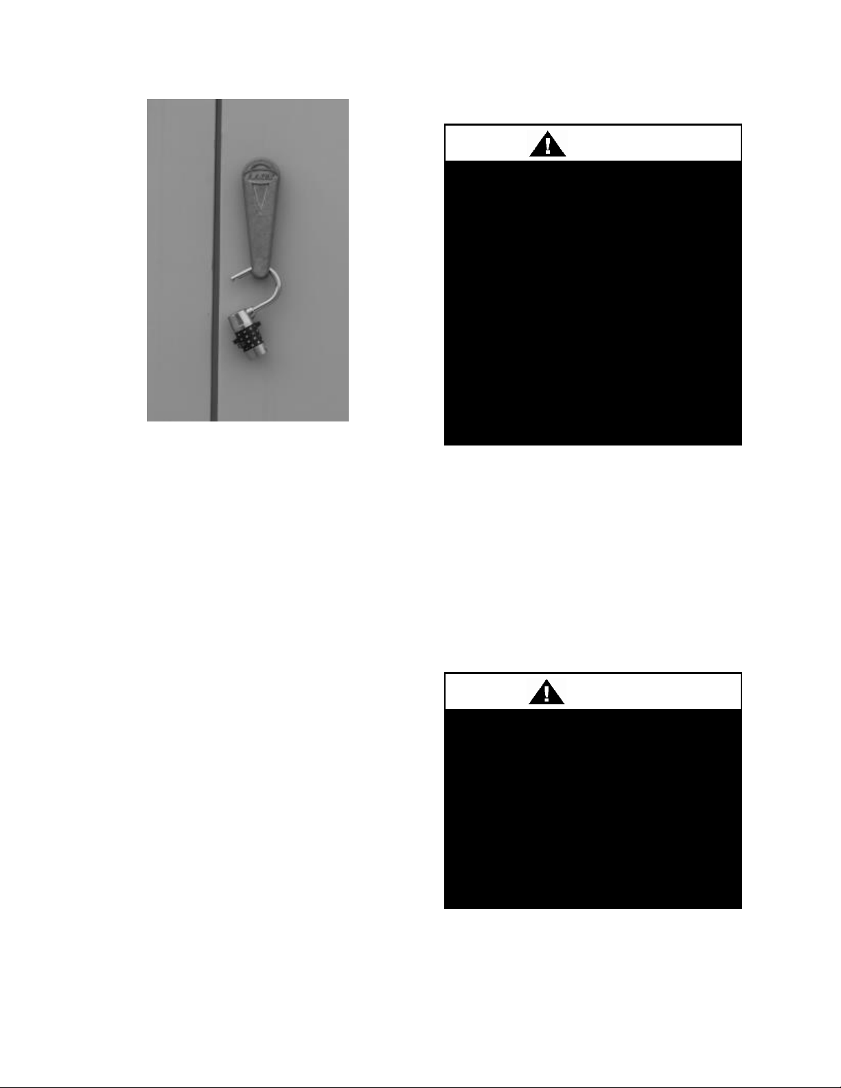
Door compartments containing
hazardous voltage or rotating parts
are equipped with door latches to
allow locks. Door latch are shipped
with nut and bolts requiring tooled
access. If you do not replace the
shipping hardware with a pad lock
always re-install the nut & bolt after
closing the door.
CAUTION
Cleaning the cooling tower or
condenser water loop with harsh
chemicals such as hydrochloric acid
(muriatic acid), chlorine or other
chlorides, can damage the
refrigerant-to-water heat exchanger.
Care should be taken to avoid
allowing chemicals to enter the
refrigerant-to-water heat exchanger.
See Appendix A - Heat Exchanger
Corrosion Resistance for more
information.
CAUTION
OPEN LOOP APPLICATIONS
Failure of the condenser as a result
of chemical corrosion is excluded
from coverage under AAON Inc.
warranties and the heat exchanger
manufacturer’s warranties.
WARNING
WARNING
COMPRESSOR CYCLING
5 MINUTE MINIMUM OFF TIME
To prevent motor overheating
compressors must cycle off for a
minimum of 5 minutes.
5 MINUTE MINIMUM ON TIME
To maintain the proper oil level
compressors must cycle on for a
minimum of 5 minutes.
The cycle rate must not exceed 6
starts per hour.
WARNING
WARNING
1. Startup and service must be performed
by a Factory Trained Service
Technician.
2. Use only with type of the gas approved
for the furnace. Refer to the furnace
rating plate.
3. The unit is for outdoor use only. See
General Information section for more
information.
11
Page 12

4. Provide adequate combustion ventilation
air to the furnace. If a vent duct
extension is used, a class III approved
vent is required. See the Locating Units
and Gas Heating sections of the
Installation section of the manual.
5. Always install and operate furnace
within the intended temperature rise
range and duct system external static
pressure (ESP) as specified on the unit
nameplate.
6. The supply and return air ducts must be
derived from the same space. It is
recommended ducts be provided with
access panels to allow inspection for
duct tightness. When a down flow duct
is used with electric heat, the exhaust
duct should be an L shaped duct.
7. Clean furnace, duct and components
upon completion of the construction
setup. Verify furnace operating
conditions including input rate,
temperature rise and ESP.
8. Every unit has a unique equipment
nameplate with electrical, operational,
and unit clearance specifications.
Always refer to the unit nameplate for
specific ratings unique to the model you
have purchased.
9. READ THE ENTIRE INSTALLATION,
OPERATION AND MAINTENANCE
MANUAL. OTHER IMPORTANT
SAFETY PRECAUTIONS ARE
PROVIDED THROUGHOUT THIS
MANUAL.
10. Keep this manual and all literature
safeguarded near or on the unit.
12
Page 13
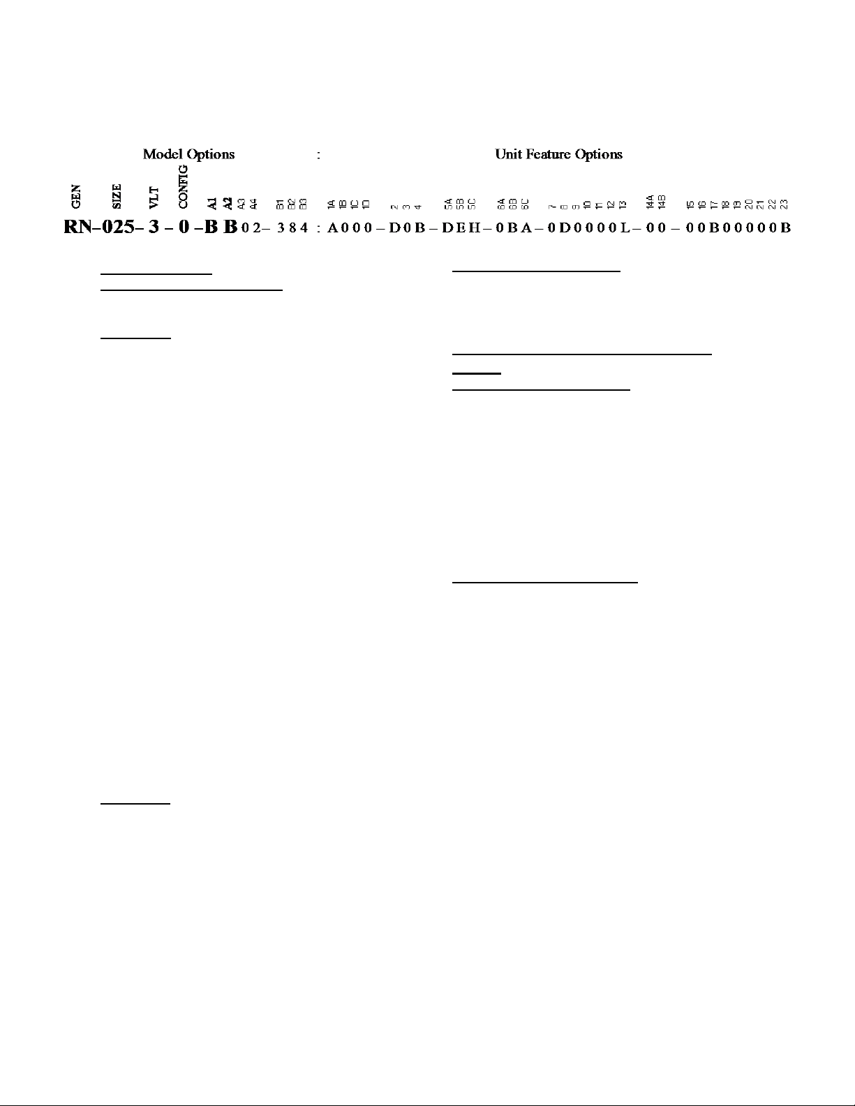
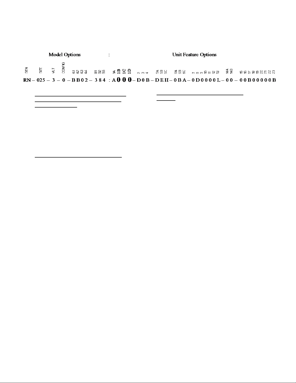
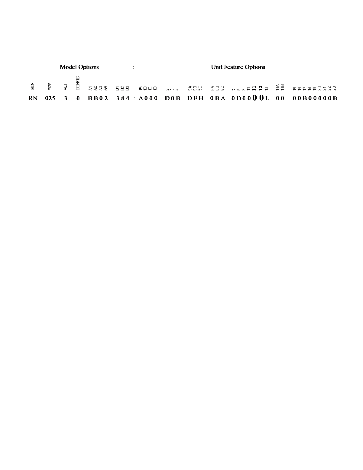
BASE MODEL
SERIES AND GENERATION
RN
UNIT SIZE
006 = 6 ton Capacity
007 = 7 ton Capacity
008 = 8 ton Capacity
009 = 9 ton Capacity
010 = 10 ton Capacity
011 = 11 ton Capacity
013 = 13 ton Capacity
015 = 15 ton Capacity
016 = 16 ton Capacity
018 = 18 ton Capacity
020 = 20 ton Capacity
025 = 25 ton Capacity
026 = 26 ton Capacity
030 = 30 ton Capacity
031 = 31 ton Capacity
040 = 40 ton Capacity
050 = 50 ton Capacity
055 = 55 ton Capacity
060 = 60 ton Capacity
065 = 65 ton Capacity
070 = 70 ton Capacity
075 = 75 ton Capacity
090 = 90 ton Capacity
105 = 105 ton Capacity
120 = 120 ton Capacity
130 = 130 ton Capacity
140 = 140 ton Capacity
VOLTAGE
1 = 230V/1Φ/60Hz
2 = 230V/3Φ/60Hz
3 = 460V/3Φ/60Hz
4 = 575V/3Φ/60Hz
8 = 208V/3Φ/60Hz
9 = 208V/1Φ/60Hz
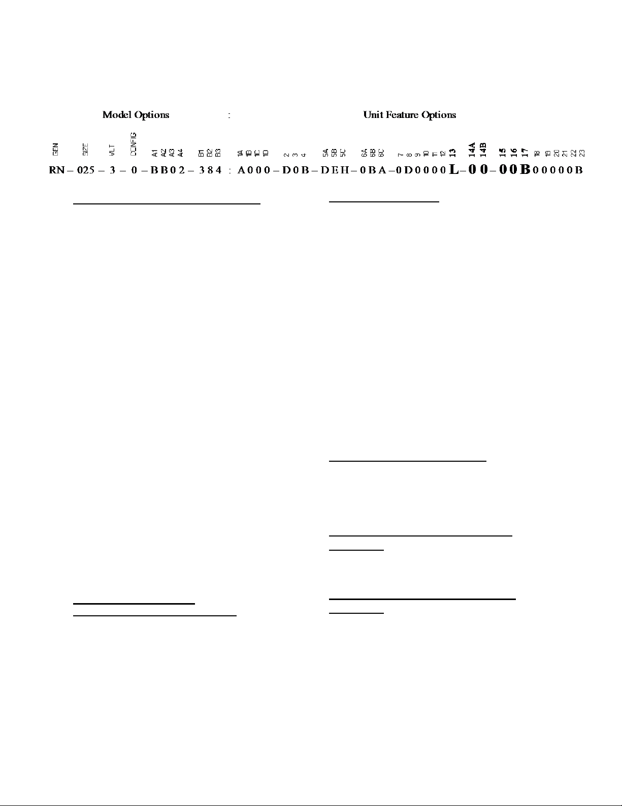
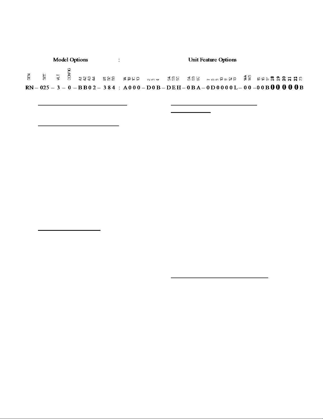
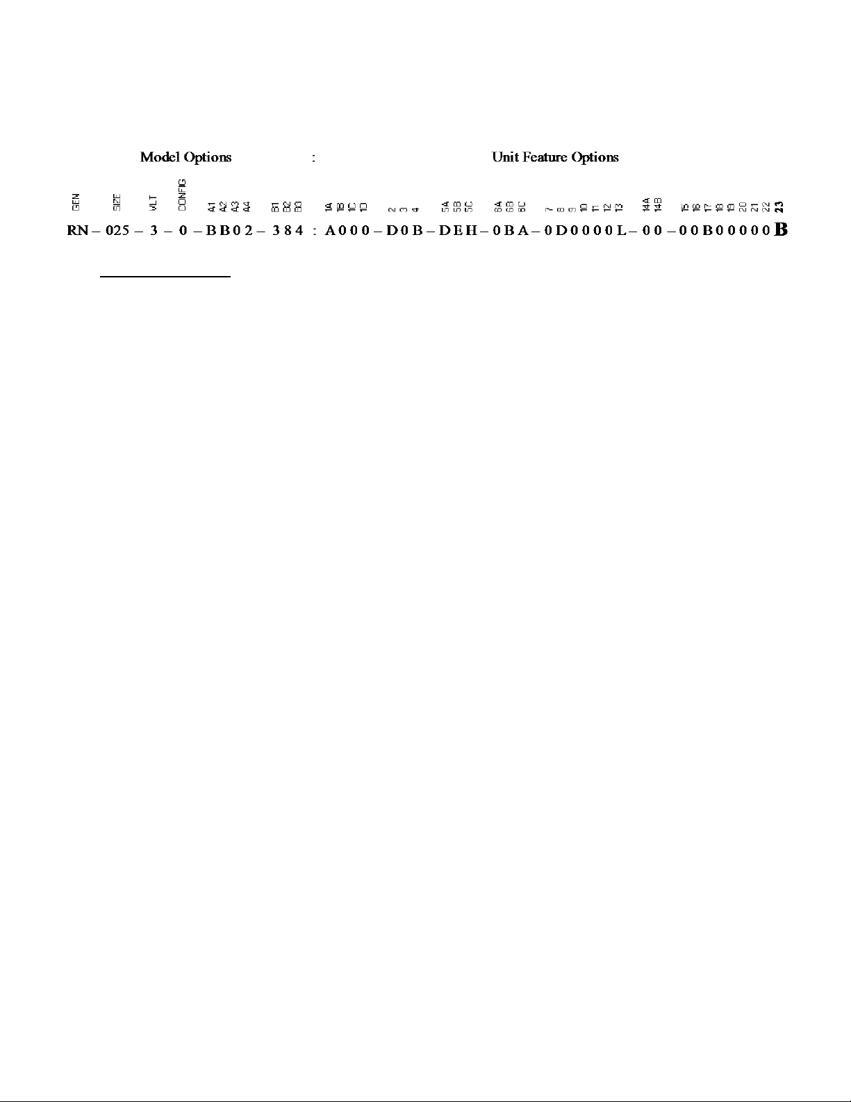
RN Series Feature String Nomenclature
INTERIOR PROTECTION
0 = Standard - Vertical Discharge and Return
A = Interior Corrosion Protection - Vertical
Discharge and Return
Model Option A: COOLING/HEAT
PUMP
A1: REFRIGERANT STYLE
0 = Air Handling Unit
B = R-410A - High Efficiency
C = R-410A - Standard Efficiency
E = R-410A Variable Capacity Scroll Compressor High Efficiency
F = R-410A Variable Capacity Scroll Compressor Standard Efficiency
J = R-410A VFD Compatible Scroll Compressor
K = R-410A VFD Compatible Scroll Compressor +
Microchannel Condenser
A2: UNIT CONFIGURATION
0 = No Cooling
A = Air-Cooled Cond. + Std Evap. Coil
B = Air-Cooled Cond. + 6 Row Evap. Coil
J = Water-Cooled Cond. + Std Evap. Coil
K = Water-Cooled Cond. + 6 Row Evap. Coil
P = Air-Cooled Cond. + 6 Row Evap. Coil + Mixed
Air Bypass
Q = Air-Cooled Cond. + 6 Row Evap. Coil + Return
Air Bypass
R = Water-Cooled Cond. + 6 Row Evap. Coil +
Return Air Bypass
T = Water-Cooled Cond. + 6 Row Evap. Coil +
Mixed Air Bypass
U = Chilled Water Coil - 4 Row
W = Chilled Water Coil - 6 Row
2 = Non-Compressorized + Std Evap. Coil
4 = Non-Compressorized + 6 Row Evap. Coil
6 = Air-Source Heat Pump
7 = Water-Source/Geothermal Heat Pump
13
Page 14
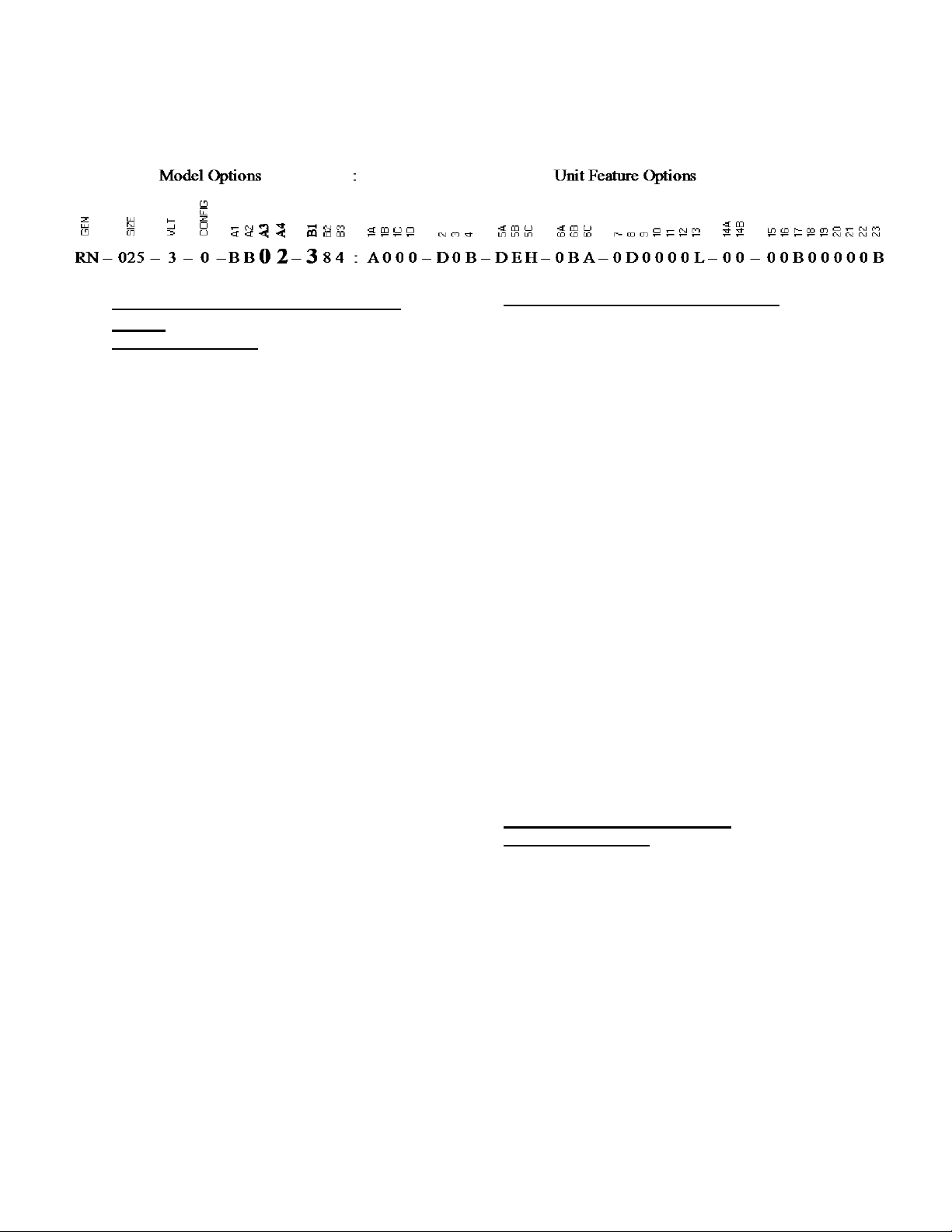
RN Series Feature String Nomenclature
Model Option A: COOLING/HEAT
PUMP
A3: COIL COATING
0 = Standard
1 = Polymer E-Coated Evap. and Cond.
2 = Stainless Steel Casing Evap and Cond
8 = Polymer E-Coated Cond.
9 = Polymer E-Coated Cooling Coil
A = Stainless Steel Evap. Coil Casing + Polymer ECoated Cond. Coil
B = Stainless Steel Casing Cond & Polymer ECoated Cooling Coil
C = Stainless Steel Casing Cond. Only
D = Stainless Steel Cooling Coil Casing
A4: COOLING/HEAT PUMP STAGING
0 = No Cooling
1 = 1 Stage
2 = 2 Stage
4 = 4 Stage
9 = Modulating - Lead VCC
A = Modulating - All VCC
B = 1 Stage + 1 Stage Auxiliary Heat
C = 2 Stage + 1 Stage Auxiliary Heat
D = 4 Stage + 1 Stage Auxiliary Heat
E = Modulating - Lead VCC + 1 Stage Aux. Heat
F = Modulating - All VCC + 1 Stage Aux. Heat
H = Single Serpentine 8 fpi
J = Half Serpentine 8 fpi
K = Single Serpentine 10 fpi
L = Half Serpentine 10 fpi
M = Single Serpentine 12 fpi
N = Half Serpentine 12 fpi
P = 1 Stage + 2 Stage Auxiliary Heat
Q = 2 Stage + 2 Stage Auxiliary Heat
R = 4 Stage + 2 Stage Auxiliary Heat
S = Modulating - Lead VCC + 2 Stage Aux. Heat
T = Modulating - All VCC + 2 Stage Aux. Heat
U = 1 Stage + 4 Stage Auxiliary Heat
V = 2 Stage + 4 Stage Auxiliary Heat
W = 4 Stage + 4 Stage Auxiliary Heat
Y = Modulating - Lead VCC + 4 Stage Aux. Heat
Z = Modulating - All VCC + 4 Stage Aux. Heat
Model Option B: HEATING
B1: HEATING TYPE
0 = No Heating
1 = Electric Heat
2 = Natural Gas Aluminized
3 = Natural Gas Stainless Steel
4 = High Altitude Natural Gas Aluminized
5 = High Altitude Natural Gas Stainless Steel
6 = LP Gas Aluminized
7 = LP Gas Stainless Steel
8 = High Altitude LP Gas Aluminized
9 = High Altitude LP Gas Stainless Steel
C = Steam Distributing Standard
D = Steam Distributing Polymer E-Coated
E = Hot Water Standard
F = Hot Water Polymer E-Coated
14
Page 15
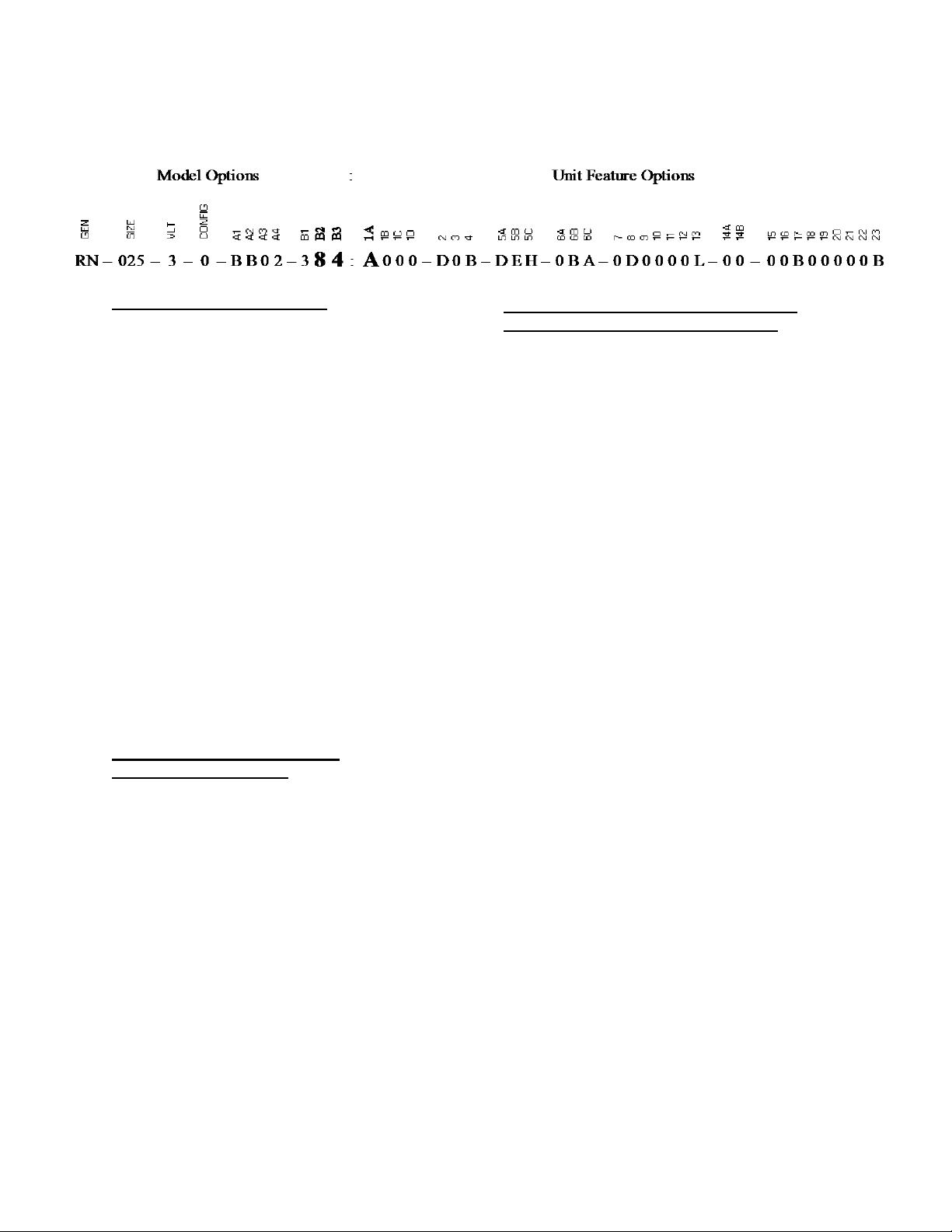
RN Series Feature String Nomenclature
B2: HEATING DESIGNATION
0 = No Heating
1 = Heat 1
2 = Heat 2
3 = Heat 3
4 = Heat 4
6 = Heat 6
7 = Heat 7
8 = Heat 8
9 = Heat 9
A = Heat A
B = Heat B
C = Heat C
D = Heat D
E = Heat E
F = Heat F
G = Heat G
H = 1 Row Coil
J = 2 Row Coil
K = Heat K
L = Heat L
M = Heat M
N = Heat N
P = Heat P
Model Option B: HEATING
B3: HEATING STAGING
0 = No Heating
1 = 1 Stage
2 = 2 Stage
3 = 3 Stage
4 = 4 Stage
5 = 5 Stage
6 = 6 Stage
7 = 7 Stage
8 = 8 Stage
9 = Modulating Gas/SCR Electric
A = Modulating/SCR Electric, 0-10V Control Signal
H = Single Serpentine 8 fpi
J = Half Serpentine 8 fpi
K = Single Serpentine 10 fpi
L = Half Serpentine 10 fpi
M = Single Serpentine 12 fpi
N = Half Serpentine 12 fpi
Feature 1: RETURN/OUTSIDE AIR
1A: RETURN/OUTSIDE AIR SECTION
0 = Manually Adjustable OA Opening + RA Opening
A = Economizer
B = Econ + Power Exhaust
C = Econ + Power Return
D = Econ + PE - Discharge Damper Volume Control
E = Econ + PE - Discharge Damper Volume Control
+ 0-10V External Control
F = Low cfm Total Energy Recovery Wheel
G = Low cfm Total ERW + Bypass
H = Low cfm Sensible ERW
J = Low cfm Sensible ERW + Bypass
K = 100% Outside Air - No Return Air
L = Motorized Outside Air Damper + RA Opening
M = Motorized Outside Air Damper - No Return Air
N = Empty ERW Option Box - No Power Exhaust
P = Empty ERW Option Box + Power Exhaust
Q = 1% Purge Low cfm Total ERW
R = 1% Purge Low cfm Total ERW + Bypass
S = 1% Purge Low cfm Sensible ERW
T = 1% Purge Low cfm Sensible ERW + Bypass
U = High cfm Total ERW
V = High cfm Total ERW + Bypass
W = High cfm Sensible ERW
Y = High cfm Sensible ERW + Bypass
Z = 1% Purge High cfm Total ERW
1 = 1% Purge High cfm Total ERW + Bypass
2 = 1% Purge High cfm Sensible ERW
3 = 1% Purge High cfm Sensible ERW + Bypass
4 = Single Total Energy Recovery Wheel + Bypass
5 = 100% Return Air
15
Page 16
RN Series Feature String Nomenclature
Feature 1: RETURN/OUTSIDE AIR
1B: RETURN/EXHAUST AIR BLOWER
CONFIGURATION
0 = Standard – None
A = 1 Blower + Standard Eff. Motor
C = 1 Blower + Premium Eff. Motor
D = 2 Blowers + Premium Eff. Motors
E = 1 Blower + Premium Eff. + 1 VFD
F = 2 Blowers + Premium Eff. + 1 VFD
G = 2 Blowers + Premium Eff. + 2 VFDs
1C: RETURN/EXHAUST AIR BLOWER
0 = Standard - None
A = 12”x9” Forward Curved
B = 15” Backward Curved Plenum
C = 18.5” Backward Curved Plenum
D = 22” Backward Curved Plenum
F = 27” Backward Curved Plenum
G = 22” Direct Drive Axial Flow
H = 35.5” Direct Drive Axial Flow
J = 15” BC Plenum - 50% Width with Banding
K = 18.5” BC Plenum - 70% Width with Banding
L = 22” BC Plenum - 70% Width with Banding
M = 27” BC Plenum - 70% Width with Banding
N = 30” Backward Curved Plenum
P = 42” 9 Blade Direct Drive Axial Flow
Q = 42” 12 Blade Direct Drive Axial Flow
R = 24” Backward Curved Plenum
S = 33” Backward Curved Plenum
1D: RETURN/EXHAUST AIR BLOWER
MOTOR
0 = Standard - None
C = 1 hp - 1760 rpm
D = 2 hp - 1760 rpm
E = 3 hp - 1760 rpm
F = 5 hp - 1760 rpm
G = 7.5 hp - 1760 rpm
H = 10 hp - 1760 rpm
L = 15 hp - 1760 rpm
M = 20 hp - 1760 rpm
N = 1 hp - 1170 rpm
P = 2 hp - 1170 rpm
Q = 3 hp - 1170 rpm
R = 5 hp - 1170 rpm
S = 7.5 hp - 1170 rpm
T = 10 hp - 1170 rpm
U = 15 hp - 1170 rpm
V = 20 hp - 1170 rpm
W = 25 hp - 1170 rpm
Y = 30 hp - 1170 rpm
3 = 25 hp - 1760 rpm
4 = 30 hp - 1760 rpm
5 = 40 hp - 1760 rpm
6 = 50 hp - 1760 rpm
16
Page 17
RN Series Feature String Nomenclature
Feature 2: OUTSIDE AIR CONTROL
0 = Standard - None
A = 3 Position Actuator - Sensible Limit
B = 3 Position Actuator - Enthalpy Limit
C = Fully Modulating Actuator - Sensible Limit
D = Fully Modulating Actuator - Enthalpy Limit
E = DDC Actuator
F = Constant Volume Outside Air
G = Options A + F
H = Options B + F
J = Options C + F
K = Options D + F
L = Options E + F
M = 3 Pos. Act. - Sensible Limit + CO2 Override
N = 3 Pos. Act. - Enthalpy Limit + CO2 Override
P = Fully Mod. Act. - Sensible + CO2 Override
Q = Fully Mod. Act. - Enthalpy + CO2 Override
R = DDC Actuator + CO2 Override
S = Dual Minimum Position Potentiometers + Fully
Mod. Act. - Sensible Limit
T = Dual Minimum Position Potentiometers + Fully
Mod. Act. - Enthalpy Limit
U = 2 Position Actuator
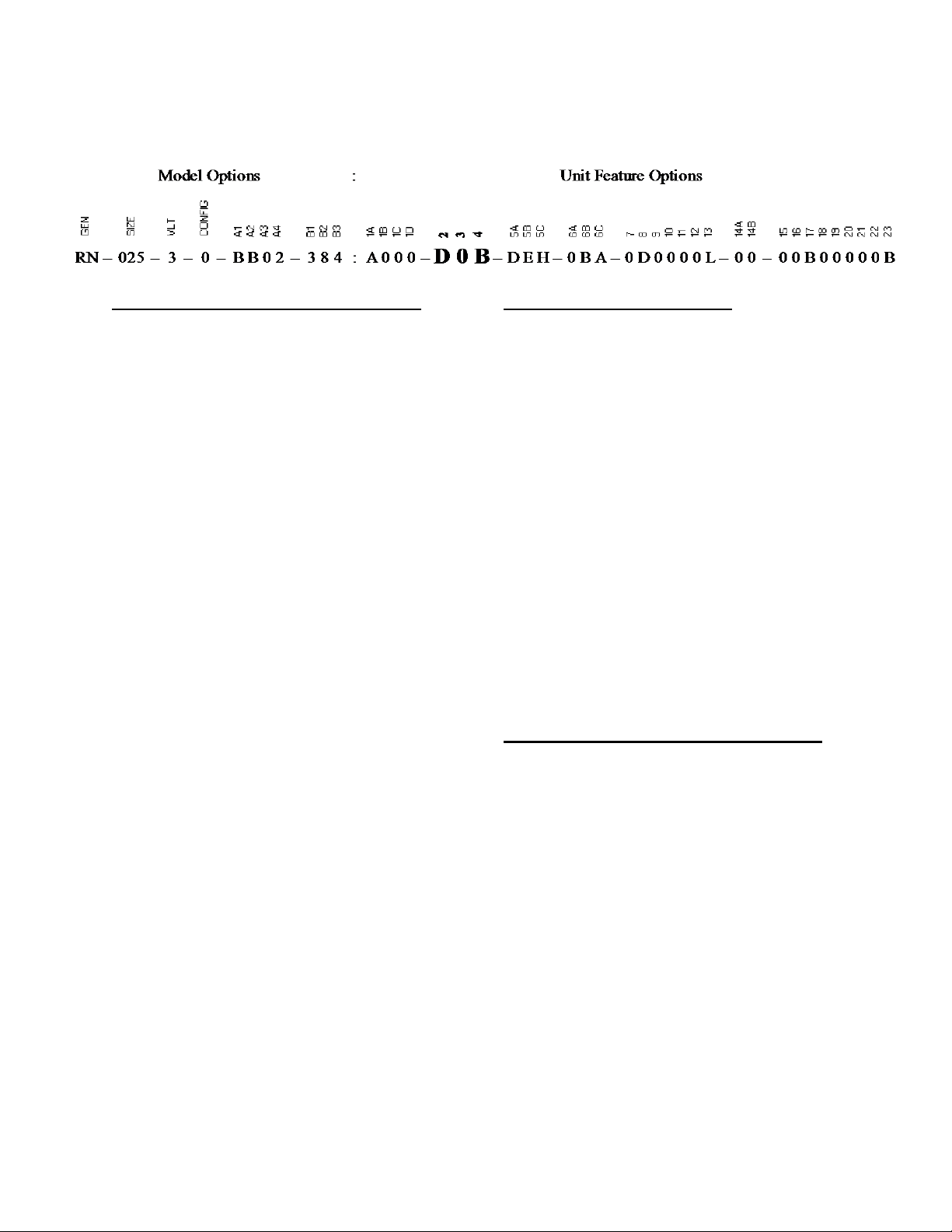
Feature 3: HEAT OPTIONS
0 = Standard - None
A = Regulator (2psi) with vent limiting device
B = Regulator (5psi) with vent limiting device
C = Regulator (2psi) vented
D = Regulator (5psi) vented
E = Discharge Air Override
F = Options A + E
G = Options B + E
H = Options C + E
J = Options D + E
K = Auxiliary Heat K
L = Auxiliary Heat L
M = Auxiliary Heat M
N = Auxiliary Heat N
P = Auxiliary Heat P
Q = Auxiliary Heat Q
R = Auxiliary Heat R
S = Auxiliary Heat S
T = Auxiliary Heat T
U = Auxiliary Heat U
V = Auxiliary Heat V
W = Auxiliary Heat W
Feature 4: MAINTENANCE OPTIONS
0 = Standard - None
A = Field Wired 115V Outlet
B = Factory Wired 115V Outlet
C = Blower Aux. Contact
D = Remote Start/Stop Terminals
E = Options A + C
F = Options A + D
G = Options B + C
H = Options B + D
J = Options A + C + D
K = Options B + C + D
L = Options C + D
17
Page 18
RN Series Feature String Nomenclature
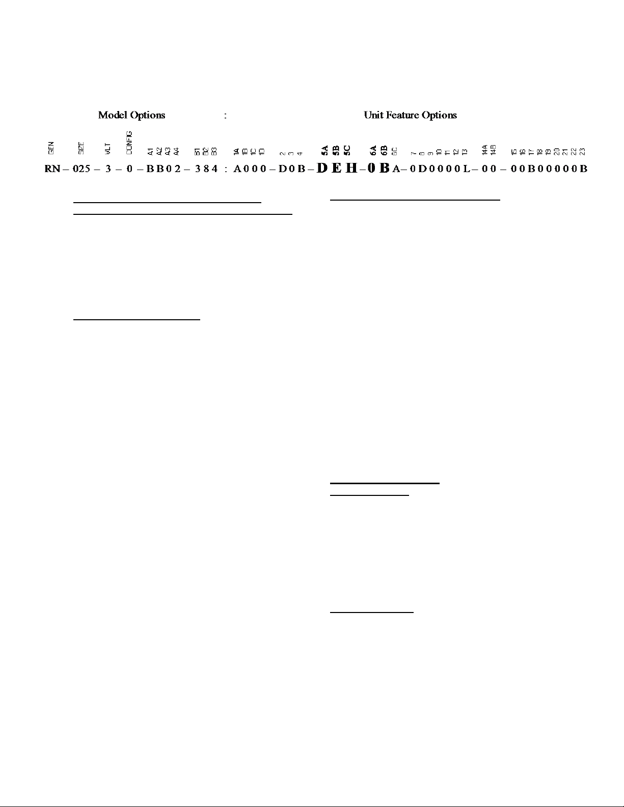
Feature 5: SUPPLY AIR OPTIONS
5A: SUPPLY AIR BLOWER CONFIGURATION
0 = 1 Blower + Standard Eff. Motor
A = 2 Blowers + Standard Eff. Motors
B = 1 Blower + Premium Eff. Motor
C = 2 Blowers + Premium Eff. Motors
D = 1 Blower + Premium Eff. + 1 VFD
F = 2 Blowers + Premium Eff. + 1 VFD
G = 2 Blowers + Premium Eff. + 2 VFDs
5B: SUPPLY AIR BLOWER
B = 15” Backward Curved Plenum
C = 18.5” Backward Curved Plenum
D = 24” Backward Curved Plenum
E = 27” Backward Curved Plenum
F = 30” BC Plenum - 90% Width + 1750 rpm Max -
Aluminum Wheel
G = 15” BC Plenum - 70% Width
H = 18.5” BC Plenum - 70% Width
J = 18.5” Backward Curved Plenum
K = 18.5” BC Plenum - 60% Width
L = 30” BC Plenum - 1600 rpm Max - Aluminum
Wheel
M = 13.5” Backward Curved Plenum
N = 13.5” BC Plenum - 70% Width
P = 24” BC Plenum - 60% Width
Q = 27” BC Plenum - 60% Width
R = 22” Backward Curved Plenum
S = 22” BC Plenum - 70% Width
T = 17” Backward Curved Plenum
U = 17” BC Plenum - 70% Width
V = 33” Backward Curved Plenum
W = 36.5” Backward Curved Plenum
Y = 42.5” Backward Curved Plenum
5C: SUPPLY AIR BLOWER MOTOR
C = 1 hp - 1760 rpm
D = 2 hp - 1760 rpm
E = 3 hp - 1760 rpm
F = 5 hp - 1760 rpm
G = 7.5 hp - 1760 rpm
H = 10 hp - 1760 rpm
L = 15 hp - 1760 rpm
M = 20 hp - 1760 rpm
N = 1 hp - 1170 rpm
P = 2 hp - 1170 rpm
Q = 3 hp - 1170 rpm
R = 5 hp - 1170 rpm
S = 7.5 hp - 1170 rpm
T = 10 hp - 1170 rpm
U = 15 hp - 1170 rpm
V = 20 hp - 1170 rpm
W = 25 hp - 1170 rpm
Y = 30 hp - 1170 rpm
3 = 25 hp - 1760 rpm
4 = 30 hp - 1760 rpm
5 = 40 hp - 1760 rpm
6 = 50 hp - 1760 rpm
Feature 6: FILTERS
6A: PRE FILTER
0 = Standard - None
A = 2” Pleated - 30% Eff. - MERV 8
B = Metal Mesh Outside Air Filter
C = Lint Screen Filter
D = Exhaust Air ERW Filter
F = Options A + D
G = Options B + D
H = Options A + B + D
6B: UNIT FILTER
0 = 2” Throwaway
or 2” Pleated - 30% Eff. - MERV 8
A = 2” Pleated - 30% Eff. - MERV 8
B = 4” Pleated - 30% Eff. - MERV 8
C = 2” Permanent Filter + Replaceable Media
F = 4” Pleated - 65% Eff. - MERV 11
G = 4” Pleated - 85% Eff. - MERV 13
H = 4” Pleated - 95% Eff. - MERV 14
18
Page 19
RN Series Feature String Nomenclature
6C: FILTER OPTIONS
0 = Standard
A = Clogged Filter Switch
B = Magnehelic Gauge
C = Options A + B
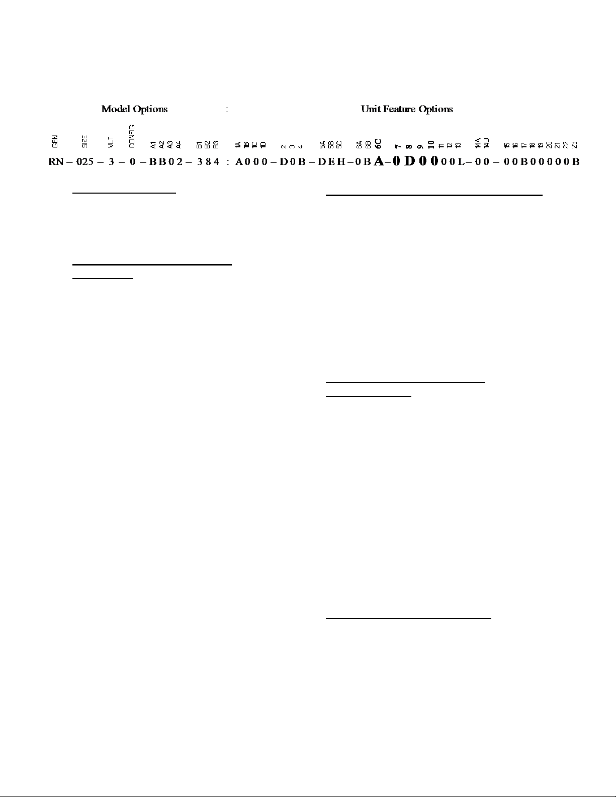
Feature 7: REFRIGERATION
CONTROL
0 = Standard
A = 5 Min. Time Delay Relay - Comp. Off
B = 20 Sec. Time Delay Relay - Comp. Staging
C = Fan Cycling
D = Adjustable Lockouts - Each Circuit
E = Freeze Stats - Each Circuit
F = Options A + B
G = Options A + C
H = Options A + D
J = Options A + E
K = Options B + C
L = Options B + D
M = Options B + E
N = Options C + D
P = Options C + E
Q = Options D + E
R = Options A + B + C
S = Options A + B + D
T = Options A + B + E
U = Options A + C + D
V = Options A + C + E
W = Options A + D + E
Y = Options B + C + D
Z = Options B + C + E
1 = Options B + D + E
2 = Options C + D + E
3 = Options A + B + C + D
4 = Options A + B + C + E
5 = Options A + B + D + E
6 = Options A + C + D + E
7 = Options B + C + D + E
8 = Options A + B + C + D + E
Feature 8: REFRIGERATION OPTIONS
0 = Standard
A = Hot Gas Bypass Lead Stage
or Hot Gas Bypass Lag Stage with Lead Variable
Capacity Compressor
B = Hot Gas Bypass Lead and Lag Stages
C = Hot Gas Reheat
D = Modulating Hot Gas Reheat
E = 0°F Low Ambient Lead Stage
F = Options A + C
G = Options B + C
H = Options A + D
J = Options B + D
K = Options A + E
L = Options B + E
Feature 9: REFRIGERATION
ACCESSORIES
0 = Standard
A = Sight Glass
B = Compressor Isolation Valves
C = Options A + B
D = ECM Condenser Fan - Multiple Speed
E = ECM Condenser Fan - Head Pressure Control
F = VFD Controlled Condenser Fans - Variable
Speed
G = Options A + D
H = Options B + D
J = Options A + B + D
K = Options A + E
L = Options B + E
M = Options A + B + E
N = Options A + F
P = Options B + F
Q = Options C + F
Feature 10: POWER OPTIONS
0 = Standard Power Block
A = 100 Amp Power Switch
B = 150 Amp Power Switch
C = 225 Amp Power Switch
D = 400 Amp Power Switch
E = 600 Amp Power Switch
F = 60 Amp Power Switch
5 = 800 Amp Power Switch
6 = 1200 Amp Power Switch
19
Page 20
Feature 11: SAFETY OPTIONS
0 = Standard
A = Return and Supply Air Firestat
B = Return Air Smoke Detector
C = Supply Air Smoke Detector
D = Options B + C
E = Options A + B
F = Options A + C
G = Options A + B + C
H = Remote Smoke Detector Terminals
J = Options A + H
K = Options B + H
L = Options C + H
M = Options D + H
N = Options A + B + H
P = Options A + C + H
Q = Options A + B + C + H
RN Series Feature String Nomenclature
Feature 12: CONTROLS
0 = Standard
A = Low Limit Controls
B = Phase and Brown Out Protection
C = Energy Recovery Wheel Defrost
D = Energy Recovery Wheel Rotation Detection
E = Compressor Power Factor Correction
F = Options A + B
G = Options A + C
H = Options A + D
J = Options A + E
K = Options B + C
L = Options B + D
M = Options B + E
N = Options C + D
P = Options C + E
Q = Options D + E
R = Options A + B + C
S = Options A + B + D
T = Options A + B + E
U = Options A + C + D
V = Options A + C + E
W = Options A + D + E
Y = Options B + C + D
Z = Options B + C + E
1 = Options B + D + E
2 = Options C + D + E
3 = Options A + B + C + D
4 = Options A + B + C + E
5 = Options A + B + D + E
6 = Options A + C + D + E
7 = Options B + C + D + E
8 = Options A + B + C + D + E
20
Page 21
RN Series Feature String Nomenclature
Feature 13: SPECIAL CONTROLS
0 = Terminal Block for Thermostat Control
D = VAV Unit Controller - VAV Cool + CV Heat
E = Constant Volume Unit Controller - CV Cool +
CV Heat
F = Makeup Air Unit Controller - CV Cool + CV
Heat
H = Field Installed DDC Controls by Others
J = Factory Installed DDC Controls Furnished by
Others
K = Factory Installed DDC Controls Furnished by
Others w/ Isolation relays
L = Terminal Block for Thermostat Control with
Isolation Relays
U = Digital Precise Air Controller, D-PAC
V = Precise Air Controller, PAC
W = Terminal Block for Variable Capacity
Compressor Thermostat
Y = VAV Single Zone Heat Pump Unit Controller VAV Cool + VAV Heat
Z = Constant Volume Heat Pump Unit Controller CV Cool + CV Heat
1 = Makeup Air Heat Pump Unit Controller - CV
Cool + CV Heat
2 = VAV Single Zone Unit Controller VAV Cool +
CV Heat
3 = VAV Single Zone Unit Controller VAV Cool +
VAV Heat
4 = Field Installed DDC Controls by Others
5 = Field Installed DDC Controls Furnished by
Others with Isolation Relays
6 = Factory Installed DDC Controls Furnished by
Others with Isolation Relays (SPA)
Feature 14: PREHEAT
14A: PREHEAT CONFIGURATION
0 = Standard - None
A = Steam Distributing Preheat Coil - 1 Row
B = Steam Distributing Preheat Coil - 2 Row
C = Hot Water Preheat Coil - 1 Row
D = Hot Water Preheat Coil - 2 Row
E = Modulating Electric Preheat
14B: PREHEAT SIZING
0 = Standard - None
A = Single Serpentine 8 fpi
B = Half Serpentine 8 fpi
C = Single Serpentine 10 fpi
D = Half Serpentine 10 fpi
E = Single Serpentine 12 fpi
F = Half Serpentine 12 fpi
G = 10 kW (7.5 kW @ 208V)
H = 15 kW (11.3 kW @ 208V)
J = 20kW (15 kW @ 208V)
K = 30kW (22.5 kW @ 208V)
L = 40kW (30 kW @ 208V)
M = 50kW (37.6 kW @ 208V)
N = 60kW (45.1 kW @ 208V)
P = 70kW (52.6 kW @ 208V)
Q = 80kW (60.1 kW @ 208V)
R = 90kW (67.6 kW @ 208V)
S = 100kW (75.1 kW @ 208V)
T = 110kW (82.6 kW @ 208V)
U = 120kW (90.1 kW @ 208V)
Feature 15: Glycol Percentage
0 = Standard
A = 20% Propylene Glycol
B = 40% Propylene Glycol
C = Field Adjustable for Glycol %
Feature 16: INTERIOR CABINET
OPTIONS
0 = Standard
B = Service Lights
Feature 17: EXTERIOR CABINET
OPTIONS
0 = Standard
A = Base Insulation
B = Burglar Bars
C = Condenser Coil Guards
D = Options A + B
E = Options A + C
F = Options B + C
G = Options A + B + C
21
Page 22
RN Series Feature String Nomenclature
Feature 18: CUSTOMER CODE
0 = Standard
Feature 19: CODE OPTIONS
0 = Standard - ETL U.S.A. Listing
B = Chicago - Cool + Gas
C = Chicago - Cool + Electric Heat
D = Chicago - Cool Only
E = Chicago - Gas Only
F = Chicago - Electric Heat Only
G = Chicago - No Cool + No Heat
H = ETL U.S.A. + Canada Listing
K = California OSHPD Certification
L = Shake Table Cert. (ASCE 7-05/ICC-ES AC 156)
M = Seismic Construction (Non-Certified)
N = California OSHPD Certification + Chicago
P = Shake Table Cert. (ASCE 7-05/ICC-ES AC 156)
+ Chicago
Q = Seismic Construction (Non-Certified) + Chicago
Feature 20: CRATING
0 = Standard
A = Export Crating
B = Export Crating - No Condenser Section
Feature 21: WATER-COOLED
CONDENSER
0 = Standard - None
A = Balancing Valves
B = Water Flow Switch
C = Motorized Shut-off Valve
D = Head Pressure Control
E = Options A + B
F = Options A + C
G = Options A + D
H = Options B + C
J = Options B + D
L = Options A + B + C
M = Options A + B + D
R = SMO 254 Brazed Plate Heat Exchanger
S = Options A + R
T = Options B + R
U = Options C + R
V = Options D + R
W = Options A + B + R
Y = Options A + C + R
Z = Options A + D + R
1 = Options B + C + R
2 = Options B + D + R
3 = Options C + D + R
4 = Options A + B + C + R
5 = Options A + B + D + R
Feature 22: CONTROL VENDORS
0 = None
A = WattMaster Orion Controls System
B = JENEsys Control System with Web UI
C = WattMaster Orion Controls System with Specials
E = Remote Mounted AAON Mini Controller
F = JENEsys Control System with Web UI + Fox
G = JENEsys Control System with Web UI + Lon
H = JENEsys Control w/ Web UI + BACnet MSTP
J = JENEsys Control w/ Web UI + BACnet IP
K = JENEsys Control w/ Web UI + Modbus RTU
L = JENEsys Control w/ Web UI + Modbus TCP
22
Page 23
RN Series Feature String Nomenclature
Feature 23: TYPE
B = Standard - AAON Gray Paint
U = Special Pricing Authorization + Special Paint
X = Special Pricing Authorization + AAON Gray
Paint
1 = Standard Paint + 2 Year Parts Only Warranty
4 = Standard Paint + 5 Year Parts Only Warranty
9 = Standard Paint + 10 Year Parts Only Warranty
23
Page 24
Improper installation, adjustment,
alteration, service, or maintenance
can cause property damage,
personal injury or loss of life. Startup
and service must be performed by a
Factory Trained Service Technician.
A copy of this IOM should be kept
with the unit.
WARNING
These units must not be used for
heating or cooling at any time during
any phase of construction. Very low
return air temperatures, harmful
vapors, and misplacement of the
filters will damage the unit and its
efficiency.
CAUTION
General Information
RN Series packaged rooftop units, heat
pumps and outdoor air handling units have
been designed for outdoor installation only.
Units are assembled, wired, charged and run
tested at the factory.
Startup and service must be performed by a
Factory Trained Service Technician.
Certification of Gas Heat Models
a. AAON gas heat exchangers have
successfully completed 10,000 burner
operation cycles and corrosion resistance
as specified per test standard ANSI
21.47. All gas heat exchangers used in
AAON appliances are certified for use
downstream of evaporator or cooling
coils.
b. Certified as a Category III forced air
furnace with or without cooling.
24
c. Certified for outdoor installation only.
d. Certified for installation on a
combustible roof with a minimum of 12”
high curb.
Certification of Steam or Hot Water Heat
Models
a. Certified as a forced air heating system
with or without cooling.
b. Certified for outdoor installation only.
c. Certified for installation on a
combustible roof with a minimum of 12”
high curb.
Certification of Electric Heat Models
a. Certified as an electric warm air furnace
with or without cooling.
b. Certified for outdoor installation only.
c. Certified for installation on a
combustible roof with a minimum of 12”
high curb.
Certification of Cooling Models
a. Certified as a commercial central air
conditioner with or without electrically
operated compressors.
b. Certified for outdoor installation only.
c. Certified for installation on a
combustible roof with a minimum of 12”
high curb.
d. Certified with refrigerant R-410A coils
or with chilled water cooling coils.
Codes and Ordinances
RN Series units have been tested and
certified, by ETL, in accordance with UL
Safety Standard 1995/CSA C22.2 No. 236,
ANSI Safety Standard Z21.47b-2008/CSA
2.3b-2008, and ANSI Safety Standard
Z83.8-2006/CSA 2.6-2006.
System should be sized in accordance with
the American Society of Heating,
Refrigeration and Air Conditioning
Engineers Handbook.
Page 25
The Clean Air Act of 1990 bans the
intentional venting of refrigerant as of
July 1, 1992. Approved methods of
recovery, recycling, or reclaiming
must be followed.
CAUTION
Coils and sheet metal surfaces
present sharp edges and care must
be taken when working with
equipment.
WARNING
Failure to observe the following
instructions will result in premature
failure of your system and possible
voiding of the warranty.
WARNING
Installation of RN Series units must conform
to the ICC standards of the International
Mechanical Code, the International Building
Code, and local building, plumbing and
waste water codes. In the absence of local
codes installation must conform to the
current (United States) National Fuel Gas
Code ANSI-Z223.1/NFPA 54 or the current
(Canada) National Fuel & Propane
Installation Code CSA B149.1 or B149.2,
and Mechanical Refrigeration Code CSA
B52. All appliances must be electrically
grounded in accordance with local codes, or
in the absence of local codes, the current
National Electric Code, ANSI/NFPA 70 or
the current Canadian Electrical Code CSA
C22.1.
Receiving Unit
When received, the unit should be checked
for damage that might have occurred in
transit. If damage is found it should be noted
on the carrier’s freight bill. A request for
inspection by carrier’s agent should be made
in writing at once. Nameplate should be
checked to ensure the correct model sizes
and voltages have been received to match
the job requirements.
If repairs must be made to damaged goods,
then the factory should be notified before
any repair action is taken in order to protect
the warranty. Certain equipment alteration,
repair, and manipulation of equipment
without the manufacturer’s consent may
void the product warranty. Contact the
AAON Warranty Department for assistance
with handling damaged goods, repairs, and
freight claims: (918) 583-2266.
Note: Upon receipt check shipment for
items that ship loose such as filters and
remote sensors. Consult order and shipment
documentation to identify potential looseshipped items. Loose-shipped items may
have been placed inside unit cabinet for
security. Installers and owners should secure
all doors with locks or nuts and bolts to
prevent unauthorized access.
25
Page 26
CRANKCASE HEATER
OPERATION
Some units are equipped with
compressor crankcase heaters,
which should be energized at least
24 hours prior to cooling operation, to
clear any liquid refrigerant from the
compressors.
CAUTION
COMPRESSOR CYCLING
5 MINUTE MINIMUM OFF TIME
To prevent motor overheating
compressors must cycle off for a
minimum of 5 minutes.
5 MINUTE MINIMUM ON TIME
To maintain the proper oil level
compressors must cycle on for a
minimum of 5 minutes.
The cycle rate must not exceed 6
starts per hour.
WARNING
Figure 1 - Lockable Handle
The warranty card must be completed in full
and returned to AAON not more than 3
months after unit is delivered.
Storage
If installation will not occur immediately
following delivery, store equipment in a dry
protected area away from construction
traffic and in the proper orientation as
marked on the packaging with all internal
packaging in place. Secure all loose-shipped
items.
26
Packaged Direct Expansion (DX) Units
All DX refrigeration systems are factory
assembled, leak tested, charged with
refrigerant, and run tested.
All refrigerant systems include an
evaporator, condenser, liquid line filter
driers, thermal expansion valves (TXV) and
scroll compressors. Compressors are
equipped with a positive pressure forced
lubrication system.
Page 27
Polyolester (POE) and Polyvinylether
(PVE) oils are two types of lubricants
used in hydrofluorocarbon (HFC)
refrigeration systems. Refer to the
compressor label for the proper
compressor lubricant type.
Never cut off the main power supply to the
unit, except for servicing, emergency, or
complete shutdown of the unit. When power
is cut off from the unit crankcase heaters
cannot prevent refrigerant migration into the
compressors. This means the compressor
will cool down and liquid refrigerant may
accumulate in the compressor. The
compressor is designed to pump refrigerant
gas and damage may occur when power is
restored.
If power to the unit must be off for more
than an hour, turn the thermostat system
switch to "OFF", or turn the unit off at the
control panel, and leave the unit off until the
main power switch has been turned on again
for at least 24 hours for units with
compressor crankcase heaters. This will give
the crankcase heater time to clear any liquid
accumulation out of the compressor before it
is started.
Always control the unit from the thermostat,
or control panel, never at the main power
supply, except for servicing, emergency or
complete shutdown of the unit.
During the cooling season, if the air flow is
reduced due to dirty air filters or any other
reason, the cooling coils can get too cold
which will cause excessive liquid to return
to the compressor. As the liquid
concentration builds up, oil is washed out of
the compressor, leaving it starved for
lubrication.
The compressor life will be seriously
shorted by reduced lubrication and the
pumping of excessive amounts of liquid oil
and refrigerant.
Note: Low Ambient Operation
Air-cooled DX units without a low ambient
option, such as condenser fan cycling or the
0°F low ambient option, will not operate in
the cooling mode of operation properly
when the outdoor temperature is below
55°F. Low ambient and/or economizer
options are recommended if cooling
operation below 55°F is expected.
Note: Multiple Units with Multiple
Thermostats
When several heating and cooling units are
used to condition a space all unit thermostat
switches must be set in either heating mode,
cooling mode or off. Do not leave part of the
units switched to the opposite mode.
Cooling only units should be switched off at
the thermostat during the heating season.
Gas or Electric Heating
The unit is designed to heat a given amount
of air while operating. If this amount of air
is greatly reduced, approximately 1/3 during
the heating season, the gas heat exchanger or
electric heating coil may overheat, and may
cut the burner or heater off entirely by action
of the safety high temperature limit devices
which are factory mounted at the heat
exchanger and supply fan areas.
Airflow should be adjusted after installation
to obtain an air temperature rise within the
range specified on the unit rating plate at the
required external static pressure.
27
Page 28
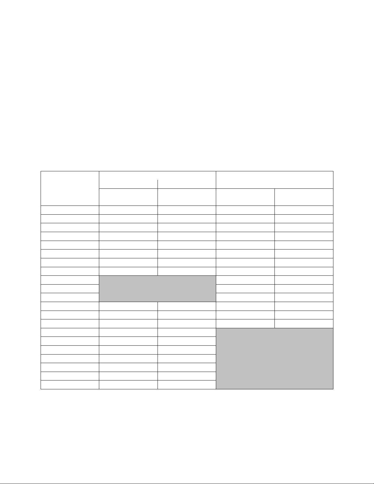
Model Option B2
Gas Heat
Electric Heat
Input Capacity
Output Capacity
Capacity
MBH
MBH
kW (208V)
kW (230V,
460V, 575V)
1 = Heat 1
60.0
48.0
7.5
10
2 = Heat 2
90.0
72.0
15.0
20
3 = Heat 3
100.0
80.0
22.5
30
4 = Heat 4
270.0
218.7
30.0
40
5 = Heat 5
140.0
112.0
37.5
50
6 = Heat 6
390.0
315.9
45.1
60
7 = Heat 7
160.0
128.0
60.1
80
8 = Heat 8
405.0
328.1
75.1
100
9 = Heat 9
90.1
120
A = Heat A
120.1
160
B = Heat B
150.2
200
C = Heat C
540.0
432.0
180.2
240
D = Heat D
810.0
648.0
210.3
280
E = Heat E
1080.0
864.0
240.3
320
F = Heat F
195.0
156.0
G = Heat G
292.5
234.0
K = Heat K
150.0
120.0
L = Heat L
210.0
168.0
M = Heat M
800.0
640.0
N = Heat N
1600.0
1280.0
P = Heat P
2400.0
1920.0
Should overheating occur with a gas heat
exchanger, or the gas supply fail to shut off,
shut off the manual gas valve to the furnace
before shutting off the electrical supply.
Prolonged overheating of the heat exchanger
will shorten its life.
If unit has not been selected as a 100%
outside air unit (makeup air unit) the return
air duct must be sealed to the unit and the
return air temperature must be maintained
between 55F and 80F.
Table 1 - Electric and Gas Heating Capacities
28
Page 29

Unit should not be operated without a
p-trap. Failure to install a p-trap may
result in overflow of condensate
water.
CAUTION
Wiring Diagrams
Unit specific wiring diagrams are laminated
and affixed inside the controls compartment
door.
Condensate Drain Pan
Unit requires drain traps to be connected to
the condensate drain pan of the unit. The 625 and 30 ton units include one drain pan
connection and the 26 and 31-140 ton units
include two drain pan connections.
Condensate drain pipes or p-traps for each
connection are factory supplied and shipped
loose in the controls compartment for field
installation.
If codes require a condensate drain line, the
line should be the same pipe size or larger
than the drain connection, include a p-trap,
and pitch downward toward drain. An air
break should be used with long runs of
condensate lines.
29
Page 30
Location
Unit Size
6-8 and 10 tons
Front -
(Controls Side)
48”
Back - (Outside Air)
36”
*Left Side
*6”
Right Side
48”
Top
Unobstructed
*Units with a water-cooled condenser or
chilled water coil require 48” of clearance
on the left side for service access. DX and
no cooling air handling units with an energy
recovery wheel require 24” of clearance on
the left side for service access.
Location
Unit Size
9 and 11-15 tons
Front -
(Controls Side)
48”
Back - (Outside Air)
48”
*Left Side
*6”
Right Side
48”
Top
Unobstructed
*Units with a water-cooled condenser or
chilled water coil require 48” of clearance
on the left side for service access. DX and
no cooling air handling units with an energy
recovery wheel require 24” of clearance on
the left side for service access.
When locating gas fired units, it is
recommended the unit be installed so
that the flue discharge vents are
located at least 120 inches away
from any opening through which
combustion products could enter the
building.
WARNING
Distances from adjacent public
walkways, adjacent buildings,
operable windows and building
openings, shall conform to local
codes and/or the National Fuel Gas
Code, ANSI Z223.1/NFPA 54, or the
National Gas & Propane Code, CSA
B149.1
WARNING
Installation
AAON equipment has been designed for
quick and easy installation.
Locating Units
The curb should be mounted first and must
be located so that duct connections will be
clear of structural members of the building.
Verify rooftop or foundation can support the
total unit weight, including accessory
weights.
Do not position flue opening to discharge
into a fresh air intake of any other piece of
equipment. Unit should also be installed so
that the flow of combustion intake air is not
obstructed from reaching the furnace.
Vent opening must not be blocked by snow.
A minimum 12” curb must be used or the
30
vent outlet shall be greater than 12” off the
ground/roof.
Flue gas is dangerously hot and contains
containments. The user is responsible for
determining if vent gases may degrade
building materials.
The National Gas and Propane Installation
Code, B149.1 specifies a 6 ft. horizontal
vent terminal clearance to gas and electric
meters and relief devices.
Local codes may supersede or further place
restrictions on vent termination locations.
Table 2 - A Cabinet Unit Clearances
Table 3 - B Cabinet Unit Clearances
Page 31
Location
Unit Size
16-25 and 30 tons
Front -
(Controls Side)
48”
Back - (Outside Air)
48”
*Left Side
*21”
Right Side
60”
Top
Unobstructed
*Units with a water-cooled condenser or
chilled water coil require 48” of clearance
on the left side for service access.
Location
Unit Size
26 and 31-70 tons
Front -
(Controls Side)
48”
Back - (Outside Air)
48”
*Left Side
*48”
*Right Side
*70”
Top
Unobstructed
*Right and left side unit clearances are
interchangeable on units that do not have
hydronic heating. Units with hydronic
heating require 70” right side access for
service.
Location
Unit Size
55, 65 and 75-140
tons
Front -
(Controls Side)
60”
Back - (Outside Air)
48”
Left Side
72”
Right Side
72”
Top
Unobstructed
Back
Right Side
Front
Front
Right Side
Back
Back
Front
Right Side
Table 4 - C Cabinet Unit Clearances
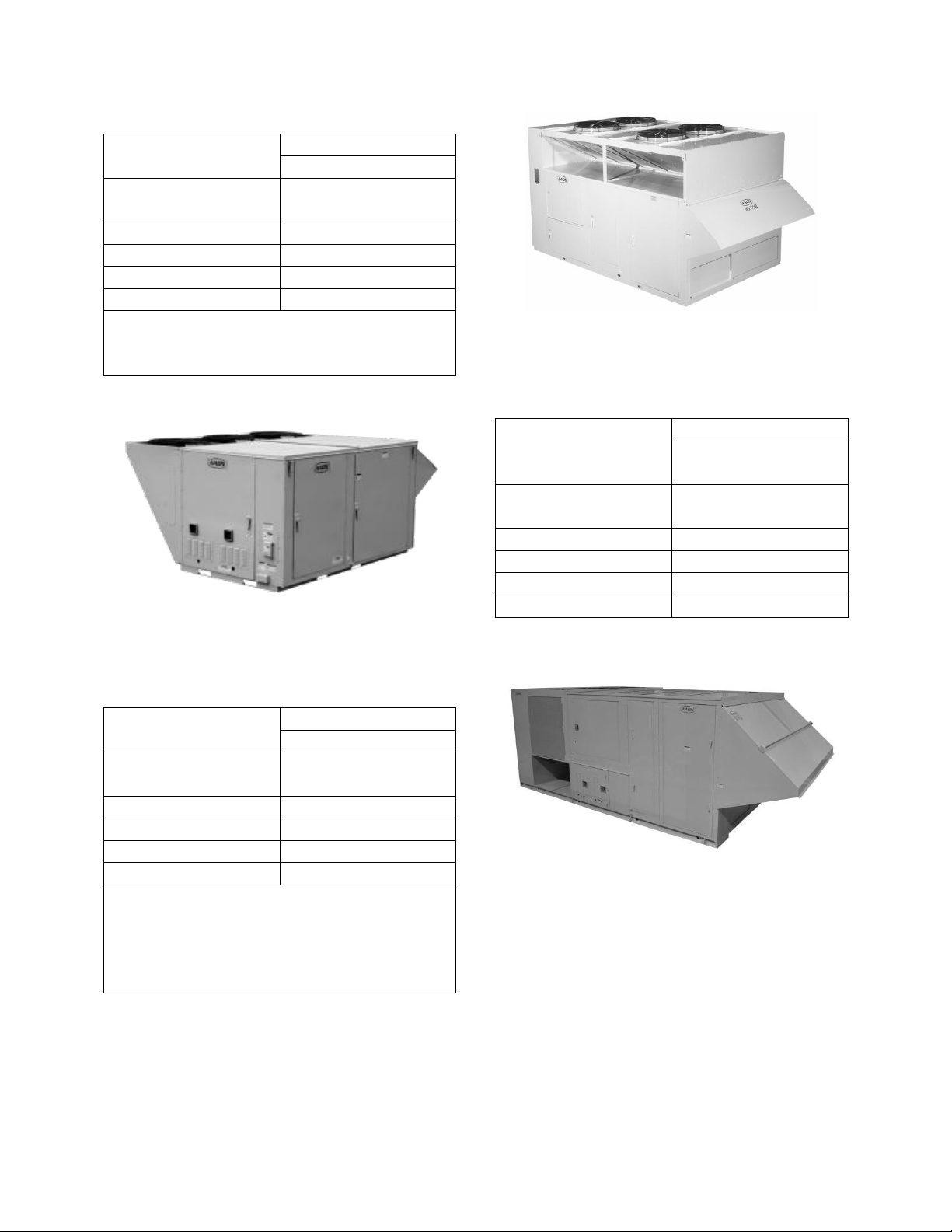
Figure 3 - RN Series D Cabinet,
26, 31-50, 60 and 70 tons
Table 6 - E Cabinet Unit Clearances
Figure 2 - RN Series A, B and C Cabinet,
6-25 and 30 tons
Table 5 - D Cabinet Unit Clearances
Figure 4 - RN Series E Cabinet,
55, 65 and 75-140 tons
Setting the Curb
Make openings in roof decking large enough
to allow for duct penetration and workspace
only. Do not make openings larger than
necessary. Set the curb to coincide with the
openings. Make sure the curb is level. Unit
must be level in both horizontal axes to
support the unit and reduce noise and
vibration.
31
Page 32

All roofing work should be performed
by competent roofing contractors to
avoid any possible leakage.
CAUTION
Where the supply or warm air duct
passes through a combustible roof, a
clearance of 1 inch must be
maintained between the outside
edges of the duct and combustible
material in accordance with National
Fire Protection Association Standard
No. 90A. Provide flashings or
enclosure between structure and roof
and all joints must be sealed with
mastic roofing to ensure a watertight
seal.
CAUTION
Be careful to install the provided neoprene
gasket according to the following figure
prior to setting the unit on the curb.
32
Page 33

Figure 5 - RN Series 6-8 and 10 ton Unit Gasket Locations
33
Page 34

34
Figure 6 - RN Series 9 and 11-15 ton Unit Gasket Locations
Page 35

Figure 7 - RN Series 16-25 and 30 ton Unit Gasket Locations
35
Page 36

36
Figure 8 - RN Series 26, 31-50, 60, and 70 ton Unit Gasket Locations
Page 37

Incorrect lifting can cause damage to
the unit.
CAUTION
Forks
FORKLIFTING
9, 11-25 AND 30 TON UNITS
Forks or Fork Extensions must be 72”
in length.
CAUTION
FORKLIFTING
6-8 AND 10 TON UNITS
Forks or Fork Extensions must be at
least 48” in length.
CAUTION
Forklifting the Unit (6-25 and 30 ton)
6-25 and 30 ton units can be lifted using a
forklift. 9, 11-25 and 30 ton units must have
forks 72” in length or the forks must have
72” fork extensions. 6-8 and 10 ton units
must have forks at least 48” in length.
Standard units can be lifted from all sides
except the condenser side. Units with power
exhaust can be lifted from the controls side
or the access (right) side. Units with energy
recovery wheels or power return can only be
fork lifted from the access (right) side.
Forks must be perpendicular to the unit and
they must be in far enough that the back of
the forks are no more than 6” away from the
edge of the unit.
Figure 9 - Forklifting an RN Series A, B and C Cabinet, 6-25 and 30 tons
Lifting the Unit
If cables or chains are used to hoist the unit
they must be the same length. Minimum
cable length is 99” for 6-25 and 30 ton units
and 180” for 26 and 31-50, 60 and 70 ton
units. Spreader bars are required for 55, 65
and 75-140 ton units. Care should be taken
to prevent damage to the cabinet, coils, and
condenser fans.
It is recommended to lift the unit with the
outside air hood in the downward shipping
position. However, the unit may be lifted
37
Page 38

with the outside air hood in the open
position.
Before lifting unit, be sure that all shipping
material has been removed from unit. Secure
hooks and cables at all lifting points / lugs
provided on the unit.
Hoist unit to a point directly above the curb
and duct openings. Be sure that the gasket
material has been applied to curb.
Carefully lower and align the unit with
utility and duct openings. Lower the unit
until the unit skirt fits around the curb. Some
units are designed to overhang the curb.
Take care that any recessed base rails fit
around the curb. Make sure the unit is
properly seated on the curb and is level.
38
Figure 10 - Lifting Details of a 6-25 and 30 ton Standard or Power Exhaust Unit
Page 39
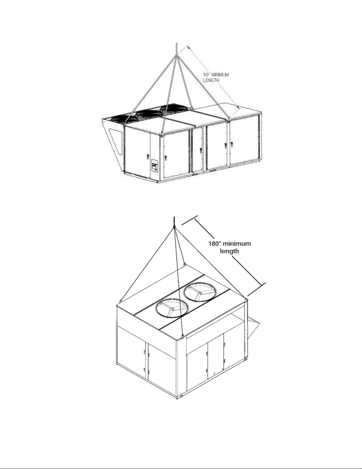
Figure 11 - Lifting Details of a 6-25 and 30 ton Energy Recovery Wheel or Power Return Unit
Figure 12 - Lifting Details of a 26, 31-50, 60 and 70 ton Unit
39
Page 40

Figure 13 - Lifting Details of a 55, 65 and 75-140 ton Unit
40
Page 41

Do not drill or punch holes in the
base of the unit, from inside the unit
or from below the unit to attach
ductwork. Leaking may occur if unit
base is punctured.
CAUTION
Duct Connection
Note: If outside air will be in contact with
the air tunnel base of an A, B or C cabinet
unit (6-25 and 30 tons), the unit should
include the base insulation option or the
base must be field insulated. D and E
cabinet (26 and 31-140 tons) units include
base insulation standard.
Figure 14 - Duct Connection
41
Page 42

Seismic Curb Installation
Using a standard curb with a seismic unit
will void the certification of the unit. All
mounting details listed must be followed to
achieve seismic certification. The AAON
unit must be certified to ICC-ES AC156
when using a seismic curb for seismic
certifications to apply. Any deviations or
modifications to the unit or curb will void all
seismic certification.
Structural engineer of record must approve
field provided building anchorage to unit or
curb in compliance with OSP-0180-10. Use
provided self tapping screws to attach base
of unit to seismic curb bracket.
42
Figure 15 - Solid Bottom Seismic Curb with Filters
Page 43
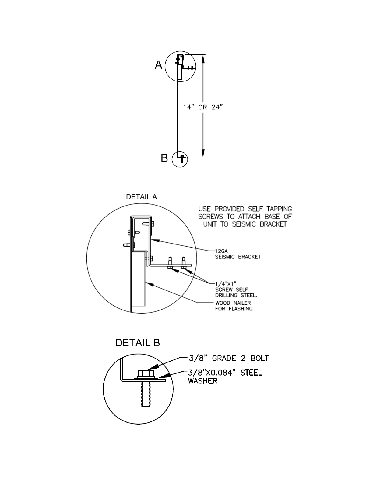
Figure 16 - Seismic Solid Bottom Curb without Filters Cross Section
Figure 17 - Seismic Solid Bottom Curb without Filters Detail A
Figure 18 - Seismic Solid Bottom Curb without Filters Detail B
43
Page 44

Figure 19 - Seismic Rigid Mount Curb
44
Page 45

Condenser Hail Guards
90-140 ton Units
Condenser hail guards fold down and
become a condenser coil shipping cover on
90-140 ton RN Series units with copper tube
and aluminum fin condenser coils.
Condenser hail guards must be opened
before startup of the unit.
Figure 20 - 90-140 ton Condenser Coil Guard Installation Instructions 1
45
Page 46

Figure 21 - 90-140 ton Condenser Coil Guard Installation Instructions 2
Outside Air Rain Hood
Rain hood must be opened before startup of
the unit. Fresh air intake adjustments should
be made according to building ventilation of
local code requirements.
6-25 and 30 ton Units
Remove the two screws at the bottom of the
rain hood that secure it in the shipping
46
position. Remove the screws that attach the
side pieces of the hood to the top of the
hood.
Rotate the side pieces so that the holes along
one edge line up with the holes on the top
piece and the flange is on the inside of the
rain hood.
Page 47

Attach the side pieces to the top of the hood
using the provided screws and attached the
side pieces to the end of the unit through the
flange.
Apply silicon caulking along the top and
both sides of the rain hood. Take care to seal
the top corners where the rain hood attaches
to the unit.
26 and 31-140 ton Units
Remove the shipping screws from each side
of the closed hood.
Lift hood outward and attach the sides of the
hood to the side of the unit.
Apply silicon caulking along the top and
both sides of the rain hood. Take care to seal
the top corners where the rain hood attaches
to the unit.
Figure 22 - 6-25 and 30 ton
Closed Rain Hood
Figure 23 - 6-25 and 30 ton
Open Rain Hood
Figure 24 - 26 and 31-140 ton
End Flashing Installation
On RN Series E cabinet units that are 142”
wide (RN-55, 65, 75, 90, 105, 120, 130,
140) the cabinet width will overhang the
shipping trailer on each side.
In order to secure and protect the unit during
transit the sheet metal end flashings have
been removed from the unit. The slot created
at the base of each end of the unit allows the
unit to set firmly on the trailer deck.
Sheet metal flashings are shipped loose with
the unit and once the unit is set into place
the flashings must be installed on each end
of the unit to complete the finished seal at
the base. The flashings are unit specific and
designed to cover the slot at each end of the
unit to prevent water run-off into the curb.
Open Rain Hood
47
Page 48
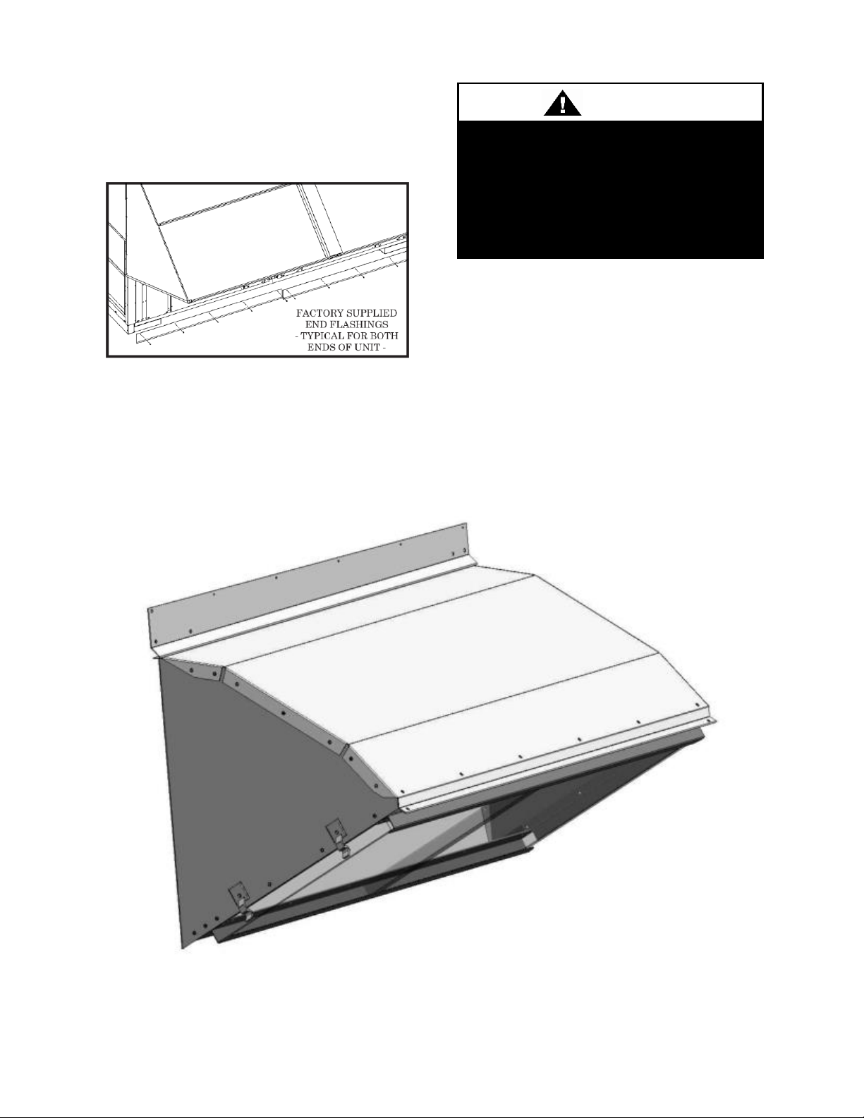
In order to prevent water leakage into
the roof curb, the factory provided
sheet metal flashings MUST BE
attached to the unit base to cover the
shipping slots at both ends of the
unit.
CAUTION
Failure to attach and seal the end of unit
with the flashings may result in water
leakage into the curb.
Figure 25 - Factory Supplied End Flashings
Metal Mesh Filters (6-25 and 30 ton Units)
Metal mesh outside air filters require
installation of the filter rack on the intake of
the rain hood.
Clips which hold the metal mesh filters in
the filter rack should face outward.
Figure 26 - Rain Hood with Metal Mesh Filter Rack Installation
48
Page 49

Electric shock hazard. Before
attempting to perform any installation,
service, or maintenance, shut off all
electrical power to the unit at the
disconnect switches. Unit may have
multiple power supplies. Failure to
disconnect power could result in
dangerous operation, serious injury,
death, or property damage.
WARNING
Installing Contractor is responsible
for proper sealing of the electrical
and gas entries into the unit Failure
to seal the entries may result in
damage to the unit and property.
CAUTION
Electrical
Verify the unit nameplate agrees with power
supply. Connect power and control wiring to
the unit as shown in Figure I12 and in the
unit specific wiring diagram, which shows
factory and field wiring and is attached to
the inside of the door of the controls
compartment.
Route power and control wiring, separately,
through the utility entry in the base of the
unit. Do not run power and control signal
wires in the same conduit. The utility entry
on 9-25 and 30 ton units is located in the
unit base in the front right hand corner of the
unit (compressor compartment). The utility
entry on 26 and 31-70 ton units is located in
the unit base in the front left hand corner in
the unit (controls compartment). The utility
entry on 55, 65 and 75-140 ton units is
located in the center front of the unit. See
unit drawing for specific location.
Figure 27 - Unit Utility Entry
Figure 28 - Back View of Power Switch
from Compressor and Control Compartment
(6-50, 60, and 70 ton Units)
49
Page 50

Three phase voltage imbalance will
cause motor overheating and
premature failure.
CAUTION
Figure 29 - Front View of Utility Entry and
Power Switch from Control Compartment
(55, 65 and 75-140 ton Units)
Size supply conductors based on the unit
MCA rating. Supply conductors must be
rated a minimum of 75°C.
Protect the branch circuit in accordance with
code requirements. The unit must be
electrically grounded in accordance with
local codes, or in the absence of local codes,
the current National Electric Code,
ANSI/NFPA 70 or the current Canadian
Electrical Code CSA C22.1.
Note: All units are factory wired for 208V,
230V, 460V, or 575V. The transformer
configuration must be checked by a
qualified technician prior to service,
especially if unit is to be connected to a
208V or 230V supply. For 208V service
interchange the yellow and red conductor on
the low voltage control transformer.
Red-Black for 208V
Yellow-Black for 230V
Wire power leads to the unit’s terminal
block or main disconnect. All wiring beyond
this point has been completed by the
manufacturer and cannot be modified
50
without effecting the unit’s agency/safety
certification.
Supply voltage must be within the min/max
range shown on the unit nameplate.
Available short circuit current should not
exceed the short circuit current rating
(SCCR) shown on the unit nameplate.
Three phase voltage imbalance will cause
motor overheating and premature failure.
The maximum allowable imbalance is 2.0%.
Voltage imbalance is defined as 100 times
the maximum deviation from the average
voltage divided by the average voltage.
Example:
(221V+230V+227V)/3 = 226V, then
100*(226V-221V)/226V = 2.2%, which
exceeds the allowable imbalance.
Check voltage imbalance at the unit
disconnect switch and at the compressor
terminal. Contact your local power company
for line voltage corrections.
Installing contractor must check for proper
motor rotation and check blower motor
amperage listed on the motor nameplate is
not exceeded. Motor overload protection
may be a function of the variable frequency
drive and must not be bypassed.
Page 51

Model (RN-)
Compressor VFD
Range (Hz)
208V and 230 V Units
055, 065 & 075-140
35-60 Hz
460V and 575V Units
055, 065, 075, 090,
120, 130
35-75 Hz
105, 140
35-60 Hz
Wire Size (Stranded)
- Copper Conductors
Only
Total Wire Distance
Allowable
20 AWG
200 ft
18 AWG
350 ft
16 AWG
500 ft
14 AWG
750 ft
12 AWG
1250 ft
Rotation must be checked on all
MOTORS AND COMPRESSORS of
three phase units. Supply fan,
exhaust fan, return fan, and
condenser fan motors should all be
checked by a qualified service
technician at startup and any wiring
alteration should only be made at the
unit power connection.
CAUTION
Scroll compressors are directional
and will be damaged by operation in
the wrong direction. Low pressure
switches on compressors have been
disconnected after factory testing.
Rotation should be checked by a
qualified service technician at startup
using suction and discharge pressure
gauges and any wiring alteration
should only be made at the unit
power connection.
CAUTION
No variable speed compressor shall
operate below 35 Hz. Operating
variable speed compressors outside
the frequency range specified in this
manual voids all warranties and may
result in compressor failure.
CAUTION
Wire control signals to the unit’s low
voltage terminal block located in the
controls compartment.
If any factory installed wiring must be
replaced, use a minimum 105°C type AWM
insulated conductors.
Variable Speed Compressors
Variable speed compressors with VFD
speed control are available on 55, 65 and 75140 ton units. Variable speed compressors
should not be operated outside the factory
determined frequency range. The factory
determined compressor VFD frequency
range is given below in Table 7.
Table 7 - Variable Speed Compressor VFD
Frequency Range
Thermostat Control Wiring
If a thermostat is used for unit control,
thermostat should be located on an inside
wall 4-5 feet above the floor where it will
not be subjected to drafts, sun exposure, or
heat from electrical fixtures of appliances.
Control wiring must deliver adequate
voltage to components to assure proper
operation. Control voltage returning from
controller circuit must be a minimum of 21
VAC. To assure proper wiring use the
following chart to determine the allowable
wiring distances.
Table 8 - Control Wiring
51
Page 52

Model
Option
B2
Input
MBH
Connections
Quantity
Size
2
90.0
1
1/2” NPT
K
150.0
L
210.0
3/4” NPT
Model
Option
B2
Input
MBH
Connections
Quantity
Size
F
195.0
1
3/4” NPT
G
292.5
6
390.0
Model
Option
B2
Input
MBH
Connections
Quantity
Size
4
270
1
3/4” NPT
8
405
1” NPT
C
540
Model
Option
B2
Input
MBH
Connections
Quantity
Size
*A
540
2
3/4” NPT
*B
780
C
540
1
1-1/2”
NPT
D
810
E
1080
FOR YOUR SAFETY
Read the entire gas heating
installation section of this manual
before beginning installation of the
gas heating section.
If you do not follow these instructions
exactly, a fire or explosion may result
causing property damage, personal
injury, or loss of life.
WARNING
Total Wire Distance Allowable =
(Quantity of Control Wires) x
(Control Wire Distance)
Take the total wire distance allowable and
divide by the quantity of wires to be
connected. This indicates the distance
allowable for that size wire. The wiring to
the unit must not exceed the total wire
distance allowable. If the voltage at the
connectors is less than 21 VAC, isolation
relays must be installed. If under external
control 21 VAC must be field verified.
All external devices must be powered via a
separate external power supply.
Example:
A total of 8 wires must be pulled 75ft to a
control the unit. What size wire should be
used?
According to the Table 8, 16 AWG allows
for 63ft (500 ft/8 wires) and 14 AWG allows
for 94ft (750 ft/8 wires). Thus, 14 AWG
should be used.
Gas Heating
Verify the unit nameplate agrees with the
proper gas supply type and amount.
52
Gas piping must be installed in accordance
with local codes, or in the absence of local
codes, installation must conform to the
current (United States) National Fuel Gas
Code ANSI-Z223.1/NFPA 54 or the current
(Canada) National Fuel & Propane
Installation Code CSA B149.1 or B149.2.
Table 9 - 6-8 and 10 ton Gas Connections
Table 10 - 9 and 11-15 ton Gas Connections
Table 11 - 16-25 and 30 ton
Gas Connections
Table 12 - 26 and 31-70 ton
Gas Connections
*Obsolete
Page 53
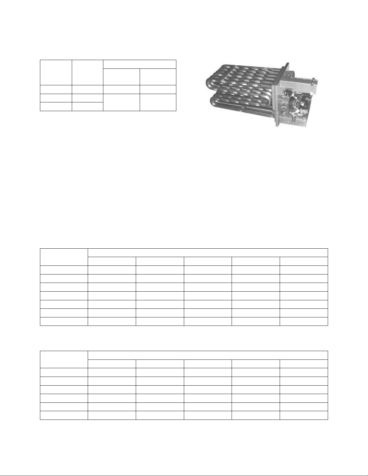
Model
Option
B2
Input
MBH
Connections
Quantity
Size
M
800
2
1” NPT
N
1600
2
1-1/2”
NPT
P
2400
Pipe Size
Length of Pipe
20 ft
50 ft.
100 ft.
150 ft.
200 ft.
1/2”
120
73
50
40
35
3/4”
250
151
103
84
72
1”
465
285
195
160
135
1-1/4”
950
580
400
325
280
1-1/2”
1460
900
620
500
430
2”
2750
1680
1150
950
800
2-1/2”
4350
2650
1850
1500
1280
Pipe Size
Length of Pipe
20 ft
50 ft.
100 ft.
150 ft.
200 ft.
1/2”
189
114
78
63
55
3/4”
393
237
162
132
112
1”
732
448
307
252
213
1-1/4”
1496
913
630
511
440
1-1/2”
2299
1417
976
787
675
2”
4331
2646
1811
1496
1260
Table 13 - 55, 65 and 75-140 ton Gas
Connections
After verifying gas inlet pressure and
manifold pressure the service technician
must time the gas flow rate through the gas
meter with a stopwatch to verify the gas
input rate.
Unit nameplate input rate value has been
calculated at the altitude where the unit was
shipped. Above 2,000 ft the input rate is
adjusted 4% for every 1,000 ft.
Table 14 - Natural Gas (ft3/hr) Maximum Piping Capacities
Specific Gravity = 0.6, Supply Pressure ≤ 0.5 psi, Pressure Drop = 0.5” w.c.
Figure 30 - RN Series Gas Heat Exchanger
Table 15 - Propane (kBtu/hr) Maximum Piping Capacities
Specific Gravity = 1.52, Supply Pressure = 11” w.c., Pressure Drop, 0.5” w.c.
53
Page 54
BTU
ft
MBH
1000
1080
3
Heater should be disconnected from
the gas supply piping during pressure
testing of the supply piping system
with pressures in excess of ½ psi. Gas
valves can be damaged if subjected to
more than ½ psi.
CAUTION
Do not use gas piping smaller than unit gas
connections. Natural gas pipe runs longer
than 20 feet and propane gas pipe runs
longer than 50 feet may require a larger
supply pipe than the unit connection size.
Some utility companies may also require
pipe sizes larger than the minimum sizes
listed.
Piping Sizing Examples
A 100 ft pipe run is needed for a 1080 MBH
natural gas heater. The natural gas has a
rating of 1000 Btu/ft3 and a specific gravity
of 0.6 (Obtain these values from the local
gas supplier.)
From the natural gas maximum capacities
table, at 100 ft and 1080 ft3/hr the required
minimum pipe size is 2”.
A 100 ft pipe run is needed for a 270 MBH
propane gas heater.
270 MBH = 270 kBtu/hr
From the propane gas maximum capacities
table, at 100 ft and 270 kBtu/hr the required
minimum pipe size is 1”.
Inlet and Manifold Pressures
For natural gas units, the minimum inlet gas
pressure to the unit is 6” w.c. and maximum
inlet gas pressure to the unit is 10.5” w.c.
For propane units, the minimum inlet gas
pressure to the unit is 11” w.c. and the
maximum inlet gas pressure to the unit is
13” w.c. A field provided 1/8” NPT pressure
tap is required to be installed in the piping
just upstream of the shutoff valve for test
gage connection to allow checking of the
gas supply pressure at the unit.
A factory installed pressure tap on the outlet
end of the gas valve can be used to verify a
54
1080 ft3/hr
manifold pressure of 3.5” w.c. for natural
gas, or 10.5” w.c. for propane.
Gas Pressure Regulator & Overpressure Protection Device
A gas pressure regulator must be installed if
natural gas supply pressure to the unit is
greater than 10.5” w.c. and less than 2 psi
(55.4” w.c.) and if propane gas supply
pressure is greater than 13” w.c. and less
than 2 psi (55.4” w.c.). Regulators must
comply with the latest edition of the
Standard for Line Pressure Regulators,
ANSI Z21.80/CSA 6.22.
Both a gas pressure regulator and
overpressure protection device (OPD) must
be installed if gas supply pressure to the unit
is greater than 2 psi (55.4” w.c.) and less
than 5 psi (138.4” w.c.), in compliance with
ANSI Z21.80/CSA 6.22. For proper heater
operation, pressure to the regulator MUST
NOT be greater than 5 psi (138.4” w.c.).
Piping Supports
Gas supply piping must be supported
directly at the connection to the unit and at
intervals listed in the following table with
metal straps, blocks, or hooks. Piping should
not be strained or bent.
Page 55

Pipe Size
Support Intervals
1/2” to 3/4”
Every 6 ft
3/4” to 1”
Every 8 ft
1-3/4” or Larger
(Horizontal)
Every 10 ft
1-1/4” or Larger
(Vertical)
Every Floor
Table 16 - Gas Piping Supports
Additional Gas Piping Considerations
Local codes will usually require a field
provided and installed manual main shutoff
valve and union external to the unit. Main
shutoff valve should be labeled. A drip leg
should be installed near the unit connection
to trap sediment and condensate. Pipe joint
compounds used on all gas piping
connections should be resistant to liquid
petroleum gases. If flexible gas piping to the
unit, or in the unit, must be replaced
connectors cannot be reused, only new
connectors may be used.
Heat exchanger comes equipped with a
condensate drain which should be plumbed
to the appropriate drain according to the
(United States) National Fuel Gas Code
ANSI-Z223.1/NFPA 54 or the current
(Canada) National Fuel & Propane
Installation Code CSA B149.1 or B149.2,
the International Building Code, and any
applicable local and regional codes and
regulations.
The condensate drain connection is located
next to the gas entry location. For 6-50, 60
and 70 ton units, the heat exchanger
condensate drain connection from the unit is
a 5/8” barbed nylon elbow connection. For
55, 65 and 75-140 ton units, the heat
exchanger condensate drain connection from
the unit is a 1/2” PVC connection. For 55,
65 and 75-140 ton units, the heat exchanger
condensate drain can be tied into the
evaporator condensate drain, if code allows.
55
Page 56

Do not use open flame or other
source of ignition for leak testing. Fire
or explosion could result causing
property damage, personal injury, or
death.
DANGER
LEAK CHECK GAS PIPE
The gas pipe in the unit should be
checked for leaks before startup.
Leak checking is the responsibility of
the installing contractor. All
connections should be checked for
leaks annually after installation.
Failure to leak check could result in
fire, explosion, or other hazardous
situations.
DANGER
Some soaps used for leak detection
can be corrosive to certain metals.
Rinse piping thoroughly after leak
test has been completed.
CAUTION
Figure 31 - Example 6-25 and 30 ton through the Base Gas Piping
Leak Testing
All components of gas supply system,
including manual shut off valves and the
piping in the interior of the unit, should be
leak tested with a soap solution before
operating the appliance and at least on an
annual basis thereafter.
56
Page 57

Those sensitive to odors or gases
from trace amounts of residual oils
should NOT be present in the
conditioned space during the startup
of a gas fired installation.
WARNING
All gas fired heat exchangers are completely
tested at the factory before shipment. This
will remove nearly all of the oils that have
been used in the manufacturing process.
However, trace amounts may remain. When
performing the initial startup at the jobsite, it
is highly recommended that people or any
other living animals, which may be sensitive
to the residual odors or gases, NOT be
present in the conditioned space during the
startup. In all cases, including the initial
factory firing and testing, any of the gases
will be under the acceptable level of
concentration for human occupancy.
57
Page 58
OPEN LOOP APPLICATIONS
SMO 254 brazed plated refrigerantto-water heat exchangers are
recommended with all open loop
applications. Failure to use a SMO
254 heat exchanger may result in
premature failure of your system and
possible voiding of the warranty.
WARNING
OPEN LOOP APPLICATIONS
Failure of the condenser as a result
of chemical corrosion is excluded
from coverage under AAON Inc.
warranties and the heat exchanger
manufacturer’s warranties.
WARNING
WATER-SOURCE HEAT
PUMP APPLICATIONS
Water-source heat pump units using
100% outside air must have electric
preheat if the application has a
potential for heat pump heating
operation with air entering the indoor
coil below 43°F with an entering
water loop temperature of 70°F.
CAUTION
Refrigerant-to-Water Heat Exchanger
Condenser water pump, condenser water
piping, cooling tower or geothermal loop,
pressure gauges, strainers, piping insulation
and all components of the waterside piping
must be field installed.
Water-Source Heat Pump Applications
Water-source heat pump units using 100%
outside air must have electric preheat if the
application has a potential for operation with
air entering the indoor coil below 43°F with
a water loop temperature of 70°F.
Open Loop Applications
This product contains one or more
refrigerant-to-water heat exchangers made
of 316 Stainless Steel. 316 Stainless Steel is
subject to severe corrosion and failure when
exposed to chlorides.
Do not allow water containing any form of
chlorides to enter this heat exchanger.
58
Common forms of chlorides include:
1. Sea water mist entering an open cooling
tower system.
2. Contaminated makeup water containing
salt water.
3. Disinfecting the water loop with solutions
containing sodium hypochlorite.
Chlorides will result in a premature failure
of the condenser.
Failure of the condenser as a result of
chemical corrosion is excluded from
coverage under AAON warranties and the
heat exchanger manufacturer warranties.
Failure of the condenser will allow water to
enter the refrigerant circuit and will cause
extensive damage to the refrigerant circuit
components. Any damage to the equipment
as a result of condenser failure from
chemical corrosion due to the fluid in the
condenser is excluded from coverage under
AAON warranties and the heat exchanger
manufacturer warranties.
Page 59
% Glycol
Ethylene
Glycol
Propylene
Glycol
20
18°F
19°F
30
7°F
9°F
40
-7°F
-6°F
50
-28°F
-27°F
Cleaning the cooling tower or
condenser water loop with harsh
chemicals such as hydrochloric acid
(muriatic acid), chlorine or other
chlorides, can damage the
refrigerant-to-water heat exchanger.
Care should be taken to avoid
allowing chemicals to enter the
refrigerant-to-water heat exchanger.
See Appendix A - Heat Exchanger
Corrosion Resistance for more
information.
CAUTION
WATER FREEZING
Failure of the condenser due to
freezing will allow water to enter the
refrigerant circuit and will cause
extensive damage to the refrigerant
circuit components. Any damage to
the equipment as a result of water
freezing in the condenser is excluded
from coverage under AAON
warranties and the heat exchanger
manufacturer warranties.
WARNING
Freezing Water in the Heat Exchanger
This product contains one or more
refrigerant-to-water heat exchangers. A
refrigerant-to-water heat exchanger contains
refrigerant in one passage and water in
another passage. Water is subject to freezing
at 32°F. When water freezes in a heat
exchanger significant forces are exerted on
the components of the heat exchanger where
the water is confined.
Failure of the condenser due to freezing will
allow water to enter the refrigerant circuit
and will cause extensive damage to the
refrigerant circuit components. Any damage
to the equipment as a result of water
freezing in the condenser is excluded from
coverage under AAON warranties and the
heat exchanger manufacturer warranties.
Unit is capable of operating with Entering
Water Temperatures (EWT) as low as 57°F,
during the cooling mode, without the need
for head pressure control. If the EWT is
expected to be lower than 57°F or a more
stable operation is desired, a factory
provided head pressure control water valve
option is available.
Glycol solution should be used if ambient
temperatures are expected to fall below
freezing or if the loop entering water
temperature to the unit is below 50°F while
operating in the heating mode (heat pump
units only). Adding glycol to condenser water
causes an increase in pressure drop and also
results in a decrease in unit performance. A
minimum concentration of 20% glycol
solution is recommended.
Table 17 - Glycol Freezing Points
Water loop piping runs through unheated
areas or outside the building should be
insulated.
Water Piping
Installing contractor must ensure a
differential pressure switch or water flow
switch is installed between the condenser
water supply and return connections. This
sensor provides a signal to the unit
controller that water flow is present in the
refrigerant-to-water heat exchanger and the
59
Page 60

Model (RN-)
Supply and Return
Connection Size
006, 007
1” NPT
008, 010, 009, 011,
013, 015, 016, 018,
020
1 1/2” NPT
025, 030
2” NPT
026, 031, 040
2 1/2” Grooved Pipe
050, 055, 060, 070
3” Grooved Pipe
065, 075, 090, 105
4” Grooved Pipe
120, 130, 140
5” Grooved Pipe
Model (RN-)
Supply and Return
Connection Size
016, 018, 020, 025,
030
1 1/2” NPT
WATER PRESSURE
Prior to connection of condensing
water supply, verify water pressure is
less than maximum pressure shown
on unit nameplate. To prevent injury
or death due to instantaneous
release of high pressure water, relief
valves should be field supplied on
water piping. Supply water
connection may require a backflow
preventer to prevent supply makeup
water from backing up into the public
water system.
WARNING
WATER PIPING
Follow national and local codes when
installing water piping. Connections
to the unit should incorporate
vibration eliminators to reduce noise
and vibration and shutoff valves to
facilitate servicing. Supply and return
water piping must be at least as large
as the unit connections and larger
depending on length of runs, rise and
bends.
CAUTION
unit can operate without damaging unit
components.
Table 18 - Standard Brazed Plate Heat
Exchanger Water Connections
Table 19 - SMO 254 Brazed Plate Heat
Exchanger Water Connections
Only use approved water pipe material.
Avoid using galvanized material for water
lines/fittings as the material is corrosive and
may cause fouling of the water system.
60
Condenser water pump must be field sized
and installed between the cooling
tower/geothermal loop and self-contained
unit. System should be sized in accordance
with the ASHRAE Handbook. Use
engineering guidelines to maintain equal
distances for supply and return piping and
limit bend radiuses to maintain balance in
the system. Balancing valves, permanent
thermometers and gauges may be required.
Before connection to the unit the condenser
water system should be flushed to remove
foreign material that could cause condenser
fouling. Install a screen strainer with a
minimum of 20 Mesh ahead of the
condenser inlet to prevent condenser fouling
and internal tube damage.
Mineral content of the condenser water must
be controlled. All makeup water has
minerals in it and as the water is evaporated
in the cooling tower, these minerals remain.
As the mineral content of the water
increases, the conductivity of the water
increases.
Field provided and installed water treatment
program must be compatible with stainless
steel, copper, aluminum, ABS plastic, and
PVC. Batch feed processes should never be
Page 61

Each heat exchanger is equipped
with a refrigerant pressure relief
device to relieve pressure should
excessive condensing pressures
(>675 psig) occur. Codes may
require installing contractor to
connect and route relief piping
outdoors. The relief valve has a 5/8”
male flare outlet connection.
CAUTION
Installing contractor is responsible for
properly sizing and installing water
system components. Improper fluid
flow due to valves, piping, or
improper pump operation may result
in unacceptable unit operation and
void warranty.
CAUTION
PVC (Polyvinyl Chloride) and CPVC
(Chlorinated Polyvinyl Chloride) are
vulnerable to attack by certain
chemicals. Polyolester (POE) oils
used with R-410A and other
refrigerants, even in trace amounts,
in a PVC or CPVC piping system will
result in stress cracking of the piping
and fittings and complete piping
system failure.
CAUTION
used as concentrated chemicals can cause
corrosion. Never use hydrochloric acid
(muriatic acid) or chlorine as it will corrode
stainless steel.
NOTE: Ball valves should be installed in
the condenser water supply and return lines
for unit isolation and water flow balancing.
All manual flow valves should be of the ball
valve design. Globe or gate valves should
not be used due to high pressure drops and
poor throttling characteristics.
Pressure and temperature ports are
recommended in condenser water supply
and return lines for system balancing. These
openings should be 5 to 10 pipe diameters
from the unit water connections. To allow
for mixing and temperature stabilization,
wells in the water piping should extend at
least ½ pipe diameter into the pipe.
Piping systems should not exceed 10 ft/sec
fluid velocity to ensure tube wall integrity
and reduce noise.
Condensate Drain Piping
6-25 and 30 ton units are equipped with one
condensate drain pan connection, on the
right side of the unit, and are furnished with
a p-trap for field installation. 26 and 31-140
ton units are equipped with two condensate
drain connections, one on the left side of the
unit and one on the right side of the unit, and
are furnished with two p-traps for field
installation.
All drain connections must be used and
individually trapped to ensure a minimum
amount of condensate accumulation in the
drain pans. ABS type cement should be used
to join the drain pipe connections.
Drainage of condensate directly onto the
roof may be acceptable in certain areas, refer
to local codes. If condensate is to drain
directly onto the roof a small drip pad
should be placed below the drain to protect
the roof from possible damage.
If condensate is piped into the building
drainage system, the drain pipe should
61
Page 62
Model (RN-)
Steam Coil
Connection Size
006-140
2 1/8”
Model (RN-)
Hot Water Coil
Connection Size
006, 007, 008, 009, 010,
011, 013, 015
1 3/8”
016, 018, 020, 025, 030
1 5/8”
026, 031, 040, 050, 060,
070
2 1/8”
(standard)/
1 3/8” (preheat
coil)
055, 065, 075, 090, 105,
120, 130, 140
2 1/8”
Model (RN-)
Chilled Water
Coil Connection
Size
006, 007, 008, 009, 010,
011, 013, 015
1 5/8”
016, 018, 020, 025, 030
2 1/8”
026, 031, 040
2 5/8”
050, 055, 060, 065, 070,
075, 090, 105, 120, 130,
140
2 1/8”
Unit should not be operated without a
p-trap. Failure to install a p-trap may
result in overflow of condensate
water into the unit.
CAUTION
Piping shall be in accordance with
national and local codes. Pressure
limiting devices, backflow preventers
and all other safety requirements are
the sole responsibility of the installing
contractor.
WARNING
penetrate the roof external to the unit itself.
The drain line should be pitched away from
the unit at least 1/8 inch per foot. On longer
runs an air break should be used to ensure
proper drainage.
Draw-through cooling coils will have a
negative static pressure in the drain pan area.
This will cause an un-trapped drain to back
up due to air being pulled up through the
condensate drain piping.
Condensate drain trapping and piping should
conform to all applicable governing codes.
Heating Coils
One or two row hot water and steam heating
and preheating coils can be factory installed.
All valve controls for heating operation are
field supplied and field installed. Hot water
and steam coil connections are spun copper
tube.
Water coils should not be subjected to
entering air temperatures below 38°F to
prevent coil freeze-up. If air temperature
across the coil is going to be below this
value, use a glycol solution to match the
coldest air expected.
Table 20 - Steam Coil Connection Sizes
62
Table 21 - Hot Water Coil Connection Sizes
Chilled Water Coil
Four or six row chilled water cooling coils
can be factory installed. All valve controls
for cooling operation are field supplied and
field installed. Chilled water coil
connections are spun copper tube.
Table 22 - Chilled Water Coil Connection
Sizes
Page 63
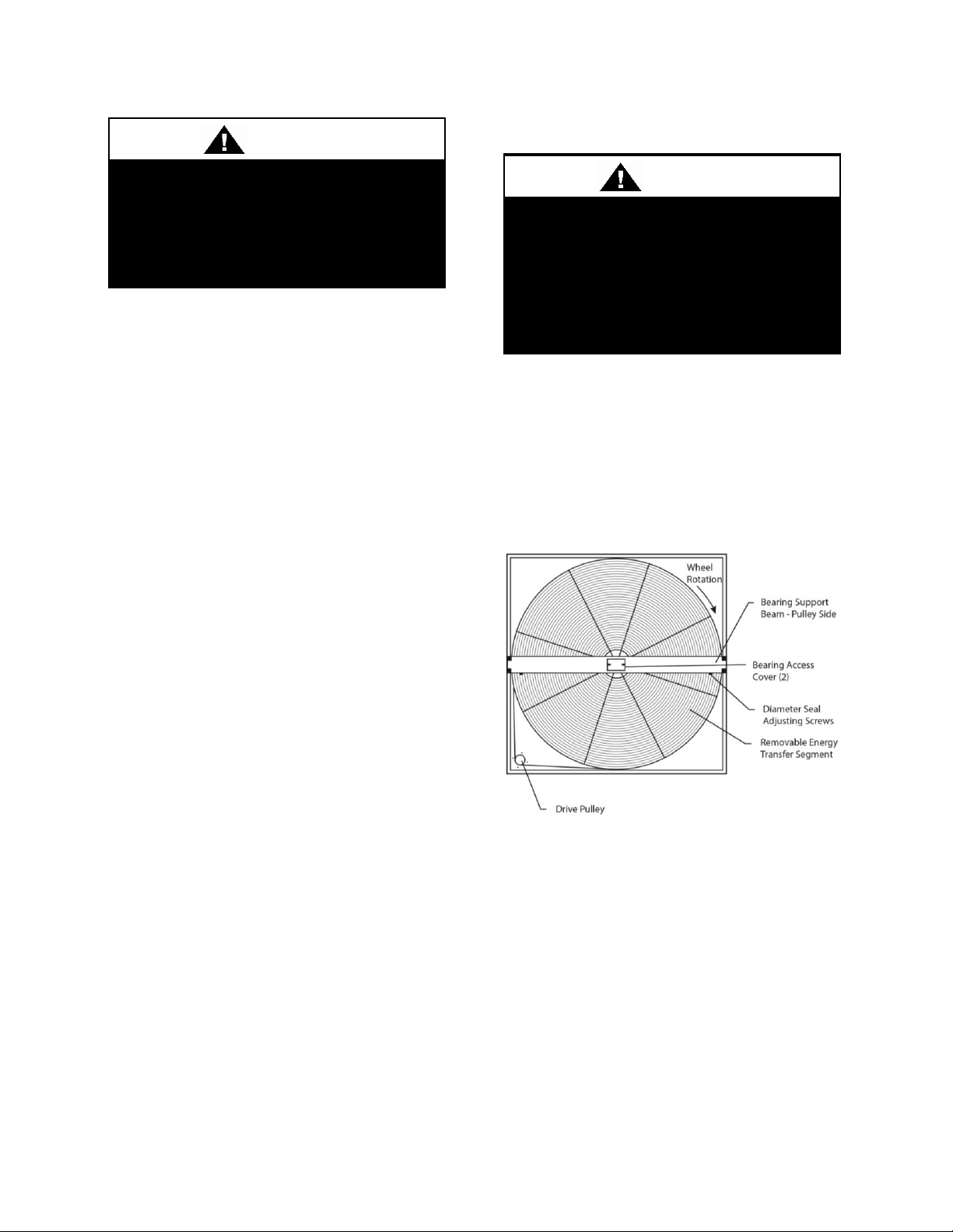
Installing Contractor is responsible
for proper sealing of the water piping
entries into the unit Failure to seal the
entries may result in damage to the
unit and property.
CAUTION
Improper installation, adjustment,
alteration, service or maintenance
can cause property damage,
personal injury or loss of life. Startup
and service must be performed by a
Factory Trained Service Technician.
WARNING
Electric Preheat
The modulating electric preheat option is
designed to temper the incoming outside air
to the unit based on an enable control signal
and the outside air conditions.
A 24VAC enable signal must be provided to
the [PHE] terminal to enable the operation
of the electric preheat. Once the preheat
controller is enabled it will monitor the
outside air temperature to determine if any
capacity of preheat is needed. If the outside
air temperature falls below the outside air
temperature setpoint the electric preheat will
be started up and maintain the leaving air
temperature setpoint with both SCR
controlled and staged electric preheat. Both
setpoints are set with push button LCD
interface on the preheat controller. Outside
air temperature sensors and preheat
discharge supply air temperature sensors are
factory installed and wired to the preheat
controller. Electric preheat has maximum
operating outside air temperature of 60°F
and a maximum preheat discharge air
temperature of 80°F.
[COM], [PHO] & [PHC] feedback terminals
are provided to communicate if the electric
preheat is in operation. PHO is a normally
open contact, PHC is a normally closed
contact, and COM is the common. These
terminals are not required to be connected.
[PHE] is the electric preheat operation
enable. [PH+] and [PH-] are the preheat set
point reset terminals.
Energy Recovery Units
General Information
AAONAIRE® units have been equipped
with an energy recovery wheel. This section
is provided to assure the energy recovery
feature will be properly setup to perform in
accordance with the job specifications for
your particular application.
Energy Recovery Wheel
The Energy Recovery Cassette consists of a
frame wheel, wheel drive system, and
energy transfer segments. Segments are
removable for cleaning or replacement. The
segments rotate through counter flowing
exhaust and outdoor air supply streams
where they transfer heat and/or water vapor
from the warm, moist air stream to the
cooler and/or drier air stream.
The initial setup and servicing of the energy
recovery wheel is very important to maintain
63
Page 64

proper operation efficiency and building
occupant comfort.
Normal maintenance requires periodic
inspection of filters, the cassette wheel,
drive belts, air seals, wheel drive motor, and
its electrical connections.
Wiring diagrams are provided with each
motor. When wired according to wiring
diagram, motor rotates clockwise when
viewed from the shaft/pulley side.
By carefully reviewing the information
within this section and following the
instructions, the risk of improper operation
and/or component damage will be
minimized.
It is important that periodic maintenance be
performed to help assure trouble free
operation.
Initial Mechanical Check and Setup
Outdoor units equipped with outside air
intake will have an outside air hood. The
outside air hood must be opened prior to unit
operation.
Outdoor air intake adjustments should be
made according to building ventilation, or
local code requirements.
After the unit installation is complete, open
the cassette access door and determine that
the energy wheel rotates freely when turned
by hand. Apply power and observe that the
wheel rotates at approximately 30 RPM. If
the wheel does not rotate when power is
applied, it may be necessary to readjust the
“diameter air seals”.
Air Seal Adjustments
Pile type air seals across both sides of the
energy wheel diameter are factory adjusted
to provide close clearance between the air
seal and wheel. Racking of the unit or
cassette during installation, and/or mounting
of the unit on a non-level support or in other
than the factory orientation can change seal
clearances. Tight seals will prevent rotation.
Cross Section of Air Seal Structure
Wheel to Air Seal Clearance
To check wheel to seal clearance; first
disconnect power to the unit, in some units
the energy recovery wheel assembly can be
pulled out from the cabinet to view the air
seals. On larger units, the energy recovery
wheel may be accessible inside the walk-in
cabinet.
A business card or two pieces of paper can
be used as a feller gauge, (typically each
.004” thick) by placing it between the face
of the wheel and pile seal.
Using the paper, determine if a loose slip fit
exist between the pile seal and wheel when
the wheel is rotated by hand.
To adjust air seal clearance, loosen all seal
plate retaining screws holding the separate
seal retaining plates to the bearing support
channels and slide the seals plates away
from the wheel. Using the paper feeler
gauge, readjust and retighten one seal plate
at a time to provide slip fit clearance when
the wheel is rotated by hand.
64
Page 65
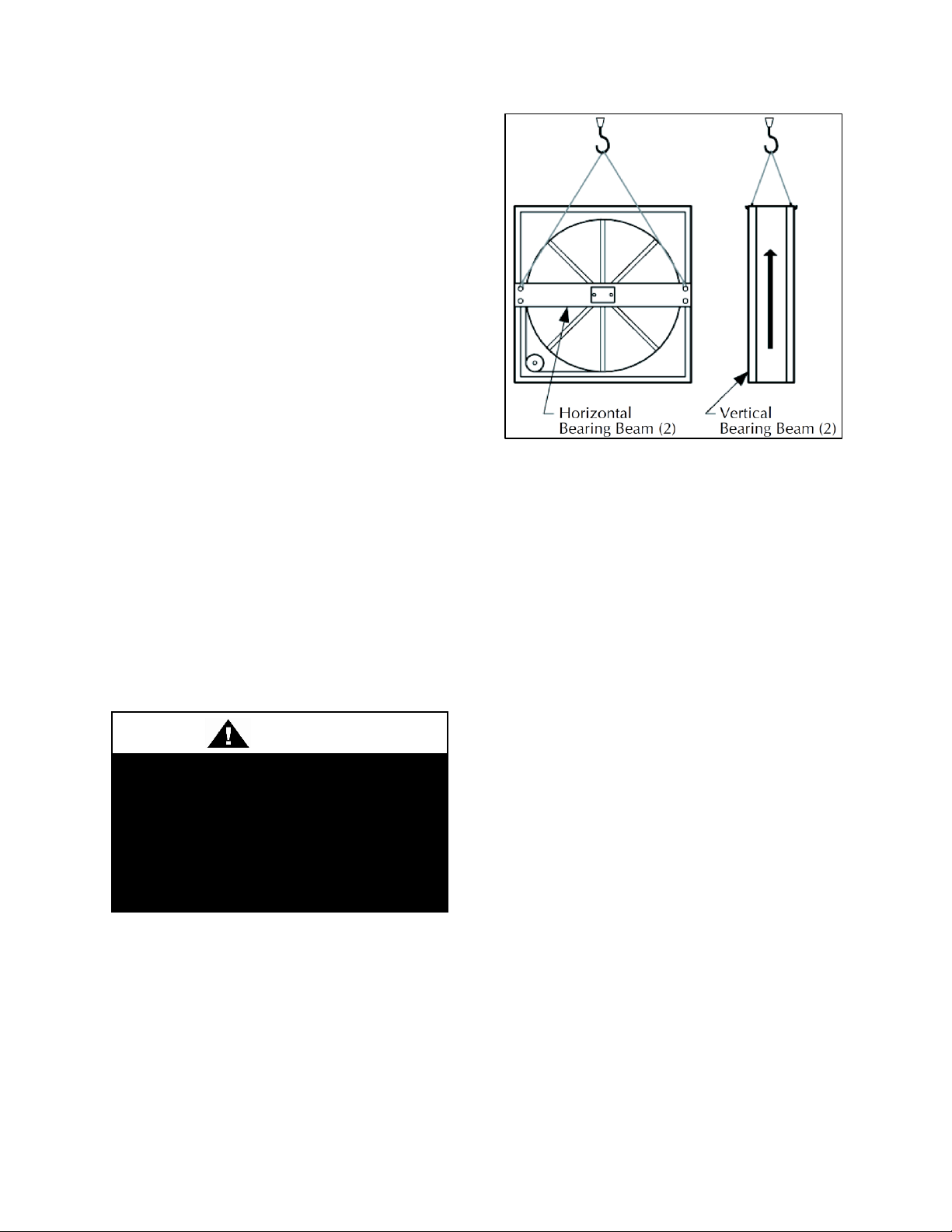
Do not alter factory wiring. Deviation
from the supplied wiring diagram will
void all warranties, and may result in
equipment damage or personal
injury. Contact the factory with wiring
discrepancies.
WARNING
Confirm that the wheel rotates freely. Apply
power to the unit and confirm rotation.
Airflow Balancing and Checking
High performance systems commonly have
complex air distribution and fan systems.
Unqualified personnel should not attempt to
adjust fan operation, or air circulation, as all
systems have unique operations
characteristics. Professional air balance
specialists should be employed to establish
actual operating conditions, and to configure
the air delivery system for optimal
performance.
Controls
A variety of controls and electrical
accessories may be provided with the
equipment. Identify the controls on each unit
by consulting appropriate submittal, or order
documents, and operate according to the
control manufacturer’s instructions. If you
cannot locate installation, operation, or
maintenance information for the specific
controls, then contact your sales
representative, or the control manufacturer
for assistance.
Routine Maintenance and Handling
Handle cassettes with care. All cassettes
should be lifted by the bearing support
beam. Holes are provided on both sides of
the bearing support beams to facilitate
rigging as shown in the following
illustration.
Lifting Hole Locations
Routine maintenance of the Energy
Recovery Cassettes includes periodic
cleaning of the Energy Recovery Wheel as
well as inspection of the Air Seals and
Wheel Drive Components as follows:
Cleaning
The need for periodic cleaning of the energy
recovery wheel will be a function of
operating schedule, climate and
contaminants in the indoor air being
exhausted and the outdoor air being supplied
to the building.
The energy recovery wheel is “self-
cleaning” with respect to dry particles due to
its laminar flow characteristics. Smaller
particles pass through; larger particles land
on the surface and are blown clear as the
flow direction is reversed. Any material that
builds up on the face of the wheel can be
removed with a brush or vacuum. The
primary need for cleaning is to remove oil
based aerosols that have condensed on
energy transfer surfaces.
A characteristic of all dry desiccants, such
films can close off micron sized pores at the
surface of the desiccant material, reducing
the efficiency by which the desiccant can
65
Page 66

Do Not use acid based cleaners,
aromatic solvents, steam or
temperatures in excess of 170°F;
damage to the wheel may occur!
CAUTION
adsorb and desorb moisture and also build
up so as to reduce airflow.
In a reasonably clean indoor environment
such as a school or office building,
measurable reductions of airflow or loss of
sensible (temperature) effectiveness may not
occur for several years. Measurable changes
in latent energy (water vapor) transfer can
occur in shorter periods of time in
applications such as moderate occupant
smoking or cooking facilities. In
applications experiencing unusually high
levels of occupant smoking or oil based
aerosols such as industrial applications
involving the ventilation of machine shop
areas for example, annual washing of energy
transfer may be necessary to maintain latent
transfer efficiency. Proper cleaning of the
energy recovery wheel will restore latent
effectiveness to near original performance.
To clean, gain access to the energy recovery
wheel and remove segments. Brush foreign
material from the face of the wheel. Wash
the segments or small wheels in a 5%
solution of non-acid based coil cleaner or
alkaline detergent and warm water.
Soak in the solution until grease and tar
deposits are loosened (Note: some staining
of the desiccant may remain and is not
harmful to performance). Before removing,
rapidly run finger across surface of segment
to separate polymer strips for better cleaning
action. Rinse dirty solution from segment
and remove excess water before reinstalling
in wheel.
66
Air Seals
Four adjustable diameter seals are provided
on each cassette to minimize transfer of air
between the counter flowing airstreams.
To adjust diameter seals, loosen diameter
seal adjusting screws and back seals away
from wheel surface. Rotate wheel clockwise
until two opposing spokes are hidden behind
the bearing support beam. Using a folded
piece of paper as a feeler gauge, position
paper between the wheel surface and
diameter seals.
Adjust seals towards wheel surface until a
slight friction on the feeler gauge (paper) is
detected when gauge is moved along the
length of the spoke. Retighten adjusting
screws and recheck clearance with “feeler”
gauge.
Wheel Drive Components
The wheel drive motor bearings are prelubricated and no further lubrication is
necessary.
The wheel drive pulley is secured to the
drive motor shaft by a combination of either
a key or D slot and set screw.
The set screw is secured with removable
locktite to prevent loosening. Annually
confirm set screw is secure. The wheel drive
belt is a urethane stretch belt designed to
provide constant tension through the life of
the belt. No adjustment is required. Inspect
the drive belt annually for proper tracking
and tension. A properly tensioned belt will
turn the wheel immediately after power is
applied with no visible slippage during startup.
Installation Considerations
Energy recovery cassettes are incorporated
within the design of packaged units,
packaged air handlers and energy recovery
Page 67

B
C
A
Bearing beams shown
racked
Frame
Wheel
Bearing
beams
Flat surface
Keep hands away from rotating
wheel! Contact with rotating wheel
can cause physical injury.
CAUTION
ventilators. In each case, it is recommended
that the following considerations be
addressed:
Accessibility
The cassette and all its operative parts; i.e.:
motor, belt, pulley, bearings, seals and
energy transfer segments must be accessible
for service and maintenance. This design
requires that adequate clearance be provided
outside the enclosure. Where cassettes are
permanently installed in a cabinet, access to
both sides of the cassette must be provided.
Orientation & Support
The Energy Recovery Cassette may be
mounted in any orientation. However, Care
must be taken to make certain that the
cassette frame remains flat and the bearing
beams are not racked.
To verify, make certain that the distance
between wheel rim and bearing beam is the
same at each end of the bearing beam, to
within 1/4 of an inch (dimension A & B).
This amount of racking can be compensated
for by adjusting the diameter seals.
If greater than 1/4 inch (dimension C),
racking must be corrected to ensure that
drive belt will not disengage from wheel.
Operation
Startup Procedure
1. By hand, turn wheel clockwise (as viewed
from the pulley side), to verify wheel turns
freely through 360º rotation.
2. Before applying power to drive motor,
confirm wheel segments are fully engaged in
wheel frame and segment retainers are
completely fastened. (See Segment
Installation Diagram).
3. With hands and objects away from
moving parts, activate unit and confirm
wheel rotation. Wheel rotates clockwise (as
viewed from the pulley side).
4. If wheel has difficulty starting, turn power
off and inspect for excessive interference
between the wheel surface and each of the
four (4) diameter seals. To correct, loosen
diameter seal adjusting screws and back
adjustable diameter seals away from surface
of wheel, apply power to confirm wheel is
free to rotate, then re-adjust and tighten hub
and diameter seals, as shown in hub seal
adjustment diagram.
5. Start and stop wheel several times to
confirm seal adjustment and to confirm belt
is tracking properly on wheel rim
(approximately 1/4” from outer edge of
rim).
Avoid Racking of Cassette Frame
67
Page 68

Disconnect electrical power before
servicing energy recovery cassette.
Always keep hands away from
bearing support beam when installing
or removing segments. Failure to do
so could result in severe injury to
fingers or hand.
CAUTION
Segment Installation & Replacement
Wheel segments are secured to the wheel
frame by a Segment Retainer which pivots
on the wheel rim and is held in place by a
Segment Retaining Catch.
Diameter Seal Adjustment
Segment Retainer
To install wheel segments follow steps one
through five below. Reverse procedure for
segment removal.
1. Unlock two segment retainers (one on
each side of the selected segment opening.
2. With the embedded stiffener facing the
motor side, insert the nose of the segment
between the hub plates.
Hub Seal Adjustment
Service
68
Segment Installation
3. Holding segment by the two outer
corners, press the segment towards the
Page 69

Protect hands and belt from possible
sharp edges of hole in Bearing
Support Beam.
CAUTION
center of the wheel and inwards against the
spoke flanges. If hand pressure does not
fully seat the segment, insert the flat tip of a
screw driver between the wheel rim and
outer corners of the segment and apply
downward force while guiding the segment
into place.
4. Close and latch each Segment Retainer
under Segment Retaining Catch.
5. Slowly rotate the wheel 180º. Install the
second segment opposite the first for
counterbalance. Rotate the two installed
segments 90º to balance the wheel while the
third segment is installed. Rotate the wheel
180º again to install the fourth segment
opposite the third. Repeat this sequence with
the remaining four segments.
Wheel Drive Motor and Pulley
Replacement
1. Disconnect power to wheel drive motor.
2. Remove belt from pulley and position
temporarily around wheel rim.
3. Loosen set screw in wheel drive pulley
using a hex head wrench and remove pulley
from motor drive shaft.
4. While supporting weight of drive motor in
one hand, loosen and remove (4) mounting
bolts.
5. Install replacement motor with hardware
kit supplied.
6. Install pulley to dimension as shown and
secure set screw to drive shaft.
7. Stretch belt over pulley and engage in
groove.
8. Follow start-up procedure.
Belt Replacement
1. Obtain access to the pulley side bearing
access plate if bearing access plates are
provided. Remove two bearing access plate
retaining screws and the access plate.
2. Using hexagonal wrench, loosen set screw
in bearing locking collar. Using light
hammer and drift (in drift pin hole) tap
collar in the direction of wheel rotation to
unlock collar. Remove collar.
3. Using socket wrench with extension,
remove two nuts which secure bearing
housing to the bearing support beam. Slide
bearing from shaft. If not removable by
hand, use bearing puller.
4. Form a small loop of belt and pass it
through the hole in the bearing support
beam. Grasp the belt at the wheel hub and
pull the entire belt down.
Note: Slight hand pressure against wheel
rim will lift weight of wheel from inner race
of bearing to assist bearing removal and
installation.
5. Loop the trailing end of the belt over the
shaft (belt is partially through the opening).
6. Reinstall the bearing onto the wheel shaft,
being careful to engage the two locating pins
into the holes in the bearing support beam.
Secure the bearing with two self-locking
nuts.
7. Install the belts around the wheel and
pulley according to the instructions provided
with the belt.
8. Reinstall diameter seals or hub seal and
tighten retaining screws. Rotate wheel in
clockwise direction to determine that wheel
rotates freely with slight drag on seals.
9. Reinstall bearing locking collar. Rotate
collar by hand in the direction the wheel
rotates (see label provided on each cassette
for wheel rotation).
10. Lock in position by tapping drift pin
hole with hammer and drift. Secure in
position by tightening set screw.
11. Reinstall Bearing Access Cover.
69
Page 70

12. Apply power to wheel and ensure that
the wheel rotates freely without interference.
Belt Replacement
70
Page 71

Electric shock hazard. Shut off all
electrical power to the unit to avoid
shock hazard or injury from rotating
parts.
WARNING
Improper installation, adjustment,
alteration, service or maintenance
can cause property damage,
personal injury or loss of life. Startup
and service must be performed by a
Factory Trained Service Technician.
WARNING
Startup
(See back of the manual for startup form.)
During startup, it is necessary to perform
routine checks on the performance of the
unit. This includes checking the air flow, air
filters, condenser water flow, dampers,
heaters, and refrigerant charge.
Supply Fans
RN Series units are equipped with direct
drive backward curved plenum fan
assemblies that are selected to deliver the air
volume specified according to unit size and
job requirements. This is either done with air
volume bands in the blower wheels or with
variable frequency drives. Field airflow
adjustment may be required at startup.
Air volume bands for the wheels are sized
according to the unit’s air delivery
specifications and can also be ordered from
the factory for field installation. Wheels
come standard with a 10% air volume band,
as a safety factor, in case additional air
volume is required from the unit.
Air Flow Adjustment
If reduced air volume is required an air
volume band or larger air volume band can
be installed within the blower wheel to
reduce the amount of air delivered by the
wheel.
If the unit is factory equipped with the air
volume band and additional air volume is
required, the band can be removed from the
wheel.
Use fan program in AAON ECat to
determine the new band size for the required
cfm and static pressure.
The following photos of a wheel are
provided for practical guidelines only in
order to identify the air band location in the
wheel. Actual field installation of the air
band into the wheel will require access into
and through the blower wheel venture,
which may require removal of the blower
motor and wheel.
Air volume bands are made of aluminum,
sized and equipped with easy bend tabs that
are to be inserted into pre-punched slots
provided on the wheel. Once the band has
been inserted into the slots, it MUST BE
secured by bending the tabs over from the
back side of the wheel and also MUST BE
secured from the inside by connecting the
ends together with a pop-rivet in the holes
provided on the ends of the band.
If the band is field installed, a hand held
pop-rivet tool is recommended for
connecting the band ends together. Caution
must be taken to assure that the band is
tightly installed and no damage, denting or
alteration to the wheel or blades occurs
during the installation.
71
Page 72

Figure 32 - Supply Fan Banding
Power Return Axial Flow Fans (16-25 and 30 tons)
Blade Pitch Angle Setting Instructions
Step 1: Determine the new required pitch for
the fan blades
Use the fan program in AAON ECat.
Step 2: Maintain the balance of fan
Mark the HUB/RET castings across a single
joint, so the fan can be reassembled in the
same orientation.
Mark the location of any balancing weight.
Balancing weight will be on the outer bolt
circle, in the form of washers, and/or longer
bolts, or an additional balancing nut.
Number the blades and blade sockets, so that
they can be replaced into their original
positions.
72
Page 73
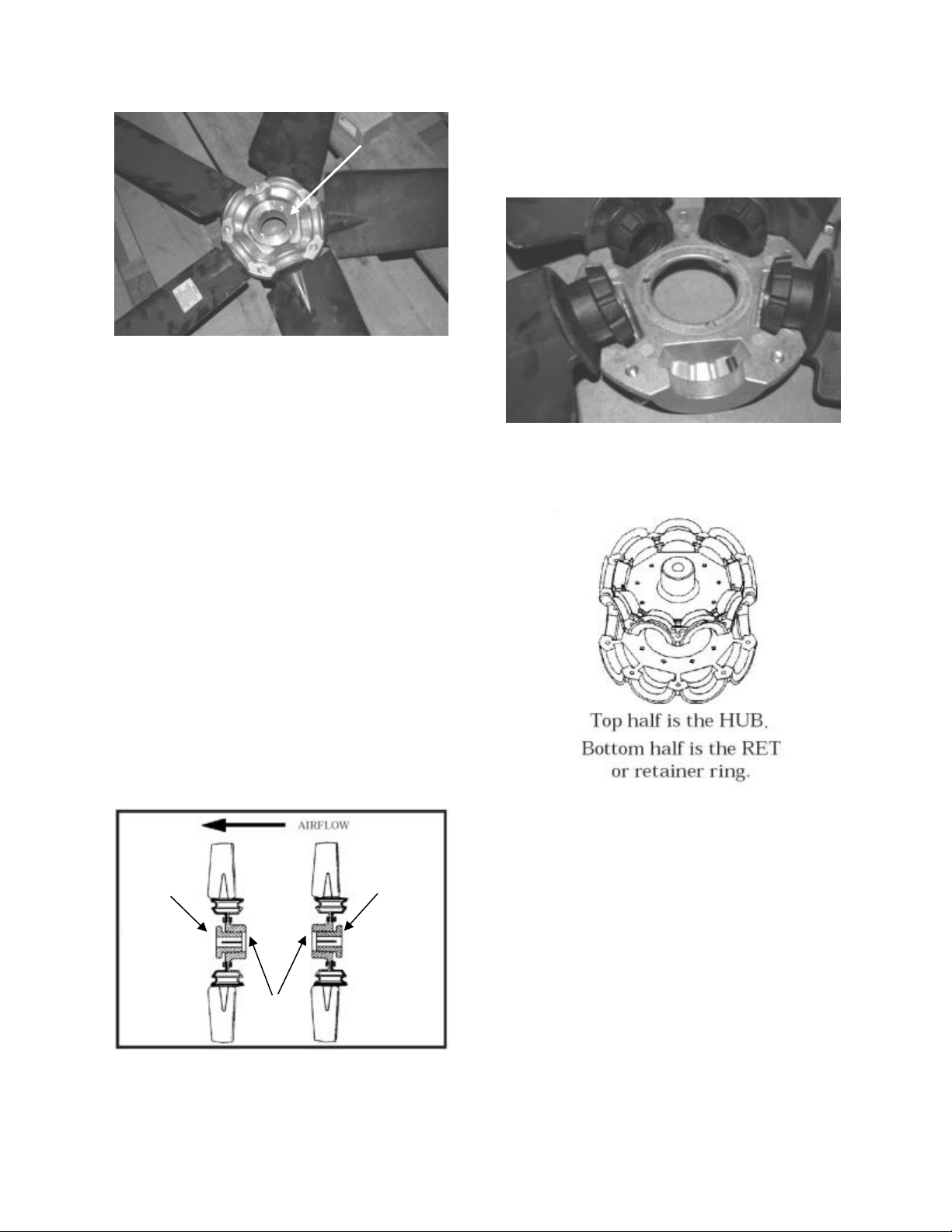
Bushing
Mount
A
B
Bushing
Mount
Bushing
Bushing
1
2
3
4
Figure 33 - Fan with the HUB on the Top
and RET on the Bottom
Step 3: Determine the direction of rotation
Right, R, is clockwise when facing the
discharge side of the fan and Left, L, is
counterclockwise when facing the discharge
side of the fan.
Step 4: Determine the bushing mount
location
The bushing mount is the center section of
the hub through which the fan is mounted to
the shaft, and typically contains either
setscrews or a center-tapered hole where the
bushing inserts.
Location A is with the bushing mount on air
inlet side of the fan.
Location B is with the bushing mount on air
discharge side of the fan.
Figure 34 - Bushing Mount Location
Step 5: Determine the pin location groove
Disassemble fan on a flat surface and note in
which groove the pin is located.
Figure 35 - RET with Pin in Groove 4
Step 6: Determine whether the pin is in the
HUB or RET
Figure 36 - Fan HUB and RET Castings
73
Page 74
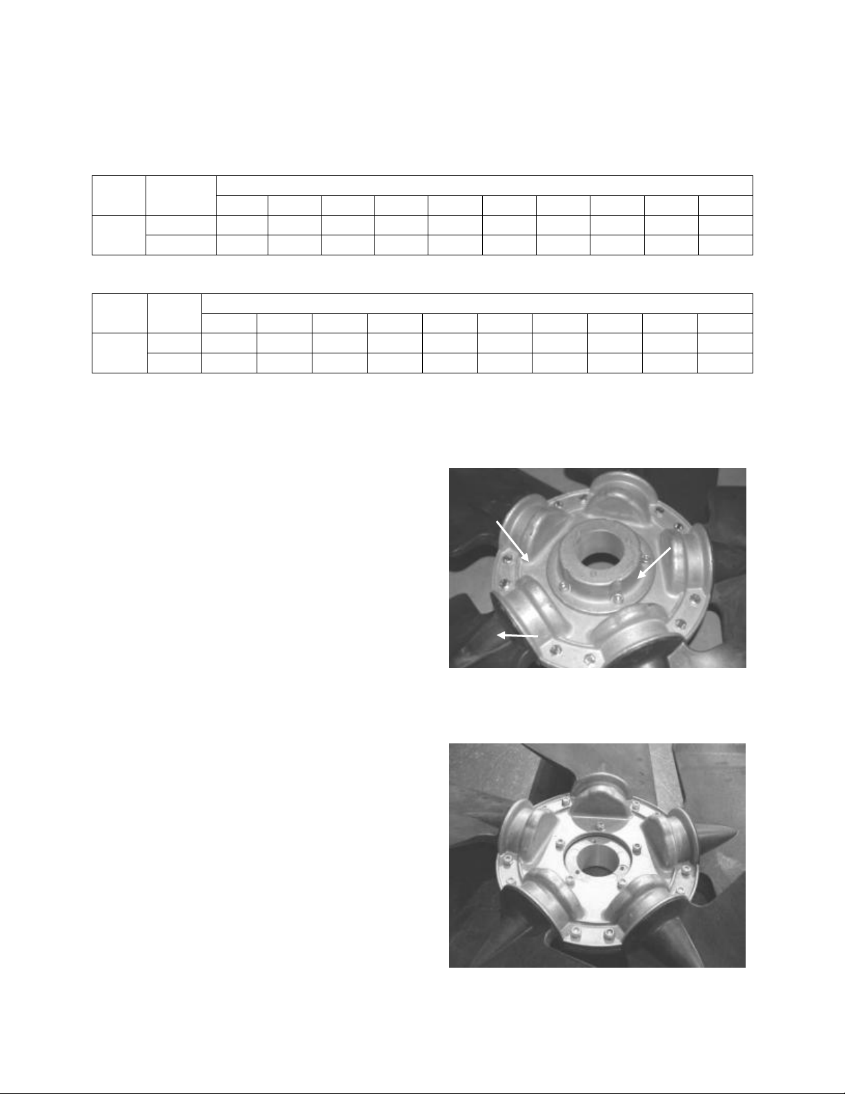
Type
Bushing
Mount
Blade Pitch Angle
20°
25°
28°
30°
33°
35°
38°
40°
45°
50°
5Z
A
-
RET
-
RET
RET
RET
HUB
HUB
HUB
HUB B -
HUB
-
HUB
HUB
HUB
RET
RET
RET
RET
Type
Rot.
Blade Pitch Angle
20°
25°
28°
30°
33°
35°
38°
40°
45°
50°
5Z
R - 4 - 3 2 1 4 3 2 1 L - 1 - 2 3 4 1 2 3
4
Bushing
Mount
Fan
Blade
Hub
Step 7: Determine the current blade pitch and the pin location for the new blades
Table 23 - Pin Location
Table 24 - Pin Groove Location
Step 8: Replace fan blades in the new pin
location and reassemble the fan
Replace the blades with the pin in the 1, 2,
3, or 4 groove position of either the HUB or
RET. Assemble the fan making sure to place
the blades in their previous blade sockets, to
match up the previous orientation of HUB
and RET and to replace any balancing
weights in their previous locations. Tighten
bolts in a cross pattern to 5-6 ft-lbs. of
torque.
Power Return and Exhaust Axial Flow Fans (26 and 31-140 tons)
Blade Pitch Angle Setting Instructions
Step 1: Determine the new required pitch for
the fan blades
Use the fan program in AAON ECat.
Contact the AAON parts department to
acquire the new pitch pins for the fan blades.
Step 2: Maintain the balance of fan
Mark the hub plate castings across a single
joint, so the fan can be reassembled in the
same orientation.
Mark the location of any balancing weight.
Balancing weight will be on the outer bolt
circle, in the form of washers, and/or longer
bolts, or an additional balancing nut.
Number the blades and blade sockets, so that
they can be replaced into their original
positions.
Figure 37 - Assembled Fan
Step 3: Remove the mounting nuts and bolts
and separate hub plate castings
Figure 38 - Back of the Fan
74
Page 75
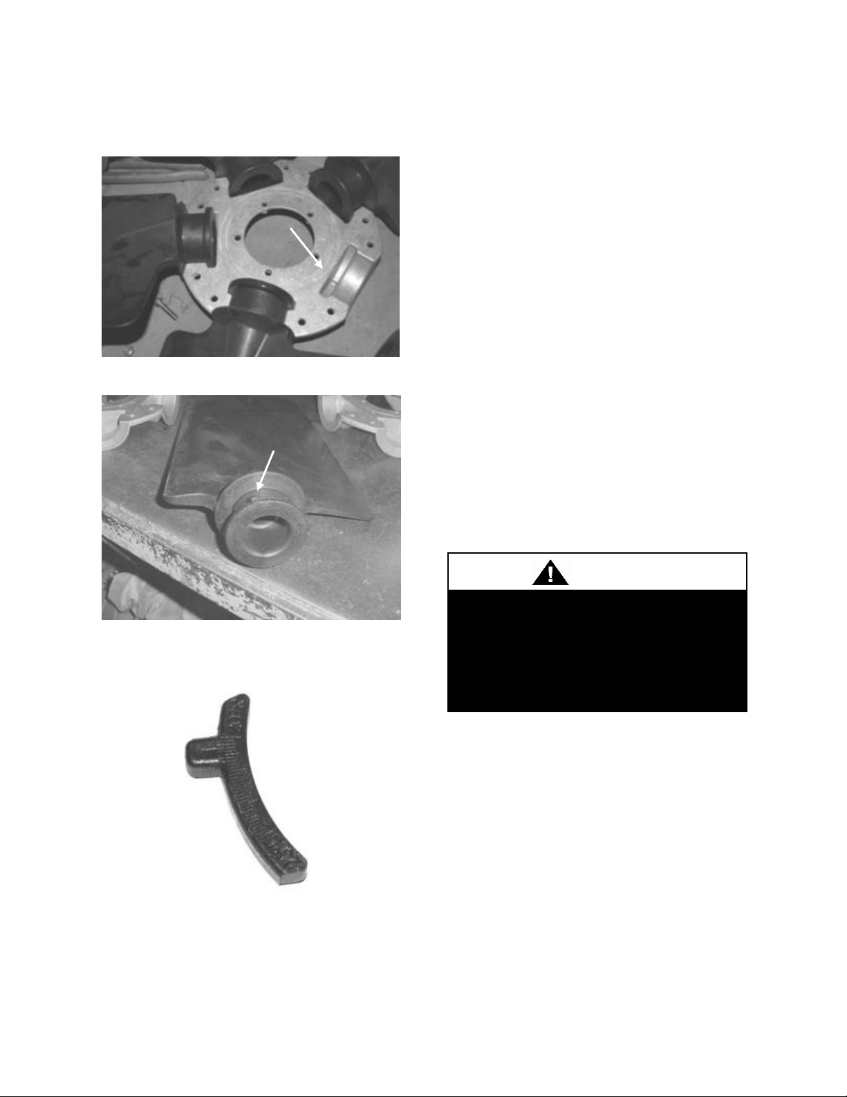
Pin Groove
Pitch Pin
Before completing startup and
leaving the unit a complete operating
cycle should be observed to verify
that all components are functioning
properly.
CAUTION
Step 4: Remove the fan blades and replace
the pitch pins
Figure 39 - Pin Groove Location
Figure 40 - Pitch Pin Location
Figure 41 - Example Pitch Pin
Step 5: Replace the fan blades with the pitch
pin of the blade in the same groove and
reassemble the fan.
Replace the blades and assemble the fan
making sure to place the blades in their
previous blade sockets, to match up the
previous orientation of hub plate casings and
to replace any balancing weights in their
previous locations. Tighten bolts in a cross
pattern to 6.7 ft-lbs. of torque.
Step 6: Install the fan in the unit.
After placing the fan on the shaft, place the
key in the shaft, make sure the screw on the
bushing is aligned over the key and then
tighten the screw to 9 ft-lbs torque.
Filters
Do not operate the unit without filters in
place. Unit should be checked for correct
filter placement during startup. Operation of
the equipment without filters will result in a
clogged evaporator coil.
Adjusting Refrigerant Charge Adjusting the charge of a system in the field must be based on determination of liquid sub-cooling and evaporator superheat. On a system with a TXV liquid sub-cooling is more representative of the charge than evaporator superheat but both measurements must be taken.
75
Page 76

The Clean Air Act of 1990 bans the
intentional venting of refrigerant
(CFC’s and HCFC’s) as of July 1,
1992. Approved methods of recovery,
recycling or reclaiming must be
followed. Fines and/or incarceration
may be levied for non-compliance.
CAUTION
Before Charging
Unit being charged must be at or near full
load conditions before adjusting the charge.
Units equipped with hot gas reheat must be
charged with the hot gas reheat valves
closed while the unit is in cooling mode to
get the proper charge. After charging, unit
should be operated in reheat
(dehumidification) mode to check for
correct operation.
Units equipped with heat pump options
should be charged in heating mode to get the
proper charge. After charging, unit should
be operated in cooling mode to check for
correct charge. Charge may need to be
adjusted for cooling mode. If adjustments
are made in the cooling mode heating mode
must be rerun to verify proper operation.
After adding or removing charge the system
must be allowed to stabilize, typically 10-15
minutes, before making any other
adjustments.
The type of unit and options determine the
ranges for liquid sub-cooling and evaporator
superheat. Refer to the table below when
determining the proper sub-cooling.
Checking Liquid Sub-Cooling
Measure the temperature of the liquid line as
it leaves the condenser coil.
76
Read the gauge pressure at the liquid line
close to the point where the temperature was
taken. You must use liquid line pressure as it
will vary from discharge pressure due to
condenser coil pressure drop.
Convert the pressure obtained to a saturated
temperature using the appropriate refrigerant
temperature-pressure chart.
Subtract the measured liquid line
temperature from the saturated temperature
to determine the liquid sub-cooling.
Compare calculated sub-cooling to the table
below for the appropriate unit type and
options.
Checking Evaporator Superheat
Measure the temperature of the suction line
close to the compressor.
Read gauge pressure at the suction line close
to the compressor.
Convert the pressure obtained to a saturated
temperature using the appropriate refrigerant
temperature-pressure chart.
Subtract the saturated temperature from the
measured suction line temperature to
determine the evaporator superheat.
Compare calculated superheat to the table
below for the appropriate unit type and
options.
Page 77
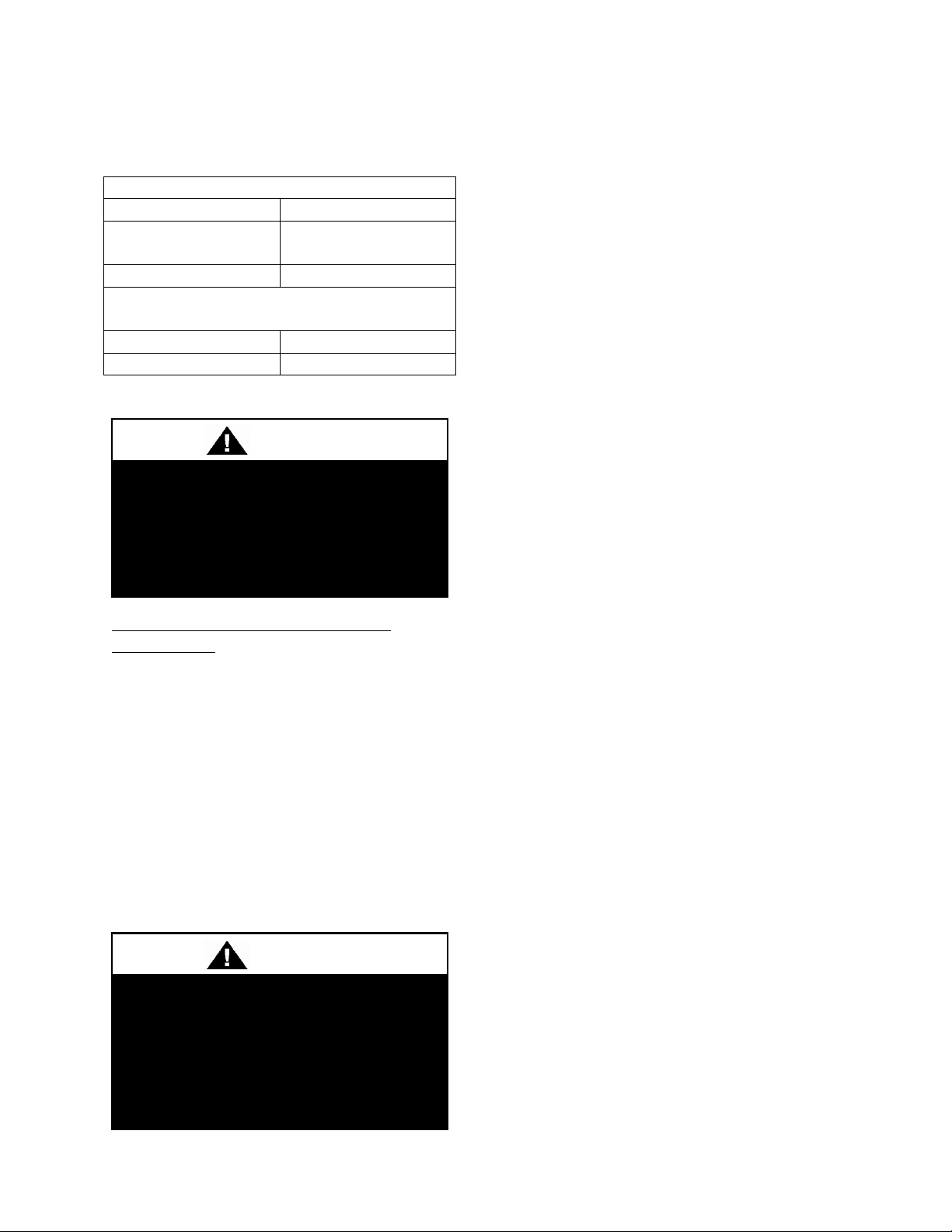
Air-Cooled Cond./Air-Air Heat Pump
Sub-Cooling
12-18°F
Sub-Cooling with
Hot Gas Reheat
15-22°F
Superheat
8-15°F
Water-Cooled Cond./Water Source Heat
Pump
Sub-Cooling
4-8°F
Superheat
8-15°F
DO NOT OVERCHARGE!
Refrigerant overcharging leads to
excess refrigerant in the condenser
coils resulting in elevated compressor
discharge pressure.
CAUTION
Thermal expansion valve must be
adjusted to approximately 8-15°F of
suction superheat. Failure to have
sufficient superheat will damage the
compressor and void the warranty.
CAUTION
Table 25 - Acceptable Refrigeration
Circuit Values
Adjusting Sub-cooling and Superheat Temperatures
The system is overcharged if the sub-cooling
temperature is too high and the evaporator is
fully loaded (low loads on the evaporator
result in increased sub-cooling) and the
evaporator superheat is within the
temperature range as shown in the table
above (high superheat results in increased
sub-cooling).
Correct an overcharged system by reducing
the amount of refrigerant in the system to
lower the sub-cooling.
The system is undercharged if the superheat
is too high and the sub-cooling is too low
Correct an undercharged system by adding
refrigerant to the system to reduce superheat
and raise sub-cooling.
If the sub-cooling is correct and the
superheat is too high, the TXV may need
adjustment to correct the superheat.
77
Page 78

PSIG
PSIG
PSIG
PSIG
PSIG
(F)
R-410A
R-22
(F)
R-410A
R-22
(F)
R-410A
R-22
(F)
R-410A
R-22
(F)
R-410A
R-22
20
78.3
43.1
50
142.2
84.1
80
234.9
143.6
110
364.1
226.4
140
540.1
337.4
21
80.0
44.2
51
144.8
85.7
81
238.6
146.0
111
369.1
229.6
141
547.0
341.6
22
81.8
45.3
52
147.4
87.4
82
242.3
148.4
112
374.2
232.8
142
553.9
345.9
23
83.6
46.5
53
150.1
89.1
83
246.0
150.8
113
379.4
236.1
143
560.9
350.3
24
85.4
47.6
54
152.8
90.8
84
249.8
153.2
114
384.6
239.4
144
567.9
354.6
25
87.2
48.8
55
155.5
92.6
85
253.7
155.7
115
389.9
242.8
145
575.1
359.0
26
89.1
50.0
56
158.2
94.4
86
257.5
158.2
116
395.2
246.1
146
582.3
363.5
27
91.0
51.2
57
161.0
96.1
87
261.4
160.7
117
400.5
249.5
147
589.6
368.0
28
92.9
52.4
58
163.8
98.0
88
265.4
163.2
118
405.9
253.0
148
596.9
372.5
29
94.9
53.7
59
166.7
99.8
89
269.4
165.8
119
411.4
256.5
149
604.4
377.1
30
96.8
55.0
60
169.6
101.6
90
273.5
168.4
120
416.9
260.0
150
611.9
381.7
31
98.8
56.2
61
172.5
103.5
91
277.6
171.0
121
422.5
263.5
32
100.9
57.5
62
175.4
105.4
92
281.7
173.7
122
428.2
267.1
33
102.9
58.8
63
178.4
107.3
93
285.9
176.4
123
433.9
270.7
34
105.0
60.2
64
181.5
109.3
94
290.1
179.1
124
439.6
274.3
35
107.1
61.5
65
184.5
111.2
95
294.4
181.8
125
445.4
278.0
36
109.2
62.9
66
187.6
113.2
96
298.7
184.6
126
451.3
281.7
37
111.4
64.3
67
190.7
115.3
97
303.0
187.4
127
457.3
285.4
38
113.6
65.7
68
193.9
117.3
98
307.5
190.2
128
463.2
289.2
39
115.8
67.1
69
197.1
119.4
99
311.9
193.0
129
469.3
293.0
40
118.1
68.6
70
200.4
121.4
100
316.4
195.9
130
475.4
296.9
41
120.3
70.0
71
203.6
123.5
101
321.0
198.8
131
481.6
300.8
42
122.7
71.5
72
207.0
125.7
102
325.6
201.8
132
487.8
304.7
43
125.0
73.0
73
210.3
127.8
103
330.2
204.7
133
494.1
308.7
44
127.4
74.5
74
213.7
130.0
104
334.9
207.7
134
500.5
312.6
45
129.8
76.1
75
217.1
132.2
105
339.6
210.8
135
506.9
316.7
46
132.2
77.6
76
220.6
134.5
106
344.4
213.8
136
513.4
320.7
47
134.7
79.2
77
224.1
136.7
107
349.3
216.9
137
520.0
324.8
48
137.2
80.8
78
227.7
139.0
108
354.2
220.0
138
526.6
329.0
49
139.7
82.4
79
231.3
141.3
109
359.1
223.2
139
533.3
333.2
Table 26 - R-410A and R-22 Refrigerant Temperature-Pressure Chart
78
Page 79
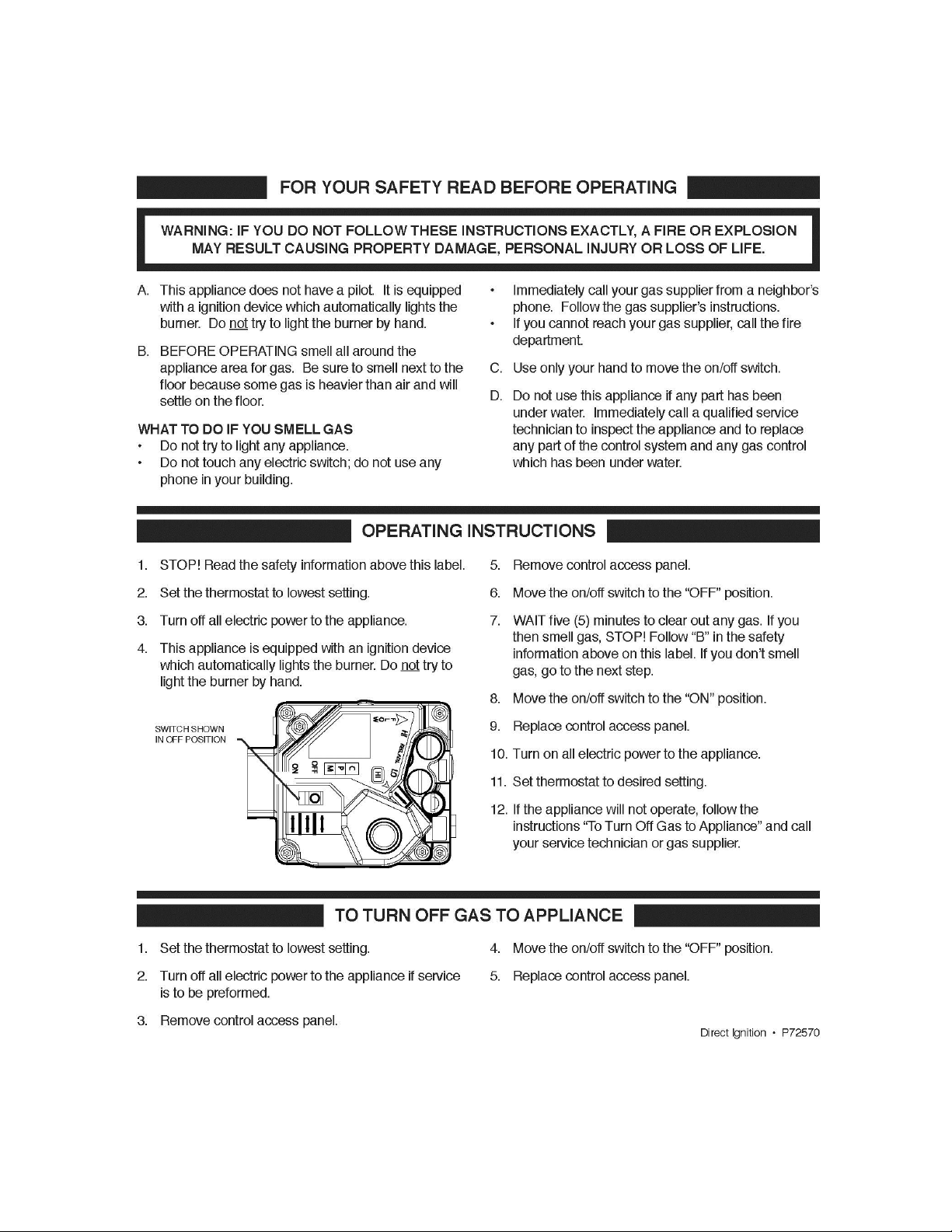
Gas Heater Instructions
Figure 42 - Gas Heater Instructions
79
Page 80

Color
Terminal
Customer
Connection
Option 1
Option 2
Option 3
Option 4
Option 5
Black
0.50
BWS
L1
208-230
VAC
208-230
VAC
208-230
VAC
208-230
VAC
208-230
VAC
Brown
0.50
BWS
L2
208-230
VAC
208-230
VAC
208-230
VAC
208-230
VAC
208-230
VAC
Green
#10
EYELET
Ground
GND
GND
GND
GND
GND
Blue
0.50
BWS
Common
Common
24 VAC
24 VAC
24 VAC
24 VAC
Yellow
0.50
BWS
Signal
PWM
24 VAC
24 VAC
White
0.50
BWS
Signal
24 VAC
24 VAC
Orange
0.50
BWS
Signal
24 VAC
24 VAC
RPM
300-1100
300
500
850
1100
Rotation
CCW
CCW
CCW
CCW
CCW
ECM Toolbox ID
Variable
Speed 4
Speed 3
Speed 2
Speed 1
20% PWM RPM
300
100% PWM RPM
1100
Condenser Fan Electronically Commutated Motor (ECM) Startup
The fan cycling option uses a fan cycle
switch to switch between one of the discrete
speed inputs (see Table 27) on the motor
thus cycling between two preset speeds
based upon discharge pressure of the unit.
By connecting 24VAC to a single or
combination of the yellow, white, or orange
wires, the motor will run at the discrete
speeds in Table 27.
With Customer Provided Unit Controls or
WattMaster Unit Controls the WattMaster
Condenser Head Pressure Module is used
for variable speed control of the motor to
maintain a head pressure. The motor should
be factory wired to the PWM outputs of the
Table 27 - ECM Condenser Fan Cycling Options
WattMaster Condenser Head Pressure
Module. See WattMaster literature for
further information.
(http://www.orioncontrols.com)
With JENEsys Unit Controls the controller
modulates the ECM to maintain head
pressure.
Note
High voltage wires out of the motor:
Black & Brown - 1 Phase Line Voltage
Green - Ground
Low control voltage wires out of the motor:
Blue - Common
Yellow - Variable Speed Control
80
Page 81

VFD Controlled Condenser Fan Startup
With Customer Provided Unit Controls the
VFD’s are factory provided and factory
programmed. VFD’s receives input from
pressure transducers on each refrigerant
circuit and vary the fan speed based on the
pressure inputs to maintain a discharge
(head) pressure. Standard pressure setpoint
is 340 psi for standard air-cooled systems
and 400 psi for modulating hot gas reheat
air-cooled systems.
With WattMaster Unit Controls the
WattMaster Condenser Head Pressure
Module is used to maintain a discharge
pressure. The VFD should be factory wired
to the outputs of the WattMaster Condenser
Head Pressure Module. See WattMaster
literature for additional information.
(http://www.orioncontrols.com).
With JENEsys Unit Controls the controller
directly modulates the VFD to maintain a
discharge pressure.
81
Page 82

COMPRESSOR CYCLING
5 MINUTE MINIMUM OFF TIME
To prevent motor overheating
compressors must cycle off for a
minimum of 5 minutes.
5 MINUTE MINIMUM ON TIME
To maintain the proper oil level
compressors must cycle on for a
minimum of 5 minutes.
The cycle rate must not exceed 6
starts per hour.
WARNING
Operation
Unit operations should be controlled with
thermostat, or unit controller, never at the
main power supply, except for servicing,
emergency, or complete shutdown of the
unit.
Thermostat Operation
Heating
Thermostat system switch - "Heat"
Thermostat fan switch - "Auto" or "On"
Thermostat temperature set to desired point.
Cooling
Thermostat system switch - "Cool"
Thermostat fan switch - "Auto" or "On"
Thermostat temperature set to desired point.
Air Circulation
Thermostat system switch - "Off"
Thermostat fan switch - "Auto" or "On"
No change of the thermostat temperature.
With these settings, the supply blower will
run continuously but the supply air will not
be heated, cooled, or dehumidified.
System Off
Thermostat system switch - "Off"
Thermostat fan switch - "Auto"
No change of the thermostat temperature.
With these settings the system is shut down,
with the exception of control system power.
Night and Weekend Unoccupied Operation
To reduce the operating time of the unit
when the space is unoccupied, such as nights
and weekends, it is recommended that the
temperature setting be raised about 5°F
while unoccupied during the cooling season
and lowered about 10°F during the heating
season.
82
Packaged DX Cooling Operation and Control
When a call for cooling (G and Y1, Y2, etc.)
is made the supply blower motors and
compressors will energize.
Gas Heater Operation
When heat (G and W1, W2, etc.) is called
for the combustion motor starts and the
ignition control is energized. The control
sends 24 VAC to the main gas valve and
high voltage to the igniter. If a burner flame
has been detected within 10 seconds, the
spark is extinguished and the flame
continues. If a flame has not been detected
after 10 seconds, the gas valve closes, the
spark ceases and the induced draft blower
continues to purge the heat exchanger. After
45 seconds of purge, the ignition system will
attempt to light the burners again. Should no
flame be detected after 3 tries, the ignition
control will lock out the system. Power to
the ignition control must be cycled to reset
the heater control.
On a fault the gas train is shut down by a
main limit located in the heat exchanger area
or by an auxiliary limit mounted in the
supply fan compartment.
Page 83

Electric Heating Operation
When a call for heating (G and W1, W2,
etc.) is made the supply blower motors and
electric resistance heaters will energize.
Heating is accomplished by passing
electrical current through a specified amount
of resistance heaters which will produce the
required heat.
On a fault condition the main limit located
in the supply air or the auxiliary limit
located downstream the supply blower will
remove power from all contactors.
Steam or Hot Water Preheating and Heating Operation
Valve control for steam and hot water
heating coils are by others. Heating is
accomplished by passing steam or hot water
through the steam or hot water coil
assembly.
Modulating Electric Preheat
Electric preheat is used to temper the
incoming outside air to the unit based on an
enable control signal and outside air
conditions. Electric preheat has a maximum
operation outside air temperature of 60°F
and a maximum preheat discharge air
temperature of 80°F.
Chilled Water or Non-Compressorized DX Cooling Operation
Controls for chilled water cooling coils and
non-compressorized DX coil are by others.
83
Page 84

Once a year, before the unit is in
operation for the heating season, a
qualified service technician should
inspect all flue product carrying areas
of the furnace and main burners for
continued safe operation.
WARNING
LEAK CHECK GAS PIPE
The gas pipe in the unit should be
checked for leaks before startup.
Leak checking is the responsibility of
the installing contractor. All
connections should be checked for
leaks annually after installation.
Failure to leak check could result in
fire, explosion, or other hazardous
situations.
DANGER
Maintenance
(See back of the manual for maintenance
log)
At least once each year, a trained, qualified
service technician should check out the unit.
Fans, evaporator coils, and filters should be
inspected at least monthly.
Gas Heating
Make sure all gas supply lines have been
purged of air before turning on the electrical
power switch. Turn the gas valve to the on
position (see startup instructions). Turn the
main electrical power on and set the controls
to the heating mode of operation.
The combustion ventilation motor should
operate. The control will automatically
supply energy to the igniter and the gas
valve after the heating call is made.
84
The flame sensing probe detects the
presence of the flame. Should no flame be
detected in 10 seconds, the ignition system
will recycle. If no flame is detected after 3
tries, ignition system will lockout.
Remove the call for heating. The main gas
valves should be extinguished.
The supply fans are controlled by the
ignition system. In the fan “Auto” mode the
fan comes on 45 seconds after the flame is
proved and goes off 120 seconds after the
heating call is removed.
Furnace combustion ventilation air and flue
openings should be checked annually for
debris and obstructions. If vent extensions
are used they must meet category III
requirements.
This appliance contains a wire screen at the
vent outlet. Each heating season, prior to
placing the appliance in heat mode
maintenance check that no debris or foreign
matter has accumulated in the vent outlet. A
good practice is to check for debris each
time the air filters are changed.
In the event the vent outlet becomes blocked
do not attempt to start the appliance in heat
mode until the entire vent opening is
cleared.
In the event the unit shut down because the
vent was blocked a qualified technician or
service agency should monitor the unit prior
to re-starting.
The gas burner and heat exchanger should
never require cleaning. If cleaning is
necessary, this indicates faulty operation of
the unit. Cleaning should only be done by a
qualified service agency and only after
consultation with an AAON service
representative.
Page 85

Electric shock hazard. Shut off all
electrical power to the unit to avoid
shock hazard or injury from rotating
parts.
WARNING
LEAK CHECK GAS PIPE
The gas pipe in the unit should be
checked for leaks before startup.
Leak checking is the responsibility of
the installing contractor. All
connections should be checked for
leaks annually after installation.
Failure to leak check could result in
fire, explosion, or other hazardous
situations.
DANGER
If induced draft blower/motor assembly has
to be replaced, care must be taken to provide
an airtight seal between the blower housing
and the burner box.
Gas Heat Exchanger Removal
Removal
Disconnect all wiring on the heat exchanger.
Disconnect flex gas lines and pull out of the
way.
Remove screws around the perimeter of the
heat exchanger face plate that connect it to
the unit. Only the outermost screws should
be removed.
Pull the heat exchanger straight back and out
of the unit. It may be necessary to remove
some of the control door jambs.
Reinstallation
Ensure that the neoprene gasket is installed
around the perimeter of the heat exchanger.
Insert heat exchanger into opening so that
the back of the main plate is against the unit
bulkhead.
Figure 43 - Gas Heat Exchanger
Attach the heat exchanger to the bulkhead
using the holes around the perimeter.
Connect flex gas lines to the piping on the
heat exchanger. If flexible gas piping in the
unit must be replaced connectors cannot be
reused, only new connectors must be used.
Connect wiring per the wiring diagram on
the controls compartment door.
Purge gas lines to the gas valves at the unit.
DX Cooling
Set unit controls to cooling mode of
operation with supply fans on. Check the fan
for correct operating direction, amperage
and voltage. Check compressor operation,
rotation, amperage and voltage to the unit
nameplate (check the amperage on the load
side of the compressor contactor).
85
Page 86

Electric shock hazard. Shut off all
electrical power to the unit to avoid
shock hazard or injury from rotating
parts.
WARNING
Improper installation, adjustment,
alteration, service, or maintenance
can cause property damage,
personal injury, or loss of life. Startup
and service must be performed by a
Factory Trained Service Technician.
WARNING
Condenser Fans (6-25 and 30 ton)
Condenser fans and motors can be removed
and reinstalled as individual assemblies.
Removal
Take off the fan grill by removing the
screws that attach it to the orifice.
The condenser fan motor wires can then be
accessed and disconnected.
Remove the screws that attach the orifice to
the condenser assembly. The screws are
located on the top of the orifice around the
perimeter, and in some cases, through the
side of the condenser assembly into the
orifice.
With the wires disconnected and the screws
removed, the fan, motor and orifice
assembly can be lifted off the unit.
86
Figure 44 - Removal of a Condenser Fan
Assembly
Reinstallation
Set the condenser fan, motor and orifice
assembly back into the condenser assembly
with the motor wires on the side closest to
the control panel.
Attach the orifice to the condenser assembly
using all of the points where screws were
removed.
Reconnect the fan motor wires.
Attach the fan grill at all of the points where
screws were removed.
Condensate Drain Pans
Drain pans will have moisture present and
require periodic cleaning to prevent
microbial growth. Cleaning of the drain pans
will also prevent any possible plugging of
the drain lines and overflow of the pan itself.
Cleaning of the drain pans and inside of the
unit should be done only by qualified
service technician.
Page 87
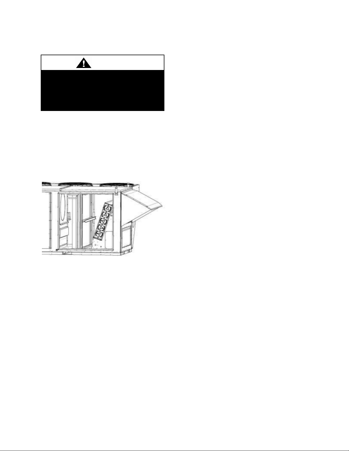
Electric shock hazard. Shut off all
electrical power to the unit to avoid
shock hazard or injury from rotating
parts.
WARNING
Evaporator Coil (6-25 and 30 ton)
Removal
Evacuate refrigerant from the systems.
Remove the TXV bulbs from the suction
lines. Disconnect the suction and liquid line
copper connections to the evaporator coil.
Figure 45 - Evaporator Coil Access
Remove the screws attaching the filter rack
to the evaporator coil blank-off panels at the
door opening and along the top of the coil.
Remove the screws attaching the filter rack
to the back wall. Angle filter rack away
from coil so it fits through the door opening.
It may be necessary to remove economizer
damper assembly.
Remove screws attaching access side, back,
and top blank-off panels to the evaporator
coil and the unit.
Angle the coil so that it fits through the door
opening.
Remove the evaporator coil.
Reinstallation
Install the coil in the unit drain pan. There
should be about a 1/4” gap between the
upstream side of the coil and the back of the
drain pan.
Secure the coil to the back wall of the unit
with the blank-off panel. Attach the top and
access side blank-off panels to the coil.
Attach the filter rack to the back, top, and
access side coil blank-off panels upstream of
the coil. Reinstall economizer damper
assembly if necessary.
Connect the suction and liquid copper
connections to the evaporator coil. Reinstall
the TXV bulbs on the suction lines.
Evacuate the refrigerant systems. Weigh in
the nameplate refrigerant charge.
See Adjusting Refrigerant Charge section to
check for proper sub-cooling and superheat
of the refrigerant systems.
Brazed Plate Heat Exchanger Cleaning
Because of a normally high degree of
turbulence in brazed plate heat exchangers,
for many applications the heat exchanger
channels are self cleaning. For applications
that are not self cleaning (i.e. hard water at
high temperatures, etc.) or applications
where additional cleaning is desired, it is
possible to clean the brazed plate heat
exchanger by circulating a cleaning liquid.
Use a tank with weak acid, 5% phosphoric
acid (H3PO4) or, if the exchanger is
frequently cleaned, 5% oxalic acid
(H2C2O4). Pump the cleaning liquid
through the exchanger. For optimum
cleaning, the cleaning solution flow rate
should be a minimum of 1.5 times the
87
Page 88

Electric shock hazard. Shut off all
electrical power to the unit to avoid
shock hazard or injury from rotating
parts.
WARNING
Harsh chemicals, household bleach,
or acid cleaners should not be used
to clean outdoor or indoor e-coated
coils. These cleaners can be very
difficult to rinse out of the coil and
can accelerate corrosion and attack
the e-coating. If there is dirt below the
surface of the coil, use the
recommended coil cleaners.
High velocity water from a pressure
washer or compressed air should
only be used at a very low pressure
to prevent fin and/or coil damages.
The force of the water or air jet may
bend the fin edges and increase
airside pressure drop. Reduced unit
performance or nuisance unit
shutdowns may occur.
CAUTION
CAUTION
normal flow rate, preferably in a back-flush
mode. After cleaning, the heat exchanger
must be rinsed with clean water. A solution
of 1-2% sodium hydroxide (NaOH) or
sodium bicarbonate (NaHCO) before the last
rinse ensures that all acid is neutralized.
E-Coated Coil Cleaning
Documented routine cleaning of e-coated
coils is required to maintain coating
warranty coverage for fin and tube and
microchannel coils.
Surface loaded fibers or dirt should be
removed prior to water rinse to prevent
restriction of airflow. If unable to back wash
the side of the coil opposite of the coils
entering air side, then surface loaded fibers
or dirt should be removed with a vacuum
cleaner. If a vacuum cleaner is not available,
a soft non-metallic bristle brush may be
used. In either case, the tool should be
applied in the direction of the fins. Coil
surfaces can be easily damaged (fin edges
bent over) if the tool is applied across the
fins.
Use of a water stream, such as a garden
hose, against a surface loaded coil will drive
the fibers and dirt into the coil. This will
make cleaning efforts more difficult. Surface
loaded fibers must be completely removed
prior to using low velocity clean water rinse.
A monthly clean water rinse is
recommended for coils that are applied in
coastal or industrial environments to help to
remove chlorides, dirt, and debris. It is very
88
important when rinsing, that water
temperature is less than 130°F and pressure
is than 900 psig to avoid damaging the fin
edges. An elevated water temperature (not to
exceed 130°F) will reduce surface tension,
increasing the ability to remove chlorides
and dirt.
Quarterly cleaning is essential to extend
the life of an e-coated coil and is required
to maintain coating warranty coverage.
Coil cleaning shall be part of the unit’s
regularly scheduled maintenance
procedures. Failure to clean an e-coated coil
will void the warranty and may result in
reduced efficiency and durability.
For routine quarterly cleaning, first clean the
coil with the below approved coil
cleaner. After cleaning the coils with the
approved cleaning agent, use the approved
Page 89

Detergents or coil cleaners are not
recommended with microchannel
condenser coils. Use pressurized
clean water, with pressure not to
exceed 140 psi. Nozzle should be 6”
and 80° to 90° from coil face. Failure
to do so could result in coil damage.
CAUTION
chloride remover to remove soluble salts and
revitalize the unit.
Recommended Coil Cleaner
The following cleaning agent, assuming it is
used in accordance with the manufacturer’s
directions on the container for proper mixing
and cleaning, has been approved for use on
e-coated coils to remove mold, mildew,
dust, soot, greasy residue, lint, and other
particulate:
Enviro-Coil Concentrate, Part Number HEC01.
Recommended Chloride Remover
CHLOR*RID DTS™ should be used to
remove soluble salts from the e-coated coil,
but the directions must be followed closely.
This product is not intended for use as a
degreaser. Any grease or oil film should first
be removed with the approved cleaning
agent.
Remove Barrier - Soluble salts adhere
themselves to the substrate. For the effective
use of this product, the product must be able
to come in contact with the salts. These salts
may be beneath any soils, grease or dirt;
therefore, these barriers must be removed
prior to application of this product. As in all
surface preparation, the best work yields the
best results.
Apply CHLOR*RID DTS - Apply directly
onto the substrate. Sufficient product must
be applied uniformly across the substrate to
thoroughly wet out surface, with no areas
missed. This may be accomplished by use of
a pump-up sprayer or conventional spray
gun. The method does not matter, as long as
the entire area to be cleaned is wetted. After
the substrate has been thoroughly wetted,
the salts will be soluble and is now only
necessary to rinse them off.
Rinse - It is highly recommended that a hose
be used, as a pressure washer will damage
the fins. The water to be used for the rinse is
recommended to be of potable quality,
though a lesser quality of water may be used
if a small amount of CHLOR*RID DTS is
added. Check with CHLOR*RID
International, Inc. for recommendations on
lesser quality rinse water.
Microchannel Coil Cleaning Documented routine cleaning of microchannel coils with factory provided ecoating is required to maintain coating warranty coverage. See E-Coated Coil Cleaning section.
Air-cooled heat exchangers may include
microchannel coils. Only clean water is
recommended for cleaning microchannel
coils. The water pressure used to clean
should not exceed 140 psi, from no closer
than 3 inches from the coils, and with the
water aimed perpendicular to the coils.
Only clean water is recommended for
cleaning microchannel coils. However, if
solutions are mandatory to clean the unit, a
cleaning solution with a pH between 5 and 9
that does not contain chlorides, sulfates,
copper, iron, nickel, or titanium is required.
Field applied coil coatings are not
recommended with microchannels.
89
Page 90
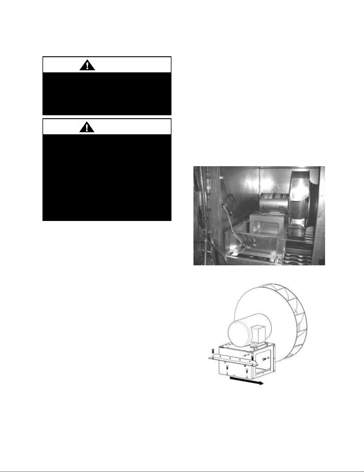
Electric shock hazard. Shut off all
electrical power to the unit to avoid
shock hazard or injury from rotating
parts.
WARNING
Blower wheels and bands must be
inspected for excessive dust build up
periodically and cleaned if required.
Excessive dust build up on blower
wheels may cause an unbalanced
state; leading to vibration and/or
component failure. Damages due to
excessive dust build up will not be
covered under factory warranty.
CAUTION
Supply Fans
Lubrication
All original fan motors and bearings are
furnished with factory lubrication. Some
applications will require that bearings be relubricated periodically. The schedule will
depend on the operating duty, temperature
variations or other severe atmospheric
conditions.
Bearings should be re-lubricated when at
normal operating temperatures, but not
running. Rotate the fan shaft by hand and
add only enough grease to purge the seals.
DO NOT OVERLUBRICATE.
Recommended greases are:
SHELL OIL - DOLIUM R
CHEVRON OIL - SRI No. 2
TEXACO INC. - PREMIUM RB
Removal (6-25 and 30 tons)
Remove fan access panel. Panel is attached
with eight 3/8” bolts.
90
Remove the wire connections from
Auxiliary Limit Switch (if applicable) which
is mounted in the brace at the fan opening.
Remove the brace located at the fan
opening.
Remove the six bolts that connect the motor
mount to the blower frame. Two bolts are on
the angle on the back of the motor mount
box, two are on the bottom inside the motor
mount box and two are on the inside front of
the motor mount box.
Figure 46 - 9-25 and 30 ton Supply Fan
Figure 47 - Bolts which Connect Motor
Mount to Blower Fan
Slide the motor mount back away from the
air inlet, so that the blower wheel is clear of
Page 91
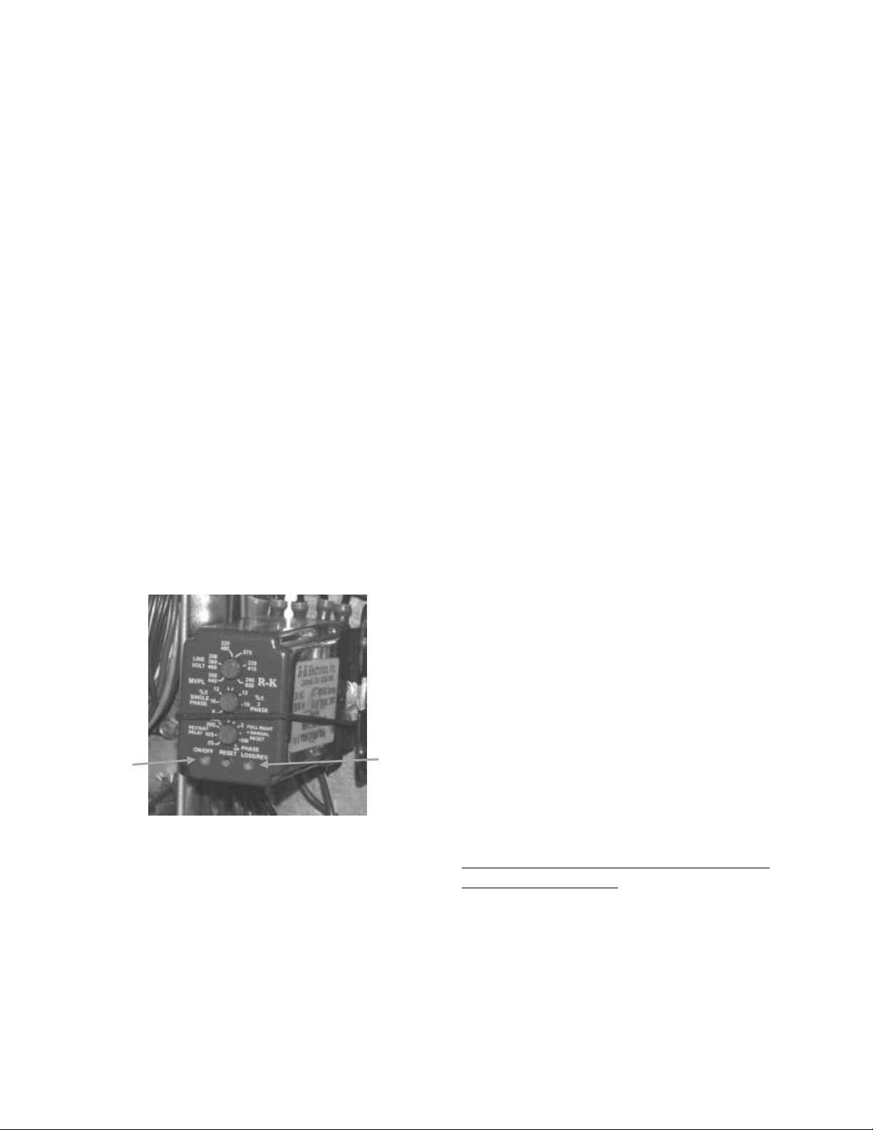
Phase
Loss/Rev.
LED
On/Off
LED
the inlet. A screw driver or crowbar can be
used to help accomplish this. Use the pry
slots on the back side of the motor mount.
Pull the motor mount to the edge of the
blower frame at the opening.
Remove the motor mount with the motor
and blower wheel attached. Large motors
will require more than one person.
Care must be taken not to damage the
compressors or refrigerant lines when
removing the motor and fan assembly.
Phase and Brownout Protection
Voltage monitor should be wired according
to unit specific wiring diagram include in
the control compartment.
Before applying power to the unit the
voltage monitor should be set up. The three
knobs on the front of the monitor should be
adjusted.
Figure 48 - Voltage Monitor
Adjust the top knob labeled LINE VOLT to
the operating voltage. This should be the
operating voltage for the equipment and the
measured voltage on the single or three
phase lines.
Adjust the knob labeled %± to either
SINGLE PHASE on the left side of the dial
or 3 PHASE on the right side of the dial.
After selecting single or three phase set the
knob to the percentage of Over or Under
voltage desired. A typical over and under
voltage percentage is 10%.
Adjust the bottom knob labeled RESTART
DELAY. For automatic restart after
recovery of voltage select from 2 seconds up
to 5 minutes. After recovery of line voltage
this is how long the monitor will wait before
energizing the output relay. For manual reset
adjust the knob fully clockwise to MR. After
recovery of line voltage the MANUAL
RESET button located between the 2 LEDs
must be pressed.
Now that the settings have been made, you
can apply the supply and line voltages to the
monitor. The monitor will only operate
when the supply voltage is available.
On power up, with the line voltage and the
supply voltage applied, the monitor takes 3
to 10 seconds to evaluate the line voltage,
compare that voltage to the knob settings
and then energize if all parameters are
satisfied or will remain off if any operating
parameter is incorrect.
All of the knob adjustments are adjustable
after power up, except the voltage range will
not change and going from single or three
phase to the other will not change (i.e.
within 440 to 480 VAC, but not to 208 or
230 VAC).
LED Codes
Powering up with voltage present which
matches knob settings:
1. On/Off LED = Alternating Green/Red
Phase Loss LED = Out
2. On/Off LED = Out
Phase Loss LED = Alt. G/R
3. On/Off LED = Alt. G/R
Phase Loss LED = Out
91
Page 92

24COM
Module Common
24VAC
Module Power
C1 & C2
Demand Input – & +
P1
Pressure Common
P2
Pressure Input
P3
Pressure Power 5VDC
P4
Pressure Shield
P5 & P6
Pressure Output – & +
T1 & T2
Discharge Temperature Sensor
A1 & A2
Alarm Relay Out
M1 & M2
Contractor
L1
Control Voltage N
L2
Control Voltage L
U1 & U2
Digital Unloader Solenoid
V1 & V2
Vapor Injection Solenoid
To avoid damaging the Compressor
Controller do not connect wires to
terminals C3, C4, T3, T4, T5, or T6.
WARNING
4. On/Off LED = Alt. G/R Flashing
Phase Loss LED = Green
5. On/Off LED = Green
Phase Loss LED = Green
Powering up with no voltage present:
1. On/Off LED = Alternating Green/Red
Phase Loss LED = Out
Going into trip condition after operating
conditions were good:
1. On/Off LED = Green
Phase Loss LED = Green
2. On/Off LED = Green Flashing
Phase Loss LED = Red
3. On/Off LED = Red
Phase Loss LED = Red
Going to good condition from trip condition
- automatic reset:
1. On/Off LED = Red
Phase Loss LED = Red
2. On/Off LED = Alt. G/R Flashing
Phase Loss LED = Green
3. On/Off LED = Green
Phase Loss LED = Green
Going to good condition from trip condition
- manual reset:
1. On/Off LED = Red
Phase Loss LED = Red
2. On/Off LED = Alt. G/R Flashing
Phase Loss LED = Green
3. Manual Reset button is pressed
4. On/Off LED = Green
Phase Loss LED = Green
Variable Capacity Compressor Controller
Units with variable capacity scroll
compressors may include the following
compressor controller. The following is an
explanation of the terminals and
troubleshooting alert flash codes of the
controller. For more information on the
compressor controller, see Emerson Climate
Bulletin AE8-1328.
Figure 49 - Variable Capacity Compressor
Controller
Low Voltage Terminals
High Voltage Terminals
The compressor controller modulates the
compressor unloader solenoid in an on/off
92
Page 93
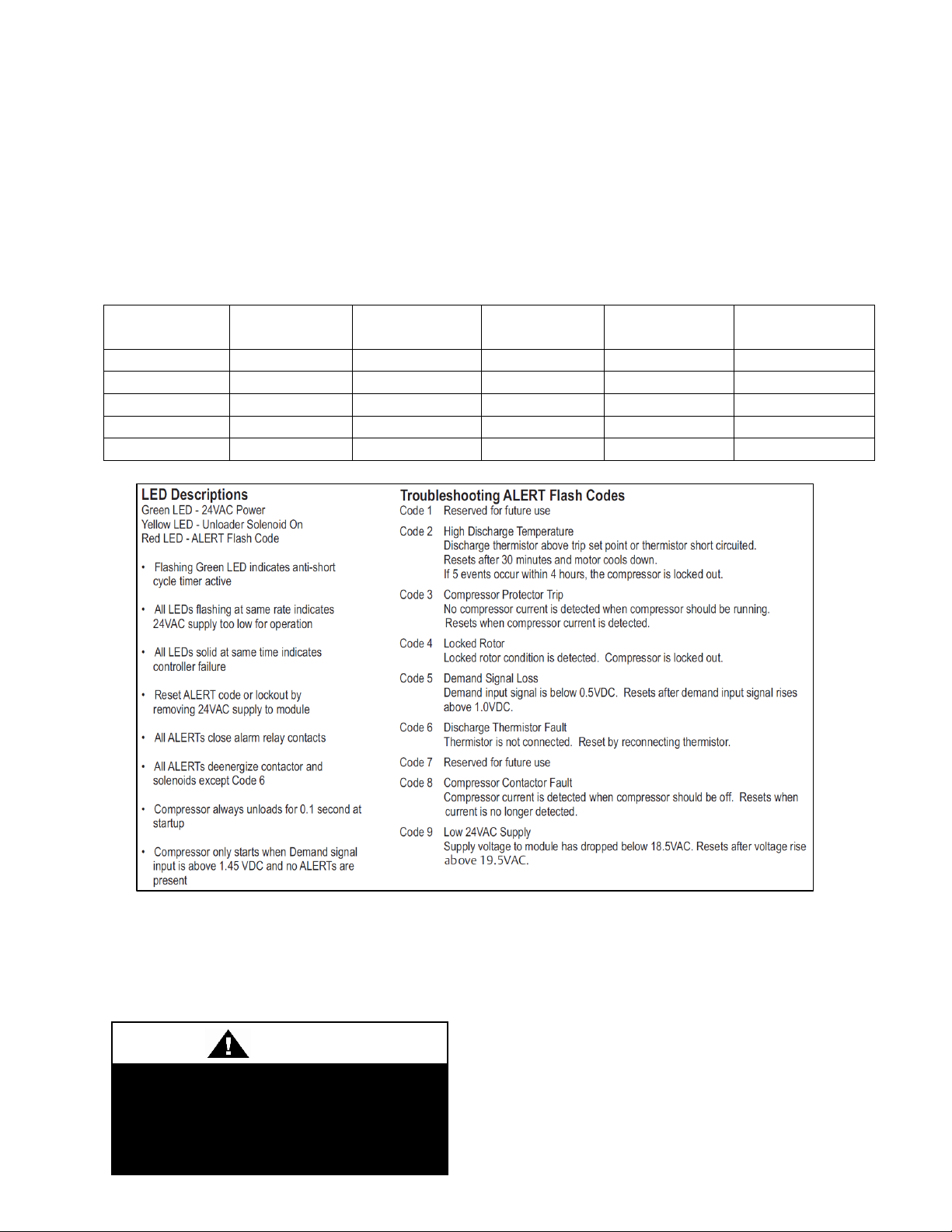
Demand
Signal (VDC)
Loaded %
Unloaded %
Time Loaded
Time
Unloaded
% Compressor
Capacity
1.00
Off
Off
Off
Off
0%
1.44
10%
90%
1.5 sec
13.5 sec
10%
3.00
50%
50%
7.5 sec
7.5 sec
50%
4.20
80%
20%
12 sec
3 sec
80%
5.00
100%
0%
15 sec
0 sec
100%
Electric shock hazard. Shut off all
electrical power to the unit to avoid
shock hazard or injury from rotating
parts.
WARNING
pattern according to the capacity demand
signal of the system. The following table
shows the linear relationship between the
demand signal and compressor capacity
modulation. The compressor controller
protects the compressor against high
discharge temperature. Refer to Appendix B
Table 28 - Demand Signal vs. Compressor Capacity Modulation
for the relationship between thermistor
temperature readings and resistance values.
Figure 50 - Compressor Controller Flash Code Details
Filter Replacement
Monthly air filter inspection is required to
maintain optimum unit efficiency.
It is strongly recommended that filter media
be replaced monthly. Filters are located
upstream of the evaporator coil in the filter
and economizer section. Open access door
and pull filters straight out to inspect all of
the filters. Replace filters with the size
indicated on each filter or as shown in the
tables below. Arrow on the replacement
93
Page 94
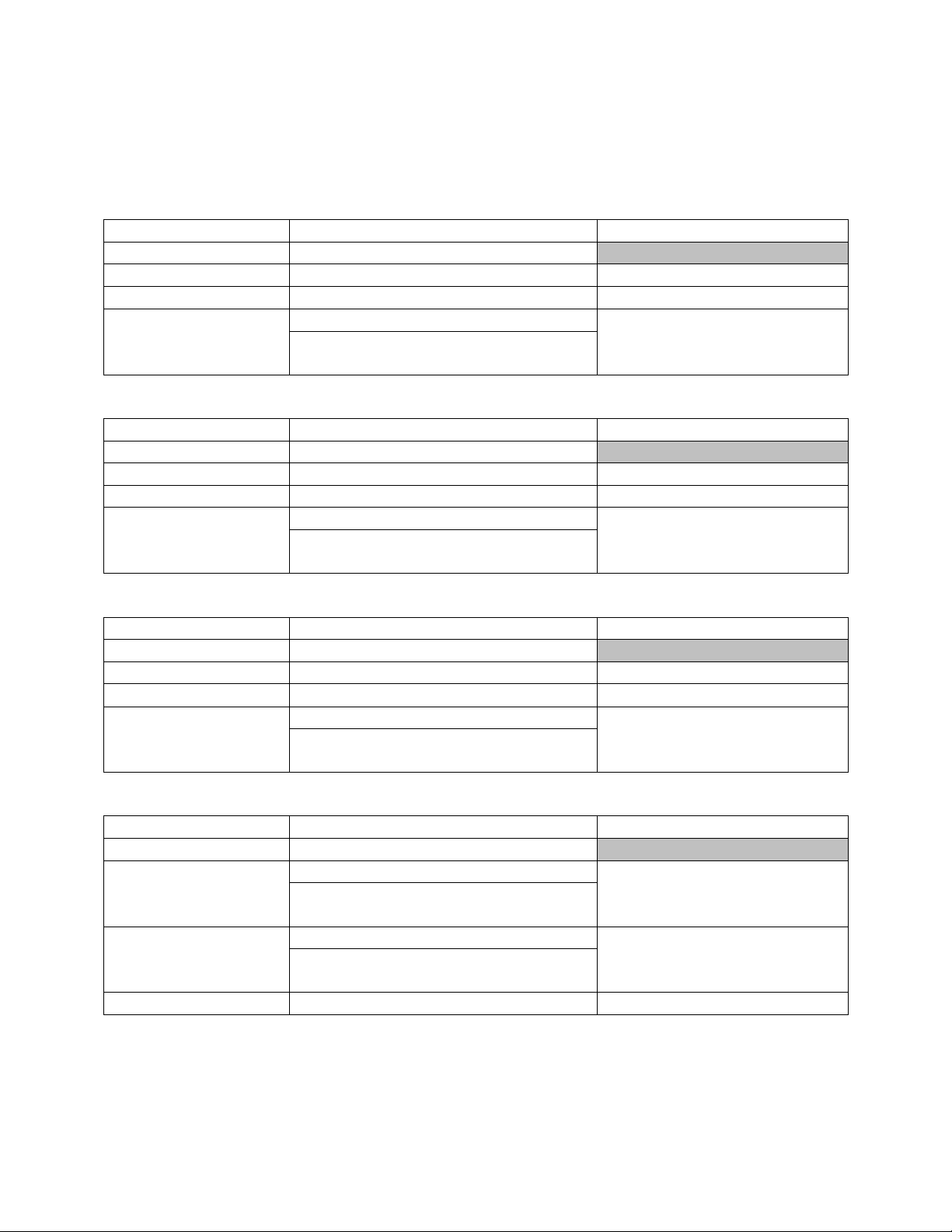
Feature 6A
Quantity / Size
Type
0
No Pre Filters
A
4 / 16” x 20” x 2”
Pleated, 30% Eff, MERV 8
B
2 / 16” x 20” x 1”
Metal Mesh, Outside Air
C
2 / 40” x 16” x 5/16”
Lint Screen
with RAB, Feature A2 = Q, R
2 / 40” x 16” x 5/16”
Feature 6A
Quantity / Size
Type
0
No Pre Filters
A
4 / 20” x 25” x 2”
Pleated, 30% Eff, MERV 8
B
2 / 20” x 25” x 1”
Metal Mesh, Outside Air
C
2 / 49” x 20” x 5/16”
Lint Screen
with RAB, Feature A2 = Q, R
3 / 47” x 12” x 5/16”
Feature 6A
Quantity / Size
Type
0
No Pre Filters
A
6 / 20” x 25” x 2”
Pleated, 30% Eff, MERV 8
B
3 / 20” x 25” x 1”
Metal Mesh, Outside Air
C
2 / 55” x 25” x 5/16”
Lint Screen
with RAB, Feature A2 = Q, R
3 / 55” x 16” x 5/16”
Feature 6A
Quantity / Size
Type
0
No Pre Filters
A
8 / 24” x 24” x 2”
Pleated, 30% Eff, MERV 8
with RAB, Feature A2 = Q, R
16 / 12” x 24” x 2”
B
6 / 16” x 25” x 1”
Metal Mesh, Outside Air
with PE or PR, Feature 1A = B, C
4 / 16” x 25” x 1”
C
8 / 24” x 24” x 5/16”
Lint Screen
filters must point towards the blower. (RAB
= Return Air Bypass, PE = Power Exhaust
and PR = Power Return)
Table 29 - 6-8 and 10 ton Pre Filters
Table 30 - 9 and 11-15 ton Pre Filters
Table 31 - 16-25 and 30 ton Pre Filters
Table 32 - 26, 31, and 40 ton Pre Filters
94
Page 95
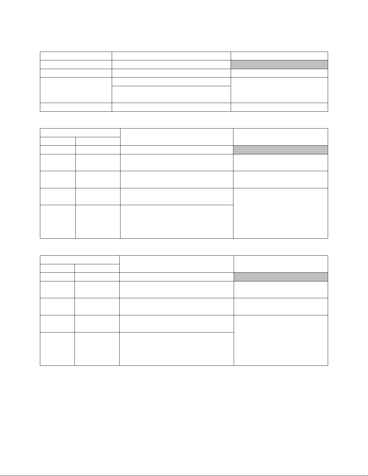
Feature 6A
Quantity / Size
Type
0
No Pre Filters
A
24 / 12” x 24” x 2”
Pleated, 30% Eff, MERV 8
B
6 / 16” x 25” x 1”
Metal Mesh, Outside Air
with PE or PR, Feature 1A = B, C
4 / 16” x 25” x 1”
C
12 / 47” x 12” x 5/16”
Lint Screen
Feature
Quantity / Size
Type
6A
6B
0
A,B,C,F,G,H
No Pre Filters
A
A,B,C,F,G,H
15 / 20” x 24” x 2” &
5 / 16” x 20” x 2”
Pleated, 30% Eff, MERV 8
B
A,B,C,F,G,H
56 / 20” x 20” x 1”
Metal Mesh, Outside Air
C
A,C
8 / 40” x 18” &
8 / 20” x 18”
Lint Screen
C
B,F,G,H
1 / 60” x 16” &
3 / 60” x 24” &
1 / 40” x 16” &
3 / 40” x 24”
Feature
Quantity / Size
Type
6A
6B
0
A,B,C,F,G,H
No Pre Filters
A
A,B,C,F,G,H
21 / 20” x 24” x 2” &
7 / 16” x 20” x 2”
Pleated, 30% Eff, MERV 8
B
A,B,C,F,G,H
56 / 20” x 20” x 1”
Metal Mesh, Outside Air
C
A,C
11 / 20” x 18” &
12 / 40” x 18”
Lint Screen
C
B,F,G,H
2 / 40” x 16” &
6 / 40” x 24” &
1 / 60” x 16” &
3 / 60” x 24”
Table 33 - 50, 60, and 70 ton Pre Filters
Table 34 - 55, 65, and 75 ton Pre Filters
Table 35 - 90-140 ton Pre Filters
95
Page 96

Feature 6B
Quantity / Size
Type
0
4 / 16” x 20” x 2”
Pleated, 30% Eff, MERV 8
with RAB, Feature A2 = Q, R
2 / 20” x 20” x 2” and
1/12” x 24” x 2”
B
4 / 16” x 20” x 4”
Pleated, 30% Eff, MERV 8
with RAB, Feature A2 = Q, R
2 / 20” x 20” x 4” and
1/12” x 24” x 4”
C
4 / 16” x 20” x 2”
Permanent Filter Frame -
Replaceable Media
with RAB, Feature A2 = Q, R
2 / 20” x 20” x 2” and
1/12” x 24” x 2”
F
4 / 16” x 20” x 4”
Pleated, 65% Eff, MERV 11
G
Pleated, 85% Eff, MERV 13
H
Pleated, 95% Eff, MERV 14
Feature 6B
Quantity / Size
Type
0
4 / 20” x 25” x 2”
Fiberglass Throwaway,
25% Eff, MERV 4
with RAB, Feature A2 = Q, R
6 / 12” x 24” x 2”
A
4 / 20” x 25” x 2”
Pleated, 30% Eff, MERV 8
with RAB, Feature A2 = Q, R
6 / 12” x 24” x 2”
B
4 / 20” x 25” x 4”
Pleated, 30% Eff, MERV 8
with RAB, Feature A2 = Q, R
6 / 12” x 24” x 4”
C
4 / 20” x 25” x 2”
Permanent Filter Frame -
Replaceable Media
with RAB, Feature A2 = Q, R
6 / 12” x 24” x 2”
F
4 / 20” x 25” x 4”
Pleated, 65% Eff, MERV 11
G
Pleated, 85% Eff, MERV 13
H
Pleated, 95% Eff, MERV 14
Table 36 - 6-8 and 10 ton Unit Filters
Table 37 - 9 and 11 ton Unit Filters
96
Page 97

Feature 6B
Quantity / Size
Type
0
4 / 20” x 25” x 2”
Pleated, 30% Eff, MERV 8
with RAB, Feature A2 = Q, R
6 / 12” x 24” x 2”
B
4 / 20” x 25” x 4”
Pleated, 30% Eff, MERV 8
with RAB, Feature A2 = Q, R
6 / 12” x 24” x 4”
C
4 / 20” x 25” x 2”
Permanent Filter Frame -
Replaceable Media
with RAB, Feature A2 = Q, R
6 / 12” x 24” x 2”
F
4 / 20” x 25” x 4”
Pleated, 65% Eff, MERV 11
G
Pleated, 85% Eff, MERV 13
H
Pleated, 95% Eff, MERV 14
Feature 6B
Quantity / Size
Type
0
6 / 20” x 25” x 2”
Pleated, 30% Eff, MERV 8
with RAB, Feature A2 = Q, R
9 / 16” x 20” x 2”
B
6 / 20” x 25” x 4”
Pleated, 30% Eff, MERV 8
with RAB, Feature A2 = Q, R
9 / 16” x 20” x 4”
C
6 / 20” x 25” x 2”
Permanent Filter Frame -
Replaceable Media
with RAB, Feature A2 = Q, R
9 / 16” x 20” x 2”
F
6 / 20” x 25” x 4”
Pleated, 65% Eff, MERV 11
G
Pleated, 85% Eff, MERV 13
H
Pleated, 95% Eff, MERV 14
Table 38 - 13 and 15 ton Unit Filters
Table 39 - 16-25 and 30 ton Unit Filters
97
Page 98

Feature 6B
Quantity / Size
Type
0
8 / 24” x 24” x 2”
Pleated, 30% Eff, MERV 8
with RAB, Feature A2 = Q, R
16 / 12” x 24” x 2”
B
8 / 24” x 24” x 4”
Pleated, 30% Eff, MERV 8
with RAB, Feature A2 = Q, R
16 / 12” x 24” x 4”
C
8 / 24” x 24” x 2”
Permanent Filter Frame -
Replaceable Media
with RAB, Feature A2 = Q, R
16 / 12” x 24” x 2”
F
8 / 24” x 24” x 4”
Pleated, 65% Eff, MERV 11
with RAB, Feature A2 = Q, R
16 / 12” x 24” x 4”
G
8 / 24” x 24” x 4”
Pleated, 85% Eff, MERV 13
with RAB, Feature A2 = Q, R
16 / 12” x 24” x 4”
H
8 / 24” x 24” x 4”
Pleated, 95% Eff, MERV 14
with RAB, Feature A2 = Q, R
16 / 12” x 24” x 4”
Feature 6B
Quantity / Size
Type
0
24 / 12” x 24” x 2”
Pleated, 30% Eff, MERV 8
B
24 / 12” x 24” x 4”
Pleated, 30% Eff, MERV 8
C
24 / 12” x 24” x 2”
Permanent Filter Frame -
Replaceable Media
F
24 / 12” x 24” x 4”
Pleated, 65% Eff, MERV 11
G
Pleated, 85% Eff, MERV 13
H
Pleated, 95% Eff, MERV 14
Feature 6B
Quantity / Size
Type
0
25 / 18” x 20” x 2”
Pleated, 30% Eff, MERV 8
B
15 / 20” x 24” x 4” &
5 / 16” x 20” x 4”
Pleated, 30% Eff, MERV 8
C
25 / 18” x 20” x 2”
Permanent Filter Frame -
Replaceable Media
F
15 / 20” x 24” x 4” &
5 / 16” x 20” x 4”
Pleated, 65% Eff, MERV 11
G
Pleated, 85% Eff, MERV 13
H
Pleated, 95% Eff, MERV 14
Table 40 - 26, 31, and 40 ton Unit Filters
Table 41 - 50, 60, and 70 ton Unit Filters
Table 42 - 55, 65, and 75 ton Unit Filters
98
Page 99

Feature 6B
Quantity / Size
Type
0
35 / 18” x 20” x 2”
Pleated, 30% Eff, MERV 8
B
21 / 20” x 24” x 4” &
7 / 16” x 20” x 4”
Pleated, 30% Eff, MERV 8
C
35 / 18” x 20” x 2”
Permanent Filter Frame -
Replaceable Media
F
21 / 20” x 24” x 4” &
7 / 16” x 20” x 4”
Pleated, 65% Eff, MERV 11
G
Pleated, 85% Eff, MERV 13
H
Pleated, 95% Eff, MERV 14
Feature 1A
Quantity / Size
Type
F, G, H, J, Q, R, S, T
1 / 25” x 16” x 4”
Pleated, 30% Eff, MERV 8
With Energy Recovery Wheel Exhaust
Air Filters, Feature 6A - D, F, G
OA - 1 / 25” x 16” x 2”
EA - 1 / 25” x 16” x 2”
Feature 1A
Quantity / Size
Type
F, G, H, J, Q, R, S, T
2 / 16” x 20” x 4”
Pleated, 30% Eff, MERV 8
With Energy Recovery Wheel Exhaust
Air Filters, Feature 6A - D, F, G
OA - 2 / 16” x 20” x 2”
EA - 2 / 16” x 20” x 2”
Feature 1A
Quantity / Size
Type
F, G, H, J, Q, R, S, T,
U, V, W, Y, Z, 1, 2, 3
3 / 20” x 25” x 4”
Pleated, 30% Eff, MERV 8
With Energy Recovery Wheel Exhaust
Air Filters, Feature 6A - D, F, G
OA - 3 / 20” x 25” x 2”
EA - 6 / 14” x 20” x 2”
Table 43 - 90-140 ton Unit Filters
Table 44 - 6-8 and 10 ton Energy Recovery Wheel Filters
Table 45 - 9 and 11-15 ton Energy Recovery Wheel Filters
Table 46 - 16-25 and 30 ton Energy Recovery Wheel Filters
99
Page 100

Feature 1A
Quantity / Size
Type
F, G, H, J, Q, R, S, T,
U, V, W, Y, Z, 1, 2, 3
4 / 24” x 24” x 4”
Pleated, 30% Eff, MERV 8
With Energy Recovery Wheel Exhaust
Air Filters, Feature 6A - D, F, G
OA - 4 / 24” x 24” x 2”
EA - 8 / 16” x 20” x 2”
4
3 / 24” x 24” x 4”
With Energy Recovery Wheel Exhaust
Air Filters, Feature 6A - D, F, G
OA - 3 / 24” x 24” x 2”
EA - 6 / 16” x 20” x 2”
Feature 1A
Quantity / Size
Type
F, G, H, J, Q, R, S, T
10 / 24” x 24” x 2”
Pleated, 30% Eff, MERV 8
With Energy Recovery Wheel Exhaust
Air Filters, Feature 6A - D, G
OA - 10 / 24” x 24” x 2”
EA - 14 / 25” x 16” x 2”
U, V, W, Y, Z, 1, 2, 3
10 / 24” x 20” x 2”
With Energy Recovery Wheel Exhaust
Air Filters, Feature 6A - D, G
OA - 14 / 20” x 24” x 2”
EA - 14 / 25” x 16” x 2”
Feature
Quantity / Size
Type
14A
14B
A, B, C,
D
A, B, C,
D, E, F
6 / 16” x 25” x 1”
Metal Mesh, Outside Air
with PE or PR, Feature 1A = B, C
4 / 16” x 25” x 1”
Table 47 - 26, 31-50, 60, and 70 ton Energy Recovery Wheel Filters
Table 48 - 55, 65, and 75-140 ton Energy Recovery Wheel Filters
Table 49 - 26, 31-50, 60, and 70 ton Energy Recovery Wheel Filters
100
 Loading...