

Page 1
RL SERIES
G
G
Packaged Rooftop Units & Outdoor Air Handling Units
Installation, Operation,
& Maintenance
Failure to follow safety warnings
exactly could result in serious
injury, death or property damage.
Be sure to read and understand
the installation, operation and
service instructions in this manual.
Improper installation, adjustment,
alteration, service or maintenance
can cause serious injury, death or
property damage.
A copy of this IOM should be kept
with the unit.
WARNIN
FIRE OR EXPLOSION HAZARD
o Do not store gasoline or other flammable
o WHAT TO DO IF YOU SMELL GAS
o Startup and service must be performed by a
WARNIN
vapors and liquids in the vicinity of this or any
other appliance
Do not try to light any appliance.
Do not touch any electrical switch; do not
use any phone in your building.
Leave the building immediately.
Immediately call your gas supplier from a
phone remote from the building. Follow the
gas supplier’s instructions.
If you cannot reach your gas supplier, call
the fire department.
Factory Trained Service Technician.
Page 2

Page 3

Table of Contents
Safety .............................................................................................................................................. 8
RL Series Feature String Nomenclature ....................................................................................... 13
General Information ...................................................................................................................... 22
Certification of Gas Heat Models ............................................................................................. 22
Certification of Steam or Hot Water Heat Models ................................................................... 22
Certification of Electric Heat Models ....................................................................................... 22
Certification of Cooling Models ............................................................................................... 22
Codes and Ordinances .............................................................................................................. 22
Receiving Unit .......................................................................................................................... 23
Storage ...................................................................................................................................... 23
Packaged Direct Expansion (DX) Units ................................................................................... 23
Gas or Electric Heating ............................................................................................................. 24
Wiring Diagrams ....................................................................................................................... 24
Condensate Drain Pan ............................................................................................................... 24
Installation..................................................................................................................................... 25
Locating Units ........................................................................................................................... 25
Curb Installation ....................................................................................................................... 25
Duct Connection ....................................................................................................................... 26
Lifting the Unit ......................................................................................................................... 27
Reassembling Split Units .......................................................................................................... 29
Electrical Connection of Split Units ......................................................................................... 30
Outside Air Rain Hood ............................................................................................................. 30
End Flashing Installation .......................................................................................................... 30
Vestibule Exhaust Fan .............................................................................................................. 31
Electrical ................................................................................................................................... 31
Gas Heating ............................................................................................................................... 33
Piping Sizing Example .......................................................................................................... 33
Inlet and Manifold Pressures ................................................................................................ 33
Gas Pressure Regulator & Overpressure Protection Device ............................................... 34
Piping Supports ..................................................................................................................... 34
Additional Gas Piping Considerations ................................................................................. 34
Leak Testing .......................................................................................................................... 34
Rain Hoods ............................................................................................................................ 35
Condensate Drain Piping .......................................................................................................... 36
Draw-Through Coils ................................................................................................................. 37
Hot Water/Steam Heating and Chilled Water Cooling Coils ................................................... 38
Evaporative-Cooled Condenser ................................................................................................ 38
Energy Recovery Units ............................................................................................................. 40
Startup ........................................................................................................................................... 47
Supply, Return, and Exhaust Backward Curved Fans .............................................................. 47
Airflow Adjustment ................................................................................................................ 47
Power Return and Exhaust Axial Flow Fans ............................................................................ 48
Adjustable Fan Cycling Switch Procedure ............................................................................... 51
RL Prop Assembly .................................................................................................................... 53
Spring Isolator Adjustment ....................................................................................................... 53
3
Page 4

Back Draft Damper Setup ......................................................................................................... 54
Filters ........................................................................................................................................ 55
Cartridge Filter Installation ....................................................................................................... 55
Adjusting Refrigerant Charge ................................................................................................... 55
Before Charging .................................................................................................................... 55
Checking Liquid Sub-Cooling ............................................................................................... 56
Checking Evaporator Superheat ........................................................................................... 56
Adjusting Sub-cooling and Superheat Temperatures ........................................................... 57
Refrigerant Filter Driers ............................................................................................................ 57
Indirect Gas Heat Startup .......................................................................................................... 59
Access Doors ............................................................................................................................ 60
Operation....................................................................................................................................... 61
Indirect Gas Heater Operation .................................................................................................. 61
Electric Heating Operation ....................................................................................................... 61
Steam or Hot Water Preheating and Heating Operation ........................................................... 61
Packaged DX Cooling Operation ............................................................................................. 61
Chilled Water or Non-Compressorized DX Cooling Operation ............................................... 61
Maintenance .................................................................................................................................. 62
Gas Heating ............................................................................................................................... 62
Direct Fired Gas Heat ............................................................................................................... 62
Ignition Sequence of Operations: ............................................................................................. 63
Safeties: ..................................................................................................................................... 63
Initial Start-up Procedure: ......................................................................................................... 64
First Firing or Restart after Extended Shut-down: .................................................................... 64
General Maintenance Instructions: ........................................................................................... 64
Inspection and Maintenance of Gas Ports: ............................................................................... 65
DX Cooling ............................................................................................................................... 65
Condensate Drain Pans ............................................................................................................. 66
Supply Fans ............................................................................................................................... 66
Lubrication ............................................................................................................................ 66
Phase and Brownout Protection Module .................................................................................. 66
Filter Replacement .................................................................................................................... 69
Evaporative-Cooled Condenser ................................................................................................ 69
Severe Service ........................................................................................................................... 69
Safety ........................................................................................................................................ 69
Performance .............................................................................................................................. 70
Warranties ................................................................................................................................. 70
Condenser Tube Inspection ...................................................................................................... 70
Freeze Protection ...................................................................................................................... 70
Recirculating Water System ..................................................................................................... 70
Pre Start-Up .............................................................................................................................. 70
Cleanliness ................................................................................................................................ 71
Storage ...................................................................................................................................... 71
Pump Operation ........................................................................................................................ 71
Running ..................................................................................................................................... 71
Condenser Fan Motors .............................................................................................................. 71
4
Page 5

Water Makeup Valve ................................................................................................................ 71
Water Treatment System .......................................................................................................... 72
Sequence of Operations ............................................................................................................ 73
Pump Maintenance ................................................................................................................... 73
Fan Motor Maintenance ............................................................................................................ 74
Access Doors ............................................................................................................................ 74
Bearings - Lubrication .............................................................................................................. 74
Recommended Monthly Inspection .......................................................................................... 74
Mist Eliminators ....................................................................................................................... 74
Air Inlet ..................................................................................................................................... 74
Stainless Steel Base Pan ........................................................................................................... 74
Propeller Fans and Motors ........................................................................................................ 74
Recommended Annual Inspection ............................................................................................ 74
Cleaning .................................................................................................................................... 74
Water Quality ............................................................................................................................ 75
Mechanical Cleaning ................................................................................................................ 76
Air-Cooled Condenser .............................................................................................................. 76
E-Coated Coil Cleaning ............................................................................................................ 76
Replacement Parts ......................................................................................................................... 89
Warranty, Service and Parts Department ...................................................................................... 89
RL Series Startup Form ................................................................................................................ 91
Maintenance Log .......................................................................................................................... 96
Literature Change History............................................................................................................. 97
R10091 · Rev. B · 160425
5
Page 6

Index of Tables and Figures
Tables
Table 1 - Unit Clearances ........................................................................................................................... 25
Table 2 - Mounting Dimensions ................................................................................................................. 27
Table 3 - Gas Piping Connections............................................................................................................... 33
Table 4 - Natural Gas Maximum Piping Capacities (ft
Table 5 - Piping Support Intervals .............................................................................................................. 34
Table 6 - Draw-Through Drain Trap Dimensions....................................................................................... 37
Table 7 - Blow-Through Drain Trap Dimensions ....................................................................................... 38
Table 8 - Plenum Fan Set Screw Specifications ......................................................................................... 48
Table 9 - Return/Exhaust Fan Pin Location in the Bushing Mount ............................................................ 50
Table 10 - Return/Exhaust Fan Pin Location in the Grooves ..................................................................... 50
Table 11 - Prop Assembly Bushing Torque Specifications ........................................................................ 53
Table 12 - Acceptable Sub-Cooling and Superheat Temperatures ............................................................. 57
Table 13 - Filter Drier Maximum Pressure Drop ........................................................................................ 57
Table 14 - R-410A Refrigerant Temperature-Pressure Chart ..................................................................... 58
Table 15 - Recirculating Water Quality Guidelines .................................................................................... 75
Table 16 - RL-045, RL-060, and RL-070 Standard Filters ......................................................................... 78
Table 17 - RL-045, RL-060, and RL-070 Standard Filters ......................................................................... 78
Table 18 - RL-075, RL-090, and RL-095 Standard Filters ......................................................................... 78
Table 19 - RL-075, RL-090, and RL-095 Standard Filters ......................................................................... 79
Table 20 - RL-100, RL-110, RL-120, RL-125, and RL-135 Standard Filters ............................................ 79
Table 21 - RL-100, RL-110, RL-120, RL-125, and RL-135 Standard Filters ............................................ 79
Table 22 - RL-134, RL-150, RL-155, and RL-170 Standard Filters .......................................................... 79
Table 23 - RL-134, RL-150, RL-155, and RL-170 Standard Filters .......................................................... 79
Table 24 - RL-180, RL-181, RL-190, RL-210, RL-230, and RL-240 Standard Filters .............................. 80
Table 25 - RL-180, RL-181, RL-190, RL-210, RL-230, and RL-240 Standard Filters .............................. 80
Table 26 - RL-045 to RL-125 and RL-135 High Efficiency Cartridge Filters ........................................... 80
Table 27 - RL-045 to RL-125 and RL-135 High Efficiency Cartridge Filters ........................................... 81
Table 28 - RL-045 to RL-125 and RL-135 High Efficiency Bag Filters .................................................... 82
Table 29 - RL-045 to RL-125 and RL-135 High Efficiency Bag Filters .................................................... 82
Table 30 - RL-134 and RL-150 to RL-240 High Efficiency Cartridge Filters ........................................... 83
Table 31 - RL-134 and RL-150 to RL-240 High Efficiency Cartridge Filters ........................................... 84
Table 32 - RL-134 and RL-150 to RL-240 High Efficiency Bag Filters .................................................... 85
Table 33 - RL-134 and RL-150 to RL-240 High Efficiency Bag Filters .................................................... 86
Table 34 - RL-045 to RL-125 and RL-135 High Efficiency Cartridge Filters ........................................... 87
Table 35 - RL-045 to RL-125 and RL-135 High Efficiency Bag Filters .................................................... 87
Table 36 - RL-134 and RL-150 to RL-240 High Efficiency Cartridge Filters ........................................... 88
Table 37 - RL-134 and RL-150 to RL-240 High Efficiency Bag Filters .................................................... 88
Table 38 - RL-045 to RL-125 and RL-135 Energy Recovery Wheel Filters .............................................. 89
Table 39 - RL-134 and RL-150 to RL-240 Energy Recovery Wheel Filters .............................................. 89
3
/hr) ........................................................................ 33
6
Page 7

Figures
Figure 1 - RL Series Unit Orientation ......................................................................................................... 25
Figure 2 - Curb Mounting ........................................................................................................................... 26
Figure 3 - Curb Detail ................................................................................................................................. 26
Figure 4 - Curb Mounting with Dimensions ............................................................................................... 27
Figure 5 - Steel Mounting Rail with Dimensions ....................................................................................... 27
Figure 6 - Marked Lifting Points ................................................................................................................ 27
Figure 7 - Unit Base and Sides.................................................................................................................... 29
Figure 8 - Unit Roof Flange Splice Detail .................................................................................................. 29
Figure 9 - Air Hood Shown in the Open Position ....................................................................................... 30
Figure 10 - Factory Supplied End Flashings ............................................................................................... 31
Figure 11 - Vestibule Exhaust Fan .............................................................................................................. 31
Figure 12 - Terminal Block ......................................................................................................................... 32
Figure 13 - Gas Heater Rain Hood .............................................................................................................. 35
Figure 14 - Gas Heater Rain Hood Screws ................................................................................................. 36
Figure 15 - Draw-Through Drain Trap ....................................................................................................... 37
Figure 16 - Blow-Through Drain Trap ....................................................................................................... 37
Figure 17 - Evaporative-Cooled Cond. Section, Including Field Water Connections and Base Cutout ..... 39
Figure 18 - Air Volume Band ..................................................................................................................... 47
Figure 19 - Air Volume Band Tab Locations ............................................................................................. 47
Figure 20 - Securing Air Volume Band Ends ............................................................................................. 48
Figure 21 - Plenum Fan Gap Tolerances .................................................................................................... 48
Figure 22 - Fan with the HUB on the top and RET on the bottom. ............................................................ 49
Figure 23 - Fan Bushing Mount Location ................................................................................................... 49
Figure 24 - RET shown with pin in groove 4 ............................................................................................. 49
Figure 25 - HUB and RET .......................................................................................................................... 49
Figure 26 - Rear Isolator Detail .................................................................................................................. 54
Figure 27 - Fan Assembly Detail ................................................................................................................ 54
Figure 28 - Blower Assembly ..................................................................................................................... 54
Figure 29 - Closed Back Draft Damper ...................................................................................................... 55
Figure 30 - Open Back Draft Damper ......................................................................................................... 55
Figure 31 - Top Clip and Side Spring Fastener Securing Filters in Place .................................................. 55
Figure 32 - Replaceable Core Filter/Drier .................................................................................................. 57
Figure 33 - Lockable Door Handles ............................................................................................................ 60
Figure 34 - Typical Factory Mutual (FM) Gas Piping Schematic for a Direct Fired Heater ...................... 63
Figure 35 - Removing Piping Scale with Pin Vise ..................................................................................... 65
Figure 36 - Proper Unit Location ................................................................................................................ 69
Figure 37 - Improper Unit Locations .......................................................................................................... 70
Figure 38 - Water Makeup Valve ............................................................................................................... 72
7
Page 8
Safety
CAUTIO
G
G
NOTE - Notes are intended to clarify the unit installation, operation and maintenance.
CAUTION - Caution statements are given to prevent actions that may result in
equipment damage, property damage, or personal injury.
WARNING - Warning statements are given to prevent actions that could result in
equipment damage, property damage, personal injury or death.
DANGER - Danger statements are given to prevent actions that will result in equipment
damage, property damage, severe personal injury or death.
Attention should be paid to the following statements:
ELECTRIC SHOCK, FIRE OR
EXPLOSION HAZARD
Failure to follow safety warnings
exactly could result in dangerous
operation, serious injury, death or
property damage.
Improper servicing could result in
dangerous operation, serious injury,
death, or property damage.
Before servicing, disconnect all
When servicing controls, label all
Verify proper operation after
electrical power to the furnace.
More than one disconnect may be
provided.
wires prior to disconnecting.
Reconnect wires correctly.
servicing. Secure all doors with
key-lock or nut and bolt.
WARNING
WHAT TO DO IF YOU SMELL GAS
Do not try to turn on unit.
Shut off main gas supply.
Do not touch any electric switch.
Do not use any phone in the
Never test for gas leaks with an
Use a gas detection soap solution
Electric shock hazard. Before
Electric shock hazard. Shut off all
servicing, shut off all electrical power
electrical power to the unit to avoid
to the unit, including remote
shock hazard or injury from rotating
disconnects, to avoid shock hazard
parts.
or injury from rotating parts. Follow
proper Lockout-Tagout procedures.
building.
open flame.
and check all gas connections
and shut off valves.
WARNIN
WARNIN
N
8
Page 9
G
G
CAUTIO
FIRE, EXPLOSION OR CARBON
MONOXIDE POISONING HAZARD
Failure to replace proper controls
could result in fire, explosion or
carbon monoxide poisoning. Failure
to follow safety warnings exactly
could result in serious injury, death or
property damage. Do not store or use
gasoline or other flammable vapors
and liquids in the vicinity of this
appliance.
WARNING
During installation, testing, servicing,
and troubleshooting of the equipment
it may be necessary to work with live
electrical components. Only a
qualified licensed electrician or
individual properly trained in handling
live electrical components shall
perform these tasks.
Standard NFPA-70E, an OSHA
regulation requiring an Arc Flash
Boundary to be field established and
marked for identification of where
appropriate Personal Protective
Equipment (PPE) be worn, should be
followed.
WARNING
Unit contains fans with moving parts
that can cause serious injury. Do not
open door containing fans until the
power to the unit has been
disconnected and fan wheel has
WARNING
ROTATING COMPONENTS
stopped rotating.
All field installed wiring must be
completed by qualified personnel.
Field installed wiring must comply
with NEC/CEC, local and state
electrical code requirements. Failure
to follow code requirements could
result in serious injury or death.
Provide proper unit ground in
accordance with these code
requirements.
WARNIN
GROUNDING REQUIRED
VARIABLE FREQUENCY DRIVES
Do not leave VFDs unattended in
hand mode or manual bypass.
Damage to personnel or equipment
can occur if left unattended. When in
hand mode or manual bypass mode
VFDs will not respond to controls or
alarms.
WARNIN
Electric motor over-current protection
and overload protection may be a
function of the Variable Frequency
Drive to which the motors are wired.
Never defeat the VFD motor overload
feature. The overload ampere setting
must not exceed 115% of the electric
motors FLA rating as shown on the
motor nameplate.
N
9
Page 10
CAUTIO
CAUTIO
G
G
CAUTIO
G
To prevent injury or death lifting
equipment capacity shall exceed unit
weight by an adequate safety factor.
Always test-lift unit not more than 24
inches high to verify proper center of
gravity lift point to avoid unit damage,
injury or death.
WARNING
UNIT HANDLING
Failure to properly drain and vent
coils when not in use during freezing
temperature may result in coil and
equipment damage.
N
Rotation must be checked on all
MOTORS AND COMPRESSORS of
3 phase units at startup by a qualified
service technician. Scroll
compressors are directional and can
be damaged if rotated in the wrong
direction. Compressor rotation must
be checked using suction and
discharge gauges. Fan motor rotation
should be checked for proper
operation. Alterations should only be
made at the unit power connection
N
Do not use oxygen, acetylene or air
in place of refrigerant and dry
nitrogen for leak testing. A violent
explosion may result causing injury or
death.
WARNING
Prior to connection of condensing
water supply, verify water pressure is
less than maximum pressure shown
on unit nameplate. To prevent injury
or death due to instantaneous
release of high pressure water, relief
valves should be field supplied on
system water piping.
WARNIN
WATER PRESSURE
Always use a pressure regulator,
valves and gauges to control
incoming pressures when pressure
testing a system. Excessive pressure
may cause line ruptures, equipment
damage or an explosion which may
result in injury or death.
WARNIN
To prevent damage to the unit, do not
use acidic chemical coil cleaners. Do
not use alkaline chemical coil
cleaners with a pH value greater than
8.5, after mixing, without first using
an aluminum corrosion inhibitor in the
cleaning solution.
N
Some chemical coil cleaning
compounds are caustic or toxic. Use
these substances only in accordance
with the manufacturer’s usage
instructions. Failure to follow
instructions may result in equipment
WARNIN
damage, injury or death.
10
Page 11
CAUTIO
CAUTIO
CAUTIO
G
G
G
Do not clean DX refrigerant coils with
hot water or steam. The use of hot
water or steam on refrigerant coils
will cause high pressure inside the
coil tubing and damage to the coil.
Door compartments containing
hazardous voltage or rotating parts
are equipped with door latches to
allow locks. Door latch are shipped
with nut and bolts requiring tooled
access. If you do not replace the
shipping hardware with a pad lock
always re-install the nut & bolt after
closing the door.
Cleaning the cooling tower or
condenser water loop with harsh
chemicals such as hydrochloric acid
(muriatic acid), chlorine or other
chlorides, can damage the
refrigerant-to-water heat exchanger.
Care should be taken to avoid
allowing chemicals to enter the
refrigerant-to-water heat exchanger.
See Appendix A - Heat Exchanger
Corrosion Resistance for more
information.
Failure of the condenser as a result
of chemical corrosion is excluded
from coverage under AAON Inc.
warranties and the heat exchanger
manufacturer’s warranties.
OPEN LOOP APPLICATIONS
WARNING
N
N
N
Failure of the condenser due to
freezing will allow water to enter the
refrigerant circuit and will cause
extensive damage to the refrigerant
circuit components. Any damage to
the equipment as a result of water
freezing in the condenser is excluded
from coverage under AAON
warranties and the heat exchanger
manufacturer warranties.
To prevent motor overheating
compressors must cycle off for a
minimum of 5 minutes.
To maintain the proper oil level
compressors must cycle on for a
minimum of 5 minutes.
The cycle rate must not exceed 6
startsper hour.
1. Startup and service must be performed
by a Factory Trained Service
Technician.
2. Use only with type of the gas approved
for the furnace. Refer to the furnace
rating plate.
3. The unit is for outdoor use only. See
General Information section for more
information.
WATER FREEZING
COMPRESSOR CYCLING
5 MINUTE MINIMUM OFF TIME
5 MINUTE MINIMUM ON TIME
WARNIN
WARNIN
WARNIN
11
Page 12

4. Provide adequate combustion ventilation
air to the furnace. If a vent duct
extension is used, a class III approved
vent is required. See the Locating Units
and Gas Heating sections of the
Installation section of the manual.
5. Always install and operate furnace
within the intended temperature rise
range and duct system external static
pressure (ESP) as specified on the unit
nameplate.
6. The supply and return air ducts shall be
derived from the same space. It is
recommended ducts be provided with
access panels to allow inspection for
duct tightness. When a down flow duct
is used with electric heat, the exhaust
duct should be an L shaped duct.
7. Clean furnace, duct, and components
upon completion of the construction
setup. Verify furnace operating
conditions including input rate,
temperature rise, and ESP.
8. Every unit has a unique equipment
nameplate with electrical, operational,
and unit clearance specifications.
Always refer to the unit nameplate for
specific ratings unique to the model you
have purchased.
9. READ THE ENTIRE INSTALLATION,
OPERATION, AND MAINTENANCE
MANUAL. OTHER IMPORTANT
SAFETY PRECAUTIONS ARE
PROVIDED THROUGHOUT THIS
MANUAL.
10. Keep this manual and all literature
safeguarded near or on the unit.
12
Page 13
RL Series Feature String Nomenclature
R
E
A
Model Options Unit Feature Options
GEN
SIZE
VLT
CONFIGA1A2A3A4B1B2B3
L–100–3–0–B
BASE MODEL
SERIES AND GENERATION
RL
UNIT SIZE
045 = 45 Nominal Tons
060 = 60 Nominal Tons
070 = 70 Nominal Tons
075 = 75 Nominal Tons
090 = 90 Nominal Tons
095 = 95 Nominal Tons
100 = 100 Nominal Tons
110 = 110 Nominal Tons
120 = 120 Nominal Tons
125 = 125 Nominal Tons
134 = 134 Nominal Tons
135 = 135 Nominal Tons
150 = 150 Nominal Tons
155 = 155 Nominal Tons
170 = 170 Nominal Tons
180 = 180 Nominal Tons
181 = 181 Nominal Tons
190 = 190 Nominal Tons
210 = 210 Nominal Tons
230 = 230 Nominal Tons
240 = 240 Nominal Tons
VOLTAGE
2 = 230V/3Φ/60Hz
3 = 460V/3Φ/60Hz
4 = 575V/3Φ/60Hz
8 = 208V/3Φ/60Hz
INTERIOR PROTECTION
0 = Standard
A = Interior Corrosion Protection
06–3 5 2 : BEBE–D0 0–QFY–P0
:
1A1B1C1D23
4
5A5B5C6A6B6C78910111213
0DBB000–00–0BB00AB0B
–
14A14B1516171819202122
Model Option A: COOLING
A1: COOLING STYLE
B = Blow-Through, R-410A, Dual Circuited
C = Draw-Through, R-410A, Dual Circuited
D = Blow Through - R-134a Variable Capacity OilFree Magnetic Bearing Centrifugal Compressors
E = Draw Through - R-134a Variable Capacity OilFree Magnetic Bearing Centrifugal Compressors
F = Blow-Through AHU w/ Vestibule
G = Draw-Through AHU w/ Vestibule
H = Blow-Through AHU w/ Front Control Panel
J = Draw-Through AHU w/ Front Control Panel
M = Blow-Through AHU w/ End Control Panel
N = Draw-Through AHU w/ End Control Panel
R = Blow-Through, R-410A, Independ Circuited
S = Draw-Through, R-410A, Independ Circuited
7 = Blow-Through, R410A VFD Compatible
Compressors
8 = Draw-Through, R410A VFD Compatible
Compressors
A2: COOLING CONFIGURATION
0 = No Cooling
A = Air-Cooled Cond, 4 Row High CFM Evap
B = Air-Cooled Cond, 6 Row High CFM Evap
C = Air-Cooled Cond, 4 Row Low CFM Evap
D = Air-Cooled Cond, 6 Row Low CFM Evap
E = Evap-Cooled Cond, 4 Row High CFM Evap
F = Evap-Cooled Cond, 6 Row High CFM Evap
G = Evap-Cooled Cond, 4 Row Low CFM Evap
H = Evap-Cooled Cond, 6 Row Low CFM Evap
J = Water-Cooled Cond, 4 Row High CFM Evap
K = Water-Cooled Cond, 6 Row High CFM Evap
L = Water-Cooled Cond, 4 Row Low CFM Evap
M = Water-Cooled Cond, 6 Row Low CFM Evap
U = Chilled Water, 4 Row High CFM
V = Chilled Water, 4 Row Low CFM
W = Chilled Water, 6 Row High CFM
Y = Chilled Water, 6 Row Low CFM
Z = Chilled Water, 8 Row High CFM
1 = Chilled Water, 8 Row Low CFM
2 = Non-Compressorized, 4 Row High CFM Evap
3 = Non-Compressorized, 4 Row Low CFM Evap
4 = Non-Compressorized, 6 Row High CFM Evap
5 = Non-Compressorized, 6 Row Low CFM Evap
23
13
Page 14

R
A
RL Series Feature String Nomenclature
352
:
:BEBE
Model Options Unit Feature Options
GEN
SIZE
VLT
CONFIGA1A2A3A4B1B2B31A1B1C1D234
L–100–3–0–BE
06
–
Model Option A: COOLING
A3: COOLING COATING
0 = Standard
1 = Polymer E-Coated, Cooling Coil Only
2 = SS Coil Casing, Cooling Coil Only
6 = Polymer E-Coated, Evap and Cond
B = Polymer E-Coated, Cond Only
A4: COOLING STAGING
0 = No Cooling
2 = 2 Stage
3 = 3 Stage
4 = 4 Stage
6 = 6 Stage
8 = 8 Stage
A = Single Serp, 8 FPI
B = Half Serp, 8 FPI
H = 2 Stage, Shell & Tube
J = 3 Stage, Shell & Tube
K = 4 Stage, Shell & Tube
L = 6 Stage, Shell & Tube
M = 8 Stage, Shell & Tube
N = Single Serp, 10 FPI
P = Half Serp, 10 FPI
Q = Single Serp, 12 FPI
R = Half Serp, 12 FPI
Z = All Compressors Variable Speed
Model Option B: HEATING
B1: HEATING STYLE
0 = No Heat
1 = Electric Heat
2 = Natural Gas Single Rack
3 = Natural Gas Double Rack
4 = High Altitude Natural Gas Single Rack
5 = High Altitude Natural Gas Double Rack
A = Steam, Standard
B = Steam, Polymer E-coated
C = Steam Distributing, Standard
D = Steam Distributing, Polymer E-Coated
E = Hot Water, Standard
F = Hot Water, Polymer E-Coated
5A5B5C6A6B6C78910111213
D0 0–QFY–P0
–
B2: HEATING DESIGNATION
0 = No Heat
1 = Heat 1
2 = Heat 2
3 = Heat 3
4 = Heat 4
5 = Heat 5
6 = Heat 6
7 = Heat 7
8 = Heat 8
A = 1 Row Coil A
B = 1 Row Coil B
C = 1 Row Coil C
D = 1 Row Coil D
E = 2 Row Coil A
F = 2 Row Coil B
G = 2 Row Coil C
H = 2 Row Coil D
B3: HEATING STAGING
0 = No Heat
1 = 2 Stage
2 = 4 Stage
3 = 8 Stage
4 = 12 Stage
H = Single Serpentine
J = Half Serpentine
14A14B1516171819202122
0DBB000–00–0BB00AB0B
–
23
14
Page 15

RL Series Feature String Nomenclature
R
EBE
A
Model Options Unit Feature Options
GEN
SIZE
VLT
CONFIGA1A2A3A4B1B2B31A1B1C1D234
L–100–3–0–BE0 6–352 :
Feature 1: RETURN/OUTSIDE AIR
1A: RETURN/OUTSIDE AIR SECTION
0 = Standard, Manual Outside Air
A = Economizer
B = Econ with Power Exhaust
C = Econ with Power Return
D = Energy Recovery Wheel (Total), Small
E = ERW (Total), Medium
F = ERW (Total), Large
G = ERW (Total), Extra Large
H = ERW (Sens), Small
J = ERW (Sens), Medium
K = ERW (Sens), Large
L = ERW (Sens), Extra Large
M = 100% Outside Air (No Return Air)
N = Motorized Outside Air (w/ Return Air)
P = Motorized Outside Air (No Return Air)
Q = Power Return + ERW (Total) Small
R = Power Return + ERW (Total), Medium
S = Power Return + ERW (Total), Large
T = Power Return + ERW (Total), Extra Large
U = Power Return + ERW (Sens), Small
V = Power Return + ERW (Sens), Medium
W = Power Return + ERW (Sens), Large
Y = Power Return + ERW (Sens), Extra Large
Z = Power Return, Plenum
1B: RETURN AIR BLOWER
CONFIGURATION
0 = None
A = 1 Blower, Standard Eff
B = 2 Blowers, Standard Eff
C = 1 Blower, Premium Eff
D = 2 Blowers, Premium Eff
E = 1 Blower, Premium Eff, 1 VFD
F = 2 Blowers, Premium Eff, 1 VFD
G = 2 Blowers, Premium Eff, 2 VFDs
H = 1 Blower, Premium Eff, 1 Field Installed VFD
J = 2 Blowers, Premium Eff, 1 Field Installed VFD
K = 2 Blowers, Premium Eff, 2 Field Installed VFDs
L = 1 Blower, Premium Eff, 1 VFD w/ Bypass
M = 2 Blowers, Premium Eff, 1 VFD w/ Bypass
N = 2 Blowers, Premium Eff, 2 VFDs w/ Bypass
:
D0 0–QFY–P0
B
–
5A5B5C6A6B6C78910111213
0DBB000–00–0BB00AB0B
–
1C: RETURN AIR BLOWER
0 = None
A = 36” Axial Flow, 6 Blades
B = 42” Axial Flow, 9 Blades
C = 42” Axial Flow, 12 Blades
D = 48” Axial Flow, 16 Blades
E = 27” Backward Curved
F = 30” Backward Curved
G = 33” Backward Curved
H = 36.5” Backward Curved
J = 42.5” Backward Curved
1D: RETURN AIR MOTOR
0 = None
D = 3 hp, 1170 rpm
E = 5 hp, 1170 rpm
F = 7.5 hp, 1170 rpm
G = 10 hp, 1170 rpm
H = 15 hp, 1170 rpm
J = 20 hp, 1170 rpm
K = 25 hp, 1170 rpm
L = 30 hp, 1170 rpm
M = 40 hp, 1170 rpm
N = 50 hp, 1170 rpm
T = 3 hp, 1760 rpm
U = 5 hp, 1760 rpm
V = 7.5 hp, 1760 rpm
W = 10 hp, 1760 rpm
Y = 15 hp, 1760 rpm
Z = 20 hp, 1760 rpm
1 = 25 hp, 1760 rpm
2 = 30 hp, 1760 rpm
3 = 40 hp, 1760 rpm
4= 50 hp, 1760 rpm
14A14B1516171819202122
23
15
Page 16

R
Q
A
RL Series Feature String Nomenclature
Model Options Unit Feature Options
GEN
SIZE
VLT
CONFIGA1A2A3A4B1B2B31A1B1C1D234
L–100–3–0–BE0 6–3 5 2 : BEBE
Feature 2: OUTSIDE AIR CONTROL
0 = None
A = 3 Position Actuator, Sensible
B = 3 Position Actuator, Enthalpy
C = Full Mod Actuator, Sensible
D = Full Mod Actuator, Enthalpy
E = DDC Actuator
F = Constant Volume OA
G = Constant Volume OA, 3 Pos Act, Sensible
H = Constant Volume OA, 3 Pos Act, Enthalpy
J = Constant Volume OA, Full Mod Act, Sensible
K = Constant Volume OA, Full Mod Act, Enthalpy
L = Constant Volume OA, DDC Act
M = CO
N = CO
P = CO
Q = CO
R = CO
Override, 3 Pos Actuator, Sensible
2
Override, 3 Pos Actuator, Enthalpy
2
Override, Full Mod Actuator, Sensible
2
Override, Full Mod Actuator, Enthalpy
2
Override, DDC Actuator
2
S = Dual Min Pos, Full Mod Act, Sensible
T = Dual Min Pos, Full Mod Act, Enthalpy
U = 2 Position Actuator
Feature 3: DISCHARGE LOCATIONS
0 = Bottom Discharge
A = Front Discharge
B = Back Discharge
C = Top Discharge
D = End Discharge
Feature 4: RETURN LOCATIONS
0 = Bottom Return
A = End Return
B = Front Return High CFM w/o ERW or PE
C = Front Return Low CFM w/o ERW or PE
D = Back Return High CFM w/o ERW or PE
E = Back Return Low CFM w/o ERW or PE
F = Front Return High CFM w/ ERW or PE
G = Front Return Low CFM w/ ERW or PE
H = Back Return High CFM w/ ERW or PE
J = Back Return Low CFM w/ ERW or PE
K = Bottom Return w/ RA Bypass, 2’ Box
L = Bottom Return w/ RA Bypass, 4’ Box
M=Bottom Return High CFM Or w/o RA on 100%
OA
N=End Return High CFM w/o ERW or PE
:
–
D0 0
5A5B5C6A6B6C78910111213
–
FY–P0
0DBB000–00–0BB00AB0B
–
14A14B1516171819202122
Feature 5: SUPPLY AIR BLOWER
5A: SUPPLY AIR BLOWER CONFIGURATION
0 = 1 Blower, Standard Eff
A = 2 Blowers, Standard Eff
B = 3 Blowers, Standard Eff
C = 4 Blowers, Standard Eff
D = 1 Blower, Prem Eff
E = 2 Blowers, Prem Eff
F = 3 Blowers, Prem Eff
G = 4 Blowers, Prem Eff
H = 1 Blower, Prem Eff, w/ 1 VFD
J = 2 Blowers, Prem Eff, w/ 1 VFD
K = 2 Blowers, Prem Eff, w 2 VFDs
L = 3 Blowers, Prem Eff, w/ 1 VFD
M = 3 Blowers, Prem Eff, w/ 3 VFDs
N = 4 Blowers, Prem Eff, w/ 1 VFD
Q = 4 Blowers, Prem Eff, w/ 4 VFDs
R = 4 Blowers, Prem Eff, w/ 2 VFDs
S = 1 Blower, Prem Eff, w/ 1 Field Installed VFD
T = 2 Blowers, Prem Eff, w/ 1 Field Installed VFD
U = 2 Blowers, Prem Eff, w/ 2 Field Installed VFDs
V = 3 Blowers, Prem Eff, w/ 1 Field Installed VFD
W = 3 Blowers, Prem Eff, w/ 3 Field Installed VFDs
Y = 4 Blowers, Prem Eff, w/ 1 Field Installed VFD
Z = 4 Blowers, Prem Eff, w/ 4 Field Installed VFDs
1 = 4 Blowers, Prem Eff, w/ 2 Field Installed VFDs
2 = 1 Blower, Prem Eff, w/ 1 VFD w/ Bypass
3 = 2 Blowers, Prem Eff, w/ 1 VFD w/ Bypass
4 = 2 Blowers, Prem Eff, w 2 VFDs w/ Bypass
5 = 3 Blowers, Prem Eff, w/ 1 VFD w/ Bypass
6 = 3 Blowers, Prem Eff, w/ 3 VFDs w/ Bypass
7 = 4 Blowers, Prem Eff, w/ 1 VFD w/ Bypass
8 = 4 Blowers, Prem Eff, w/ 4 VFDs w/ Bypass
9 = 4 Blowers, Prem Eff, w/ 2 VFDs w/ Bypass
23
16
Page 17

RL Series Feature String Nomenclature
R
Y
A
Model Options Unit Feature Options
GEN
SIZE
VLT
CONFIGA1A2A3A4B1B2B31A1B1C1D234
L–100–3–0–BE0 6–352 :BEBE–D00–Q
Feature 5: SUPPLY AIR BLOWER
5B: SUPPLY AIR BLOWER
A = 27” Backward Curved
B = 30” Backward Curved
C = 33” Backward Curved
D = 36.5” Backward Curved
E = 42.5” Backward Curved
F = 27” Backward Curved w/ Damper
G = 30” Backward Curved w/ Damper
H = 33” Backward Curved w/ Damper
J = 36.5” Backward Curved w/ Damper
K = 42.5” Backward Curved w/ Damper
5C: SUPPLY AIR MOTOR
D = 3 hp, 1170 rpm
E = 5 hp, 1170 rpm
F = 7.5 hp, 1170 rpm
G = 10 hp, 1170 rpm
H = 15 hp, 1170 rpm
J = 20 hp, 1170 rpm
K = 25 hp, 1170 rpm
L = 30 hp, 1170 rpm
M = 40 hp, 1170 rpm
N = 50 hp, 1170 rpm
T = 3 hp, 1760 rpm
U = 5 hp, 1760 rpm
V = 7.5 hp, 1760 rpm
W = 10 hp, 1760 rpm
Y = 15 hp, 1760 rpm
Z = 20 hp, 1760 rpm
1 = 25 hp, 1760 rpm
2 = 30 hp, 1760 rpm
3 = 40 hp, 1760 rpm
4 = 50 hp, 1760 rpm
:
5A5B5C6A6B6C78910111213
–
P0
F
0DBB000–00–0BB00AB0B
–
14A
14B1516171819202122
Feature 6: FILTERS
6A: PRE FILTER TYPE
0 = 2” Pleated, 30% Eff, Std Pos
A = 4” Pleated, 30% Eff, Std Pos
B = 2” Perm Filter with Replaceable Media, Std Pos
C = 2” Ple Pre, 30% Eff/12” Cart, 65% Eff, Std Pos
D = 2” Ple Pre, 30% Eff/12” Cart, 85% Eff, Std Pos
E = 2” Ple Pre, 30% Eff/12” Cart, 95% Eff, Std Pos
F = 4” Ple Pre, 30% Eff/12” Cart, 65% Eff, Std Pos
G = 4” Ple Pre, 30% Eff/12” Cart, 85% Eff, Std Pos
H = 4” Ple Pre, 30% Eff/12” Cart, 95% Eff, Std Pos
J = 2” Ple Pre, 30% Eff/30” Bag, 85% Eff, Std Pos
K = 2” Ple Pre, 30% Eff/30” Bag, 95% Eff, Std Pos
L = 4” Ple Pre, 30% Eff/30” Bag, 85% Eff, Std Pos
M = 4” Ple Pre, 30% Eff/30” Bag, 95% Eff, Std Pos
N = 2” Pleated, 30% Eff, Pre Pos
P = 4” Pleated, 30% Eff, Pre Pos
Q = 2” Perm Filter with Replaceable Media, Pre Pos
R = 2” Ple Pre, 30% Eff/12” Cart, 65% Eff, Pre Pos
S = 2” Ple Pre, 30% Eff/12” Cart, 85% Eff, Pre Pos
T = 2” Ple Pre, 30% Eff/12” Cart, 95% Eff, Pre Pos
U = 4” Ple Pre, 30% Eff/12” Cart, 65% Eff, Pre Pos
V = 4” Ple Pre, 30% Eff/12” Cart, 85% Eff, Pre Pos
W = 4” Ple Pre, 30% Eff/12” Cart, 95% Eff, Pre Pos
Y = 2” Ple Pre, 30% Eff/30” Bag, 85% Eff, Pre Pos
Z = 2” Ple Pre, 30% Eff/30” Bag, 95% Eff, Pre Pos
1 = 4” Ple Pre, 30% Eff/30” Bag, 85% Eff, Pre Pos
2 = 4” Ple Pre, 30% Eff/30” Bag, 95% Eff, Pre Pos
6B: FINAL FILTER TYPE
0 = None
A = 12” Cart, 85% Eff, Filter Box A
B = 12” Cart, 85% Eff, Filter Box B
C = 12” Cart, 85% Eff, Filter Box C
D = 12” Cart, 95% Eff, Filter Box A
E = 12” Cart, 95% Eff, Filter Box B
F = 12” Cart, 95% Eff, Filter Box C
G = 30” Bag, 85% Eff, Filter Box A
H = 30” Bag, 85% Eff, Filter Box B
J = 30” Bag, 85% Eff, Filter Box C
K = 30” Bag, 95% Eff, Filter Box A
L = 30” Bag, 95% Eff, Filter Box B
M = 30” Bag, 95% Eff, Filter Box C
N = Pre Filter Box A - No Final Filter
P = Pre Filter Box B - No Final Filter
Q = Pre Filter Box C - No Final Filter
23
17
Page 18
R
RL Series Feature String Nomenclature
Model Options Unit Feature Options
GEN
SIZE
VLT
CONFIGA1A2A3A4B1B2B31A1B1C1D234
L–100–3–0–BE0 6–352 :BEBE–D00–QFY–P0
Feature 6: FILTERS
6C: FILTER OPTIONS
0 = Standard - None
A = Clogged Filter Switch, Pre Filters
B = Clogged Filter Switch, Final Filters
C = Magnehelic Gauge, Pre Filters
D = Magnehelic Gauge, Final Filters
E = Option A + B
F = Option A + C
G = Option A + D
H = Option B + C
J = Option B + D
K = Option A + B + C
L = Option A + B + D
M = Option A + C + D
N = Option B + C + D
P = Option A + B + C + D
Feature 7: REFRIGERATION
CONTROL
0 = Standard
A = 5 Min TDR Off
B = 20 Sec TDR
C = 115V Outlet, Field Wired
D = 115V Outlet, Factory Wired
E = Option A + B
F = Option A + C
G = Option A + D
H = Option A + B + C
J = Option A + B + D
K = Option B + C
L = Option B + D
Feature 8: REFRIGERATION OPTIONS
0 = Standard
A = Hot Gas Bypass Lead Stage
B = Hot Gas Reheat
C = Modulating Hot Gas Reheat
D = Hot Gas Bypass Lead and Lag Stages
E = Option A + B
F = Option A + C
G = Option B + D
H = Option C + D
J = Sub-cooling Coil, Reheat Position
K = Option A + J
L = Option D + J
:
5A5B5C6A6B6C78910111213
14A
14B1516171819202122
–
A
0DBB0
00
–00–
0BB00AB0B
Feature 9: REFRIGERATION
ACCESSORIES
0 = Standard
A = Sight Glass
B = Compressor Isolation Valves
C = Options A + B
D = Condenser Fan VFD's
E = Options A + D
F = Options B + D
G = Options A + B + D
Feature 10: POWER OPTIONS
0 = Standard Power Block
A = Power Switch (225 Amps)
B = Power Switch (400 Amps)
C = Power Switch (600 Amps)
D = Power Switch (800 Amps)
E = Power Switch (1200 Amps)
Feature 11: SAFETY OPTIONS
0 = Standard
A = RA and SA Firestat
B = RA Smoke Detector
C = SA Smoke Detector
D = Options B + C
E = Options A + B
F = Options A + C
G = Options A + D
H = SA High Static Pressure Switch
J = Options A+H
K = Options B+H
L = Options C+H
M = Options B+C+H
N = Options A+B+H
P = Options A+C+H
Q = Options A+B+C+H
23
18
Page 19
RL Series Feature String Nomenclature
R
A
A
Model Options Unit Feature Options
GEN
SIZE
VLT
CONFIGA1A2A3A4B1B2B31A1B1C1D234
L–100–3–0–BE0 6–352 :BEBE–D00–QFY–P0
Feature 12: CONTROLS
0 = Standard, Terminal Block
A = Low Limit Controls
B = Phase and Brown Out Protection
C = ERW Defrost
D = ERW Rotation Detection
F = Option A + B
G = Option A + C
H = Option A + D
K = Option B + C
L = Option B + D
N = Option C + D
Q = Option A + B + C
R = Option A + B + D
T = Option A + C + D
V = Option B + C + D
Y = Option A + B + C + D
Feature 13: SPECIAL CONTROLS
0 = Standard
D = VAV Unit Controller
E = Constant Volume Unit Controller
F = MakeUp Air Unit Controller
H = Field Installed DDC Control by Others
J = Factory Installed DDC Controls by Others
5 = Field Installed DDC Controls w/ iso relays
6 = Factory Installed DDC Controls by other w/
relays
Feature 14: PREHEAT
14A: PREHEAT CONFIGURATION
0 = No Preheat
C = Hot Water Coil, OA Preheat
D = Steam Distributing Coil, OA Preheat
E = Hot Water Coil, Preheat 4ft Box
F = Steam Distributing Coil, Preheat 4ft Box
14B: PREHEAT SIZING
0 = No Preheat
A = Heat Qty A
B = Heat Qty B
C = Heat Qty C
D = Heat Qty D
:
5A5B5C6A6B6C78910111213
14A
14B1516171819202122
0DBB0
–
00
–00–
0BB
00
B0B
Feature 15: OPTION BOXES
0 = Standard
A = 2 ft Box After Heat
B = 2 ft Box After Cooling
C = 2 ft Box After Pre Filter
D = 2 ft Box After Return
E = 4 ft Box After Heat
F = 4 ft Box After Cooling
G = 4 ft Box After Pre Filter
H = 4 ft Box After Return
J = 6 ft Box After Heat
K = 6 ft Box After Cooling
L = 6 ft Box After Pre Filter
M = 6 ft Box After Return
N = 8 ft Box After Heat
P = 8 ft Box After Cooling
Q = 8 ft Box After Pre Filter
R = 8 ft Box After Return
S = 2 ft Box After Preheat Coil
T = 4 ft Box After Preheat Coil
U = 6 ft Box After Preheat Coil
V = 8 ft Box After Preheat Coil
Feature 16: INTERIOR CABINET
OPTIONS
0 = Standard
B = Marine Service Lights
Feature 17: CABINET OPTIONS
0 = Standard
A = Access Door Windows
B = Burglar Bars
C = Perf Liner, SA Plenum
D = Perf Liner, RA Plenum
F = Option A + B
G = Option A + C
H = Option A + D
K = Option B + C
L = Option B + D
N = Option C + D
Q = Option A + B + C
R = Option A + B + D
T = Option A + C + D
V = Option B + C + D
Y = Option A + B + C + D
23
19
Page 20

R
A
RL Series Feature String Nomenclature
Model Options Unit Feature Options
GEN
SIZE
VLT
CONFIGA1A2A3A4B1B2B31A1B1C1D234
L–100–3–0–BE0 6–352 :BEBE–D00–QFY–P0
Feature 18: CUSTOMER CODE
0 = None
Feature 19: CODE OPTIONS
0 = Standard ETL USA Listing
A = MEA, New York
B = Chicago Code, Cool and Gas
C = Chicago Code, Cool and Electric
D = Chicago Code, Cool Only
E = Chicago Code, Gas Only
F = Chicago Code, Electric Only
G = Chicago Code, No Cool No Heat
H = ETL USA + Canada Listing
Feature 20: CRATING
0 = Standard, One Piece Unit
A = Two Piece Unit
:
5A5B5C6A6B6C78910111213
14A
14B1516171819202122
0DBB000–00–0BB
–
00AB
0B
23
Feature 21: EVAPORATIVE-COOLED
AND WATER-COOLED CONDENSER
0 = None
A = No Sump or Vest Heaters
B = Sump and Vest Heaters
C = Balancing Valves
D = Single Point Water Connection
E = Condenser Vest Heater
F = Motorized Shutoff Valves
G = Head Pressure Control
H = Option C + D
J = Option C + E
K = Option C + F
L = Option C + G
M = Option D + E
N = Option D + F
P = Option D + G
Q = Option E + F
R = Option E + G
S = Option F + G
T = Option C + D + E
U = Option C + D + F
V = Option C + D + G
W = Option D + E + F
Y = Option D + E + G
Z = Option E + F + G
1 = Option C + D + E + F
2 = Option C + D + E + G
3 = Option C + D + F + G
4 = Option C + E + F + G
5 = Option C + D + E + F + G
20
Page 21

RL Series Feature String Nomenclature
R
A
Model Options Unit Feature Options
GEN
SIZE
VLT
CONFIGA1A2A3A4B1B2B31A1B1C1D234
L–100–3–0–BE0 6–3 5 2 : BEBE–D0 0–QFY–P0
Feature 22: CONTROL VENDORS
0 = None
A = WattMaster Orion Controls System
B = JENEsys Controls System
C = WattMaster Orion Controls System with Specials
D = JENEsys Controls System with Specials
E = MCS Controls
F = MCS Controls w/ diagnostics
G = MCS Controls w/ modem
H = MCS Controls w/ diagnostics and modem
J = MCS Controls w/ diagnostics and touchscreen
interface
K = MCS Controls w/ diagnostics, touchscreen,
modem
L = Option E with BACnet IP, Modbus, N2
M = Option F with BACnet IP, Modbus, N2
N = Option G with BACnet IP, Modbus, N2
P = Option H with BACnet IP, Modbus, N2
Q = Option J with BACnet IP, Modbus, N2
R = Option K with BACnet IP, Modbus, N2
S = Option E with BACnet MSTP
T = Option F with BACnet MSTP
U = Option G with BACnet MSTP
V = Option H with BACnet MSTP
W = Option J with BACnet MSTP
Y = Option K with BACnet MSTP
Z = Option E with Lontalk
1 = Option F with Lontalk
2 = Option G with Lontalk
3 = Option H with Lontalk
4 = Option J with Lontalk
5 = Option K with Lontalk
:
5A5B5C6A6B6C78910111213
Feature 23: TYPE
B = Standard Paint
U = Special Pricing Authorization with Special Paint
X = Special Pricing Authorization with Standard
Paint
14A14B1516171819202122
0DBB000–00–0BB00AB
–
0B
23
21
Page 22
CAUTIO
General Information
RL Series packaged rooftop and outdoor air
handling units have been designed for
outdoor installation only.
Improper installation, adjustment,
alteration, service or maintenance
can cause property damage,
personal injury or loss of life. Startup
and service must be performed by a
Factory Trained Service Technician.
These units must not be used for
heating or cooling at any time during
any phase of construction. Very low
return air temperatures, harmful
vapors, and misplacement of the
filters will damage the unit and its
efficiency.
Certification of Gas Heat Models
a. Certified as a forced air furnace with or
b. Certified for outdoor installation only.
c. Certified for installation on combustible
d. Certified with heat exchanger located
Certification of Steam or Hot Water Heat
Models
a. Certified as a forced air furnace with or
b. Certified for outdoor installation only.
c. Certified for installation on combustible
WARNING
N
without cooling.
roof with a minimum of 12” high curb.
downstream of evaporator coil.
without cooling unit.
roof with a minimum of 12” high curb.
Certification of Electric Heat Models
a. Certified as an electric warm air furnace
with or without cooling unit.
b. Certified for outdoor installation only.
c. Certified for installation on combustible
roof with a minimum of 12” high curb.
Certification of Cooling Models
a. Certified as a commercial central air
conditioner with or without electrically
operated compressors.
b. Certified for outdoor installation only.
c. Certified for installation on combustible
roof with a minimum of 12” high curb.
d. Certified with refrigerant R-410A coils
or with chilled water cooling coils.
Codes and Ordinances
RL Series units have been tested and
certified, by ETL, in accordance with UL
Safety Standard 1995/CSA C22.2 No. 236,
ANSI Safety Standard Z83.8-2006/CSA 2.62006, ANSI Z83.4-2004, and ANSI Z83.18-
2004.
System should be sized in accordance with
practices described in the American Society
of Heating, Refrigeration, and Air
Conditioning Engineers Handbooks.
Installation of RL Series units must conform
to the International Code Council (ICC)
standards of the International Mechanical
Code, the International Building Code, and
local building, plumbing, and waste water
codes. In the absence of local codes
installation must conform to current
National Fuel Code ANSI Z223.1/NFPA 54
or the National Gas & Propane Installation
Code CSA B149.1, and CSA B52
Mechanical Refrigeration Code. All
appliances must be electrically grounded in
accordance with local codes, or in the
absence of local codes, the National Electric
Code, ANSI/NFPA 70, and/or the Canadian
Electrical Code CSA C22.1.
22
Page 23
CAUTIO
CAUTIO
The Clean Air Act of 1990 bans the
intentional venting of refrigerant as of
July 1, 1992. Approved methods of
recovery, recycling, or reclaiming
must be followed.
N
Coils and sheet metal surfaces
present sharp edges and care must
be taken when working with this
equipment.
WARNING
Failure to observe the following
instructions will result in premature
failure of your system and possible
voiding of the warranty.
WARNING
Receiving Unit
When received, the unit should be checked
for damage that might have occurred in
transit. If damage is found, it should be
noted on the carrier’s Freight Bill. A request
for inspection by carrier’s agent should be
made in writing at once. Nameplate should
be checked to ensure the correct model sizes
and voltages have been received to match
the job requirements.
Storage
If installation will not occur immediately
following delivery, store equipment in a dry
protected area away from construction
traffic and in the proper orientation as
marked on the packaging with all internal
packaging in place. Secure all loose-shipped
items.
Packaged Direct Expansion (DX) Units
All DX refrigeration systems are factory
assembled, leak tested, charged with
refrigerant, and run tested.
All refrigerant systems include evaporator
and condenser coils. Each unit includes
liquid line filter driers, thermal expansion
valves (TXV), and scroll compressors.
Compressors are equipped with a positive
pressure forced lubrication system.
Some units are equipped with
compressor crankcase heaters,
which should be energized at least
24 hours prior to cooling operation, to
clear any liquid refrigerant from the
compressors.
N
CRANKCASE HEATER
OPERATION
Never turn off the main power supply to the
unit, except for servicing, emergency, or
complete shutdown of the unit. When power
is cut off from the unit, crankcase heaters
cannot prevent refrigerant migration into the
compressors. This means the compressor
may cool down and liquid refrigerant may
accumulate in the compressor. The
compressor is designed to pump refrigerant
gas and damage may occur when power is
restored if liquid enters the compressor.
If power to the unit must be off for more
than an hour, turn the thermostat system
switch to "OFF", or turn the unit off at the
control panel, and leave the unit off until the
main power switch has been turned on again
for at least 24 hours for units with
compressor crankcase heaters. This will give
the crankcase heater time to clear any liquid
23
Page 24
accumulation out of the compressor before it
is started.
Always control the unit from the thermostat,
or control panel, never at the main power
supply, except for emergency or complete
shutdown of the unit.
During the cooling season, if the airflow is
reduced due to dirty air filters or any other
reason, the cooling coils can get too cold
which will cause excessive liquid to return
to the compressor. As the liquid
concentration builds up, oil is washed out of
the compressor, leaving it starved for
lubrication.
Compressor life will be shorted by reduced
lubrication and the pumping of excessive
amounts of liquid oil and refrigerant.
Polyolester (POE) and Polyvinylether
(PVE) oils are two types of lubricants
used in hydrofluorocarbon (HFC)
refrigeration systems. Refer to the
compressor label for the proper
compressor lubricant type.
Note: Low Ambient Operation
Air-cooled DX units without a low ambient
option, such as condenser fan cycling or the
0°F low ambient option, will not operate in
the cooling mode of operation properly
when the outdoor temperature is below
55°F. Low ambient and/or economizer
options are recommended if cooling
operation below 55°F is expected.
Note: Multiple Units with Multiple
Thermostats
When several heating and cooling units are
used to condition a space, all unit thermostat
switches must be set in either heating mode,
cooling mode or off. Do not leave part of the
units switched to the opposite mode.
Cooling only units should be switched off at
the thermostat during the heating season.
Gas or Electric Heating
The unit is designed to heat a given airflow.
If this amount of air is reduced the gas heat
exchanger or electric heating coil may
overheat, and may turn the burner or heater
off entirely by action of the safety high
temperature limit devices which are factory
mounted at the heat exchanger and supply
blower areas.
Airflow should be adjusted after installation
to obtain an air temperature rise within the
range specified on the unit rating plate at the
required external static pressure.
Should overheating occur with a gas heat
exchanger, or the gas supply fail to shut off,
shut off the manual gas valve to the furnace
before shutting off the electrical supply.
Prolonged overheating of the heat exchanger
will shorten its life.
Wiring Diagrams
Unit specific wiring diagrams in both ladder
and point-to-point form are laminated and
affixed inside the controls compartment
door.
Condensate Drain Pan
Unit requires drain traps to be connected to
the condensate drain pan of the unit. Units
include drain pan connections on both the
front and back sides of the unit. See
Installation section of this manual for more
information.
If codes require a condensate drain line, the
line should be the same pipe size or larger
than the drain connection, include a p-trap,
and pitch downward toward drain. An air
24
Page 25
break should be used with long runs of
CAUTIO
CAUTIO
condensate lines.
Unit should not be operated without a
p-trap. Failure to install a p-trap may
result in overflow of condensate
water.
N
Installation
AAON equipment is designed to be easily
installed and serviced.
Locating Units
The curb should be mounted first and must
be located so that duct connections will be
clear of structural members of the building.
When locating gas fired units, it is
recommended the unit be installed so
that the flue discharge vents are
located at least 120 inches away
from any opening through which
combustion products could enter the
building.
Do not position flue opening to discharge
into a fresh air intake of any other piece of
equipment. Unit should also be installed so
that the flow of combustion intake air is not
obstructed from reaching the furnace.
Table 1 - Unit Clearances
Location Clearance
Front 100”
Back 100”
Left End 100”
Right End 100”
Top Unobstructed
WARNING
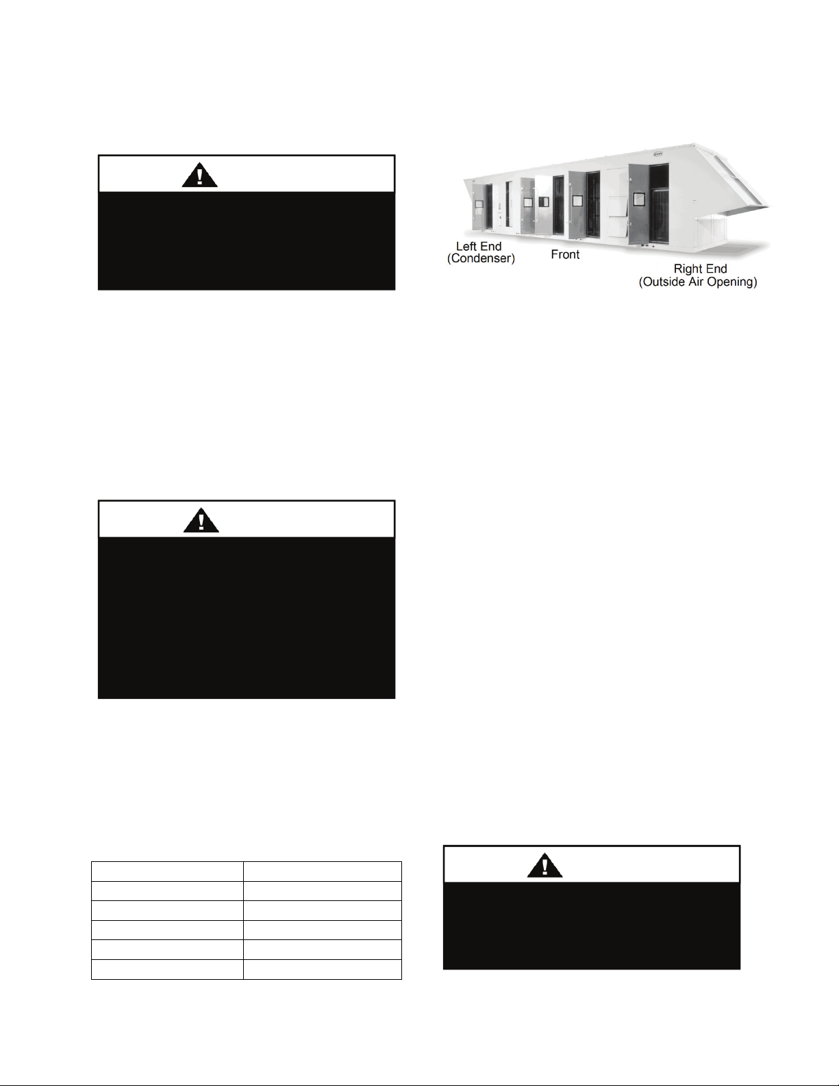
Figure 1 - RL Series Unit Orientation
Condenser coils and fans must be free of any
obstructions in order to start and operate
properly with a correct amount of airflow.
For proper unit operation, the immediate
area around the condenser must remain free
of debris that may be drawn in and obstruct
airflow in the condensing section.
Consideration must be given to obstruction
caused by snow accumulation when placing
the unit.
Curb Installation
Make openings in the roof decking large
enough to allow for duct penetrations and
workspace only. Do not make openings
larger than necessary. Set the curb to
coincide with the openings. Make sure curb
is level.
Unit specific curb drawing is included with
job submittal. See SMACNA Architectural
Sheet Metal Manual and HVAC Duct
Construction Standards for curb installation
details.
All roofing work should be performed
by competent roofing contractors to
avoid any possible leakage.
N
25
Page 26
CAUTIO
Where the supply or warm air duct
passes through a combustible roof, a
clearance of 1 inch must be
maintained between the outside
edges of the duct and combustible
material in accordance with National
Fire Protection Association Standard
No. 90A. Provide flashings or
enclosure between structure and roof
and all joints must be sealed with
mastic roofing to ensure a watertight
seal.
N
For horizontal return and discharge
applications, total height of mounting rail
and unit base rail must be high enough so
that adequate condensate drain p-trap can be
included. Units require steel mounting rail
support along all four sides of the unit base.
When installed at ground level, a one-piece
concrete slab should be used with footings
that extend below the frost line. Care must
also be taken to protect the coil and fins
from damage due to vandalism or other
causes.
If unit is elevated a field supplied catwalk is
recommended to allow access to unit service
doors.
This unit ships with a curb gasket that is
1¼” wide and 1½” tall. It is recommended
that this or another similar gasket be used
between the curb and the unit to reduce
vibration from the unit to the building.
Duct Connection
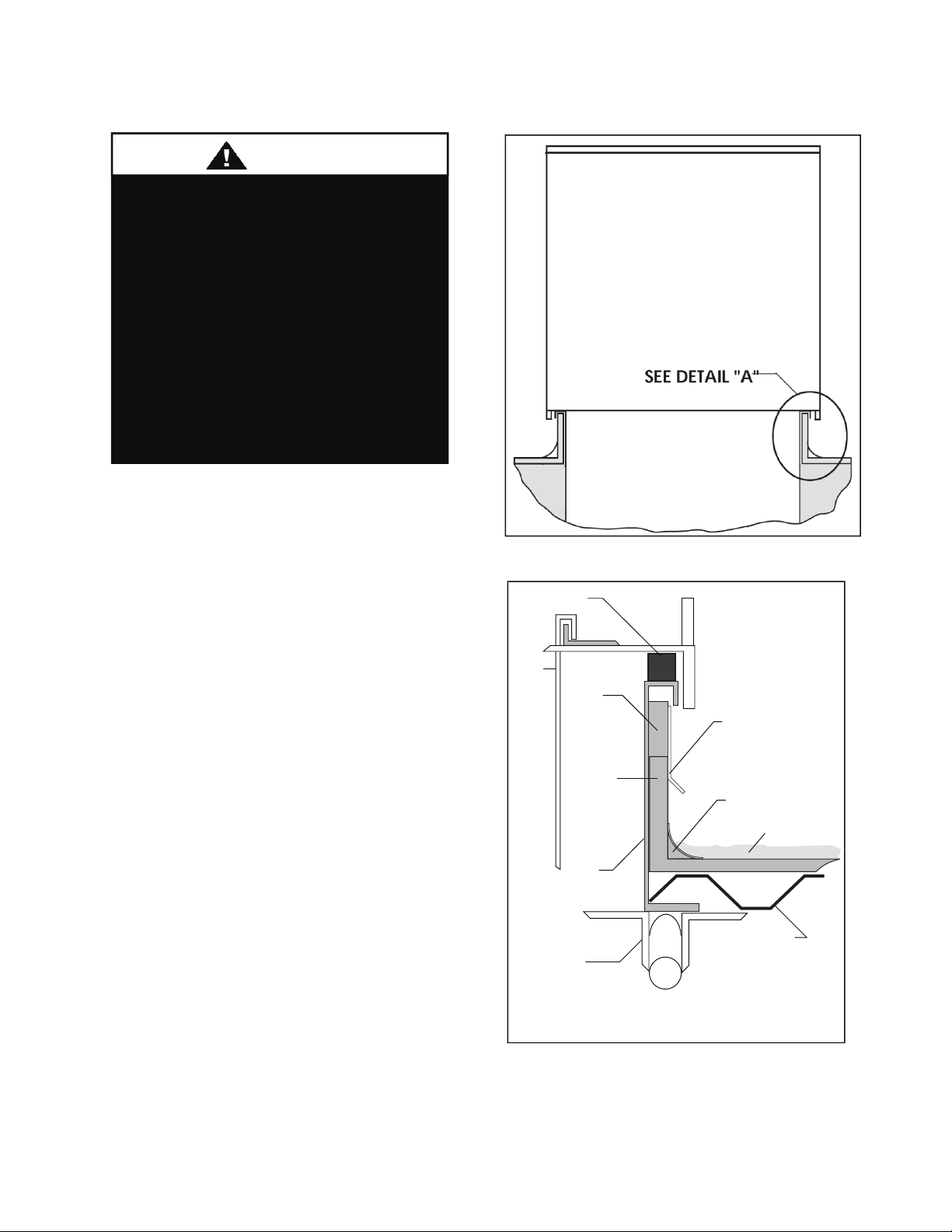
Figure 2 - Curb Mounting
Rubber Gasket
Duct
*
Wood Nailer
Rigid
Installation
Curb
Structural
Steel
Counter
Cant Strip *
Roong Material
Roof Deck
26
Detail ‘A’
* Field Supplied
Figure 3 - Curb Detail
Page 27
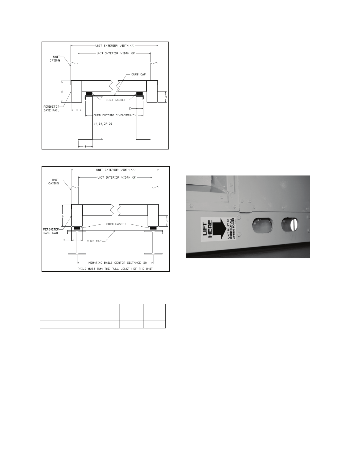
Figure 4 - Curb Mounting with Dimensions
with the outside air hood in the open
position.
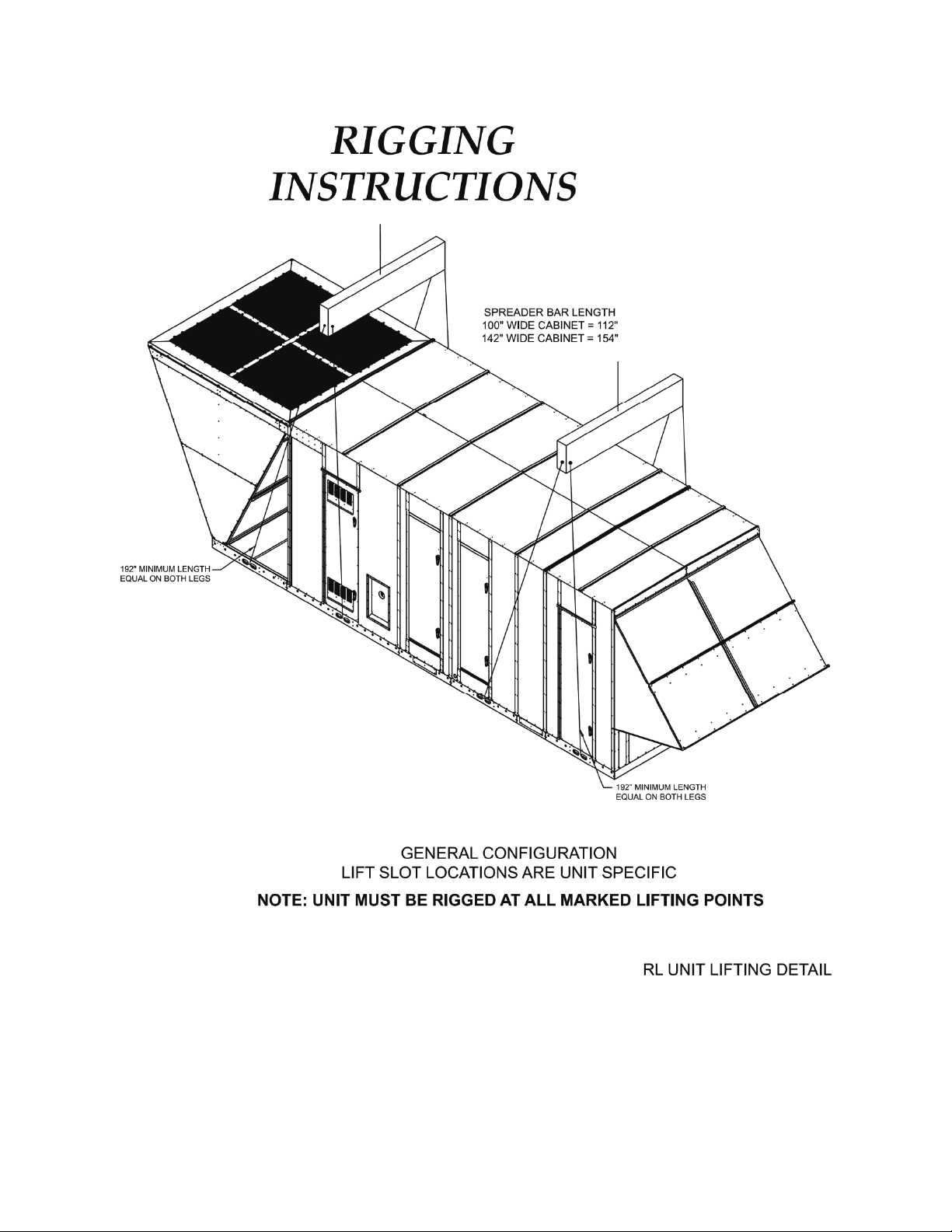
Before lifting unit, be sure that all shipping
material has been removed from the unit.
Secure hooks and cables at all marked lifting
points provided on the unit.
Hoist unit to a point directly above the curb
and duct openings. Be sure that the gasket
material has been applied to the curb.
Carefully lower and align unit with utility
and duct openings. Lower the unit until the
unit skirt fits around the curb. Make sure the
unit is properly seated on the curb and is
level.
Figure 5 - Steel Mounting Rail with
Dimensions
Table 2 - Mounting Dimensions
Tons A B C D
45-135 100” 96” 92” 97”
134-230 142” 138” 134” 139”
Lifting the Unit
If cables or chains are used to hoist the unit
they must be the same length. See figure on
the next page for dimensions.
It is recommended to lift the unit with the
outside air hood in the downward shipping
position. However, the unit may be lifted
Figure 6 - Marked Lifting Points
27
Page 28
28
Page 29
Reassembling Split Units
p
CAUTIO
Some RL Series units are built and shipped
in two separate sections.
Shipping covers should be removed from the
ends where the sections will connect.
Lifting and setting the largest section first is
recommended, checking for the correct
location and position.
In order to simplify the connection of the
two sections, it is important to position and
set the second section as close as possible to
the first section. This will allow the use of a
come-along tool, to pull the second section
against the first section. One come-along
tool is required on each side of the unit,
connected at the base slots. The two sections
must be tightly adjoined before the splicing
parts can be installed.
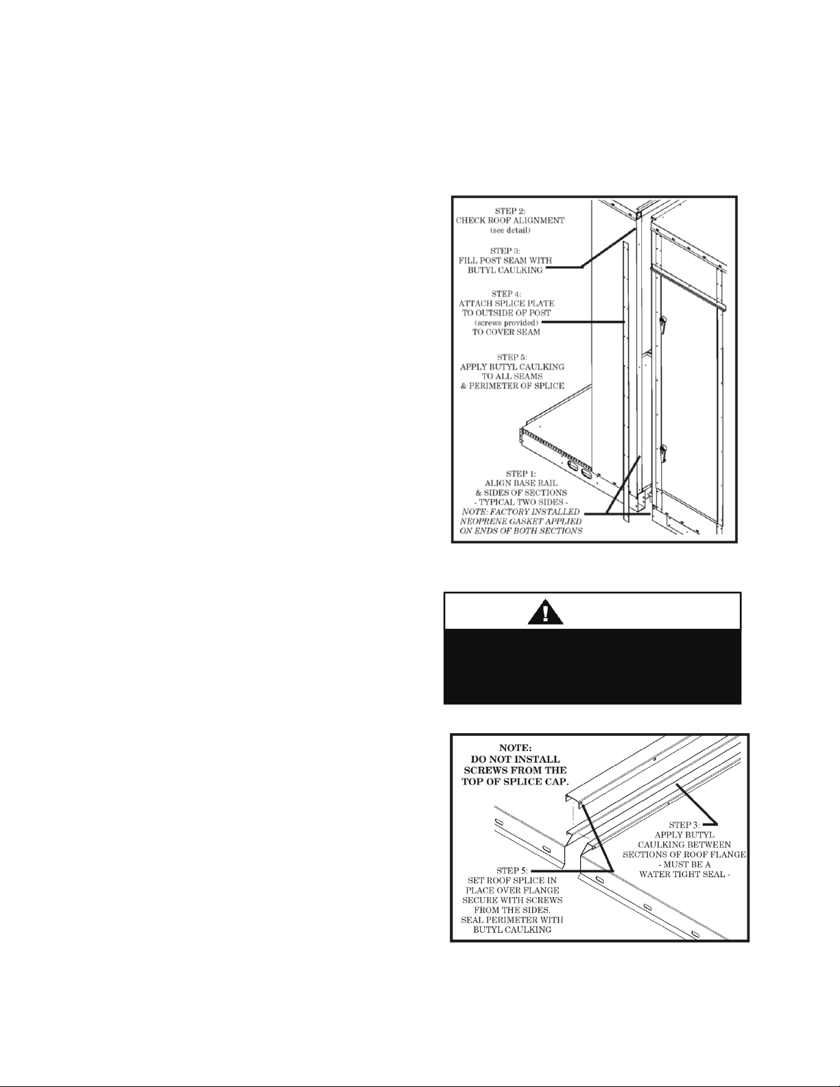
All parts required for splicing the sections
together are factory provided. Neoprene
gasket is provided to be applied on ends of
both sections.
Once the unit is completely assembled, it is
important to visually inspect all exposed
areas and fill any gaps with butyl caulking.
Splicing
1. Align base rail and side sections.
2. Check roof alignment and connecting
flange.
3. Fill post seam with butyl caulking.
Apply butyl caulking between roof
flange sections.
4. Attach splice plate to outside of post to
cover seam. Splice plate is typically
required on both sides of the unit.
5. Install factory provided roof splice cap
over the two sections connecting flange
and secure with screws along the length
of the cap.
6. Apply butyl caulking to all seams and
perimeter of splice and to the perimeter
of the roof splice cap against the roof of
the unit.
Figure 7 - Unit Base and Sides
Attach splice cap with screws from
each side of the cap only. Do not
install screws from the to
Figure 8 - Unit Roof Flange Splice Detail
N
.
29
Page 30
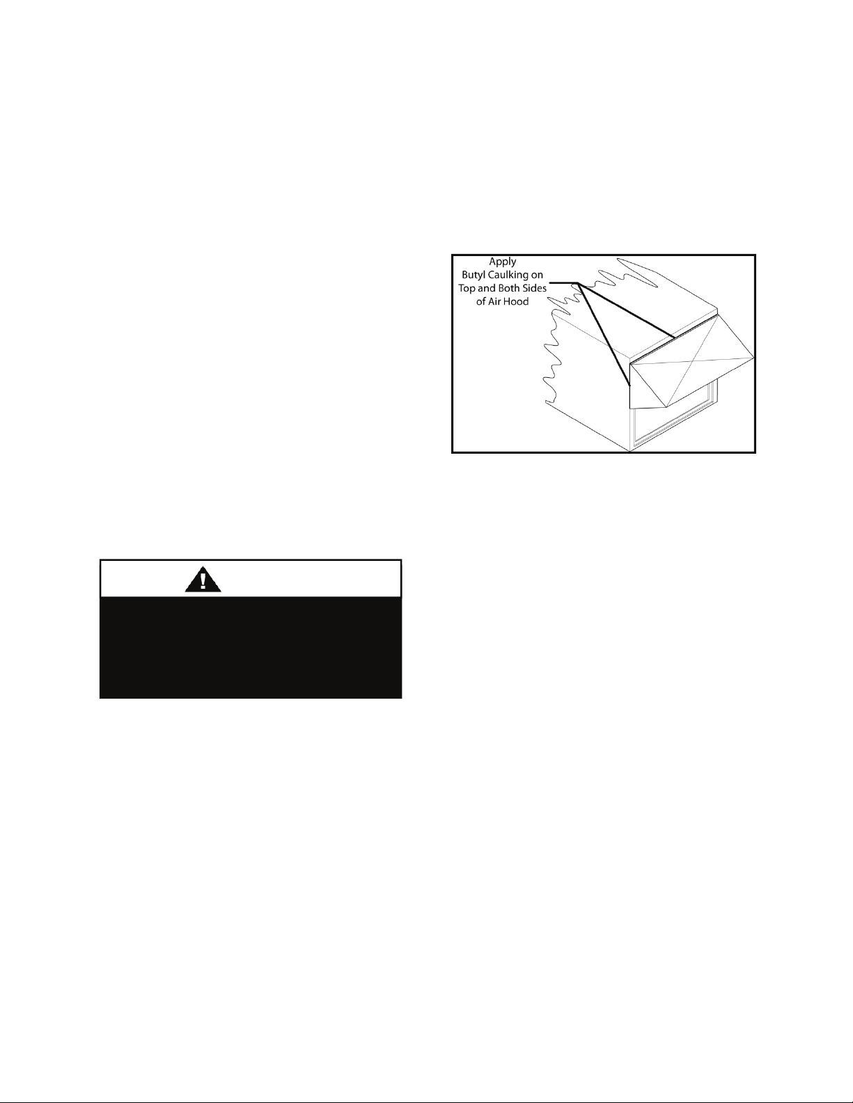
CAUTIO
Electrical Connection of Split Units
Before attempting to make wire connections
between sections it is important to refer to
the unit specific wiring diagram located in
the unit controls compartment to obtain
additional details related to the wiring of the
specific unit.
Adjoining sections are factory wired and
ready for field connection. The electrical
wiring is unit specific and designed
according to the overall unit configuration.
A factory supplied and mounted terminal
block is located in the main section of the
unit that must be used in making the roughin wire connections.
Each wire being spliced from section to
section is tagged at both ends according to
its termination. Junctions for wiring the
sections together are separated according to
voltage.
All wire terminations MUST BE made
before applying power to the unit.
The unit will not operate unless all
circuits are made.
N
Outside Air Rain Hood
For proper unit operation, the outside air
hood must be opened at start-up as shown
below:
Remove shipping screws from each side of
the closed hood.
Lift hood outward to the open position and
secure with sheet metal screws. Apply butyl
caulking along the top and both sides of the
rain hood. Take care to seal the top corners
where the rain hood attaches to the unit.
Outdoor air intake adjustments should be
made according to building ventilation or
local code requirements.
Air hoods vary according to unit size and
options. Figure below is shown as a practical
guideline for all outside air rain hoods.
Figure 9 - Air Hood Shown in the Open
Position
End Flashing Installation
On RL Series D and E cabinet units which
are 142” wide (RL-150, 155, 180, 190, 210,
230) the cabinet width will overhang the
trailer on each side.
In order to secure and protect the unit during
transit the sheet metal end flashings have
been removed from the unit. The slot created
at the base of each end of the unit allows the
unit to set firmly on the trailer deck.
Sheet metal flashings are shipped loose with
the unit and once the unit is set into place
the flashings must be installed on each end
of the unit to complete the finished seal at
the base. The flashings are unit specific and
designed to cover the slot at each end of the
unit to prevent water run-off into the curb.
Failure to attach and seal the end of unit
with the flashings will result in water
leakage into the curb.
30
Page 31

Figure 10 - Factory Supplied End Flashings
CAUTIO
G
CAUTIO
In order to prevent water leakage into
the roof curb, the factory provided
sheet metal flashings MUST BE
attached to the unit base to cover the
shipping slots at both ends of the
unit.
N
Vestibule Exhaust Fan
Prior to unit operation of units with service
vestibules the exhaust fan shipping support
must be removed from the exterior of the
unit
The exhaust fan also includes a factory
provide exterior rain hood which must be
installed.
Figure 11 - Vestibule Exhaust Fan
Electrical
Verify the unit nameplate agrees with power
supply. Connect power and control field
wiring as shown on the unit specific wiring
diagram provided laminated and attached to
the door in the controls compartment.
Electric shock hazard. Before
attempting to perform any installation,
service, or maintenance, shut off all
electrical power to the unit at the
disconnect switches. Unit may have
multiple power supplies. Failure to
disconnect power could result in
dangerous operation, serious injury,
death or property damage.
WARNIN
Route power and control wiring, separately,
through the utility entry in the base of the
unit. Do not run power and signal wires in
the same conduit.
Size supply conductors based on the unit
MCA rating. Supply conductors must be
rated a minimum of 167°F (75°C).
Protect the branch circuit in accordance with
code requirements. The unit must be
electrically grounded in accordance with
local codes, or in the absence of local codes,
the current National Electric Code,
ANSI/NFPA 70 or the current Canadian
Electrical Code CSA C22.1.
Wire power leads to the unit’s terminal
block or main disconnect. All wiring beyond
this point has completed by the
manufacturer and cannot be modified
without effecting the unit’s agency/safety
certification.
Installing Contractor is responsible
for proper sealing of the electrical
and gas entries into the unit Failure
to seal the entries may result in
damage to the unit and property.
N
31
Page 32

CAUTIO
CAUTIO
Figure 12 - Terminal Block
Startup technician must check for proper
motor rotation and check blower motor
amperage listed on the motor nameplate is
not exceeded. Motor overload protection
may be a function of the variable frequency
drive and must not be bypassed.
Note: All units are factory wired for
208/230V, 460V, or 575V. If unit is to be
connected to a 208V supply, the transformer
must be rewired to 208V service. For 208V
service interchange the yellow and red
conductor on the low voltage control
transformer.
Red-Black for 208V
Yellow-Black for 230V
Wire control signals to the unit’s low
voltage terminal block located in the
controls compartment.
If any factory installed wiring must be
replaced, use a minimum 221°F (105°C)
type AWM insulated conductors.
Rotation must be checked on all
MOTORS AND COMPRESSORS of
three phase units. Supply air blower,
exhaust air blower, return air blower,
and condenser fan motors should all
be checked by a qualified service
technician at startup and any wiring
alteration should only be made at the
unit power connection. Variable
frequency drives are programmed to
automatically rotate the fan in the
correct rotation. Do not rely on fans
with variable frequency drives for
compressor rotation.
Scroll compressors are directional
and will be damaged by operation in
the wrong direction. Low pressure
switches on compressors have been
disconnected after factory testing.
Rotation should be checked by a
qualified service technician at startup
using suction and discharge pressure
gauges and any wiring alteration
should only be made at the unit
power connection.
N
N
32
Page 33

Gas Heating
Read the entire gas heating
installation section of this manual
before beginning installation of the
gas heating section.
If you do not follow these instructions
exactly, a fire or explosion may result
causing property damage, personal
injury or loss of life.
WARNING
FOR YOUR SAFETY
Gas piping must be installed in accordance
with local codes, or in the absence of local
codes, installation must conform to the
current (United States) National Fuel Gas
Code ANSI-Z223.1/NFPA 54 or the current
(Canada) National Fuel & Propane
Installation Code CSA B149.1 or B149.2.
Table 3 - Gas Piping Connections
Model
Option
B2
1, 2, 3,
or 4
Quantity of
Heat
Exchangers
Connections
Quantity Size
8 or less 1 2”
5 or 6 10 or 12 1 3”
Do not use gas piping smaller than unit gas
connections. Natural gas pipe runs longer
than 20 feet may require a larger supply pipe
than the unit connection size. Some utility
companies may also require pipe sizes larger
than the minimum sizes listed.
See unit nameplate for unit gas heating
capacities or the Unit Rating Sheet, which
can be obtained from the AAON sales
representative.
Table 4 - Natural Gas Maximum Piping Capacities (ft3/hr)
- Specific Gravity = 0.6, Supply Pressure ≤ 0.5 psi, Pressure Drop = 0.5” w.c.
Length of Pipe
Pipe Size
20 ft 50 ft. 100 ft. 150 ft. 200 ft.
2” 2785 1696 1165 936 801
2-1/2” 4437 2703 1857 1492 1277
3” 7843 4778 3284 2637 2257
3-1/2” 11484 6995 4808 3861 3304
4” 15998 9745 6698 5378 4603
Piping Sizing Example
A 100 ft pipe run is needed for a 1710 MBH
natural gas heater. The natural gas has a
rating of 1000 BTU/ft
3
and a specific gravity
of 0.6 (Obtain these values from the local
gas supplier.)
3
1710
MBH
ft
1000
BTU
=×
1710 ft3/hr
Inlet and Manifold Pressures
For natural gas units, the minimum inlet gas
pressure to the unit is 6” w.c. and maximum
inlet gas pressure to the unit is 10.5” w.c.
For propane units, the minimum inlet gas
pressure to the unit is 11” w.c. and the
maximum inlet gas pressure to the unit is
13” w.c. A field provided 1/8” NPT pressure
tap is required to be installed in the piping
From the natural gas maximum capacities
table, at 100 ft and 1710 ft3/hr the required
minimum pipe size is 2-1/2”.
just upstream of the shutoff valve for test
gage connection to allow checking of the
gas supply pressure at the unit.
33
Page 34

CAUTIO
A factory installed pressure tap on the outlet
end of the gas valve can be used to verify a
manifold pressure of 3.5” w.c. for natural
gas, or 10.5” w.c. for propane. For two
stage gas valves, the low stage setting
should be set at 1.1” w.c. for natural, 5.0”
w.c. for propane. For modulating heaters,
the safety shut-off valve would be set
following the instructions above, then from
a provided pressure tap in the gas train
immediately preceding the burner manifold
the modulating valve is set maintain a
maximum of 3.5” w.c. and a minimum
of 0.4” w.c.
Heater should be disconnected from
the gas supply piping during pressure
testing of the supply piping system
with pressures in excess of ½ psi. Gas
valves can be damaged if subjected to
more than ½ psi.
N
Gas Pressure Regulator & Overpressure
Protection Device
A gas pressure regulator must be installed if
natural gas supply pressure to the unit is
greater than 10.5” w.c. and if propane gas
supply pressure is greater than 13” w.c.
Regulators must comply with the latest
edition of the Standard for Line Pressure
Regulators, ANSI Z21.80/CSA 6.22.
Both a gas pressure regulator and
overpressure protection device (OPD) must
be installed if gas supply pressure to the unit
is greater than 2 psi (55.4” w.c.) and less
than 5 psi (138.4” w.c.), in compliance with
ANSI Z21.80/CSA 6.22. For proper heater
operation, pressure to the regulator MUST
NOT be greater than 5 psi (138.4” w.c.).
Piping Supports
Gas supply piping must be supported
directly at the connection to the unit and at
intervals listed in the following table with
metal straps, blocks, or hooks. Piping should
not be strained or bent.
Table 5 - Piping Support Intervals
Pipe Size
Support
Intervals
1/2” to 3/4” Every 6 ft
3/4” to 1” Every 8 ft
1-3/4” or Larger (Horizontal) Every 10 ft
1-1/4” or Larger (Vertical) Every Floor
Additional Gas Piping Considerations
Local codes will usually require a field
provided and installed manual main shutoff
valve and union external the unit. Main
shutoff valve should be labeled. A field
provided 1/8” NPT pressure tap is required
to be installed in the piping just upstream of
the shutoff valve for test gage connection to
allow checking of the gas supply pressure at
the unit. A drip leg should be installed near
the unit connection to trap sediment and
condensate. Pipe joint compounds used on
all gas piping connections should be
resistant to liquid petroleum gases.
Leak Testing
All components of gas supply system,
including manual shut off valves and the
piping in the interior of the unit, should be
leak tested with a soap solution before
operating the appliance and at least on an
annual basis thereafter.
Do not use open flame or other
source of ignition for leak testing. Fire
or explosion could result causing
property damage, personal injury, or
death.
DANGER
34
Page 35

CAUTIO
The gas pipe in the unit should be
checked for leaks before startup.
Leak checking is the responsibility of
the installing contractor. All
connections should be checked for
leaks annually after installation.
Failure to leak check could result in
fire, explosion, or other hazardous
situations.
DANGER
LEAK CHECK GAS PIPE
Some soaps used for leak detection
can be corrosive to certain metals.
Rinse piping thoroughly after leak
test has been completed.
N
All gas fired heat exchangers are completely
tested at the factory before shipment. This
will remove nearly all of the oils that have
been used in the manufacturing process.
However, trace amounts may remain. When
performing the initial startup at the jobsite, it
is highly recommended that people or any
other living animals that may be sensitive to
the residual odors or gases, NOT be present
in the conditioned space during the startup.
In all cases, including the initial factory
firing and testing, any of the gases will be
under the acceptable level of concentration
for human occupancy.
Those sensitive to odors or gases
from trace amounts of residual oils
should NOT be present in the
conditioned space during the startup
of a gas fired installation.
WARNING
Installation of the gas heaters should be
adjusted to obtain an air temperature rise
within the range specified on the rating
plate.
Rain Hoods
Gas heating units include factory provided
exterior rain hoods. The hoods are fastened
in place with sheet metal screws. Higher
heating capacity units will have two banks
of gas fired heat exchanges (see Figure 13).
All of the provided hoods must be installed
after the unit is set in place.
Figure 13 - Gas Heater Rain Hood
35
Page 36

CAUTIO
Figure 14 - Gas Heater Rain Hood Screws
All exterior heater rain hoods must be
in place before the gas fired heater is
initially started. Improper and
dangerous operating conditions will
otherwise result.
When locating gas fired units, it is
recommended the unit be installed so
that the flue discharge vents are
located at least 120 inches away
from any opening through which
combustion products could enter the
building.
WARNING
WARNING
Condensate Drain Piping
Unit is equipped with 2 or more condensate
drain pan connections. A drain line with ptrap must be installed on every drain
connection, with the p-trap not to exceed 6”
from the drain connection. The lines should
be the same pipe size or larger than the drain
connection and pitched away from the unit
at least 1/8 inch per foot. An air break
should be used with long runs of condensate
lines.
Unit should not be operated without a
p-trap. Failure to install a p-trap may
result in overflow of condensate
water into the unit.
N
All drain connections must be used and
individually trapped to ensure a minimum
amount of condensate accumulation in the
drain pans. ABS type cement should be used
to join the drain pipe connections.
Note: The drain pan connections are 1.5”
MPT fitting.
Condensate drain trapping and piping should
conform to all applicable governing codes.
Drainage of condensate directly onto the
roof may be acceptable in certain areas, refer
to local codes. If condensate is to drain
directly onto the roof a drip pad should be
placed below the drain to protect the roof
from possible damage.
Draw-through cooling coils will have a
negative static pressure in the drain pan area.
This will cause an un-trapped drain to back
up due to air being pulled up through the
condensate drain piping. Blow-through coils
will have a positive static pressure in the
drain pan. The condensate piping on these
drain pans must be trapped to prevent
pressure loss through the drain.
36
Page 37

Draw-Through Coils
Figure 15 - Draw-Through Drain Trap
The X dimension on the draw-through trap
should be at least equal to the absolute value
of the negative static pressure in the drain
pan plus one inch. To calculate the static
pressure at the drain pan add the pressure
drops of all components upstream of the
drain pan, including the cooling coil, and
add the return duct static pressure. Include
the dirt allowance pressure drop for the
filters to account for the worst-case scenario.
The height from top of the bottom bend of
the trap to the bottom of the leaving pipe
must be at least equal to one half of the X
dimension. This ensures that enough water
is stored in the trap to prevent losing the
drain seal during unit startup
Note: The absolute value of the fan inlet
pressure will always be greater than or equal
to the absolute value of the static pressure in
the drain pan on draw-through units, so the
fan inlet pressure is a safe value to use for
the drain pan static pressure.
Table 6 - Draw-Through Drain Trap
Dimensions
Draw-Through
Drain Pan Pressure Trap Dimensions
Negative Static X X/2
(inches of water) (inch) (inch)
-0.50 1.50 0.75
-1.00 2.00 1.00
-1.50 2.50 1.25
-2.00 3.00 1.50
-2.50 3.50 1.75
-3.00 4.00 2.00
-3.50 4.50 2.25
-4.00 5.00 2.50
-4.50 5.50 2.75
-5.00 6.00 3.00
-5.50 6.50 3.25
-6.00 7.00 3.50
-6.50 7.50 3.75
-7.00 8.00 4.00
-7.50 8.50 4.25
-8.00 9.00 4.50
Blow-Through Coils
Figure 16 - Blow-Through Drain Trap
The Y dimension of blow-through traps
should be at least equal to the value of the
positive pressure in the drain pan plus one
inch. This ensures that there will be enough
water stored in the trap to counter the static
pressure in the drain pan. To find the
pressure subtract any pressure drops
between the drain pan and the supply fan
from the fan discharge pressure. The worstcase scenario for blow-through coils is the
37
Page 38

CAUTIO
CAUTIO
CAUTIO
minimum pressure drop, so do not include
dirt allowance pressure drops for filters.
The bottom of the leaving pipe should be at
least one half inch lower than the bottom of
the drain pan connection. This ensures
proper drainage when the unit is not
running.
Note: It may be necessary to fill the trap
manually, or the trap can be filled
automatically by operating the unit until
enough condensate collects to fill the trap.
The trap will then be filled when the unit is
turned off.
Table 7 - Blow-Through Drain Trap
Dimensions
Blow-Through
Drain Pan Pressure Trap Dimension
Positive Static Y
(inches of water) (inch)
0.5 1.5
1.0 2.0
1.5 2.5
2.0 3.0
2.5 3.5
3.0 4.0
3.5 4.5
4.0 5.0
4.5 5.5
5.0 6.0
5.5 6.5
6.0 7.0
6.5 7.5
7.0 8.0
7.5 8.5
8.0 9.0
All condensate drains must be
trapped individually before they are
connected to a common line.
N
N
All condensate drain connections
must be used. Drain pans are sloped
towards connections.
Hot Water/Steam Heating and Chilled
Water Cooling Coils
Internal header connections are provided for
field connection of control valves and
piping. Chilled water piping case will be
provided in the base of the unit, through the
drain pan, for routing water piping.
N
Installing Contractor is responsible
for proper sealing of the water piping
entries into the unit Failure to seal the
entries may result in damage to the
unit and property.
Evaporative-Cooled Condenser
There are two field water connections that
must be made for the evaporative-cooled
condenser. There is a 3/4” PVC socket city
makeup water connection and a 2” PVC
socket drain connection. This drain should
connect to a sanitary sewer or other code
permitted drain. These connections can go
through the base or the wall of the unit.
There is a cutout in the base with a cap that
is 1” tall and the cap is sealed to the unit
base to prevent any leaks in the unit from
penetrating into the building. Any piping
through the base should go through a field
cutout in this cap. The pipes must be sealed
to the cap once the piping is complete to
prevent any leaks in the unit from
penetrating into the building.
38
Page 39

A field cutout must be made in the wall if
the evaporative-cooled condenser piping is
to go through the unit wall. This cutout must
be sealed once the piping is installed to
prevent water from leaking into the unit.
Figure 17 - Evaporative-Cooled Cond. Section, Including Field Water Connections and Base
Cutout
39
Page 40

G
Energy Recovery Units
Improper installation, adjustment,
alteration, service or maintenance
can cause property damage,
personal injury or loss of life. Startup
and service must be performed by a
Factory Trained Service Technician.
General Information
AAONAIRE® units have been equipped
with an energy recovery wheel. This section
is provided to assure the energy recovery
feature will be properly setup to perform in
accordance with the job specifications for
your particular application.
The Energy Recovery Cassette consists of a
frame wheel, wheel drive system, and
energy transfer segments. Segments are
removable for cleaning or replacement. The
segments rotate through counter flowing
exhaust and outdoor air supply streams
where they transfer heat and/or water vapor
from the warm, moist air stream to the
cooler and/or drier air stream.
The initial setup and servicing of the energy
recovery wheel is very important to maintain
WARNIN
Energy Recovery Wheel
proper operation efficiency and building
occupant comfort.
Normal maintenance requires periodic
inspection of filters, the cassette wheel,
drive belts, air seals, wheel drive motor, and
its electrical connections.
Wiring diagrams are provided with each
motor. When wired according to wiring
diagram, motor rotates clockwise when
viewed from the shaft/pulley side.
By carefully reviewing the information
within this section and following the
instructions, the risk of improper operation
and/or component damage will be
minimized.
It is important that periodic maintenance be
performed to help assure trouble free
operation.
Initial Mechanical Check and Setup
Outdoor units equipped with outside air
intake will have an outside air hood. The
outside air hood must be opened prior to unit
operation.
Outdoor air intake adjustments should be
made according to building ventilation, or
local code requirements.
After the unit installation is complete, open
the cassette access door and determine that
the energy wheel rotates freely when turned
by hand. Apply power and observe that the
wheel rotates at approximately 30 RPM. If
the wheel does not rotate when power is
applied, it may be necessary to readjust the
“diameter air seals”.
40
Page 41

Air Seal Adjustments
p
G
Pile type air seals across both sides of the
energy wheel diameter are factory adjusted
to provide close clearance between the air
seal and wheel. Racking of the unit or
cassette during installation, and/or mounting
of the unit on a non-level support or in other
than the factory orientation can change seal
clearances. Tight seals will prevent rotation.
Cross Section of Air Seal Structure
Wheel to Air Seal Clearance
To check wheel to seal clearance; the energy
recovery wheel is accessible inside the
walk-in cabinet.
A business card or two pieces of paper can
be used as a feller gauge, (typically each
.004” thick) by placing it between the face
of the wheel and pile seal.
Using the paper, determine if a loose slip fit
exist between the pile seal and wheel when
the wheel is rotated by hand.
To adjust air seal clearance, loosen all seal
plate retaining screws holding the separate
seal retaining plates to the bearing support
channels and slide the seals plates away
from the wheel. Using the paper feeler
gauge, readjust and retighten one seal plate
at a time to provide slip fit clearance when
the wheel is rotated by hand.
Confirm that the wheel rotates freely. Apply
power to the unit and confirm rotation.
Airflow Balancing and Checking
High performance systems commonly have
complex air distribution and fan systems.
Unqualified personnel should not attempt to
adjust fan operation, or air circulation, as all
systems have unique operations
characteristics. Professional air balance
specialists should be employed to establish
actual operating conditions, and to configure
the air delivery system for optimal
performance.
Controls
A variety of controls and electrical
accessories may be provided with the
equipment. Identify the controls on each unit
by consulting appropriate submittal, or order
documents, and operate according to the
control manufacturer’s instructions. If you
cannot locate installation, operation, or
maintenance information for the specific
controls, then contact your sales
representative, or the control manufacturer
for assistance.
Do not alter factory wiring. Deviation
from the supplied wiring diagram will
void all warranties, and may result in
equipment damage or personal
injury. Contact the factory with wiring
discre
Routine Maintenance and Handling
Handle cassettes with care. All cassettes
should be lifted by the bearing support
beam. Holes are provided on both sides of
the bearing support beams to facilitate
rigging as shown in the following
illustration.
WARNIN
ancies.
41
Page 42

CAUTIO
Lifting Hole Locations
Routine maintenance of the Energy
Recovery Cassettes includes periodic
cleaning of the Energy Recovery Wheel as
well as inspection of the Air Seals and
Wheel Drive Components as follows:
Cleaning
The need for periodic cleaning of the energy
recovery wheel will be a function of
operating schedule, climate and
contaminants in the indoor air being
exhausted and the outdoor air being supplied
to the building.
The energy recovery wheel is “selfcleaning” with respect to dry particles due to
its laminar flow characteristics. Smaller
particles pass through; larger particles land
on the surface and are blown clear as the
flow direction is reversed. Any material that
builds up on the face of the wheel can be
removed with a brush or vacuum. The
primary need for cleaning is to remove oil
based aerosols that have condensed on
energy transfer surfaces.
A characteristic of all dry desiccants, such
films can close off micron sized pores at the
surface of the desiccant material, reducing
the efficiency by which the desiccant can
adsorb and desorb moisture and also build
up so as to reduce airflow.
In a reasonably clean indoor environment
such as a school or office building,
measurable reductions of airflow or loss of
sensible (temperature) effectiveness may not
occur for several years. Measurable changes
in latent energy (water vapor) transfer can
occur in shorter periods of time in
applications such as moderate occupant
smoking or cooking facilities. In
applications experiencing unusually high
levels of occupant smoking or oil based
aerosols such as industrial applications
involving the ventilation of machine shop
areas for example, annual washing of energy
transfer may be necessary to maintain latent
transfer efficiency. Proper cleaning of the
energy recovery wheel will restore latent
effectiveness to near original performance.
To clean, gain access to the energy recovery
wheel and remove segments. Brush foreign
material from the face of the wheel. Wash
the segments or small wheels in a 5%
solution of non-acid based coil cleaner or
alkaline detergent and warm water.
Do Not use acid based cleaners,
aromatic solvents, steam or
temperatures in excess of 170°F;
damage to the wheel may occur!
Soak in the solution until grease and tar
deposits are loosened (Note: some staining
of the desiccant may remain and is not
harmful to performance). Before removing,
rapidly run finger across surface of segment
to separate polymer strips for better cleaning
action. Rinse dirty solution from segment
N
42
Page 43

and remove excess water before reinstalling
in wheel.
Air Seals
Four adjustable diameter seals are provided
on each cassette to minimize transfer of air
between the counter flowing airstreams.
To adjust diameter seals, loosen diameter
seal adjusting screws and back seals away
from wheel surface. Rotate wheel clockwise
until two opposing spokes are hidden behind
the bearing support beam. Using a folded
piece of paper as a feeler gauge, position
paper between the wheel surface and
diameter seals.
Adjust seals towards wheel surface until a
slight friction on the feeler gauge (paper) is
detected when gauge is moved along the
length of the spoke. Retighten adjusting
screws and recheck clearance with “feeler”
gauge.
Wheel Drive Components
The wheel drive motor bearings are prelubricated and no further lubrication is
necessary.
The wheel drive pulley is secured to the
drive motor shaft by a combination of either
a key or D slot and set screw.
The set screw is secured with removable
locktite to prevent loosening. Annually
confirm set screw is secure. The wheel drive
belt is a urethane stretch belt designed to
provide constant tension through the life of
the belt. No adjustment is required. Inspect
the drive belt annually for proper tracking
and tension. A properly tensioned belt will
turn the wheel immediately after power is
applied with no visible slippage during startup.
Installation Considerations
Energy recovery cassettes are incorporated
within the design of packaged units,
packaged air handlers and energy recovery
ventilators. In each case, it is recommended
that the following considerations be
addressed:
Accessibility
The cassette and all its operative parts; i.e.:
motor, belt, pulley, bearings, seals and
energy transfer segments must be accessible
for service and maintenance. This design
requires that adequate clearance be provided
outside the enclosure. Where cassettes are
permanently installed in a cabinet, access to
both sides of the cassette must be provided.
Orientation & Support
The Energy Recovery Cassette may be
mounted in any orientation. However, care
must be taken to make certain that the
cassette frame remains flat and the bearing
beams are not racked.
Frame
Bearing beams shown
racked
A
Wheel
Bearing
beams
(2)
C
Flat surface
B
Avoid Racking of Cassette Frame
To verify, make certain that the distance
between wheel rim and bearing beam is the
same at each end of the bearing beam, to
within 1/4 of an inch (dimension A & B).
43
Page 44

CAUTIO
This amount of racking can be compensated
for by adjusting the diameter seals.
If greater than 1/4 inch (dimension C),
racking must be corrected to ensure that
drive belt will not disengage from wheel.
Operation
Keep hands away from rotating
wheel! Contact with rotating wheel
can cause physical injury.
Startup Procedure
1. By hand, turn wheel clockwise (as viewed
from the pulley side), to verify wheel turns
freely through 360º rotation.
2. Before applying power to drive motor,
confirm wheel segments are fully engaged in
wheel frame and segment retainers are
completely fastened. (See Segment
Installation Diagram).
3. With hands and objects away from
moving parts, activate unit and confirm
wheel rotation. Wheel rotates clockwise (as
viewed from the pulley side).
4. If wheel has difficulty starting, turn power
off and inspect for excessive interference
between the wheel surface and each of the
four (4) diameter seals. To correct, loosen
diameter seal adjusting screws and back
adjustable diameter seals away from surface
of wheel, apply power to confirm wheel is
free to rotate, then re-adjust and tighten hub
and diameter seals, as shown in hub seal
adjustment diagram.
5. Start and stop wheel several times to
confirm seal adjustment and to confirm belt
is tracking properly on wheel rim
(approximately 1/4” from outer edge of
rim).
Diameter Seal Adjustment
Hub Seal Adjustment
Service
N
Disconnect electrical power before
servicing energy recovery cassette.
Always keep hands away from
bearing support beam when installing
or removing segments. Failure to do
so could result in severe injury to
fingers or hand.
44
Page 45

Segment Installation & Replacement
Wheel segments are secured to the wheel
frame by a Segment Retainer which pivots
on the wheel rim and is held in place by a
Segment Retaining Catch.
Segment Retainer
To install wheel segments follow steps one
through five below. Reverse procedure for
segment removal.
1. Unlock two segment retainers (one on
each side of the selected segment opening.
2. With the embedded stiffener facing the
motor side, insert the nose of the segment
between the hub plates.
Segment Installation
3. Holding segment by the two outer
corners, press the segment towards the
center of the wheel and inwards against the
spoke flanges. If hand pressure does not
fully seat the segment, insert the flat tip of a
screw driver between the wheel rim and
outer corners of the segment and apply
downward force while guiding the segment
into place.
4. Close and latch each Segment Retainer
under Segment Retaining Catch.
5. Slowly rotate the wheel 180º. Install the
second segment opposite the first for
counterbalance. Rotate the two installed
segments 90º to balance the wheel while the
third segment is installed. Rotate the wheel
180º again to install the fourth segment
opposite the third. Repeat this sequence with
the remaining four segments.
Wheel Drive Motor and Pulley
Replacement
1. Disconnect power to wheel drive motor.
2. Remove belt from pulley and position
temporarily around wheel rim.
3. Loosen set screw in wheel drive pulley
using a hex head wrench and remove pulley
from motor drive shaft.
4. While supporting weight of drive motor in
one hand, loosen and remove (4) mounting
bolts.
5. Install replacement motor with hardware
kit supplied.
6. Install pulley to dimension as shown and
secure set screw to drive shaft.
7. Stretch belt over pulley and engage in
groove.
8. Follow start-up procedure.
Belt Replacement
1. Obtain access to the pulley side bearing
access plate if bearing access plates are
provided. Remove two bearing access plate
retaining screws and the access plate.
2. Using hexagonal wrench, loosen set screw
in bearing locking collar. Using light
45
Page 46

CAUTIO
hammer and drift (in drift pin hole) tap
collar in the direction of wheel rotation to
unlock collar. Remove collar.
3. Using socket wrench with extension,
remove two nuts which secure bearing
housing to the bearing support beam. Slide
bearing from shaft. If not removable by
hand, use bearing puller.
4. Form a small loop of belt and pass it
through the hole in the bearing support
beam. Grasp the belt at the wheel hub and
pull the entire belt down.
Note: Slight hand pressure against wheel
rim will lift weight of wheel from inner race
of bearing to assist bearing removal and
installation.
Protect hands and belt from possible
sharp edges of hole in Bearing
Support Beam.
5. Loop the trailing end of the belt over the
shaft (belt is partially through the opening).
6. Reinstall the bearing onto the wheel shaft,
being careful to engage the two locating pins
into the holes in the bearing support beam.
Secure the bearing with two self-locking
nuts.
7. Install the belts around the wheel and
pulley according to the instructions provided
with the belt.
8. Reinstall diameter seals or hub seal and
tighten retaining screws. Rotate wheel in
clockwise direction to determine that wheel
rotates freely with slight drag on seals.
9. Reinstall bearing locking collar. Rotate
collar by hand in the direction the wheel
rotates (see label provided on each cassette
for wheel rotation).
10. Lock in position by tapping drift pin
hole with hammer and drift. Secure in
position by tightening set screw.
N
11. Reinstall Bearing Access Cover.
12. Apply power to wheel and ensure that
the wheel rotates freely without interference.
Belt Replacement
46
Page 47

Startup
(See back of the manual for startup form)
Supply, Return, and Exhaust Backward
Curved Fans
RL Series units are equipped with direct
drive backward curved fan assemblies that
are selected to deliver the air volume
specified according to unit size and job
requirements. This is either done with air
volume bands in the blower wheels or with
VFDs. Field airflow adjustment may be
required at startup.
Air volume bands for the wheels are sized
according to the unit’s air delivery
specifications and can also be ordered from
the factory for field installation.
Airflow Adjustment
If reduced air volume is required an air
volume band or larger air volume band can
be installed within the blower wheel to
reduce the amount of air delivered by the
wheel.
If the unit is factory equipped with the air
volume band and additional air volume is
required, the band can be removed from the
wheel.
Use fan program in AAONEcat32™ to
determine the new band size for the required
CFM and static pressure.
The following photos of a wheel are
provided for practical guidelines only in
order to identify the air band location in the
wheel. Actual field installation of the air
band into the wheel will require access into
and through the blower wheel venture,
which may require removal of the fan motor
and wheel.
Air volume bands are made of aluminum,
sized and equipped with easy bend tabs that
are to be inserted into pre-punched slots
provided on the wheel. Once the band has
been inserted into the slots, it MUST BE
secured by bending the tabs over from the
back side of the wheel and also MUST BE
secured from the inside by connecting the
ends together with a pop-rivet in the holes
provided on the ends of the band.
Figure 18 - Air Volume Band
If the band is field installed, a hand held
pop-rivet tool is recommended for
connecting the band ends together. Caution
must be taken to assure that the band is
tightly installed and no damage, denting or
alteration to the wheel or blades occurs
during the installation.
Figure 19 - Air Volume Band Tab Locations
47
Page 48

Figure 20 - Securing Air Volume Band Ends
For single set screw applications, tighten the
set screw to the required torque setting
(Table 8) using a calibrated torque wrench.
For double set screw applications, tighten
one set screw to half of the required torque
setting (Table 8) using a calibrated torque
wrench. Tighten the second set screw to the
full required torque setting then tighten the
first set screw to the full required torque
setting.
Table 8 - Plenum Fan Set Screw
Specifications
SET SCREW
DIAMETER
1/4" 80
5/16" 126
3/8" 240
7/16" 384
1/2" 744
TORQUE (IN-LBS)
The gap tolerances that are allowed between
the blower and the inlet cone for the RL
plenum fan blowers are shown in Figure 21.
The inlet cone can be moved as necessary to
center the cone in relation to the blower. The
blower can be moved on the motor shaft to
set the correct overlap. These tolerances are
critical to the performance of the blower.
Figure 21 - Plenum Fan Gap Tolerances
Power Return and Exhaust Axial Flow
Fans
Blade Pitch Angle Setting Instructions
Step 1: Determine the new required pitch for
the fan blades
Use the fan program in AAONEcat32™.
Step 2: Maintain the balance of fan
Mark the HUB/RET castings across a single
joint, so the fan can be reassembled in the
same orientation.
Mark the location of any balancing weight.
Balancing weight will be on the outer bolt
circle, in the form of washers, and/or longer
bolts, or an additional balancing nut.
Number the blades and blade sockets, so that
they can be replaced into their original
positions.
48
Page 49

Bushing
Mount
Figure 22 - Fan with the HUB on the top and
RET on the bottom.
Step 3: Determine the direction of rotation
Right, R, is clockwise when facing the
discharge side of the fan and Left, L, is
counterclockwise when facing the discharge
side of the fan.
Step 4: Determine the bushing mount
location
The bushing mount is the center section of
the hub through which the fan is mounted to
the shaft, and typically contains either
setscrews or a center-tapered hole where the
bushing inserts.
Location A is with the bushing mount on air
inlet side of the fan.
Location B is with the bushing mount on air
discharge side of the fan.
Step 5: Determine the pin location groove
Disassemble fan on a flat surface and note in
which groove the pin is located.
1 2 3 4
Figure 24 - RET shown with pin in groove 4
Step 6: Determine whether the pin is in the
HUB or RET
Bushing Bushing
A B
Figure 23 - Fan Bushing Mount Location
Bushing
Mount
Figure 25 - HUB and RET
49
Page 50

Step 7: Determine the current blade pitch and the pin location for the new blades
Table 9 - Return/Exhaust Fan Pin Location in the Bushing Mount
Type
5Z
Type Rot.
5Z
Step 8: Replace fan blades in the new pin
location and reassemble the fan
Replace the blades with the pin in the 1, 2,
3, or 4 groove position of either the HUB or
RET. Assemble the fan making sure to place
the blades in their previous blade sockets, to
match up the previous orientation of HUB
Bushing
Mount
A - RET - RET RET RET HUB HUB HUB HUB
B - HUB - HUB HUB HUB RET RET RET RET
R - 4 - 3 2 1 4 3 2 1
L - 1 - 2 3 4 1 2 3 4
20° 25° 28° 30° 33° 35° 38° 40° 45° 50°
Table 10 - Return/Exhaust Fan Pin Location in the Grooves
20° 25° 28° 30° 33° 35° 38° 40° 45° 50°
Blade Pitch Angle
Blade Pitch Angle
and RET and to replace any balancing
weights in their previous locations. Tighten
bolts in a cross pattern to 5-6 ft-lbs. of
torque.
50
Page 51

Adjustable Fan Cycling Switch Procedure
Recommended Settings
The switch will come factory set to cut-in at
425psi (+/– 5psi) or a differential of 155psi
(and open at 270psi (+/– 5psi)).
To adjust the fan cycle switch you will need a
flathead screwdriver.
Settings for CUT IN and DIFFERENTIAL
PRESSURE are indicated with two slider
gauges.
Cut In Differential
Each adjustment screw sits above the setting
that it controls.
51
Page 52

Cut In Gauge
To lower the pressure set point for the CUT IN
gauge, turn the adjustable screw clockwise.
Differential
Gauge
Cut In Gauge
To raise the pressure set point for the CUT IN
gauge, turn the adjustable screw counter
clockwise.
Differential
Gauge
To raise the pressure set point for the
DIFFERENTIAL Gauge, turn the adjustable
screw clockwise.
NOTE: The pressure values on the gauge should be verified with gauges on the refrigerant line.
The gauge scale is for illustration purposes only.
52
To lower the pressure set point for the
DIFFERENTIAL Gauge, turn the adjustable
screw counter clockwise.
Page 53

RL Prop Assembly
The prop assembly bushings should be
tightened to the specifications listed in Table
11.
Table 11 - Prop Assembly Bushing Torque
Specifications
BUSHING
H X 1.125" 95
H X 1.375" 95
SH X 1.125" 108
SH X 1.375" 108
SD X 1.125" 108
SD X 1.375" 108
SD X 1.625" 108
SD X 1.875" 108
SK X 2.125" 180
TIGHTENING TORQUE
(IN-LBS.)
Spring Isolator Adjustment
NOTE: Resonance issues are possible when
both internal and external spring isolation
are used. When an external spring isolated
curb is used, internal fan spring isolators
should be locked down to prevent resonance
issues.
All spring isolators must be adjusted, prior
to unit startup, to avoid mechanical damage
or reduced performance.
1. On all four isolators, secure the
adjustment bolt and rotate the locking
bolt counter-clockwise approximately
four full rotations. This will allow the
locking bolt to spin when the adjustment
bolt is turned (See Figure 26).
2. Take two full counter-clockwise turns on
each adjustment bolt and continue to
evenly compress the springs until the
wooden shipping supports can be
removed and discarded.
3. Adjust all four isolators until 1¼”
clearance is obtained between all spring
brackets and spring supports. Rotating
the adjustment bolts counter-clockwise
will raise the blower frame and increase
the clearance.
4. Adjusting only the front isolators,
increase the clearance on the front
brackets by approximately ¼”. This will
result in a gap between the front of the
blower frame and the upper corners of
the neoprene gasket. The front isolators
should be adjusted until this gap
measures approximately ¼” for units
with three or four blowers, or two
blowers in a vertical configuration
(shown in Figure 27). For units with a
single blower, or two blowers positioned
side by side, the gap should be
approximately 1/8”.
53
Page 54

5. Check all isolators to ensure that the
spring, spring cap and spring base plate
are aligned. The position of the spring
cap should be adjusted such that the
spring is straight up and down.
Adjustments can be made by applying
horizontal pressure to the locking bolt.
6. Individually tighten all four locking
bolts while the adjustment bolts are held
in position.
Figure 27 - Fan Assembly Detail
Figure 26 - Rear Isolator Detail
Back Draft Damper Setup
The counter balance is shipped loose and
may need to be installed during start-up on
some applications. Not all applications will
require the use of the counter balance on the
back draft dampers. If the unit is equipped
with back draft dampers on the supply fan,
the fans should be started without the
counter balance and the operation of the
back draft dampers should be observed. If
54
Figure 28 - Blower Assembly
the back draft dampers do not open
completely, then the counter balance can be
installed to assist with the opening of the
back draft dampers. The counter balance
should be installed in the horizontal position
when the back draft dampers are held closed
(see Figure 29).
Page 55

CAUTIO
Figure 29 - Closed Back Draft Damper
The back draft damper will remain open
with no back pressure on the damper (see
Figure 30). The damper will close
completely when back pressure is applied.
Figure 30 - Open Back Draft Damper
Filters
Do not operate the unit without filters in
place. Unit should be checked for correct
filter placement during startup. Operation of
the equipment without filters will result in
clogged cooling and heating coils.
Cartridge Filter Installation
Cartridge filters may be held in their proper
orientation and placement with channels,
spring fasteners, or clips.
Figure 31 - Top Clip and Side Spring
Fastener Securing Filters in Place
Before completing startup and
leaving the unit a complete operating
cycle should be observed to verify
that all components are functioning
properly.
N
Adjusting Refrigerant Charge
Adjusting the charge of a system in the field
must be based on determination of liquid
sub-cooling and evaporator superheat. On a
system with a TXV liquid sub-cooling is
more representative of the charge than
evaporator superheat but both measurements
must be taken.
The Clean Air Act of 1990 bans the
intentional venting of refrigerant
(CFC’s and HCFC’s) as of July 1,
1992. Approved methods of recovery,
recycling or reclaiming must be
followed. Fines and/or incarceration
CAUTION
Before Charging
Unit being charged must be at or near full
load conditions before adjusting the charge.
Units equipped with hot gas reheat must be
charged with the hot gas reheat valves
55
Page 56

closed while the unit is in cooling mode to
get the proper charge. After charging, unit
should be operated in reheat
(dehumidification) mode to check for
correct operation.
After adding or removing charge the system
must be allowed to stabilize, typically 10-15
minutes, before making any other
adjustments.
The type of unit and options determine the
ranges for liquid sub-cooling and evaporator
superheat. Refer to the table below when
determining the proper sub-cooling.
Checking Liquid Sub-Cooling
Measure the temperature of the liquid line as
it leaves the condenser coil.
Read the gauge pressure at the liquid line
close to the point where the temperature was
taken. You must use liquid line pressure as it
will vary from discharge pressure due to
condenser coil pressure drop.
Convert the pressure obtained to a saturated
temperature using the appropriate refrigerant
temperature-pressure chart.
Subtract the measured liquid line
temperature from the saturated temperature
to determine the liquid sub-cooling.
Compare calculated sub-cooling to the table
below for the appropriate unit type and
options.
Checking Evaporator Superheat
Measure the temperature of the suction line
close to the compressor.
Read gauge pressure at the suction line close
to the compressor.
Convert the pressure obtained to a saturated
temperature using the appropriate refrigerant
temperature-pressure chart.
Subtract the saturated temperature from the
measured suction line temperature to
determine the evaporator superheat.
For refrigeration systems with tandem
compressors, it is critical that the suction
superheat setpoint on the TXV is set with
one compressor running. The suction
superheat should be 10-13°F with one
compressor running. The suction superheat
will increase with both compressors in a
tandem running. Inadequate suction
superheat can allow liquid refrigerant to
return to the compressors which will wash
the oil out of the compressor. Lack of oil
lubrication will destroy a compressor.
Liquid subcooling should be measured with
both compressors in a refrigeration system
running.
Compare calculated superheat to the table
below for the appropriate unit type and
options.
56
Page 57

Table 12 - Acceptable Sub-Cooling and
CAU
Superheat Temperatures
Air-Cooled Condenser
Sub-Cooling
Sub-Cooling with
Hot Gas Reheat
Superheat
2
2
1
12-18°F
15-22°F
10-15°F
Evaporative-Cooled Condenser
Sub-Cooling
Sub-Cooling with
Hot Gas Reheat
Superheat
2
2
1
6-10°F
8-12°F
10-15°F
Water-Cooled Condenser
Sub-Cooling
Sub-Cooling with
Hot Gas Reheat
Superheat
1
One compressor running in tandem
2
Two compressors running in tandem
2
2
1
6-10°F
8-12°F
10-15°F
Adjusting Sub-cooling and Superheat
Temperatures
The system is overcharged if the sub-cooling
temperature is too high and the evaporator is
fully loaded (low loads on the evaporator
result in increased sub-cooling) and the
evaporator superheat is within the
temperature range as shown in the table
above (high superheat results in increased
sub-cooling).
Correct an overcharged system by reducing
the amount of refrigerant in the system to
lower the sub-cooling.
Refrigerant overcharging leads to
excess refrigerant in the condenser
coils resulting in elevated compressor
discharge pressure.
TION
DO NOT OVERCHARGE!
The system is undercharged if the superheat
is too high and the sub-cooling is too low.
Correct an undercharged system by adding
refrigerant to the system to reduce superheat
and raise sub-cooling.
If the sub-cooling is correct and the
superheat is too high, the TXV may need
adjustment to correct the superheat.
Refrigerant Filter Driers
Each refrigerant circuit contains a
replaceable core filter drier. Replacement is
recommended when there is excessive
pressure drop across the assembly or
moisture is indicated in a liquid line sight
glass.
Table 13 - Filter Drier Maximum Pressure
Drop
Circuit Loading Max Pressure Drop
100% 5 psig
50% 2.5 psig
The filter driers are provided with pressure
taps and shutoff valves for isolation when
changing the core. For safety purposes a
service manifold must be attached prior to
filter maintenance.
Figure 32 - Replaceable Core Filter/Drier
57
Page 58

Table 14 - R-410A Refrigerant Temperature-Pressure Chart
PSIG PSIG PSIG PSIG PSIG
R-410A R-22
(°F)
78.3 43.1
20
80.0 44.2
21
81.8 45.3
22
83.6 46.5
23
85.4 47.6
24
87.2 48.8
25
89.1 50.0
26
91.0 51.2
27
92.9 52.4
28
94.9 53.7
29
96.8 55.0
30
98.8 56.2
31
100.9 57.5
32
102.9 58.8
33
105.0 60.2
34
R-410A R-22
(°F)
142.2 84.1
50
144.8 85.7
51
147.4 87.4
52
150.1 89.1
53
152.8 90.8
54
155.5 92.6
55
158.2 94.4
56
161.0 96.1
57
163.8 98.0
58
166.7 99.8
59
169.6 101.6
60
172.5 103.5
61
175.4 105.4
62
178.4 107.3
63
181.5 109.3
64
R-410A R-22
(°F)
234.9 143.6
80
238.6 146.0
81
242.3 148.4
82
246.0 150.8
83
249.8 153.2
84
253.7 155.7
85
257.5 158.2
86
261.4 160.7
87
265.4 163.2
88
269.4 165.8
89
273.5 168.4
90
277.6 171.0
91
281.7 173.7
92
285.9 176.4
93
290.1 179.1
94
R-410A R-22
(°F)
364.1 226.4
110
369.1 229.6
111
374.2 232.8
112
379.4 236.1
113
384.6 239.4
114
389.9 242.8
115
395.2 246.1
116
400.5 249.5
117
405.9 253.0
118
411.4 256.5
119
416.9 260.0
120
422.5 263.5
121
428.2 267.1
122
433.9 270.7
123
439.6 274.3
124
R-410A R-22
(°F)
140
141
142
143
144
145
146
147
148
149
150
540.1 337.4
547.0 341.6
553.9 345.9
560.9 350.3
567.9 354.6
575.1 359.0
582.3 363.5
589.6 368.0
596.9 372.5
604.4 377.1
611.9 381.7
107.1 61.5
35
109.2 62.9
36
111.4 64.3
37
113.6 65.7
38
115.8 67.1
39
118.1 68.6
40
120.3 70.0
41
122.7 71.5
42
125.0 73.0
43
127.4 74.5
44
129.8 76.1
45
132.2 77.6
46
134.7 79.2
47
137.2 80.8
48
139.7 82.4
49
65
66
67
68
69
70
71
72
73
74
75
76
77
78
79
184.5 111.2
187.6 113.2
190.7 115.3
193.9 117.3
197.1 119.4
200.4 121.4
203.6 123.5
207.0 125.7
210.3 127.8
213.7 130.0
217.1 132.2
220.6 134.5
224.1 136.7
227.7 139.0
231.3 141.3
95
96
97
98
99
100
101
102
103
104
105
106
107
108
109
294.4 181.8
298.7 184.6
303.0 187.4
307.5 190.2
311.9 193.0
316.4 195.9
321.0 198.8
325.6 201.8
330.2 204.7
334.9 207.7
339.6 210.8
344.4 213.8
349.3 216.9
354.2 220.0
359.1 223.2
445.4 278.0
125
451.3 281.7
126
457.3 285.4
127
463.2 289.2
128
469.3 293.0
129
475.4 296.9
130
481.6 300.8
131
487.8 304.7
132
494.1 308.7
133
500.5 312.6
134
506.9 316.7
135
513.4 320.7
136
520.0 324.8
137
526.6 329.0
138
533.3 333.2
139
58
Page 59

Indirect Gas Heat Startup
59
Page 60

Access Doors
Lockable access doors are provided to the
services vestibule and to sections of the unit
which may require maintenance or
servicing. After startup is completed, if
necessary, locks should be used with the
doors to prevent unauthorized access.
Figure 33 - Lockable Door Handles
60
Page 61

Operation
G
Unit operations should be controlled with
thermostat, or unit controller, never at the
main power supply, except for emergency or
complete shutdown of the unit.
Indirect Gas Heater Operation
When heat (G and W1, W2, etc.) is called
for the combustion motor starts and the
ignition control is energized. The control
sends 24 VAC to the gas valve and high
voltage to the igniter. If a burner flame has
been detected within 10 seconds, the spark is
extinguished and the flame continues. If a
flame has not been detected after 10
seconds, the gas valve closes, the spark
ceases and the induced draft blower
continues to purge the heat exchanger. After
45 seconds of purge, the ignition system will
attempt to light the burners again. Should no
flame be detected after 3 tries, the ignition
control will lock out the system. Power to
the ignition control must be cycled to reset
the heater control.
On a fault the gas train is shut down by a
main limit located in the heat exchanger area
or by an auxiliary limit mounted in the
supply fan compartment.
Electric Heating Operation
When a call for heating (G and W1, W2,
etc.) is made the supply fan motors and
electric resistance heaters will energize.
Heating is accomplished by passing
electrical current through a specified amount
of resistance heaters which will produce the
required heat.
On a fault condition the main limit located
in the supply air or the auxiliary limit
located downstream of the supply fan will
remove power from all contactors.
Steam or Hot Water Preheating and
Heating Operation
Valve control for steam and hot water
heating coils are by others. Heating is
accomplished by passing steam or hot water
through the steam or hot water coil
assembly.
Packaged DX Cooling Operation
When a call for cooling (G and Y1, Y2, etc.)
is made the supply fan motors and
compressors will energize.
To prevent motor overheating
compressors must cycle off for a
minimum of 5 minutes.
To maintain the proper oil level
compressors must cycle on for a
minimum of 5 minutes.
The cycle rate must not exceed 6
starts per hour.
Chilled Water or Non-Compressorized
DX Cooling Operation
Controls for chilled water cooling coils and
non-compressorized DX coil are by others.
COMPRESSOR CYCLING
5 MINUTE MINIMUM OFF TIME
5 MINUTE MINIMUM ON TIME
WARNIN
61
Page 62

Maintenance
(See back of the manual for maintenance
log)
At least once each year, a qualified service
technician should check out the unit. Fans,
evaporator coils and filters should be
inspected monthly.
Gas Heating
Once a year, before the unit is in
operation for the heating season, a
qualified service technician should
inspect all flue product carrying areas
of the furnace and main burners for
continued safe operation.
The gas pipe in the unit should be
checked for leaks before startup.
Leak checking is the responsibility of
the installing contractor. All
connections should be checked for
leaks annually after installation.
Failure to leak check could result in
fire, explosion, or other hazardous
situations.
Make sure all gas supply lines have been
purged of air before turning on the electrical
power switch. Turn the gas valve to the on
position (see startup instructions). Turn the
main electrical power on and set the controls
to the heating mode of operation.
The combustion ventilation motor should
operate. The control will automatically
supply power to the igniter and the gas valve
after the heating call is made.
WARNING
DANGER
LEAK CHECK GAS PIPE
The flame sensing probe detects the
presence of the flame. Should no flame be
detected in 10 seconds, the ignition system
will recycle. If no flame is detected after 3
tries, ignition system will lockout.
The supply fans are controlled by the
ignition system. In the fan “Auto” mode the
fans come on 45 seconds after the flame is
proven and go off 120 seconds after the
cooling call is removed.
Furnace combustion ventilation air and flue
openings should be checked annually for
debris and obstructions. If vent extensions
are used they must meet category III
requirements.
The gas burner and heat exchanger should
never require cleaning. If cleaning is
necessary, this indicates faulty operation of
the unit. Cleaning should only be done by a
qualified service agency and only after
consultation with an AAON service
representative.
If induced draft blower/motor assembly has
to be replaced, care must be taken to provide
an airtight seal between the blower housing
and the burner box.
Direct Fired Gas Heat
Direct fired burners mix gaseous fuel and
outside air to fire directly into the unit air
stream. Therefore, all available heat (minus
the heat of vaporization) is released directly
into the air stream. Optimal performance
demands that air velocities be uniform
across the entire burner. The profile plates
around the burner are adjustable to maintain
the required velocity. Adequate building
relief must be designed and incorporated
into the building. Non-recirculating units
(100% outside air) must not be connected to
any form of return duct. The outside air
must be ducted directly outdoors.
62
Page 63

Figure 34 - Typical Factory Mutual (FM) Gas Piping Schematic for a Direct Fired Heater
The burner comes with a pilot to ignite the
flame and the pilot includes an adjustable
orifice. An ignition transformer and spark
igniter provide the spark to ignite the pilot
and the pilot lights the main burner. The
pilot and main burner flames are verified
with a flame rod or UV flame supervisor.
Capacity is controlled by a modulating gas
valve.
Ignition Sequence of Operations:
1. Pre-purge of the burner with fresh air for
30 seconds. Ignition will not proceed if
flame is detected.
2. Pre-ignition of the sparker for 2 seconds
in air only
3. Open the pilot gas valve for 10 seconds
and verify pilot flame detection. Safety
shutdown occurs if pilot is not detected
by the end of 10 seconds.
4. When pilot flame is proven, the sparker
is deactivated, main gas valve 1 and 2
are opened and the vent valve is closed.
5. The pilot valve is deactivated after a 10
second main flame establishing time.
6. The modulating gas valve can modulate
to maintain capacity based on 0-10 VDC
input to the modulating gas valve
controller (the modulating gas valve
controller sends a 0-20 VDC signal to
the modulating gas valve).
Safeties:
1. There is an air flow proving switch
which is a differential pressure switch
that is mounted across the supply blower
bulkhead wall. This switch needs 0.5”
wc to activate.
2. There is an adjustable air side high
pressure switch on the inlet to the burner
profile plate. This setting is application
specific and the setpoint can be located
on the unit nameplate.
3. There is an adjustable air side low
pressure switch on the outlet of the
burner profile plate. This setting is
application specific and the setpoint can
be located on the unit nameplate.
4. There are door interlock switches on the
air stream access doors upstream and
downstream of the burner. These
interlock switches will deactivate the
heater if the doors are open.
5. There is a main limit switch downstream
of the burner. This setting is shown on
the unit nameplate.
6. There is an adjustable manual reset high
gas pressure switch on Main Gas Valve
2. This switch should be set to trip at
63
Page 64

125% of the maximum manifold gas
pressure as shown on the unit nameplate.
7. There is an adjustable manual reset low
gas pressure switch on Main Gas Valve
1. This switch should be set to trip at the
minimum manifold gas pressure as
shown on the unit nameplate.
8. There is an automatic reset valve
proving switch located between the main
shut off valves. This switch should be set
at 50% of the incoming gas pressure.
Initial Start-up Procedure:
1. Bleed air from main gas line.
2. Verify proper incoming gas pressure.
a. Refer to the unit nameplate for
determining the minimum gas supply
pressure for obtaining the maximum
gas capacity for which the heater is
specified.
3. Adjust incoming gas pressure with main
regulator (on blocking valve actuator) to
required gas manifold pressure as shown
on unit nameplate.
4. Activate supply fan for heating call.
5. Verify that all dampers in are the correct
position before and after activating the
heating call.
6. Verify that the supply air, outside air and
return air (if applicable) flow rates are
correct as ordered.
7. Activate a call for heat.
8. With the main burner hand valve closed,
open pilot valve to ignite the pilot. This
may take several attempts in order to
bleed any air from the line.
9. Verify pilot flame size, color and signal.
The pilot should be adjusted during
lighting to a hard, blue flame. Pilot
signal should be between 1.25 VDC and
5 VDC. It is better to be closer to 5
VDC. Adjust pilot pressure as necessary.
10. After the pilot has ignited, open the main
burner hand valve to ignite the burner
11. Measure the gas manifold pressure and
adjust as necessary
12. Verify that the airside differential
pressure across the burner profile plates
meets the unit specifications
13. Verify flame length and color.
Troubleshoot if the flame has yellow
tips. Slight yellow tipping is acceptable
with liquid propane.
First Firing or Restart after Extended
Shut-down:
Before start-up or after an extended period
shut down, the integrity of the system should
be checked by authorized service technician.
Check the condition of the mixing plates,
burner body drillings, as well as the general
mechanical installation of the burner and
piping. Check all bolted connections of the
burner after the first firing and tighten as
necessary.
General Maintenance Instructions:
Makeup heat installations should be
maintained and inspected at a minimum of
once per season. More frequent maintenance
and inspections should be performed in
applications that operate all year. As a
minimum the following procedure should be
followed…
1. Completely shut the system down. Lock
out the power supply to prevent
accidental start-up.
2. Inspect the burners carefully, including
the upstream and downstream sides of
the mixing plates as well as the burner
body face. Any accumulation of scale or
foreign material on either side of the
mixing plates should be removed with a
wire brush. Visually inspect the holes in
the mixing plates to verify that all of the
holes are opened without blockage.
Clean any carbon build-up present and
troubleshoot for cause.
3. Replace or tighten any missing or loose
fasteners. Always use zinc plated or
stainless metric fasteners.
64
Page 65

4. Ensure that all vents to the atmosphere
are clean and free from obstruction.
5. Inspect and clean all drip legs in the gas
lines.
6. Inspect all electrical components,
connections and terminals. Clean and
tighten as necessary.
7. Clean ignition electrodes if necessary.
8. Put system back into operation and
observe the complete operation of the
burners through the full firing range.
There is an observation viewport
window in the gas piping compartment.
9. Observe the flame pattern and take any
necessary steps to correct any velocity
and/or air distribution problems.
10. Test the ignition spark and adjust gap if
necessary. Clean any carbon build-up on
ignition probes and troubleshoot for
cause.
11. Inspect all valves and piping for
operation and clean as necessary.
12. Inspect UV sensor observation window.
Clean any dust or debris present.
Inspection and Maintenance of Gas Ports:
1. Conduct an initial inspection within the
first month after commissioning.
Visually check the gas ports of new
burner assemblies for any piping scale or
debris. Use pin vise with drill bit to
remove (see below).
2. Annual inspections are normally
adequate once the initial piping debris is
removed. The operating conditions of
the burner will determine how frequently
the maintenance is actually required.
Figure 35 - Removing Piping Scale with Pin Vise
DX Cooling
Set unit controls to cooling mode of
operation with supply fans on. Check the
fans for correct operating direction,
amperage and voltage. Check compressor
operation, rotation, amperage and voltage to
the unit nameplate (check the amperage on
the load side of the compressor contactor).
65
Page 66

CAUTIO
Condensate Drain Pans
Drain pans will have moisture present and
require periodic cleaning to prevent
microbial growth. Cleaning of the drain pans
will also prevent any possible plugging of
the drain lines and overflow of the pan itself.
Cleaning of the drain pans and inside of the
unit should be done only by qualified
personnel.
Supply Fans
Electric shock hazard. Shut off all
electrical power to the unit to avoid
shock hazard or injury from rotating
parts.
WARNING
Blower wheels and bands must be
inspected for excessive dust build up
periodically and cleaned if required.
Excessive dust build up on blower
wheels may cause an unbalanced
state; leading to vibration and/or
component failure. Damages due to
excessive dust build up will not be
covered under factory warranty.
N
Lubrication
All original fan motors and bearings are
furnished with factory lubrication. Some
applications will require that bearings be relubricated periodically. The schedule will
depend on the operating duty, temperature
variations or other severe atmospheric
conditions.
Bearings should be re-lubricated when at
normal operating temperatures, but not
running. Rotate the fan shaft by hand and
add only enough grease to purge the seals.
DO NOT OVER LUBRICATE.
Phase and Brownout Protection Module
The DPM is a Digital Phase Monitor that
monitors line voltages from 200VAC to
240VAC 1ɸ and 200VAC to 600VAC 3ɸ.
The DPM is 50/60 Hz self-sensing. DPM
should be wired according to unit specific
wiring diagram include in the control
compartment
When the DPM is connected to the line
voltage, it will monitor the line and if
everything is within the setup parameters,
the output contacts will be activated. If the
line voltages fall outside the setup
parameters, the output relay will be deenergized after the trip delay.
Once the line voltages recover, the DPM
will re-energize the output relay after the
restart time delay. All settings and the last 4
faults are retained, even if there is a
complete loss of power.
66
Page 67

DPM Setup Procedure
With the supply voltage active to the
module, you can setup all of the DPM’s
settings without the line voltage connected.
To change the setpoint parameters use the
right arrow key to advance forward through
the setpoint parameters and the left arrow to
backup if needed. When each parameter is
displayed use the up/down keys to change
and set the parameter.
After adjustments are made or if no
adjustments are made it will take 2 to 4
minutes before the DPM energizes the
output relay unless there is an out of
tolerance issue with the incoming line
voltage.
Recommended Default Set-up
Line Voltage 460VAC, 3Ø
Over & Undervoltage ±10%
Trip Time Delay 5 Seconds
Re-Start Time Delay 2 Minutes
Phase Imbalance 5%
67
Page 68

Screens
Manufacturer’s Screen
R-K Electronics
DPM v0.0.00
Average Voltage Screen
VAvg Imb Hz
460 0 60 off
Default – the default screen shows the real time voltage detected in each of the 3 phases:
A-B B-C C-A
460 459 461 ON
Voltage Selection Screen (Vertical Format) Default = 460V, 3Ø
200, 1Ø; 208, 1Ø; 220, 1Ø; 230, 1Ø; 240, 1Ø;
200, 3Ø; 208, 3Ø; 220, 3Ø; 230, 3Ø; 240, 3Ø; 380, 3Ø; 415, 3Ø; 440, 3Ø;
460, 3Ø; 480 3Ø; 575, 3Ø; 600, 3Ø;
Over/Under voltage Percentage Screen (Vertical Format) Default = 10%
7% 8% 9% 10% 11% 12% 13% 14% & 15%
Trip Time Delay Screen (Vertical Format) Default = 5 sec
2S, 3S, 4S, 5S, 6S, 27S, 8S, 9S & 10S
Re-Start Time Delay Screen (Vertical Format) Default = 2 sec
Manual, 2S, 3S, 4S, 5S, 6S, 7S, 8S, 9S, 10S, 30S, 1M, 2M, 3M & 4M
Phase Imbalance Percentage Screen (Vertical Format) Default = 5%
3% 4% 5% 6% 7% 8% 9% & 10%
Fault Screen (Vertical Format)
“0” most recent faults, “1” previous fault “2” third oldest fault & “3” fourth oldest fault.
Fault Words:
“Phase a Loss” (There is no voltage sensed on 3-L1/S)
“Voltage Low” (Average line voltage is less than selected Undervoltage Percentage)
“Voltage High” (Average line voltage is more than selected Overvoltage Percentage)
“Imbalance” (One phase is lower than the average voltage by more than the Imbalance
percentage)
“Phase Loss (One phase is more than 30% below the Line Voltage selection)
“Bad Rotation” (The phase rotation sequence is reversed)
“Bad Freq” (Line frequency out of allowable range of 45 to 65 Hz)
68
Page 69

Filter Replacement
Monthly filter inspection is required to
maintain optimum unit efficiency.
Electric shock hazard. Shut off all
electrical power to the unit to avoid
shock hazard or injury from rotating
parts.
WARNING
It is strongly recommended that filter media
be replaced monthly. Filters are located
either upstream of the evaporator coil,
upstream of the blow-through supply
blowers, or in the final filter position.
Replace filters with the size indicated on
each filter or as shown in the tables below.
Arrow on the replacement filters must point
on the direction of airflow.
Evaporative-Cooled Condenser
Evaporative cooling equipment rejects heat
by evaporating a portion of the recirculated
water spray and discharging it from the unit
with the hot, saturated air. As the spray
water evaporates, it leaves behind the
mineral content and impurities of the supply
water. If these residuals are not purged from
the water distribution system, they will
become concentrated and lead to scaling,
corrosion, sludge build-up and biological
fouling.
A water treatment monitoring and control
system has been furnished with this unit. Be
sure to read the complete manual that has
been furnished. All water treatment is a
combination of bleed water and chemical
treatment for proper control of the residuals
and to prevent any biological contamination.
Batch-loading chemicals into the unit
WARNING
is NOT PERMITTED. The control
system must regulate the chemical
feed.
Severe Service
The following recommended maintenance
procedures are basic requirements for
normal operating environments. For severe
operating conditions, the frequency of
inspection and service should be increased.
Air containing industrial and chemical
fumes, salt, dust, or other airborne
contaminates and particulates will be
absorbed by the recirculating water system
and may form solutions and deposits
harmful to the products and personnel.
Safety
The recirculating water system contains
chemical additives for water quality control
and biological contaminants removed from
the air by the washing action of the water.
Personnel exposed to the saturated effluent,
drift, or direct contact should use proper
precaution. Proper location of the
evaporative-cooled condenser requires good
judgment to prevent the air discharge from
entering fresh air intakes or to avoid
allowing contaminated building exhaust
from entering the condenser.
Figure 36 - Proper Unit Location
Follow local and national codes in locating
the evaporative-cooled condenser but as
minimum the evaporative-cooled condenser
69
Page 70

sump must be 15 feet from the nearest
intake.
The evaporative-cooled condenser
must be thoroughly cleaned on a
regular basis to minimize the growth
of bacteria, including Legionella
Pneumophila, to avoid the risk of
sickness or death. Service personnel
must wear proper personal protective
equipment. Do not attempt any
service unless the fan motor is locked
out.
WARNING
Figure 37 - Improper Unit Locations
Performance
Improper location of the evaporative-cooled
condenser may seriously degrade the
capacity of the equipment. Make sure the
equipment is located such that discharge air
from the condenser does not enter the
condenser air inlet.
Warranties
Please refer to the limitation of warranties in
effect at the time of purchase.
Condenser Tube Inspection
The coil is leak tested at 450 P.S.I.G. before
shipment. AAON will not be responsible for
loss of refrigerant. It is the responsibility of
the installer to verify that the system is
sealed before charging with refrigerant. If
the unit is operated during low ambient
temperature conditions, freeze protection for
the recirculating water system must be
provided.
Freeze Protection
In order to prevent water temperatures from
dropping below 50°F, this unit is equipped
with a VFD on the fan motors when the
refrigeration system is operating.
Recirculating Water System
Electric sump heaters are available to keep
the sump water from freezing when the
refrigeration system is not operating. An
electric resistance heater is supplied in the
vestibule when sump heaters are selected.
Note: The condenser should not be operated
with the fan on and the pump cycled on and
off to maintain head pressure control under
any conditions. The unit is equipped with a
water temperature controller which varies
fan speed to maintain sump water
temperature. This unit is not equipped with a
compressor discharge pressure controller for
fan speed modulation and therefore cannot
be operated without water flow.
Pre Start-Up
Do not start the evaporative-cooled
condenser or compressors without
installation of proper water treatment
chemicals. Contact your local water
treatment expert for correct selection of
70
Page 71

water treatment chemical, adjustment of
chemical feed and bleed rates.
Cleanliness
Dirt and debris may accumulate in the sump
during shipping and storage. The sump
should be cleaned prior to start-up to prevent
clogging the water distribution system. Any
surfaces that show contamination should be
cleaned ONLY with a commercial stainless
steel cleaner to restore the initial
appearance. The inlet screens should be
inspected for foreign material.
Storage
Pumps removed from service and stored,
must be properly prepared to prevent
excessive rusting. Pump port protection
plates must not be removed until the pump is
ready to connect to the piping. Rotate the
shaft periodically (At least monthly) to keep
rotating element free and bearings fully
functional.
For long term storage, the pump must be
placed in a vertical position in a dry
environment. Internal rusting can be
prevented by removing the plugs at the top
and bottom of the casing and drain or air
blow out all water to prevent rust buildup or
the possibility of freezing. Be sure to
reinstall the plugs when the unit is made
operational. Rust-proofing or packing the
casing with moisture absorbing material and
covering the flanges is acceptable. When
returning to service be sure to remove the
drying agent from the pump.
Pump Operation
Before initial start of the pump, check as
follows:
1. Be sure that pump operates in the
direction indicated by the arrow on the
pump casing. Check rotation each time
motor leads have been disconnected.
2. Check all connections of motor and
starting device with wiring diagram. Check
voltage, phase and frequency of line circuit
with motor name plate.
3. Check suction and discharge piping and
pressure gauges for proper operation.
4. Turn rotating element by hand to assure
that it rotates freely.
Running
Periodically inspect pump while running,
but especially after initial start-up and after
repairs.
1. Check pump and piping for leaks. Repair
immediately.
2. Record pressure gauge readings for future
reference.
3. Record voltage, amperage per phase, and
kW.
Condenser Fan Motors
The direct-drive condenser motors on
AAON evaporative-cooled condensers are
1200-rpm premium efficiency motors
controlled by a VFD. These motors are
totally enclosed air over motors with weep
holes in the bottom end bell so that any
condensation can drain out of the motor.
The motors have a small electric resistance
heater installed inside the casing to keep the
motors warm when they are deactivated.
The heaters are designed to keep the interior
of the motor 10°F warmer than the
surrounding ambient temperature. This
prevents condensation from forming inside
the motor.
Ensure that fan is tightly mounted to the
motor shaft and the motor mounting bolts
are aligned and secure.
Water Makeup Valve
The sump water level is controlled by a set
of conductivity probes at different levels in
the sump. This water level controller is
located in the vestibule behind the condenser
pump. There are four conductivity probes in
71
Page 72

this controller. There is a reference probe
(shown as “ref” on the wiring diagram). This
probe is one of the two longest probes. The
other long probe is the low water level probe
(shown as “lo” on the wiring diagram). The
medium length probe is for the medium
water level (shown as “med” on the wiring
diagram). The short probe is for the high
water level (shown as “hi” on the wiring
diagram). There is a solenoid valve in the
makeup water line that is activated by the
water level controller. The water level
controller determines the level of water in
the sump based on conductivity between two
probes. If the controller sees conductivity
between two probes, it knows that water is
at least at the level of that probe.
If the water in the sump is below the low
probe, it will not allow the condenser pump
or the sump heater to operate. It will activate
the makeup water solenoid to try to fill the
sump assuming water is flowing to the unit.
Once water is above the low probe, it will
allow the condenser pump and sump heater
(if ordered and the ambient temperature is
below 40°F) to operate. The makeup water
solenoid will remain activated until water
gets to the high water level. When the water
gets to the high water level, the makeup
water solenoid will deactivate until water
gets to the medium water level. In normal
operation, the water level should swing
between the medium and high water levels.
The maximum high water level should be 1”
below the overflow drain which occurs after
the makeup water valve shuts off when the
water level reaches the high level probe.
Figure 38 - Water Makeup Valve
Makeup water supply pressure should be
maintained between 15 and 60 psig for
proper operation of the valve. The makeup
water valve assembly should be inspected
monthly and adjusted as required. Replace
the valve seat if leakage occurs when the
valve is in the closed position.
Water Treatment System
All AAON evaporative-cooled condensers
come equipped with a water treatment
system that should be maintained by a local
water treatment professional trained in the
water treatment of evaporative condensers.
This system consists of a controller, three
chemical pumps and storage tanks, a
conductivity sensor, a motorized ball valve
for water bleed, and a water meter.
One chemical pump and tank is typically
used for a de-scaling chemical to prevent
scale from forming in the condenser. The
other two pumps and tanks are typically
used for two different biocides (to kill any
microorganisms that could grow in the
condenser). Two biocides are used to
prevent organisms from becoming resistant
to one chemical.
The mineral content of the water must be
controlled. All makeup water has minerals
72
Page 73

in it. As water is evaporated from the
condenser, these minerals remain. As the
mineral content of the water increases, the
conductivity of the water increases. The
water treatment controller monitors this
conductivity. As the water conductivity rises
above set point, the controller will open a
motorized ball valve on the discharge side of
the condenser pump and dumps water into
the condenser drain until conductivity is
lowered. While the motorized ball valve is
opened, the controller will not disperse
chemicals.
The chemicals are dispersed by the water
treatment controller based on the scheduled
input by the water treatment professional.
The water meter measures the quantity of
makeup water used by the condenser.
Any water treatment program must be
compatible with stainless steel, copper,
aluminum, ABS plastic and PVC. Batch
feed processes should never be used as
concentrated chemicals can cause corrosion.
Never use hydrochloric acid (muriatic acid)
as it will corrode stainless steel.
Sequence of Operations
On a call for cooling, the condenser pump is
activated. A pressure switch in the pump
discharge is bypassed for six seconds by a
time delay relay in order for the pump to
establish recirculating water flow. If flow is
not proven within the six seconds, the
pressure switch opens, breaking the safety
circuit, thereby shutting down the entire
system. This pressure switch is set to close
at 3 psi and open at 1 psi.
A Johnson Controls S350C measures the
water temperature in the pump discharge
line. If the sump water temperature exceeds
105°F, the cooling system will be shut down
thereby preventing damage to the
evaporative condenser.
If a fault occurs in the evaporative
condenser fan motor VFD, normally closed
fault terminals on the VFD will interrupt the
safety circuit, thereby shutting down the
system.
If the VFD does fault and cannot be reset,
there is a VFD bypass switch mounted near
the VFD. This switch has four positions—
line, off, drive, and test. The “line” position
will bypass the VFD, sending power to the
motor. In this position, the condenser fans
will run at full speed. The “off” position will
not allow power to pass through the switch.
This functions as a disconnect switch. The
“drive” position runs power through the
VFD. This is the normal operation for the
switch. The “test” position routes power to
the VFD but not to the motor. This is useful
for running tests on the VFD without
sending power to the motor.
A Johnson Controls A350P controls the
VFD speed. This device sends a 0-10 VDC
signal to the VFD. This controller is set to
maintain a sump temperature of 70°F. On a
rise in sump temperature, the controller
increases the voltage to the VFD, increasing
the speed of the condenser fans. Conversely,
on a drop in sump temperature, the
controller will decrease the voltage to the
VFD, decreasing the speed of the condenser
fans.
An outside air thermostat does not allow the
condenser to operate when the ambient
temperature is below 35°F.
Pump Maintenance
Cleaning - Remove oil, dust, water, and
chemicals from exterior of motor and pump.
Keep motor air inlet and outlet open. Blow
out interior of open motors with clean
compressed air at low pressure.
73
Page 74

Labeled Motors - It is imperative for repair
of a motor with Underwriters’ Laboratories
label that original clearances be held; that all
plugs, screws, other hardware be fastened
securely, and that parts replacements be
exact duplicates or approved equals.
Violation of any of the above invalidates
Underwriters’ Label.
Fan Motor Maintenance
Same as pump maintenance
Access Doors
If scale deposits or water is found around the
access doors, adjust door for tightness.
Adjust as necessary until leaking stops when
door is closed.
Bearings - Lubrication
Every 6 months or after a prolonged shut
down. Use waterproof, lithium based grease.
Below 32°F - Esso Exxon or Beacon 325.
Above 32°F – Mobil Mobilox EP2, Shell
Alvania EP2 or Texaco RB2.
Recommended Monthly Inspection
1. Clean sump section interior. Dirt and
other impurities which have accumulated in
the sump should be removed from the sump
area. Shut off makeup water ball valve and
open the drain connection for flushing of the
sump.
2. Clean dirt out of sump using a water hose
(not a pressure washer).
3. Clean sump suction strainer.
4. Check water operating level.
5. Inspect fan motor(s) and water circulation
pump(s) and lubricate per the lubrication
nameplate or manufacture’s
recommendations.
6. Inspect axial fans and eliminators
removing any debris which may have
accumulated during operation.
7. Inspect the water distribution system to
insure that nozzles and spray orifices are
functioning correctly. The inspection should
be made with the circulation pump on and
fans off.
Mist Eliminators
The mist eliminators must be correctly
positioned when they are replaced during
cleaning or service.
Air Inlet
Inspect the air inlet louvers and mist
eliminators into the condenser section on a
monthly basis to remove any paper, leaves
or other debris that may block the airflow.
Stainless Steel Base Pan
The base pan under the tube bundles is
stainless steel and may sometimes become
tarnished due to contamination. These
surfaces should be inspected yearly to
ensure they remain clean of any
contamination that may result in damage.
Any surfaces that show contamination
should be cleaned ONLY with a commercial
stainless steel cleaner to restore the initial
appearance.
Propeller Fans and Motors
The fans are directly mounted on the motor
shafts and the assemblies require minimal
maintenance except to assurance they are
clear of dirt or debris that would impede the
airflow.
Recommended Annual Inspection
In addition to the above maintenance
activities, a general inspection of the unit
surface should be completed at least once a
year. Remove spray header and flush out.
Cleaning
Mechanical cleaning, including pressure
washing, should never be performed as
surfaces and seals could be damaged.
Chemical cleaning that is safe for stainless
steel, copper, aluminum, ABS plastic and
PVC is the only acceptable means of
cleaning the evaporative-cooled condenser.
74
Page 75

A proper water treatment program should
reduce cleaning needs.
Water Quality
Table 15 - Recirculating Water Quality
Guidelines
PH 6.5 to 9.0
Hardness as CaCO
Alkalinity as CaCO3 500 PPM Max
Total Dissolved Solids 2000 PPM Max
Chlorides as NaCl 1500 PPM Max
Sulfates 750 PPM Max
3
500 PPM Max
Cycles of concentration (the ratio of
dissolved solids in recirculated water to
dissolved solids in makeup), should be
determined and monitored frequently by a
competent water treatment expert.
To limit cycles of concentration to maintain
the above guideline, it is necessary to
“bleed” a certain portion of the recirculated
water. This is achieved automatically with a
solenoid valve actuated by a conductivity
meter set at the desired conductivity
corresponding to the desired cycles of
concentration. It should be noted that these
are guidelines and even though these
individual values are met, under certain
conditions the water quality can be
aggressive. For example, water with very
low alkalinity and levels of chlorides and
sulfates approaching maximum
recommended levels can be corrosive.
All AAON evaporative-cooled condensers
are furnished with a bleed system fitting and
valve to continuously remove a small
portion of the recirculated water to keep the
water quality within the above listed
parameters. This device is located on the
discharge side of the pump. It is important to
note that since “bleed” rate is a function of
evaporation rate (i.e., amount of heat
rejected), if the bleed setting is manual
based on design heat load, too much water
will be removed when the heat load is less
that design.
The AAON evaporative-cooled condenser is
equipped with a desuperheater. The
desuperheater coil is located above the
eliminators. Approximately 22% of the total
heat of rejection is accomplished with the
desuperheater. Water usage of the AAON
evaporative-cooled condenser is
approximately 22% less than evaporative
condensers not equipped with a
desuperheater.
One method of calculating evaporation and
bleed in gallons per minute (gpm) is shown
as follows:
Evaporation Rate
=
=
,( ⁄)
×
×
⁄
Bleed Rate
=
75
Page 76

G
Example:
A unit has 100 ton cooling capacity with a
compressor EER = 15
Total Heat of Rejection
.
= Unit Capacity in Tons × 12000 ×
.
= 100 × 12000 ×
= 1,473,040 Btu/hr
Total Full Load Heat of Rejection via
Evaporation
= Total Heat of Rejection ×
(1 – fraction of heat rejected by desuperheater)
= 1,473,040 Btu/hr × (1 – 0.22)
= 1,148,971 Btu/hr
Note that approximately 22% of the total heat of
rejection is accomplished with the desuperheater
at full load. So, the fraction of heat rejected by
the desuperheater (in the equation above) is
approximately 0.22 at full load and increases as
the ambient dry bulb decreases.
Evaporation Rate
,,(
=
,( ⁄
= 2.19 gpm
Assuming 4 cycles of concentration:
Bleed Rate
.
=
= 0.73 gpm
1
⁄)
⁄)
1
Mechanical Cleaning
Do not attempt to mechanically clean the
copper tubing in the evaporative-cooled
condenser. Do not use wire brushes or any
other mechanical device on the copper
tubing. Severe damage may result. Contact
your water treatment expert for
recommendations on chemical cleaning
procedures.
Air-Cooled Condenser
The air-cooled condenser section rejects
heat by passing outdoor air over the fin tube
coils for cooling of the hot refrigerant gas
from the compressors. The heated air will
discharge from the top of the section
through the axial flow fans.
The condenser coils should be inspected
yearly to ensure unrestricted airflow. If the
installation has a large amount of airborne
dust or other material, the condenser coils
should be cleaned with a water spray in a
direction opposite to airflow. Care must be
taken to prevent bending of the aluminum
fins on the copper tubes.
E-Coated Coil Cleaning
Documented routine cleaning of e-coated
coils is required to maintain coating
warranty coverage for fin and tube and
microchannel coils.
WARNIN
Electric shock hazard. Shut off all
electrical power to the unit to avoid
shock hazard or injury from rotating
parts.
Surface loaded fibers or dirt should be
removed prior to water rinse to prevent
restriction of airflow. If unable to back wash
the side of the coil opposite of the coils
entering air side, then surface loaded fibers
or dirt should be removed with a vacuum
cleaner. If a vacuum cleaner is not available,
a soft non-metallic bristle brush may be
used. In either case, the tool should be
applied in the direction of the fins. Coil
surfaces can be easily damaged (fin edges
76
Page 77

CAUTIO
CAUTIO
bent over) if the tool is applied across the
fins.
Use of a water stream, such as a garden
hose, against a surface loaded coil will drive
the fibers and dirt into the coil. This will
make cleaning efforts more difficult. Surface
loaded fibers must be completely removed
prior to using low velocity clean water rinse.
A monthly clean water rinse is
recommended for coils that are applied in
coastal or industrial environments to help to
remove chlorides, dirt, and debris. It is very
important when rinsing, that water
temperature is less than 130°F and pressure
is than 900 psig to avoid damaging the fin
edges. An elevated water temperature (not to
exceed 130°F) will reduce surface tension,
increasing the ability to remove chlorides
and dirt.
High velocity water from a pressure
washer or compressed air should
only be used at a very low pressure
to prevent fin and/or coil damages.
The force of the water or air jet may
bend the fin edges and increase
airside pressure drop. Reduced unit
performance or nuisance unit
shutdowns may occur.
Quarterly cleaning is essential to extend
the life of an e-coated coil and is required
to maintain coating warranty coverage.
Coil cleaning shall be part of the unit’s
regularly scheduled maintenance
procedures. Failure to clean an
will void the warranty and may result in
reduced efficiency and durability.
N
e-coated coil
Harsh chemicals, household bleach,
or acid cleaners should not be used
to clean outdoor or indoor e-coated
coils. These cleaners can be very
difficult to rinse out of the coil and
can accelerate corrosion and attack
the e-coating. If there is dirt below the
surface of the coil, use the
recommended coil cleaners.
For routine quarterly cleaning, first clean the
coil with the below approved coil
cleaner. After cleaning the coils with the
approved cleaning agent, use the approved
chloride remover to remove soluble salts and
revitalize the unit.
Recommended Coil Cleaner
The following cleaning agent, assuming it is
used in accordance with the manufacturer’s
directions on the container for proper mixing
and cleaning, has been approved for use on
e-coated coils to remove mold, mildew,
dust, soot, greasy residue, lint, and other
particulate:
Enviro-Coil Concentrate, Part Number HEC01.
Recommended Chloride Remover
CHLOR*RID DTS™ should be used to
remove soluble salts from the e-coated coil,
but the directions must be followed closely.
This product is not intended for use as a
degreaser. Any grease or oil film should first
be removed with the approved cleaning
agent.
Remove Barrier - Soluble salts adhere
themselves to the substrate. For the effective
use of this product, the product must be able
to come in contact with the salts. These salts
may be beneath any soils, grease or dirt;
therefore, these barriers must be removed
N
77
Page 78

prior to application of this product. As in all
surface preparation, the best work yields the
best results.
Apply CHLOR*RID DTS - Apply directly
onto the substrate. Sufficient product must
be applied uniformly across the substrate to
thoroughly wet out surface, with no areas
missed. This may be accomplished by use of
a pump-up sprayer or conventional spray
gun. The method does not matter, as long as
the entire area to be cleaned is wetted. After
the substrate has been thoroughly wetted,
the salts will be soluble and is now only
necessary to rinse them off.
Rinse - It is highly recommended that a hose
be used, as a pressure washer will damage
the fins. The water to be used for the rinse is
recommended to be of potable quality,
though a lesser quality of water may be used
if a small amount of CHLOR*RID DTS is
added. Check with CHLOR*RID
Table 16 - RL-045, RL-060, and RL-070 Standard Filters
Standard Position (Upstream of the Cooling Coils)
Feature
6A
0 18 / 16” x 25” 2” Pleated, 30% Eff, MERV 8
A 18 / 16” x 25” 4” Pleated, 30% Eff, MERV 8
B 18 / 16” x 25” 2” Permanent Filter Frame, Replaceable Media
Table 17 - RL-045, RL-060, and RL-070 Standard Filters
Feature
6A
N 18 / 16” x 25” 2” Pleated, 30% Eff, MERV 8
P 18 / 16” x 25” 4” Pleated, 30% Eff, MERV 8
Q 18 / 16” x 25” 2” Permanent Filter Frame, Replaceable Media
Table 18 - RL-075, RL-090, and RL-095 Standard Filters
Feature
6A
0 24 / 16” x 25” 2” Pleated, 30% Eff, MERV 8
A 24 / 16” x 25” 4” Pleated, 30% Eff, MERV 8
Quantity / Size
Pre Position (Upstream of the Blow-Through Fans)
Quantity / Size
Standard Position (Upstream of the Cooling Coils)
Quantity / Size
International, Inc. for recommendations on
lesser quality rinse water.
Type
Pre Filter
Type
Pre Filter
Type
Pre Filter
78
Page 79

B 24 / 16” x 25” 2” Permanent Filter Frame, Replaceable Media
Table 19 - RL-075, RL-090, and RL-095 Standard Filters
Pre Position (Upstream of the Blow-Through Fans)
Feature
6A
N 24 / 16” x 25” 2” Pleated, 30% Eff, MERV 8
P 24 / 16” x 25” 4” Pleated, 30% Eff, MERV 8
Q 24 / 16” x 25” 2” Permanent Filter Frame, Replaceable Media
Table 20 - RL-100, RL-110, RL-120, RL-125, and RL-135 Standard Filters
Feature
6A
0 36 / 16” x 25” 2” Pleated, 30% Eff, MERV 8
A 36 / 16” x 25” 4” Pleated, 30% Eff, MERV 8
B 36 / 16” x 25” 2” Permanent Filter Frame, Replaceable Media
Table 21 - RL-100, RL-110, RL-120, RL-125, and RL-135 Standard Filters
Feature
6A
N 36 / 16” x 25” 2” Pleated, 30% Eff, MERV 8
P 36 / 16” x 25” 4” Pleated, 30% Eff, MERV 8
Q 36 / 16” x 25” 2” Permanent Filter Frame, Replaceable Media
Table 22 - RL-134, RL-150, RL-155, and RL-170 Standard Filters
Feature
6A
0 48 / 16” x 20” 2” Pleated, 30% Eff, MERV 8
A 48 / 16” x 20” 4” Pleated, 30% Eff, MERV 8
B 48 / 16” x 20” 2” Permanent Filter Frame, Replaceable Media
Table 23 - RL-134, RL-150, RL-155, and RL-170 Standard Filters
Feature
6A
N 48 / 16” x 20” 2” Pleated, 30% Eff, MERV 8
P 48 / 16” x 20” 4” Pleated, 30% Eff, MERV 8
Quantity / Size
Standard Position (Upstream of the Cooling Coils)
Quantity / Size
Pre Position (Upstream of the Blow-Through Fans)
Quantity / Size
Standard Position (Upstream of the Cooling Coils)
Quantity / Size
Pre Position (Upstream of the Blow-Through Fans)
Quantity / Size
Type
Pre Filter
Type
Pre Filter
Type
Pre Filter
Type
Pre Filter
Type
Pre Filter
79
Page 80

Q 48 / 16” x 20” 2” Permanent Filter Frame, Replaceable Media
Table 24 - RL-180, RL-181, RL-190, RL-210, RL-230, and RL-240 Standard Filters
Standard Position (Upstream of the Cooling Coils)
Feature
6A
0 72 / 16” x 20” 2” Pleated, 30% Eff, MERV 8
A 72 / 16” x 20” 4” Pleated, 30% Eff, MERV 8
B 72 / 16” x 20” 2” Permanent Filter Frame, Replaceable Media
Table 25 - RL-180, RL-181, RL-190, RL-210, RL-230, and RL-240 Standard Filters
Feature
6A
N 72 / 16” x 20” 2” Pleated, 30% Eff, MERV 8
P 72 / 16” x 20” 4” Pleated, 30% Eff, MERV 8
Q 72 / 16” x 20” 2” Permanent Filter Frame, Replaceable Media
Table 26 - RL-045 to RL-125 and RL-135 High Efficiency Cartridge Filters
Feature
6A 6B Pre Filter High Efficiency Filter
C
D
E
C
D 20 / 24” x 24”
E 20 / 24” x 24”
F
G
H
N
P
N
Quantity / Size
Pre Position (Upstream of the Blow-Through Fans)
Quantity / Size
Standard Position (Upstream of the Cooling Coils)
Quantity / Size
12 / 24” x 24”
4 / 24” x 20”
12 / 24” x 24”
4 / 24” x 20”
12 / 24” x 24”
4 / 24” x 20”
20 / 24” x 24”
12 / 24” x 24”
4 / 24” x 20”
12 / 24” x 24”
4 / 24” x 20”
12 / 24” x 24”
4 / 24” x 20”
2” Pleated,
30% Eff, MERV 8
2” Pleated,
30% Eff, MERV 8
2” Pleated,
30% Eff, MERV 8
2” Pleated,
30% Eff, MERV 8
2” Pleated,
30% Eff, MERV 8
2” Pleated,
30% Eff, MERV 8
4” Pleated,
30% Eff, MERV 8
4” Pleated,
30% Eff, MERV 8
4” Pleated,
30% Eff, MERV 8
Type
Pre Filter
Type
Pre Filter
Type
12” Cartridge,
65% Eff, MERV 11
12” Cartridge,
85% Eff, MERV 13
12” Cartridge,
95% Eff, MERV 14
12” Cartridge,
65% Eff, MERV 11
12” Cartridge,
85% Eff, MERV 13
12” Cartridge,
95% Eff, MERV 14
12” Cartridge,
65% Eff, MERV 11
12” Cartridge,
85% Eff, MERV 13
12” Cartridge,
95% Eff, MERV 14
80
Page 81

F
G 20 / 24” x 24”
H 20 / 24” x 24”
Feature
6A 6B Pre Filter High Efficiency Filter
R
S
T
R
S 20 / 24” x 24”
T 20 / 24” x 24”
U
V
W
P
Table 27 - RL-045 to RL-125 and RL-135 High Efficiency Cartridge Filters
N
P
N
20 / 24” x 24”
Pre Position (Upstream of the Blow-Through Fans)
Quantity / Size
12 / 24” x 24”
4 / 24” x 20”
12 / 24” x 24”
4 / 24” x 20”
12 / 24” x 24”
4 / 24” x 20”
20 / 24” x 24”
12 / 24” x 24”
4 / 24” x 20”
12 / 24” x 24”
4 / 24” x 20”
12 / 24” x 24”
4 / 24” x 20”
4” Pleated,
30% Eff, MERV 8
4” Pleated,
30% Eff, MERV 8
4” Pleated,
30% Eff, MERV 8
Type
2” Pleated,
30% Eff, MERV 8
2” Pleated,
30% Eff, MERV 8
2” Pleated,
30% Eff, MERV 8
2” Pleated,
30% Eff, MERV 8
2” Pleated,
30% Eff, MERV 8
2” Pleated,
30% Eff, MERV 8
4” Pleated,
30% Eff, MERV 8
4” Pleated,
30% Eff, MERV 8
4” Pleated,
30% Eff, MERV 8
12” Cartridge,
65% Eff, MERV 11
12”Cartridge,
85% Eff, MERV 13
12” Cartridge,
95% Eff, MERV 14
12” Cartridge,
65% Eff, MERV 11
12” Cartridge,
85% Eff, MERV 13
12” Cartridge,
95% Eff, MERV 14
12” Cartridge,
65% Eff, MERV 11
12” Cartridge,
85% Eff, MERV 13
12” Cartridge,
95% Eff, MERV 14
12” Cartridge,
65% Eff, MERV 11
12” Cartridge,
85% Eff, MERV 13
12” Cartridge,
95% Eff, MERV 14
81
Page 82

U
V 20 / 24” x 24”
W 20 / 24” x 24”
Feature
6A 6B Pre Filter High Efficiency Filter
J
K
J
K 16 / 24” x 24”
L
M
L
M 16 / 24” x 24”
P
Table 28 - RL-045 to RL-125 and RL-135 High Efficiency Bag Filters
N
P
N
P
Table 29 - RL-045 to RL-125 and RL-135 High Efficiency Bag Filters
20 / 24” x 24”
Standard Position (Upstream of the Cooling Coils)
Quantity / Size
12 / 24” x 24”
4 / 24” x 20”
12 / 24” x 24”
4 / 24” x 20”
16 / 24” x 24”
12 / 24” x 24”
4 / 24” x 20”
12 / 24” x 24”
4 / 24” x 20”
16 / 24” x 24”
4” Pleated,
30% Eff, MERV 8
4” Pleated,
30% Eff, MERV 8
4” Pleated,
30% Eff, MERV 8
Type
2” Pleated,
30% Eff, MERV 8
2” Pleated,
30% Eff, MERV 8
2” Pleated,
30% Eff, MERV 8
2” Pleated,
30% Eff, MERV 8
4” Pleated,
30% Eff, MERV 8
4” Pleated,
30% Eff, MERV 8
4” Pleated,
30% Eff, MERV 8
4” Pleated,
30% Eff, MERV 8
12” Cartridge,
65% Eff, MERV 11
12”Cartridge,
85% Eff, MERV 13
12” Cartridge,
95% Eff, MERV 14
30” Bag,
85% Eff, MERV 13
30” Bag,
95% Eff, MERV 14
30” Bag,
85% Eff, MERV 13
30” Bag,
95% Eff, MERV 14
30” Bag,
85% Eff, MERV 13
30” Bag,
95% Eff, MERV 14
30” Bag,
85% Eff, MERV 13
30” Bag,
95% Eff, MERV 14
82
Page 83

Pre Position (Upstream of the Blow-Through Fans)
Feature
6A 6B Pre Filter High Efficiency Filter
Y
N
Z
Y
P
Z 16 / 24” x 24”
1
N
2
1
P
2 16 / 24” x 24”
Table 30 - RL-134 and RL-150 to RL-240 High Efficiency Cartridge Filters
Feature
6A 6B Pre Filter High Efficiency Filter
C
D
E
C
D 25 / 24” x 24”
E 25 / 24” x 24”
C
D
E
N
P
Q
Quantity / Size
12 / 24” x 24”
4 / 24” x 20”
12 / 24” x 24”
4 / 24” x 20”
16 / 24” x 24”
12 / 24” x 24”
4 / 24” x 20”
12 / 24” x 24”
4 / 24” x 20”
16 / 24” x 24”
Standard Position (Upstream of the Cooling Coils)
Quantity / Size
15 / 24” x 24”
5 / 24” x 20”
15 / 24” x 24”
5 / 24” x 20”
15 / 24” x 24”
5 / 24” x 20”
25 / 24” x 24”
24 / 24” x 24”
8 / 24” x 20”
24 / 24” x 24”
8 / 24” x 20”
24 / 24” x 24”
8 / 24” x 20”
2” Pleated,
30% Eff, MERV 8
2” Pleated,
30% Eff, MERV 8
2” Pleated,
30% Eff, MERV 8
2” Pleated,
30% Eff, MERV 8
4” Pleated,
30% Eff, MERV 8
4” Pleated,
30% Eff, MERV 8
4” Pleated,
30% Eff, MERV 8
4” Pleated,
30% Eff, MERV 8
2” Pleated,
30% Eff, MERV 8
2” Pleated,
30% Eff, MERV 8
2” Pleated,
30% Eff, MERV 8
2” Pleated,
30% Eff, MERV 8
2” Pleated,
30% Eff, MERV 8
2” Pleated,
30% Eff, MERV 8
2” Pleated,
30% Eff, MERV 8
2” Pleated,
30% Eff, MERV 8
2” Pleated,
30% Eff, MERV 8
Type
30” Bag,
85% Eff, MERV 13
30” Bag,
95% Eff, MERV 14
30” Bag,
85% Eff, MERV 13
30” Bag,
95% Eff, MERV 14
30” Bag,
85% Eff, MERV 13
30” Bag,
95% Eff, MERV 14
30” Bag,
85% Eff, MERV 13
30” Bag,
95% Eff, MERV 14
Type
12” Cartridge,
65% Eff, MERV 11
12” Cartridge,
85% Eff, MERV 13
12” Cartridge,
95% Eff, MERV 14
12” Cartridge,
65% Eff, MERV 11
12” Cartridge,
85% Eff, MERV 13
12” Cartridge,
95% Eff, MERV 14
12” Cartridge,
65% Eff, MERV 11
12” Cartridge,
85% Eff, MERV 13
12” Cartridge,
95% Eff, MERV 14
83
Page 84

F
G
H
F
G 25 / 24” x 24”
H 25 / 24” x 24”
F
G
H
Feature
6A 6B Pre Filter High Efficiency Filter
R
S
T
R
S 25 / 24” x 24”
T 25 / 24” x 24”
R
S
T
N
P
Q
Table 31 - RL-134 and RL-150 to RL-240 High Efficiency Cartridge Filters
N
P
Q
15 / 24” x 24”
5 / 24” x 20”
15 / 24” x 24”
5 / 24” x 20”
15 / 24” x 24”
5 / 24” x 20”
25 / 24” x 24”
24 / 24” x 24”
8 / 24” x 20”
24 / 24” x 24”
8 / 24” x 20”
24 / 24” x 24”
8 / 24” x 20”
Pre Position (Upstream of the Blow-Through Fans)
Quantity / Size
15 / 24” x 24”
5 / 24” x 20”
15 / 24” x 24”
5 / 24” x 20”
15 / 24” x 24”
5 / 24” x 20”
25 / 24” x 24”
24 / 24” x 24”
8 / 24” x 20”
24 / 24” x 24”
8 / 24” x 20”
24 / 24” x 24”
8 / 24” x 20”
4” Pleated,
30% Eff, MERV 8
4” Pleated,
30% Eff, MERV 8
4” Pleated,
30% Eff, MERV 8
4” Pleated,
30% Eff, MERV 8
4” Pleated,
30% Eff, MERV 8
4” Pleated,
30% Eff, MERV 8
4” Pleated,
30% Eff, MERV 8
4” Pleated,
30% Eff, MERV 8
4” Pleated,
30% Eff, MERV 8
2” Pleated,
30% Eff, MERV 8
2” Pleated,
30% Eff, MERV 8
2” Pleated,
30% Eff, MERV 8
2” Pleated,
30% Eff, MERV 8
2” Pleated,
30% Eff, MERV 8
2” Pleated,
30% Eff, MERV 8
2” Pleated,
30% Eff, MERV 8
2” Pleated,
30% Eff, MERV 8
2” Pleated,
30% Eff, MERV 8
12” Cartridge,
65% Eff, MERV 11
12” Cartridge,
85% Eff, MERV 13
12” Cartridge,
95% Eff, MERV 14
12” Cartridge,
65% Eff, MERV 11
12”Cartridge,
85% Eff, MERV 13
12” Cartridge,
95% Eff, MERV 14
12” Cartridge,
65% Eff, MERV 11
12” Cartridge,
85% Eff, MERV 13
12” Cartridge,
95% Eff, MERV 14
Type
12” Cartridge,
65% Eff, MERV 11
12” Cartridge,
85% Eff, MERV 13
12” Cartridge,
95% Eff, MERV 14
12” Cartridge,
65% Eff, MERV 11
12” Cartridge,
85% Eff, MERV 13
12” Cartridge,
95% Eff, MERV 14
12” Cartridge,
65% Eff, MERV 11
12” Cartridge,
85% Eff, MERV 13
12” Cartridge,
95% Eff, MERV 14
84
Page 85

U
V
W
U
V 25 / 24” x 24”
W 25 / 24” x 24”
U
V
W
Feature
6A 6B Pre Filter High Efficiency Filter
J
K
J
K 20 / 24” x 24”
J
K 25 / 24” x 24”
L
M
L P 20 / 24” x 24”
N
P
Q
Table 32 - RL-134 and RL-150 to RL-240 High Efficiency Bag Filters
N
P
Q
N
15 / 24” x 24”
5 / 24” x 20”
15 / 24” x 24”
5 / 24” x 20”
15 / 24” x 24”
5 / 24” x 20”
25 / 24” x 24”
24 / 24” x 24”
8 / 24” x 20”
24 / 24” x 24”
8 / 24” x 20”
24 / 24” x 24”
8 / 24” x 20”
Standard Position (Upstream of the Cooling Coils)
Quantity / Size
15 / 24” x 24”
5 / 24” x 20”
15 / 24” x 24”
5 / 24” x 20”
20 / 24” x 24”
25 / 24” x 24”
15 / 24” x 24”
5 / 24” x 20”
15 / 24” x 24”
5 / 24” x 20”
4” Pleated,
30% Eff, MERV 8
4” Pleated,
30% Eff, MERV 8
4” Pleated,
30% Eff, MERV 8
4” Pleated,
30% Eff, MERV 8
4” Pleated,
30% Eff, MERV 8
4” Pleated,
30% Eff, MERV 8
4” Pleated,
30% Eff, MERV 8
4” Pleated,
30% Eff, MERV 8
4” Pleated,
30% Eff, MERV 8
2” Pleated,
30% Eff, MERV 8
2” Pleated,
30% Eff, MERV 8
2” Pleated,
30% Eff, MERV 8
2” Pleated,
30% Eff, MERV 8
2” Pleated,
30% Eff, MERV 8
2” Pleated,
30% Eff, MERV 8
4” Pleated,
30% Eff, MERV 8
4” Pleated,
30% Eff, MERV 8
4” Pleated,
30% Eff, MERV 8
12” Cartridge,
65% Eff, MERV 11
12” Cartridge,
85% Eff, MERV 13
12” Cartridge,
95% Eff, MERV 14
12” Cartridge,
65% Eff, MERV 11
12”Cartridge,
85% Eff, MERV 13
12” Cartridge,
95% Eff, MERV 14
12” Cartridge,
65% Eff, MERV 11
12” Cartridge,
85% Eff, MERV 13
12” Cartridge,
95% Eff, MERV 14
Type
30” Bag,
85% Eff, MERV 13
30” Bag,
95% Eff, MERV 14
30” Bag,
85% Eff, MERV 13
30” Bag,
95% Eff, MERV 14
30” Bag,
85% Eff, MERV 13
30” Bag,
95% Eff, MERV 14
30” Bag,
85% Eff, MERV 13
30” Bag,
95% Eff, MERV 14
30” Bag,
85% Eff, MERV 13
85
Page 86

M 20 / 24” x 24”
L
Q
M 25 / 24” x 24”
Table 33 - RL-134 and RL-150 to RL-240 High Efficiency Bag Filters
Feature
6A 6B Pre Filter High Efficiency Filter
Y
N
Z
Y
P
Z 20 / 24” x 24”
Y
Q
Z 25 / 24” x 24”
1
N
2
1 P 20 / 24” x 24”
25 / 24” x 24”
Pre Position (Upstream of the Blow-Through Fans)
Quantity / Size
15 / 24” x 24”
5 / 24” x 20”
15 / 24” x 24”
5 / 24” x 20”
20 / 24” x 24”
25 / 24” x 24”
15 / 24” x 24”
5 / 24” x 20”
15 / 24” x 24”
5 / 24” x 20”
4” Pleated,
30% Eff, MERV 8
4” Pleated,
30% Eff, MERV 8
4” Pleated,
30% Eff, MERV 8
Type
2” Pleated,
30% Eff, MERV 8
2” Pleated,
30% Eff, MERV 8
2” Pleated,
30% Eff, MERV 8
2” Pleated,
30% Eff, MERV 8
2” Pleated,
30% Eff, MERV 8
2” Pleated,
30% Eff, MERV 8
4” Pleated,
30% Eff, MERV 8
4” Pleated,
30% Eff, MERV 8
4” Pleated,
30% Eff, MERV 8
30” Bag,
95% Eff, MERV 14
30” Bag,
85% Eff, MERV 13
30” Bag,
95% Eff, MERV 14
30” Bag,
85% Eff, MERV 13
30” Bag,
95% Eff, MERV 14
30” Bag,
85% Eff, MERV 13
30” Bag,
95% Eff, MERV 14
30” Bag,
85% Eff, MERV 13
30” Bag,
95% Eff, MERV 14
30” Bag,
85% Eff, MERV 13
30” Bag,
95% Eff, MERV 14
30” Bag,
85% Eff, MERV 13
86
Page 87

2 20 / 24” x 24”
1
Q
2 25 / 24” x 24”
Table 34 - RL-045 to RL-125 and RL-135 High Efficiency Cartridge Filters
Feature 6B Quantity / Size
A
D
B 20 / 24” x 24”
E 20 / 24” x 24”
Table 35 - RL-045 to RL-125 and RL-135 High Efficiency Bag Filters
Feature 6B Quantity / Size
G
K
H 16 / 24” x 24” 2” Pleated, 30” Bag,
25 / 24” x 24”
12 / 24” x 24”
4 / 24” x 20”
12 / 24” x 24”
4 / 24” x 20”
12 / 24” x 24”
4 / 24” x 20”
12 / 24” x 24”
4 / 24” x 20”
4” Pleated,
30% Eff, MERV 8
4” Pleated,
30% Eff, MERV 8
4” Pleated,
30% Eff, MERV 8
Final Filter Position
Pre Filter High Efficiency Filter
2” Pleated,
30% Eff, MERV 8
2” Pleated,
30% Eff, MERV 8
2” Pleated,
30% Eff, MERV 8
2” Pleated,
30% Eff, MERV 8
Final Filter Position
Pre Filter High Efficiency Filter
2” Pleated,
30% Eff, MERV 8
2” Pleated,
30% Eff, MERV 8
30” Bag,
95% Eff, MERV 14
30” Bag,
85% Eff, MERV 13
30” Bag,
95% Eff, MERV 14
Type
12” Cartridge,
85% Eff, MERV 13
12” Cartridge,
95% Eff, MERV 14
12” Cartridge,
85% Eff, MERV 13
12” Cartridge,
95% Eff, MERV 14
Type
30” Bag,
85% Eff, MERV 13
30” Bag,
95% Eff, MERV 14
87
Page 88

L 16 / 24” x 24”
Table 36 - RL-134 and RL-150 to RL-240 High Efficiency Cartridge Filters
Feature 6B Quantity / Size
A
D
B 25 / 24” x 24”
E 25 / 24” x 24”
C
F
Table 37 - RL-134 and RL-150 to RL-240 High Efficiency Bag Filters
Feature 6B Quantity / Size
G 15 / 24” x 24” 2” Pleated, 30” Bag,
15 / 24” x 24”
5 / 24” x 20”
15 / 24” x 24”
5 / 24” x 20”
24 / 24” x 24”
8 / 24” x 20”
24 / 24” x 24”
8 / 24” x 20”
30% Eff, MERV 8 85% Eff, MERV 13
2” Pleated,
30% Eff, MERV 8
Final Filter Position
Pre Filter High Efficiency Filter
2” Pleated,
30% Eff, MERV 8
2” Pleated,
30% Eff, MERV 8
2” Pleated,
30% Eff, MERV 8
2” Pleated,
30% Eff, MERV 8
4” Pleated,
30% Eff, MERV 8
4” Pleated,
30% Eff, MERV 8
Final Filter Position
Pre Filter High Efficiency Filter
30” Bag,
95% Eff, MERV 14
Type
12” Cartridge,
85% Eff, MERV 13
12” Cartridge,
95% Eff, MERV 14
12” Cartridge,
85% Eff, MERV 13
12” Cartridge,
95% Eff, MERV 14
12” Cartridge,
85% Eff, MERV 13
12” Cartridge,
95% Eff, MERV 14
Type
88
Page 89

5 / 24” x 20” 30% Eff, MERV 8 85% Eff, MERV 13
K
H 20 / 24” x 24”
L 20 / 24” x 24”
J 25 / 24” x 24”
M 25 / 24” x 24”
Table 38 - RL-045 to RL-125 and RL-135 Energy Recovery Wheel Filters
Feature
1A
D, H, Q, U 8 / 18” x 24”
F, K, S, W 16 / 16” x 20”
Table 39 - RL-134 and RL-150 to RL-240 Energy Recovery Wheel Filters
Feature
1A
D, H, Q, U 6 / 20” x 25”
E, J, R, V 8 / 20” x 25”
F, K, S, W 14 / 20” x 24”
G, L, T, Y 18 / 18” x 24”
Replacement Parts
Parts for AAON equipment may be obtained
from your local AAON representative.
Reference the unit serial number and part
number when ordering parts.
AAON
15 / 24” x 24”
5 / 24” x 20”
Quantity / Size
Quantity / Size
2” Pleated,
30% Eff, MERV 8
2” Pleated,
30% Eff, MERV 8
2” Pleated,
30% Eff, MERV 8
2” Pleated,
30% Eff, MERV 8
2” Pleated,
30% Eff, MERV 8
Type
Pre Filter
4” Pleated, 30% Eff, MERV 8 E, J, R, V 8 / 18” x 24”
Type
Pre Filter
4” Pleated, 30% Eff, MERV 8
Warranty, Service and Parts Department
2424 S. Yukon Ave.
Tulsa, OK 74107
Ph: 918-583-2266
Fax: 918-382-6364
www.aaon.com
30” Bag,
95% Eff, MERV 14
30” Bag,
85% Eff, MERV 13
30” Bag,
95% Eff, MERV 14
30” Bag,
85% Eff, MERV 13
30” Bag,
95% Eff, MERV 14
89
Page 90

Note: Before calling, technician should have
model and serial number of the unit
available for the service department to help
answer questions regarding the unit.
90
Page 91

RL Series Startup Form
Date:______________
Job Name:_____________________________________________________________________
Address:______________________________________________________________________
Model Number:_________________________________________________________________
______________________________________________________________________________
Serial Number:_____________________________________________ Tag:_______________
Startup Contractor:______________________________________________________________
Address:__________________________________________________
_________________________________________________________
Pre Startup Checklist
1. Is there any visible shipping damage? Yes No
2. Is the unit level? Yes No
3. Are the unit clearances adequate for service and operation? Yes No
4. Do all access doors open freely and are the handles operational? Yes No
5. Have all electrical connections been tested for tightness? Yes No
6. Does the electrical service correspond to the unit nameplate? Yes No
7. On 208/230V units, has transformer tap been checked? Yes No
Installing contractor should verify the following items.
8. Has overcurrent protection been installed to match the unit nameplate
requirement? Yes No
9. Have all set screws on the fans been tightened? Yes No
10. Do all fans rotate freely? Yes No
11. Is all copper tubing isolated so that it does not rub? Yes No
12. Has outside air rain hood been opened? Yes No
13. Have the damper assemblies been inspected? Yes No
14. Are the air filters installed with proper orientation? Yes No
15. Have condensate drain and p-trap been connected? Yes No
Supply Fan Assembly
Alignment
Check Rotation
Number hp L1 L2 L3
1
2
3
4
Band Size_____________________
VFD Frequency________________
VAV Controls_________________
Phone:_____________
Nameplate Amps________
Page 92

Energy Recovery Wheel Assembly
Wheel(s) Spin Freely
Check Rotation
FLA____________
Number hp L1 L2 L3
1
2
Power Return Assembly
Alignment
Check Rotation
Nameplate Amps________
Number hp L1 L2 L3
1
2
Power Exhaust Assembly
Alignment
Check Rotation
Nameplate Amps________
Number hp L1 L2 L3
1
2
Outside Air/Economizer Dampers
Operation Check
Damper Actuator Type:
Economizer Changeover Type and Operations:
Damper Wiring Check
Gears Check
Ambient Temperature
Ambient Dry Bulb Temperature ________°F Ambient Wet Bulb Temperature ________°F
Unit Configuration
Water-Cooled Condenser Air-Cooled Condenser
No Water Leaks Evaporative-Cooled Condenser
Condenser Safety Check
Water Flow ________GPM
Water Inlet Temperature ________°F
Water Outlet Temperature ________°F
Page 93

Compressors / DX Cooling
Head
Pressure
Number/stage L1 L2 L3
1
2
3
4
5
6
7
8
Ambient DB Temperature ________°F Ambient WB Temperature ________°F
Coil Entering Air DB Temperature ________°F Coil Entering Air WB Temp ________°F
Coil Leaving Air DB Temperature ________°F Coil Leaving Air WB Temp ________°F
Refrigeration System 1
Saturated
Temperature
Refrigeration System 2
Saturated
Temperature
Refrigeration System 3
Saturated
Temperature
Refrigeration System 4
Saturated
Temperature
Temperature
Temperature
Temperature
Temperature
Discharge
Suction
Liquid
Discharge
Suction
Liquid
Discharge
Suction
Liquid
Discharge
Suction
Liquid
Pressure
Pressure
Pressure
Pressure
PSIG
Line
Line
Line
Line
Suction
Pressure
PSIG
Sub-cooling Superheat
N/A N/A
N/A
N/A
Sub-cooling Superheat
N/A N/A
N/A
N/A
Sub-cooling Superheat
N/A N/A
N/A
N/A
Sub-cooling Superheat
N/A N/A
N/A
N/A
Crankcase
Heater
Amps
Page 94

Condenser Fans
Alignment
Check Rotation
Nameplate Amps________
Number hp L1 L2 L3
1
2
3
4
5
6
Evaporative-Cooled Condenser Pumps
Check Rotation
Number hp L1 L2 L3
1
2
Water/Glycol System
1. Has the entire system been flushed and pressure checked? Yes No
2. Has the entire system been filled with fluid? Yes No
3. Has air been bled from the heat exchangers and piping? Yes No
4. Is the glycol the proper type and concentration (N/A if water)? Yes No
5. Is there a minimum load of 50% of the design load? Yes No
6. Has the water piping been insulated? Yes No
7. What is the freeze point of the glycol (N/A if water)? ________________________________
Gas Heating
Natural Gas Propane Purge Air from Lines Verify Pilot Spark
Stage Manifold Pressure (w.c.) Stage Manifold Pressure (w.c.)
1 2
3 4
5 6
7 8
9 10
11 12
Page 95

Electric Heating
Stages__________
Limit Lockout Aux. Limit Lockout
Stage Amps Stage Amps
1 2
3 4
5 6
7 8
9 10
11 12
Page 96

Maintenance Log
This log must be kept with the unit. It is the responsibility of the owner and/or
maintenance/service contractor to document any service, repair or adjustments. AAON Service
and Warranty Departments are available to advise and provide phone help for proper operation
and replacement parts. The responsibility for proper start-up, maintenance and servicing of the
equipment falls to the owner and qualified licensed technician.
Entry Date Action Taken Name/Tel.
Page 97

Literature Change History
May 2011
Update of RL IOM to match the format of other current AAON literature. Update of filter sizes,
unit startup form, fan airflow adjustment, and spring isolator adjustment. Addition of direct fire
gas heat information, figure/table captions, and backdraft damper setup.
May 2012
Update of startup form.
June 2012
Added compressor lubricant warning. Added “Storage” section on page 54.
July 2013
Updated the feature string nomenclature options.
October 2013
Added cautions calling for the need to seal water, electrical, and gas entries into the unit.
February 2014
Added section for cartridge filter installation. Updated the direct fire gas heat section.
May 2014
Added e-coated coil cleaning section.
November 2014
Added energy recovery wheel installation, maintenance, and startup information. Plenum fan
screw specifications updated. Warranty and replacement parts information updated. P-traps are
no longer factory provided.
January 2016
Updated Phase and Brownout Protection Module section .
April 2016
Added the Adjustable Fan Cycling Switch Procedure section.
Page 98

Page 99

Page 100

AAON
2425 South Yukon Ave.
Tulsa, OK 74107-2728
Phone: 918-583-2266
Fax: 918-583-6094
www.aaon.com
RL Series
Installation, Operation, &
Maintenance
R10091 · Rev. B · 160425
It is the intent of AAON to provide accurate and current product information. However, in the
interest of product improvement, AAON reserves the right to change pricing, specifications,
and/or design of its product without notice, obligation, or liability.
Copyright © AAON, all rights reserved throughout the world.
AAON
®
and AAONAIRE® are registered trademarks of AAON, Inc., Tulsa, OK.
 Loading...