

Page 1
®
AAON
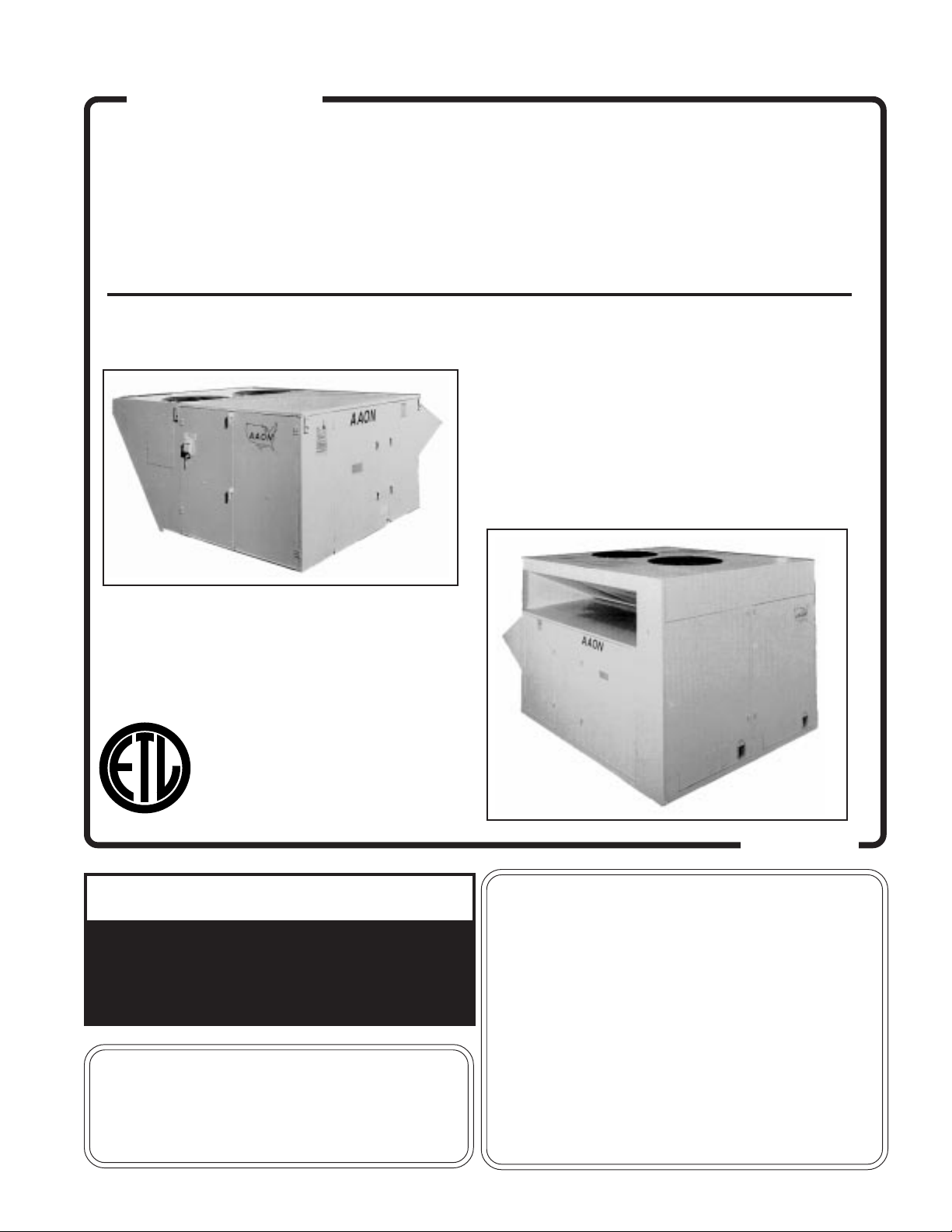
RK SERIES
HEATING • COOLING & COMBINATION
ROOFTOP UNITS
INSTALLATION
INSTRUCTION
MANUAL
LISTED
®
!
▲
If the information in this manual is not followed
exactly, a fire or explosion may result causing
property damage, personal injury or loss of life.
WARNING
FOR YOUR SAFETY
DO NOT STORE OR USE GASOLINE OR OTHER
FLAMMABLE VAPORS AND LIQUIDS IN THE
VICINITY OF THIS OR ANY OTHER APPLIANCE.
update 7-2000
FOR YOUR SAFETY
WHAT TO DO IF YOU SMELL GAS
• EXTINGUISH ANY OPEN FLAME.
• DO NOT TOUCH ANY ELECTRICAL SWITCH.
• DO NOT TRY TO LIGHT ANY APPLIANCE.
• DO NOT USE ANY PHONE IN YOUR BUILDING.
• IMMEDIATELY CALL YOUR GAS SUPPLIER FROM A
NEIGHBOR'S PHONE.
FOLLOW THE GAS SUPPLIER'S INSTRUCTIONS.
• IF YOU CANNOT REACH YOUR GAS SUPPLIER,
CALL THE FIRE DEPARTMENT.
1
Page 2
AAON
®
TABLE OF CONTENTS
SECTION PAGE NUMBER
GENERAL DESCRIPTION …………………………………………………………………………… 03
Unpacking
Certification
Codes and Ordinances
OWNER'S INFORMATION …………………………………………………………………………… 04
HEATING / COOLING SYSTEMS …………………………………………………………………… 05
INSTALLATION ………………………………………………………………………………………… 06
Setting the Curb / Unit ………………………………………………………………………… 07
Outside Air Hood ……………………………………………………………………………… 08
Electrical Info
Gas Piping Info ………………………………………………………………………………… 09
Service Clearances
Condensate Piping Info ……………………………………………………………………… 10
GAS UNIT LIGHTING INSTRUCTIONS …………………………………………………………… 11
PERIODIC INSPECTION PROCEDURES ………………………………………………………… 12
Gas Heating, Cooling, Electric, Steam, Hot Water & Chilled Water Units
SERVICE, TROUBLE SHOOTING & MAINTENANCE ………………………………………… 14
Lubrication
Cleaning
FILTER INSTALLATION / REPLACEMENT ……………………………………………………… 15
SERVICING ……………………………………………………………………………………………… 16
Rooftop Unit Replacement Parts …………………………………………………………… 18
SEQUENCE OF OPERATIONS ……………………………………………………………………… 19
Heating
Cooling
Optional Economizer
VAV Systems …………………………………………………………………………………… 20
Power Exhaust Options
COMPRESSOR CHECKOUT PROCEDURE ……………………………………………………… 21
IGNITION CONTROL CHECKOUT PROCEDURE ……………………………………………… 22
FACTORY START-UP FORM ………………………………………………………………………… 23
Owner should pay particular attention to the words: NOTE, CAUTION AND WARNING.
NOTES are intended to clarify or make the installation easier. CAUTIONS are given to prevent
equipment damage. WARNINGS are given to alert owner that personal injury and/or equipment
damage may result if installation procedure is not handled properly.
It is the intent of
AAON, Inc.
AAON, Inc.
reserves the right to change pricing, specifications and/or design of it's products without notice, obligation or liablity.
to provide accurate and current specification information. However, in the interest of product improvement,
© 2000
AAON
&
AAONAIRE
AAON, Inc.
, all rights reserved throughout the world.
are registered trademarks of
AAON, Inc.
, Tulsa, OK.
P83740 (rev. B • 7-00)
2
Page 3
The units are designed as self-contained heating, cooling
or combination units for outdoor installation only, using
the refrigerant shown on the rating plate, chilled water,
natural or propane gas, electric resistance, steam or hot
water.
UNPACKING
When received, the unit should be checked for damage
that might have occurred in transit. If damage is found,
it should be noted on the carrier's Freight Bill. A request
for inspection by carrier's agent should be made in
writing at once.
CERTIFICATION
• GAS HEAT MODELS
(a) Design Certified as a forced air furnace with or without cooling unit.
(b) Certified for outdoor installation only.
(c) Certified for installation on combustible roof with a minimum of 12" high curb.
(d) Certified with Heat Exchanger located downstream from Evaporator coil.
GENERAL DESCRIPTION
!
▲
Improper installation, adjustment, alteration, service or maintenance can cause property damage,
personal injury or loss of life. Installation and
service must be performed by a qualified installer, service agency or the gas supplier.
NOTE: These units must not be used as a "construction heater" at any time during any phase of construction. Very low return air temperatures, harmful vapors, and misplacement of the filters will damage the
unit and its efficiency.
WARNING
• STEAM OR HOT WATER HEAT MODELS
(a) Certified as a forced air furnace with or without cooling unit.
(b) Certified for outdoor installation only.
(c) Certified for installation on combustible roof with a minimum of 12" high curb.
(d) ARI certified coils.
• ELECTRIC HEAT MODELS
(a) Certified as an electric warm air furnace with or without cooling unit.
(b) Certified for outdoor installation only.
(c) Certified for installation on combustible roof with a minimum of 12" high curb.
• COOLING MODELS
(a) Certified as a commercial central air-conditioner with or without electrically operated compressor.
(b) Certified for outdoor installation only.
(c) Certified for installation on combustible roof with a minimum of 12" high curb.
(d) ARI certified coils.
CODES AND ORDINANCES
System should be sized in accordance with National
Warm Air Heating and Air Conditioning Association
Literature, or the Guide of American Society of Heating,
Refrigeration and Air Conditioning Engineers. The
installation must conform with local building codes or, in
the absence of local codes with (United States) National
Fuel Gas Code "ANSI-Z223.1", (Canada) current CAN /
CGA- B149.1 or . 2. Installation Codes for Gas Burning
Appliances and Equipment, current C.S.A. Standard
C22.1, Canadian Electrical Code Part 1, and C.S.A.
Standard B52 Mechanical Refrigeration Code, and Local
Plumbing or Waste Water Codes.
! IMPORTANT
▲
The Clean Air Act of 1990 bans the intentional
venting of refrigerant (CFC's and HCFC's) as of
July 1, 1992. Approved methods of recovery,
recycling or reclaiming must be followed. Fines
and/or incarceration may be levied for noncompliance.
3
Page 4
OWNER'S INFORMATION
WARNING
Failure to observe the following instructions will result
in premature failure of your system, and possible voiding of the warranty.
DIRECT EXPANSION (DX) COOLING UNITS
Never cut off the main power supply to the unit, except
for complete shutdown. When power is cut off from the
unit, any compressors using crankcase heaters cannot
prevent refrigerant migration. This means the compressor will cool down, and liquid refrigerant will accumulate in the compressor. Since the compressor is designed
to pump refrigerant gas, damage may occur when power
is restored.
If power must be cut off for more than an hour, turn the
thermostat system switch to "OFF", and leave it off until
the main power switch has been turned on again for at
least twenty four hours for units with compressor crankcase heaters. This will give the crankcase heater time to
clear any liquid accumulation out of the compressor
before it is required to run.
Always control the system from the thermostat, or control panel, never at the main power supply (except for
emergency or for complete shutdown of the system).
During the cooling season, if the air flow is reduced due
to dirty air filters or any other reason, the cooling coils
will get too cold and will cause excessive liquid to return
to the compressor. As the liquid concentration builds up,
oil is washed out of the compressor, leaving it starved for
lubrication.
THE COMPRESSOR LIFE WILL BE SERIOUSLY
SHORTENED BY THIS REDUCED LUBRICATION,
AND THE PUMPING OF EXCESSIVE AMOUNTS OF
LIQUID OIL AND REFRIGERANT.
GAS OR ELECTRIC HEATING
The system is designed to cool or heat a given amount of
air each minute it operates. If this amount of air is
greatly reduced (approximately 1/3 during the heating
season), the heat exchanger / heater coil will overheat,
and may cut the burner / heater off entirely by action of
the safety high temperature limit device which is incorporated in the exchanger or heating area.
GAS HEAT UNITS - Should overheating occur, or the
gas supply fail to shut off; shut off the manual gas valve
to the furnace before shutting off the electrical supply.
PROLONGED OVERHEATING OF THE HEAT
EXCHANGER WILL SHORTEN ITS LIFE.
Improper installation, adjustment, alteration, service or
maintenance can cause property damage, personal injury or loss of life. Installation and service must be
performed by a qualified installer, service agency or if
gas fired units, the gas supplier. Refer to installation
instructions provided with the unit and this manual.
CAUTION: While the following incorrect operations
may not cause damage to the system, they will impair
the performance, and may cause the built-in safety
devices to cut the system off completely.
1. LOW AMBIENT OPERATION
The cooling section of a direct expansion (DX)
unit will not operate properly when the outdoor
temperature is below 55° degrees. Outside air
intake options are recommended if operation
below 55° degrees is expected.
2. MULTIPLE UNIT OPERATION
When several units are used in conditioning the
space, and part or all of them are combination
heating-cooling units, all systems thermostat
switches must be set at either heating or cooling
(or set at "off"). Do not leave part of the systems
switched to the opposite mode. All cooling only
units should be switched to "off" at the thermostat during the heating season.
WIRING DIAGRAMS
A complete set of unit specific wiring diagrams in both
ladder and point-to-point form are laminated in plastic
and located inside the control compartment door.
CONDENSATE PIPING
The unit requires a drain trap to be connected to the
drainpan at the unit. If codes require a condensate drain
line, the line should be the same pipe size as the drain
nipple and should pitch downward toward drain.
The condensate drain pipe ("P" trap) is factory supplied
and is shipped loose in the control access compartment
for field installation. An air break should be used with
long runs of condensate lines.
!
▲
WARNING
Scroll compressors will be damaged by
operation with the wrong rotation.
THE LOW PRESSURE SWITCH HAS BEEN
DISCONNECTED AFTER TESTING
AT THE FACTORY.
The wiring must be reconnected and proper
rotation determined at the time of start-up by
a qualified service technician using suction
and discharge pressures gauges.
Any alteration should only be made at
the unit power connection.
4
Page 5

HEATING & COOLING SYSTEMS
NORMAL OPERATION
HEATING
Set the thermostat system switch to "HEAT".
Set the thermostat fan switch to "AUTO" or "ON".
Set the thermostat temperature at the desired point.
COOLING
Set the thermostat system switch to "COOL".
Set the thermostat fan switch to "AUTO" or "ON".
Set the thermostat temperature at the desired point.
AIR CIRCULATION
Set the thermostat system switch to "OFF".
Set the thermostat fan switch to "ON".
Do not change temperature setting.
With these settings, the air circulating blower will run
continuously but the air will not be heated or cooled.
SYSTEM OFF
Set the thermostat system switch to "OFF".
Set the thermostat fan switch to "AUTO".
Do not change temperature setting.
With these settings, the system is shut down, with the
exception of the control system power (24 volts), and the
crankcase heater of the compressor (about 60 watts).
DO NOT TURN OFF THE MAIN POWER SWITCH.
NIGHT AND VACANT WEEKEND OPERATION
If it is desired to reduce the operating time during the
night, and during periods when the space is unused,
it is recommended that the temperature setting be
raised about five degrees during these periods of the
cooling season, and lowered about ten degrees during
the heating season.
GAS HEATING SYSTEM
The heating section is for use with natural gas supply
pressure of 6" to 10.5" Water Column. The unit can also
be fired on propane gas with a supply pressure to the
valve of 11" to 12" Water Column. A 1/8" pressure tap
must be supplied by the installer in the piping just ahead
of the gas valve. The rating plate on the furnace shall be
inspected to make sure that the unit is stamped for the
proper gas. The pressure tap on the outlet end of the gas
valve should be removed and the valve adjusted for the
proper manifold pressure to 3.5" on natural gas and
10.5" for propane gas.
The burner area is not sealed and combustion air is
supplied by a centrifugal blower which draws in fresh air
through a protected opening. This air is introduced into
the burner tubes by the action of the induced draft
blower. This insures an even flow of primary and secondary air to the burners.
The heating system and safety controls are 100% tested
on each unit before it leaves the factory.
INSTALLATION IS TO BE ADJUSTED
TO OBTAIN AN AIR TEMPERATURE RISE
WITHIN THE RANGE SPECIFIED ON THE
RATING PLATE.
The units are equipped with a direct spark ignition
system which proves the burner operation during each
call for heat.
Power to the ignition control is 24 volts to reduce hazards. Burner ignition is by a high intensity spark.
When heat is called for, the cooling system is inoperable
except for the indoor blower motor. Actual heating is
accomplished by firing gas into the heat exchanger
assembly.
ELECTRIC HEATING SYSTEM
Heating is accomplished by passing electrical current
through a specified amount of resistance heaters which
will produce the required heat. The indoor blower motor
will energize at the same time as the heaters.
STEAM OR HOT WATER HEATING SYSTEM
Heating is accomplished by passing steam or hot water
through the steam or hot water coil assembly.
COOLING SECTION • DX
All direct expansion refrigeration systems are factory
assembled, charged with refrigerant, tested and operated. On all units 8 ton and larger the refrigerant system
includes multiple circuit evaporator and condenser coils
providing two or more stages of cooling. These systems
are provided with liquid line filter driers, expansion
valves and fully hermetic compressors. Compressors are
equipped with a positive pressure forced lubrication
system. The air cooled condenser coil(s) is constructed of
copper tubes with aluminum fins, the air is pulled
through with propeller fans. The evaporator coil is draw
through, made of copper tubes with aluminum fins.
The refrigeration section of these appliances has been
found acceptable with applicable provisions of "ANSI /
UL 1995" and current "C.S.A. Standard C22.2" by E.T.L.
NOTE: Crankcase Heater Operation
Some units are equipped with a compressor crankcase
heater, which should be energized at least 24 hours prior
to setting the thermostat for cooling operation.
COOLING SECTION • CHILLED WATER
or NON-COMPRESSORIZED UNIT
Chilled water or non-compressorized units have factory
installed coils. These systems are provided with internal
header connections for field connection. Coils are aluminum fin / copper tube construction.
5
Page 6
INSTALLATION
12
12
12
12
12
12
12
12
12
12
12
12
12
12
!
▲
CAUTION
!
▲
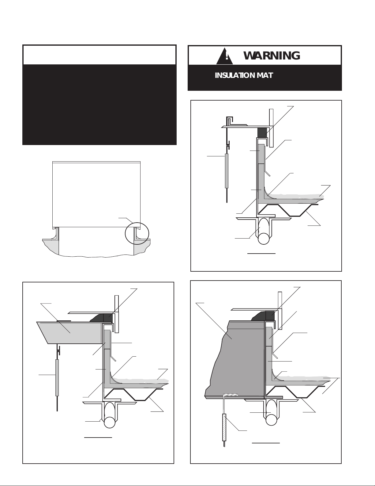
WARNING
If outside air is in contact with the bottom
of the unit, the unit must have the bottom
insulation option or be field insulated.
DO NOT DRILL OR PUNCH HOLES IN BASE
OF UNIT FROM INSIDE THE UNIT OR FROM
BELOW TO ATTACH DUCTWORK. LEAKING
MAY OCCUR IF UNIT BASE IS PUNCTURED.
SEE DETAIL "A"
SECTIONAL VIEW OF UNIT ON ROOF CURB
INSULATION MATERIALS MAY
DUCT /
FLEX
CONNECTOR*
STRUCTURAL
STEEL *
BE COMBUSTIBLE
GASKET
COUNTER
FLASHING *
WOOD
NAILER *
CANT STRIP *
RIGID
INSULATION *
CURB
ROOF
DECK *
DETAIL 'A'
DUCT / UNIT CONNECTION
* FIELD SUPPLIED
ROOFING
MATERIAL*
GASKET
WOOD
NAILER *
COUNTER
FLASHING *
RIGID
INSULATION *
CANT STRIP *
ROOFING
MATERIAL*
ROOF
DECK *
DUCT /
FLEX
CONNECTOR*
DUCT RAIL
CURB
STRUCTURAL
STEEL *
WOOD
NAILER *
RIGID
INSULATION *
GASKET
COUNTER
FLASHING *
CANT STRIP *
ROOFING
MATERIAL*
ROOF
DECK *
SOLIDBOTTOM
ACOUSTIC CURB
STRUCTURAL
STEEL *
DUCT / FLEX CONNECTOR*
DETAIL 'A'
OPEN BOTTOM CURB
DUCT RAIL CONNECTION
* FIELD SUPPLIED
6
DETAIL 'A'
ACOUSTIC CURB
* FIELD SUPPLIED
Page 7
INSTALLATION continued
AAON Rooftop units are designed for fast, easy installation. The curb is mounted first and must be located so
that duct connections will be clear of structural members of the building.
SETTING THE CURB
When using the factory curb, make openings in roof
decking large enough to allow for duct penetrations and
workspace only. Do not make openings larger than
necessary. Set the curb to coincide with the openings.
Make sure the curb is level.
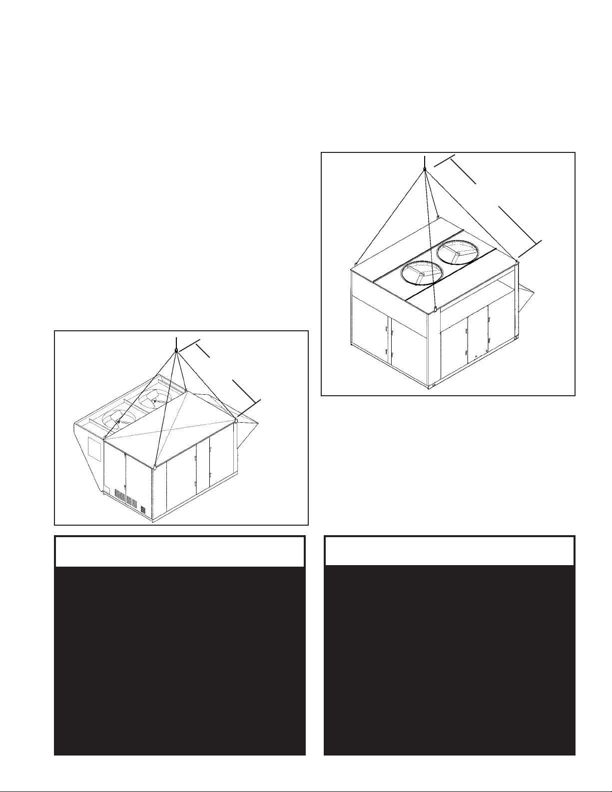
SETTING THE UNIT
If cables or chains are used to hoist the unit they must be
the same length and care should be taken to prevent
damage to the cabinet / coils or condenser fans.
It is recommended lifting the unit with the outside air
hood in the downward shipping position, however the
unit may be lifted with the outside air hood in the open
position.
Before lifting unit, be sure that all shipping material has
been removed from unit. Secure hooks and cables at all
lifting points / lugs provided on the unit.
Hoist unit to a point directly above the curb and duct
openings. Lower unit while guiding the unit to align with
utility opening and duct openings. Be sure that the
gasket material has been applied to curb. Continue lowering the unit until the unit skirt fits around the curb.
Make sure the unit is properly seated on the curb and is
level.
180" minimum
length
99" minimum
length
LIFTING DETAIL
TYPICAL FOR
2 - 25 TON UNITS
!
▲
WARNING
Improper installation, adjustment,
alteration, service or maintenance can
cause property damage, personal injury
or loss of life. Installation and service must
be performed by a qualified installer,
service agency or the gas supplier.
Install the gas fired unit to assure the flow
of combustion and ventilating air is not
obstructed from reaching the heater and
that the flue outlet is located at least
120 inches away from any opening
through which combustion products
could enter the building.
LIFTING DETAIL
TYPICAL FOR
26 - 60 TON UNITS
The unit shall be installed so that the rectangular flue (if
applicable) is located at least 120" away from any opening through which combustion products could enter the
building. The unit shall also be installed so that the flow
of combustion and ventilating air is not obstructed from
reaching the furnace. Do not position flue opening to
discharge into a fresh air intake of any other piece of
equipment.
!
▲
CAUTION
Where the supply or warm air duct passes
through a combustible roof, a clearance
of one inch must be maintained between
the outside edges of the duct and
combustible material in accordance
with National Fire Protection Association
Standard No. 90A. Provide flashings or
enclosure between structure and roof
and all joints must be sealed with mastic
roofing to ensure a watertight seal.
All roofing work should be performed by
competent roofing contractors to avoid
any possible leakage.
7
Page 8
INSTALLATION continued
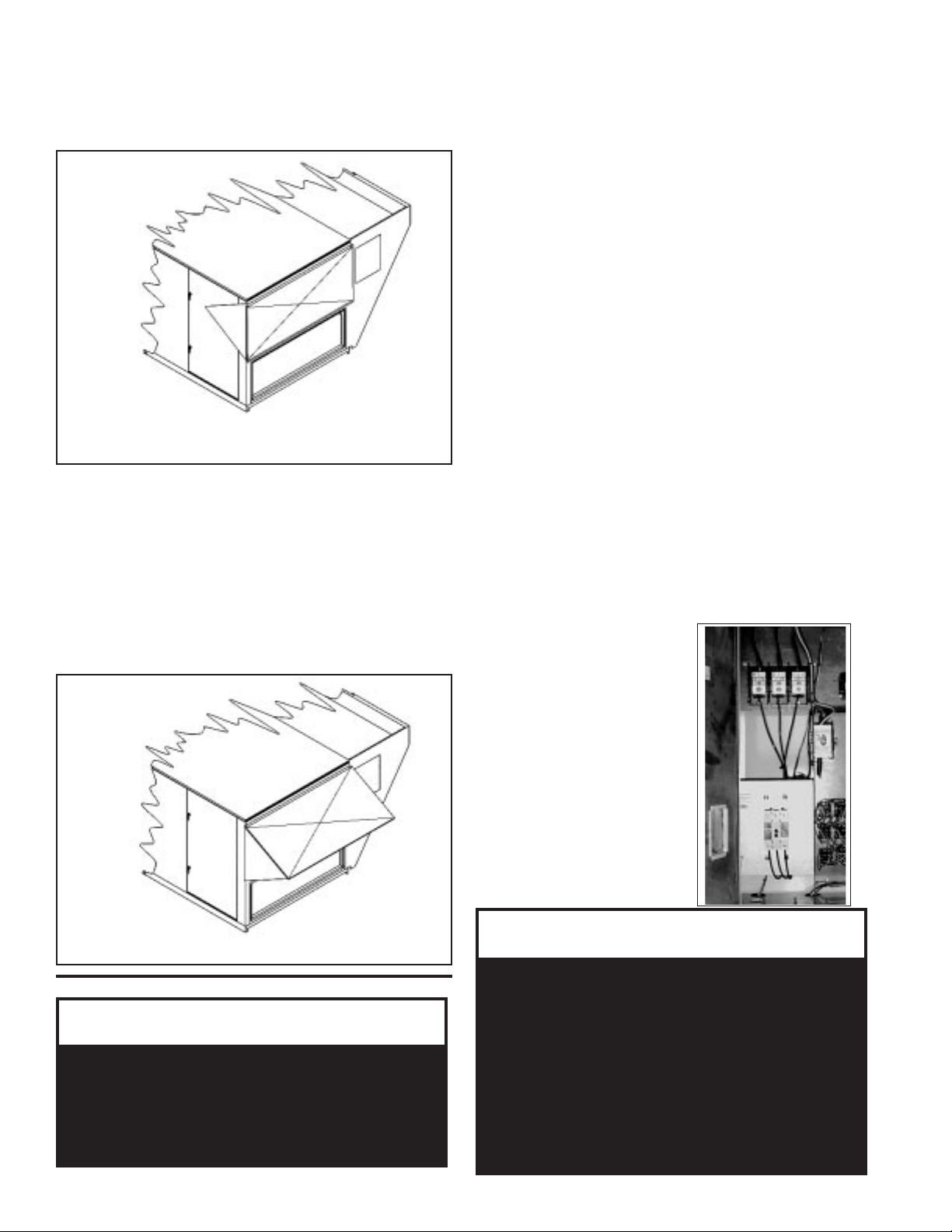
OUTSIDE AIR HOOD
For proper unit operation, the air hood must be opened at
start-up as shown below:
AIR HOOD SHOWN IN THE SHIPPING POSITION
(CLOSED)
ELECTRICAL
Check the unit data plate voltage to make sure it agrees
with the power supply. Connect power to the unit
according to the wiring diagram provided with the unit.
The power and control wiring may be brought up through
the utility entry. Protect the branch circuit in accordance with code requirements. Control wires should not
be run inside the same conduit. The unit must be
electrically grounded in accordance with the current
National Electric Code, ANSI / NFPA No. 70. In Canada
use current C.S.A. Standard C22.1 Canadian Electric
Code Part 1.
Power wiring is to the unit terminal block or main
disconnect. All wiring beyond this point has been done
by the manufacturer and cannot be modified without
effecting the unit's agency / safety certification.
AIRFLOW IS TO BE ADJUSTED AFTER INSTALLATION TO OBTAIN AN AIR TEMPERATURE RISE
WITHIN THE RANGE SPECIFIED ON THE RATING
PLATE.
Remove shipping screws from each side of the hood in the
"closed" postion. Lift hood to the "open" position, seal
flange and secure with sheet metal screws.
Air hoods may vary according to unit size and options.
The illustration shown is for practical guidelines for all
outside air hoods.
Outdoor air intake adjustments should be made according building ventilation or local code requirements.
DUE TO JOB SPECIFICATION REVISIONS, IT MAY
BE NECESSARY TO ADJUST OR CHANGE THE
SHEAVE OR PULLEY TO OBTAIN THE DESIRED
AIRFLOW AT THE TIME OF INSTALLATION.
START-UP TECHNICIAN MUST CHECK BLOWER
MOTOR AMPERAGE TO ENSURE THAT THE AMPERAGE LISTED ON THE MOTOR NAMEPLATE IS
NOT EXCEEDED.
NOTE: All units are factory
wired for 208 / 230, 460 or
575 volt. If unit is to be
connected to a 208v supply,
the transformer must be
rewired for 208v service.
For 208v service interchange
the yellow and red conductor
on the low voltage control
transformer.
RED - BLK 208 volt ;
YEL - BLK 230 volt.
AIR HOOD SHOWN IN THE OPEN POSITION
!
▲
Electric shock hazard. Can cause injury or death.
Before attempting to perform any service or
maintenance, turn the electrical power to unit to
OFF at disconnect switch(es). Unit may have
multiple power supplies.
W ARNING
! CAUTION
▲
On three phase units the rototation must be
checked on ALL MOTORS AND COMPRESSORS.
SCROLL COMPRESSORS ARE DIRECTIONAL.
Rotation must be checked on start-up by a
qualified service technician using
suction and discharge gauges.
Scroll compressors will FAIL if run in the wrong
direction. Blower and condenser rotation
should be checked and only be altered if
necessary at the power connection.
8
Page 9

SERVICE CLEARANCES
LOCATION
Return Air (Back)
Vent Side (Front)
Left Side
Right Side
Top UNOBSTRUCTED
GAS PIPING
Size gas piping to supply the unit with 6" to 10.5" water
column pressure for natural gas or 11" water column
pressure for propane when all gas consuming devices in
the building connected to the same gas system are
operating. Install piping in accordance with local codes,
the piping must conform with the latest ANSI-Z223.1
National Fuel Gas Code; in Canada, Current Standard
CAN / CGA-B149, Installation Codes for Gas Burning
Appliances and Equipment.
Some utility companies will require pipe sizes larger
than the minimum sizes listed.
2 - 7
36"
48"
6"
48"
UNIT SIZE
8 - 15
48"
48"
6"
60"
16 - 25 26 - 60
48"
48"
6"
60"
60"
48"
60"
60"
GAS PIPING SIZES
UNIT SIZE / TONS
02 - 03 69 3/4"
04 90 3/4"
05 - 06 - 07 90 - 180 3/4"
08 - 10 180 - 270 - 351 3/4"
13 - 15 180 - 270 - 390 3/4"
16 - 20 - 25 270 - 390 - 480 3/4"
26 -30 -40 -50 -60 540 - 780 (2) 3/4"
NOTE: Codes may require the use of a manual main
gas shut-off valve and union, (furnished by others)
installed in the gas line external to the unit.
INPUT / MBH
PIPE SIZE
INSTALLATION continued
!
CAUTION
Some soaps used for leak detection are
corrosive to certain metals. Carefully
rinse piping thoroughly after leak
test has been completed.
The furnace must be isolated by closing the manual shut
off valve or disconnected from the gas supply piping
during pressure testing of the piping system with pressures in excess of 1/2 PSIG.
The flow of combustion and ventilating air shall not be
blocked or otherwise obstructed in any way.
NOTE: All gas-fired heat exchangers are completely
tested at the factory before shipment. This will remove
nearly all of the oils that have been used in the manufacturing process, however, trace amounts may remain.
When performing the initial start-up at the jobsite, it is
highly recommended that people or any other living
animals, that may be sensitive to the residual odors or
gases, NOT be present in the conditioned space during
the start-up. In all cases, including the initial factory
firing and testing, any of the gases will be under the
acceptable level of concentration for human occupancy.
!
WARNING
Those sensitive to odors or gases from trace
amounts of residual oils should NOT be present
in the conditioned space during the start-up
of a gas-fired installation.
GAS PIPING is to be supported DIRECTLY AT CONNECTION TO UNIT and must not be strained or bent
and shall be supported by metal straps, blocks or hooks
at intervals not to exceed that shown in the following
table:
GAS PIPING SUPPORT
SIZE OF PIPE
1/2" 6'
3/4" or 1" 8'
1 1/4" or larger (horizontal) 10'
1 1/4" or larger (vertical) every floor level
Pipe joint compounds used on all gas piping connections
shall be resistant to the action of petroleum gases.
An 1/8" NPT plugged tap is required immediately ahead
of the unit gas control valve.
All piping connections shall be checked with a soap
solution for gas leaks before operating the appliance.
INTERVALS (feet)
After electrical power is turned on, set unit controls for
heating, and check for operation.
When checking burner operation, flames should be
observed as blue with slight or no yellow tipping. There
should be no sign of flames floating or lifting off or away
from the main burners.
NOTE: In case emergency shut down is required, turn
off the main manual gas shut-off valve and disconnect
main electrical power to unit. These devices should be
properly labeled by the installer.
!
WARNING
DO NOT USE OPEN FLAME OR OTHER SOURCE
OF IGNITION FOR LEAK TESTING.
When pressure testing the gas supply piping, the
furnace must be isolated or disconnected by
closing the individual manual shut-off valve from
the gas supply. Gas valves can be damaged if
subjected to more than 0.5 psig pressure.
9
Page 10

INSTALLATION continued
GAS PIPING CAPACITIES
Nominal
Iron Pipe
Size, Inches
3/4" 278 115 79 55
1" 520 215 150 100
1 1/4" 1050 440 305 210
1 1/2" 1600 670 460 320
2 3050 1270 870 610
2 1/2" 4800 2000 1400 980
*At gas pressure of 0.5 PSIG or less and a pressure
drop of 0.5 inches of water. Specific gravity = 0.60.
Gas
Shut-off
Valve*
*Gas piping field installed by others
Gas piping information is typical for one gas valve. For
units with dual heat exchangers, duplicate gas piping to
number two gas valve.
Max. Capacity of Gas Pipe in Cubic Ft. Per Hour*
LENGTH OF PIPE, FEET
10 50 100 200
Utility
Access
Union*
Heat
Exchanger
Gas
Valve
GAS PIPING ILLUSTRATION
In compliance with the ANSI Standard, installations
exceeding 2-psi or less than 5-psi nominal require a
tested and approved over-pressure protection device for
use with the regulator.
For proper heater operation, pressure to the regulator
MUST NOT BE greater than 5-psi.
CONDENSATE PIPING
The RK equipment is furnished with drain connections
and 'P' traps are furnished with the equipment in the
same quantity as the drain connections. On the 'A', 'B'
and 'C' cabinet models (2 - 25 ton) require one drain
connection. On the 'D' cabinet models (26 - 60 ton) all 3
of the drain connections must be used and individually
trapped to ensure a minimum amount of condensate will
be present in the drain pans.
Drainage of condensate directly onto the roof may be
acceptable in certain areas, refer to applicable codes. If
condensate is to drain directly onto the roof, a small drip
pad should be placed below the drain to protect the roof
from possible damage.
When condensate is piped into the building drainage
system, the drain pipe should penetrate the roof external to the unit itself. The drain line should be pitched
away from the unit at least 1/8 inch per foot. On longer
runs, an air break should be used to ensure proper
drainage.
Drain pans in any air conditioning equipment, even
when they have a built-in slope to the drain, will have
moisture present and will require periodic cleaning to
prevent any build up of algae of bacteria. Cleaning of the
drain pans will also prevent any possible plugging of the
drain lines and an overflow of the pan itself. All cleaning
of the drain pans and inside of the equipment should be
done by qualified personnel.
FOR PROPER UNIT OPERATION,
DRAIN TRAP MUST BE INSTALLED AS SHOWN.
USE ABS TYPE CEMENT TO JOIN THE CONNECTIONS.
2 to 25 ton Models Require (1) Connection.
26 to 60 ton Models Require (3) Connections.
Optional
Gas Pressure Regulator
GAS PRESSURE REGULATOR & OVER-PRESSURE
PROTECTION DEVICE
On applications where gas service to the unit is greater
than 10.5"w.c. and less than 2-psi, a gas pressure regulator must be installed.
At supply pressures in excess of 2-psi and less than 5psi, ANSI Z21.80 line regulator standard requires a
means (an over-pressure protection device / OPD) to
limit the downstream pressure to 2-psi maximum, in the
event of regulator failure.
Typical 'P' trap
connection
10
Page 11

GAS UNIT LIGHTING INSTRUCTIONS
FOR YOUR SAFETY READ BEFORE OPERATING
WARNING: IF YOU DO NOT FOLLOW THESE INSTRUCTIONS EXACTLY, A FIRE OR EXPLOSION MAY
RESULT CAUSING PROPERTY DAMAGE, PERSONAL INJURY OR LOSS OF LIFE.
A. This appliance does not have a pilot. It is equipped with an
ignition device which automatically lights the burner.
not try to light the pilot by hand.
Do
B. BEFORE OPERATING smell all around the appliance area
for gas. Be sure to smell next to the floor because some gas
is heavier than air and will settle on the floor.
WHAT TO DO IF YOU SMELL GAS
• Do not try to light any appliance.
• Do not touch any electric switch; do not use any phone
in your building.
• Immediately call your gas supplier from a neighbor's phone.
Follow the gas supplier's instructions.
OPERATING INSTRUCTIONS
1. STOP! Read the safety information above this label.
2. Set the thermostat to lowest setting.
3. Turn off all electric power to the appliance.
4. This appliance is equipped with an ignition device which
automatically lights the burner. Do
hand.
GAS CONTROL KNOB
SHOWN IN "ON"
POSITION
GAS INLET
not try to light the pilot by
ON
OFF
• If you cannot reach your gas supplier, call the fire department.
C. Use only your hand to push in or turn the gas control knob.
Never use tools. If the knob will not push in or turn by hand,
don't try to repair it, call a qualified service technician. Force
or attempted repair may result in a fire or explosion.
D. Do not use this appliance if any part has been under water.
Immediately call a qualified service technician to inspect the
appliance and to replace any part of the control system and
any gas control which has been under water.
5. Open control access panel.
6. Push in gas control knob slightly and turn clockwise to "OFF".
NOTE: Knob cannot be turned to "OFF" unless knob is pushed
in slightly. Do not force.
7. WAIT five (5) minutes to clear out any gas. Then smell for gas, including
near the floor. If you smell gas, STOP! Follow "B" in the safety
information above on this label. If you don't smell gas, go to the next step.
8. Turn gas control knob counterclockwise to "ON".
9. Close control access panel.
10. Turn on all electric power to the appliance.
11. Set thermostat to desired setting.
12. If the appliance will not operate, follow the instructions
"To Turn Off Gas To Appliance" and call your service
technician or gas supplier.
TO TURN OFF GAS TO APPLIANCE
1. Set the thermostat to lowest setting.
2. Turn off all electric power to the appliance if service
is to be performed.
3. Open control access panel.
4. Push in gas control knob slightly and turn clockwise to
"OFF". Do not force.
5. Close control access panel.
11
Page 12

PERIODIC INSPECTION PROCEDURES
GAS HEATING UNITS
1. The flow of combustion and ventilating air shall
not be blocked or otherwise obstructed in any way.
The indoor blower, evaporator coil and filters should be
inspected monthly.
2. Once each year, before unit is turned on for the
heating season, a qualified serviceman should inspect
all flue product carrying areas of the furnace and main
burners for continued safe operation.
WARNING: At least once each year, a qualified serviceman should check out all of the items listed under
the servicing and trouble shooting and maintenance
section of this manual.
3. If the induced draft blower/motor assembly has
to be replaced, care must be taken to provide an airtight seal between the blower housing and the burner
box. High temperature silicone sealant must be used to
ensure a good seal.
4. GAS BURNERS
THE BURNERS SHOULD NEVER REQUIRE CLEANING. If cleaning becomes necessary, it indicates faulty
operation of the unit. The cleaning should only be done
by a qualified service agency and only after consultation
with an AAON Service Representative.
It is recommended that if the gas burners require cleaning,
call an AAON Service Engineer at (918) 583-2266.
5. HEAT EXCHANGER
The necessity for cleaning the exchanger could indicate
faulty operation and should only be checked by a qualified service agency and only after they have discussed
the problem with a Service Representative.
Heat Exchanger prior to installation in unit.
Note dimple construction.
Manifold
Burner
Horn (typ)
Spark Rod
Flame Sensor
Burner Assembly
12
Combustion Motor
Flue Outlet
Page 13

PERIODIC INSPECTION PROCEDURES Continued
COOLING
1.
2. Set thermostat in cooling mode and place the
"fan" switch to on. Check blower for correct operating
direction, amperage and voltage.
3. PACKAGED UNITS - Check compressor(s)
operation. Check the amperage and compare to the
nameplate data (check amperage load side of the compressor contactor).
4. DX COIL UNITS - If applicable check remote
condenser as per the manufacturer's recommendations.
5. CHILLED WATER UNITS - Check remote chiller
operations as per the manufacturers instructions.
Check coolant flow valves for correct operation and
settings.
HEATING • NATURAL GAS
1. Before turning on the main electrical power
switch, be sure that all gas supply lines have been
purged of air.
2. Turn gas valve to "ON" position.
3. Turn main electrical power switch to "ON" and
set the thermostat to call for heat. The vent motor
should operate. The control will automatically supply
energy to the spark gap and the gas valve after the
thermostat contact closes.
Main Power Switches are on and power is to the unit.
HEATING • ELECTRIC
1. Set thermostat in the heat mode.
2. Set thermostat to call for heat to engage all
electric heat strips. Check blower for proper rotation
and voltage.
3. Measure the amperage and voltage. Compare
them to the nameplate data.
HEATING • STEAM OR HOT WATER
1. Set thermostat in the heat mode.
2. Observe supply blower for proper rotation and
voltage.
3. Check boiler or hot water operations according
to the manufacturers instructions.
4. Check control flow valves for correct operation
and settings per manufacturers instructions.
NOTE:
Should any of the above functions not perform properly,
the following sequence of operations are given for the
various heating and cooling modes with various control
systems for an additional analysis in the case of any
problems.
ELECTRIC, STEAM, HOT WATER, COOLING &
CHILLED WATER UNITS
4. The sensing probe detects the presence of the
flame. (Should no flame be detected in 10 seconds, the
ignition system will recycle. If no flame is detected in 3
tries, the ignition system will lockout.)
5. Adjust thermostat to a low temperature setting
to open contacts. The main gas flames should be extinguished.
NOTE: The evaporator blower is controlled by the
ignition system. In the fan "Auto" mode the blower
comes on 45 seconds after flame is proved and goes off
120 seconds after the thermostat opens.
1. Indoor blower, coils and filters should be inspected monthly.
2. Once each year, before unit is turned on for the
heating season, a qualified serviceman should inspect
the unit for proper operation.
3. Inspect all valves and steam traps in accordance with manufacturers recommendations.
WARNING: All of the items listed under the service,
trouble shooting and maintenance section of this manual
should be performed once a year.
!
▲
CAUTION
Before leaving installation, a complete
operating cycle should be observed
to verify that all components
are functioning properly.
13
Page 14

SERVICING, TROUBLE SHOOTING & MAINTENANCE
LUBRICATION
All original blower motors and bearings are furnished
with an orginal factory charge of lubrication. Some
applications will require that bearings be re-lubricated
periodically. The schedule will depend on the operating
duty, temperature variations or other severe atmospheric
conditions.
Electric shock hazard. Shut off all electrical power
to unit to avoid shock hazard or injury from rotating
parts.
!
▲
W ARNING
Bearings should be re-lubricated when at normal operating temperatures, but not running. Rotate the fan
shaft by hand and add only enough grease to purge the
seals. DO NOT OVERLUBRICATE.
Recommended greases are:
SHELL OIL - DOLIUM R
CHEVRON OIL - SRI No. 2
TEXACO INC. - PREMIUM RB
SERVICE
In the event the unit is not functioning correctly and a
service company is required, a company with service
technicians qualified and experienced in both gas, electric heating and air conditioning be permitted to service
the systems in order to keep warranties in effect. The
service tech may call the factory if assistance is required.
BEFORE CALLING, HE SHOULD HAVE THE MODEL
AND SERIAL NUMBER OF THE UNIT AVAILABLE
FOR THE CUSTOMER SERVICE DEPARTMENT TO
HELP ANSWER QUESTIONS REGARDING THE
UNIT.
CLEANING
Inspect unit interior at the beginning of each heating
and cooling season and as operating conditions require.
COILS
Evaporator coil(s) should be inspected and cleaned annually to ensure there is no obstruction to air flow.
Condenser coil(s) should be inspected monthly. Clean
condenser coils annually and as required by location or
outdoor air conditions.
CONDENSATE DRAIN
Check and clean each year at start of cooling season.
BLOWER
Inspect blower and blower section to keep free of dust or
debris. TURN OFF POWER BEFORE ATTEMPTING
TO CLEAN BLOWER WHEEL.
Typical slide-out blower section
AAON, Inc.
Phone: 918-583-2266
Fax: 918-382-6364
Customer Service Department
COMMON CAUSES OF REDUCED AIR FLOW
A. DIRTY FILTERS - Filters must be inspected and
replaced on a regular basis. It is strongly recommended
that the media be replaced monthly. Clean filters are
your best insurance against premature system
breakdown.
Do not permit the unit to be operated unless the filters
are in place. Operation of the unit without filters will
result in a clogged evaporator coil - a very expensive
service job to correct.
B. OBSTRUCTION TO AIR FLOW - Supply and
return air grilles must be kept clear so air can be freely
discharged and drawn from the system.
14
Page 15

FILTER INSTALLATION / REPLACEMENT
Open filter access door. Slide filters towards you and inspect. Replace old filters with the size indicated on each
filter or as shown in the filter chart below. Be sure arrow points towards the blower.
(Filters should be checked every 30 days and replaced or cleaned as necessary).
IT IS IMPORTANT TO KEEP COILS, BLOWER AND FILTERS CLEAN !
Slide-out
filters
Optional
Economizer
Optional R/A
smoke detector
location
NOTE: CHART REFLECTS STANDARD FACTORY SUPPLIED FILTERS AND SIZES.
CONTACT FACTORY FOR SPECIAL OPTIONAL FILTER PACKAGES.
FILTERS
6
2
UNIT SIZE
13 & 15
6
3
16 - 25
26 - 40 50 & 60
2
41012
FILTER SIZE
(Type)
16" x 20"
Throwaway (Qty)
16" x 20"
Pleated (Qty)
16" x 25"
Pleated (Qty)
20" x 25"
Pleated (Qty)
20" x 32"
Replaceable Media
24" x 40"
Replaceable Media
17" x 47"
Replaceable Media
FILTERS SHOULD BE REPLACED EVERY 30 DAYS OR AS REQUIRED.
2 - 5
4
2
6 & 7
4
2
8 & 10
15
Page 16

SERVICING
TROUBLE
ELECTRIC HEATING
SYSTEM OFF
EVAPORATOR MOTOR WILL NOT RUN
BLOWER DOESN'T DELIVER AIR
BLOWER COMES ON, BUT LITTLE OR NO
HEAT
SYSTEM OFF
POSSIBLE CAUSE
1. Check power at line side of contactor(s).
2. Thermostat not set for heating.
1. Overload relay tripped.
2. Heater Relay not energized.
3. Blower Contactor not energized.
4. Capacitor shorted or open (PSC motors only).
1. Blower running backwards.
2. Dirty air filters.
3. Dirty coils.
4. Duct obstruction.
5. Belts loose.
1. One or more heater contactors are open.
2. Limit switches are open.
3. Heater relay open.
4. Heat strips burned out.
GAS HEATING
1. Check power and gas supply.
2. Check thermostat switches and settings.
3. Check 24 volt power to ignition control.
BURNER WON'T COME ON
COMBUSTION AIR BLOWER WON'T RUN
BURNER GOES "OFF" ON HIGH LIMIT
IGNITION ON, BURNER WON'T LIGHT
1. Check for power at main gas valve.
2. Defective gas valve.
3. Loose or broken connection to gas valve.
4. Check limit controls for open.
5. Check continuity of differential pressure switch with motor
turning. If open, replace differential pressure switch.
6. Defective ignition control.
1. Thermostat not calling for heat.
2. Relay not closing. (No power to motor)
3. Motor stuck or winding open.
4. Internal motor overload open.
1. Unit blower not coming on. (Check fan control)
2. Blower motor running backward.
3. Filters dirty.
4. Ducts obstructed or dampers closed.
5. Manifold gas pressure too high.
1. Hand valve "off" (turn to on)(main gas valve).
2. Gas off or very low pressure.
3. Check for power at main gas valve.
4. Check continuity of differential pressure switch with motor
turning. If open, replace differential pressure switch.
5. Sparker sensor out of adjustment.
6. Main orifice blocked.
SUPPLY FAN BLOWER WON'T RUN
1. Defective Ignition Control.
2. See cooling trouble shooting page 19.
16
Page 17

SERVICING Continued
TROUBLE
STEAM AND HOT WATER HEATING
SYSTEM OFF
BLOWER MOTOR WILL NOT RUN
BLOWER DOESN'T DELIVER AIR
BLOWER COMES ON, BUT LITTLE OR NO HEAT
COOLING PACKAGE and UNITS with REMOTE CONDENSERS
SYSTEM OFF
POSSIBLE CAUSE
1. Check power at line side of contactor(s).
2. Thermostat not set for heating.
1. Overload relay tripped.
2. Heater Relay not energized.
3. Blower Contactor not energized.
1. Blower running backwards.
2. Dirty air filters.
3. Dirty coils.
4. Duct obstruction.
5. Belts loose.
1. Check steam traps, valves, and steam or hot water
supply in accordance with manufactures instructions.
2. Faulty thermostat.
1. Check power at lineside of contactor(s).
2. Thermostat not set for cooling.
3. High pressure control tripped.
4. Low pressure switch open (loss of charge).
CONDENSER FAN WILL NOT RUN
EVAPORATOR BLOWER WILL NOT RUN
COMPRESSOR SHORT CYCLES
FAN MOTOR RUNS HOT AND CUTS OUT
COMPRESSOR WILL NOT START
BLOWER DOES NOT DELIVER AIR
1. Overload thermal protector open in motor.
2. Motor run capacitor open or shorted.
3. Motor failed.
4. Fan or shaft stuck.
REFER TO MFG'S
INSTRUCTIONS
IF REMOTE
CONDENSER
1. Overload thermal protector open in motor.
2. Relay not closing.
3. Motor failed.
4. Capacitor shorted or open (PSC motors only).
5. Stuck shaft or blower wheel.
1. Check for low refrigeration charge.
2. Compressor overload setting.
3. Ambient temperature too low.
4. Filters dirty or air flow restricted.
REFER TO MFG'S
INSTRUCTIONS
IF REMOTE
CONDENSER
5. Evaporator blower not running.
1. Line voltage too high.
1. Line voltage too low.
2. Limit switches are open.
3. Overload or pressure control tripped.
REFER TO MFG'S
INSTRUCTIONS
IF REMOTE
CONDENSER
1. Blower running backwards.
2. Dirty filters.
3. Duct obstruction.
4. Belts loose.
17
Page 18

SERVICING Continued
TROUBLE
POSSIBLE CAUSE
COOLING - CHILLED WATER
SYSTEM OFF
EVAPORATOR BLOWER WILL NOT RUN
FAN MOTOR RUNS HOT AND CUTS OUT
BLOWER DOES NOT DELIVER AIR
BLOWER COMES ON, BUT LITTLE OR NO
COOLING
1. Check power at line side of contactor(s).
2. Thermostat not set for cooling.
1. Overload thermal protector open in motor.
2. Contactor not closing.
3. Motor failed.
1. Line voltage too high.
1. Blower running backwards.
2. Dirty air filters.
3. Duct obstruction.
4. Belt loose.
1. Check supply water and temperature.
2. Check water control valves operation.
3. Check water temperature rise entering and leaving
unit to determine if adequate water is flowing.
ROOFTOP UNIT REPLACEMENT PARTS
Replacement parts for AAON equipment may be obtained from AAON. When ordering parts, always reference the
unit model number, serial number and part number.
AAON, Inc.
Customer Service Department
2425 South Yukon Ave • Tulsa, Oklahoma 74107
Phone: 918-583-2266 • Fax: 918-382-6364
ALWAYS USE AAON SPECIFIED PARTS
18
Page 19

I. GENERAL INFORMATION
SEQUENCE OF OPERATIONS
A. HEATING
1. Natural Gas
When the thermostat calls for heating, W1 makes R to
the heat relay (HR) all N.O. (Normally open) contacts
close and all N.C. (normally closed) contacts open. The
combustion motor starts and as the pressure decreases in
the flue outlet box the ignition control is energized. The
control sends 24 VAC to the main gas valve and high
voltage to the ignitor. If a burner flame has been detected
after 10 seconds, the spark is extinguished and the flame
continues. If a flame has not been detected after 10
seconds, the gas valve closes, the spark ceases and the
induced draft blower continues to purge the heat exchanger. After 45 seconds of purge, the ignition system
will attempt to light the burners again. Should no flame
be detected after 3 tries, the ignition control locks out the
system.
On a fault the gas train is shut down by a main limit
located in the heat exchanger area or by an auxiliary
limit mounted in the supply air fan housing.
2. LP (Propane) Gas
The sequence for LP Gas is the same as above but upon
non-proof of burner the gas train will enter a 100%
lockout condition.
3. Electric
When the thermostat calls for heat 'W1' makes 'R' to the
heat relay 'HR'. All N.O. contacts close, and all N.C.
contacts open. The heat relay makes 'R' to the first stage
of electric heat.
On a fault condition the main limit located in the supply
air or the auxiliary limit located in the supply air fan
housing will remove power from all contactors.
If additional heating is required a second set of elements
can be turned on by 'W2'.
OPTIONAL - When available the electric heat can be
sequenced to provide a constant discharge air temperature.
B. COOLING
1. Packaged Units
When the thermostat calls for cooling from the space, 'Y1'
makes 'R' to 'CC1' through the LPS (low pressure switch),
HPS (high pressure switch) and optional GOT (guarantee off timer).
On units 26 through 60 tons 'CC3' is also made. If
additional cooling is required 'CC2' and 'CC4' (on 26-60
ton) are made through their respective pressure switches
and timers.
2. DX Only - Coil Units
When the thermostat calls for cooling from the space, the
condensing unit is energized (refer to manufacturers
instructions for sequence of operation). The evaporator
blower contactor is energized simultaneously with the
condensing section.
3. Chilled Water Coil Units
The blower contactor is energized to provide supply air on
a signal from the space thermostat. All other controls are
by others.
C. OPTIONAL ECONOMIZER
When cooling is called for and the unit has the economizer option installed, temperature switch ECS (or Enthalpy) allows the economizer operation when the outside air reaches the required setpoint. (Some options use
dry bulb sensing and some options use enthalpy sensing
to determine the outside air (O.A.) condition).
When the economizer is in operation 'Y1' controls the
opening and closing of the dampers, 'Y2' is then able to
control the compressors which 'Y1' normally controls. A
modulating economizer is also available. The operation
is the same as the standard economizer except that the
motor modulates the damper position to maintain a
preset mixed air temperature.
4. Steam or Hot Water
This option adds a steam coil down stream of the cooling
coil (if supplied). Connections and controls are provided
by others.
19
Page 20

SEQUENCE OF OPERATIONS Continued
II. VAV (Variable Air Volume) SYSTEMS
When a call for cooling is received, the controller board
stages on compressors to maintain a field set supply air
temperature. As different zones become satisfied their
VAV boxes will close. (Boxes and controls are supplied
and installed by others). This in turn causes the supply
duct pressure to rise. The VAV controller board senses
this increase in pressure and modulates the supply fan
speed to maintain the required field set supply air pressure setpoint.
Normally VAV units are cooling only units. There are
certain applications where electric or gas heat is used to
provide morning warmup. When gas or electric heat is
used for morning warmup the airflow will not be allowed
to vary. The fan speed control will be disabled until a call
for cooling is received, then the heating system will be
locked out and VAV will be enabled.
III. POWER EXHAUST OPTIONS
When space over pressurization occurs, due to economizer operation, a power exhaust will be utilized to
provide relief. Two types of power exhaust control are
available.
POWER EXHAUST w/ FULL MODULATING ECON.
In the unit "OFF" or in the minimum economizer position, the power exhaust is off. As the economizer begins
to modulate open, an end switch (adjustable) closes
which starts the power exhaust fan motor. The power
exhaust operates until the economizer modulates below
the end switch setting or the unit is shut off.
POWER EXHAUST w/ FULL MODULATING ECON.
WITH BUILDING PRESSURE CONTROL
In the unit "OFF" or in the minimum economizer position
the power exhaust is off. As the economizer begins to
modulate open, an end switch (adjustable) closes which
starts the power exhaust fan motor. The amount of
exhaust air is controlled by a set of dampers in response
to the unit mounted building static pressure controller.
The power exhaust operates until the economizer modulates below the end switch setting or the unit is shut off.
(NOTE: Static pressure sensing tubing is field supplied
and installed).
A. Three position economizer, an On/Off power exhaust will be utilized to exhaust when economizer is
called for.
The end switch located on the economizer O. A. Damper
section is field adjustable to allow for differences in
building design. The switch engages and disengages the
power exhaust motor(s) through a contactor. The end
switch is in the 24 VAC circuit.
B. Full modulating economizer, a full modulating
power exhaust will control the amount of actual exhausted air by means of a building sensing pressure
control which opens or closes according to desired pressure in the space.
POWER EXHAUST w/ 3 POSITION ECON.
In the unit "OFF" or in the minimum economizer position, the power exhaust fan is off. When the unit goes to
100% outside air operation, the power exhaust fan motor
starts and operates until the unit is shut off or the
economizer goes back to minimum position.
20
Page 21

COMPRESSOR CHECKOUT PROCEDURE
CONTROL PANEL NOT SET FOR COOLING
NO POWER TO
CONTACTOR
COMPRESSOR
WON'T RUN
POWER TO CONTACTOR
ALL 3 LEGS
POWER TO
UNIT
NO POWER TO
UNIT
CONTACTOR
OPEN
CONTACTOR
CLOSED
CHECK UNIT FUSES
AND WINDING
CHECK CIRCUIT BREAKER AT
POWER DISTRIBUTION PANEL
NO 24 VOLT POWER
TO HOLDING COIL
POWER TO HOLDING COIL
COMPRESSOR
HUMS
COMPRESSOR
DOESN'T HUM
MOTOR WINDING OPEN
COMPRESSOR
NO POWER TO
COMPRESSOR
HOLDING COIL BURNED OUT
STUCK COMPRESSOR
GROUNDED WINDING
POWER TO
ALL 3 LEGS
COMPRESSOR LOW AMBIENT LOCKOUT OPEN
REVERSE LEADS
REPLACE
COMPRESSOR
MOTOR
WINDING OPEN
INTERNAL
OVERLOAD OPEN
THERMOSTAT NOT CALLING FOR COOLING
LO PRESSURE SWITCH OPEN
HI PRESSURE SWITCH OPEN
(TEMPERATURE OUTSIDE BELOW 55 DEG.)
TRANSFORMER OPEN
BROKEN OR LOOSE CONTROL
REPLACE CONTACTOR
COMPRESSOR RUNS
COMPRESSOR
DOESN'T RUN
REPLACE
COMPRESSOR
IF COMPRESSOR DOME IS HOT,
IT MAY BE LOCKED OUT ON
INTERNAL OVERLOAD.
WAIT FOR RESET, IT COULD TAKE
AS LONG AS 2 HOURS.
REPLACE LEADSBROKEN LEADS
REPLACE
COMPRESSOR
COMPRESSOR RUNS
COMPRESSOR CYCLES
OR
(Poor Cooling)
CHECK COMPRESSOR
ROTATIONAL
DIRECTION
HIGH HEAD
PRESSURE
LOW HEAD
HIGH SUCTION
PRESSURE
LOW
SUCTION
PRESSURE
LOW AIR (CONDENSER)
OVERCHARGE OF REFRIGERANT
AIR IN SYSTEM
DIRTY CONDENSER COIL
DEFECTIVE COMPRESSOR VALVES
LOW AIR (EVAPORATOR)
LOW REFRIGERANT CHARGE
RESTRICTED FEEDER TUBE
BAD EXPANSION VALVE POWER ELEMENT
21
REPLACE COMPRESSOR
CHECK FILTERS,
OR DIRTY EVAPORATOR COIL
OR LOOSE BELT
Page 22

IGNITION CONTROL CHECKOUT PROCEDURE
CHECK GAS SUPPLY
FOR OBSTRUCTIONS
NO
OR CLOSED VALVES
IS GAS PRESSURE
PER MANUFACTURE'S
SPECIFICATIONS ?
SPARK IS PRESENT
BUT BURNER
WILL NOT LIGHT
NO SPARK
ON
CALL FOR HEAT
IS THERE 24v AT
IGNITION CONTROL ?
SHOULD BE CLOSED
CHECK FUSES
CHECK GAS VALVE
WIRING FOR PROPER,
TIGHT CONNECTIONS
IS 24v AVAILABLE
IGNITION CONTROL ?
IS IGNITION CONTROL
YES
NO
LOCKED OUT ?
CHECK TRANSFORMER
AND / OR THERMOSTAT
FOR MALFUNCTION
REPLACE AS NECESSARY.
REPLACE OPEN LIMIT
YES
NO
AT
YES
NO
NO
YES
IS 24v AVAILABLE AT
GAS VALVE ?
YES
REPLACE
GAS VALVE
RESET BY TURNING
YES
NO
THE THERMOSTAT
THEN BACK TO HEAT
IS SPARK GAP 0.10 ?
IS SPARK GAP
LOCATED IN GAS
STREAM ?
IS FLAME SENSOR
CABLE SECURELY
TO "OFF"
NO
CORRECTION NECESSARY
NO
ATTACHED ?
IS SENSOR
CERAMIC CRACKED
YES
YES
NO
OR BROKEN ?
IS ELECTRODE
CERAMIC CRACKED
OR BROKEN ?
REGAP TO 0.10
NO
YES
REPLACE
SENSOR
ASSEMBLY
YES
NO
NO
IS SENSOR
LOCATED IN
BURNER FLAME ?
YES
REPLACE ELECTRODE
IS HIGH VOLTAGE CABLE
FIRMLY ATTACHED AND
IN GOOD CONDITION ?
REPLACE CABLE
CHECK SENSOR
CABLE
CONTINUITY
REPLACE
IGNITION
CONTROL
YES
NO
NOT
O.K.
O.K.
REPLACE CONTROL
REPLACE CABLE
OR CORRECT
CONNECTION
22
Page 23

AAON , Inc.
FACTORY START-UP FORM
JOB NAME:
ADDRESS:
CITY, STATE:
START-UP CONTRACTOR:
START-UP CHECK LIST • GENERAL CHECKS
Inspect Unit For Damage:
Check All Fans For Free Movement:
Verify All Copper Tubing Is Isolated So It Doesn't Rub:
Check & Tighten All Electrical Terminals:
Tighten All Set Screws On Pulleys, Bearings & Fans:
Additional Checks and Notes:
EVAPORATOR BLOWER ASSEMBLY POWER EXHAUST ASSEMBLY
FAN(S) ALIGNMENT: BELT(S) TENSION:
CHECK FAN ROTATION: VAV CONTROLS:
NAMEPLATE AMPS:
MOTOR MAKE / AMPS
1
2
1 Ø
3 Ø
COOLING TEST • AMB. TEMP: °F
COMP. No.& AMPS
L1 L2 L3
1
2
3
4
5
6
7
8
1 Ø
3 Ø
Crankcase
Heater
Amps
Head
Pressure
PSIG
Pressure
Suction
PSIG
DATE:
MODEL No:
SERIAL No:
RTU No:
Verify All Air Filters Are Installed:
Inspect Economizer Damper Assembly:
Verify Voltage:
Verify Transformer Tap On 208/230v Equip.:
Open Outside Air Hood (if applicable):
FAN(S) ALIGNMENT: BELT(S) TENSION:
CHECK FAN ROTATION: AUTO AIR BALANCE:
NAMEPLATE AMPS:
MOTOR MAKE / AMPS
1
2
1 Ø
3 Ø
CONDENSER ASSEMBLY
NAMEPLATE AMPS:
MOTOR MAKE & AMPS
1
2
3
4
5
6
7
8
1 Ø
3 Ø
HEATING TEST • NATURAL GAS • LP GAS HEATING TEST • ELECTRIC •
NATURAL GAS PROPANE (L.P.)
VERIFY INLET GAS PRESSURE: W.C.
(refer to data plate)
PURGE AIR FROM LINES:
VERIFY PILOT SPARK:
MANIFOLD PRESSURE
SINGLE STAGE: W.C.
1st STAGE LOW FIRE: W.C.
2nd STAGE HIGH FIRE: W.C.
1
212
313
414
515
616
717
818
919
10 20
HEATER No.& AMPS
MISC. CONTROLSECONOMIZER
TYPE: MOTOR TYPE:
WIRING: GEARS:
OPERATION:
ECON. CHG.OVER • TYPE: OPERATION:
START-UP TECHNICIAN: START-UP VERIFIED BY:
23
11
Page 24

AAON
®
ROOFTOP
UNITS
•
RK SERIES
INSTALLATION
INSTRUCTION
MANUAL
AAON, Inc.
2425 South Yukon
Tulsa, Oklahoma 74107
ph: (918) 583-2266 • fax: (918) 583-6094
P83740 (rev. B • 7-2000)
24
 Loading...